gregs1234
-
Posts
21 -
Joined
-
Last visited
Recent Profile Visitors
389 profile views


-
 Gregory reacted to a post in a topic:
Reducing mast circumference without a lathe
Gregory reacted to a post in a topic:
Reducing mast circumference without a lathe
-
thibaultron reacted to a post in a topic:
Reducing mast circumference without a lathe
-
mtaylor reacted to a post in a topic:
Reducing mast circumference without a lathe
-
jud reacted to a post in a topic:
Reducing mast circumference without a lathe
-
RichardG reacted to a post in a topic:
Reducing mast circumference without a lathe
-
Reducing mast circumference without a lathe
gregs1234 replied to Charlie pal's topic in Masting, rigging and sails
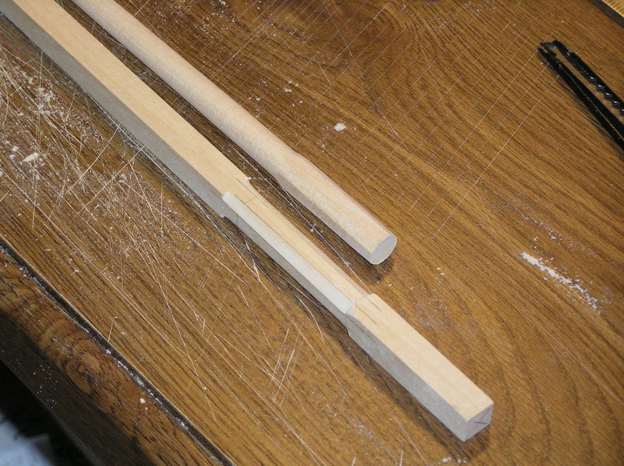
I know this is a little late, but I am a model railroader who is building the Bluejacket Jefferson Davis. (Started before the MSW Crash.) In all of my years, I have never thought "I wish I had a lathe". But spar making made me look into it. I ended up with a Grizzly Industrial hobby lathe/disk sander. Kind of like a home made lathe, but better quality. And It is relatively inexpensive. Mine cost about $55 US, but it is now up to $89 US. Since I am incapable of using a plane of any sort, this was a lifesaver. (Modelsaver?) I start with square stock, put it in the lathe, use a Stanley rasp to cut it down to Octagonal shape. (Actually, I cut it pretty far down with the rasp) then use #80 sandpaper to get it round and tapered. I hand sand it with finer sandpaper to get a nice smooth finish. It is a pretty inexpensive way to get nice round (or whatever) spars.

-
mtaylor reacted to a post in a topic:
Raising the yards
-
So I took a chance and sent an email to PRIDE2 dot org. I got an answer from Captain Jan Miles. His previous two answers were very detailed and long. But here is what he sent me this morning. Happy to be of assistance. Realize this morning that there is another topsail yard halyard mechanical advantage layout. Shorten the initial section of halyard leading from yard in lowered position up through the pulley in topmast. This section is as short as is feasible meaning there is a block placed on that section as close to the aft side of the pulley in the topmast. The line passing through that block crosses the rig from side to side of the ship. On one end of that line is the hauling tackle I described coming up from the bulwark rail. At the other end can be another tackle serving as a jig...as per my description of mainsail, foresail, staysail and jib halyards. For some reason I did not say this is actually the way PRIDE’s square-fore-topsail-yard is rigged. Here fore-topsail is relatively huge for her size. If you are familiar with the Revenue Cutter style schooner SHENANDOAH of Vineyard Haven, Martha’s Vineyard, Massachusetts it might surprise you to learn PRIDE’s square-topsail is larger than SHENANDOAH’s to square-topsails combined. If your model is of a vessel of similar size to PRIDE & SHENANDOAH, it is very likely this cross vessel arrangement was used. But maybe, maybe not also with a jig tackle at the opposite end from the hauling tackle. So I guess the answer is yes, there is a mechanism between the halyard and deck. I'll have to plan a trip to Baltimore or Martha's Vineyard and see for myself. Thank you both for you help.
-
BobG reacted to a post in a topic:
Jefferson Davis by mrw4297 - FINISHED - BlueJacket Shipcrafters
-
mtaylor reacted to a post in a topic:
Raising the yards
-
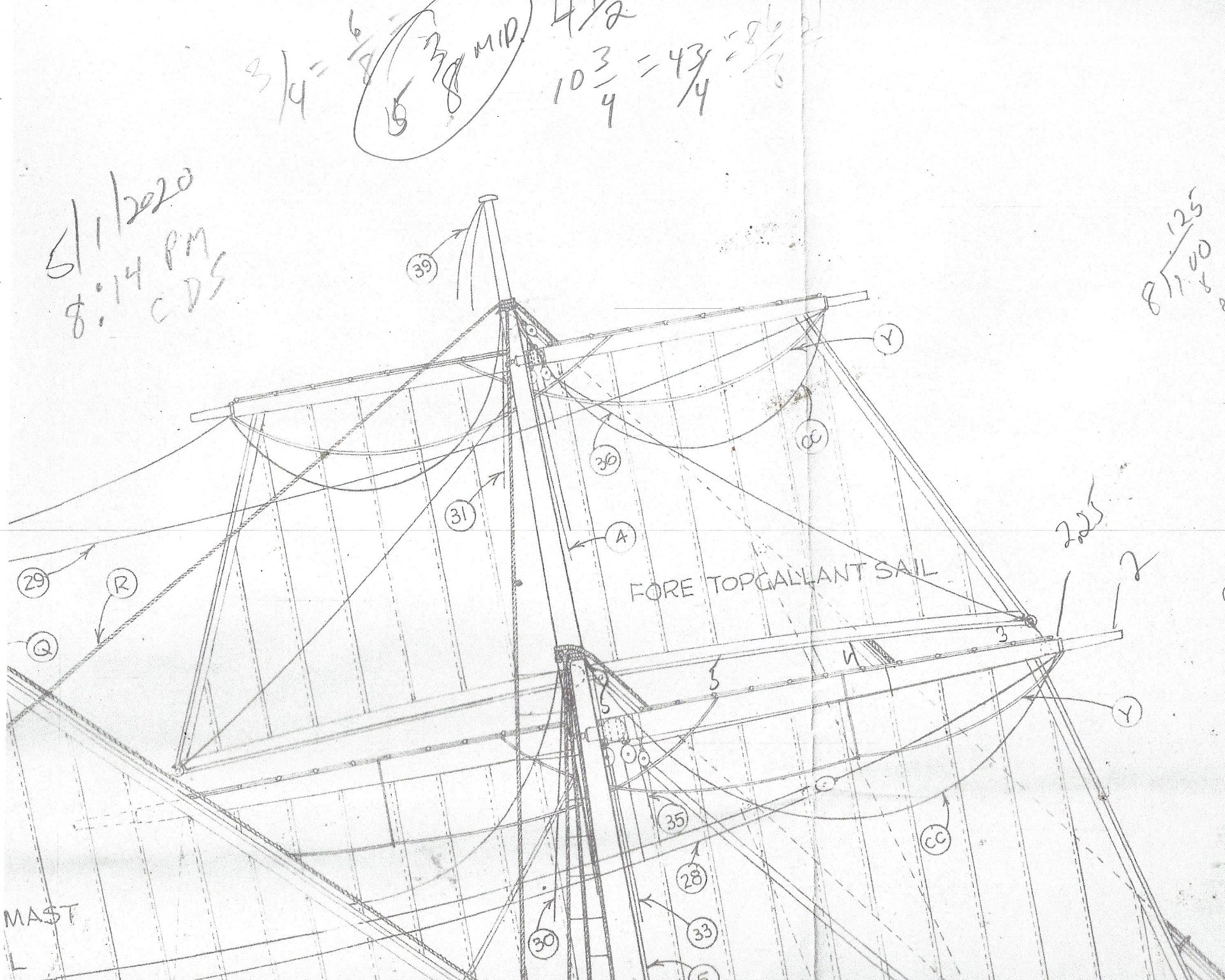
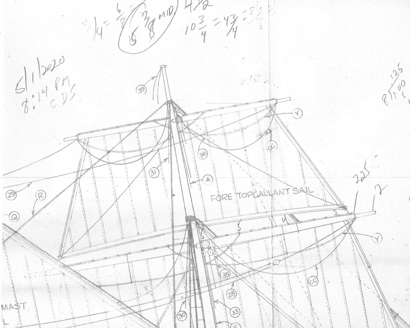
Allanyed, when you look at the original drawing, it is more clear. (Less blurry, not easier to understand) Lines 30 and 31 are both identified as halyards. But as you see in the scan that I attached, they go down from the sheave and are not showing up again on the plan. There is a plan for belaying pins, but 30/31 don't show up there either. My kit is the older version. Bluejacket has updated the kit since then. Maybe the current version shows something at deck level. What I am concerned with right now, is what hardware I need to add to the yard so I can consider it finished. I still have some time before I need to add hardware at deck level. Thanks.
-
Well that was fast. Thank you for your help Nic. And if the mods don't mind: I have kit built and scratch built many models in my lifetime. Mostly railroads. (I was born and raised in Chicago) I have seen good kits, mediocre kits and kits that were a waste of money. Bluejacket kits are among the best I have ever built. Realistic with fittings that are close to scale, and great plans. If only they would run rigging classes a little closer to Chicago...
-
Hello, I had a build log of the Bluejacket Jefferson Davis on the site before the Great Crash. For various reasons, I had to suspend building the model. But I intend to finish it this time. The masts and bowsprit were finished previously. I am now finished with the gaffs, boom and main yard. I am in the process adding hardware to the topsail yard. But for the life of me, I cannot figure out how yards were lifted into position on the mast. I have google my mind out, and gone through this forum. I see a sling holding the main yard, but this yard seems to have nothing. I am assuming that they were lifted with ropes and blocks, but where were those blocks located? Maybe they were not permanent and don;t need to be on the model? And they must have been higher than where the yard is mounted. And I will have the same question for the topgallant yard, as soon as I build it. Thanks for any help you can offer.
-
Hello, I am so glad to see this build log. I had an older version of this model and put up a build log before the crash. This was my very first ship model. It was probably a little too difficult for me, but with the help of the forum members, I built a pretty nice model. I finished the hull and deck furniture, stained everything and cut away the model from the original keel piece. I built the two masts before some family issues arose and I had to stop. I've started up again and have the gaffs, boom and main yard built. I expect to finish it this time. I'll be watching this log and hope you ask for help if you need it. And what I learned is that if I wasn't sure that a piece looked good...I threw it away and built another one. (I am pretty sure I built some pieces 4 times.) Good luck with your build.
- 31 replies
-
- 3
-
-
- Jefferson Davis
- Bluejacket Shipcrafters
- (and 1 more)
-
Thanks John
-
Thanks Frankie, I might not use the padeyes and use eyebolts instead. But I still haven't gotten any information about what the diameter would be. I would hate to "eyeball" it and then find out I was wrong.
-
Thanks John, I just realized I typed the year wrong. The year should have been 1850's. The mast and yards were wooden, not steel. But the picture does answer a question I had about whether the jackstay was in the center of the year or on the leading edge,, as your photo shows it. I have a set of plans from the Joe Lane, which was an earlier version of the Jefferson Davis (different builder), and those plans show a double jackstay. My plans for the JD only show an angle that makes impossible to tell where (or how many) the jackstay is mounted.
-
Hello everyone, I am building the Bluejacket Jefferson Davis. There was a build log before the crash, but I haven;t been able to rebuild it. I have been moving along rather slowly, but the hull is complete and I am working on the masts. I am building the yards and am ready to install jackstays. Bluejacket provides some padeyes for this purpose and I have brass wire that fits the holes perfectly. However, the diameter comes out to about 2.2 scale inches. This seems a bit oversize. I have two other diameters of wire that are 1.65 scale inch and 1.4 scale inch. But, these smaller sizes will be loose in the padeyes. Does anyone know what the diameter of a jackstay would be for an Revenue Cutter build in the 1850's? I am also concerned about the spacing of the padeyes, The plans show them to be spaced about 16 inches apart. However, I was only supplied enough padeyes to space them about 30" apart. Would anyone have an opinion on the spacing? Thanks for all your help.
-
No Ratlines on Revenue Cutter Dallas?
gregs1234 replied to RichardG's topic in Masting, rigging and sails
The Revenue Cutter Joe Lane (late 40s) and Jefferson Davis (early 50s) had ratlines. I think they might have been larger than Dallas. -
Thanks John.
-
So as a follow up to the original question, did to bottom of the topmast rest on the crosstrees or did the fid rest on the crosstrees. If the fid rested on the crosstrees, was the bottom of the topmast just bare and between the crosstrees or did it have some other support?
-
The instructions for my Bluejacket Jefferson Davis indicate that the US Revenue Service would have painted white: deck furniture, ends of all spars, bowsprit, mast doublings, mast below spider bands, bulwarks and bulkheads. I have pictures of other models of JD and they all have the ends, doublings, and the bottom of the masts painted white. (Even one model that is otherwise stained wood). JD was built around 1853.
-
Geez...that was fast. Jay, I can;t put another hole in the jib boom. There already is a hole where the sheave is installed. I never heard of a cut splice before, but Google has a lot of pictures of the splice. So as soon as I practice a little bit, a cut splice it will be. Thank you all for your help. (And I will try to re post my build log, a little bit at a time.)