GAW
-
Posts
183 -
Joined
-
Last visited
About GAW

- Birthday 08/16/1934
Recent Profile Visitors
729 profile views


-
 archjofo reacted to a post in a topic:
Falls of Clyde 1878 by GAW - scale 1: 96 - iron 40 frame hull centre section
archjofo reacted to a post in a topic:
Falls of Clyde 1878 by GAW - scale 1: 96 - iron 40 frame hull centre section
-
 archjofo reacted to a post in a topic:
Falls of Clyde 1878 by GAW - scale 1: 96 - iron 40 frame hull centre section
archjofo reacted to a post in a topic:
Falls of Clyde 1878 by GAW - scale 1: 96 - iron 40 frame hull centre section
-
hexnut reacted to a post in a topic:
Falls of Clyde 1878 by GAW - scale 1: 96 - iron 40 frame hull centre section
-
hexnut reacted to a post in a topic:
Falls of Clyde 1878 by GAW - scale 1: 96 - iron 40 frame hull centre section
-
Jorge Diaz O reacted to a post in a topic:
Falls of Clyde 1878 by GAW - scale 1: 96 - iron 40 frame hull centre section
-
tlevine reacted to a post in a topic:
Falls of Clyde 1878 by GAW - scale 1: 96 - iron 40 frame hull centre section
-
tlevine reacted to a post in a topic:
Falls of Clyde 1878 by GAW - scale 1: 96 - iron 40 frame hull centre section
-
tlevine reacted to a post in a topic:
Falls of Clyde 1878 by GAW - scale 1: 96 - iron 40 frame hull centre section
-
tlevine reacted to a post in a topic:
Falls of Clyde 1878 by GAW - scale 1: 96 - iron 40 frame hull centre section
-
tlevine reacted to a post in a topic:
Falls of Clyde 1878 by GAW - scale 1: 96 - iron 40 frame hull centre section
-
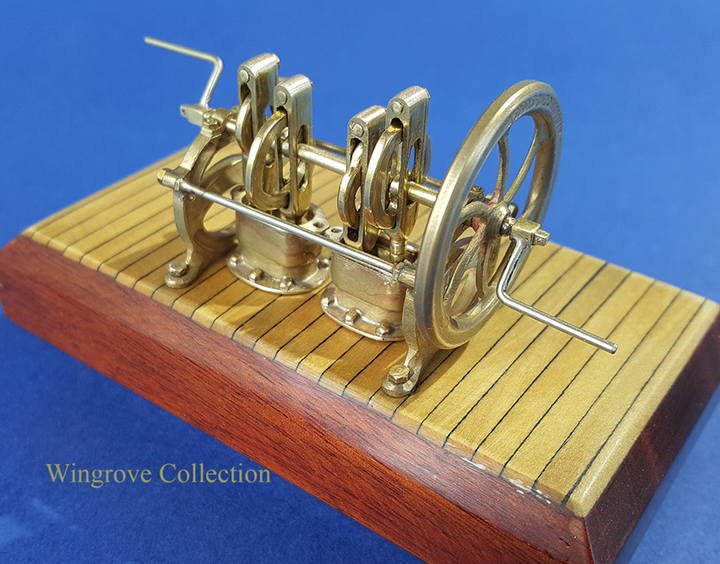
 Fig-171- The working model of the Wallace & Sons Patent Bilge Pump, as originally fitted to the Falls of Clyde in 1878. All that is covered in this Build Log, is at this time, is being assembled for permanent public display on the Barque Glenlee, on the Clyde in Port Glasgow, Scotland. This to show to a younger generation how the famous Scottish iron ships were put together on the Clyde in the late 1800s. < https://thetallship.com > Fig-172.mp4
- 281 replies
-
- 13
-
-
- tanker
- sailingship
- (and 1 more)
-
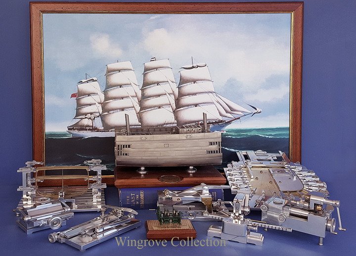
Fig-170- the complete project, together with the tool set, required to create it - and a most rewarding one.
- 281 replies
-
- 14
-
-
- tanker
- sailingship
- (and 1 more)
-
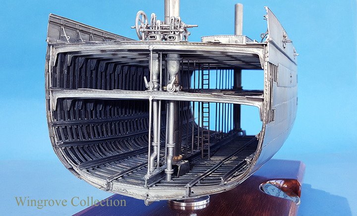
Fig-168- The Bilge of the Falls of Clyde model, showing the suction end of the down pipes, now completed.

- 281 replies
-
- 11
-
-
- tanker
- sailingship
- (and 1 more)
-
Fig-167- The working end of the Bilge pumps at 96th scale.

- 281 replies
-
- 9
-
-
- tanker
- sailingship
- (and 1 more)
-
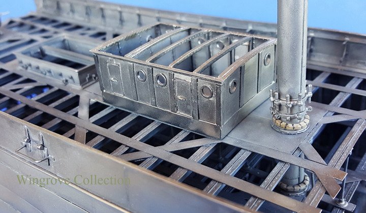
Fig-166- End view of the finished Centre section model showing the complete Bilge Pump assembly detailing
- 281 replies
-
- 12
-
-
- tanker
- sailingship
- (and 1 more)
-
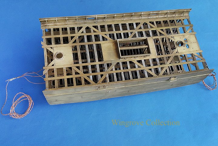
Fig-165- The stub masts, Bilge Pumps and deck house were removed and plated separately, then reassembled after the plating process was completed.

- 281 replies
-
- 9
-
-
- tanker
- sailingship
- (and 1 more)
-
Fig-164 - Now to return to the main model of the centre 40 frames of the Falls of Clyde - The finish - an iron ship, I did not wish to show it in brass, or with a rusty finish, so chose a dull nickel finish, the problem was would the electrolytic Nickel throw into the centre of the model from both ends? Chrome will throw in a direct line only and anything in it’s way will form a shadow. However Nickel can to a limited extent throw around corners, so it was worth a try. There is a none electrolytic Nickel plating available, and plating kits for the asking, but I had just the one large item to plate , and a very good and understanding plater on hand, so thought to trust him with the job in hand as a starter. Good decision - 95% of the model took the dull Nickel plate, with just a very small amount with a questionable finish right in the centre. I touched these areas up with a small plating kit for dull Nickel and the job was completed.
- 281 replies
-
- 9
-
-
- tanker
- sailingship
- (and 1 more)
-
Fig-163- All fitted and ready to go. - view of the font of the Wallace & Sons Bulge Pump as originally fitted the the Falls of Clyde.
- 281 replies
-
- 11
-
-
- tanker
- sailingship
- (and 1 more)
-
Fig-162- All fitted and ready to go. - view of the font of the Wallace & Sons Bulge Pump as originally fitted the the Falls of Clyde.
- 281 replies
-
- 11
-
-
- tanker
- sailingship
- (and 1 more)
-
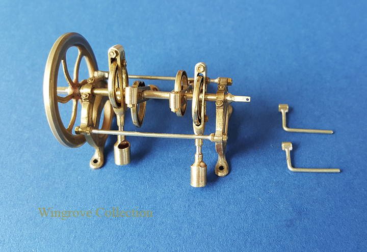
Fig-161- Here can be seen the complete drive shaft and piston assembly.
- 281 replies
-
- 9
-
-
- tanker
- sailingship
- (and 1 more)
-
Fig-160 - The assembly was very informative, as it was most probably the main reason the Patent, was dropped very shortly after it was put into practice and manufactured. One of those ideas that look very good on paper, but turn out to be less so, when put into practice. Not so much for the design, but for the maintenance, to keep it running, and that on a ship at sea. The drive shaft has assembled on it the four complete cam units, each keyed to the shaft, with a distance piece between to locate them directly over their respective cylinders , into which they are then dropped as a unit, then mounted between the two end plates. With the assembly then completed with the fly wheel and handles to work the pumps at each end. It soon became apparent that should one of the pumps be in need of attention - replacement valve - then the assembly of the drive shaft complete with all four cam units would need to be removed from the frame to get to any one of them. It would be impossible to remove one piston/valve cup, with out removing all four With a crank shaft and connecting rod to the piston/cup containing the offending valve - on the more normal Bilge Pump design - just two bolts at the crank shaft end, is all that would be needed to be removed to extract that offending piston/cup valve part. In the working miniature, after the problem of making the cams, the drive shaft proved to be the next most problematic. It being exceedingly thin, yet needing four slots in it for each of the keys for the four cams. I solved the problem by using stainless steel hypodermic needle tubing, one for the shaft, and a second, the next size up to slip over it, for the distance pieces between the cams. The shaft was threaded at each end to take the end locating piece, that also included the bearings and squared ends for the handles.
- 281 replies
-
- 10
-
-
- tanker
- sailingship
- (and 1 more)
-
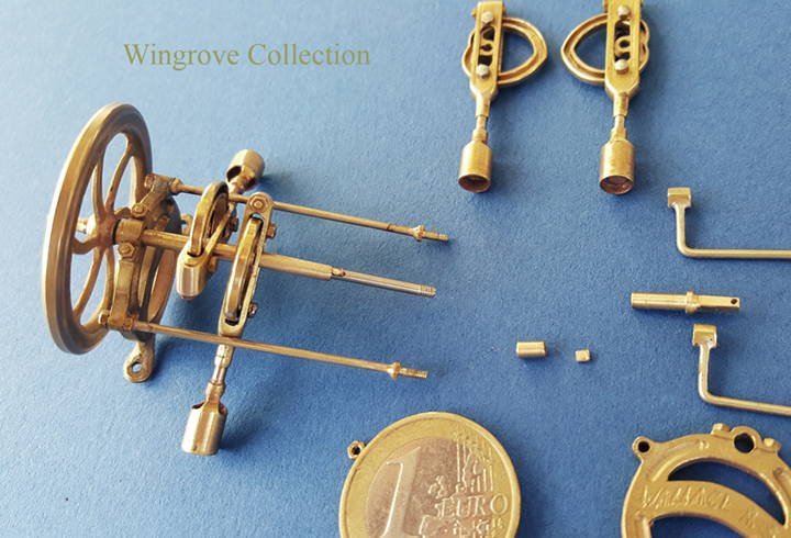
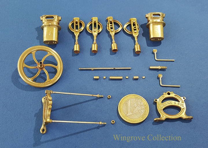
Fig-159 - A full set of parts for the working model - the two twin pump casings at the top, together with the four cam assemblies, with cages, pump shafts and pistons/cups. Below them is the flywheel and drive shaft, distance pieces and handles for working the pump. And at the bottom the Bilge Pump frame, consisting of two end plates and connecting rods.
- 281 replies
-
- 8
-
-
- tanker
- sailingship
- (and 1 more)
-
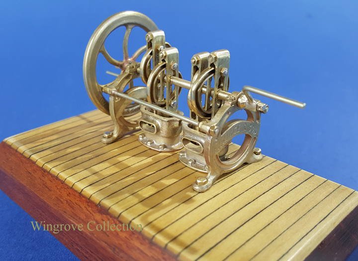
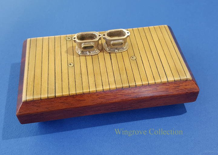
Fig-158 - The base for the working model, with the two twin pump cases installed .
- 281 replies
-
- 9
-
-
- tanker
- sailingship
- (and 1 more)
-
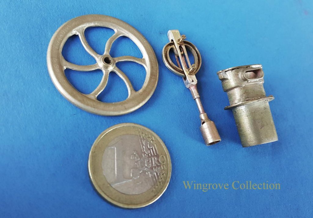
Fig-157 - Now we come to the second working model of the pump mechanism, shown here is the fly wheel, the one of the Bilge Pump double cylinders, together with one of the four cam assemblies. This consists of the cam set in the rectangular cage, to the bottom of which is the pump piston/cup. What would have been two rollers, set to run in the cam groove, I have substituted two fine brass screw, with lock nuts to hold them in place. When the cam rotates, it is these rollers/screws that then create the vertical movement of the pump. Each of the cams are individually keyed to the drive shaft.
- 281 replies
-
- 9
-
-
- tanker
- sailingship
- (and 1 more)