Jaager
-
Posts
3,051 -
Joined
-
Last visited
5 Followers


About Jaager

- Birthday 09/11/1946
Recent Profile Visitors
5,935 profile views


-
 woodartist reacted to a post in a topic:
Does cherry carve well?
woodartist reacted to a post in a topic:
Does cherry carve well?
-
Scottish Guy reacted to a post in a topic:
Roar Ege by Scottish Guy - Billing Boats - 1:25
-
Keith Black reacted to a post in a topic:
Roar Ege by Scottish Guy - Billing Boats - 1:25
-
 Well, the original Italian kit mfg who developed the POB method - named them "bulkheads". The very name of the method uses it POB Plank on bulkhead. Bulkhead is a complete part of how it is described. But it is not an actual bulkhead Steel ships have bulkheads. Wooden Chinese seagoing junks had bulkheads. If Titanic had been built with actual bullheads - instead of the transverse barriers stopping short of being chambers that could be sealed, it may have floated long enough and level enough for a more organized abandonment or even help from something large. As for yachts, is it that they are molded more than a frame? Thinner than a frame? Are there yachts built like a submarine with dogged hatches in a barrier across the hull that allows it to be a series of isolated cells? An actual bulkhead is an integral part of the internal structure of a vessel. In POB, it is just the shape inside the hull at the station where it is - thus a mold (mould). The midline support is not a keel. It is a central spine. These pretentious names "bulkhead" and "keel" help with advertising and salesman hooks. They are too inculcated to be changed for most kit builders. But, just like calling a yard - a "yardarm" - calling the part a bulkhead or keel outside its kit realm is a reflection of depth of knowledge.
- 56 replies
-
- 2
-
-
- Roar Ege
- Billing Boats
- (and 2 more)
-
Keith Black reacted to a post in a topic:
Roar Ege by Scottish Guy - Billing Boats - 1:25
-
 Scottish Guy reacted to a post in a topic:
Roar Ege by Scottish Guy - Billing Boats - 1:25
Scottish Guy reacted to a post in a topic:
Roar Ege by Scottish Guy - Billing Boats - 1:25
-
My apologies if I am missing the questions or covering something already addressed. Naming these particular components "bulkheads" often leads to misunderstanding. They are molds. They stay in the model for most models of decked ships. They are not seen, so it does not matter. This model is a clinker built open boat. The molds are temporary forms - or at least they should be. I would build it the same way as I would any model of an open boat. I did not see any plans' preview on the Billing site, so I have no knowledge of what is with this one. A central spine - the top of which stops where the actual keel meets the garboard plank. A series of molds to give support and temporary shape to the planking. When it has done its job, it is discarded - I mean the spine and the attached molds. The actual keel sits on the spine. The P&S garboards bond to it. The subsequent rows of planking added - row two P&S - row three P&S, etc. Doing just one side to completion and then the other is very bad practice. Continuously check for bilateral symmetry. Adjust as necessary. I have seen Viking hulls with totally misunderstood planking runs. One such was a cover story on the last series of Ships in Scale. The problem was that the extreme upturn of the planking at the bow and stern are an illusion. No real planks can turn up like that. There was a gentile sheer. The up turn was a carving. It started at the rail and lower- an elaborate stem - not just a rabbet. The spine and molds can be any material that will hold up. They are disposable. Actually for the scratch, they can be a carved sold Pine mold, carved horizontal layers, carved transverse layers - which ever fits your style. The ribs for the model go in after the planked shell is completed. Unlike carvel, they cannot be bent or heat bent*. The "Z" of the planking requires pattern work to get a fit. Anything ferrous on a model is a disaster. It rusts , stains, and dissolves away. On a static model, you will not live long enough to see it - unless someone invents a Niven Autodoc real soon. Soft brass wire, or given its rapid rate of tarnish - soft copper wire - a possibly interesting color better than bright brass on a Dark Ages beasty. Having nothing instead of roves works too. I would consider the tricky structures on the inside of the keel to be a keelson- attached along the keel - not of the keel. *(Heat allows the lignin to be manipulated. Water does not dissolve it. If it did, trees would melt. Steam is just a messy way to apply heat at model scale. It swells the surface fibers. For full size timbers - it is necessary.)
- 56 replies
-
- 2
-
-
-
- Roar Ege
- Billing Boats
- (and 2 more)
-
allanyed reacted to a post in a topic:
Need help with HMS Beagle bowsprit
-
Jaager reacted to a post in a topic:
replacing plastic mast and spars
-
Ryland Craze reacted to a post in a topic:
Communicate with Moderator
-
Communicate with Moderator
Jaager replied to carlfmiller's topic in How to use the MSW forum - **NO MODELING CONTENT**
I find that an easy way is to scroll down to "Who's on line" set the cursor on a red or pink? name. A window should open. Click on message, filling the blanks and type the message. -
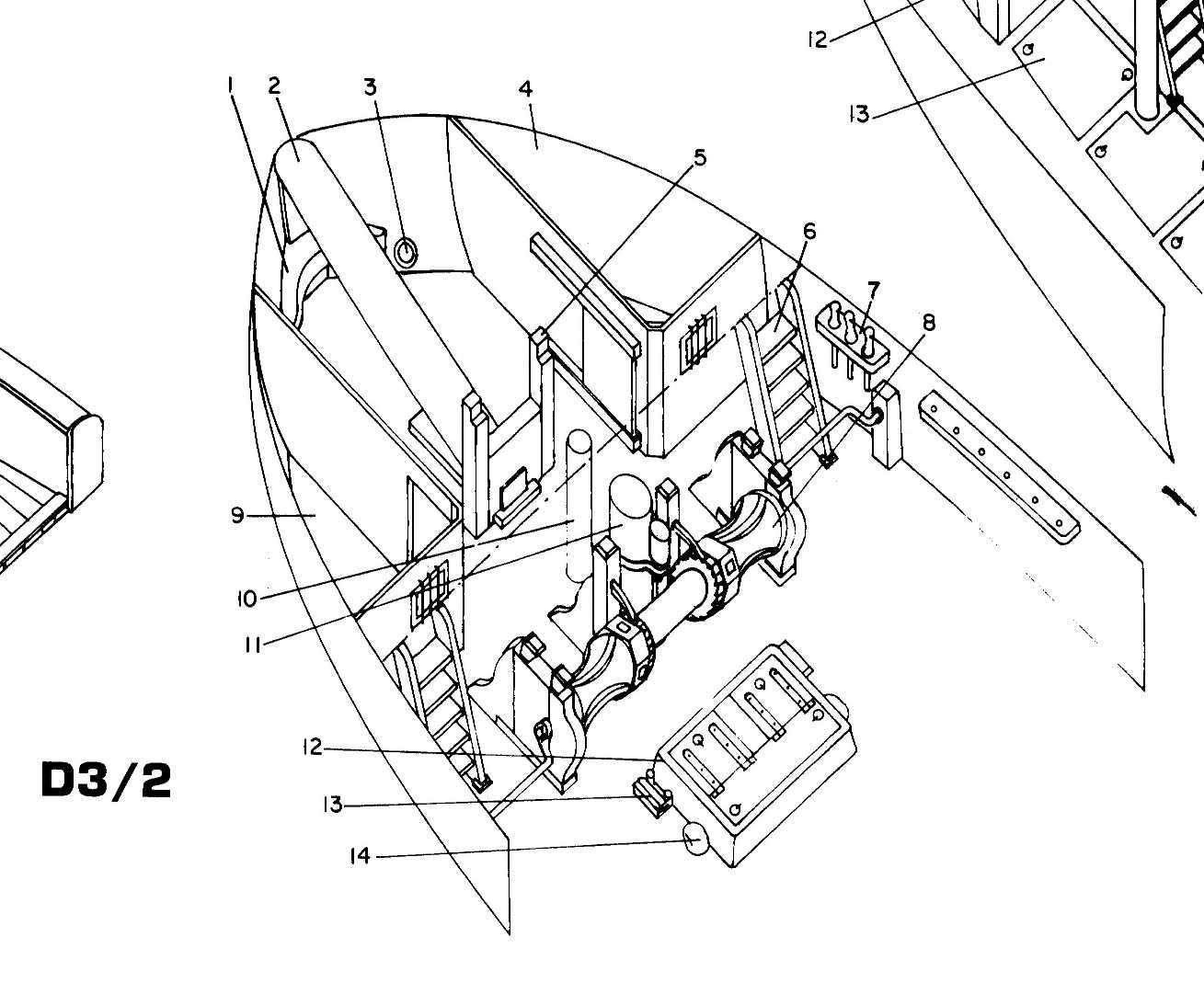
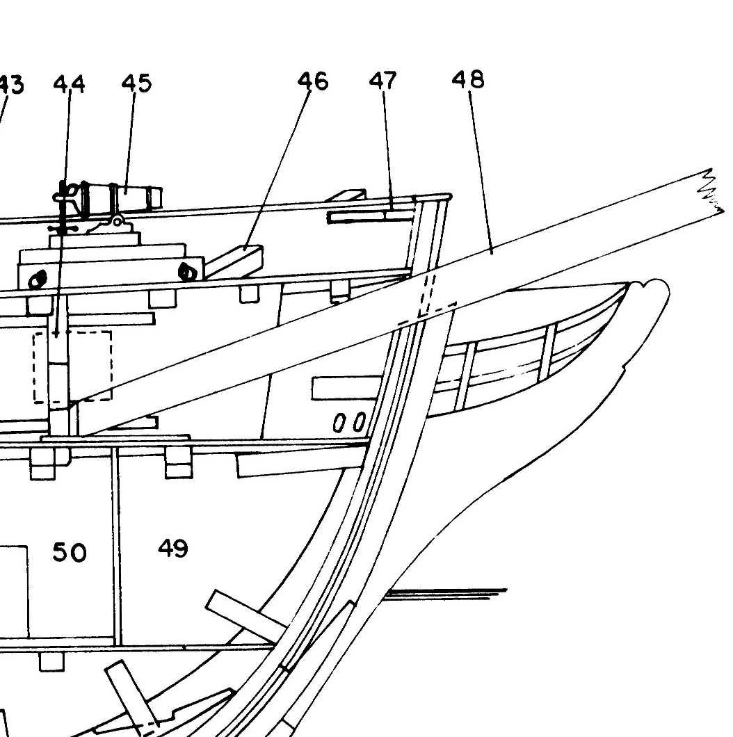
With a plan of the bowsprit, it is just a matter of figuring out how to match. Wooden kit plans are obligated to show WHAT should be done. If they do not, that kit is flawed. Explicit instructions for every step are the need for a beginner kit. The more sophisticated kits do not need them so much. The procedures and skills are variations of what has already been learned. At least this is my take on the situation. The OcCre site lists HMS Beagle as being "medium difficulty". A significant degree of prior experience is expected. The instructions should not be expected to include what should a part of a builder's skill set going in. If jumping ahead rather than paying the dues has not worked out, storing the advanced kit and going to a beginner kit series should fix the situation. For Beagle's bowsprit - Here is the interpretation of the structure done by Karl Heinz Marquardt :

-
Underhill's books appear to be still available from the original publisher's web site in the UK Brown, Son and Ferguson His plans are also there - almost all are later 19th and early 20th century subjects https://www.skipper.co.uk/catalogue/books/page https://www.skipper.co.uk/catalogue/item/masting-and-rigging L 22 https://www.skipper.co.uk/catalogue/item/plank-on-frame-models-and-scale-masting-rigging-volume-1 L 25 https://www.skipper.co.uk/catalogue/item/plank-on-frame-models-and-scale-masting-rigging-volume-2 L 20 https://www.skipper.co.uk/catalogue/item/deep-water-sail L 30 https://www.skipper.co.uk/catalogue/item/sailing-ship-rigs-and-rigging L 16 Both ANCRE books are " available" as written, the shipping is so high that I will no longer consider any purchase. They need a US agent, and not one focused on avarice - cough NIP cough https://ancre.fr/en/14-basic-books AN INTRODUCTION TO PLANKED ON FRAME SCALE MODEL SHIP BUILDING AN INTRODUCTION TO PLANKED ON FRAME SCALE MODEL SHIP BUILDING “DOCKYARD STYLE” An introduction to Planked on frame model ship building through more than 200 pages illustrated by approximately 500 colour photographs and captions. This guide includes explanations on all the techniques used during the construction of a model. EAN : 9791096873920 Model MODELA En stock Print Author : Adrian SOROLLA translation by GILLES KORENT 49 Euro The Art of Shipmodeling - Bernard Frolich The Art of Shipmodeling describes the author's experience and methods in 300 pages abundantly illustrated with numerous drawings, sketchs and more than 600 commentated photos. Model LART En stock Print Author : Bernard Frölich 89 Euro
-
Just starting out, you cannot know which shapes will be useful and which are of little or no use. And that determination is individual - different for each of us. It looks to me that you have done what is economical and practical. Time, and use will show you which shapes are your favorite. If or when these wear out or dull, you can visit jewelers supply houses and buy quality individual files. When you get to wood for the whole project, masting will be a minor portion of the whole. Different needs and challenges at every stage. When comes the time, try to avoid seducing yourself into something too ambitious. For a PhD, the old stats were 50% of those who start get to the dissertation only level and only 15% complete to the degree. It is not that the course work is all that difficult, it is not. The faculty is on your side. They help and encourage. It is that the process is an endurance test. I am not unsure that wooden ship model building - especially scratch is not an even more challenging endurance test.
-
Drill bit suggestions
Jaager replied to SiriusVoyager's topic in Modeling tools and Workshop Equipment
I like CML https://www.cmlsupply.com/bright-finish/ I aim for USA made if it is a choice for bits no economy to be had here. What are you using to drive the bits? -
I don't think that you really want any of the three of them. It is difficult for any single book to cover more than a specific era for model construction methods. Anything broad tends to be superficial. The two volumes of the Ship Modeler's Shop notes are gems taken from the NRJ. The basic skills are covered in logs or technical forums here - sometimes a chore to find - but also to see variations on the theme. There ain't no single "answer to it". To stay out of a fugue state - it helps to specialize. Once you specialize, your books should be reprints of contemporary books or books that show the actual practice. Find out what was actually done and try as best you can to duplicate it at model scale. Gaasbeek comes from a very special time. WWI era. There is also Estep and Desmond and then Charles Davis' misleading application of what was done for WWI as being relevant to any time before then. For 20th century large wooden vessels - they are OK sources. Except for a failed and panic based effort to overcome the U boat sinking of bulk carriers by using wooden hulls, most large wooden vessels from then on were fantasy based replicas famous historical vessels. These methods are much more reflective of iron and steel engineered hulls than the construction methods from the Age of Sail.
-
HHS - High Speed Steel oops - HSS I think that the major categories are steel and carbide. Not for files but for cutters. For drill bits - with what we do and the small diameters we use - there is wiggle and flex - carbide is not flexible it may stay sharp a lot longer than steel but any lateral stress breaks it. For files it is diamond vs steel the steel files do have some bend to them, but they object to being bent over the work like a Japanese garden bridge. Down force at both ends and work resistance in the middle and heat from friction and a good quality file becomes two pieces. It cost me either a Vallorbe Glardon or Contenti or Grobet or Vigor file to learn that lesson. Diamond must be easier and less expensive to produce than working grooves into hard steel. The needle file On Sale deals are mostly diamond coated. I bet that the metal that supports the diamonds ain't the best.
-
Unless the color is not appropriate, using it 'As Is' will work; no treatment is necessary. If darker is the goal, a wood dye will do the job. Blue Mold is not like the fungus that turned a trunk of Apple that I had not prepared correctly into meal. Oxalic acid does work. I used it on a door of an old book case, Took it back to looking like fresh cut wood. It was an antique - extreme refinishing was a bad idea - destroyed any value, but the stuff worked. As far as I can tell, Blue Mold is benign except for the color thing. If only we could save all of the infected Holly and off-white Holly from going to the breakers and buy it.
-
You have to try them and see if they work. The tool texts that I have read have it that diamond is for metal - primarily steel is my guess. I use 220 grit sandpaper more for a smooth finish than removal. HHS jeweler's files - the 4" have the cutting surface designed to cut wood. needle files - for just this I would use the flat rectangular equaling shape - quality is expensive - using economy POS is more expensive in time wasted, unneeded frustration, and lack of joy in how they perform. It is a more difficult grip , but the finger exerting the downward pressure should stay directly above the wood. HHS that is hard enough to hold an edge is brittle - is does not bend - it snaps. They come in different "cuts" 00 most aggressive to 6 smoothest 0 2 4 seems to be range readily available. I have never gotten a rasp to work for me at the scales I am about. They rip and tear. Usually deeper than I wish. This is why I was so surprised at how well the Stewmac razor file worked. As far as I know, it is unique. No other source. It is expensive. If you have an open ended budget and you are in this at a serious level and for the long haul - it is worth having. Until you get to a point where you do not have to ask - a normal razor saw - maybe even Exacto or Zona will do what you wish. I prefer pull to push but I spent a lot of time with push to get there. It is a tool that is a series of brass tubes. They have a sharp edge at one end -something that brass does not hold for long - and a T handle at the other. They are used to twist a hole thru the center of a cork glass stopper to allow a glass tube to be pushed thru it. When the borer is removed, there is a cork rod in the bore to be pushed out. It looks like a dowel - but just looks like one. These 19th century tech borers do not work so well on Neoprene ( rubber ). That stuff wants to tear rather than cut if the cutting edge is not really sharp. Unless you are in a chemistry or more often a biology lab, I do not see what you would use them for. I have never seen an actual dowel making sawmill - I imagine that a long thin wall steel tube with really sharp teeth - probably a bundle of them - rotating - plunged into the end grain of a bole of wood. If the trunk of the tree is not a precisely engineered series of of concentric rings, a dowel bored from it will have variable grain. Splitting - and using a species of wood that grows straight up - and is dense - and has really really small pores - tends to work better as a small scale simulation of a tall Pine tree's wood. There are demonstrations here doing the same job using larger bore syringe needles to mass produce hardwood trunnels. ( Personal bias - if I use a trunnel, it will be to actually hold two pieces of wood together - and actual wooden nail - or Bamboo in my case. I do not see the point of having shallow - just for show trunnels. These are mostly used on decks. On an actual ship, special effort was made to make the actual trunnels and bolts ( which were covered with a wooden plug ) as invisible as possible. Making a deck that looks like it has the Measles is a not realistic modeler convention.
-
A 90 degree channel 45 degrees L 45 degrees R - probably will need several with a range of depths Way back when, it seemed to me that every "how to build ship models" book covered this method. A miniature block plane, scrapers - small steel luthiers , a freshly broken piece of glass, a single edge razor blade or carpet knife blade in a homemade wooden holder. StewMac has a small flat razor file that eats wood yet leaves a smooth surface (if you get serious about this - they also have one named Ultimate mini scraper - a bit dear in cost, sold out right now, and something you don't want to drop if your working surface is a tempered glass plate with beveled edges - it has some heft/mass. warding files Save the sandpaper until the end. Try Hard Maple for your masts - Birch dowels are made using something like a cork borer - straight grain along the whole length is just luck.
-
There are additional factors to doing this in a way that helps with the result being as optimal as possible. Use an appropriate species of wood - tight straight grain - no pores. Dense is probably good. Split the square starting stock from its plank. A split will be along the grain so the wood will be at equilibrium with its natural orientation from the start. Using a saw will probably be a cut across the grain - usually at a sharp angle - when free from other fibers the angled fibers may seek to be straight. Look up froe for the traditional tool for splitting along the grain and Bamboo froe for a smaller version without the right angle handle.
-
When the dimensions are large enough that wood will work, it is probably imperative to replace plastic spars (masts, yards, booms) with wooden ones - unless you like the top hamper looking like a Willow tree. For plastic spars in kits in 1:96 or small scale, I see some of the yards as being too small for wood to work well - even though plastic is significantly less appropriate. The real recommendation from the professional end of this is to use brass when wood is too weak. Maybe, the half hard brass welding rods? I have never seen any brass for sale that is harder than half hard. Working it down from square stock is probably superior to using a lathe for any spar, but for the really small diameter stock, a lathe's lateral force will probably break a higher portion than it has success with. The rings across the grain that a lathe cutter makes are probably near impossible to totally erase. I thought this is the explicit source: SHIP MODEL CLASSIFICATION GUIDELINES 1980 - DEPT. OF SALES AND SERVICE - MYSTIC SEAPORT MUSEUM it is mentioned - but maybe it is from the USN museums standards. The idea of using brass does not exactly fill me with joy, but there is probably no practical alternative.
-
Allan, Yes, that is essentially what I have done. Except that mine is still the shape of the stations. For my present path, I will have to see if the planks' edge glue bond between each is as strong as it needs to be. Saran Wrap over the plug. My variations: the plug is taller - with a stilt above the rail. Each section between stations is a free agent. In the silted part there are four dowel holes that are at identical locations in each section. The dowels that are Bamboo skewers extend thru each section and hold them together. After the hull planks are bonded, if the shell does not pop off, I can pull the dowels and remove each section separately. I figure that a stuck area should be local. I see that you used Pine. I probably would too, but I bought some off cuts of Yellow Poplar from Yukon for my plugs. It is probably as easy to shape as Pine. It really is a joy to work. It is a shame that color is so squirrely. Otherwise, it would be an east coast answer to AYC.