Search the Community
Showing results for tags 'brigantine'.
Found 11 results
-
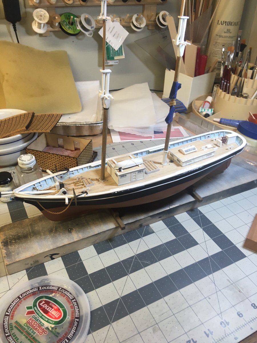
 BlueJacket was commissioned to build the MS model Newsboy by a client. We found an old kit over in Sweden and got it. Model Shipways actually did 2 kits of it, the other was a larger 3/16"=1' scale. The larger one had a foremast top, while this model does not. Our client was impressed by Pete Jacquinth's larger model. As is becoming normal here, Al builds the model but hands it off to me for the rigging. Here's what I received: (yards boom gaff not shown)
- 117 replies
-
- 10
-

-
- Newsboy
- Model Shipways
- (and 2 more)
-
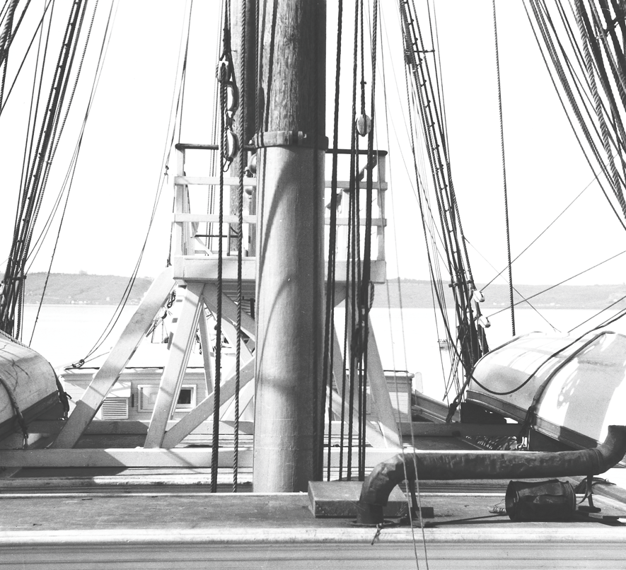
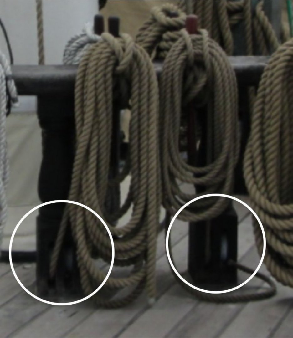
 This is a research question on the structure and arrangement of fife rails constructed in smaller American merchant ships of the late 19th century. This question specifically pertains to the 1891 American West Coast brigantine packet ship Galilee, which is the subject of my topic found here in the Model Ship World forum. I specifically wish to understand the basic structure of a "partial" fife rail. Galilee’s original forecastle was constructed just aft of the foremast and so close to it that the sides of the mast’s fife rail evidently were attached to the forward bulkhead and were spanned by a transverse rail forward of the mast. Two corner posts evidently supported the forward section of the rail. No details as to the number of belaying pins or other features of this structure were provided. The following image was taken from the plans of Galilee produced by G.C. Berger of the former Pacific Marine Research Society* in San Francisco sometime during the mid-1930s or later. The foremast fife rail in the brigantine Galilee from the plans of the ship produced by G.C. Berger some time after the mid-1930s. I obtained this plan through the National Park Service in San Francisco One feature often seen in online photos and illustrations of fife rails is the presence of sheaves in the corner pedestals. Were these sheaves associated with specific types of running rigging that would be applicable to the square-rigged foremast in a brigantine? Would they have even been required for a relatively small packet ship? Cropped photo of the mainmast fiferail sheaves in USS Constellation, Baltimore Harbor, April, 2012. (Photo by Joel Abroad via flickr. Some rights reserved.) The following is the best photo I have of Galilee showing the various halyards, etc., that were evidently secured at the unseen fife rail. Since I am not really conversant about the kinds of running rigging such a ship would have, I can’t tell what each of these lines would go to. Would any of these have required sheaves in fiferail pedestals? Lower foremast of the brigantine Galilee showing the few lines of running rigging leading to the fife rail at its base. Most of the upper running rigging lines ran down to the main pin rails through thimbles(?) attached to the shrouds. (Courtesy of the Carnegie Science Library, c. 1906) Any assistance finding illustrative examples of such a fife rail would be appreciated. I have already done due diligence in trying to find examples on the Web and within the MSW site using keyword and image searches, but there is very little information on this topic and virtually nothing showing the kind of fife rail I am looking for. Thanks. Terry *The "Pacific Marine Research Society" was formerly called the "Pacific Model Society," whose founding was "to encourage the preservation of Pacific Coast maritime lore." ( From the Senate committee record Maritime museum; Stones River National Battlefield; Western Historic Trails Center; and Pinelands National Reserve Visitors Center: hearing before the Subcommittee on Public Lands, National Parks, and Forests of the Committee on Energy and Natural Resources, United States Senate, One Hundredth Congress...Vol 4; GPO, 1988.) This is the only reference I could find to the organization itself on the Internet. Some records from the Society remain.—RTE
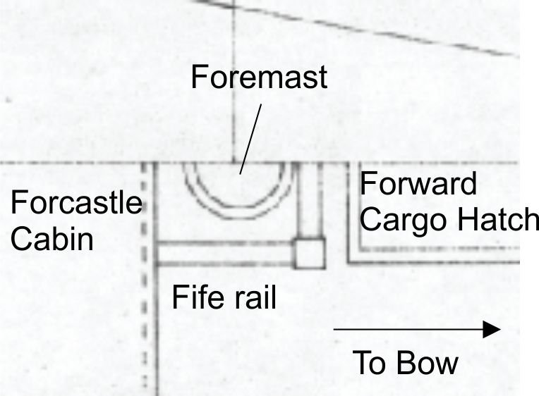
-
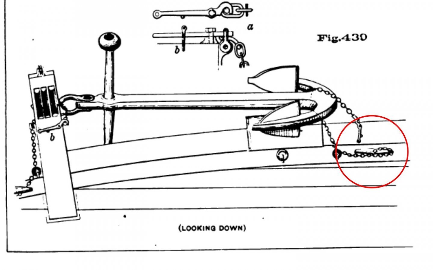
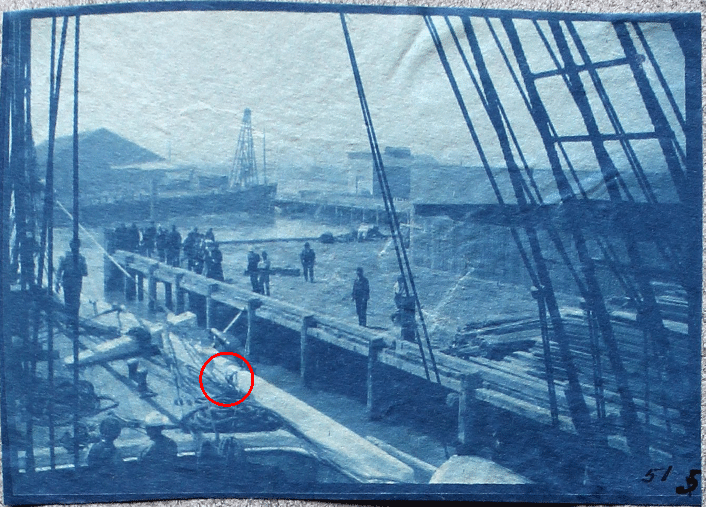
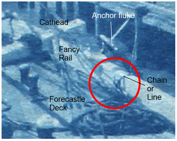
This topic pertains to the proper securing of bower anchors in latter 19th-century merchant ships. I have several poor-quality photos of the foredeck of a brigantine merchant ship (the Galilee) taken sometime during 1905–1908, showing how her anchors were secured when underway. This is probably the best of the lot. Photo showing the brigantine Galilee being fitted out as a geomagnetic research vessel in 1905, probably somewhere in the vicinity of San Francisco Bay, California. The circled area is where the chains/lines securing the lower end of the anchor were tied off. (This and following photos Courtesy of the Carnegie Science Library.) Closeup of the area circled in the above photo. I am in the process of adding the remaining deck furniture and fittings to my digital model of Galilee. My questions pertain to the size, shape, and orientation of the cleats evidently used to secure the lower end of the anchors. What would be the size of the cleat? I've seen the rule of 1 inch of cleat length per 1/16 inch of line diameter. However, in many diagrams showing stowed anchors, it is small chain that was used for this purpose. So, what is the rule if chain is used? Galilee's anchors would have been a minimum of 600 lb. each, about half of which would have been borne by the anchor cleat. Would this have been a factor in selecting the cleat size? Determining the likely shape of the cleat is important for a historically-accurate model. I have found a source of so-called "antique" cleats here. The shapes are quite varied as one can see. Would the type most likely be just a basic cleat such as this one? I have read about—and also experienced—the proper orientation of lines taken to mooring cleats. Typically, the line secured to a cleat should run horizontally perpendicular (or tangentially) to the cleat. Cleats are weakest when the tension pulls upward. So would a cleat securing an anchor likely be bolted to side of a rail or to the deck adjacent to the rail? The latter configuration would result in a more upward tension. However, Figure 430 in Plate 94 of the USNA's Text-book of Seamanship (Luce, 1884) suggests this could have been the case. Diagram of the method for securing a bower anchor in a mid-19th-century warship from the cited USNA reference. The circled cleat appears to be fastened to the deck or a waterway. (The image is found in Plate 94 located between pages 246 and 247.) Any comment or directions to other sources to resolve these questions would be very much appreciated. Terry
- 5 replies
-
- 2
-
-
- anchor cleat
- brigantine
- (and 3 more)
-
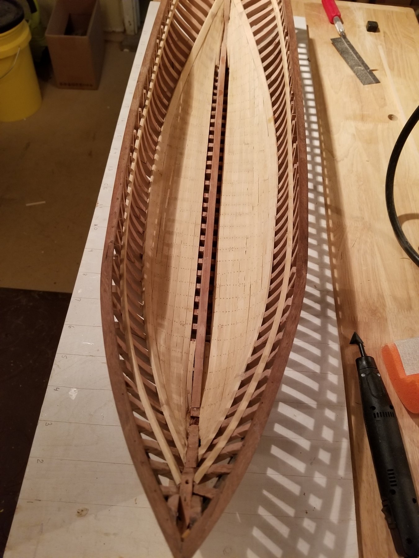
 With this post, I'm beginning a build log for Leon. 302 tons, built in 1880 in Norway, traded until 1915. Model is 1:48, about 2 1/2 ft on deck. Structure is all Swiss Pear, planking - internal and external is Pau Marfin, rail and wale is Indian Rosewood. Much planking and decking will be left off so that the internals will be visible. I just ordered 6 little oil latterns with LEDs that will eventually light up the interior of the hold. Most helpful resources so far are Underhill's Plank-On-Frame Models, Crother's American-Built Packets and Freighters of the 1850s, Tosti's Young America and various forums on this website. Heading to San Francisco shortly to review Ron Cleveland's research material for his model of Leon in the 1970s. Suggestions from anyone who has ideas about how to research the internal construction are more than just welcome, they will be warmly appreciated! For now the bilge ceiling (meaning the common planks between the keelson and the bilge stringer). Next, I'll be planking the exterior to match the interior. I'm planking inside and out, in sections so that I can best judge what to leave out for maximum visibility. I haven't decided yet if I'll be cutting out some of the frames. Until next time.
- 108 replies
-
- 28
-
-
- Finished
- brigantine
- (and 2 more)
-
 Hello Just started building the Brigantine Schooner "Gigino", an Italian sailing Vessel from the Early 20th century. Actually I'm very fond of Schooners and Ocean Paddle Steamers as well, and I plan to work on "Barquentine cote d'émeraude" in the near future, ((supposing that I find the Plan (I hope so)). I'll follow the same technique, which is Double planking on Bulkheads. The first layer of planks will be 3 mm Balsa wood to get a tough body, while the second is 1.5 mm is to get a natural wood finish look. I guess it won't be easy to find a 1.5 mm Balsa wood with clear wood grain appearance and it would need some research to use coloring to get that look. Thank you Models in Progress L'Etoile Vapor Rimac 1848 - a side Wheel Paddle Steamer Previous Models Bluenose II
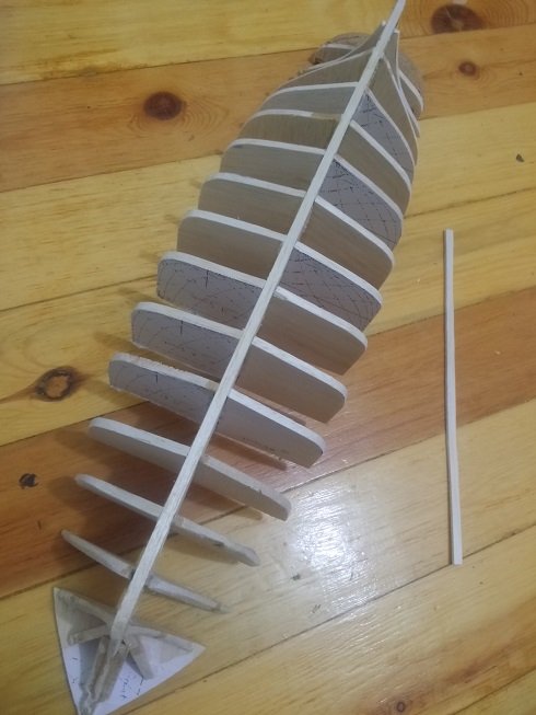
- 26 replies
-
- 10
-
-
- finished
- brigantine
- (and 2 more)
-
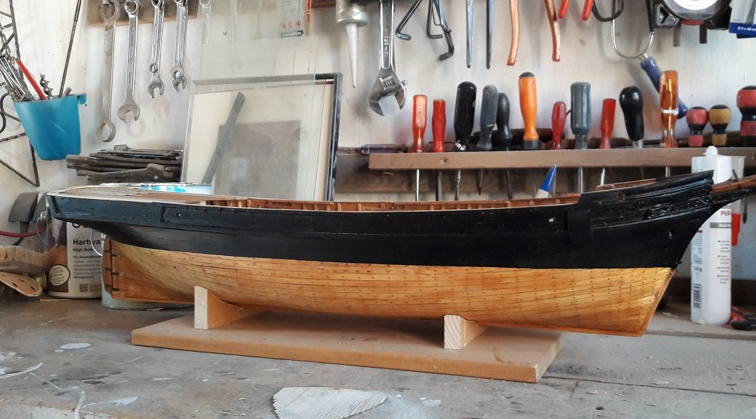
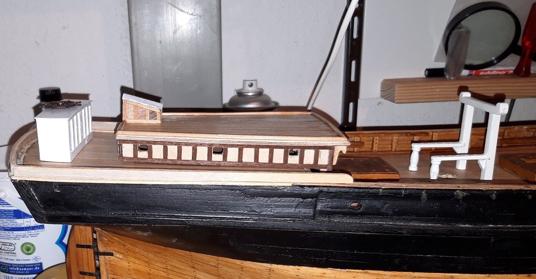
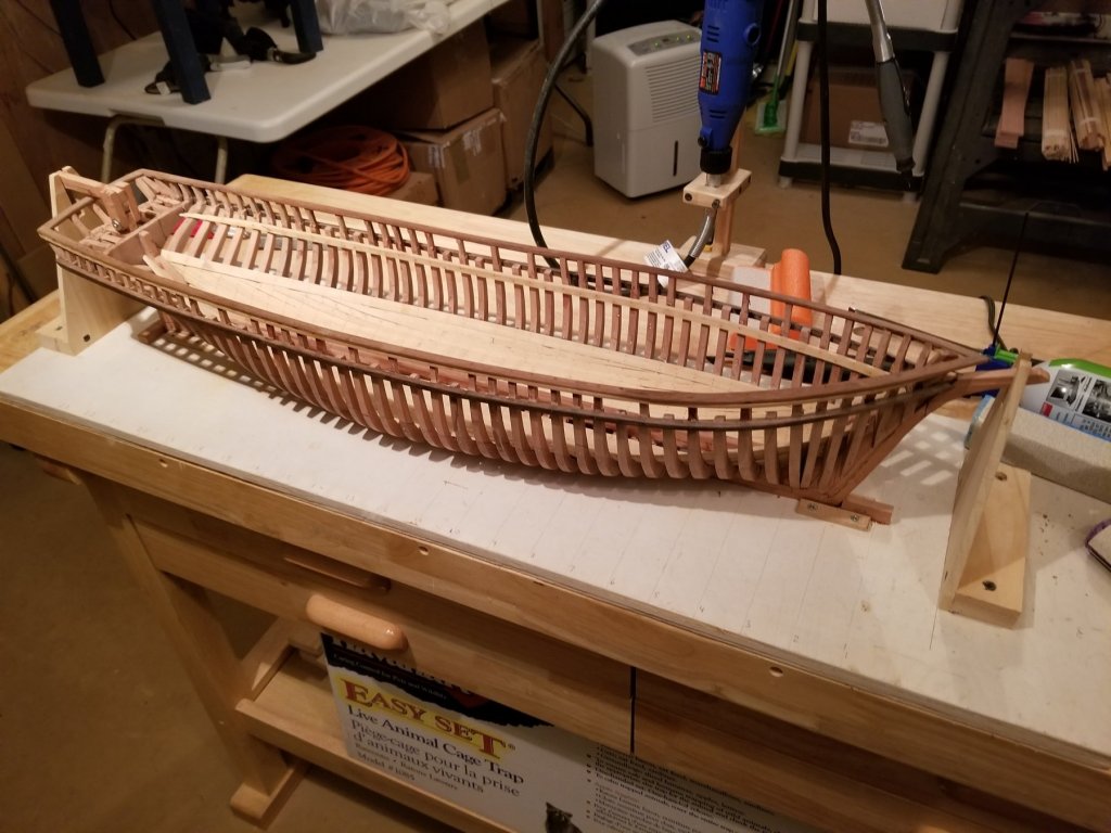
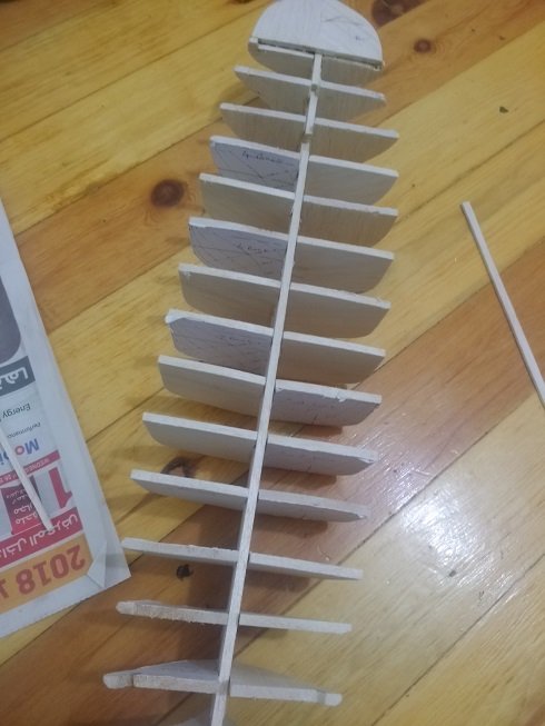
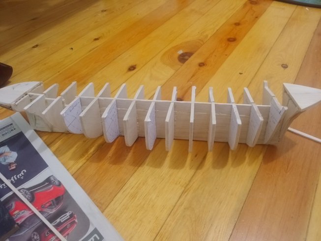
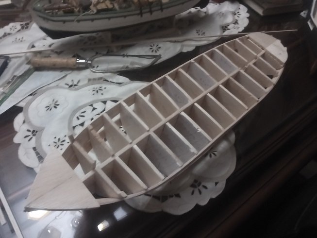
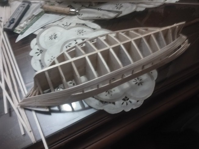
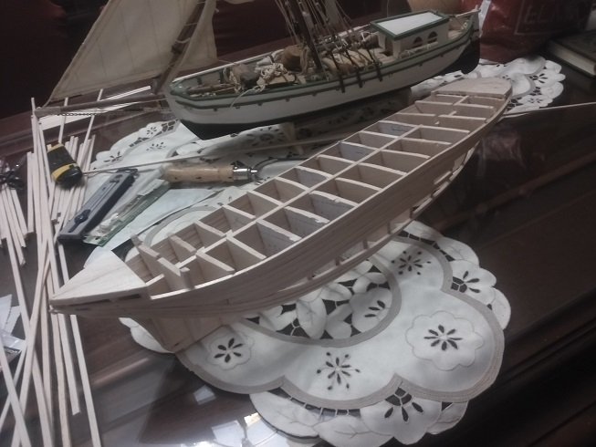
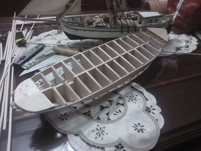
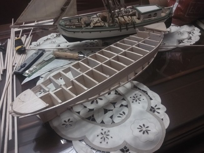
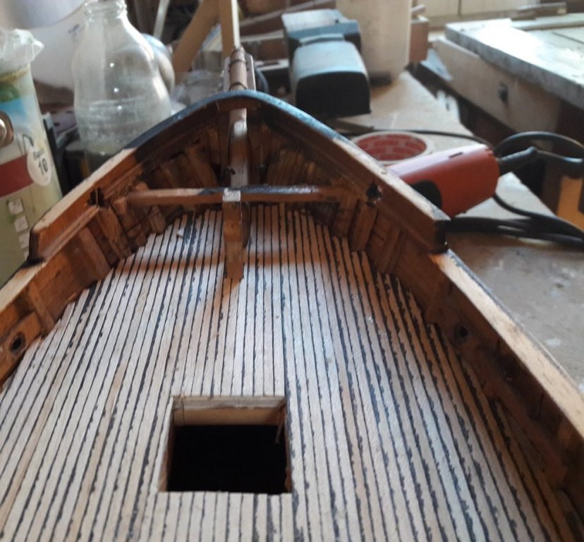
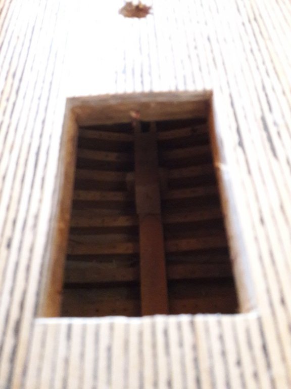
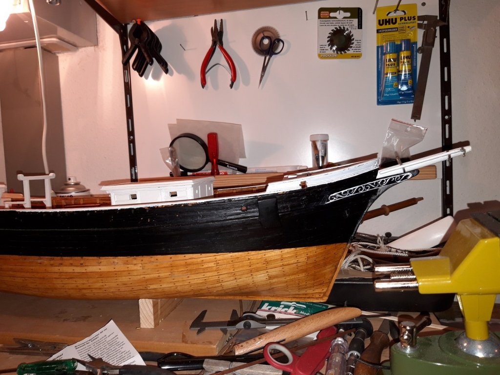
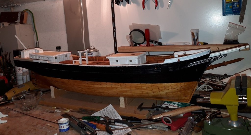
 While building the Brigantine LEON, a couple of problems and questions occured to me, which I hope to solve by sharing the progress of my work on this forum. Thanks to Doug McKenzie for encouraging me to do so, I probably wouldn't have done so otherwise. I am already busy with the hull for a long time, due to little spare time, and I didn't took photos from the beginning. So I start somewhere in the middle. I have the plans from H. Underhill, wich I purchased from "The model dockyard.com". I scanned them and zoomed them to 1/48. The quality is not very good and not very precise, but it is all I could get. So here the first pictures: I painted the hull black, I didn't know the photo of LEON at that time, showing it being painted light grey. Now I consol myself by thinking, she might have been black in her early days. The Planks freshly glued to the plywood support. View inside Building the deckhouse I am not shure about white or gold for the ornaments. It was at least just a cargo vessel. At the Moment, I am thinking about, if I should paint the bulwark white from inside or not, and how to build the railing on the aft ship section. One other Question I have ist: Where belongs the ships bell?
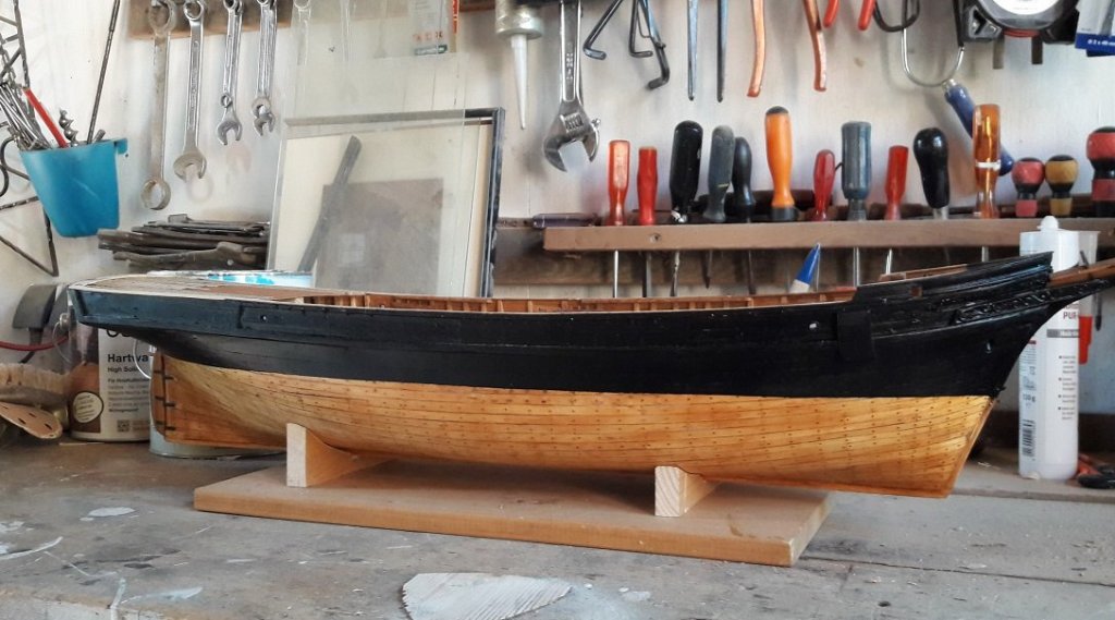

-
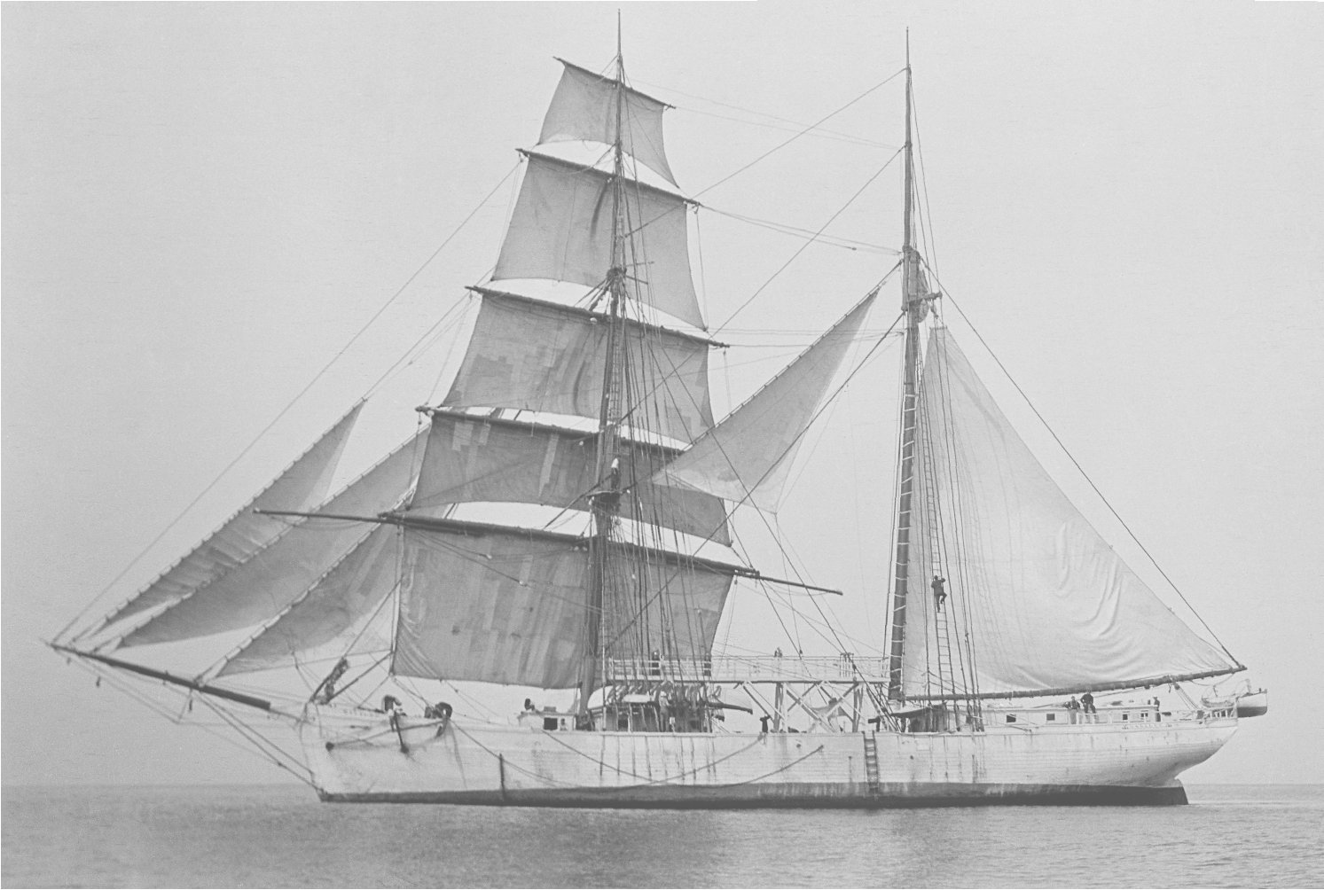
This Fall has been busy with many birthday and Christmas projects, and the resumption of homeschool with my grandchildren. So not much time has been available for work on Galilee's plans. However, a recent topic regarding gaff-rigged sails in this forum reminded me that I haven't been able to identify Galilee's mainsail type. Basically, it is a leg-of-mutton sail headed by a short spar. The not-so-all-knowing Internet claims that brigantines and hermaphrodite brigs all carry/carried a gaff-headed mainsail. Here is Galilee in all her glory, courtesy of the Carnegie Science Library: So, what is this kind of mainsail called? Thanks in advance for your assistance. Terry

- 8 replies
-
- 3
-
-
- Brigantine
- 1800s
- (and 3 more)
-
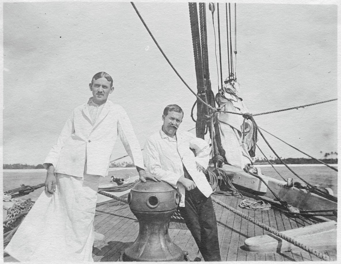
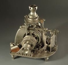
Hello, All. I've been searching for any plans/photos/schematics of a Hyde Windlass Company (HWC) hand capstan and windlass assembly. This would be sized for a 350-ton sailing merchant around 1890. The brigantine Galilee was launched in 1891 in California and seems to have been equipped with a Hyde capstan (see the photo below). Photo courtesy of the Department of Terrestrial Magnetism, Carnegie Institution, Washington DC (c. 1907) (The attire of the men is somewhat strange. The research crew's surgeon is on the right and his steward/surgical assistant is dressed for surgery.) What I really need is some information about the windlass, which was located in the open forecastle under the deck. I would like to render this equipment as accurately as possible, since it will be visible in the finished model. An entire windlass/capstan assembly has been modeled; its images are available on the Web. However, all that i have been able to find are steam windlasses, like the one shown here. Galilee's windlass was strictly manual. I have already contacted the Maine Maritime Museum in Bath, ME. They have some extensive archives pertaining to the HWC (which became the Bath Iron Works Shipyard), but their staff is limited and they haven't been able to find what I need so far. If any members live in or near Bath and would like to look into this, I would be very grateful. Terry

- 21 replies
-
- 2
-
-
- capstan
- hand windlass
- (and 3 more)
-
Hi all. Anyone know of an authoritative reference showing late 19th-century merchant pinrail diagrams? It is my understanding that belaying pin arrangements were fairly standardized by ship-type throughout most of the world, or at least within a nation's fleet, so that crew could be hired in nearly any port and would be able to serve with little additional training. I am looking specifically for the pinrail layout typical of a late-19th century, West-Coast, brigantine merchant of medium size. Any assistance will be appreciated. Terry Egolf Colorado Springs, CO, USA
- 6 replies
-
- 1
-
-
- merchant
- brigantine
- (and 8 more)
-
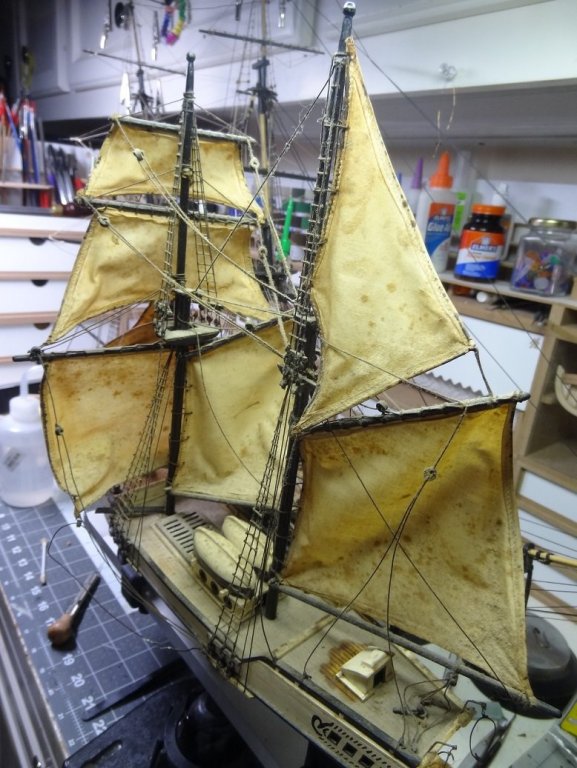
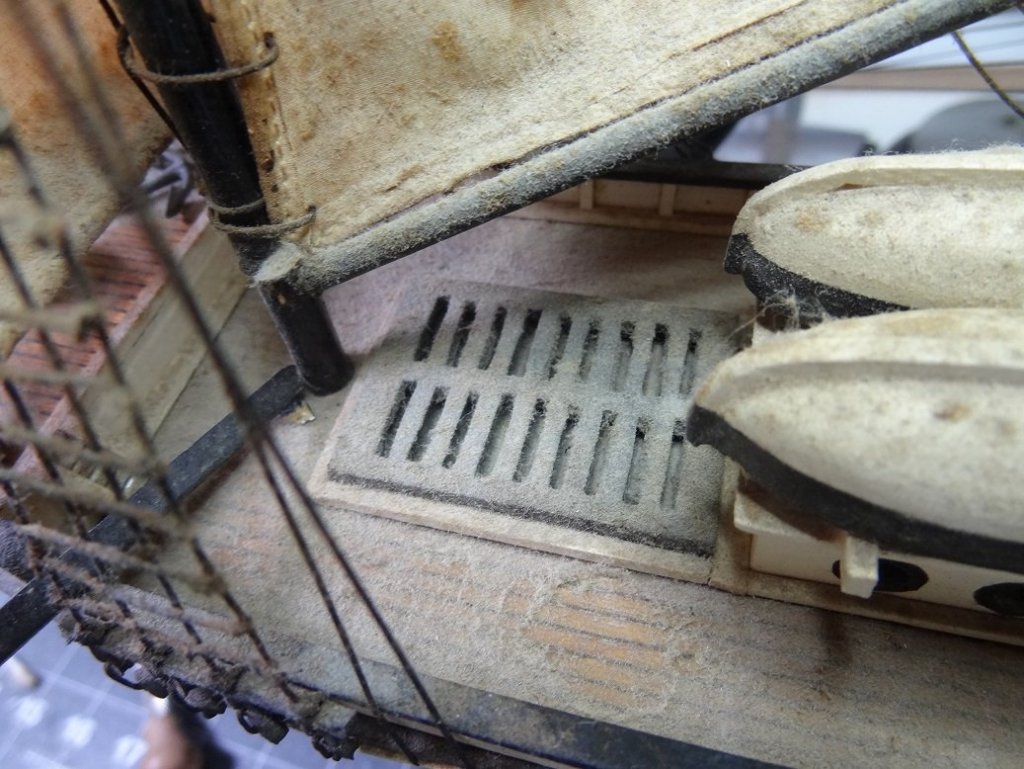
 Took my dad to see an old friend he hadn't seen in years. Way,way back we used to live in the same neighborhood. Ever since I started modeling I've had this vision - I was a child and in someone's house (some friend of parents) there was a wooden model ship in their hallway. No idea who it was. I kinda suspected it might be this old friend and sure enough it was. He still had the model and one other. This guy is almost 90 and it was over 50 years ago when I used to go to their house. Kept out in the open, you can probably imagine what they look like now. The gentleman was truly excited when I told him I built boats, and asked if I would have a look at his. Long story short, I now have 2 restoration projects. One boat is Constitution not sure of the scale but it's pretty small. The other is Hispaniola, The boat from the book Treasure Island. I guess due to the small scale they are both pretty simple with just some basic rigging. They do both have sails. Hispaniola's are set - Constitution's are furled. Overall they are not in terrible shape. Structurally sound. Most rigging is still in place or hanging off where it should be. Sails are filthy and mildewed. Everything has a thick layer of dust. Here's a few shots of Hispaniola. Never done a restore before so I have some general questions. 1. Sails need a cleaning or replacement. I imagine that means removal. For this and general rigging, do you try to save the original work or just cut it all away and replace? 2. Removing parts - no idea what glue was used but both are all wood builds. Short of prying them up, is there any tricks I should try to loosen the old glue? 3. You've seen the dust. It doesn't blow off, it doesn't wipe off with your finger. Just go with water or is there a mild solvent that might clean better? 4. No idea what type of paint was used. Overall it is in decent shape, but if I needed to touch up or paint over something what's best for that? 5. Given my memory these days I imagine the first thing to do is take tons of pix. Neither of these models is particularly nice. If you saw them at a flea market you'd probably walk right by. However, they do hold a lot of sentimental value both for the owner and to a lesser extent to me. So I don't mind putting some $$$ and elbow grease into fixing them up. I don't see a lot of posts about restores here at MSW. If you know of any other resources I would appreciate hearing about them. Oh man, what has he done now
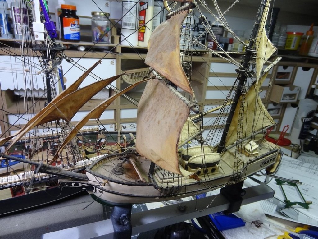
-
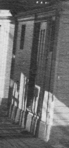
Need some help interpreting what I am seeing here. In the attached photo of Galilee's middle deckhouse port side, there is evidently a sliding door mounted on wheel tracks top and bottom. Here are some questions: How was such a door made reasonably weatherproof? Would there be water stops built into the frame to prevent major water intrusions during boarding seas? Would the door handle/latch be a lever or just a hand grab like a staple? As you can see, the photo is pretty muddy where a handle would be. There is a suggestion of a vertical metal rib along the forward edge of the doorway, which might be a water stop. Like all sliding doors on ships in my experience, there was probably a standing latch when the door was fully open and a latch when it was shut. I have no idea if technology of the late 1800s would have produced a mechanism that would operate both latches. If anyone has reference photos or other images of such an installation, I'd appreciate seeing them. Thanks. Terry
- 11 replies
-
- 2
-
-
- 19th century
- Galilee
- (and 6 more)