Search the Community
Showing results for tags 'drilling'.
Found 2 results
-
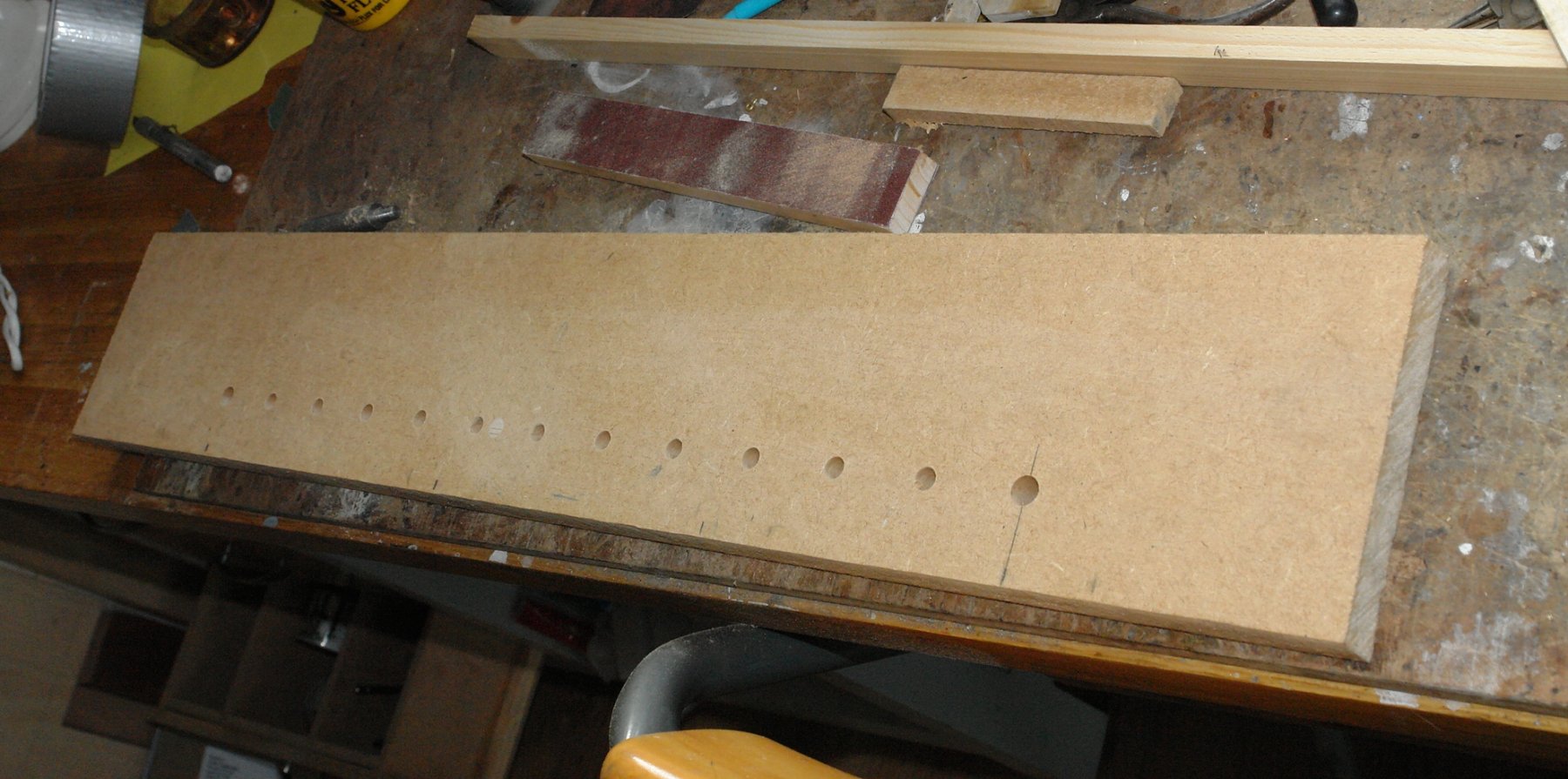
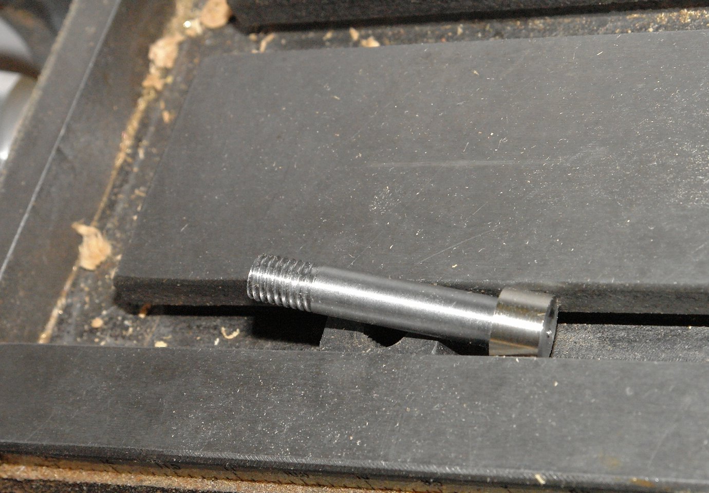
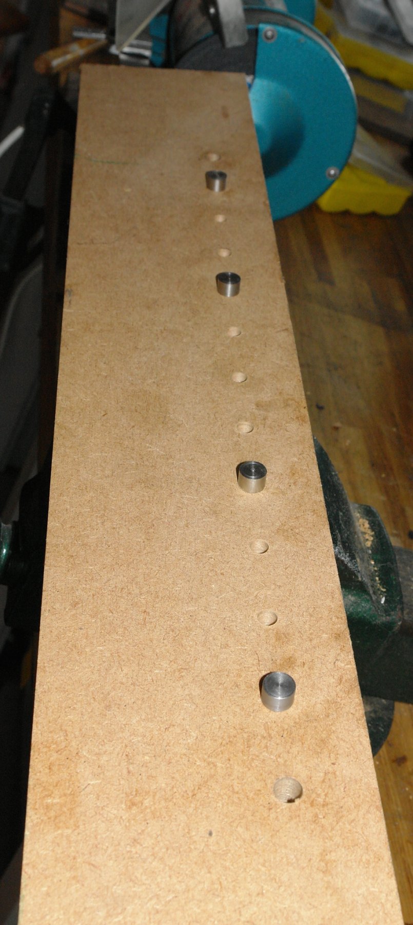
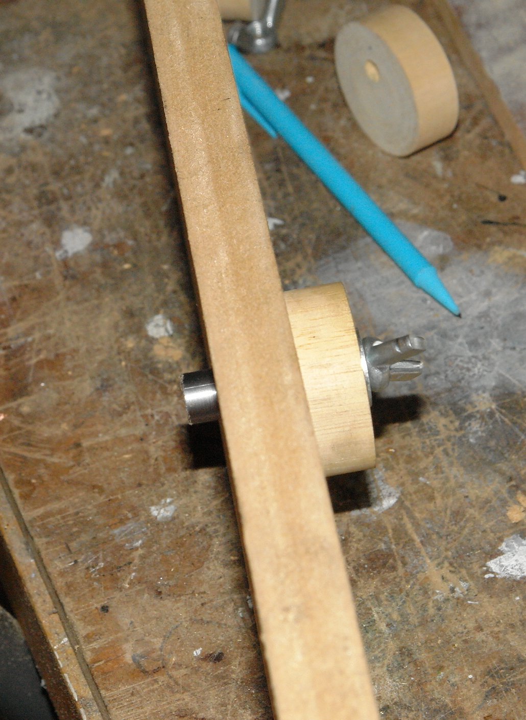
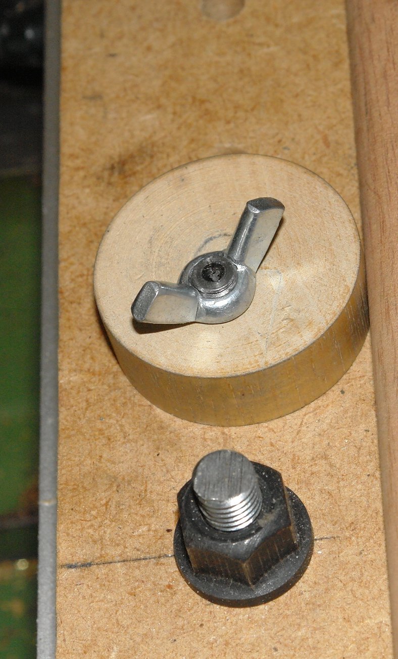
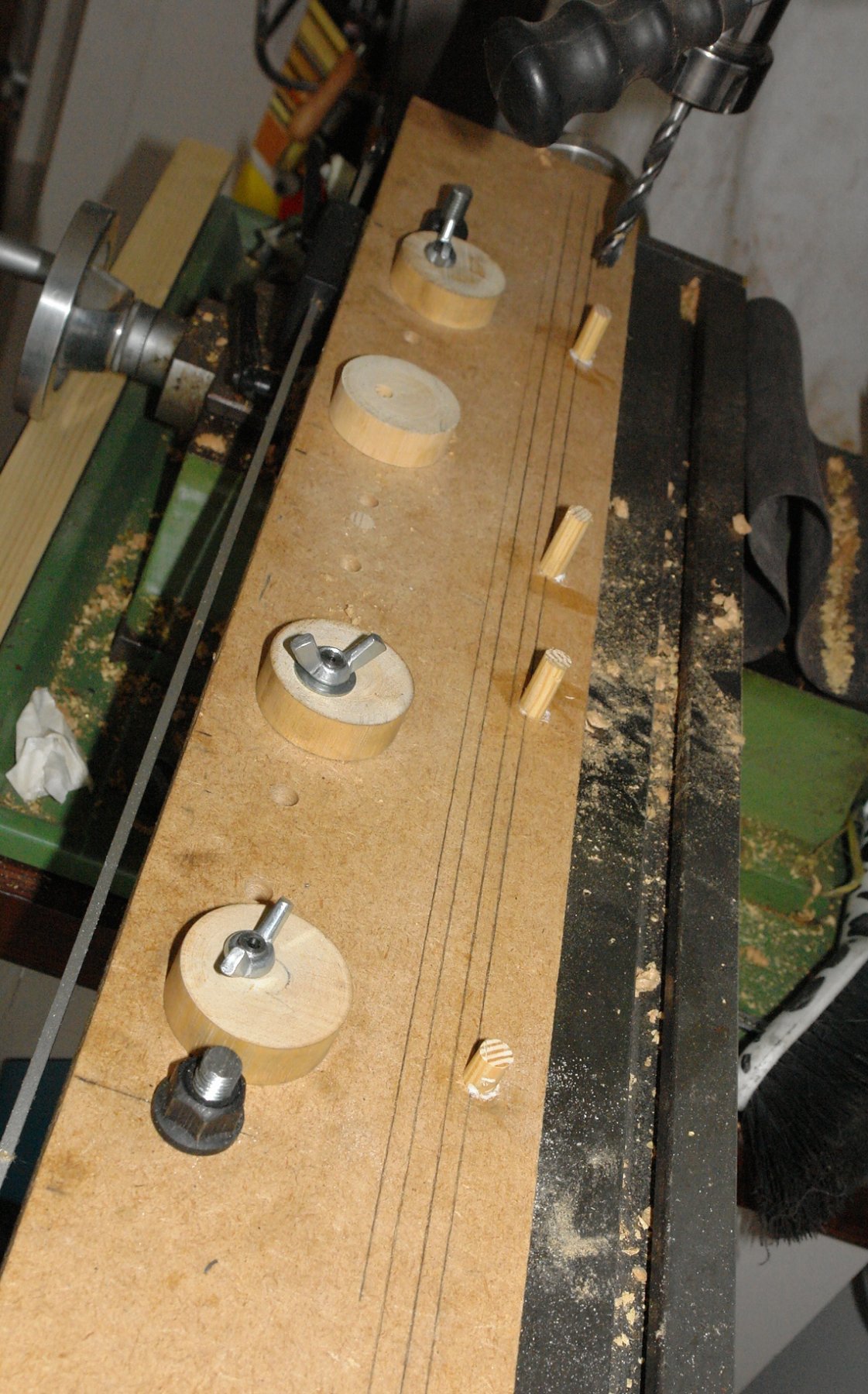
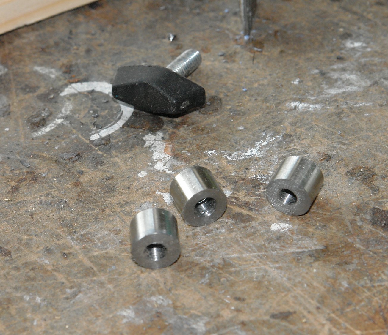
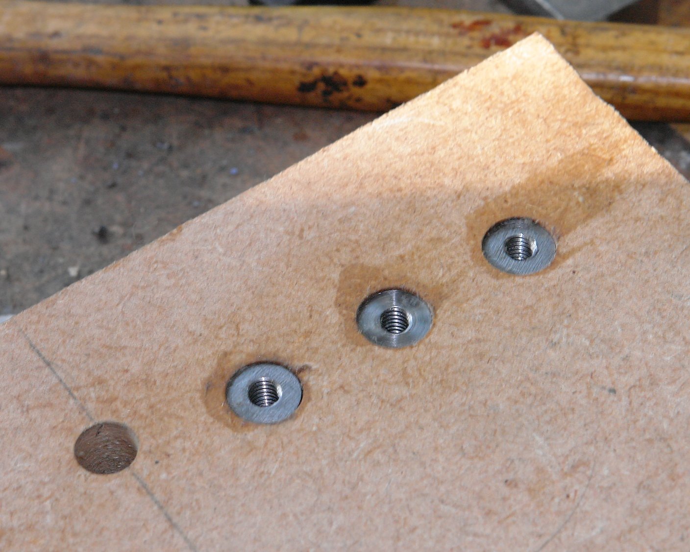
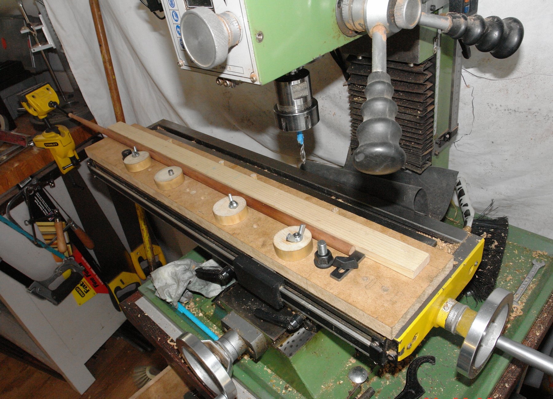
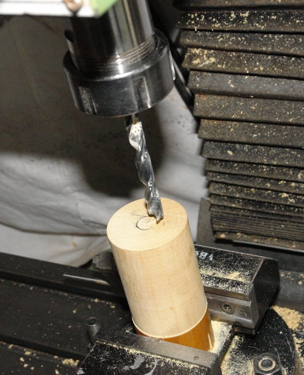
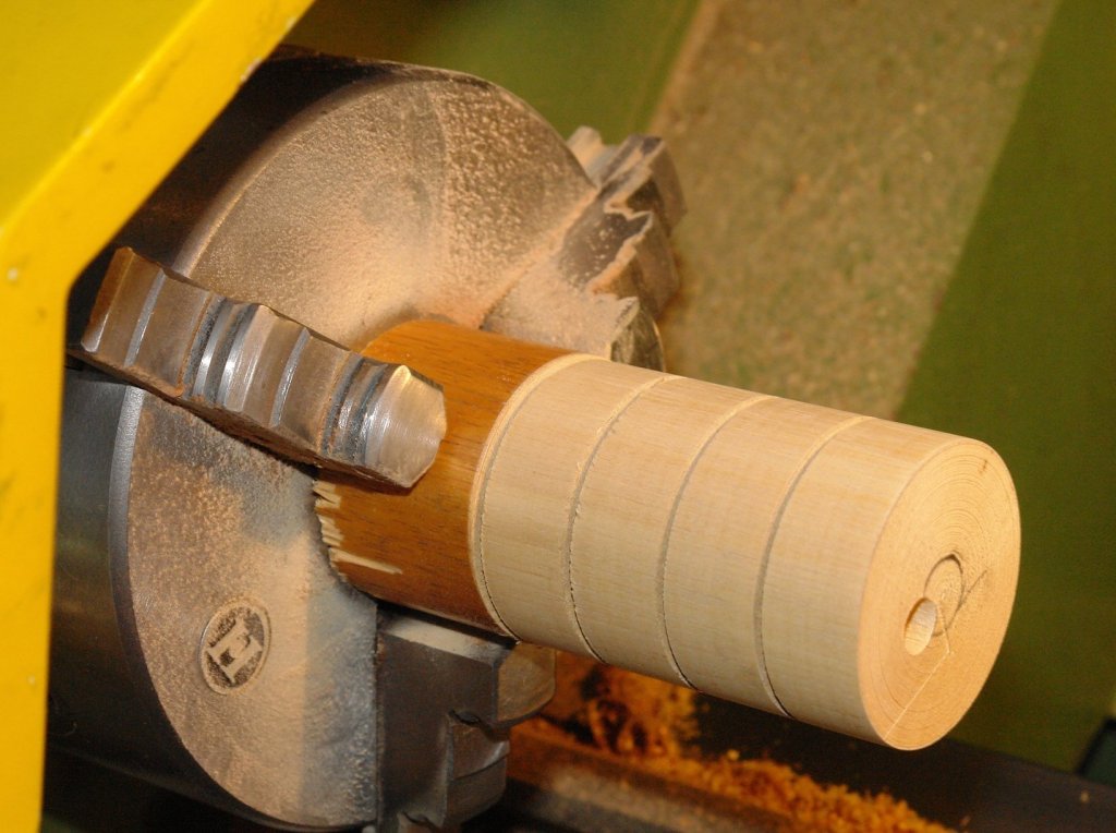
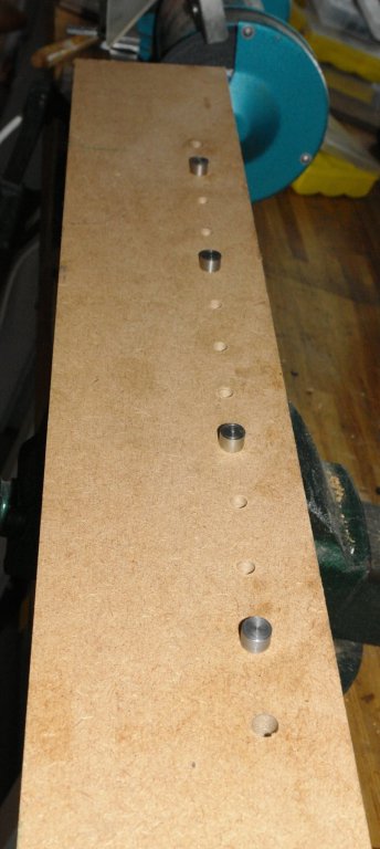
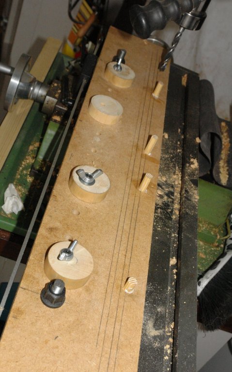
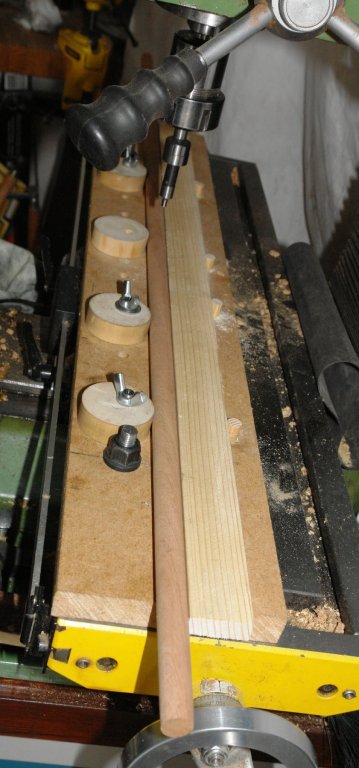
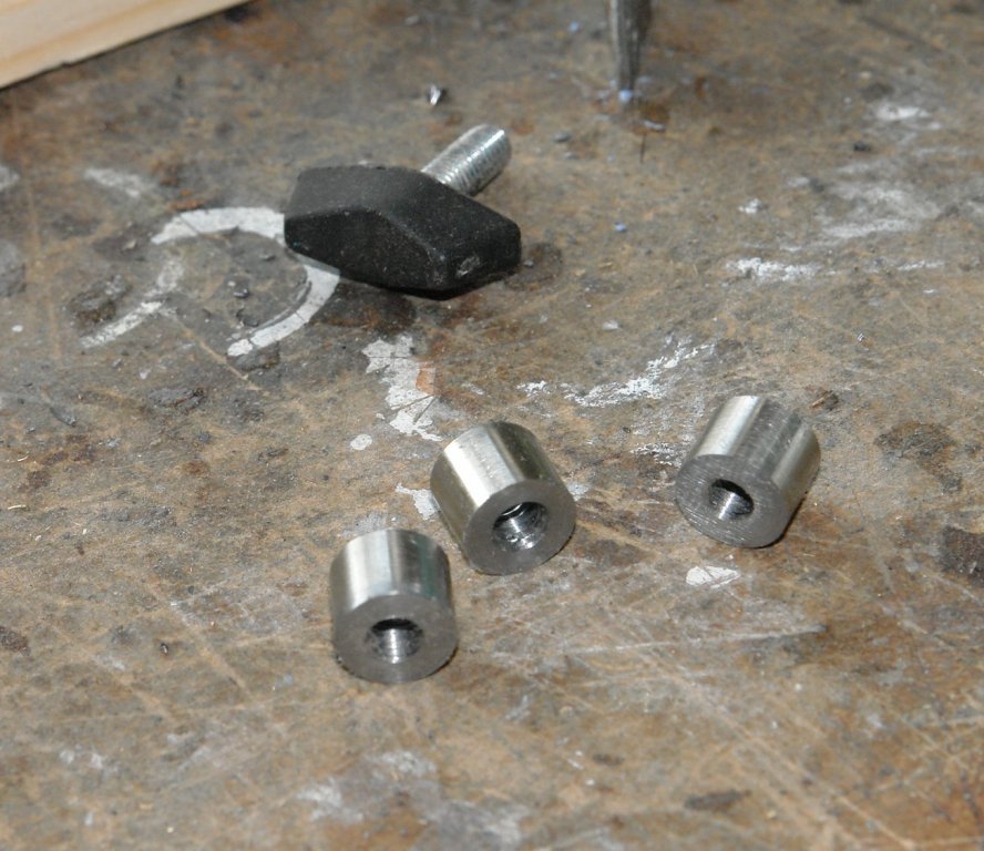
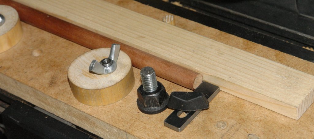
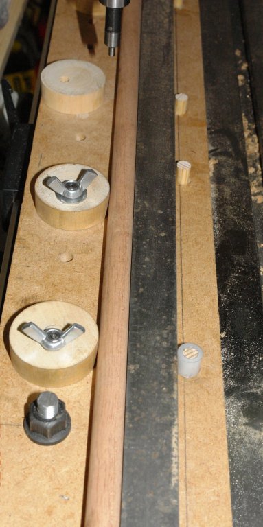
 In the past I have constructed many ad hoc fixtures to enable the accurate machining of masts, spars, yards, booms etc. I decided to have a go at making something more versatile that would work for items of different shapes and sizes. Having made it it seems to work well so I thought it would be worth sharing. I started out with a set of design aspirations. For ease I will refer to "masts" rather than go through the full range of parts each time. 1 Provide solid clamping along the length of the mast. 2 Locate / relocate on the milling table without the need for alignment / set up. 3 Positively locate and relocate the mast so that I can easily remove and replace it on the mill. 4 Clamping devices not to mark / damage the mast. 5 Clamp parallel and taper masts. 6 Clamps to be easy and quick to operate. I started with a clamping concept based upon eccentric circular cams and the build started by cutting a piece of 3/4" MDF to sit on the milling table. I used the mill to accurately drill a series of holes along the length of the MDF to take the cams. The cams themselves were turned (circular) from hardwood. An eccentric hole was drilled along the axis of the cams before they were separated. The cams are mounted on the MDF using a pin. The pin protrudes below the bottom surface of the MDF and the protruding part is cut to a diameter .001" smaller than the slot in the milling table. Once the pins are pushed into the MDF they give positive and repeatable location on the milling bed. The top of the pin locates the cam which is locked by a wing nut. The additional holes allow the cam positions to be varied to suit the mast being worked on. Holes at either end of the MDF take the "T" nut bolts which attach the MDF to the milling table. The MDF was then placed on the milling table (located by the pins) and a row of 4 holes were drilled parallel to the pin holes. Into these holes were placed accurately made dowels. These dowels provide the "fixed" support against which the cams clamp. I think this will become clearer in later photos. A simple piece of wood is then placed up against the dowels. This forms the face against which the mast is clamped. In the following picture a mast is clamped in place. Because the cams act as a finely tapered wedge hand rotation is enough to very rigidly hold the mast. The cams give a lot of flexibility on the diameter of mast that can be held - .200" to .700". But larger is possible by using a narrower wooden strip. At this stage I checked the alignment of the mast to the axis of the mill. The run out was .0015" over a 12" length. Much better than I expected. I did however need an end stop to control the position of the end of the mast. This was relatively easily achieved and for good measure I included an option for 3 positions. See Photos:- The solution to dealing with taper masts is straightforward but does require a bit of trigonometry. The taper is achieved by changing the diameter of one of the fixed dowels. This is done by making a collar to fit over it. This gives a triangle the base of which is the distance between the first and last dowels and the "opposite side" is the thickness of the collar wall = (outside diameter - inside diameter)/2. In the last picture I replaced the wood strip by a steel bar - but this proved to be un-necessary. I still have a few bits to develop but I think thats enough for now - except for the mystery of the missing wing nut!!!!!!


-
I started my Revel 1/96 Constitution when my youngest was 4. It was slow going and I used to joke that I'll have it done in time to give it to her as a wedding present. I eventually just put it away as it was a little overwhelming. Well she's 23, and while she doesn't have a serious boyfriend, I'd like to fulfill my committment when the time comes. So it's unpacked and I'm sitting here and I'm stuck exactly where I was before. Except now there's the Internet. :-) So in brief, I can't figure out how to get the string through the tiny cannon door holes. Do you just drill very carefully? Use a hot needle? Something else? I'm sure there's some technique. Any ideas are gladly accepted! Thanks!