Search the Community
Showing results for tags 'radio'.
-
 I think I mucked up, I thought I was starting a Build Log, but it appears my first Post was in the "Introductions" folder. So I will now try and start a Build Log here. And I'll start again. Hello, my name is Wayne and this is my first Post here, I joined the group a couple of weeks ago. I’m 74 and in Melbourne Australia and I’m currently building the Billings African Queen. And this has been a quest of mine all my life, I saw the movie as a very young boy when my parents went to the Drive In Pictures, around 1953. And I have always remembered different scenes from the movie. So I have now finally got around to building it, and with live steam. And intend to have RC for the steering, I will just let the steam engine chug along. Yea being an open launch I don’t want to have servos etc spoiling the look of the model. I hope to hide a small servo for steering under the rear seat. And the vacuum formed plastic hull will be water tight when on the water. But I’m thinking of planking over the hull, I hope that will be OK. And I must say, the most important tip I picked up while researching the build was to leave the top extra mounding there, not cut it off until the hull internals and deck were completed. I have the ‘Miniature Steam Models’ plant #4034 here to go into the boat. I must thank gjdale, (Grant) for guiding me to that plant, and it looks spot on for the Queen. And MSM are in Melbourne too. Just ordered 2 universals, 5 to 4mm, and a brass prop from ‘Float a Boat’, also in Melbourne, and they were very helpful. Will have to see if I use the Billings prop shaft or have to buy a longer one.
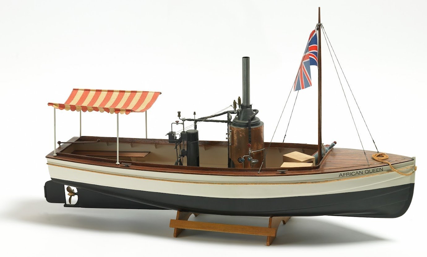
- 30 replies
-
- 6
-

-
- African Queen
- Billing Boats
- (and 2 more)
-
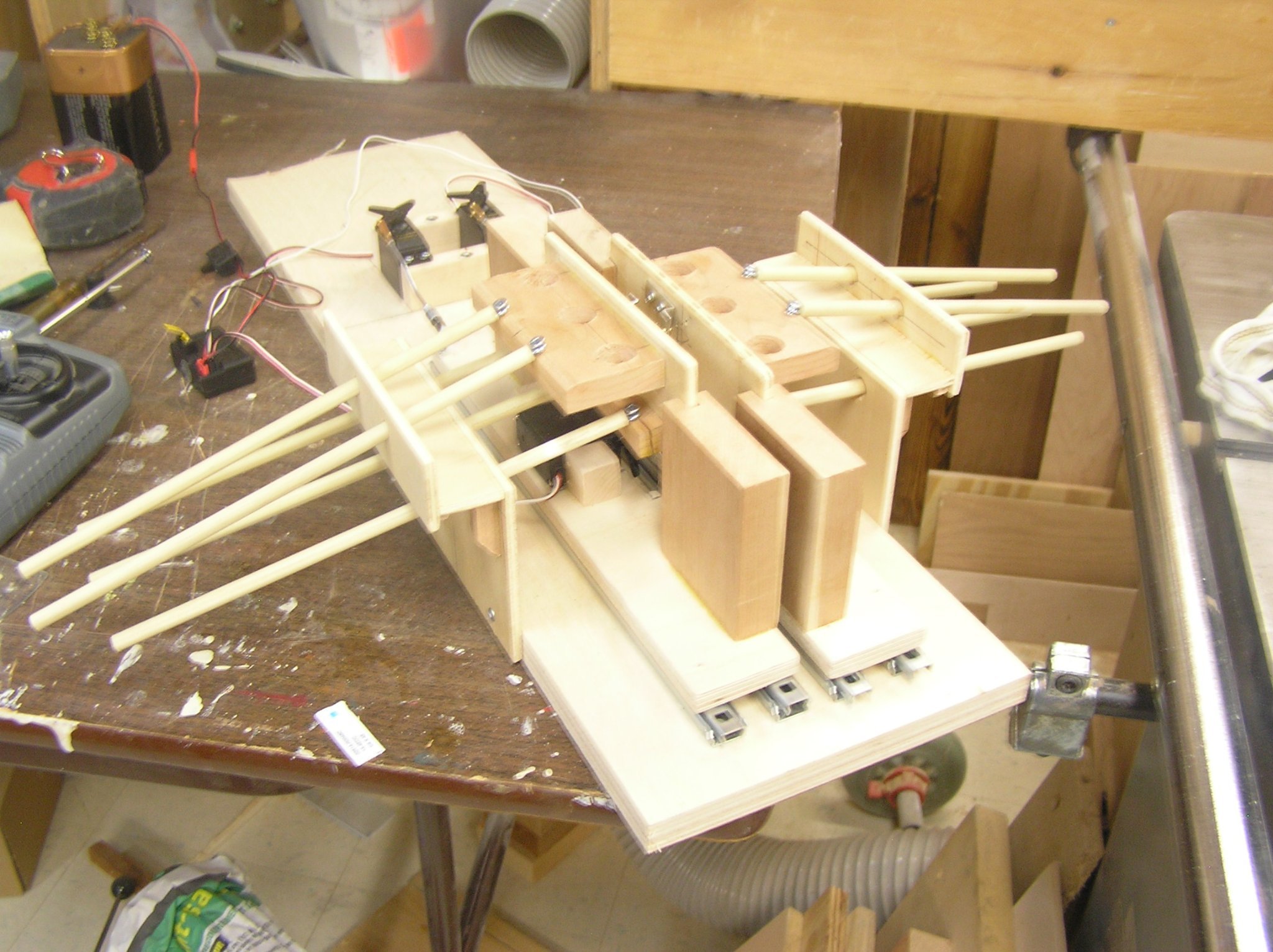
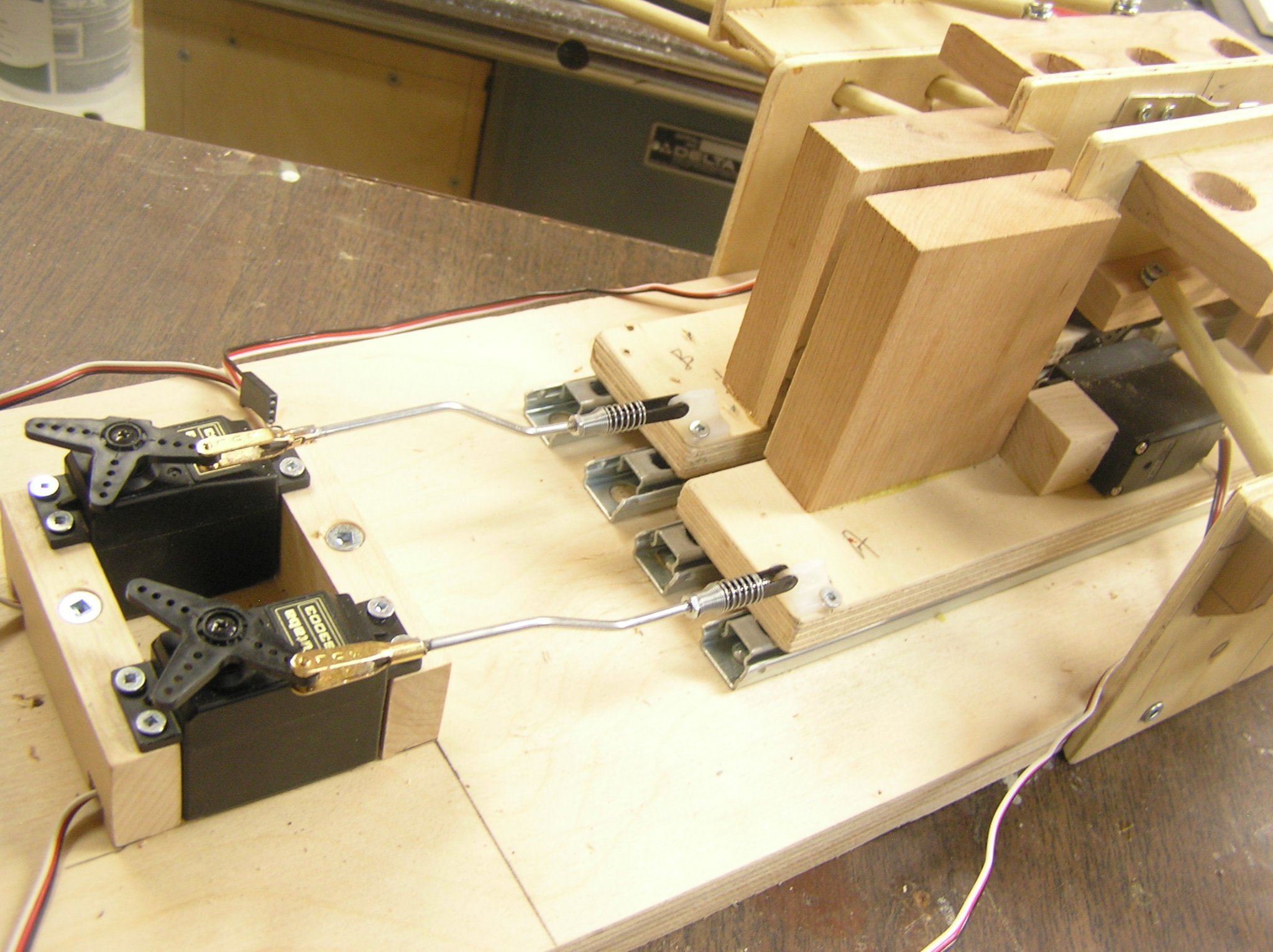
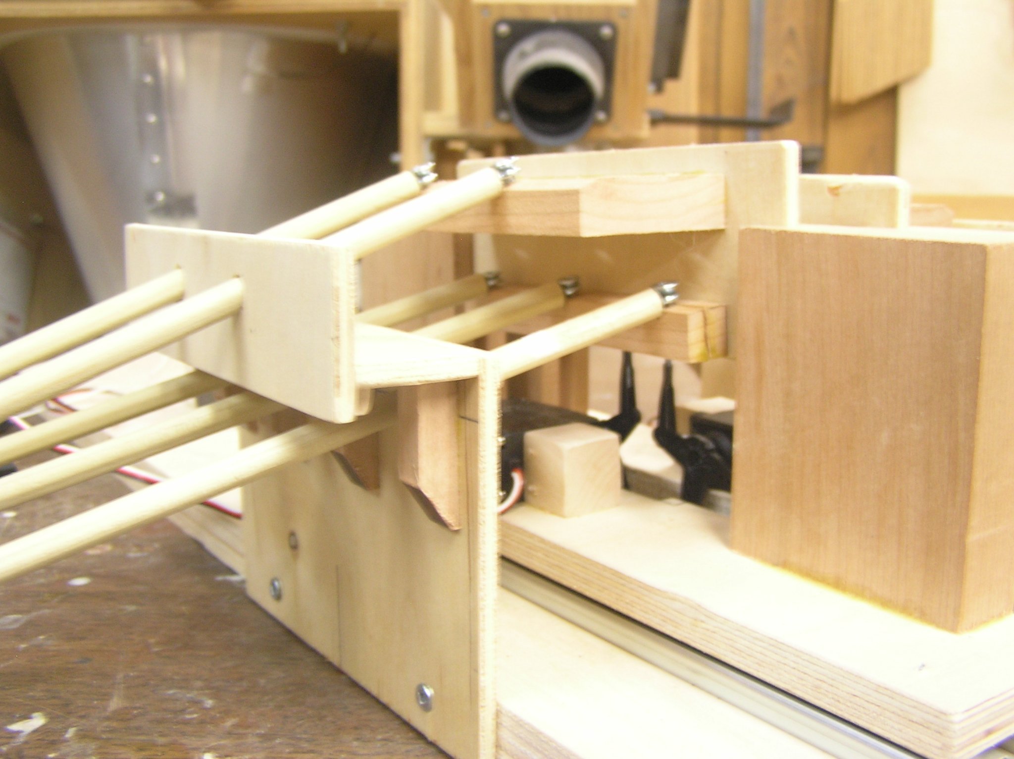
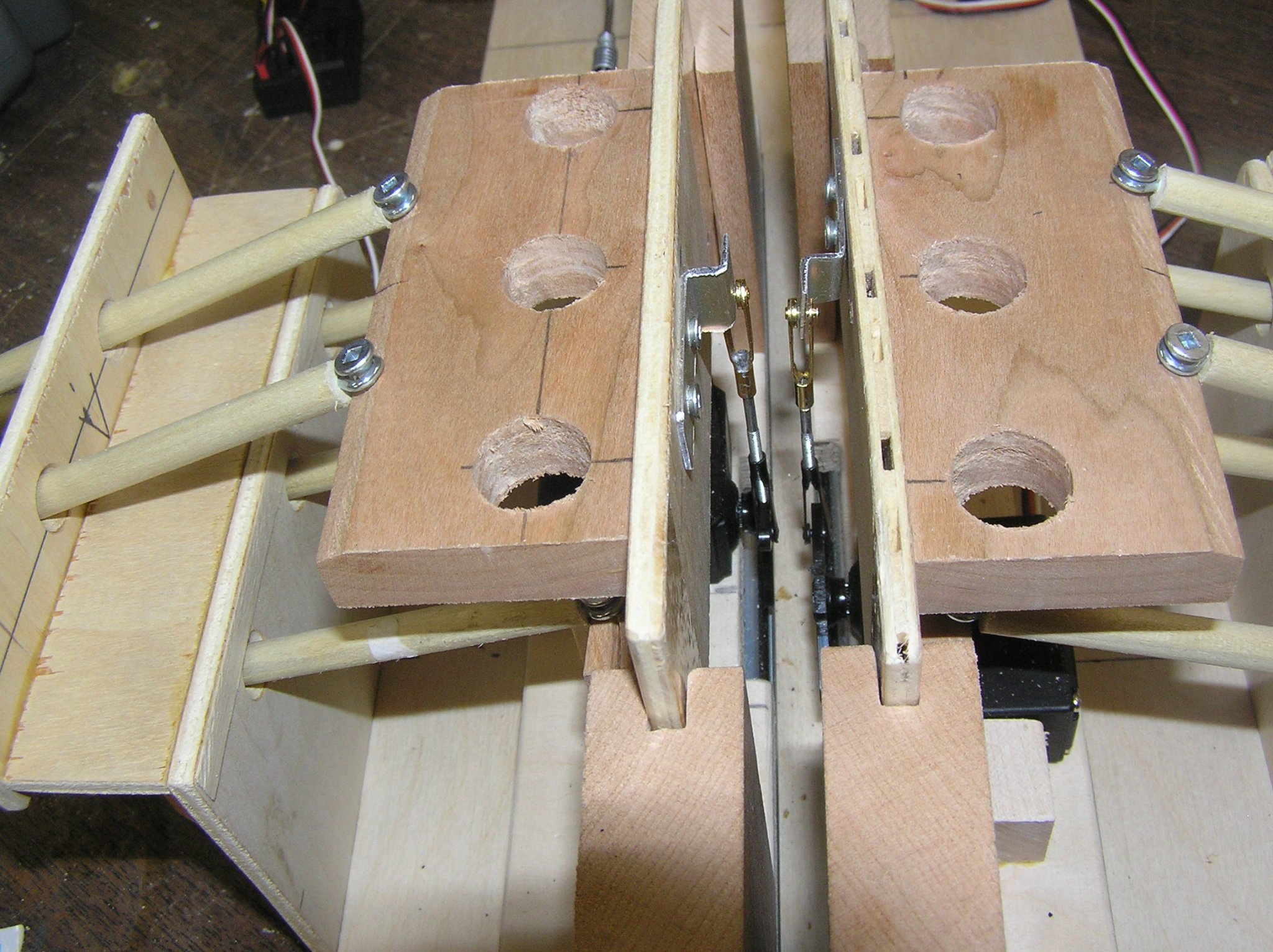
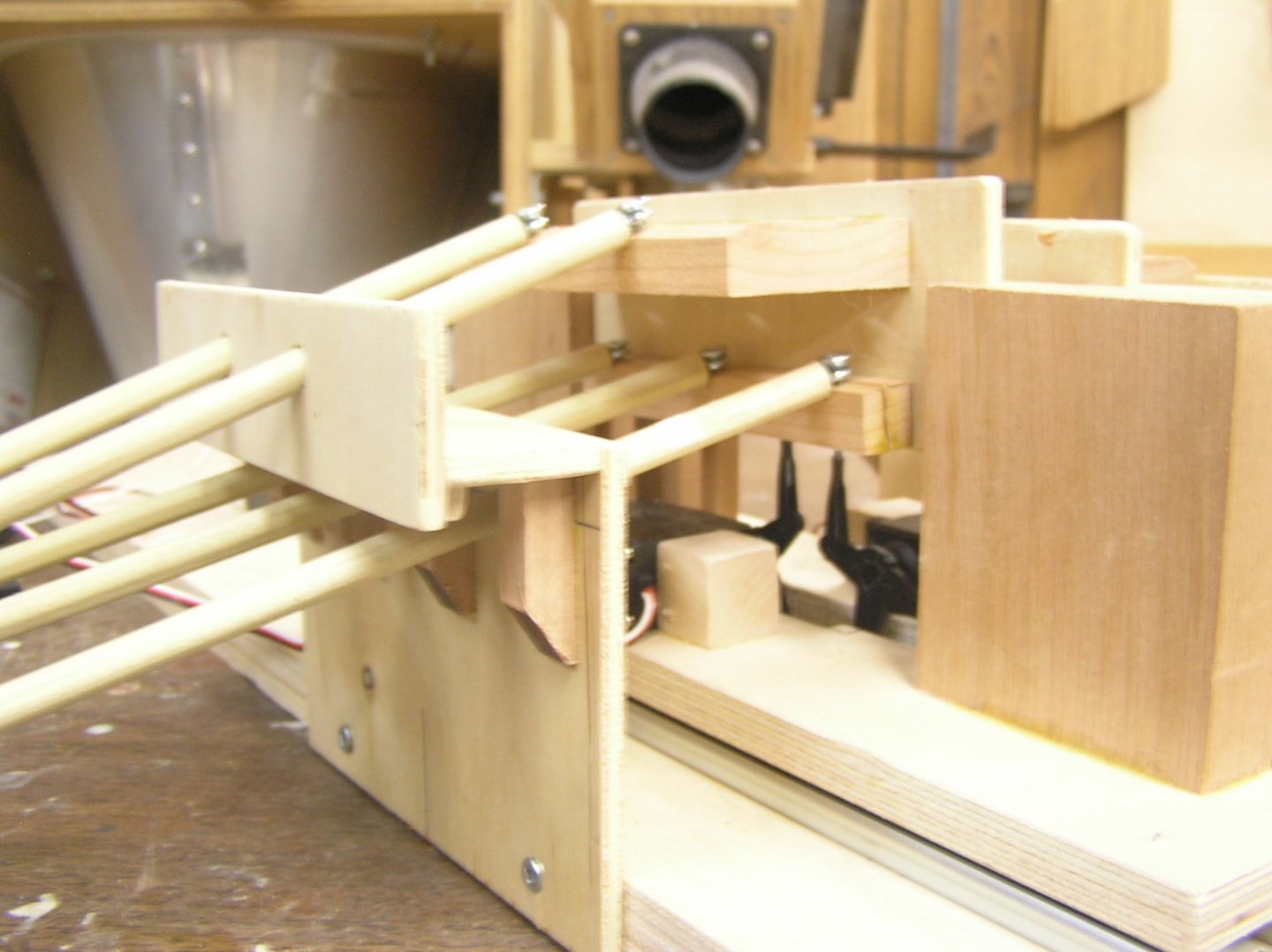
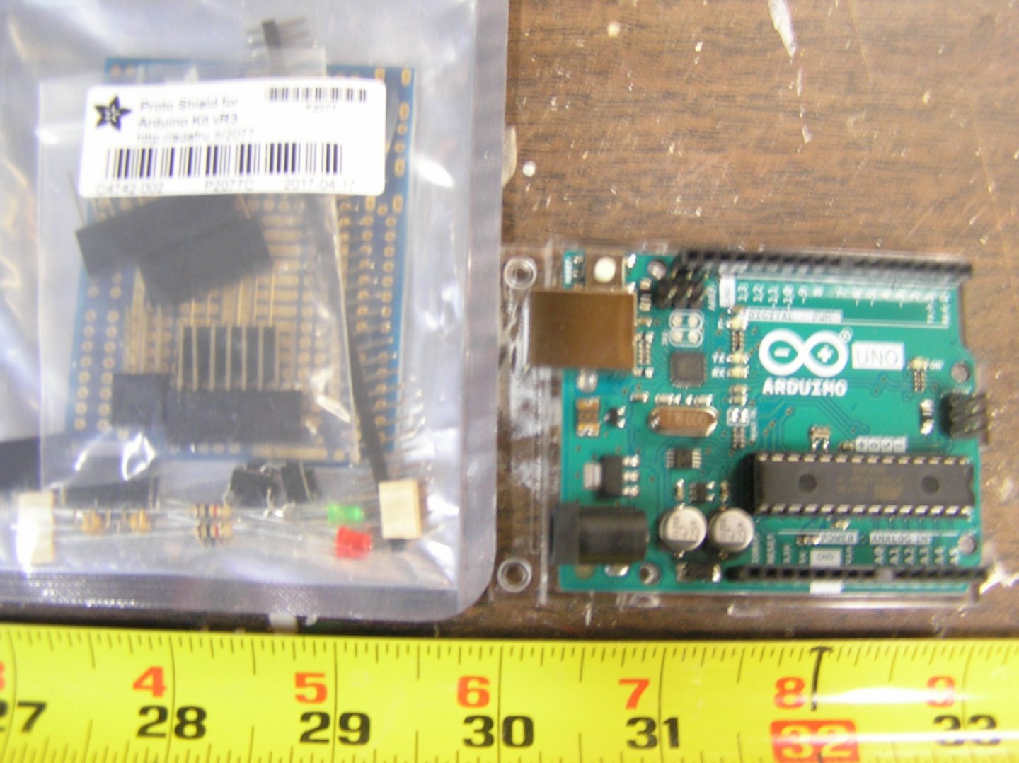
 IMPORTANT NOTE: This build log is a title change from the previous title "Arduino Rowing Mechanism for RC Galley". The log was originally opened to record my progress on making a servo-driven mechanism to move banks of oars in a realistic manner, for the purposes of building an RC Roman galley, propelled by her oars, at 1/32 scale. An Arduino "Uno" interfaces to the RC Rcvr and four servos which drive the oars on two sides, with author-written software to control the oars according to the "throttle" and "rudder" signals from the Rc Transmitter. Software was developed using the Arduino "Integrated Development Environment" (IDE) and a prototype test jig containing several oars per side. The log got pretty long in the end; readers interested only in the actual ship development should jump to post 164 on pg 6, bypassing the tangled history of the software and rowing mechanism development. Those who might be interested can read the initial pages. *************************************************************************************************************************************** *************************************************************************************************************************************** START OF ORIGINAL BUILD LOG: Lately I have become interested in ancient Greek and Roman galleys, and have been toying with the idea of making one for RC. When I saw Richard Braithwaite's demo mechanism I became even more intrigued with the idea. As opposed to using electric motor(s) and some sort of mechanical drive with pulleys and chains I thought a better way might be to use hobby servos for the job; one servo driving the forward/backward sweep and a second driving the up/down motion of the oar loom beam (per side). And rather than having a four channel set and continuously twiddling the sticks to make the oars row, it seems an ideal application for an Arduino microcontroller running custom software. In this scheme, the Receiver output servo signals for "throttle" and "rudder" are connected directly to, and read by, the Arduino. The rudder signal is also connected to the rudder servo via a y-harness. Arduino software controls the four oar drive servos. This servo-driven scheme has several advantages over electric motor mechanical drive: (1) Since software is driving all four servos, it is simple to keep them all moving in sync, whether going forward, backward, or reversing oars on one side during a turn, at any given speed, (2) Software can use the "rudder" input to decide when to move the two sides differently; for example a slight course correction can be ignored (by the oar servos); a middling rudder angle could halt the oars in the water on the inside of the turn; a large rudder angle could reverse the oars on the inside of the turn (while keeping the start and end of the stroke synchronized on both sides). (3) When slow speed is desired, the software can shorten the stroke as opposed to an electric motor drive which still executes a full stroke making it look like the oarsmen are stretching right out and pulling back, all in slow motion. (4) Software can provide a slight pause at the end of each power and return stroke, as would occur naturally as the oarsmen absorb then reverse the inertia of the oars. (5) Software can make the return portion of the stroke faster than the power portion to better represent actual rowing. The shape of the overall stroke is formed by the dynamic relative movements of the sweep and lift servos; any shape can be formed, eg rectangular, oval, eliptical, circular, by performing a bit of math in software to calculate the next servo position writes. In short, the oars can be made to do whatever one wants, and is capable of writing code for. I decided to build a test jig for code development. Each side of the jig has 5 oars in a bireme arrangement; I'm thinking of making either a Quadrireme (88 oars in two remes of 22 each side), or a sextere (120 oars in two remes of 30 each side). See Michael Pitassi's book "Roman Warships". Here are a few photos....... Each side's "platform" slides on two Slim-Line drawer slides which only occupy 3/8" of vertical space. Much less than ServoCity's X-beam with mini rollers etc which was my first idea. The vertical chunks of wood at the platform ends are dadoed to let the oar beam slide up and down; the ends of the oar beams I wrapped in packing tape to make them "slippery". In an actual model I'd replace these with ServoCity's SS shafts and linear bearings. The dummy oars pass through a "hull section" which defines the spacing between the two remes' "tholes". Here we see the two servos which drive the platforms back and forth. Here we can just see the two servos which drive the oar beams up and down. Here is the Arduino board, and a prototyping board which will be mounted on it and contain connectors for the receiver inputs, servo outputs, etc. My simple two-channel RC set can only drive one side right now, without the Arduino. Tried to upload a video but no joy; will try again later.


- 502 replies
-
- 7
-
-
- Quadrireme
- radio
- (and 1 more)
-
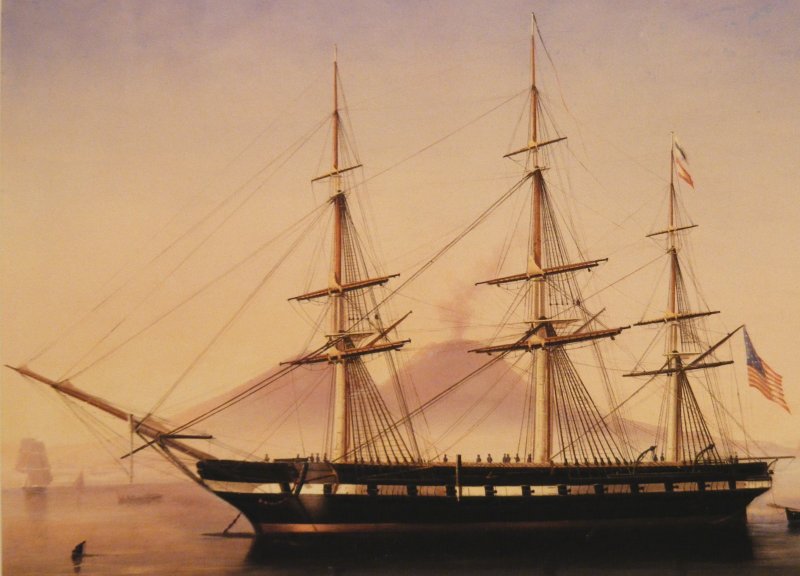
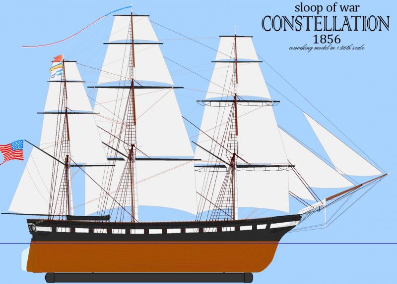
 Inspired by a large RC model of the Rattlesnake featured in an issue of Model Ship Builder magazine, I looked around for a subject to built and decided to built the ship in my own back yard, the sloop of war Constellation tied up in Baltimore's Inner Harbor since the mid 1950's. Some video of Rattlesnake Constellation was a sloop-of-war, of 22 guns, designed by John Lenthal, and built in 1854 by Gosport Navy Yard at Norfolk, Virginia; the last US warship designed and built to operate under sail alone. For a long time she was believed by many to be the old frigate of 1797, rebuilt and moderized, and that debate has raged in the maritime history community for decades. Her lines and sail plan were acquired from the National Archives where I got to handle the actual hand drawn documents. I decided to build her as she appeared in a portrait by deSimone when she was in Naples in 1856 and still a new ship. Her lines were drawn in 1:36 scale, which was perfect, giving a model: Beam: 13-5/8" (34.713 cm) Length over the rig: 96" (243.84 cm) Width over the rig: 36" (91.44 cm) ~ Main yard w/o stuns'l booms. Length on deck: 61" (154.94 cm) Length between perpendiculars: 59-1/8" (150.178 cm) Draft, without ballast keel: 7" (17.78 cm) With 3-1/2" ballast keel: 10-1/2" (27.94 cm) Height bottom of keel to main truck, without ballast keel: 65" (165.1 cm) With ballast keel: 69" (175.26 cm) Sail Area: 2,807.01 square inches in 17 sails (19.5 sf, 18,109.7 scm, 1.8 sqm) This log will cover my work on this model since it began in 1999 up to where it is now. Author's Note: This is a log of how I am building this model, not a guide to how a model such as this ought to be built. It's full of fits and starts, changes of mind, errors, re-do's, more error's, a few mistakes; and somehow, despite all this, it seems to be becoming a working, sailing model that actually looks something like it's namesake. The director of the actual ship recognized it on first sight - I take that as a good sign! If you're considering taking on a project like this, please, please, don't let this build log deter you - it's not nearly as difficult as I make it seem. Just take away from it that which helps you along, and ignore the rest.
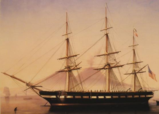
- 524 replies
-
- 4
-
-
- sloop of war
- constellation
- (and 9 more)
-
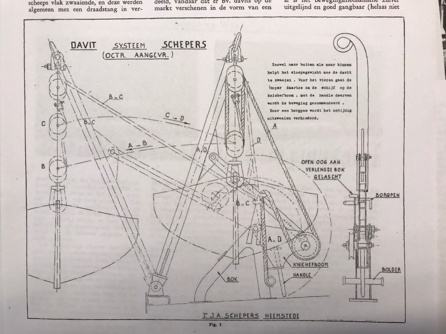
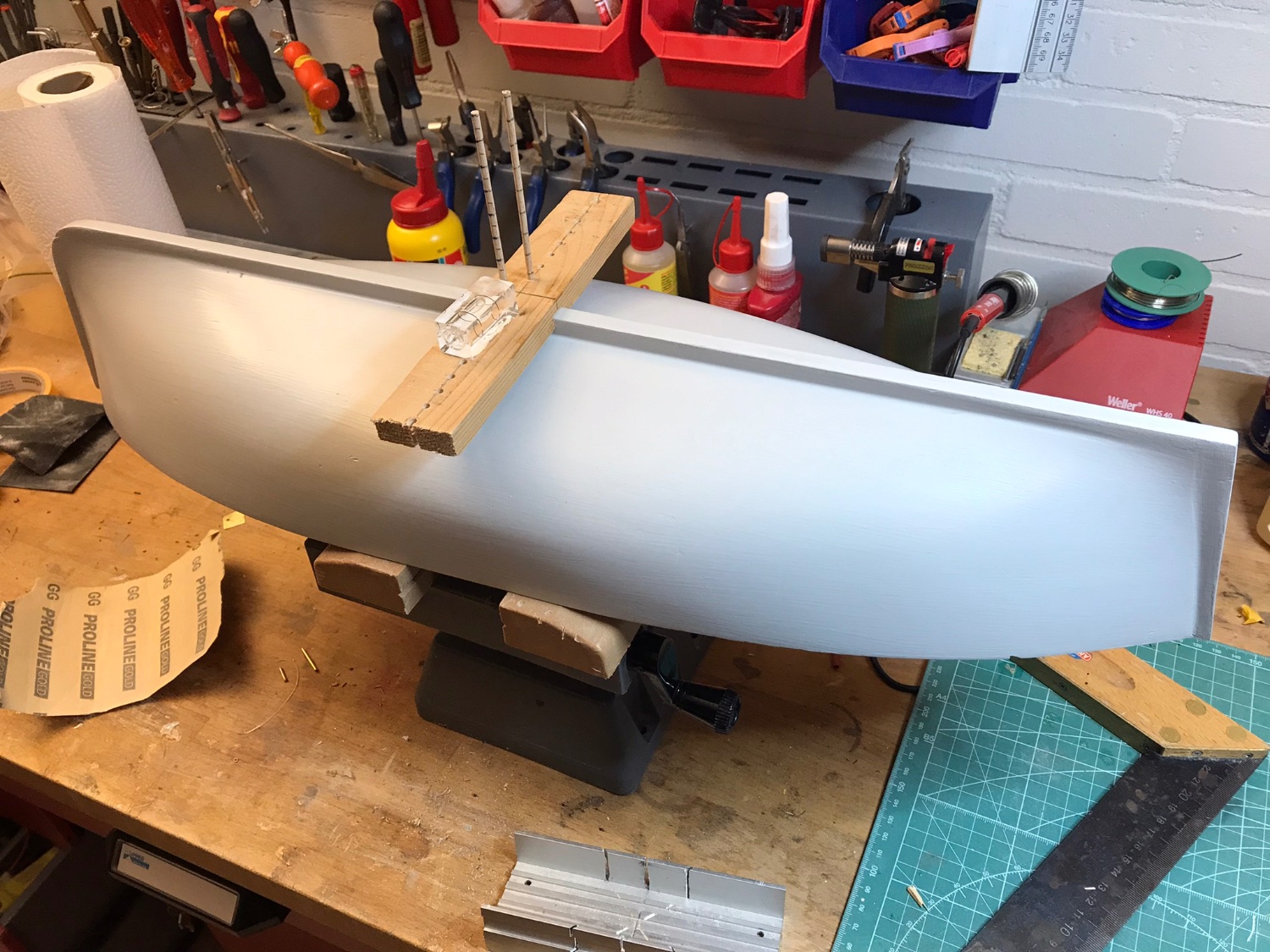
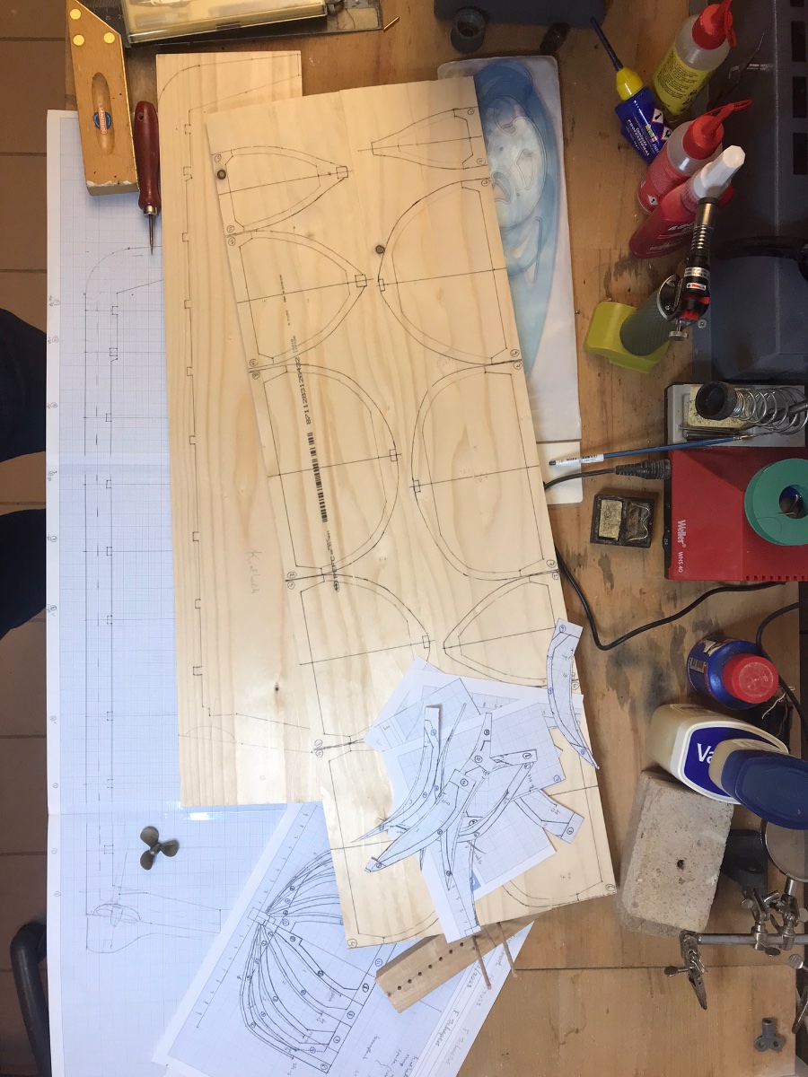
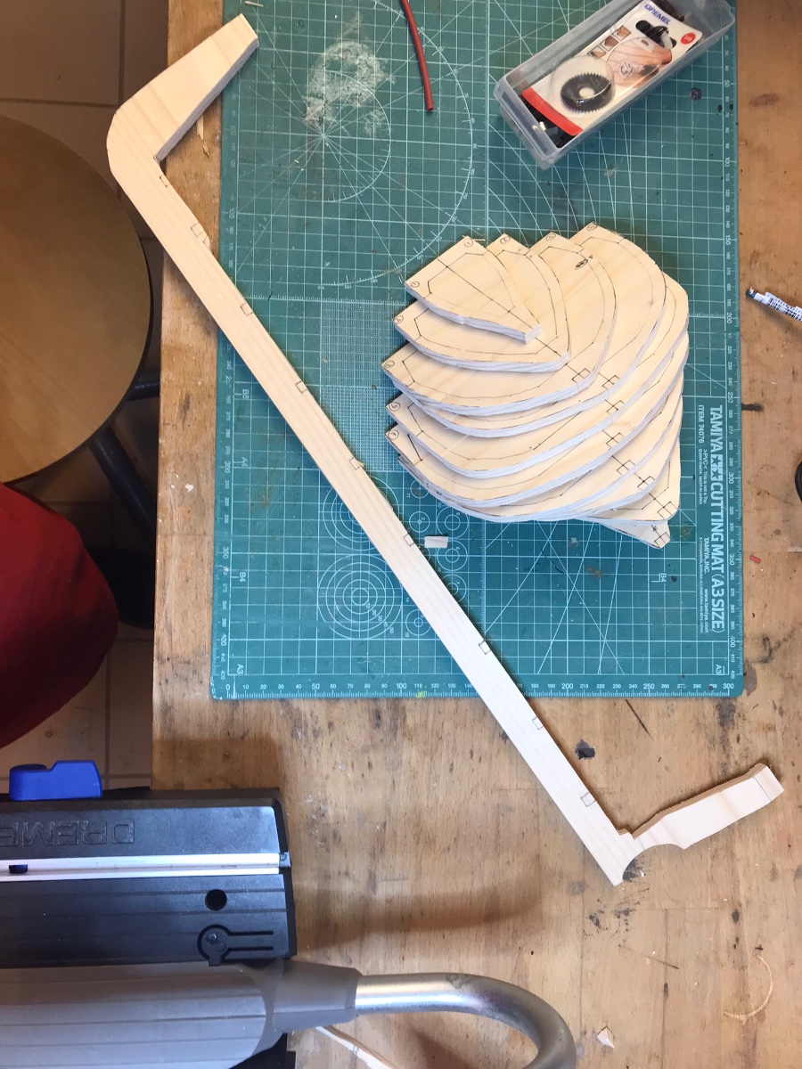
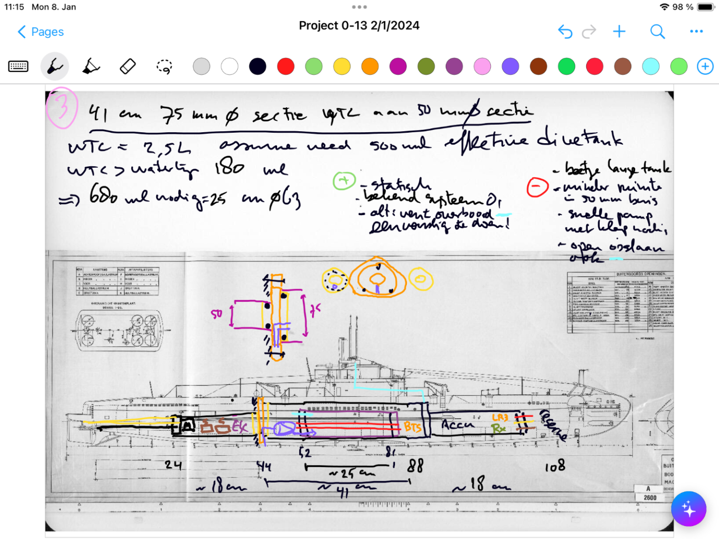
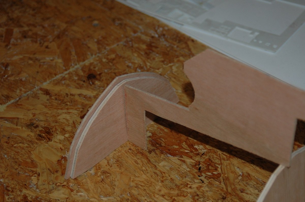
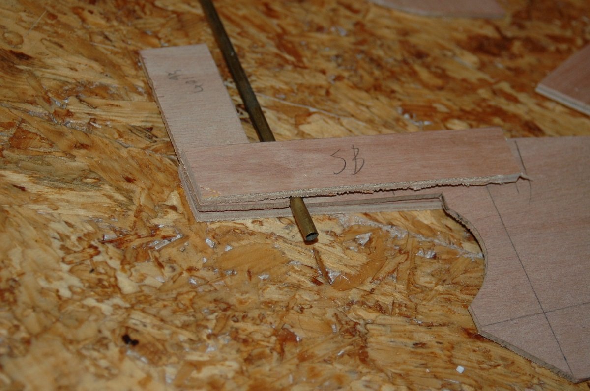
 I’m just starting this new project. Netherlands started WW2 with 23 submarines, split evenly between Netherlands-based and Dutch East Indies based. Seven of these subs were lost. O-13 first saw action in the Spanish civil war escorting ships, and then escaped from Netherlands to England in May 1040 with many other boats. However, already in June 1940 on her second war patrol in the waters between Norway and Denmark she failed to return. To this day the wreck has not been found, but every few years there are searches with newer equipment. The most likely cause of her loss is being struck by a mine in a (now known) minefield along her route, but also attacks by German aircraft and a collision with a Polish sub are remote possibilities. This model will be radio controlled, and the boat will be in-between my Holland-class O-1 (the first sub in the Dutch navy) and the larger K-XVIII which fought the Japanese in Asian waters. Both those models still sail regularly and well. O-13 was part of a class of 4, at 60 meters in length and with underwater displacement of 750 tons she was suitable for coastal waters, but also travelled to the Dutch islands in the Caribbean and the waters around Gibraltar. She had 4 torpedo tubes in the bow, one in the stern, and two 40mm guns retracting into buns. No deck gun was installed and some of the 40mm guns were removed as the class had significant stability issues. I have the original build plans (which can be downloaded freely from the Dutch national archives), but photos, especially dock-photos are relatively rare. I plan to build a traditional plank on frame wooden hull, impregnated with epoxy and coated with woven glass. Inside will be a watertight compartment made up of several connected tubes to house the technology to fill and empty the dive tank, and to control the two props, rudder and diveplanes. I hope to include running lights in the wet area and also attempt to functionalisme the folding forward dive planes visible in the picture. Due to space constraints I will not aim to make moving periscopes and functioning torpedo’s for this model. In the end the model will be 120cm long, 13cm wide at its widest point, likely weigh 3-5kg, and use tubing of 50 and 75 mm diameter as water tight compartment. So far, I’ve been doing rough planning of the location of components, closure means, and rough calculations of the required size of the dive tank to achieve a realistic waterline. I’ve also started to convert the build plans to individual frame drawings (taking into account the thickness of the hull planks (2mm) and the need to mount the frames on a build plank). Needless to say - this will not be a quick build!
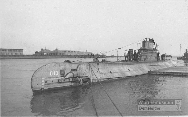
-
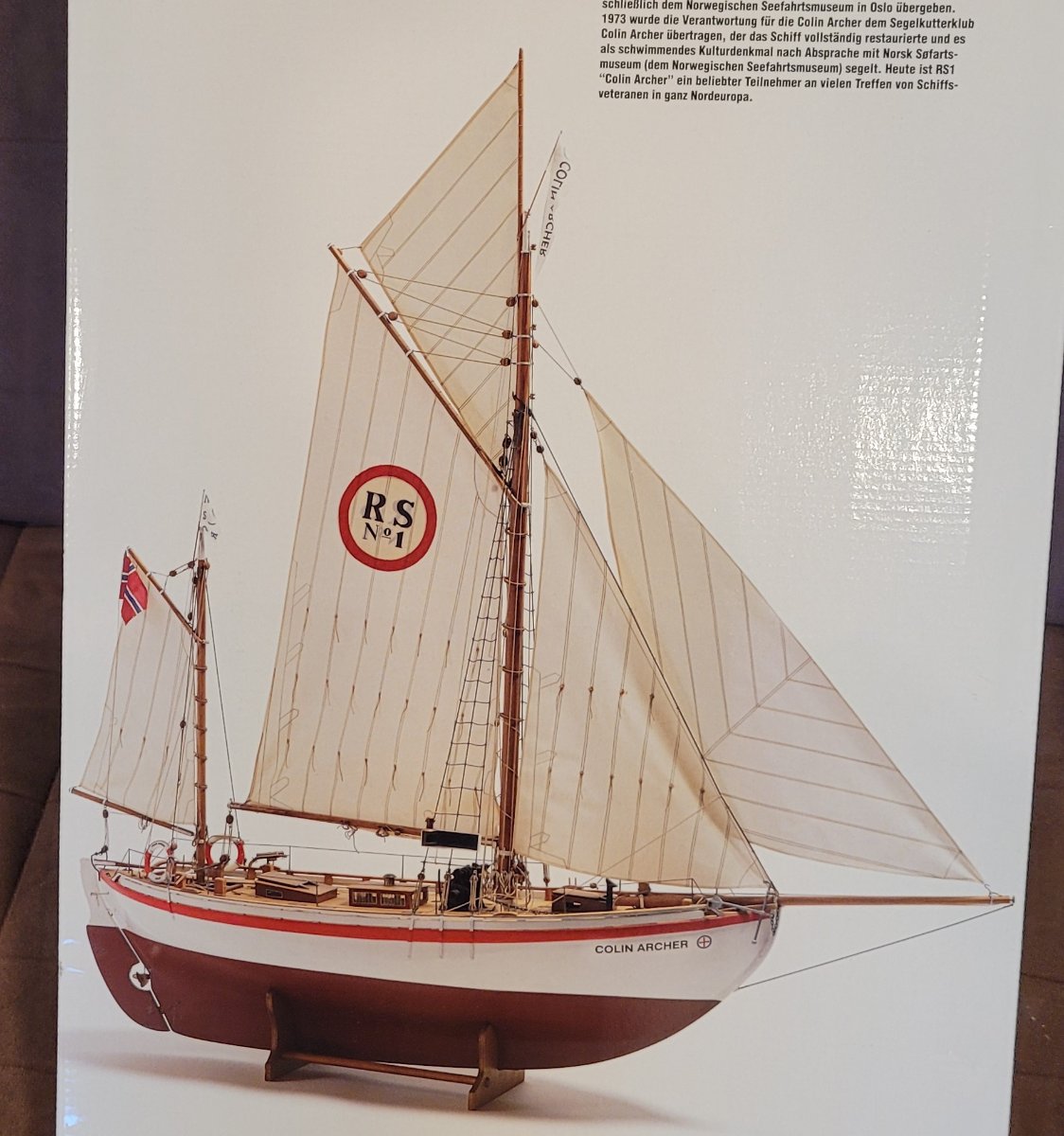
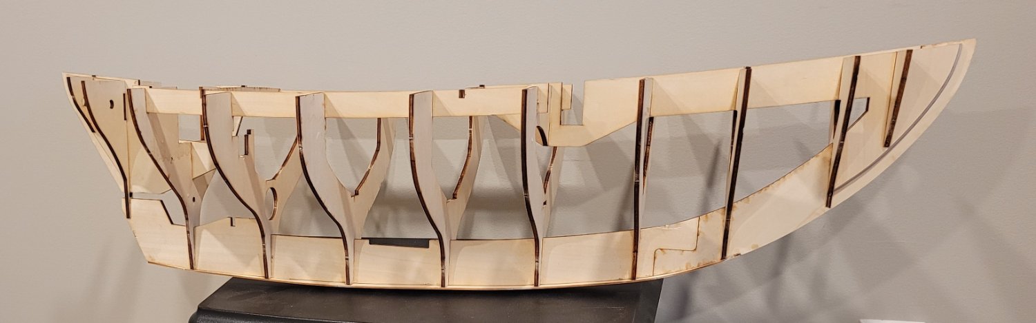
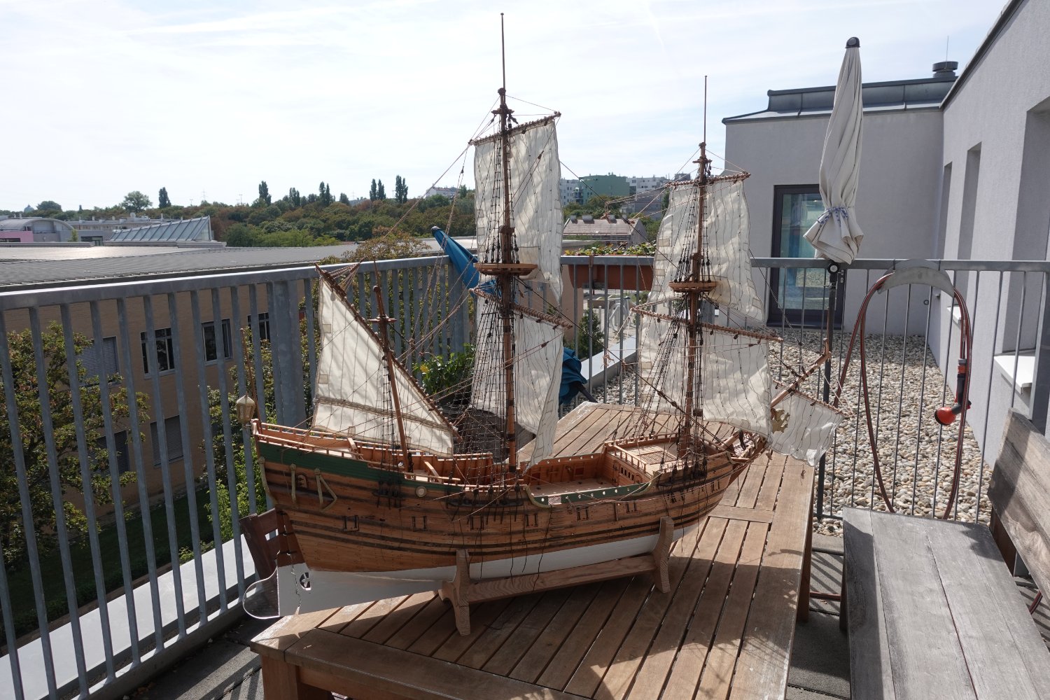
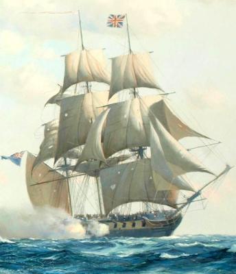
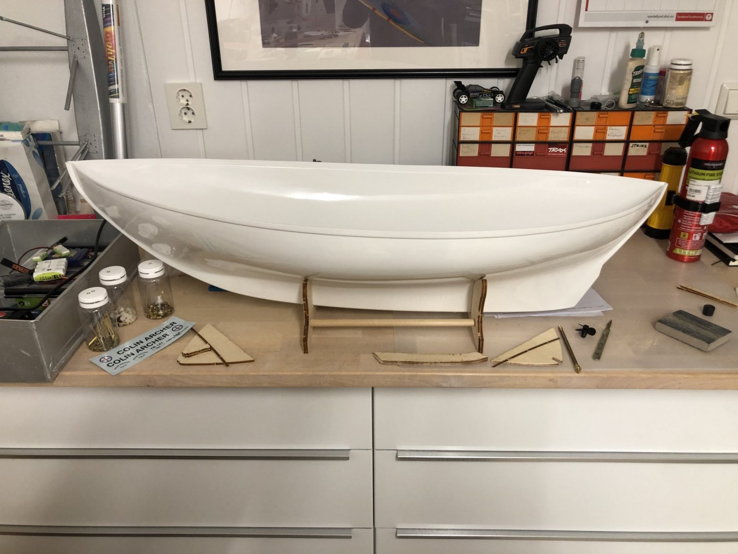
 RS1 Colin Archer, named for her designer / builder, was launched in 1893 in Larvik, Norway. The model, 1:15, is being kit built for Radio Control. The kit is by Billing Boats in Denmark. I wanted to build an RC boat and this one has a special appeal because Colin Archer also designed and built Leon, a 302 ton brigantine in 1880. I scratch built a model of Leon at 1:48. She now sits in a museum in Larvik dedicated to Colin Archer. Her build is described in forum "Build logs for subjects built 1851 - 1900". RS1 Colin Archer, after 40 years of very successful rescue operations saving many Norwegian fishermen, is now owned by the Norwegian Maritime Museum in Oslo. She is maintained and sailed at vintage ship gatherings in Northern Europe by the Colin Archer Cutter Club. The kit models her after the rescue years as she did not have an auxiliary engine until after she 'retired'. This picture is from the box top of the kit. On the way to being ready for planking, the hull is 37" long. Sparred she will be 50" long (62.5'), 54" high (67.5') with a 13" beam (16.25').

- 53 replies
-
- 3
-
-
- Colin Archer
- Radio
- (and 1 more)
-
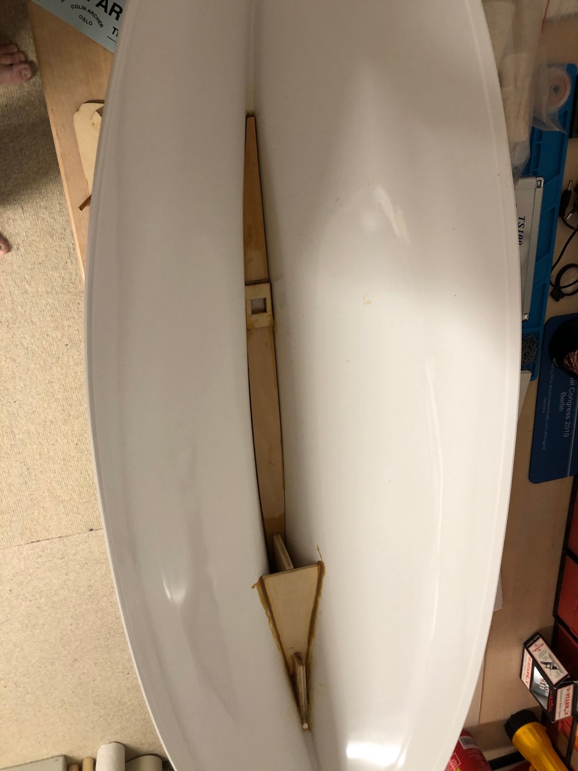
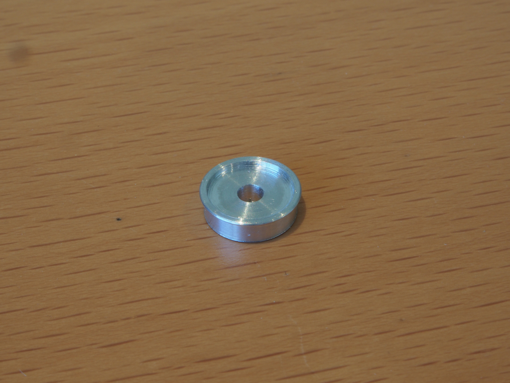
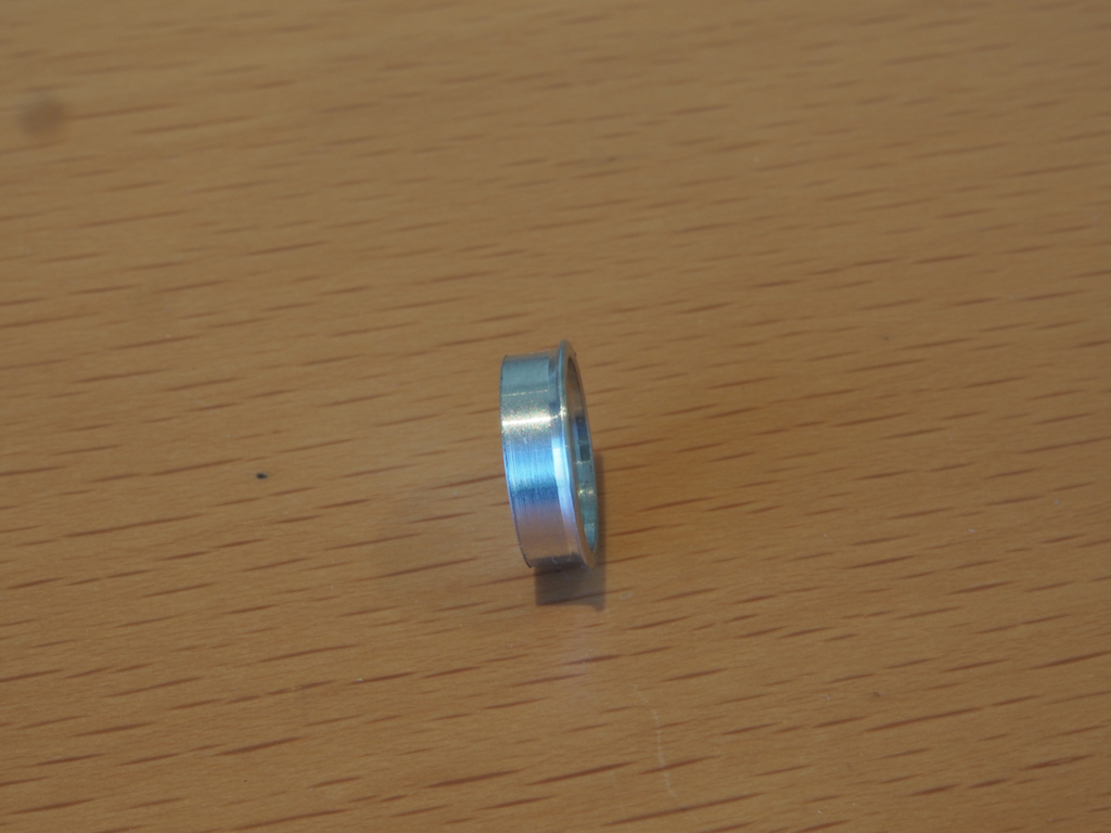
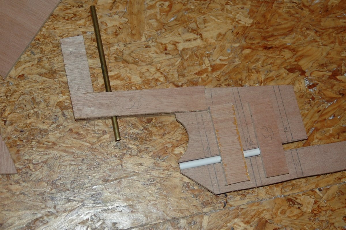
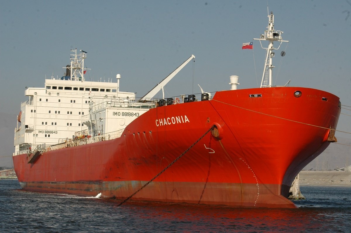
 Well a very old project of mine started back in 2010. It's been around ever since, working on it on and off until now. It's been bothering me ever since, she's the reason why I don't like to have a shelf of doom with long lasting projects. With every new small scale project I start, she's standing behind me, nagging for attention. As of late I've been busy planning to finally finish her and since the Spartacus project is on hold for the time being, I've slowly restarted construction on Chaconia. At first I built in a continuous period, however the pace slowed down during the detailing phase and eventually I've abandoned it. At first it would be temporary, just to take on a smaller project and finally get something finished, but as you can imagine, then came another "quick" project and another... Sometimes I did put her in the water and did some small jobs, but it never became my main project again. Now I'm intending to promote her again to the main project. So what is she? Chaconia is an LPG tanker, carrying Butane, Propane (or both) or Ammonia. Back in the days, she was mainly used to transport Ammonia from Trinidad (and other places) to the US (Gulf of Mexico area) for fertilizer production. She also brought Ammonia to Chile for production of explosives for the mining industry. She's not the cutest of ships, but back then it sounded like a good idea. In the end, so many years later, I must say that my period onboard that ship was probably, travelling wise, the most interesting voyage I ever did, covering a large part of South and Central America, including Maghellan Strait and Panama Canal passages. Since I didn't have a lot of resources back then, she was built in sub-optimal conditions and I also didn't have any expertise for such a project, having just started scratch-building in small scale ships. I shouldn't have done a project like that as a first large scale scratch build... In any case, she's there now, so I'll need to finish her. I'll bring you up to speed in probably quite a few posts with pictures. Basic construction was a wooden frame and hull, covered with glass fibre. From the start the R/C idea was incorporated and that complicated things. I had seen a lot of R/C projects online, but they were always twin screw warships. Having a straight, single-piece, keel, which wouldn't work for my project. So I had to get a solution. It's also my first- and only- planking job till now. The rudder post in position. Rudder post and propellor shaft spaces created.
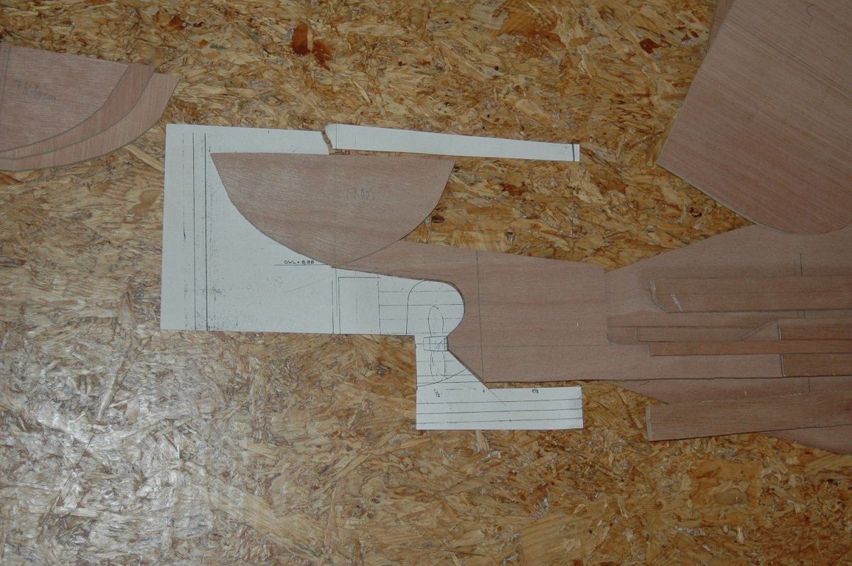
-
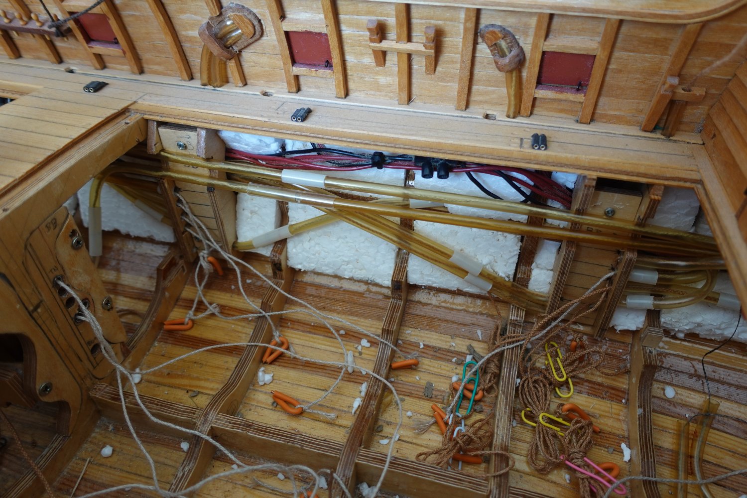
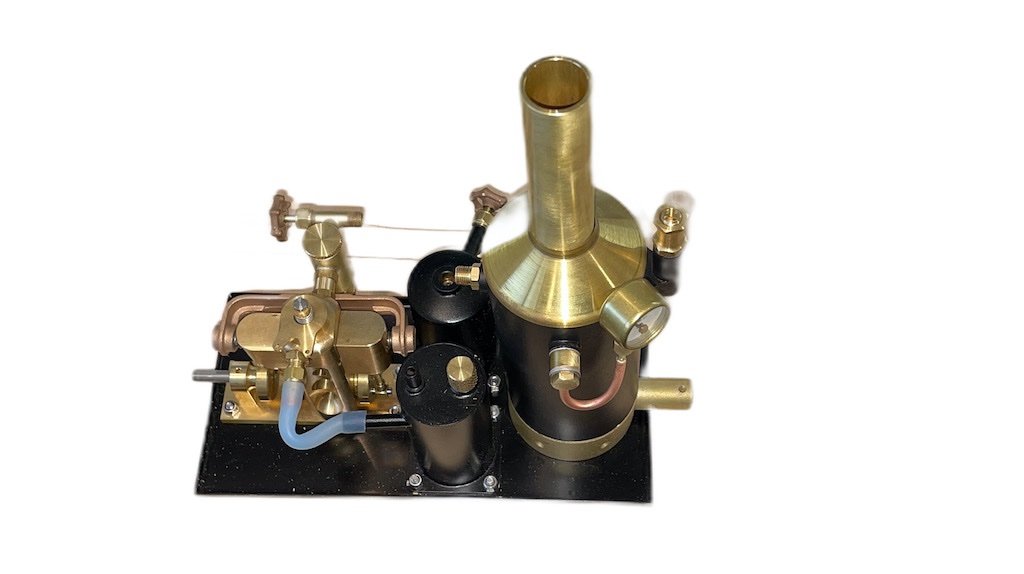
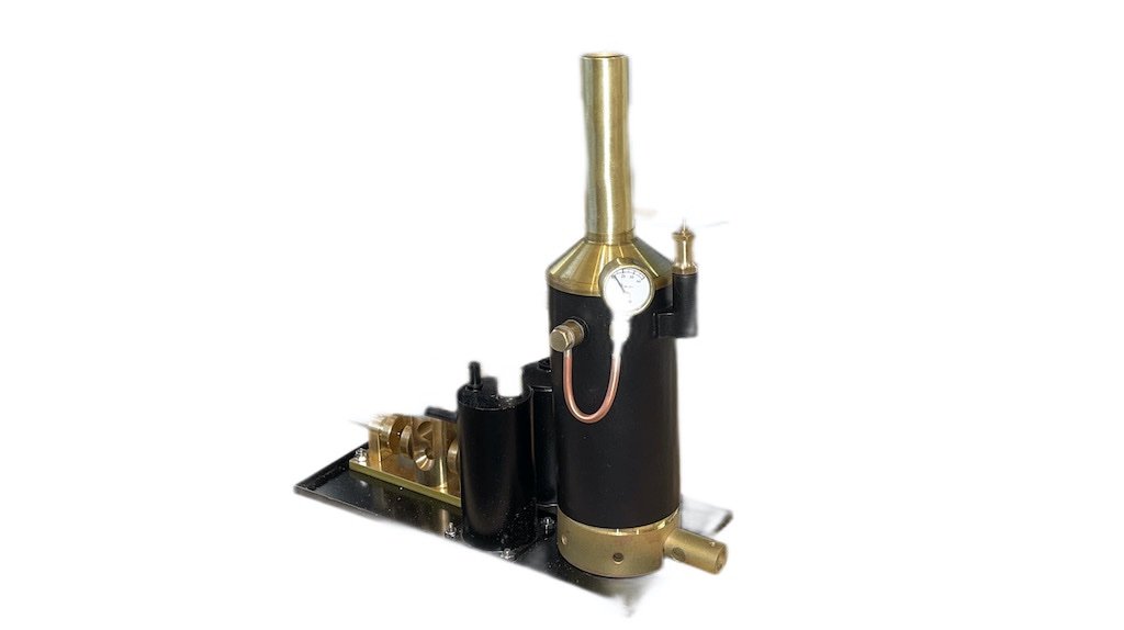
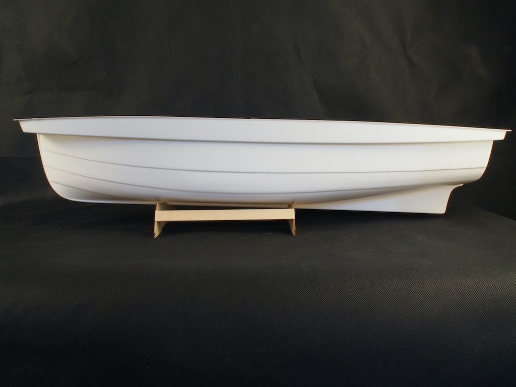
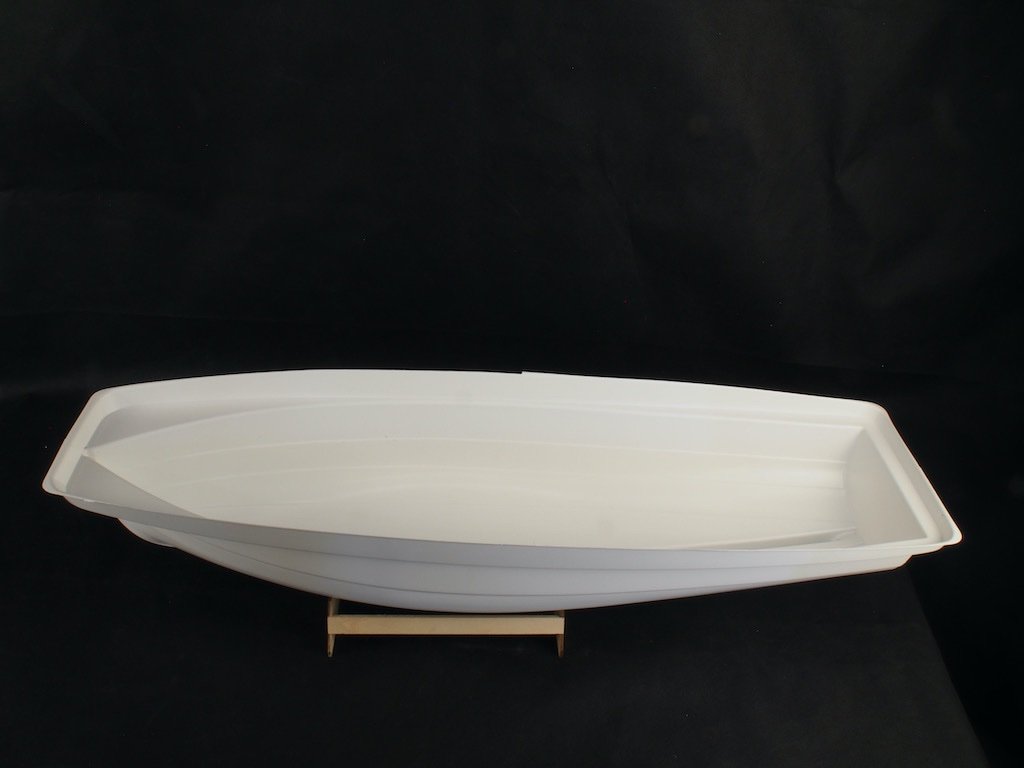
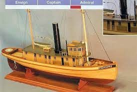
 Introduction I have long had a hankering to build a small launch with live steam propulsion. The African Queen seemed to be an ideal choice of subject, however finding a kit to modify proved somewhat elusive. In the end, I settled on the Billings offering in 1:12 scale as it claims to be suitable for Radio Control (albeit using an electric motor). Here is a picture of the box art. The next challenge was finding a steam plant suitable for inclusion in the model. After an exhaustive search, I settled on a complete steam plant from Miniature Steam Models (MSM) in Melbourne, Australia. It is a 2” boiler with the “Avon” twin cylinder double acting oscillating steam engine. The steam plant comes complete with a boiler certificate and the engine is matched to the size of the boiler. For the tech heads, it has an 8mm bore and an 11mm stroke (and it is reversing). Overall, it is very similar in size to the “fake” boiler/engine plant provided in the Billings kit. Here are a couple of pictures of the steam plant as provided from MSM. What’s in the box? The Billings kit is fairly typical of the Billings offerings. The hull is provided as a single-piece vacuum formed ABS mould. The rest of the kit includes a variety of laser cut plywood parts, some strip wood (not particularly high quality), some brass components and some plastic components. As I will not be using the provided boiler/engine parts, a lot of these will be redundant. I was concerned by the apparent flimsiness of the hull, and my plan is to sheath the hull in timber, and then fibreglass over the top of that. To this end, I have obtained some 1mm thick Alaskan Yellow Cedar from Hobby Mill EU to be cut into planks as appropriate. I will also be adding some aftermarket timber for the deck planking, as the kit would have you simple draw planking lines onto the provided plywood. I’m currently in the process of placing an order for this with Hobby Mill EU. Instructions are, I believe, typical of Billings – which is to say, next to useless. This is not a kit for a beginner, although it is marketed as “Advanced Beginner”. We shall have to see whether I have sufficient skills to pull this off – otherwise, there is considerable investment “down the tube”. The Hull Here are a couple of pictures of the ABS hull. As can be seen in the pictures, there is a considerable excess lip around the upper edge. I will need to remove the vertical component of this before I can do anything else. My current plan is to do that, and then fit the internal frames to provide some stiffening before attempting the outer planking. Welcome aboard for what might prove to be an "interesting" journey!
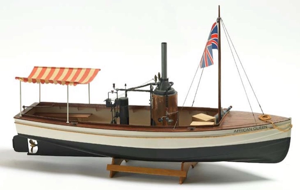
- 37 replies
-
- 18
-
-
- live steam
- radio
- (and 2 more)
-
 Hello everyone: This log will go back in time a bit, like a lot of my projects this one started roughly twenty years ago. During the early 2000's this tug, the Malaspina Straits, was listed for sale on a used vessel website. With the posting were a few photos of the tug out of the water along with a few drawings. At the time I was quite into 3D modelling and thought that this would be a fun project to make a few renderings of. One thing led to another and the project never did get off of the ground and the files were tucked away. Fast forward to sometime around 2017 and it was suggested that we build a pond at the local museum; the model ship bug bit, at this same time I was realizing that HO scale model trains, while neat, just won't fit my current living arrangements. The ship bug really bit when the missus and I purchased a property with a small pond, and a pond needs a boat so the search was on for a prototype. While organizing some files I stumbled upon the old drawings and photos saved some twenty years prior. A little looking online showed that she was again for sale and a few queries put me onto the naval architect. After making a call to see about getting a set of drawings the architect noted that this was a common request and asked that I mail a cheque to them, but make it out to another independent society that is rebuilding a steam tug, the SS Master. The Master is British Columbia's last surviving wooden hulled steam tug, once I learned that the "fee" for the drawings was going to help with this restoration I couldn't get the cheque book fast enough. Check out the SS Master here: SS Master The Malaspina Straits was launched in 1964 and was one of a group of three ships, the Rasario Straits and the third escapes me at the moment, all built for Straits Towing Ltd. of Vancouver, BC. Considered a hot rod of a tug it was primarily designed for moving chip barges up and down the West Coast of British Columbia. The tug moved around to various owners over the years and was refit a few times, the model that I am building will be per the original drawings. I've never seen the tug myself so can't post any photos of it but here is a link to a page with a bit more detail: Malaspina Straits - Nauticapedia.ca As far as model ships go, I've never built one, at least from scratch however I have turned heaps of styrene into other buildings, trucks and various model railway related things. As I was more familiar with modelling in styrene and as this model will be used in the water styrene felt like a better fit than wood, it may be, it may not be, time will tell. Just after the ugliness of Covid descended upon the world the model got under way, a few 4' by 8' sheets of styrene were purchased from a local supplier and bits started to be cut out...
- 7 replies
-
- 4
-
-
- Malaspina Straits
- plastic
- (and 1 more)
-
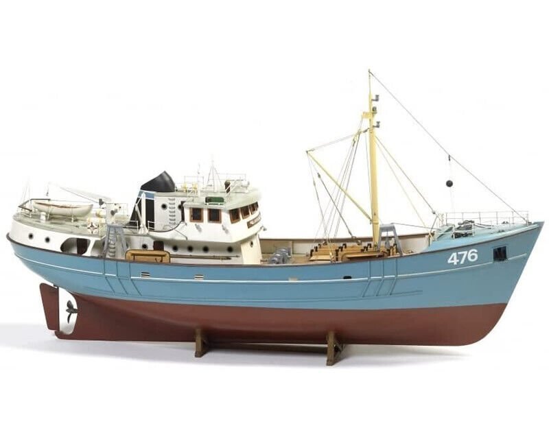
 As I near the completion of Barque Stefano, I had a hankering to build something that was simple, where I could just follow the instructions, straight out of the box. Time will tell how closely I manage to do that, but having looked longingly at Nordkap as a teenager, she was the vessel I settled upon. Here's a picture of what she's meant to end up looking like Nordkap builds up into an 81cm l.o.a, 21cm beam vessel - so there'll be loads of room in the hull for all the radio gubbins. She's also small enough not to be too cumbersome to move around when building. I bought a new building board, and set about separating the laser cut frames from the "sprues". Then I looked at the plans and noticed some strange discrepancies... There are two sets of measurements on plan 1 - the first shows the gaps between the forward extents of the frames (4-7) - this should measure up to 159mm. A second set of measurements show the filler blocks that will sit on top of the keel - these are 48mm, 50mm and 50mm - 148mm, leaving only 11mm for three frames - but the frames are 4mm at the least - closer to 5mm in fact... The instructions simply say that the frames are "quite vertical" and then leave the builder to work it out. Instead of guessing, I decided that using the deck would be a neat way of ensuring that the frames were essentially in the right position, so this part was cut out as well and used as a guide to get the frames in the right place. So... so far I've fitted the frames, and added the blocks in between - which have all turned out to be around the 48mm mark. This _may_ come back and bite me later, but I feel much more confident knowing that the deck fits with the frames in their locations, than simply hoping for the best. The observant among you may notice a curvature of the keel (higher in the middle than at bow and stern - it's around 4mm, although it looks worse, perhaps because of lens distortion in this photo) - ironically, having cut the keel parts to be 55cm and 52cm respectively, I now realise that these are perhaps slightly short for the deck... removing the deck after gluing the frames in place got rid of this curvature entirely, and so I probably will need to modify the deck a little down the line, but that's fine - it'll be millimetres here and there, not centimetres, and the hull will be the right shape. The next step is to add the stringers along the bulkhead tops, and as I do that I can ensure the keel is straight. I'm not worried about modifying the deck to fit, I just wanted everything to be in the right ballpark. I've also added the doublers that create something of a rabbet at bow and stern. More soon Rob
- 56 replies
-
- 7
-
-
- Nordkap
- Billing Boats
- (and 1 more)
-
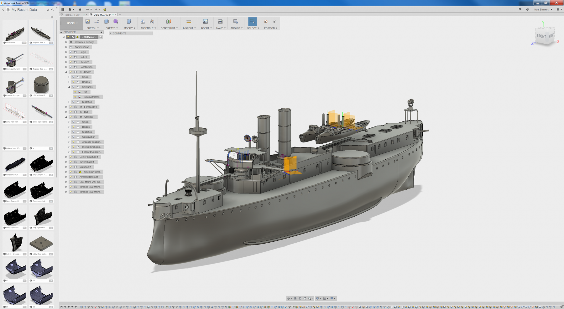
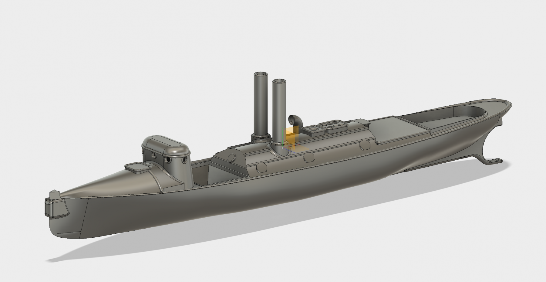
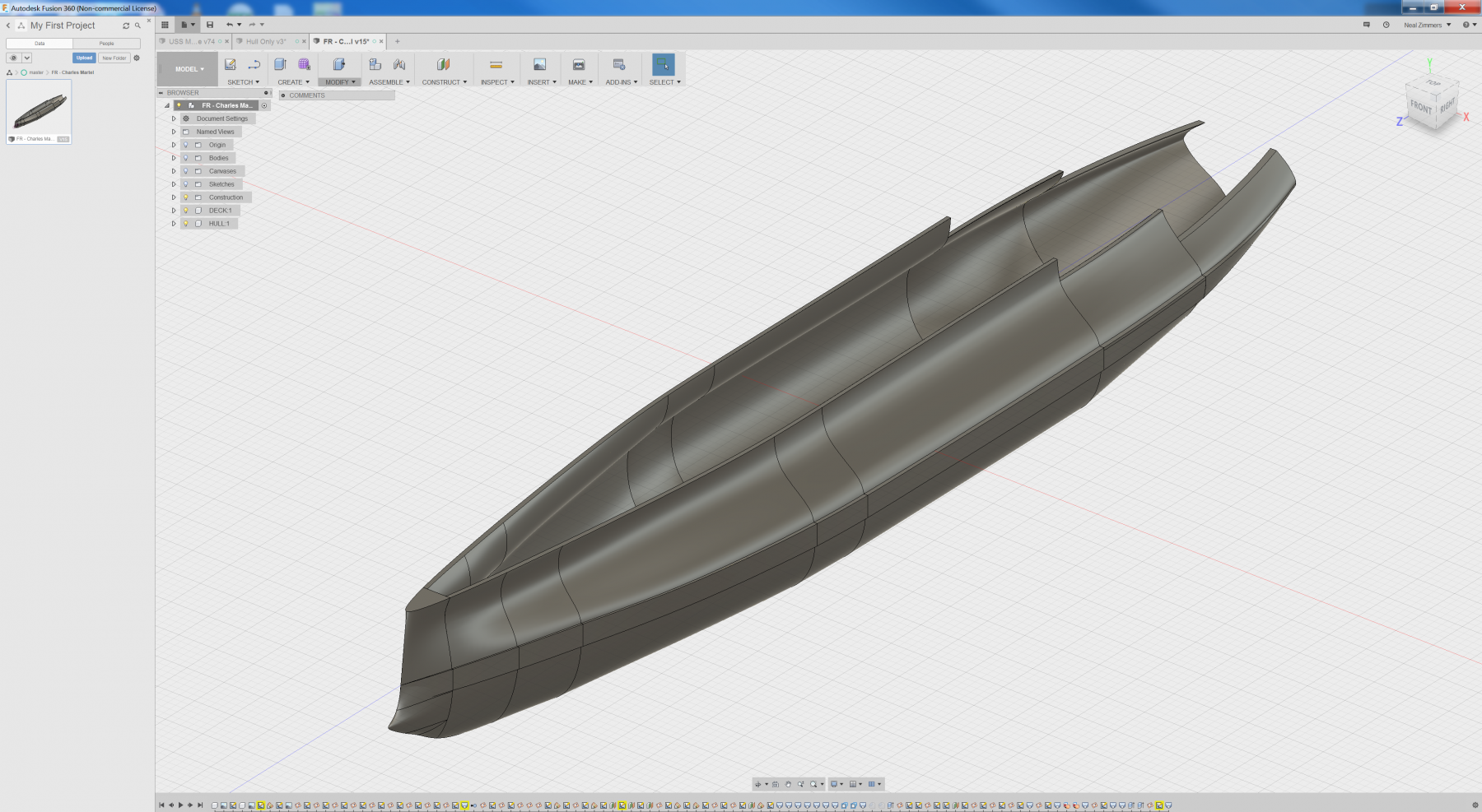
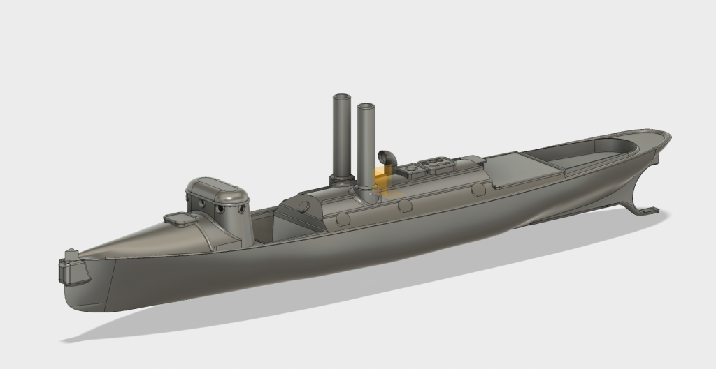
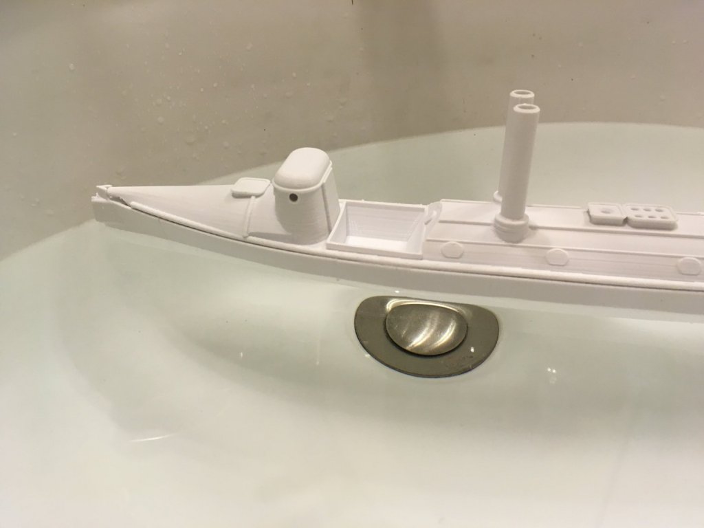
 Hello all, I’d like to share a project I’ve been working on for the past month. I chose to start with the USS Maine in 1/72 scale but in truth I’m captivated by just about any pre-dreadnaught design especially some of the tumblehome hulls like the USS Brooklyn and the French Massena, Carnot, etc. Most of the work accomplished thus far has been in the cad program (fusion 360) but I’m just about to start printing parts as I move through and complete the design. I am including the torpedo boats that were meant for the Maine, and hope to eventually figure out a way to launch them while underway.
-
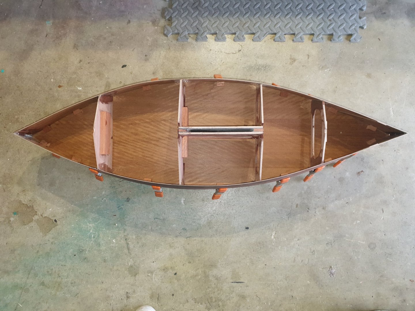
 If you woukd like to see Emma sailing then go on to you tube and Type in " Emma, rc sailing sloop by Gary Webb". Gary has quite a few vids out there now on how to do this and that with boats he has dedigned. Gary is a full scale boat builder and exceptional modeller. He models to very clear cut clean lines with practicalities coming foremost. I ordered up the plans from USA electronically so received them pdf and had them printed out to the correct size. Emma is a very simple hard chine boat and made from door skins as opposed to the really expensive 3mm birch ply from the model shops. So she is rugged but cheap to build. I cut out the four bulkhead patterns from the plan. I leave around 6mm on the perifery ( sorry my false teeth fell out saying that so I ended up spelling it wrongly). Then glued onto the ply and fretted out with my electric fret saw. The crotch of this hull is to build the fin box first and then glue it to the centre two bulkheads. The sides if the fin box were first treated with fibre glass matting for water proofing and strength. The centre two bulkheads were then glued on to it. The crotch was first C A glued to hold it together and then a fillet of 5 minute epoxy applied on every joint. Strong as an ox!. The sides of the hull had three small holes drilled biw and stern to enable the two sides to be stitched together with copper wire from an earth cable. After stitching, the sides were held apart and the crotch unit CA d in its marked position. It was then epoxy filleted at all joints. Finally the two other bulkheads were fitted in thr same fashion. The hull bottoms were then cut out and glued on using the same procedure.

-
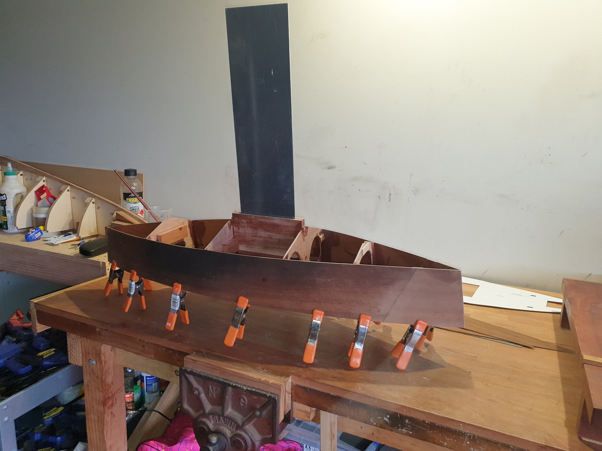
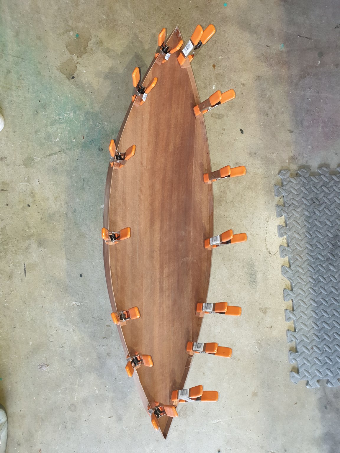
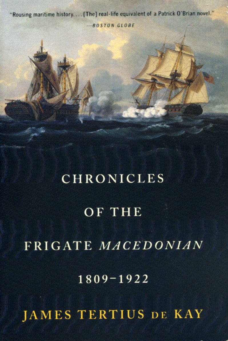
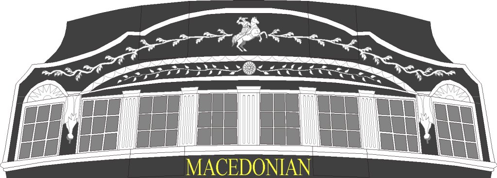
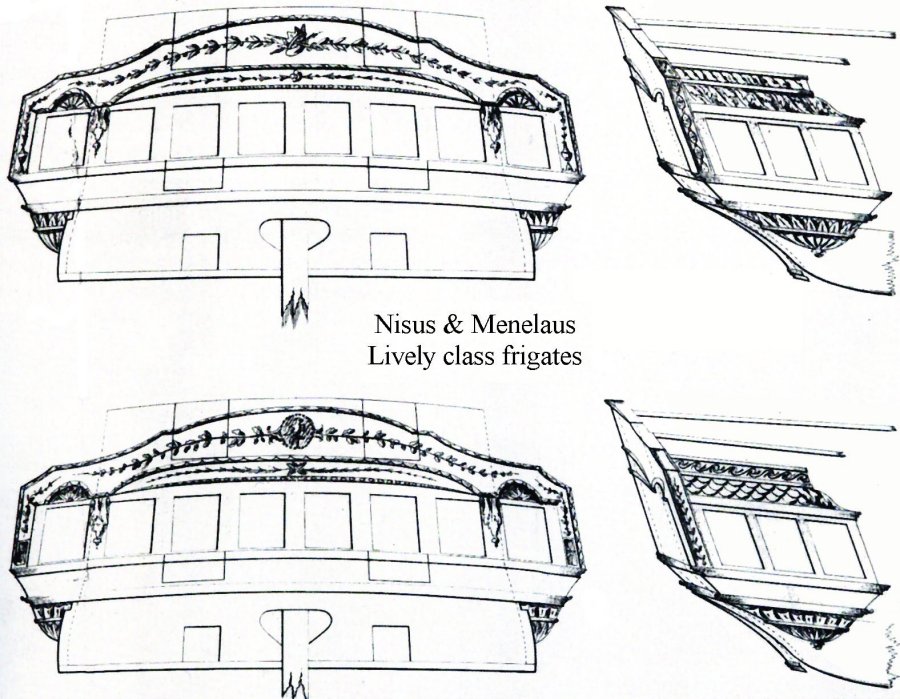
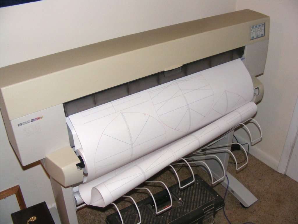
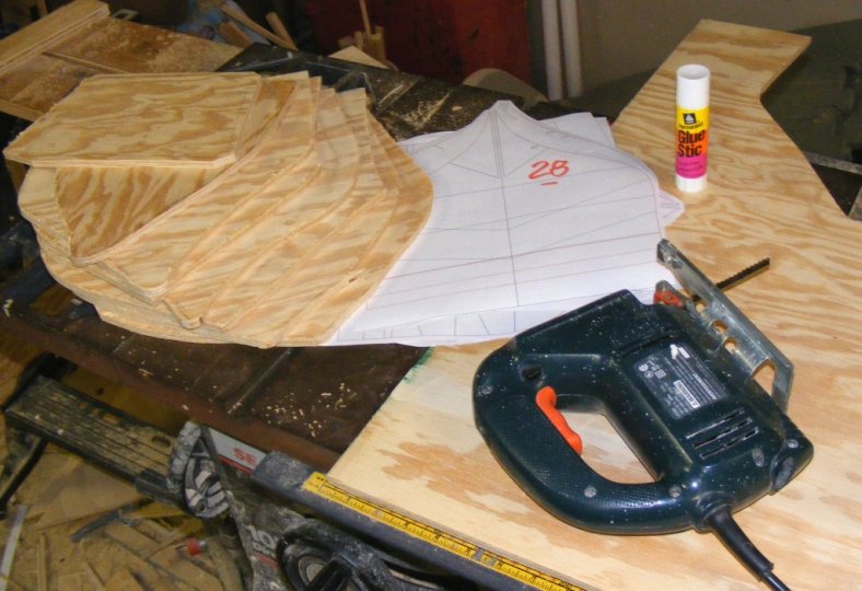
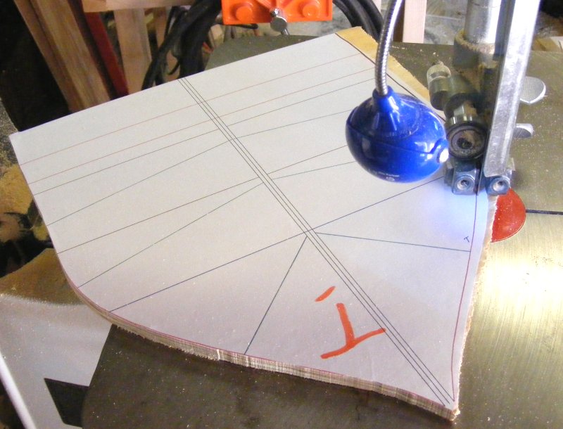
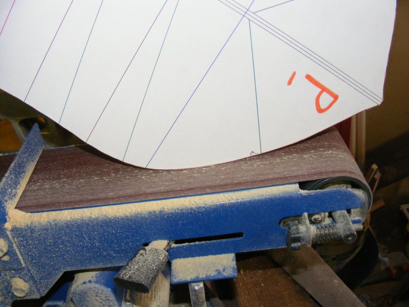
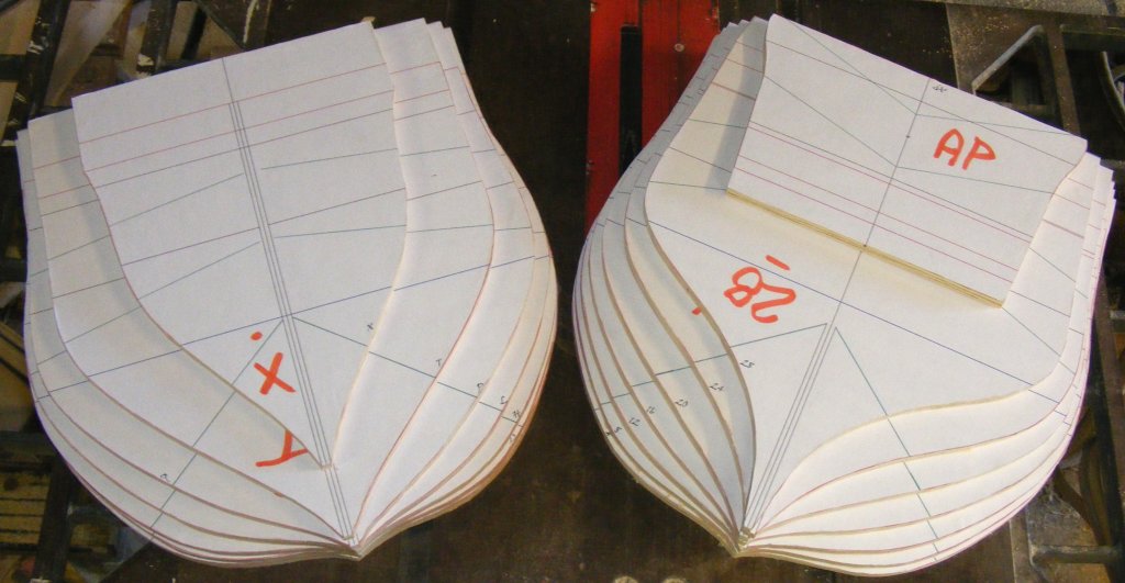
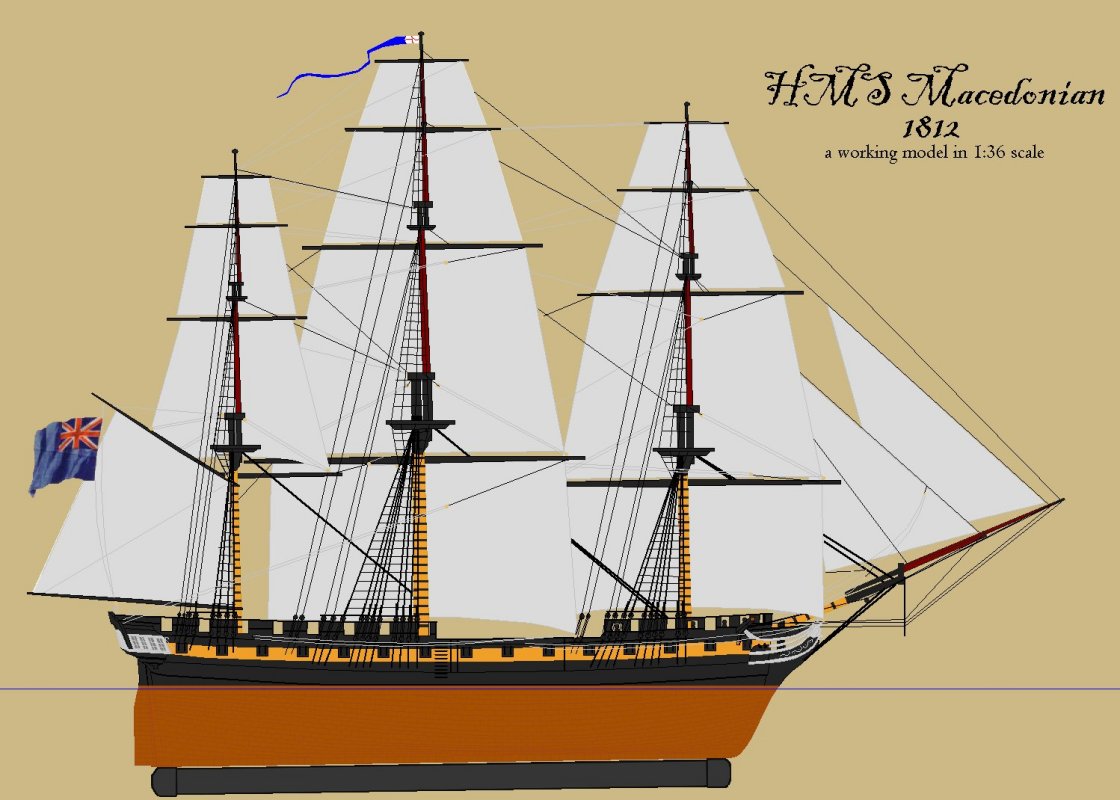
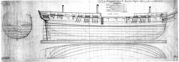
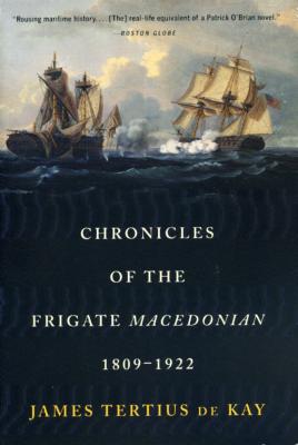
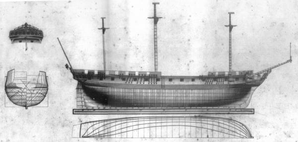
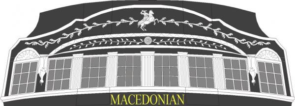
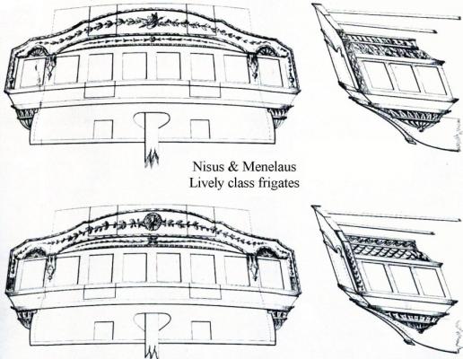
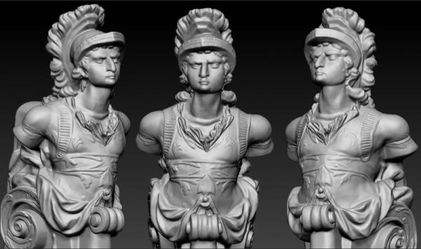
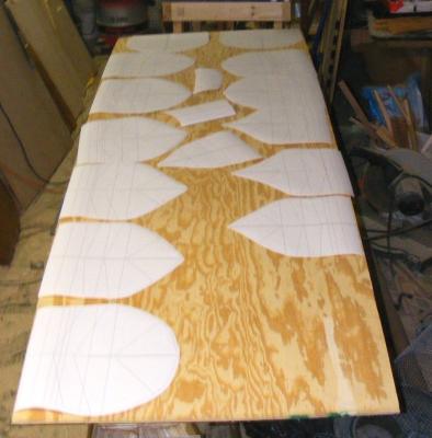
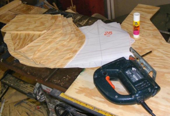
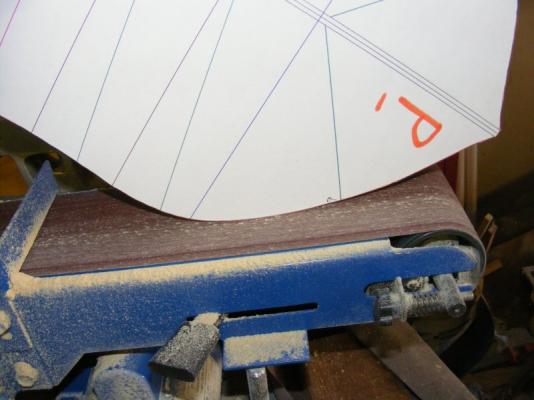
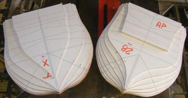
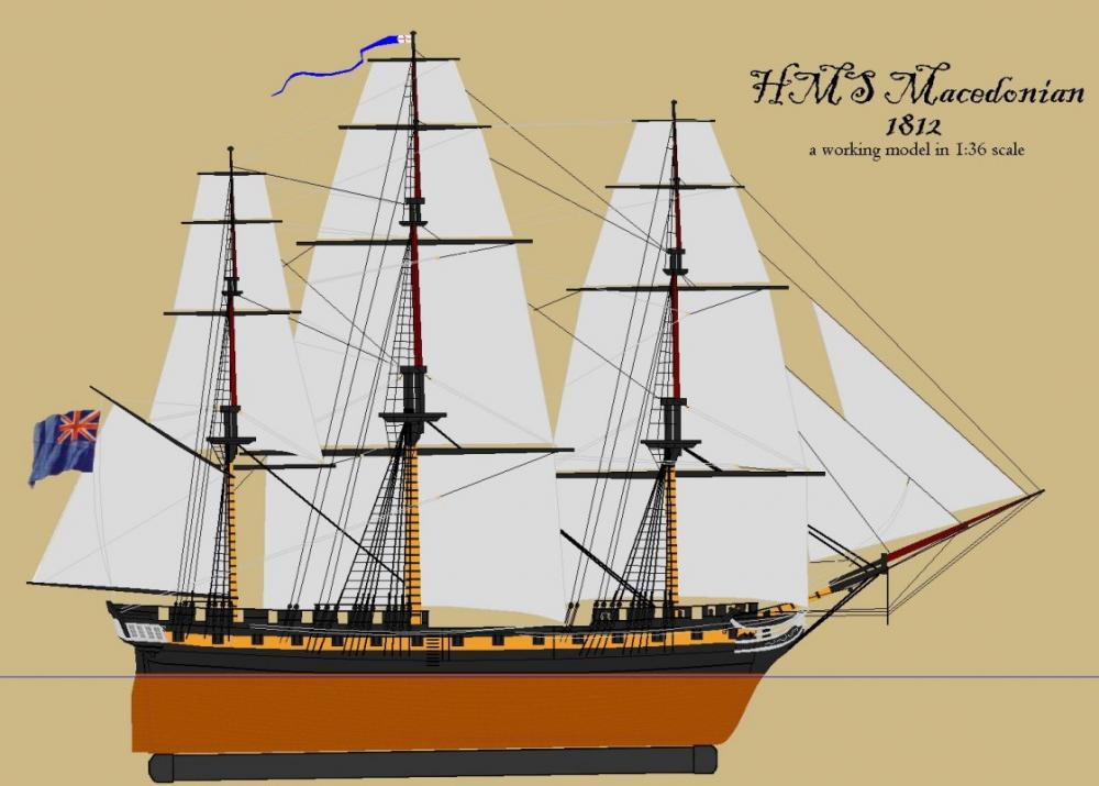
I first set foot on board the Constitution when I was 7 years old, and I was hooked on sailing ships ever since. My elementary school library had C S Forester's The Captain From Connecticut which I loved and led me to Forester's other work, namely Hornblower. In fact, the 16 foot daysailer I've had since 1979 is named Lydia. I spent my teens and twenties working under sail and power, from barkentines to tugs. I've built several of the 1:96 scale Constitution/United States Revell kits, two of them were RCed; but I always wanted a sailing model of the ubiquitous British frigate, and no one made that kit. I finally decided to build one. Already deep into building an 1850's American sloop-of-war, and with a Baltimore Clipper schooner already planked up, I began a third model of the HMS Macedonian. I chose Macedonian because I could easily get Chapelle's drawing of her from The American Sailing Navy from the Smithsonian, and she was interesting. Macedonian by Gardner Macedonian was a Lively class frigate rated at 38 guns, another of Sir William Rule's designs. Launched in 1810, during the War of 1812 she had the misfortune to meet the American frigate United States, a Constitution class 44 and was captured. She was taken into the American Navy and served until 1828 when she was broken up and replaced by a new ship. Lively Bacchante The story of Macedonian is well told in Chronicles of the Frigate Macedonian, 1809-1922 by James T deKay and I've posted a fair history of the ship on my page There's lots of data available on how the British built and out-fitted their frigates, and even Macedonian's figurehead still exists, but I never have found any reliable information on what her stern looked like. What I've come up with is my own conjecture based on the sterns of other Lively class frigates. The mounted figure is from a statue of Alexander that existed when Macedonian was built. The round object is the "Vergina Sun" found at ancient Macedonian sites and dating from the time of Alexander's father. Symbology available when Macedonian was built and while this is my own guess, it's at least a logical guess. I considered using Alexander's profile from a coin in place of the mounted figure, but his face is already on the bow - given the choice, I'd think an English builder would choose the horse. When the drawings came in from the Smithsonian, the first thing I did was have them digitally scanned. I then rescaled them from 1:48 up to 1:36 mostly so this model would be the same scale as my Constellation. That done, I made up a sheet with each station drawn full-sized, and printed that on my plotter. At this scale, the model should be; Length: 59" taffrail to Alexander's nose Beam molded: 13.3" Draught: 6.87" without the removable ballast keel Her length over the rig will be about 7' and she will stand from keel to truck, about 4'. (I'll update this with more accurate numbers and metric equivalents at a later date) These paper patterns were used to rough cut the wooden stations from 3/8" plywood. Each paper pattern was then glued onto it's station close cut on the bandsaw, and then fined up on the beltsander where some bevel was put into the forward and after stations.


- 81 replies
-
- 12
-
-
- macedonian
- frigate
- (and 3 more)
-
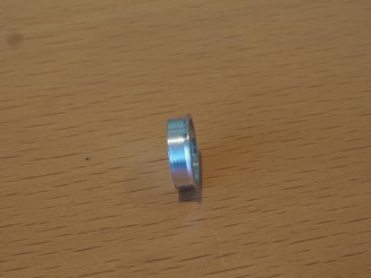
.thumb.jpeg.ee4d205046163acd786c8b7e92026d43.jpeg) Started building a old Billing Boats kit. PS hull was told to be the last kit, they started a new production in wood some years later, available today. some tip about glue will be asked for 🙂
Started building a old Billing Boats kit. PS hull was told to be the last kit, they started a new production in wood some years later, available today. some tip about glue will be asked for 🙂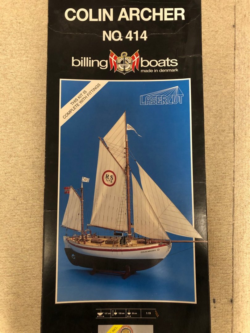

- 89 replies
-
- 4
-
-
- billing boats
- colin archer
- (and 1 more)
-
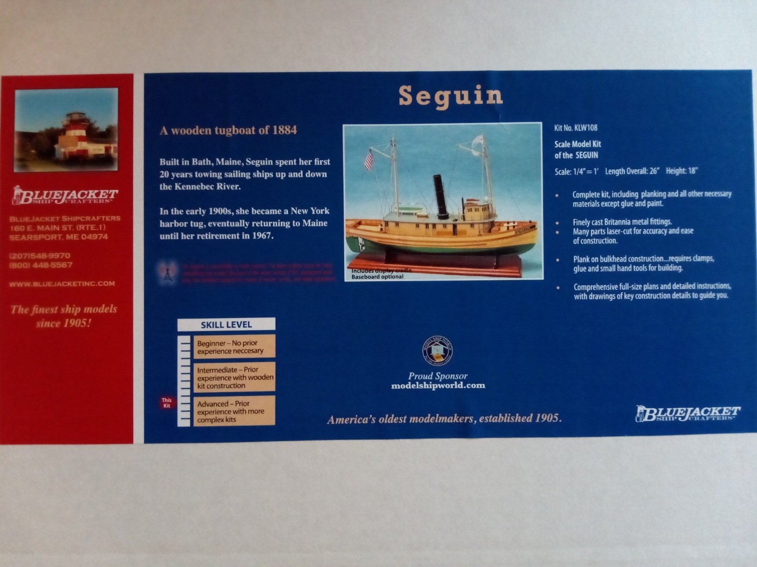
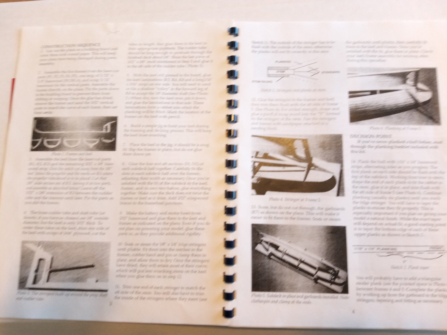
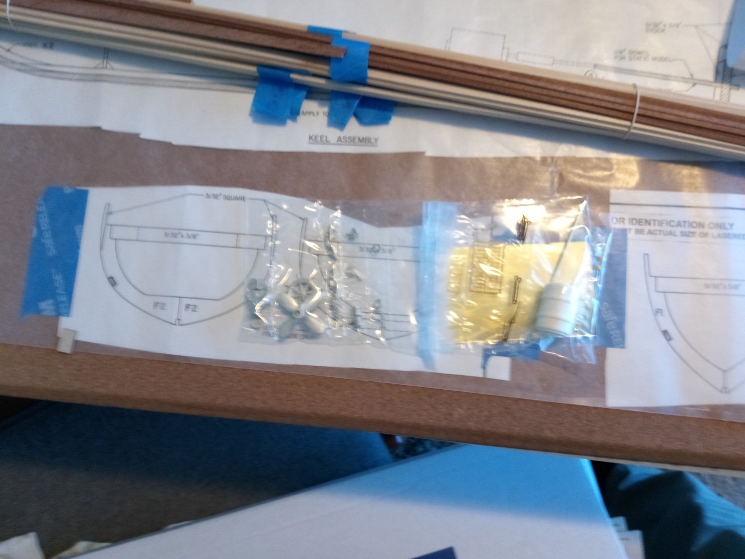
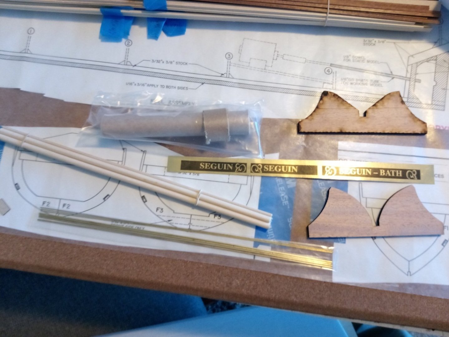
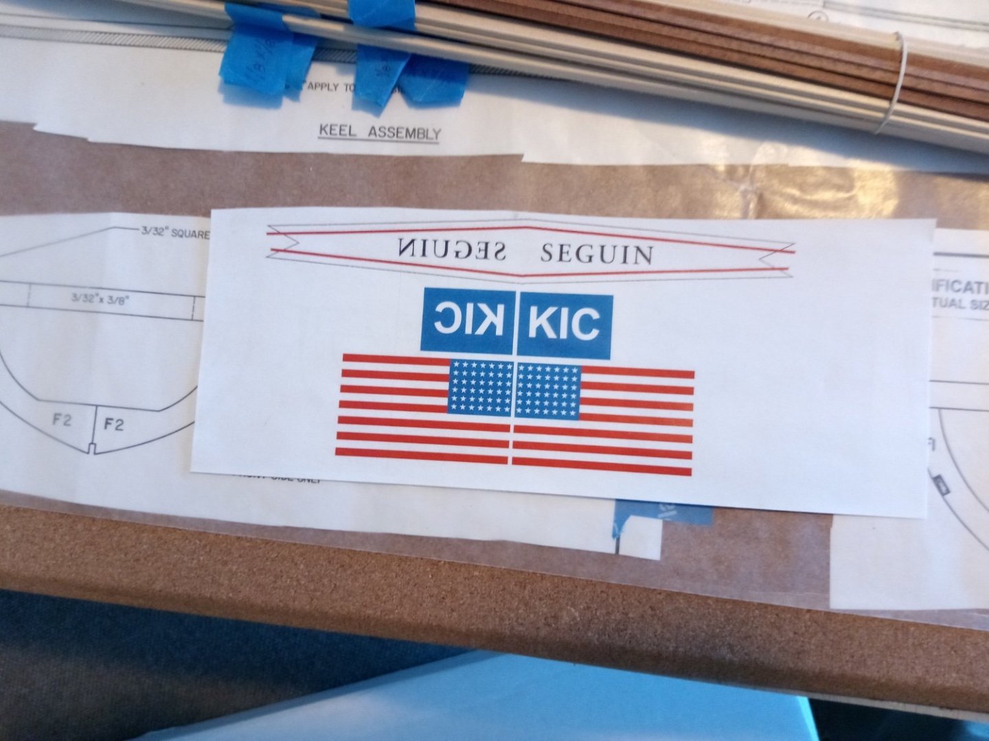
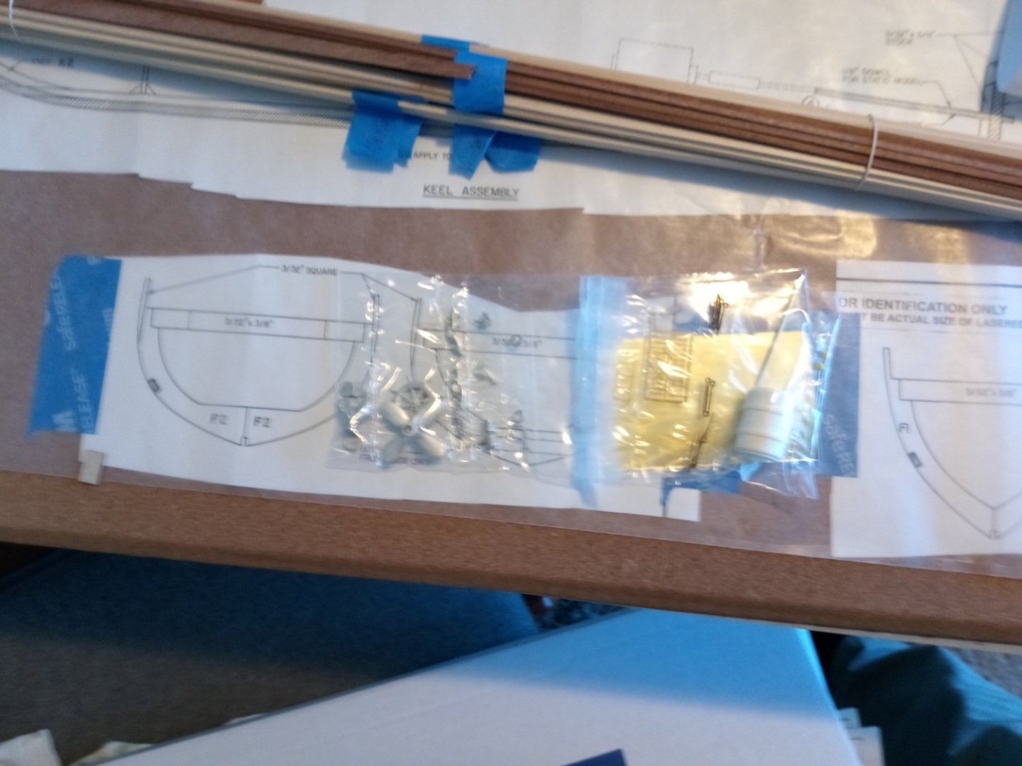
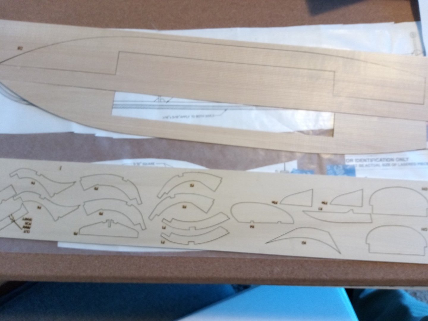
 The Seguin From the BlueJacket website: “Historic wooden tugboat, 1884. Built in Bath, ME, the Seguin spent her first years towing wooden sailing vessels in the Kennebec River and towing cargo barges along the Atlantic coast. In the early 1900’s, she became a New York harbor tug, finally returning to an active career in Maine until retiring in 1967”. Why I picked this kit I’ve wanted to try my hand at a Radio-Controlled kit, and while there are far easier kits on the market for a RC first - timer I was really attracted by how good this boat looks, so that even if the RC side is a bust, it should still look nice on the shelf. Since this boat will be waterborne it will be a challenge to get her watertight so I will be leaping into fiberglass, or at least resin - I will have to decide that after the hull is planked. RC I will try to remember to put a green “RC” (like at the start of this paragraph) at the beginning of any paragraph dealing with RC or waterproofing related so that those not interested in those parts can eye-scroll past them. References: Build logs, websites and online forums Building the George W. Washburn: regroups.com>forums>boats>scale boats>building the George W. Washburn a decent build log of a Dumas POF steam tug similar to SEGUIN, has some decent waterproofing and RC info RC Deans marine.co.uk RC and waterproofing info scattered about RC Ship modelers.com>technical library RC info RC MSW build logs (not the SEGUIN) that have decent RC and/or fiberglassing info a. gjdale’s 1949 Chris Craft b.mtdoramike’s 1954 Chris Craft Build logs for the BlueJacket kit a. RC rcgroups.com>Seguin by ropanach b. Model Ship World, Seguin 1884 by RVCHIMA great log of a gorgeous build of this kit, if mine turns out half as good as his I will be happy c. shipsofscale.com >forums (note: anyone can view the site but the photos are thumbnails, if you register on the site you can click on them and blow them up to usable size) both of the logs below are useful for pointing out some problems to avoid 1) Seguin by anchorman 2) Bluejacket Seguin by pathfinder69 RC There is a ton of websites you can find by googling “rc boats” or “fiberglassing rc boats” of varied quality and usefulness but worth some time to look around and bookmark the ones you like. Books: RC in Model Boats by John Cundell. Has a photo of the Seguin on the cover (might be the old Laughing Whale kit) Decent book found on Amazon for about $8. About half the book is dedicated to less relevant things like the history of the hobby, how RC clubs work, high speed RC racing boats, etc but it helped give me a better understanding of what to think about when installing RC equipment What’s in the Box? The kit provides 2 large, clear sheets of plans and an instruction book There is an assortment of dowels, strip wood and name board stickers A set of paper flags A bag of Britannia metal fittings, some sheet brass and a little photo-etch brass There is a fair amount of laser-cut wood of various thicknesses and pre-scribed deck planking material There is also some very detailed laser cut wood of 2 different types of wood that give the deckhouse its unique look. Next post I will show the RC equipment I ordered for this build
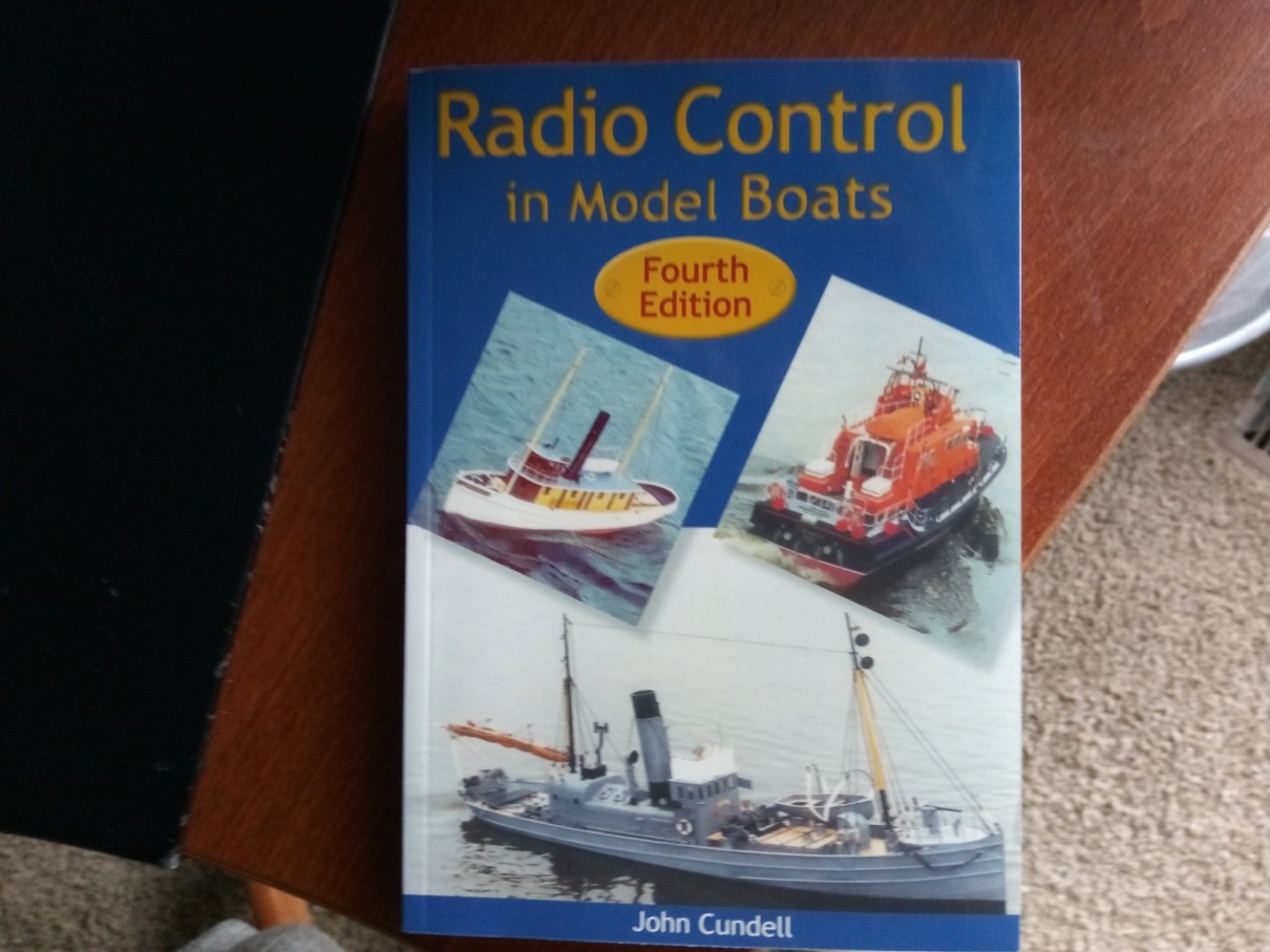


- 64 replies
-
- 7
-
-
- Seguin
- BlueJacket Shipcrafters
- (and 2 more)
-
 Good morning all, I want to share with you an alternative nice way for caulking the deck of your model ship. I used this technique for the Fifie as you can read by the thread title, but I think the best use case would be for modern era Yacht or similar. I chose this technique because this type of sealant (used in real ships) helps sealing the whole deck as this is an RC model. Precautions is never enough eheh 😁... In any case, I hope it will be useful for people out there building big scale yachts, modern ship or just want to try a new technique ⛵ Here is the link to the full video. https://www.youtube.com/watch?v=CybjsdaI1J8
 -
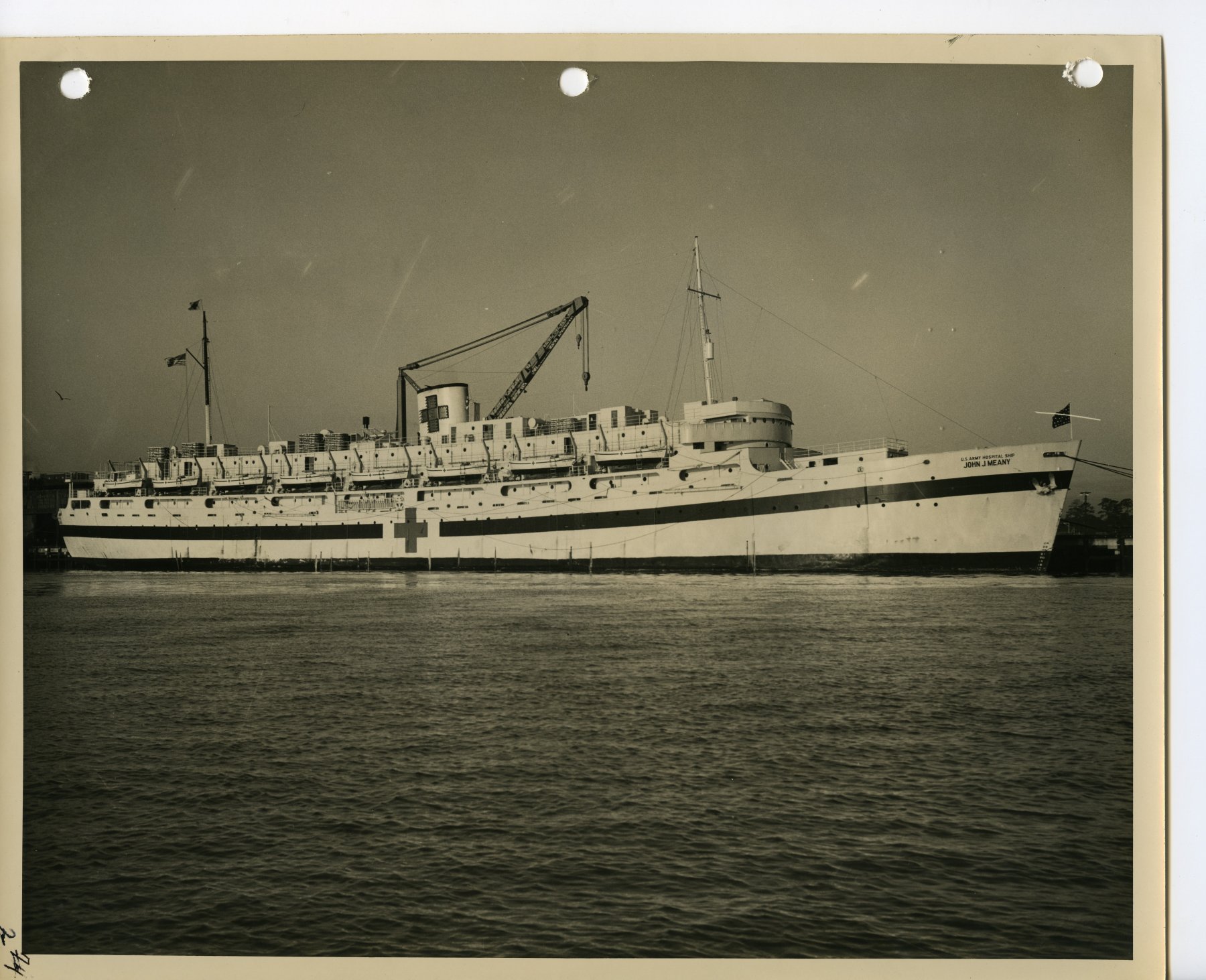
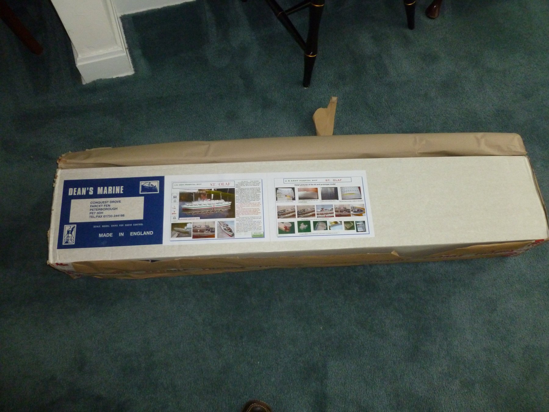
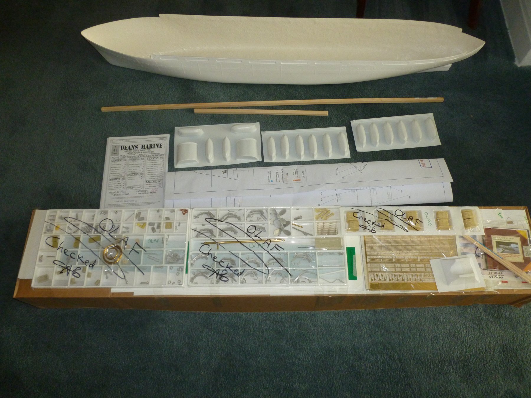
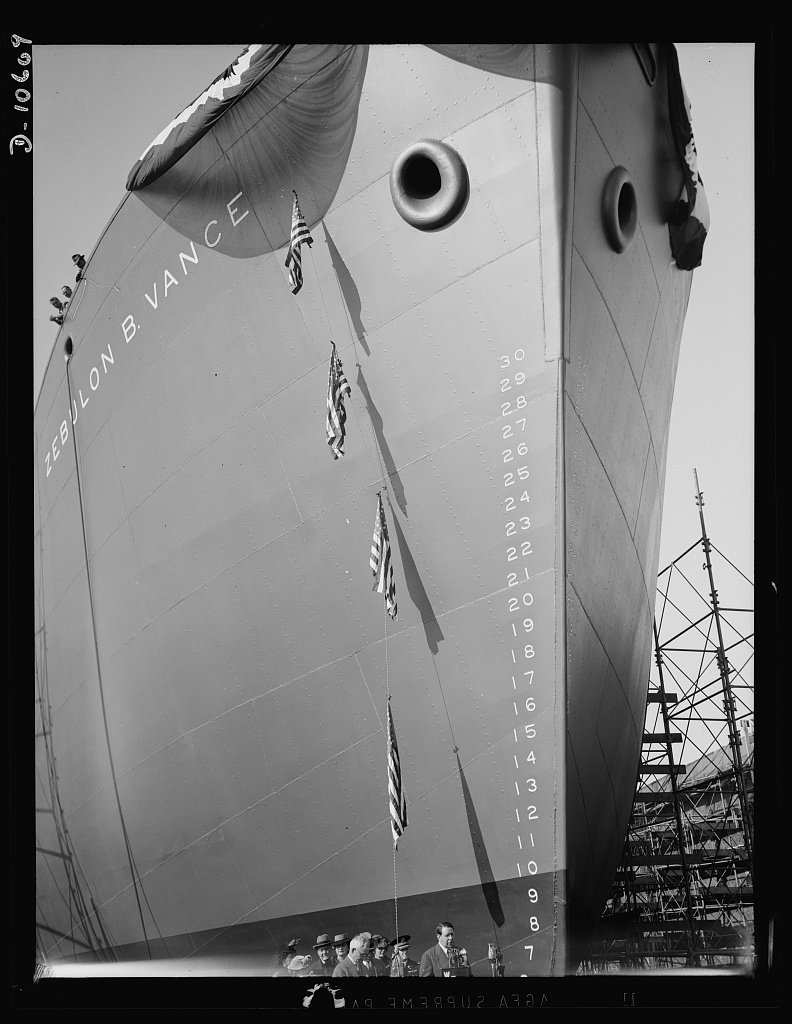
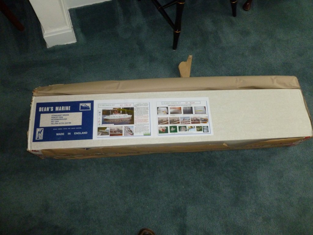
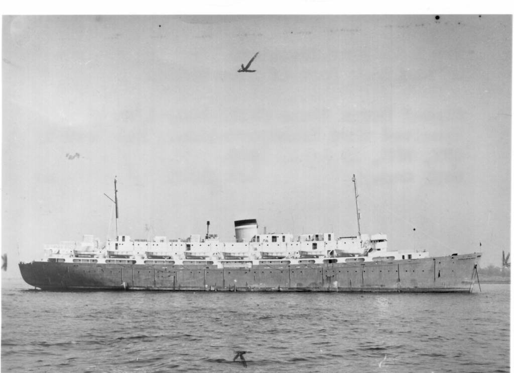
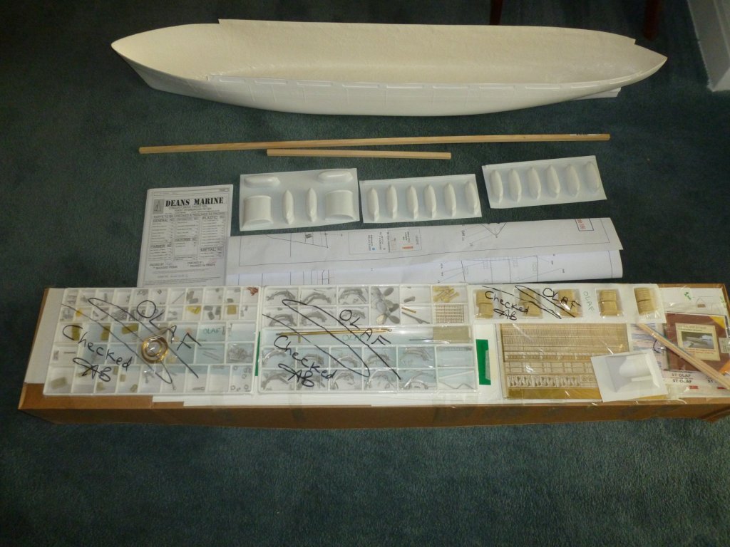
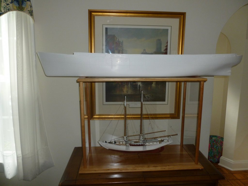
 This is a build log of the Zebulon B. Vance, based on the Dean’s Marine kit of the St. Olaf hospital ship, which was a sister ship to the Vance. My interest in the Vance was kindled when I was casting about for a new project after completing my first wooden ship build (Bowdoin by Bluejacket Shipcrafters which is chronicled elsewhere in MSW). My late mother was a WWII war bride who sailed from England to New York shortly after the war ended, and I thought if I could find and model her ship it would make a lasting gift to our family. And an interesting journey it has become. Before I get too far I would like to thank the following individuals and organizations for their feedback and assistance: James E. Atwater, Assistant Curator, U.S. Army Transportation Museum James Smailes, Ship Plans Office, Smithsonian Institution Textual Reference Archives II Branch, National Archives at College Park, MD Nathan G. Jordan, Archives Specialist, National Archives at Atlanta, GA MSW member Koa4225 The Statue of Liberty-Ellis Island Foundation, Inc. The Library of Congress An excellent book on the subject is Hospital Ships of World War II An Illustrated Reference, by Emory A. Massman; McFarland & Company, Inc., 1999; which I purchased during the course of the research. The photo above from the Library of Congress (source C. Seavey, 2017) is of the Zebulon B. Vance launch on December 6, 1941 at the North Carolina Shipbuilding Company in Wilmington, NC. The Vance was originally a Liberty Ship, the first of 90 to be built at the North Carolina shipyard. After several years of service the Vance was reconfigured to a hospital ship at the Bethlehem Steel yard in Boston, MA, one of six identical Liberty ships to be changed to support the growing need for transport and care of injured soldiers. In its hospital mode the Vance was renamed the U.S. Army Hospital Ship John J. Meany. In addition to new paint and red cross insignia the conversion added multiple decks and structural enhancements to support the new loads. The photo above, courtesy of the National Archives, shows the Meany in its hospital wardrobe. The Meany made six transatlantic voyages. At the conclusion of the last voyage to New York on January 1, 1946 the Meany was removed from hospital service and given a one month retrofit at the Bethlehem Steel 56th Street Yard in Brooklyn; to serve as a personnel carrier for the multitude of war brides and refugees traveling from England and Europe to the U.S. The Zebulon B. Vance name was restored. By this point the Vance was pretty tired and the quick changeover, illustrated in the photo below courtesy of the National Archives, did nothing to enhance its appearance. Pretty or not I’m guessing the Vance’s initial docking at Southampton, England was a welcome sight to over 500 war brides looking to escape the horrors and devastation visited upon their homeland. My mother was one of those brides who packed into the ship, three bunks high with no bathroom privacy, for the 16 day voyage. In later years she referred to the Vance as a “tramp steamer” and said she was sick the entire trip. When she arrived in New York in late February my dad met her at the dock. As they walked to the car he said, “You’re in the United States now, you have to know how to drive.” So he taught her, on the 150 mile trip north to Troy. She was a good driver after that, although I’m not quite sure how she did it after being sick for almost three weeks. I suppose it was child’s play after enduring the Blitz, V-2 rocket explosions while sitting in the park and other war traumas. So here we are. Having only one build under my belt I did not feel qualified to scratch build the Vance, nor did I feel I had the skill to kit bash a Liberty Ship model since the superstructure is so different in the Vance’s post-war configuration. I chose the Dean’s Marine kit because the St. Olaf was one of the six Liberty ships to follow the Vance’s reconfiguration to hospital ship, and because the post war Vance looks essentially identical to the St. Olaf except for paint. The downsides are the kit is large (54 inches) and the construction is fiberglass and laser cut styrene. Many of the new skills I learned with the wooden Bowdoin must be put on the shelf in favor of wet sanding, fiberglass resin and Bondo. The upside is that I have purchased the RC bits and pieces and I hope to recreate my mother’s voyage across the pond, with the pond near our house sitting in for the North Atlantic. Let’s get to it. The kit arrived well packaged, in a shipping box nearly as tall as the Admiral, and in a remarkable 4 days from England. In addition to what is shown the kit includes many sheets of laser cut styrene and a CD with a full range of photos. There are two instruction books, one more of a reference and the other more step-by-step. And about 1000 pieces of PE brass, 600 of which are railing stanchions. The Vance’s hull was placed on top of the Bowdoin case for scale reference. The Vance is 1:96 and the Bowdoin is 1:48.

- 446 replies
-
- 14
-
-
- zebulon b vance
- deans marine
- (and 3 more)
-
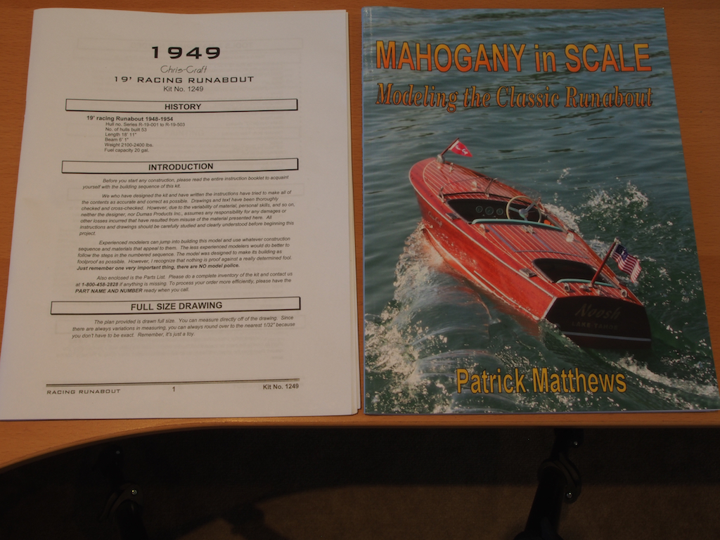
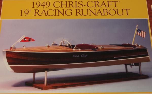
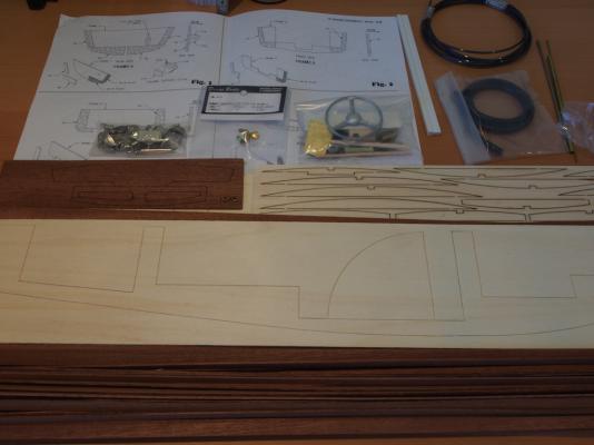
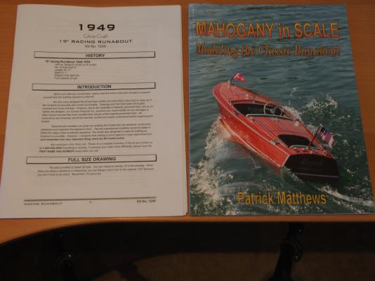
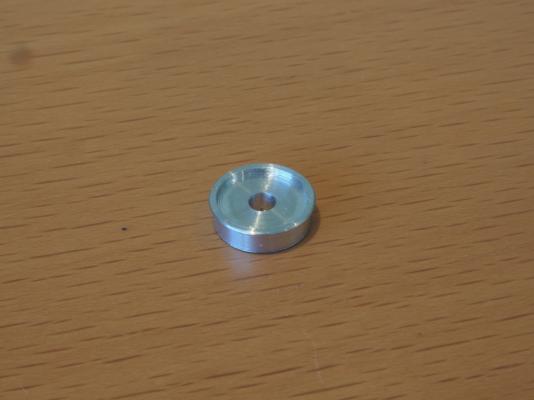
Introduction I bought this kit about two years ago, having been enamoured by the excellent build log of Rusty on MSW 1. Sadly, that build log disappeared with the “great crash”, although Rusty did re-instate the photo sequence from his build. This kit represents a couple of “firsts” for me. First up, I’ve opted to go with making this a working radio controlled model – something I’ve never done before, but the Admiral thought it might be a bit of fun and so in a way this is “her” boat. We have a pond/lake nearby and some grand kids that might also enjoy taking her for a spin (if they can wrest the controls from the Admiral, that is!) Secondly, the building of this boat calls for the use of fibreglass – something else I have never done before. What's in the box? The kit contents are interesting and appear to be generally high quality. There is a mixture of die cut and laser cut parts, Mahogany strip wood, cast metal fittings (with what appears to be nickel plating), a type of plastic board (which forms the hull below the waterline), some aluminium strip (for the trim), and some styrene strips (that form the “caulking” for the deck planks). The kit also contains all of the running gear required to make the boat operational, minus the motor, battery and RC units. These I bought separately at the time that I bought the kit. The propeller supplied is a two-bladed plastic one, so straight up I opted to purchase a replacement three-bladed brass one (you can just see this in the centre of the photo below). A set of decals, a full size plan sheet, a collection of building diagrams and what appears to be a fairly comprehensive instruction manual complete the contents. I had also come across a book titled “Mahogany in Scale” by Patrick Matthews, which is meant as a generic guide for modelling this style of boat, but uses this exact kit as the example throughout. Having read it from cover to cover (twice), it will be a great reference throughout the build. Construction - First Steps I also found a number of build logs of this kit on an RC forum (including one by Pat Matthews) and have already come across some interesting ideas for modification. A common complaint among other builders has been the use of a decal strip for the instrument panel. I have already decided that I will replace this by making my own instrument gauges. So oddly enough, having cut out a build board to commence the project, I decided to start the build by doing a “proof of concept” for the instrument gauges. It took a little trial and error with the lathe, but here is a sample of what they might look like. I forgot to add a scale reference, but this is one of two smaller gauges that will be about 12mm external diameter. I have bored out an inner section to a 10mm diameter, into which a gauge face will be glued, and I have cut a shoulder and bezel to allow it to be mounted through the dash board. The one larger gauge will have a 16mm external diameter with 13mm inner section. I have found a few pictures of appropriate gauge faces on the web, and will probably draw my own in CAD based on these. Of course, my mate Mobbsie is now trying to convince me to add LED lighting to these……………..
- 339 replies
-
- 19
-
-
- dumas
- Chris-Craft
- (and 3 more)
-
 Good morning all, This is my first post in here - my account has just been approved, so I'm going to try and start off with something I've just finished...and we'll see how this works. Long story long - (as this always is with me) I was asked by a friend if I could help make him a 3D printed ship to go with his railway layout. So, we bantered back and forth about that, and he settled upon wanting a Liberty Ship. There being a set of free plans for it available on thingiverse, I downloaded, scaled, and started printing. Liberty Ship (RC) - Revision 5 by JohnButtery - Thingiverse Thing is, I had just bought a second 3D printer (a Prusa) that let me scale it to 1/88 because it had a slightly larger build plate than my older printer...so I built my friend's on the prusa, and while it was spitting out parts, I set my older printer to knocking together a 1/96 scale version (that would fit on its build plate) and so, for basically about 3 weeks, my printers were running continuously popping out parts. Here's a 'partially done' picture: And here are the two hulls complete: As you can see in the lower photo, I also assembled and collected some hardware/running gear. The original 3D model was fairly basic, and was scaled to about 1/160, so some of the 'detail' bits were lacking when scaled up a bit. My buddy is a former RCN Weapons Tech (he fixed the 76mm OTO Meleras on our destroyers) so I spent some time modifying, then creating entirely new detailed guns and other bits to improve the models. I uploaded most of those extra bits to Thingiverse, and here is the list of all the models that are available associated to this in case anyone wants to print one of these 'kits' as well: https://www.thingiverse.com/thing:4411101 https://www.thingiverse.com/thing:5259865 https://www.thingiverse.com/thing:5259056 https://www.thingiverse.com/thing:5274078 https://www.thingiverse.com/thing:5258022 https://www.thingiverse.com/thing:5259571 https://www.thingiverse.com/thing:5274077 https://www.thingiverse.com/thing:5259970 https://www.thingiverse.com/thing:5334214
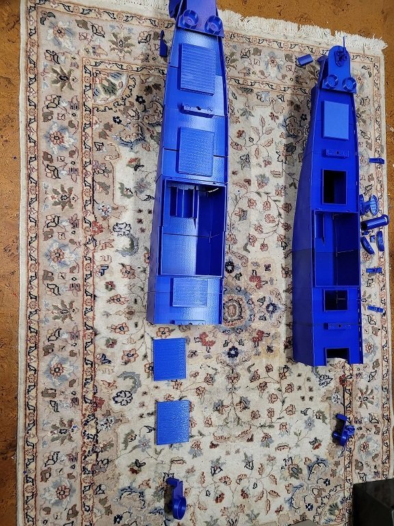
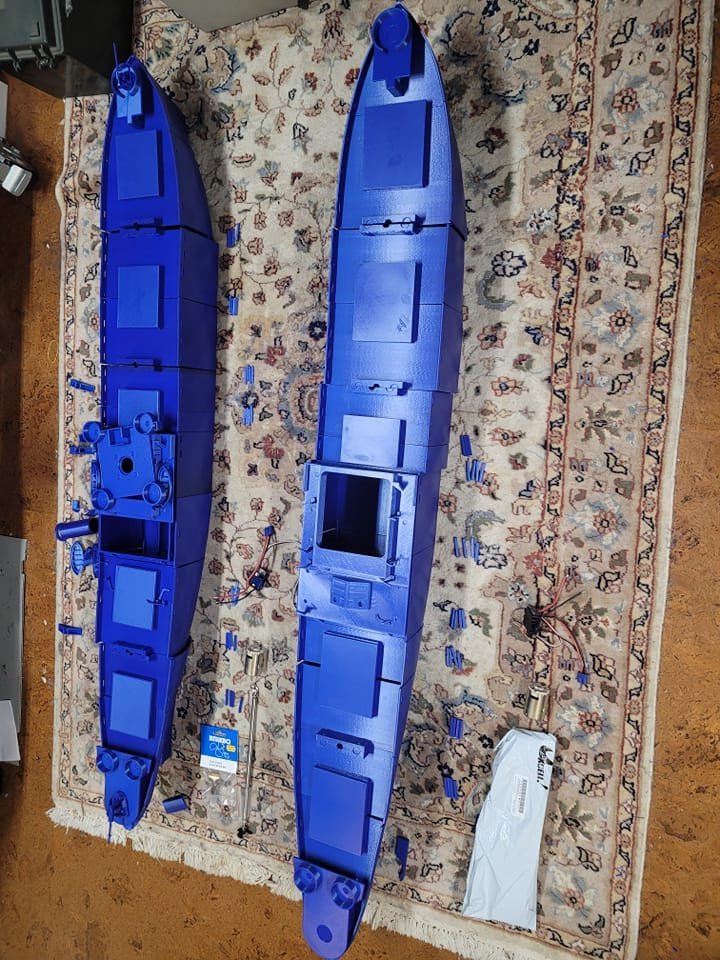
- 51 replies
-
- 8
-
-

-
- Liberty Ship
- Finished
- (and 2 more)
-
 My 1st scratch build. Zwarte zee tug built in 1/75 to match my previous build of Smit Rotterdam. After some indecision I built the internal structure using cheap plywood and 5 x 5mm stripwood. The bow was blocked in using basswood.
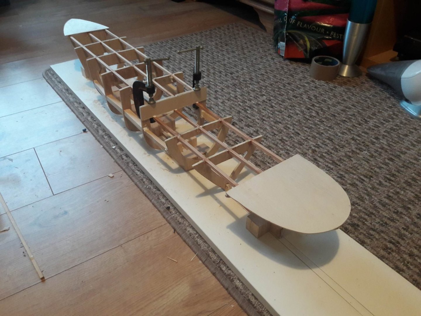
-
 My second attempt at building from a kit . . this time the Amati Dorade and I'm going to try my hand at adapting it to a basic radio control for very very occasional gentle pond sailing, so . . Here we go then . . A few years ago at the ripe old age of 70, I bought Model Shipways Bluenose. A real challenge . . totally amazing drawings of the original but a lot of scratch building. (pic 1 attached and build on another forum). This kit comes with Amati's own set of drawings, lots of shiny brass, sail cloth, threads, sheets and bundles of wood. So . . internal framing part glued but not fitted, 'scuppers' rough formed, main cabin started and planked hatch under trial . . . As I've never built anything for R/C I am on a very big learning curve . . so watch this space . . at least for a laugh !
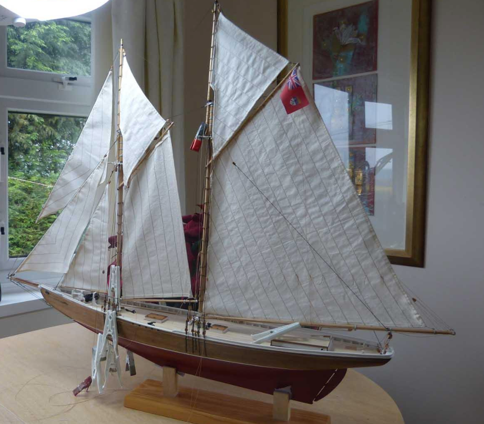
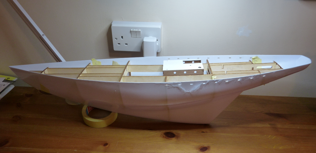
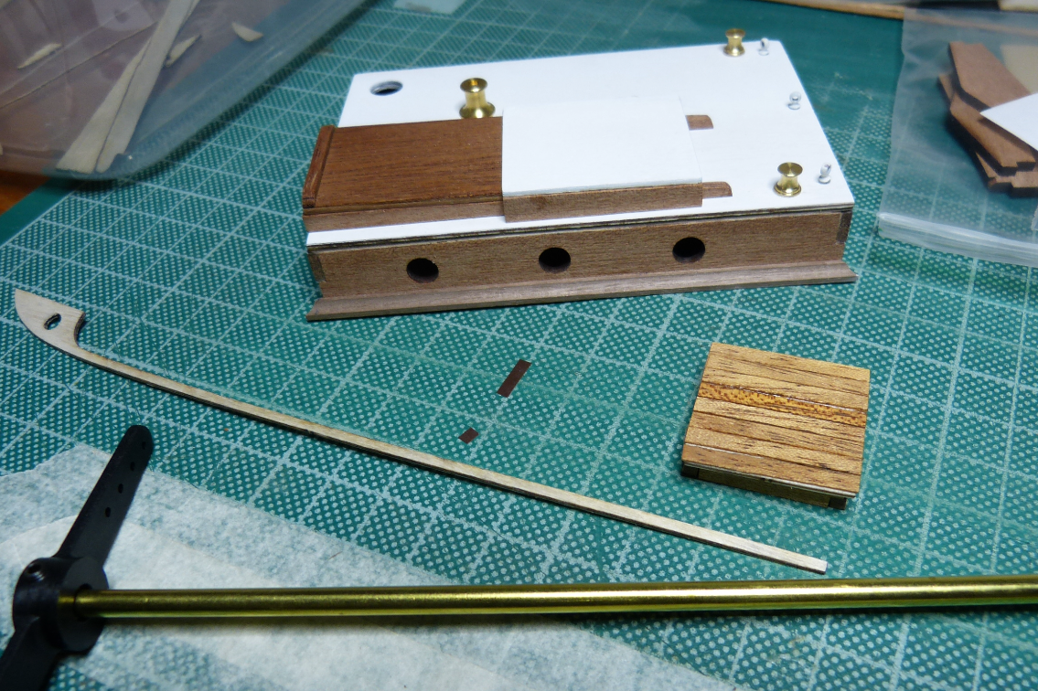
-
 This is my first scratch POF R/C work. I designed the original full-sized 40' LOD MAGIC for my wife and myself as a cruising home and she was professionally built by Bent Jespersen and his crew in Sidney, B.C., Canada. We were fortunate enough to sail her for some 25,000 miles over the course of nearly 20 years. She currently sails out of Maine and the Abacos under her current owner. In November, 2019, I embarked on this project to create a working 1/8th scale model of her. The original 3/4" = 1' scale plans had been digitized and so I took my files to a local copy shop and had them printed at 1-1/2"= 1' (200%). Like many in the forum, progress was not always steady, but we are close to being finished. If the posting of her past photos is acceptable, I will build this blog to bring the project up to date. Photo by Michael Berman Once i figure out to get the next few photo rightside up, I'll continue...
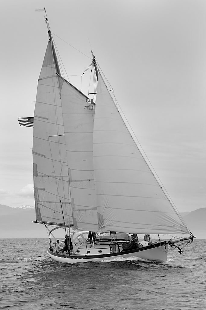
-
Hello All, As I'm in the downward section of the designing and printing the USS Maine, I couldn't help but start on the French Battleship Charles Martel. I think it's a beautiful boat and comes from an interesting time. I'm fascinated by the tumble home designs and the Charles Martel has that in spades! You can read more about the Charles Martel on Wikipedia here: https://en.wikipedia.org/wiki/French_battleship_Charles_Martel Will write more later but for now, here's a shot of the hull in work. there's not a lot of definition in the pronounced armor belt ...yet, but there will be!
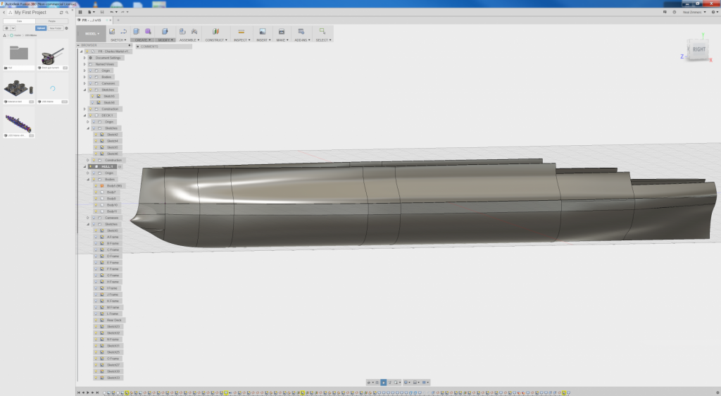

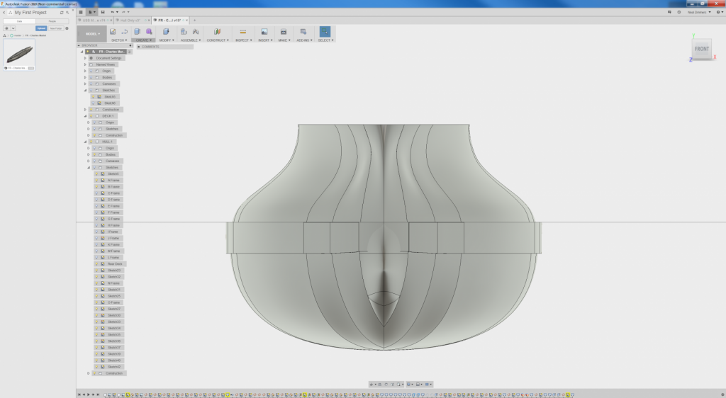
- 125 replies
-
- 7
-
-
- charles martel
- battleship
- (and 1 more)
-
This winter I’m working on a “grandfather” repair and renewal project. My grandfather was shipbuilding engineer, and was drafted in WW1, spending the war in neutral Netherlands on one of the fortresses of the defence of Amsterdam. That’s where my last project came from. From the 1920s until the end of WW2 he worked in Dutch East Indies (Indonesia) for a shipping company. In 1947 after repatriation to Netherlands he filed a patent on a method to launch a lifeboat from a davit through a clever use of a pivot. Two crewmembers each rotated a handle over 180 degrees, which swings out the lifeboat, descending slightly under its own weight. Then lines are slipped to defend it to the sea. To help him sell the patent, he had a demo model built, published an article in a trade journal, and even made a “cartoon movie” from a set of cards to show the operation. I think about a dozen ships were equipped with the system. The demo model survived the past 75 years or so, but was in somewhat of a state when I received it from a cousin before Xmas. The boat is solid. Just needed a paintjob but is unsuitable for radio control. My plan has three phases - repair the model - build a RC controlled new lifeboat to be launched from it - possibly make the Davit RC as well the repair was fairly straight forward, involved re-soldering the brass and copper past, new paint job and polishing up the blocks and brass parts. in the last photo, the solid wood boat is half painted, I decided to make a new boat using “plank on frames”. The new boat will be slightly shorter with room for a rudder, and will have a prop obviously. To obtain a plan of the frames, I marked out frames on the keel of the boat model, and used a home made measuring device to measure out the shape of each frame. from that I drew the frames on a 7mm pine plank, and the keel on another one (slightly shorter and with opening for the prop). also the planks themselves were sawed from pinewood, and I’ve just started mounting the frames and keel on a build plank for planking. TBC…

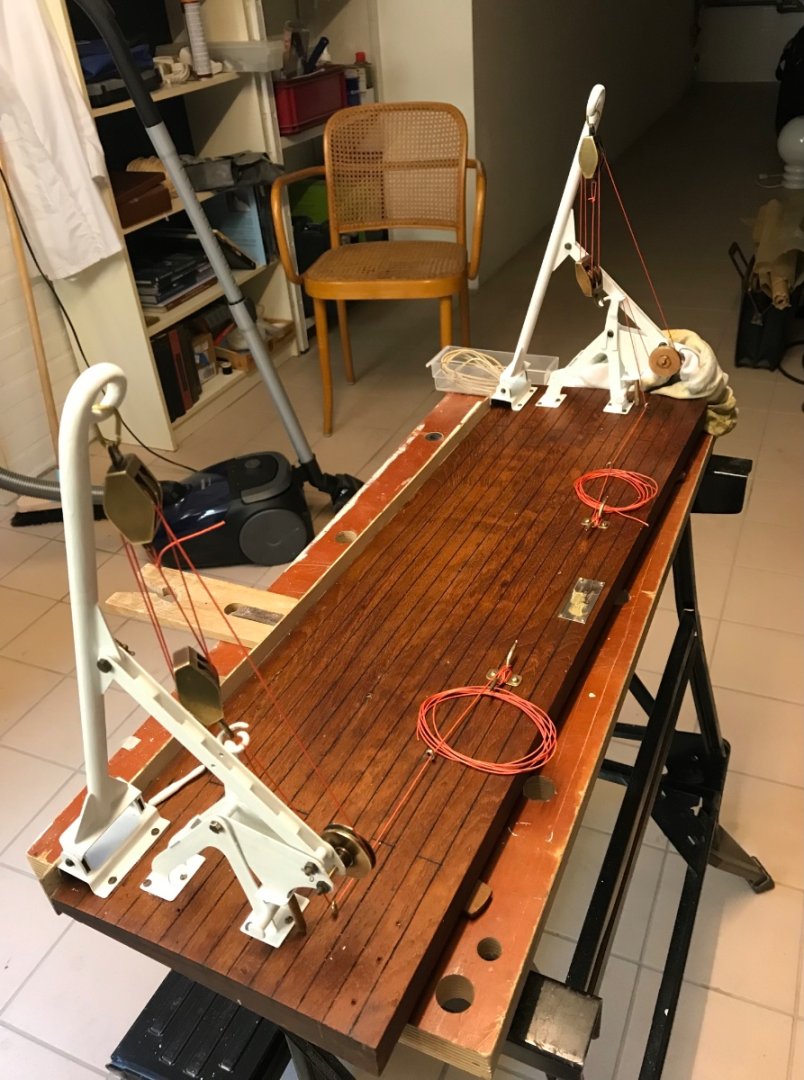
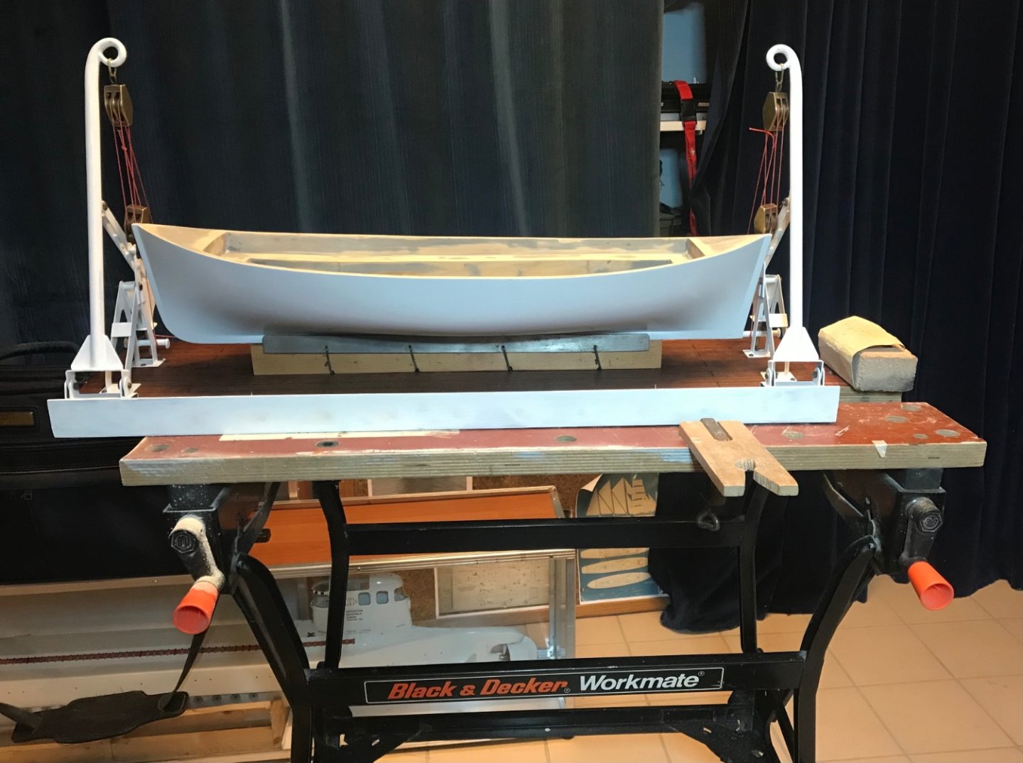

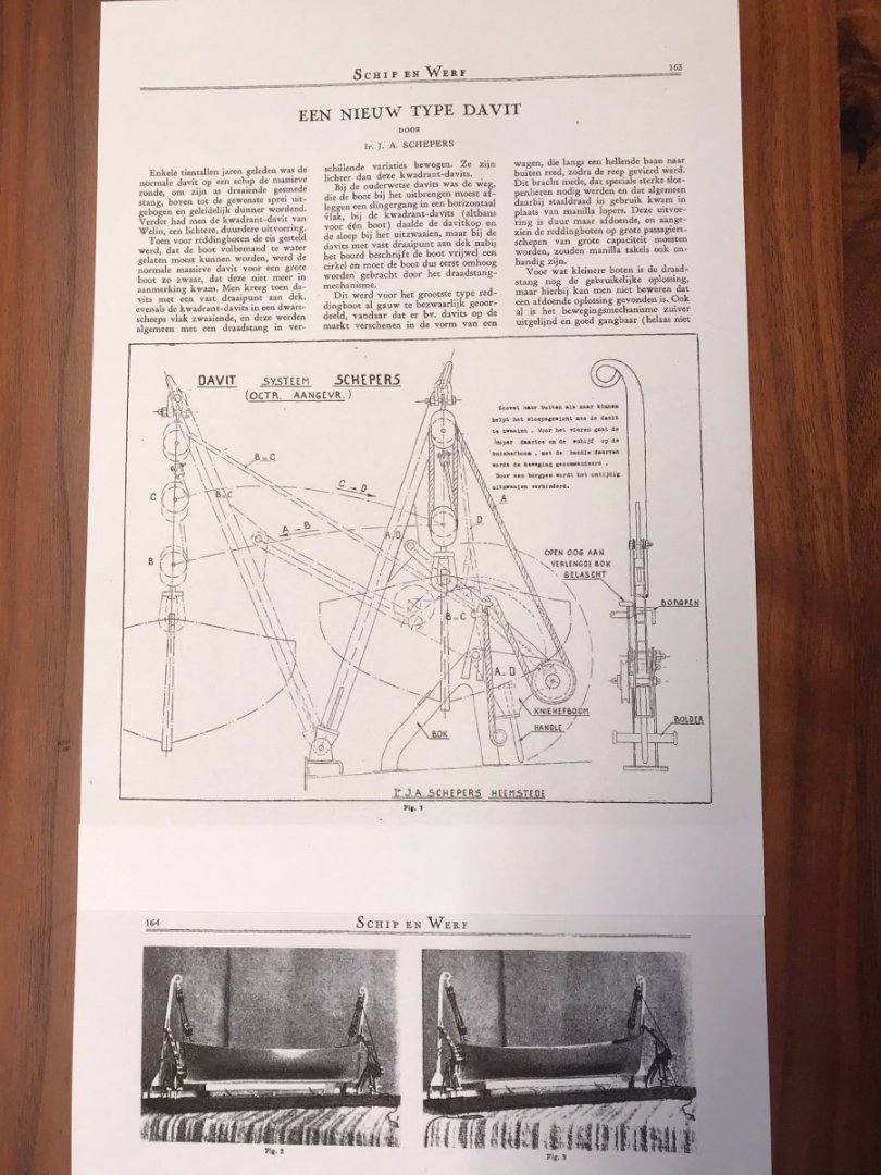

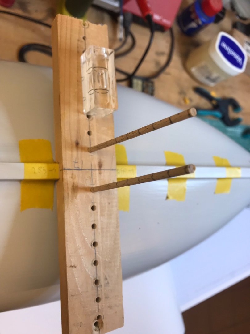


-
 Greetings Fellow Model Ship Enthusiasts! A few years ago I crossed Lake Michigan on the last commercial coal-fired steam ship on the Great Lakes; the SS Badger (410 foot long ship launched in 1952, a passenger and vehicle ferry crossing from Manitowoc Wisconsin to Ludington Michigan). The smell of the coal-fired boilers and my fascination with the design of the steam powered engines left me with an interest in learning a bit more about steam engines, so I set out to build a model steam engine, and then of course I figured I would need a little boat to put my engine in, which leads me to this build log. For the steam plant, I went with the "Clyde" by Miniature Steam Models (MSM) in Australia, and for the boat, I selected the "Alexandra" by Krick (German manufacturer). The Alexandra is about 3 feet long, and is a model of a English Steam Launch from 1900. I have been working on this since January; with work and kids I do not make quick progress. I have taken many photos during the build, and it being the end of November now, I will have many photos added to this build log all at once. More detail, especially on the assembly of the engine, may be found at https://www.argobuilder.com/krick-alexandra-steam-launch.html From here on out , I will try to post more regularly so the build log will follow along with the construction of the model. I would rate the Krick as a high quality model which can be greatly enhanced with some additional trim and planking work. The plywood pieces are high quality but left as-is, I think the exposed plywood edges, exposed plywood mortise and tenons, and large flat plywood surfaces, are much improved with hardwood planking and trimwork, as can be seen in the build log below. And now, on to building the Krick Alexandra Steam Launch! Jason
 -
 Hi all, after the original forum, where I started posting our build log, has become very silent, I hope to find a more interested audience here! I have been persuaded by my son, then 8, to build a wooden model ship (he had been inspired by seeing a wooden model of a Minoan galley, shown in a excavation museum found on the Greek island of Paros - a reconstruction based on murals 3800 years old). As we were reading a book on Francis Drake at the time, it had to be a sailing ship of roughly that area, of course remote controlled, of course with functioning cannons, and reefing sails was also a desired feature. A good friend of ours builds cardboard models, he gave me a cardbord model kit for the Papegojan from 1624, scale 1:98 - the plans of which I stretched by 320% (such it will just fit into the trunk of our car - and the bigger, the better for real sailing). Our model measures ~1200mm from stern to tip of the bowsprit, and displaces 9.6 kg. Also, we changed the name to "Zeta", and made some minor modifications to the original, as preferred by my son. Apart from that, we have tried to stick as much as possible to historical correctness as possible - with some small compromises to allow radio controlled sailing - I will point these out. For sailing, all sails will be contolled as in the original, with the help of bracing winches (I hope this it the correct English term). Sails also allow reefing, not fully historically acurate, for reasons of mechanical implementation, but more or less close to it. Cannons can be fired remotely, and are also planned to allow running in and out of the ship, gun ports opening and closing respectively. At this time, the hull and all details are complete, so is the rigging - what is missing are the bracing/reefing reels to complete the sail steering unit; the mechanical and software part for cannon control, and the lead ballast. Here are some teaser pictures: if you are interested in a detailed build log (we learned a lot on our journey), let me know, and I will translate the original log (in German) and continue posting here! (As this is our first model, and there were many things we did not initially know about model making as well as about historical sailing ships, we have created a comprehensive log with a lot of explanations, as I felt the relevant information did not exist in a single place elsewhere.) Greetings from Vienna, Austria, -Roman