All Activity
- Past hour
-
 Baker reacted to a post in a topic:
Ferrari 288 GTO Yellow by CDW - Fujimi Enthusiast Series - 1:24 Scale
Baker reacted to a post in a topic:
Ferrari 288 GTO Yellow by CDW - Fujimi Enthusiast Series - 1:24 Scale
-
Baker reacted to a post in a topic:
Ferrari 288 GTO Yellow by CDW - Fujimi Enthusiast Series - 1:24 Scale
-
 wvdhee reacted to a post in a topic:
Chris Watton and Vanguard Models news and updates Volume 2
wvdhee reacted to a post in a topic:
Chris Watton and Vanguard Models news and updates Volume 2
-
TJM reacted to a post in a topic:
HM Cutter Alert by Thukydides - Vanguard Models - 1:64 - first build
-
Baker reacted to a post in a topic:
Ferrari 288 GTO Yellow by CDW - Fujimi Enthusiast Series - 1:24 Scale
-
Baker reacted to a post in a topic:
Cat Esther by GrandpaPhil - 1/64 - CARD
-
Scottish Guy reacted to a post in a topic:
Hello from Michigan
-
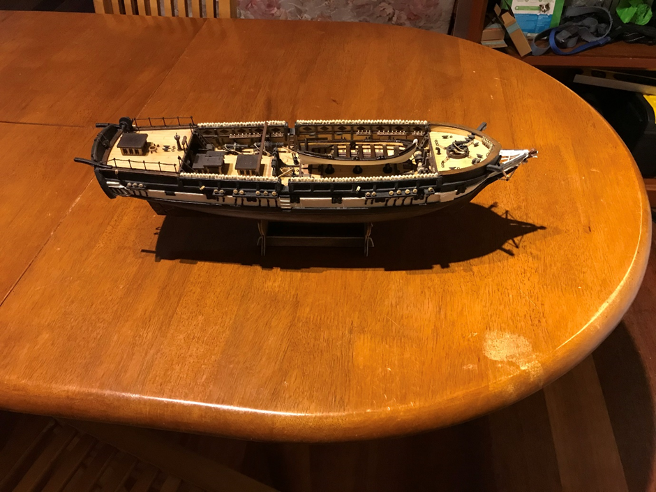
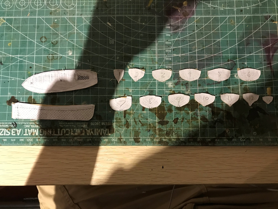
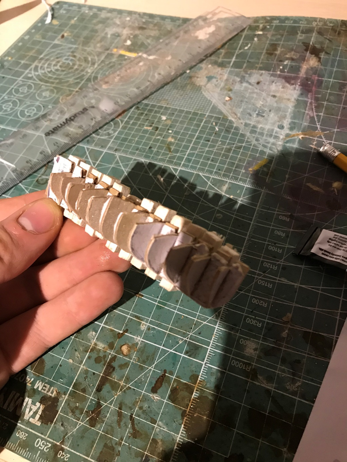
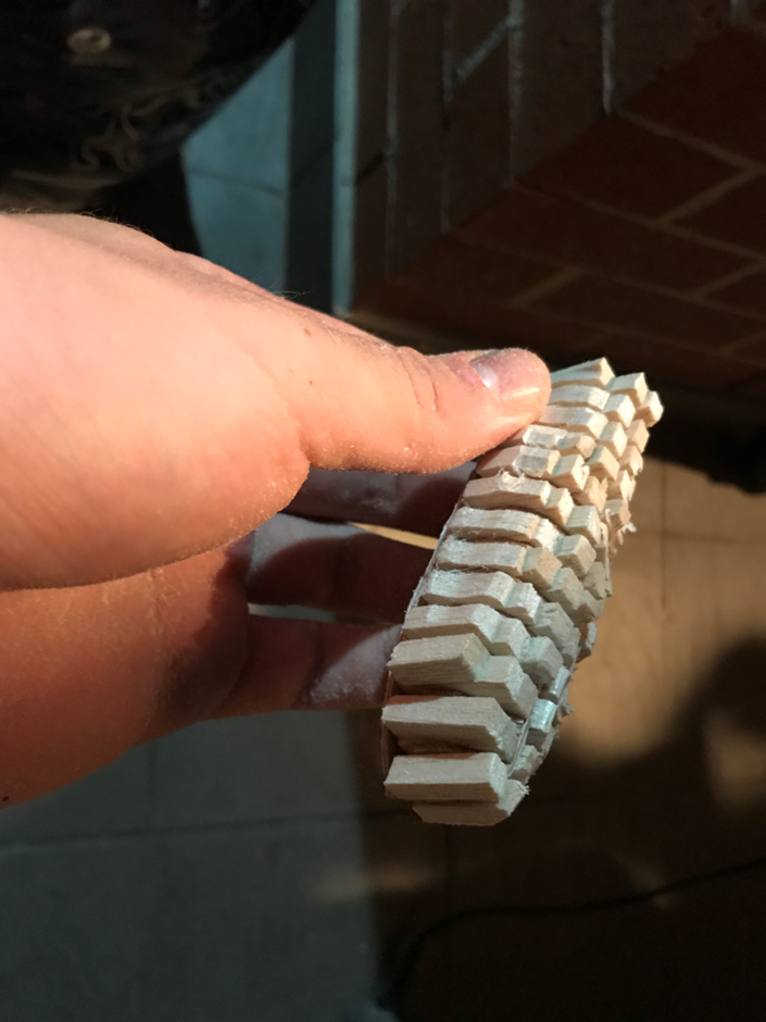
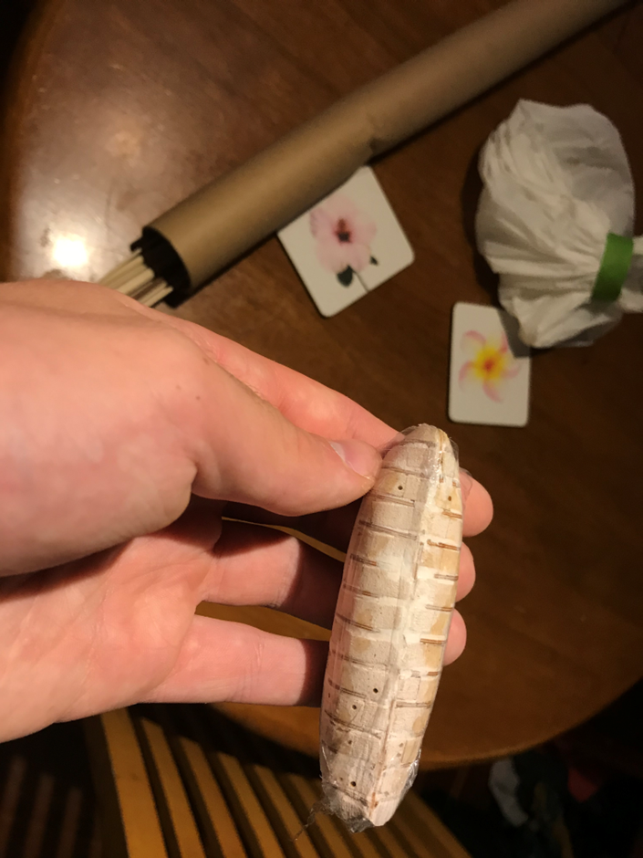
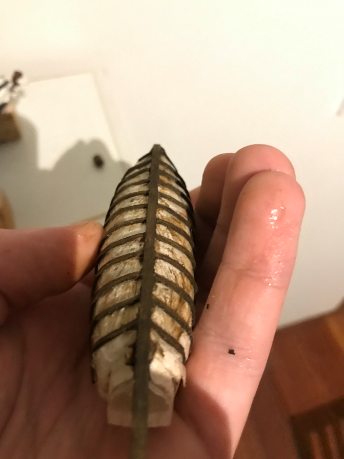
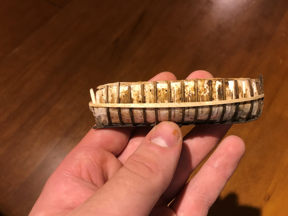
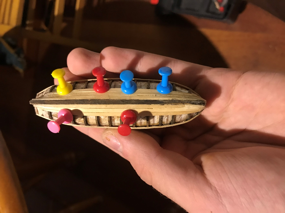
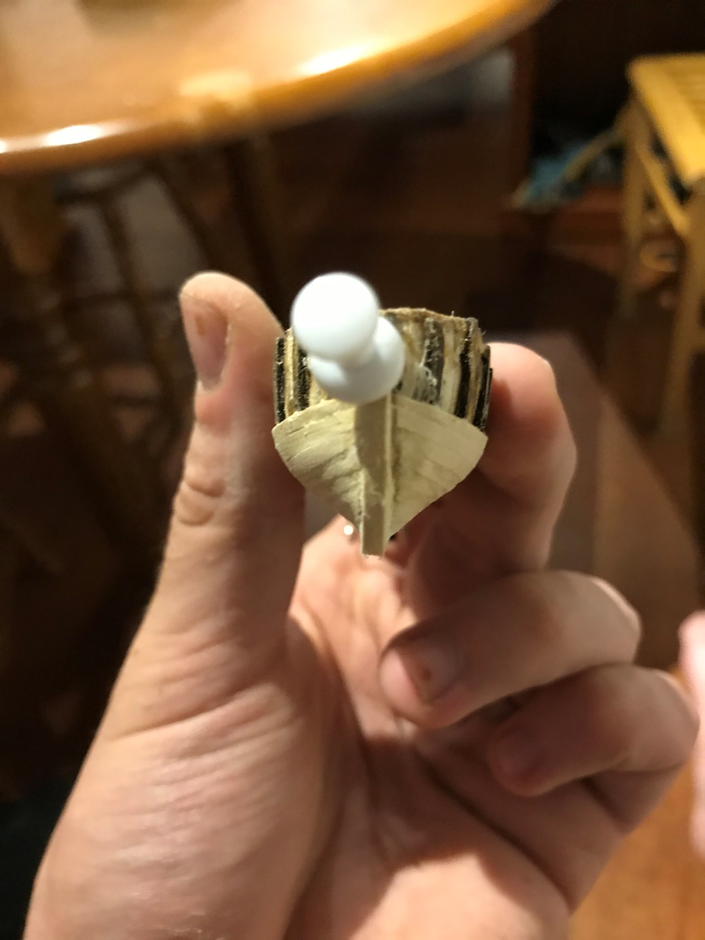
 Okay, so it’s been a while, but I haven’t exactly been idle. Over the past year and a bit I’ve been continuing to work on the Beagle’s boats. In my last post, which was January of last year, I had finished up the yawl. The next steps were to make the chocks for it on the ship. I next started on building the cutter that would have nested inside the yawl. This would have followed a similar construction plan, so it made sense to do it next. Similar to the yawl, I printed out the plans and used these to cut the pieces of jig I glued these into a frame and filled the gaps with balsa Then I sanded it back to the frames. I also thought it might be a good idea to add some glad wrap this time as I had such a problem getting the hull off the jig last time Then came lots of bending and staining frames to create a platform to lay the planks on Then planking Unfortunately, it was only at this point I decided to size the boat up next the yawl I had already made. I’m not sure how it happened, but the plans I printed out were too small, which resulted in the ship having significantly reduced dimensions compared to the yawl. I spent plenty of time trying to determine whether I could live with this. Ultimately, I figured that the scale problem would likely only become worse as I proceeded and make it more difficult to fit all the deck planks and thwarts into the boat at the dimensions I wanted. I decided to bite the bullet and start over. This caused a big break in progress, so when I eventually came back to the ship, I decided to try to make all 6 remaining boats in parallel to move the project along a bit faster.
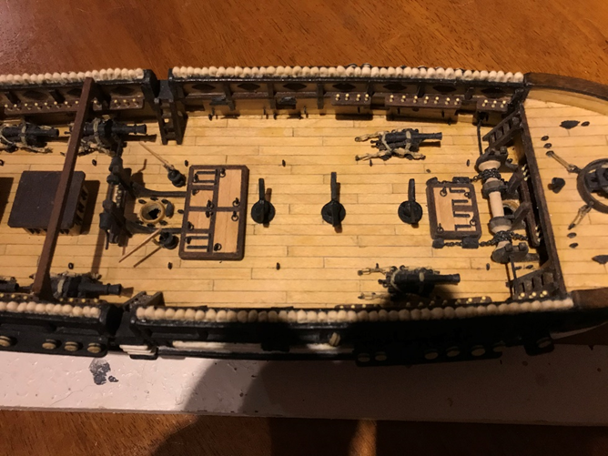
-
 I puzzled over this for a long time as well but for the life of me I can’t remember what the solution was. I am away from home until next week and will get back to you when I have a look at my model and plans. Hopefully David will lend his guidance before that. You are doing a great job so far. Best, Ian
 -
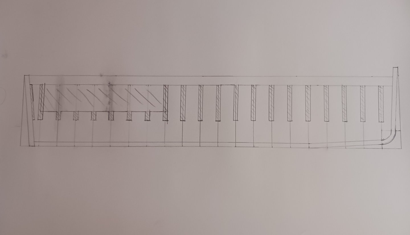
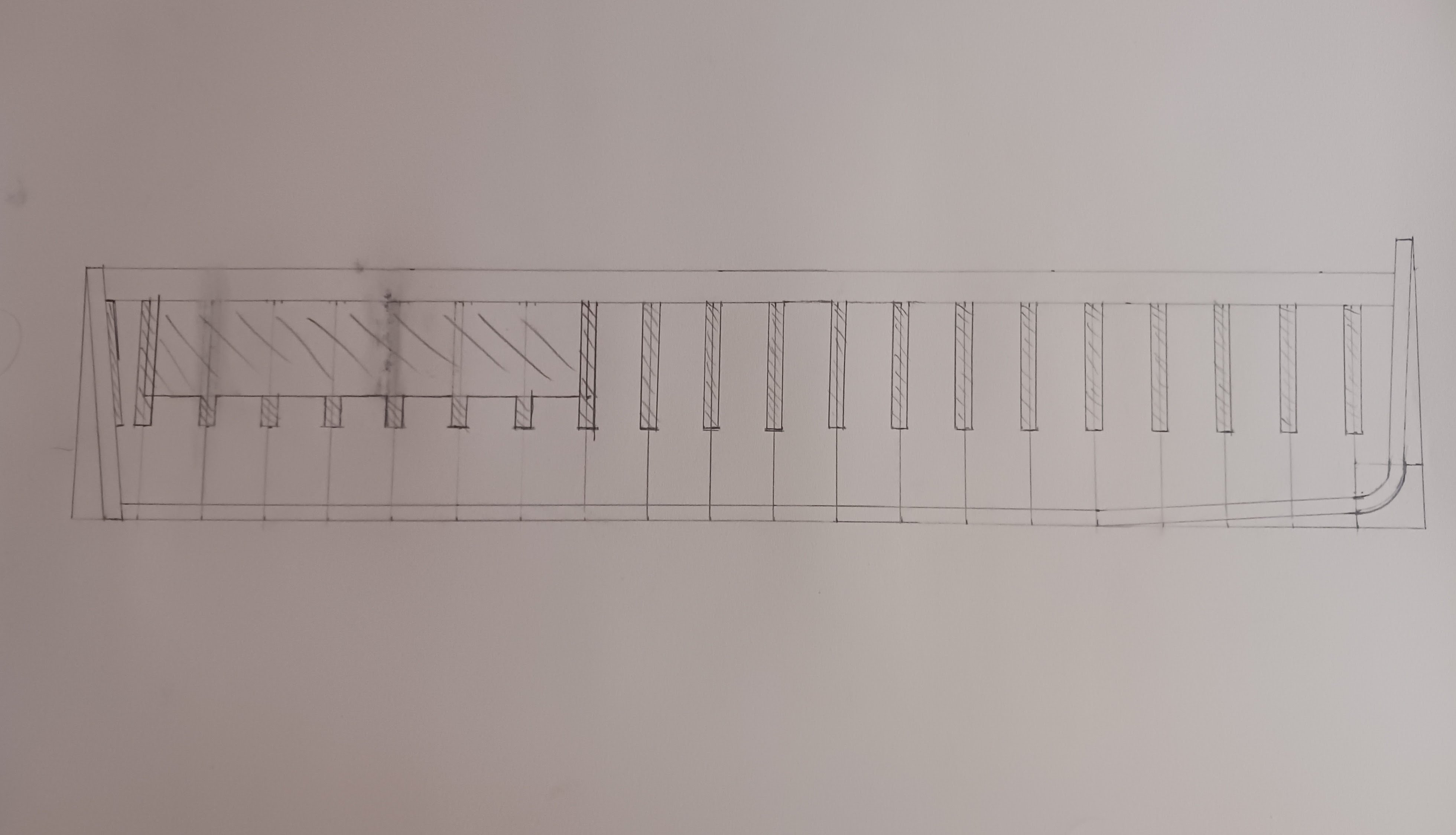
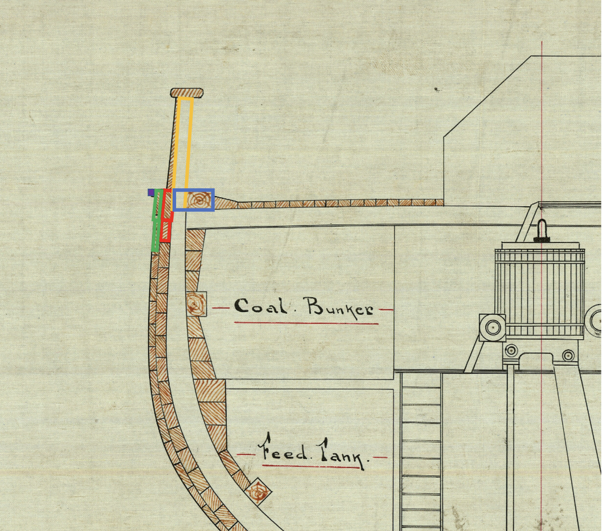
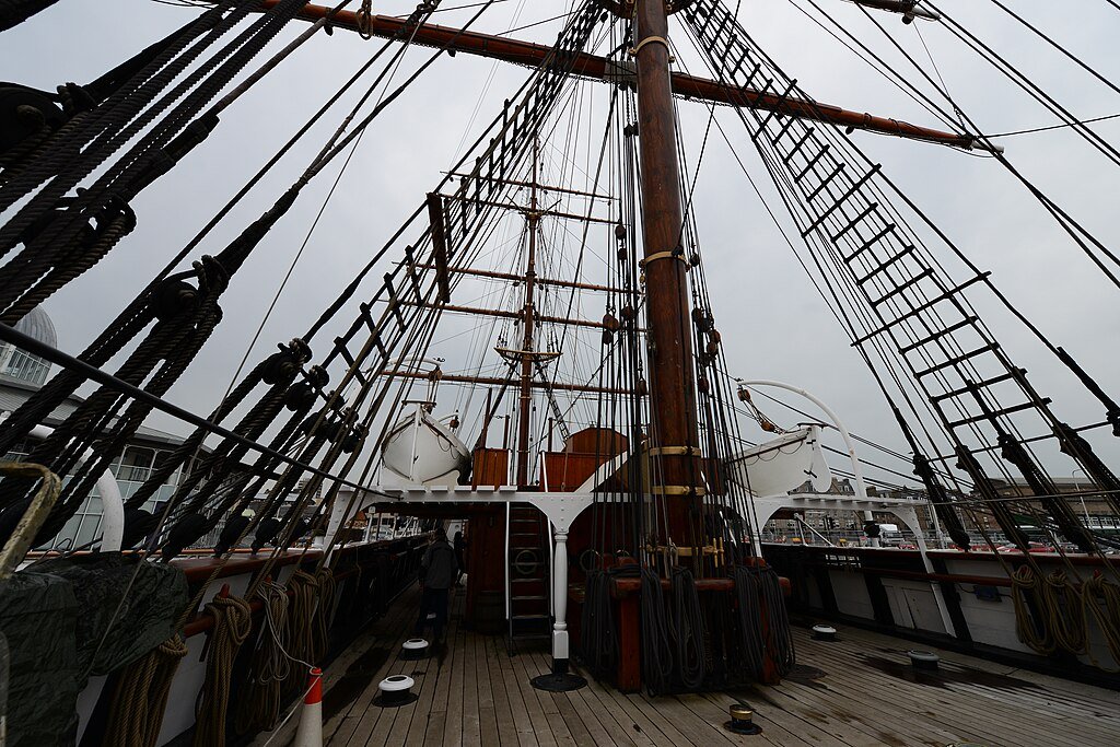
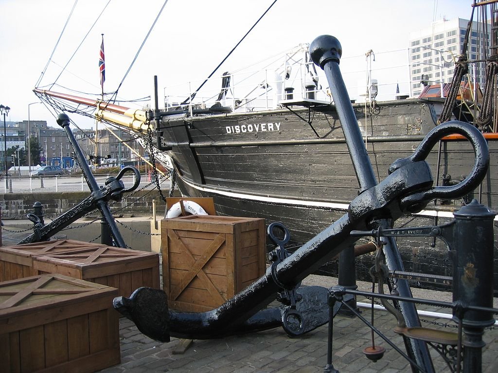
 Thanks Peter. It has a long way to go, but there is definitely something fun about designing it yourself. In my case, it probably means I'll do a lot of stupid things, but hey, we learn through our mistakes. Isn't that the truth. The bass knightheads were way softer. The good news is that the stern is going nowhere; it will be a nice solid platform to build on. On the update side, I haven't had a ton of time to work on the ship - there have been some things at work and my wife and I have been doing a major declutter associated with our 15 year anniversary at this home, and based on the fact that I'm pretty confident that we are truly, truly empty nesters (the younger child is going to be leaving her job in Boston to start graduate school in nursing in Philadelphia at the end of the summer, so I am not anticipating her moving back in anytime soon). As part of that, I'm moving my work space into a different location, so we can better use the rec room that I currently work in, etc., etc. However, the move is more or less complete, so back to making sawdust. I did finally finish the filler blocks, so she is ready to start the process that will generate the hull. I've designed her more or less as the Flying Fish kit I built was designed. On the Fish, I laid the waterways on the bulkhead tops flush with the outer edges of the bulkheads, and then the planksheer (cut for the bulwark stanchions) was laid on top of that. The nibbing strake was flush with the waterways and on top of the bulkhead, and the deck laid directly on the bulkheads. This ship is designed slightly different. If you look at the below you will see that the planksheer is kind of integrated into the planking itself, and in addition to the waterway (angled plank), there is a fairly significant timber that is mounted against the frames. As it happens, at 1:72 that timber, plus the extension into the frames works out to 1/4 wide and 1/8 inch tall, a nice, even size that is readily available in bass. So, my plan is as follows: I will build the timber that abuts the waterway and the extensions to the outer edge of the frames from a piece of 1/4 x 1/8 bass, cut to allow a bulwark stanchion to fit (they are spaced about 0.7 inches at scale center to center between the stanchions). This is the blue box on the diagram and it will be aligned with the outside edge of the bulkheads. I will run it for about 22 inches, until the curve becomes too great to efficiently bend, and then will cut out the stern curve with my scroll saw from some 1/8 inch thick basswood. The two layers of planking (red and green) will be added as normal and then a 1/32 inch piece of square bass (purple) will be added on top. Finally I'll make the bulwark stanchions (yellow) out of 3/32 bass and fit them into the slices I cut out of the large 1/8 by 1/4 x 22 piece. One thing that I will need to be careful about is ensuring that the bulwarks have the correct angle, because the ship I think that will work, and produce something that resembles the real thing as below: Photo by Michael Garlick, retrieved from Wikimedia Commons (https://commons.wikimedia.org/wiki/File:RRS_Discovery_Dundee_Main_mast_rigging.JPG) under license CC-BY-SA-4.0) One thing to note is that the Discovery in common with a lot of other ships of that era has "floating" bulwark extensions, that is, they were separate timbers that were not extensions of the frames. Since the bulwarks tended to rot faster, it was simpler to seal and maintain them if all you needed to do was pull a single timber out and not have to mess with the frames. That will not be obvious from the model, but it is the way that the ship was built. Also interestingly, I had assumed that the extension that I am modeling as the 1/32 square plank was where the white stripe was painted, but looking more carefully, the stripe is actually painted just below that plank, and it points to something I need to be careful about - the angle of the bulwarks. If you look at the photo below, you will see that the ship doesn't really have channels where the chain plates are, so making sure I have adequate clearance to drill the holes for the chainplates is going to be important. Photo by Magnus Hagdorn, retrieved from Wikimedia Commons (https://upload.wikimedia.org/wikipedia/commons/thumb/5/55/2007_-_Trip_to_Dundee_(4000147227).jpg/1024px-2007_-_Trip_to_Dundee_(4000147227).jpg) under license CC-BY-SA-2.0 generic) Anyways, as always, thanks for looking in! Please let me know if I have mangled the terminology somewhere. Regards, George
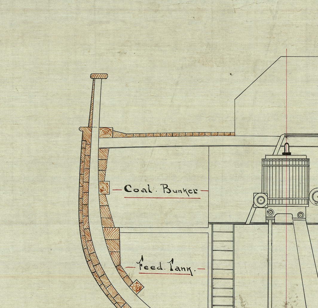
- Today
-
Hi Ryan, Welcome aboard, I'm still fairly new here as well and unbelieveably from the outskirts of Grand Rapids myself...small world as they say. Look forward to seeing some of your work!
-
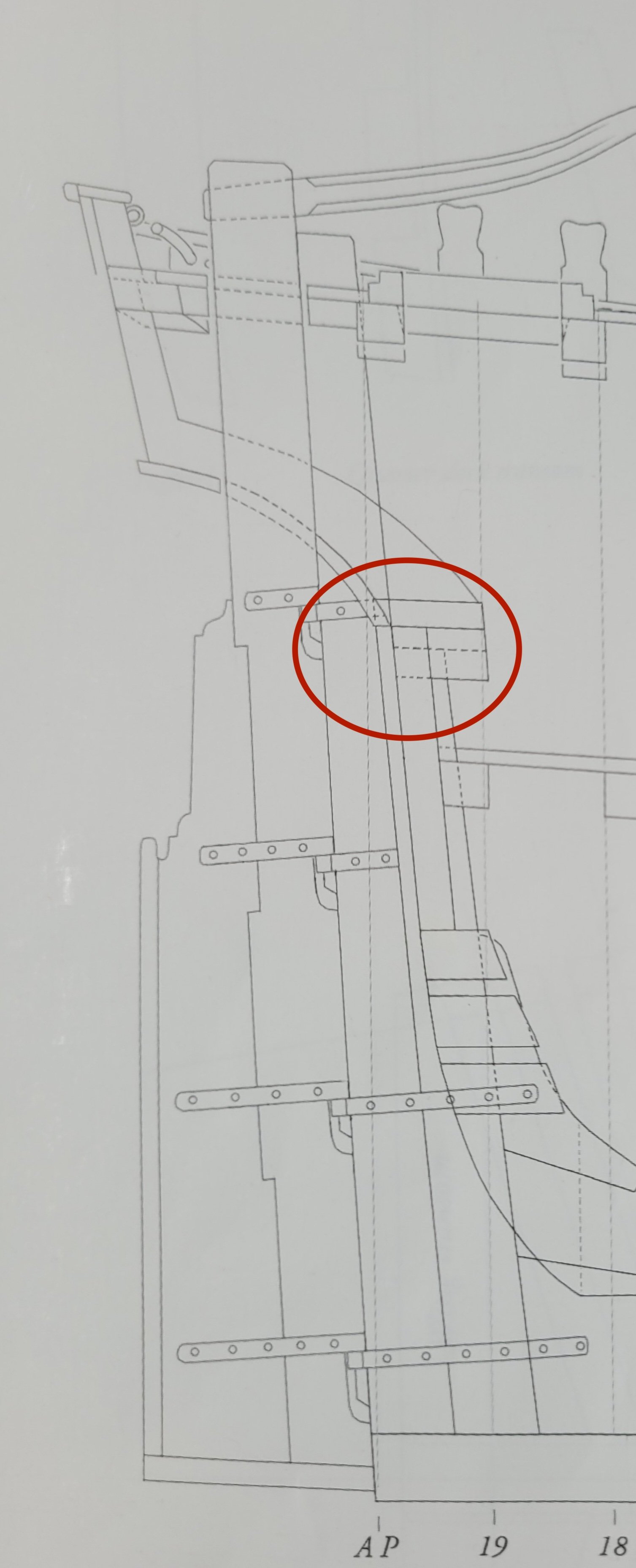
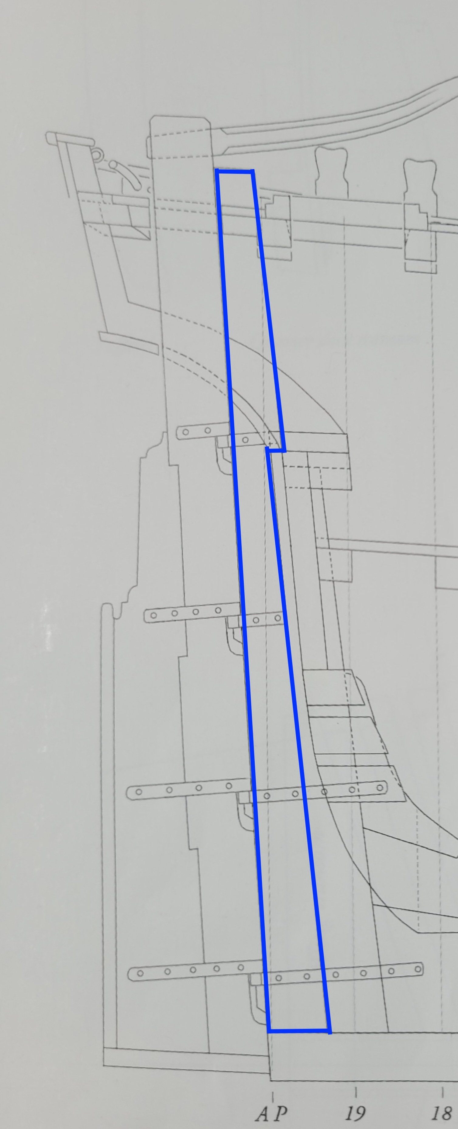
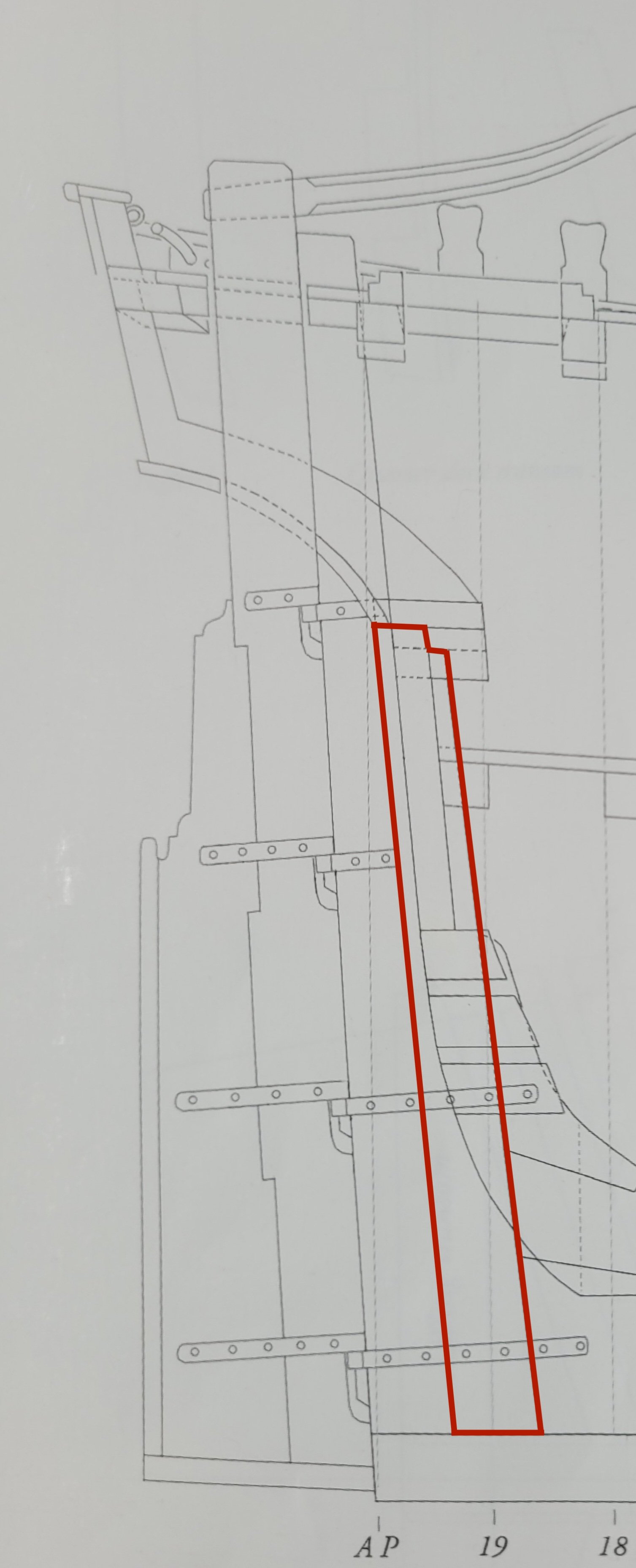
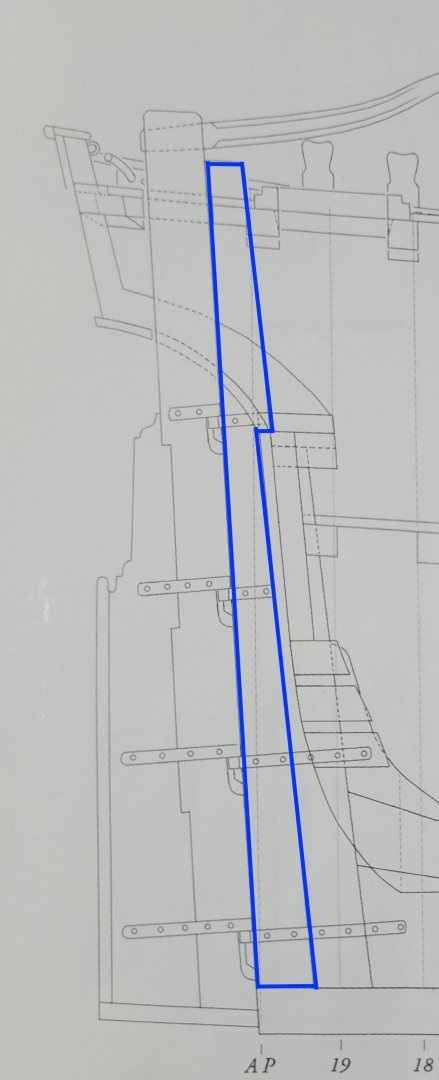
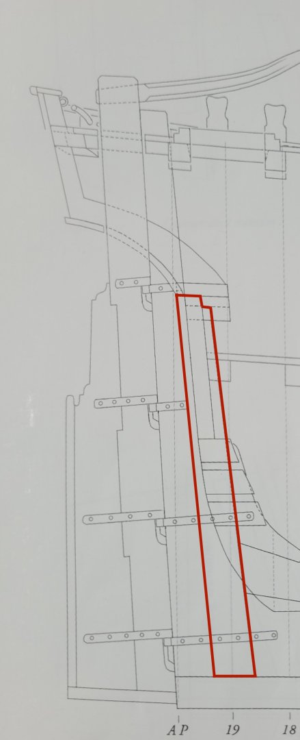
 Hi folks, I have been puzzling over the plans looking at the sternpost and the inner post and I'm having a bit if difficulty understanding how they are shaped where they meet up with the wing transom. This part of the plan has lots of lines for all of these various parts and I'm not sure sure which one is which! Here is a scan of part of the plan and it is this area in the red oval that I am struggling with. The sternpost shape is, I hope fairly obvious, and I have marked it in blue in the scan below. It appears to me to have a little 'hook' where it sits on top of the top of the inner post which is where the rabbet ends I believe. Is that correct, do you think? It is the shape of the top of the inner post that is confusing me the most as it appears that this is where the wing transom sits. I have marked out what I think is the correct shape in red below but looking at the illustrations in David's book the top of his sternpost seems to be complete flat, rather than having that little step? I fear I am missing something here and hopefully that may be obvious to more of you than it is to me! Any advice and guidance would be most welcome as I would like to get theses pieces cut out of the stock. I thought I had it all sussed out originally but the more I look at them now the more confused I get - so some fresh perspectives from you all will certainly help. Many thanks in advance 🙏
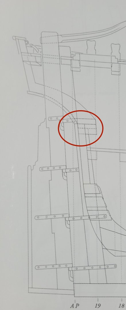
-
 It is looking really nice. One question: I miss the different knees, especially where the guns are situated. David has shown them in his drawings. Why do you have omitted them?
 -
 Craig, as I look at the second photo you posted, it looks to me like the guys may be attached to the boat davits. Which makes no sense since the plans I have found online and OcCre position the davits aft of the funnel. Maybe sometime late in the journey the davits were moved forward to be in line with the funnel? All of this assumes I have my shipboard geography right. As I look at that photo, it is facing aft from just forward of the main mast, and the sort-of-round things in the middle are, moving aft in the picture, the mainmast forward gaff, the main mast, and the funnel. Further aft you can’t see the mizzen mast, but you can see its ratlines. This assumes that the intake funnels have been rotated to face aft, unlike the first photo where they face forward and seaward. Any thoughts?
 -
 I used self adhesive copper foil tape. I remember I shared a few photos in my build log about how I implemented it. (Something like in the link below) https://tr.aliexpress.com/item/32876412753.html?src=google
 -
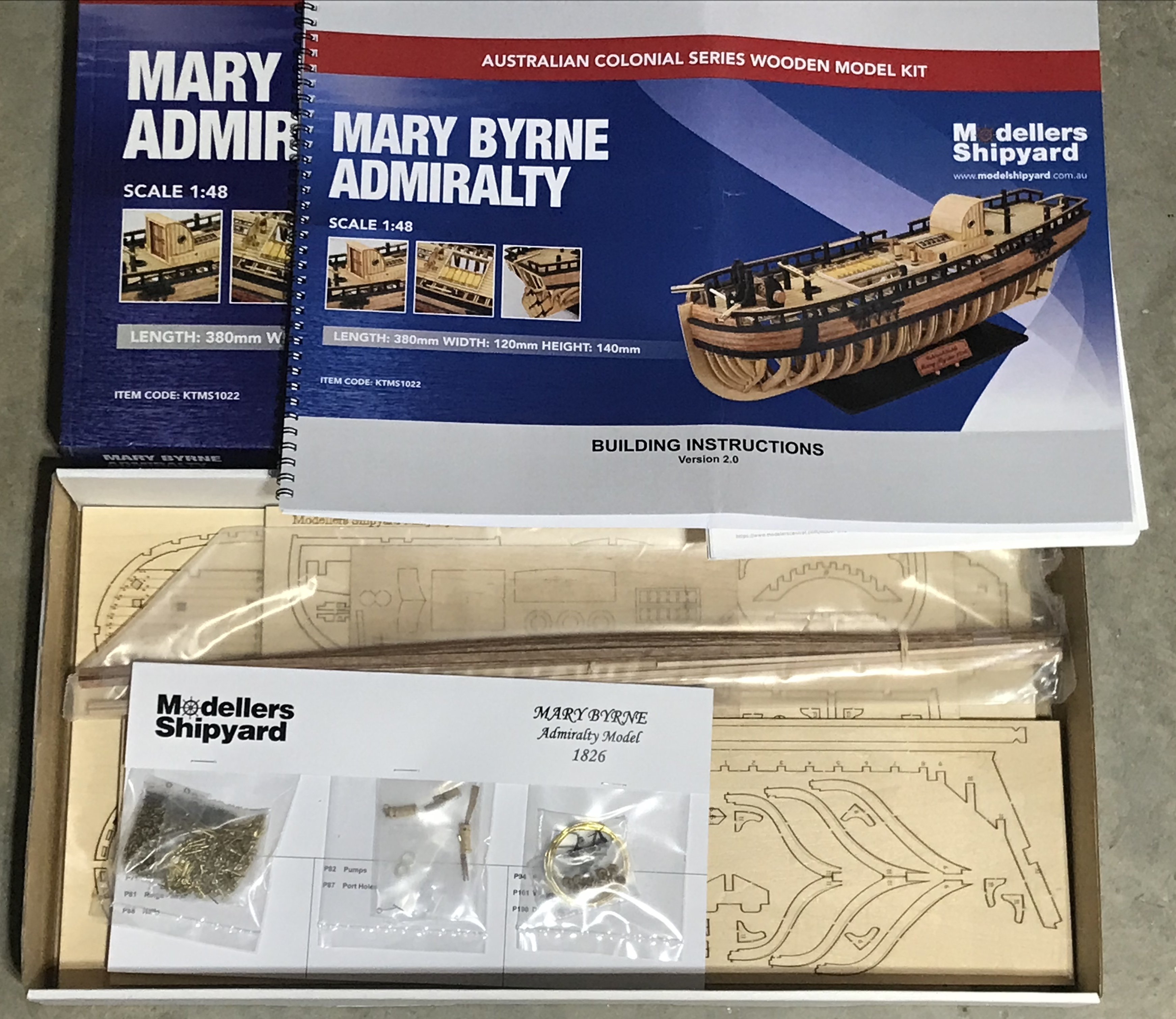
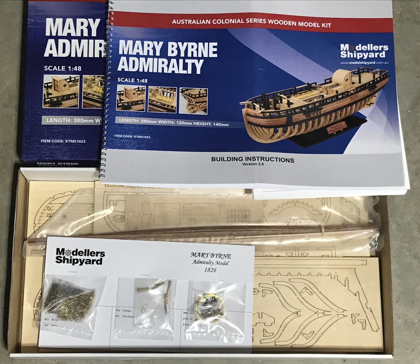
 This is an “opened for inspection” copy of the lovely kit of the Mary Byrne, an Australian Colonial era brig from 1826. The kit is laser cut, with high quality fittings, and comprehensive plans and instructions. (There are a few build logs here on MSW showcasing this fine kit!) The kit sells for about $235 plus shipping new. I am selling my copy for $130, plus shipping from New Hampshire. I have only sold a few books here on MSW, but I have great references from Hyperscale, RCGroups, and Ebay I can share with anyone interested. I’ll take Paypal, venmo, etc.. I’ll use Pirate Ship to keep shipping costs down. Why am I selling it? Simple reason, I’ll never build it, and I want to buy a laser cutter! If you want any other photos, or me to check something in the kit- please ask. -Bill
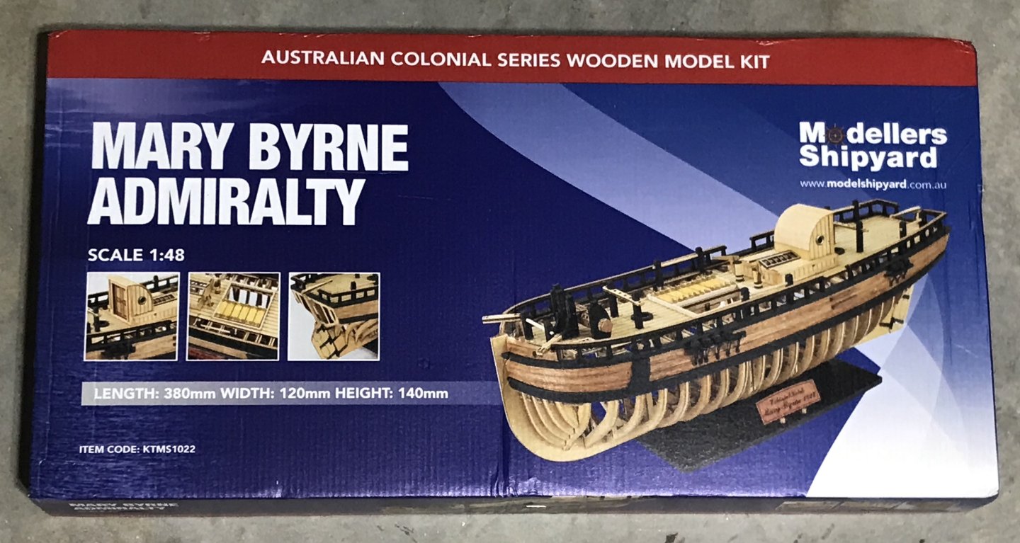
-
USS Constitution by mtbediz - 1:76
mtbediz replied to mtbediz's topic in - Build logs for subjects built 1751 - 1800
Thank you very much for your interest Bruce. Like everyone else on this forum, I'd be happy to help. Please don't hesitate to ask whenever you need. -
 I tend to agree with druxey but your latest attempt looks solid Marc. I used thread to strop my dead eyes on the Vasa, I used thinned down PVA with paint and while still wet I rolled it out on a flat surface with a metal straight edge but a paint stick would work just as well, this seems to hold the fibers in check and the end result looks good. Michael D.
 -
 Hopping on board this build log. The first model you build is fun and exciting. And it can be a bit scary. But don't fret. You'll do fine. Take your time and enjoy the experience. You will learn a lot during the process. And, if you've read a lot of builds, in just about every one are "I'm not entirely pleased with..." or "if I were to do this again, I do it...." comments. However, at the end of the build you will also see, 'I am pleased with what I built" type comments, too. The latter statement should be the goal. The former shows the learning process. Don't forget, you have a bunch of people here willing to help out with that learning process. Just ask. Good luck and have fun.
 -
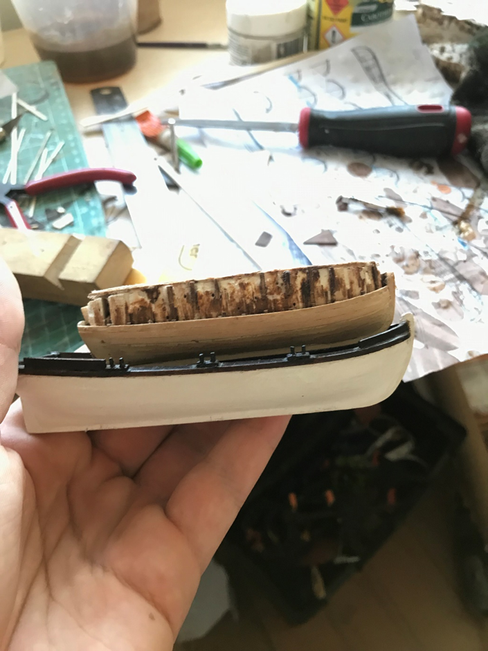
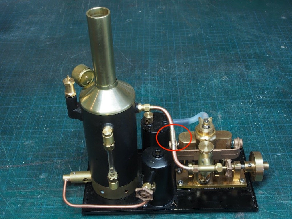
 It's been a while since my last update but work has progressed, albeit very slowly. I changed my mind (again) about removing the excess ABS, mainly because it would have been impossible to hold the internal stringer/gunwhale(?) in place with it sill there. So I went ahead and removed the excess ABS, and then positioned the stringer/gunwhale and the internal (fake) ribs. I also drilled out the hole for the propellor shaft and cut the access hole for the rudder support strip that extends from the keel. I decided to replace the kit-provided stuffing tube and propellor shaft with some after-market parts from Float-a-Boat in Melbourne (following the lead of Wayne (@a49kid)). At the same time, I ordered some universal joints and a brass propellor to replace the kit-provided plastic one. Unfortunately, with the additional thickness added by planking the entire hull, a propellor of the same size (40mm) will not fit. I’m still deciding as to the exact size that I will use, but it will be either 35mm or, more likely, 30mm. The picture below shows the internal ribs in place along with the stuffing tube and propellor shaft temporarily positioned. I may well need to adjust the length of the stuffing tube/propellor shaft once I’ve got the steam plant sorted. Before proceeding further with the hull, I needed to sort out the steam plant and its positioning/securing in the hull. That meant doing a trial run of the plant. I bought this plant from Miniature Steam Models (MSM) over 18 months ago and had not done any final assembly and testing to date. It comes almost fully assembled, requiring only the attachment of the steam line (from boiler to engine) and the gas line from gas tank to boiler. Unfortunately, for some reason the steam line was a few mm too short to be connected. This was very surprising as MSM have a very good reputation for quality. Anyway, I enlisted the assistance of a fellow Canberra modeler who is something of a guru on all things steam engines. He advised cutting the existing pipe and inserting a short joining section to make up the length required. He also very kindly machined up the required part and silver soldered it in place for me. The result can be seen in the picture below, highlighted by the red circle. We did a short test that proved the join was secure and together we are now conducting some “set-to-work” trials. There are still a few other issues to deal with before proceeding with the hull, but I hope to resolve those in the next few days.
- 38 replies
-
- 4
-
-
-
- live steam
- radio
- (and 2 more)
-
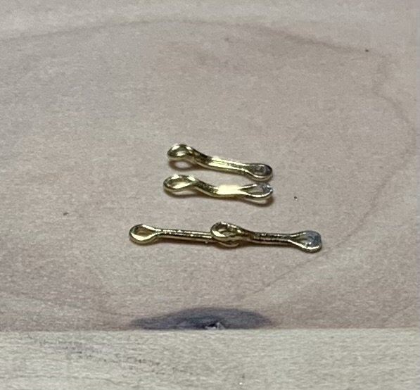
 Late to the party; the soldering should be on the straight part of the loop, not the end. Failure rate should be much lower.
 -
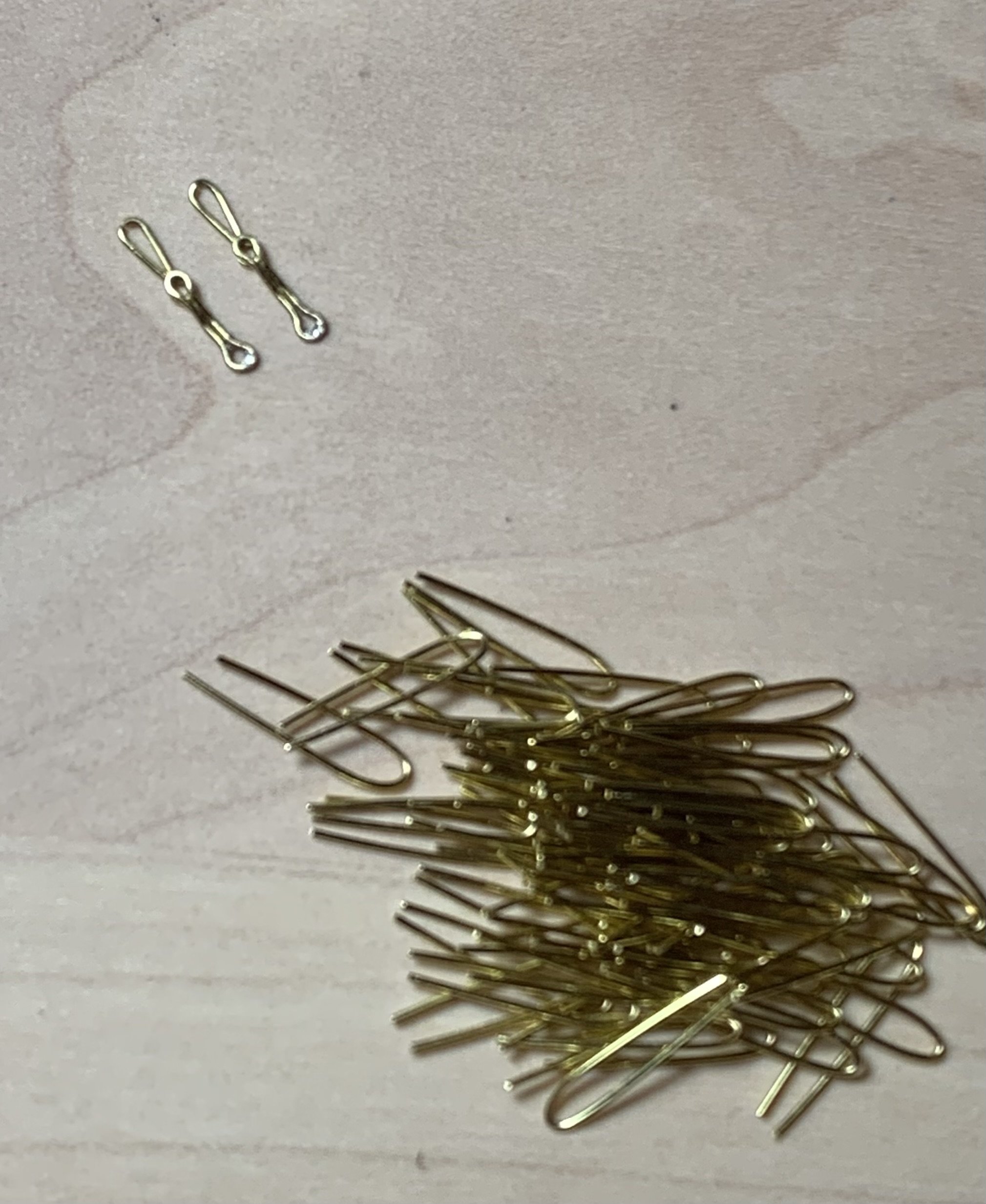
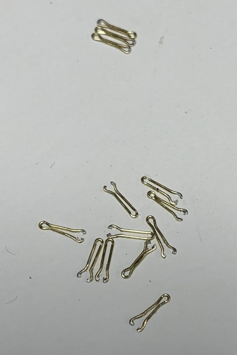
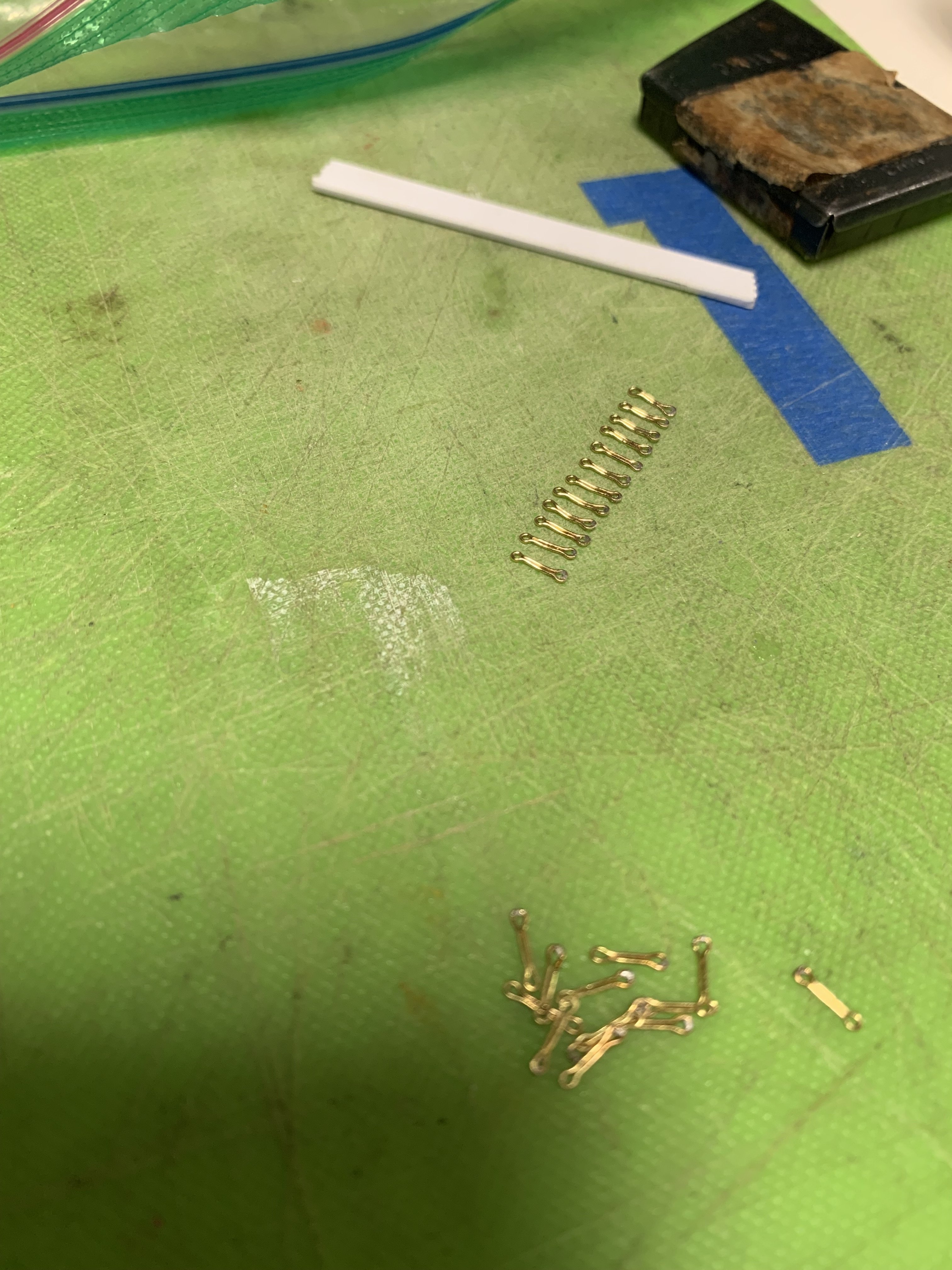
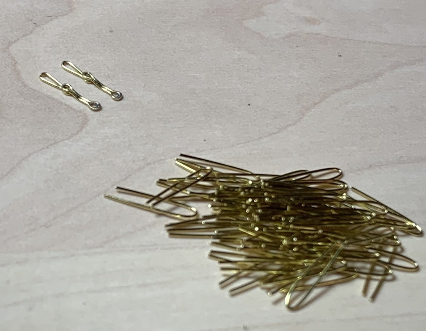
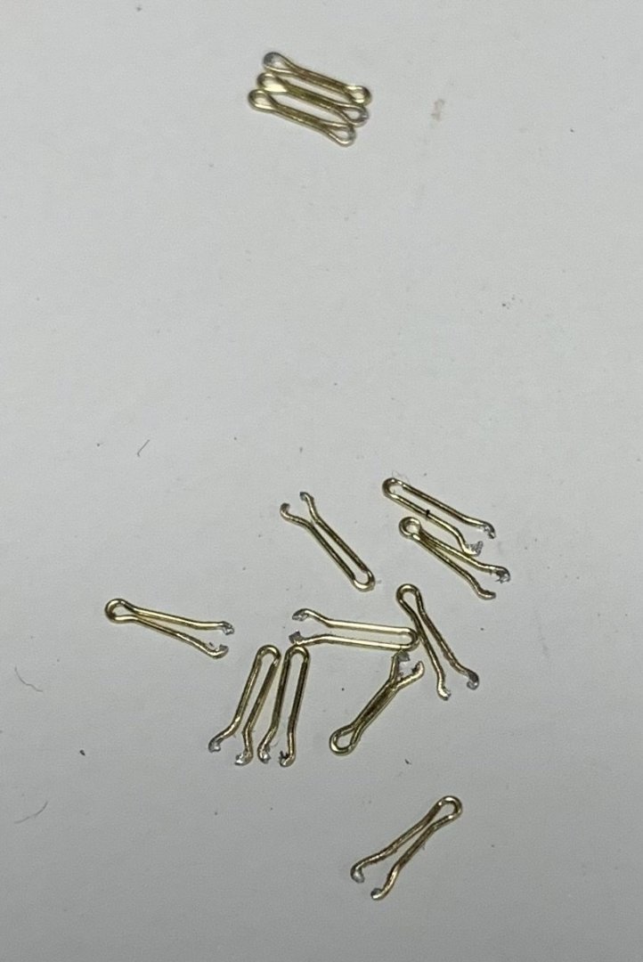
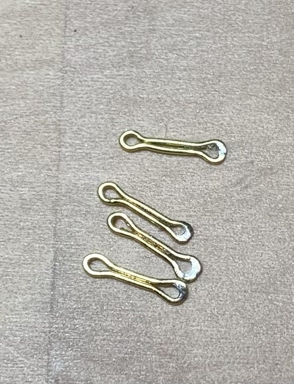
 I can’t escape the fact that I continue to fail at this chain-making exercise. As the old maxim goes, though, every failure is one step closer to success. I’ve now thrown away two whole batches of chain preventer plates. While I was quite right to follow Andre Kudin’s example, for the process of their manufacture, I eventually discovered that that process is not entirely transferable from 1:48 to 1:96 scale. After forming his basic links, Andre solders them closed at one end, and then places the closed link back onto the two pins so that he can crimp an eye on each end with his round pliers. Well, the 28 gauge brass wire I’m using does not provide enough surface area for a strong enough bond to survive the crimping. My success to failure ratio was pretty poor: So, my lesson from that exercise was that I needed to do the crimping before soldering one end closed: These soldered loops will be the lowest end of the chains, bolted into the wales. That way, I could induce a series of bends into the upper half of each preventer plate, so that they could overlay the next small link: Above I’m just using another preventer plate to check that the bends I’m making are sufficient. So, I spent a good chunk of time cleaning up the solder and inducing bends into the remainder of the preventer plates. The solder joint will be re-enforced with the CA glue that fixes the pin-bolt in place: With that out of the way, I could make a new, slightly closer-spaced pin jig for the next small link, which is only crimped on one end, where it seats beneath the preventer plate. Now that I have a process that I know will work, and now that I’ve had all of this practice, these next links should go fairly quickly: I have a lot of these to make, solder and bend - about 70 to ensure I can use the best. This has all been a colossal PITA, but it was really important to me that all of this look very clean and uniformly shaped. In the process, I have acquired some very valuable metal skills that will only enhance this and future projects. That said, I am going to experiment with using black nylon thread of an appropriate diameter to connect the deadeye strop loops to the small links. This would essentially be a variation on the way that the stock kit represents these links, but I will do individual chain loops that draw tight with some form of slip-knot that I can pull up and hide behind the deadeye strop. Andre had a great method for producing these variances, but it is all just that much more tedious in the smaller scale. The advantages of doing this are several. So long as there is not a jarring difference in appearance between the black thread and the blackened metal, it will save me tremendous amounts of time. It also simplifies the difficulty of accurately measuring and keeping track of a series of increasingly longer links as the shroud angle increases from fore to aft. Lastly, it greatly simplifies the placement of the deadeyes because I can add the retaining strip, in advance, and it also makes it much easier to locate and properly secure the bottom two links. Hopefully, that will work out. Well, I keep saying that I’m going to get back in the swing of the project, and then I get sucked into coaching another basketball team - now my son’s Spring rec team. Meanwhile, the Rangers and Knicks are just too compelling to ignore this post-season. At least for now, I can see the end of the tunnel for these chains, which is tremendously motivating, and then I can return to the more immediately gratifying work of outfitting and arming the main deck. Thank you all for taking the time to look back in on This Old Build. More to come!
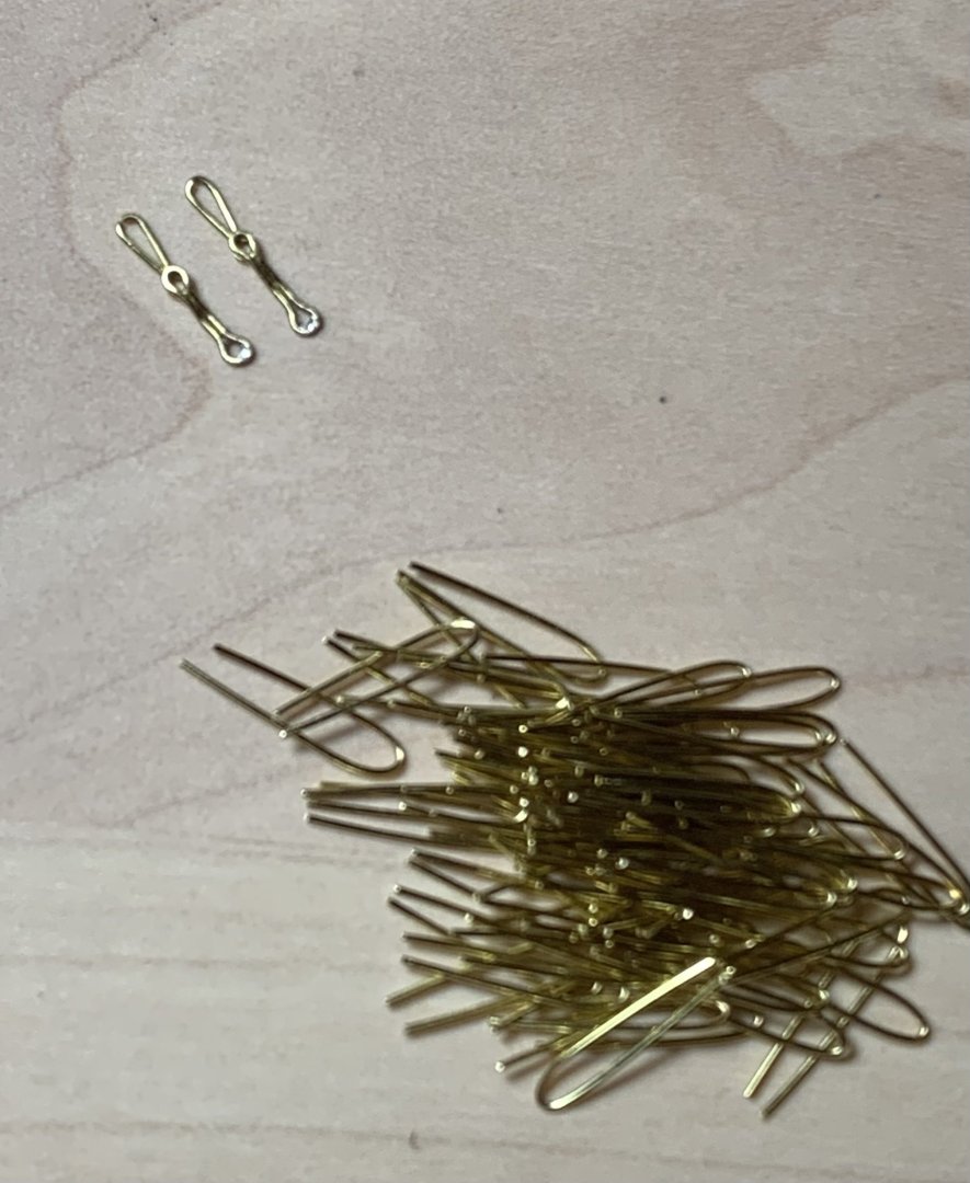

- 2,435 replies
-
- 4
-
-
- heller
- soleil royal
- (and 9 more)
-
 I feel dumb. Can someone point me to the parts for the false keel? Cant seem to find them.
 -
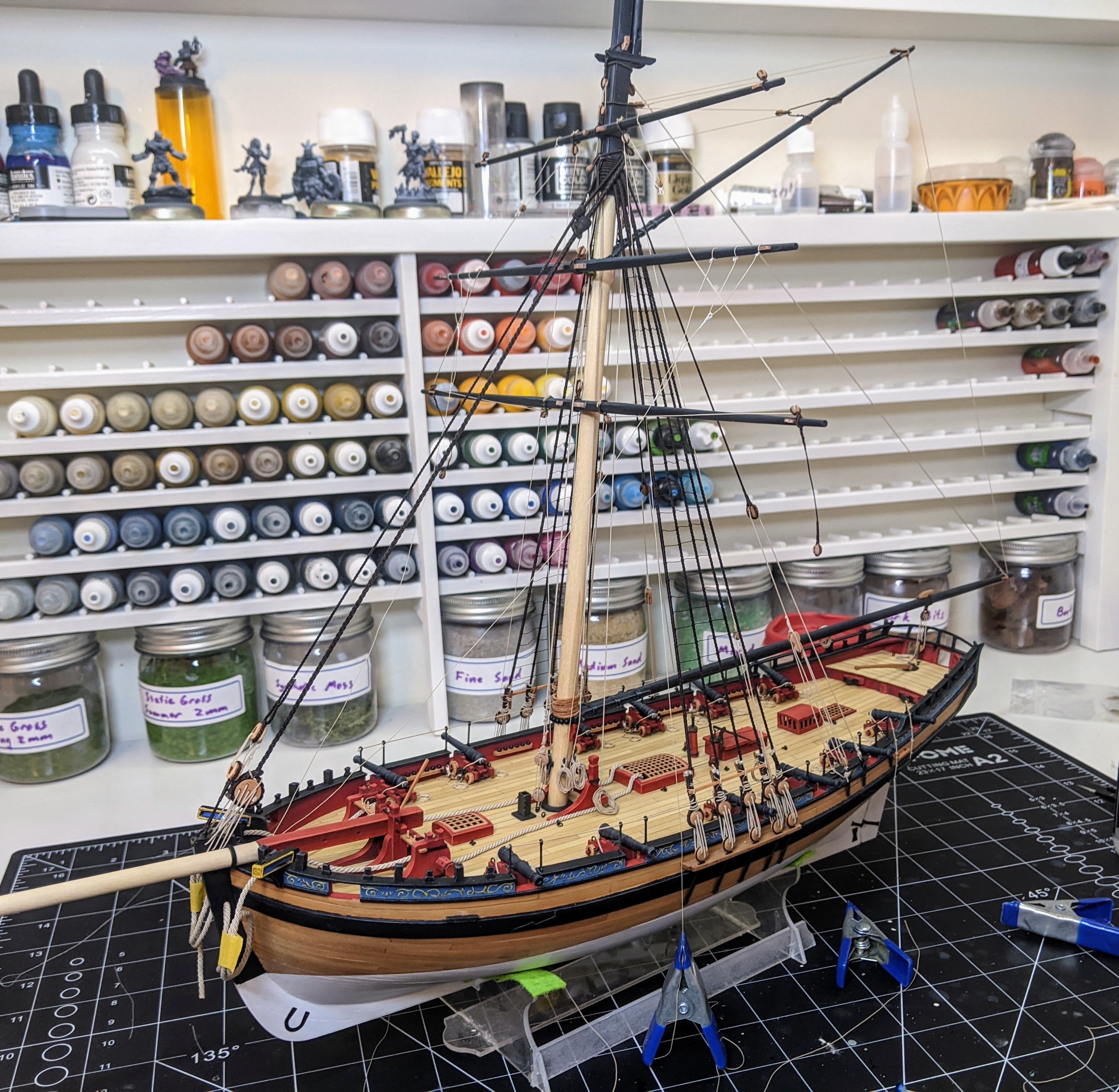
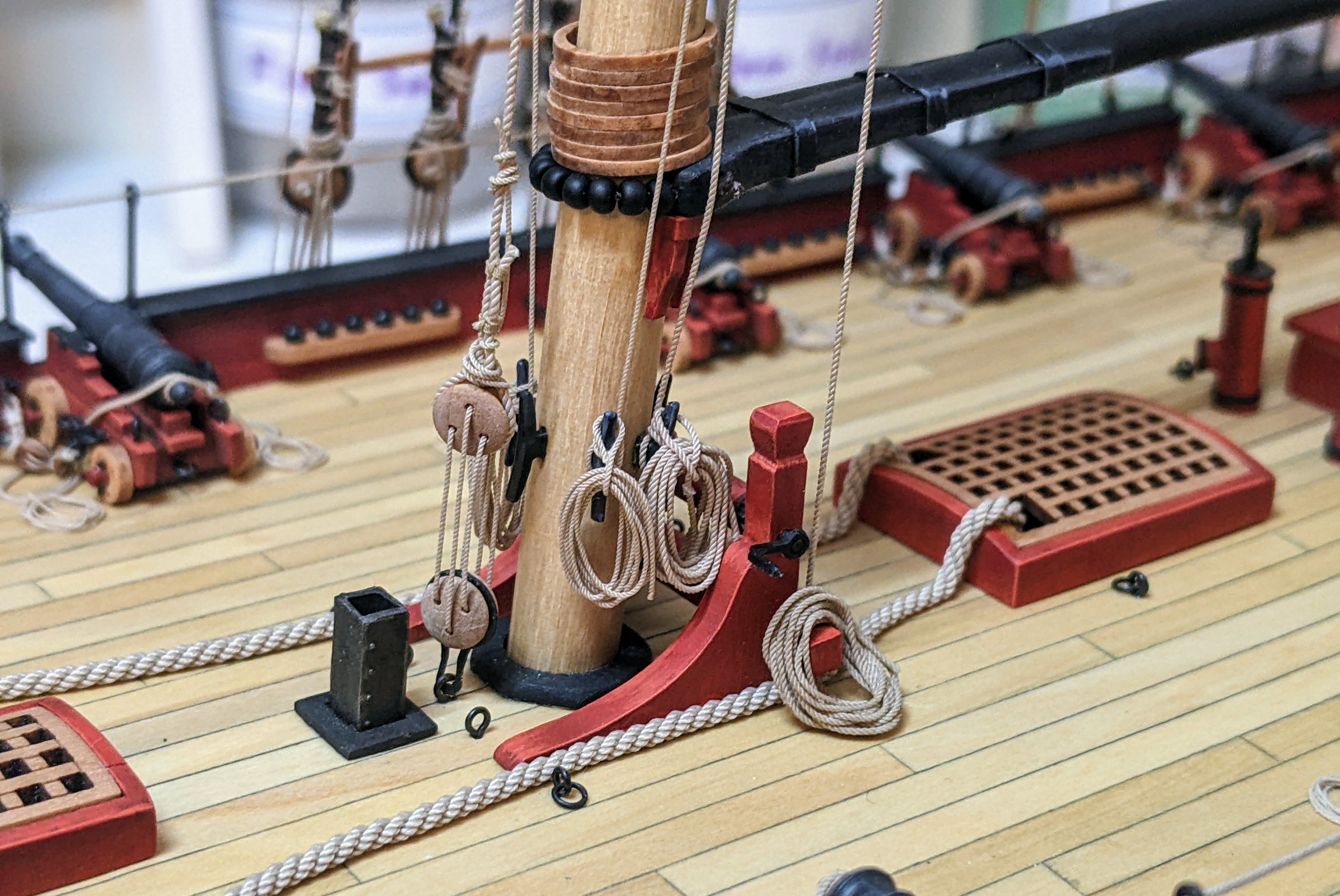
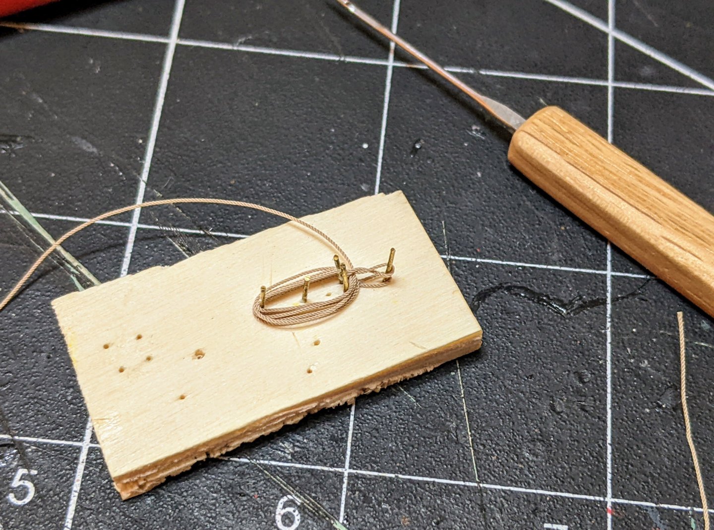
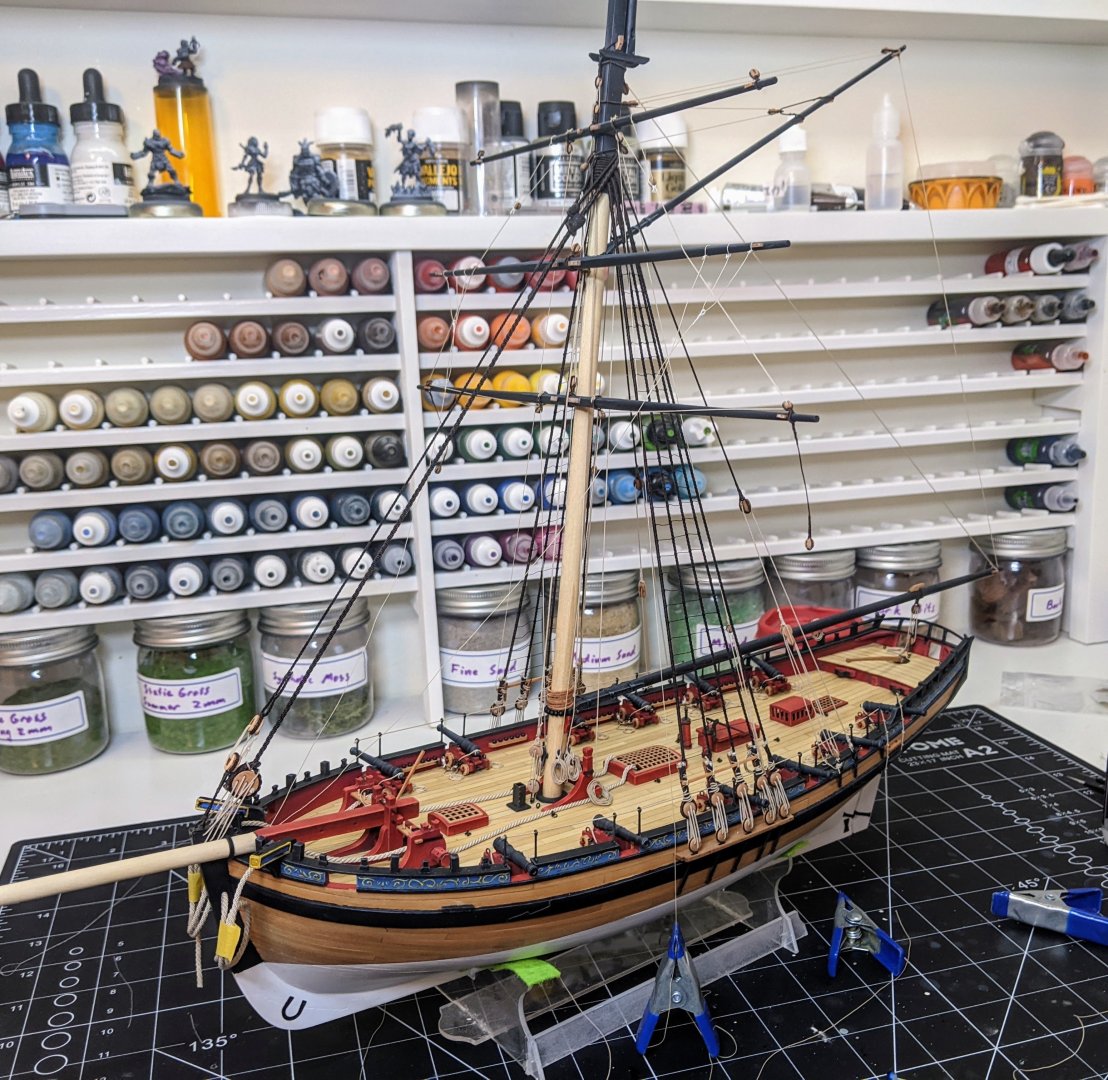
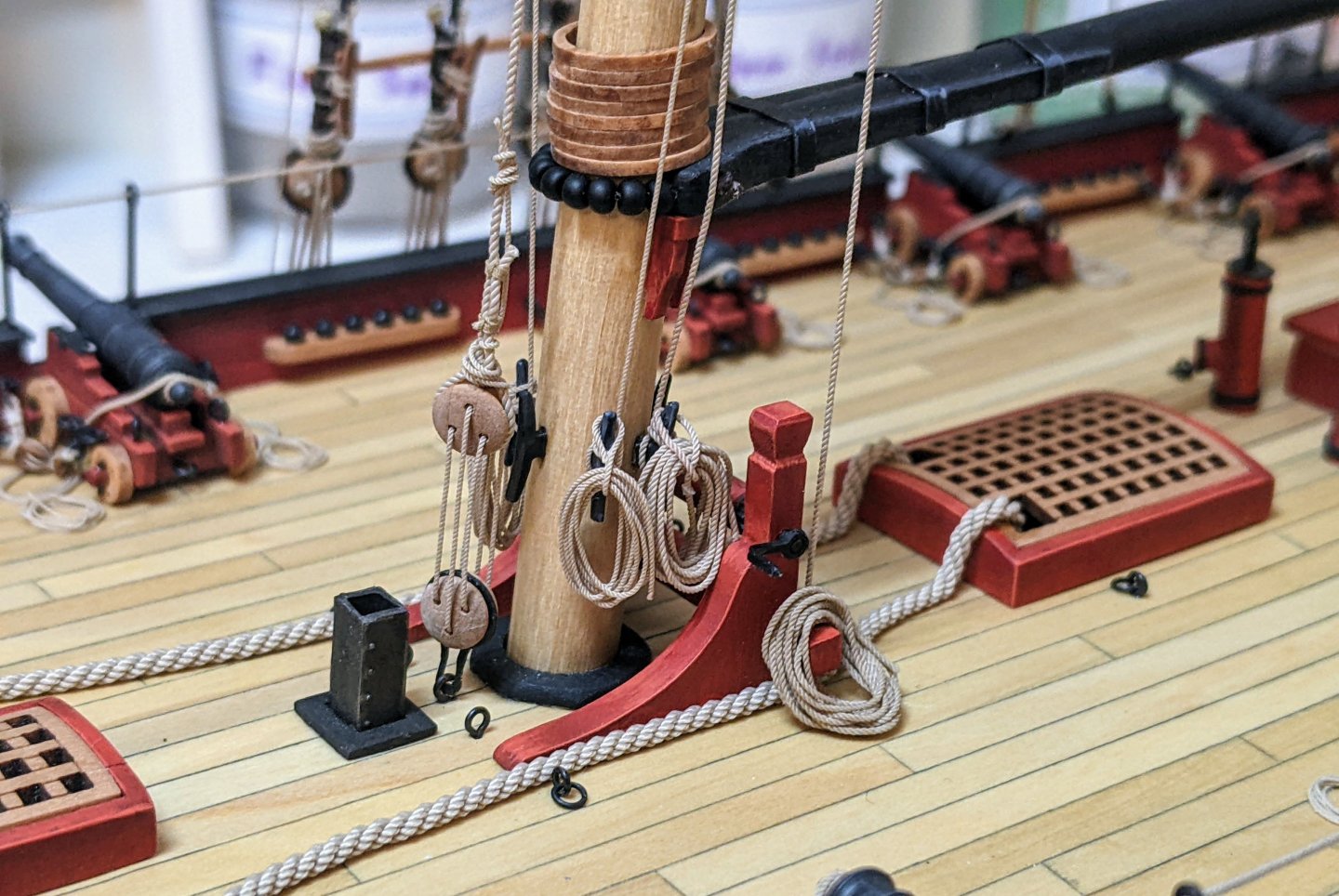
 Log #83: Tying off the Ropes Thank you to everyone for looking in and for the encouragement. I always like this stage of the build as the tying off and making rope coils goes very quickly, and so you get lots of visible progress after a long period of preparing the yard off model. I believe I have shown this before but here is my jig for making the rope coils. The top loop starts out on the pin that in the picture has nothing on it. Then once I have done a few loops I twist it and fold it over. Then I finish the hank by continuing to loop the rope and insert the end into the gap between the two loops for the cleat. Once it is done I use a dab of super glue to fix the loops together and the end of the rope in place and then give it a few blasts with the hair dryer to try and get it to stay in shape. I then slip it onto the cleat and use super glue spots to tack it into place. You can see below I have belayed the topsail lift to the mast cleat on the left and the starboard topsail sheet to the cleat on the right. Then the larboard topsail sheet was belayed to the left cleat in the below picture. The right cleat is holding the previously belayed squaresail yard. I am going to hold off on belaying the clewlines until I get the topgallant sheet lines in place so I can make sure they avoid each other. Below you can see the current state of affairs.
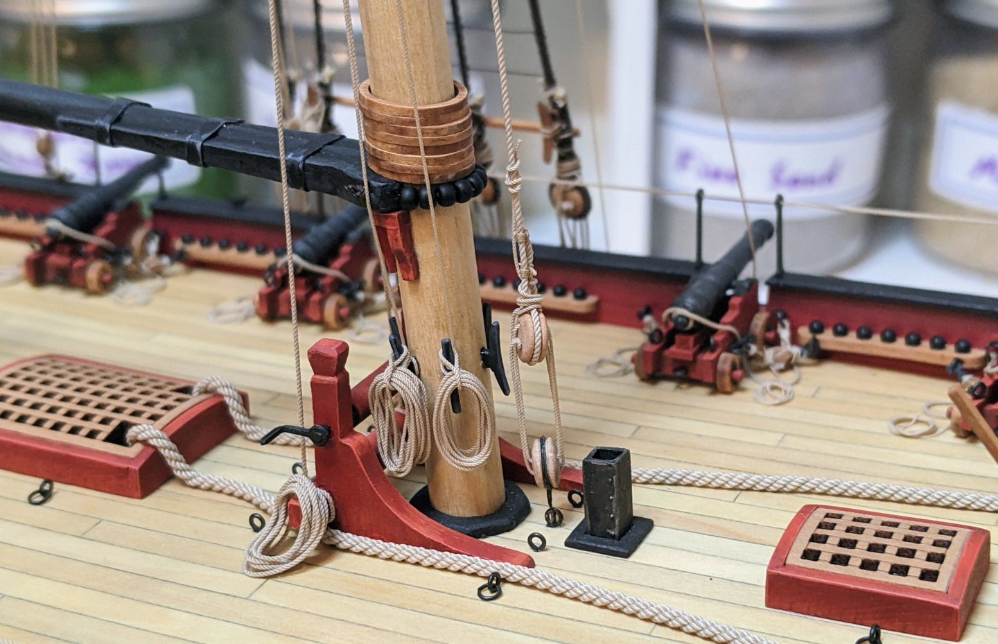
- 479 replies
-
- 7
-
-
-
- vanguard models
- alert
- (and 1 more)
-
 S.Coleman changed their profile photo
 -
 Thanks Eric and Keith for the input, I feel like the decision has been made and adding the mirror it is. Keith, I'll see if I can polish that mirror up a bit. Gary, I hadn't thought about using the engraver to recess the mirror, that is a great idea, I appreciate the tip. It would definitely look better being flush with the top of the base rather than sitting on top. -Brian
 -
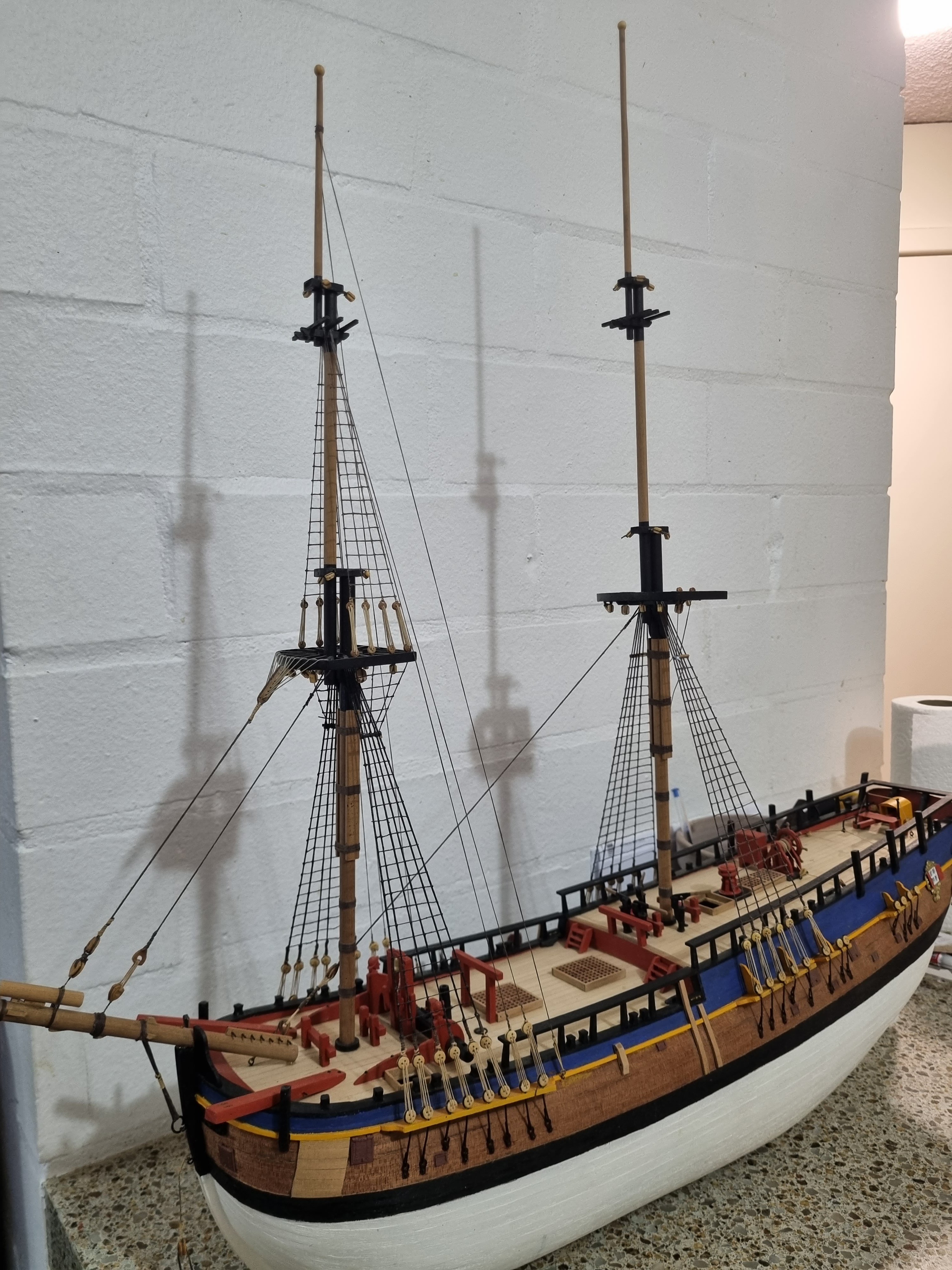
Progress update. Have been working on the main and foremast ratlines and shrouds. Have got to do another crowsfeet set up on the main mast just like the foremast has. I'm happy found motivation again to continue.
-
All keel sections are complete. Moving on to the rabbet. I think I'm not going to try an remove all the laser burn. I just gave it a light sanding to smooth things out nicely. I think most of this will not be visible in the end. Har to get all of it on a picture as its quite long.
-
 And I also bought the fore and aft rigging book by Lennarth Petersson.
- 3 replies
-
- 1
-
-
- vanguard models
- 1:64
- (and 1 more)
-
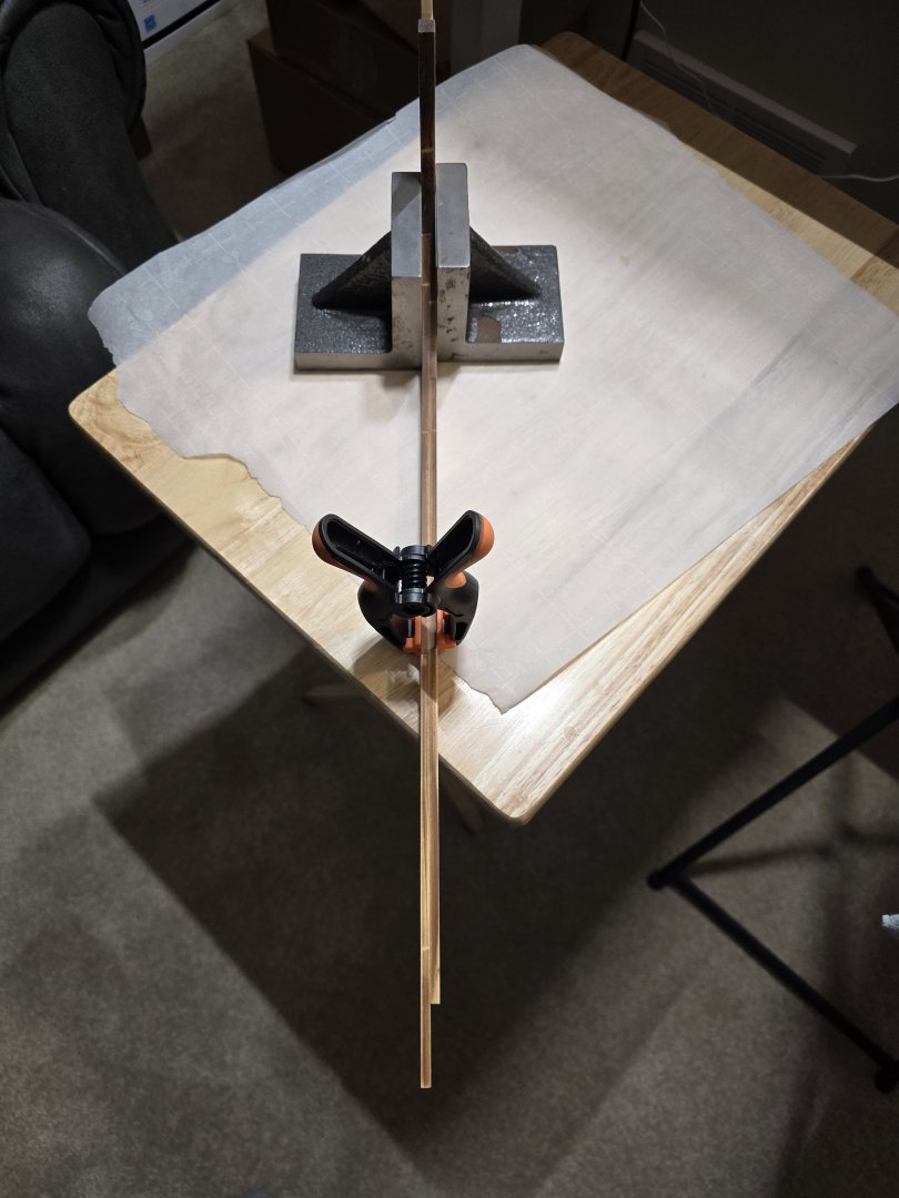
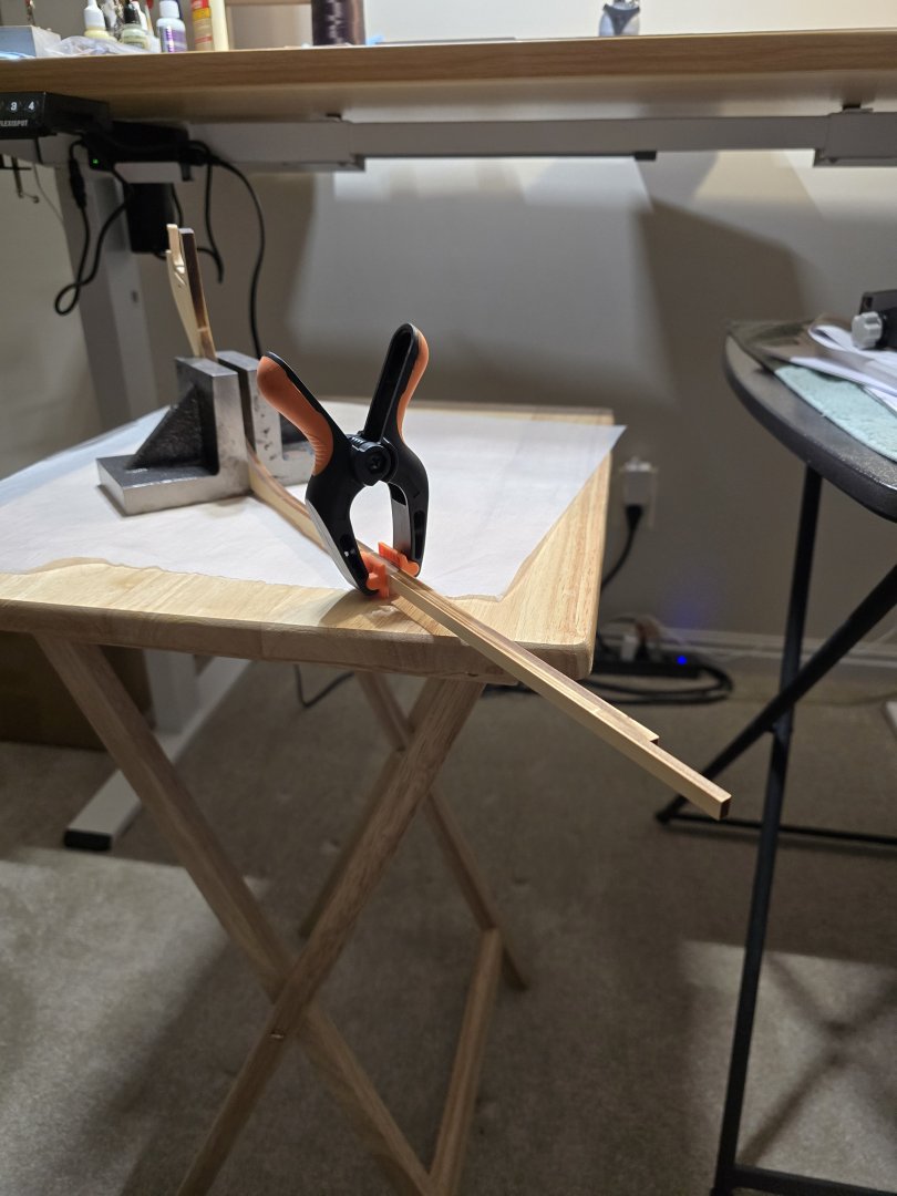
 Main mast is shaped:
-
Yes I would, even though I want it to be accurate, I’m going to focus more on making a good looking build. I don’t mean compromise accuracy, obviously I’ll try my best to have both worlds.
- 3 replies
-
- 1
-
-
- vanguard models
- 1:64
- (and 1 more)
-
 Well done Chuck. Stunning model of speedwell you’ve created.
- 793 replies
-
- 2
-
-
- speedwell
- syren speedwell
- (and 1 more)
-
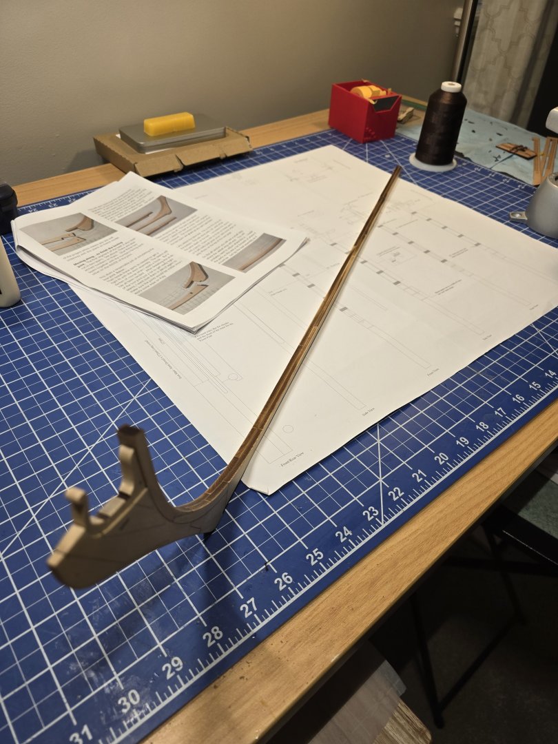
 This is the newly designed false keel, based on the revised drawings of the profile view of the cutter.