thibaultron
-
Posts
2,634 -
Joined
-
Last visited
Content Type
Profiles
Forums
Gallery
Events
Everything posted by thibaultron
-

"Sailing Memory" by thibaultron - Book Size Diorama
thibaultron replied to thibaultron's topic in Non-ship/categorised builds
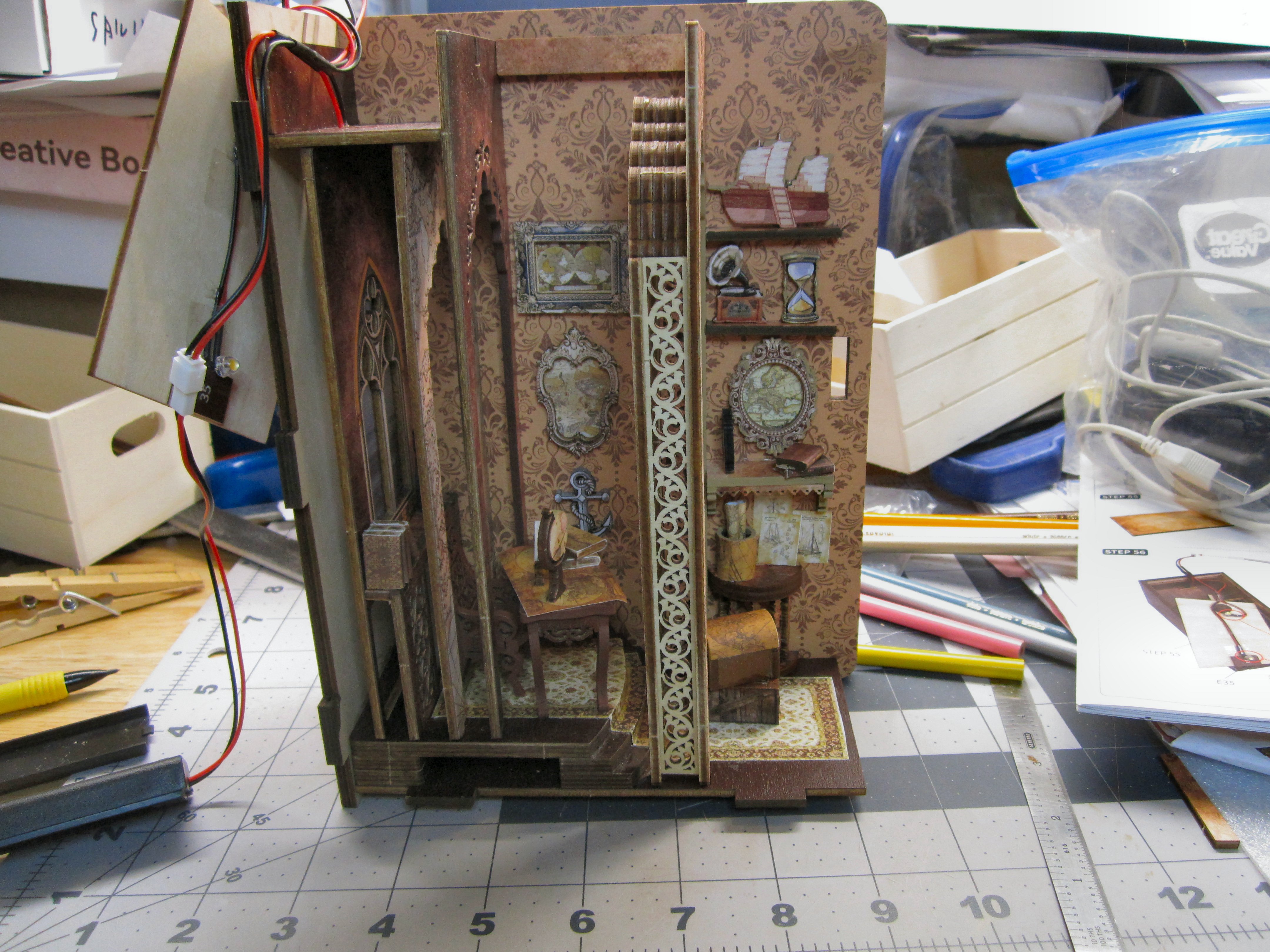
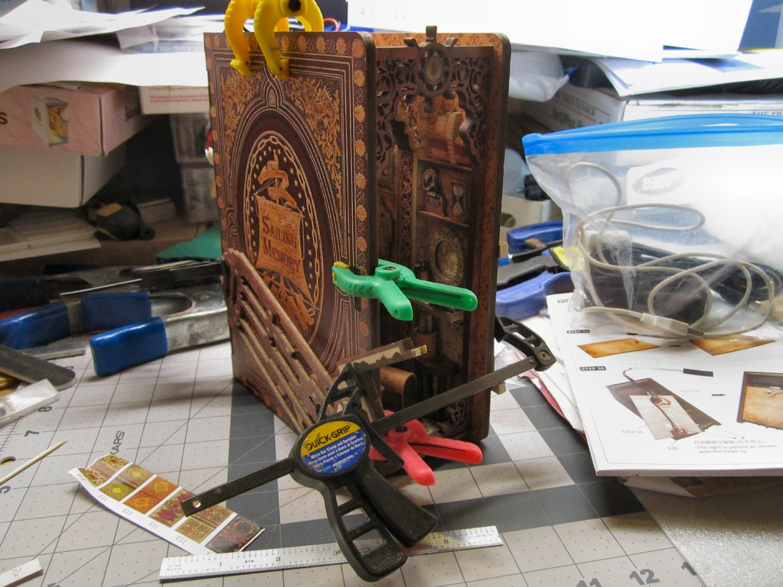
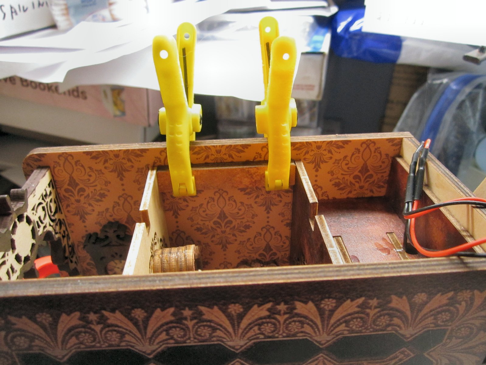
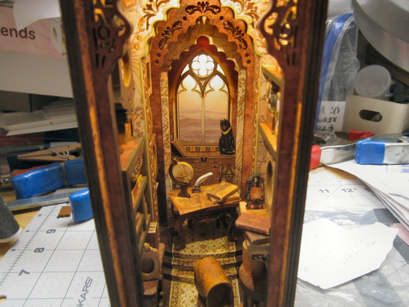
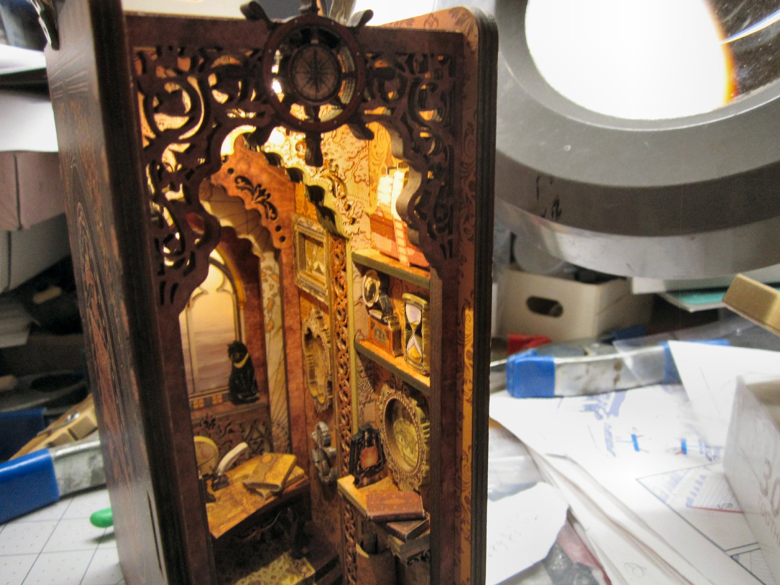
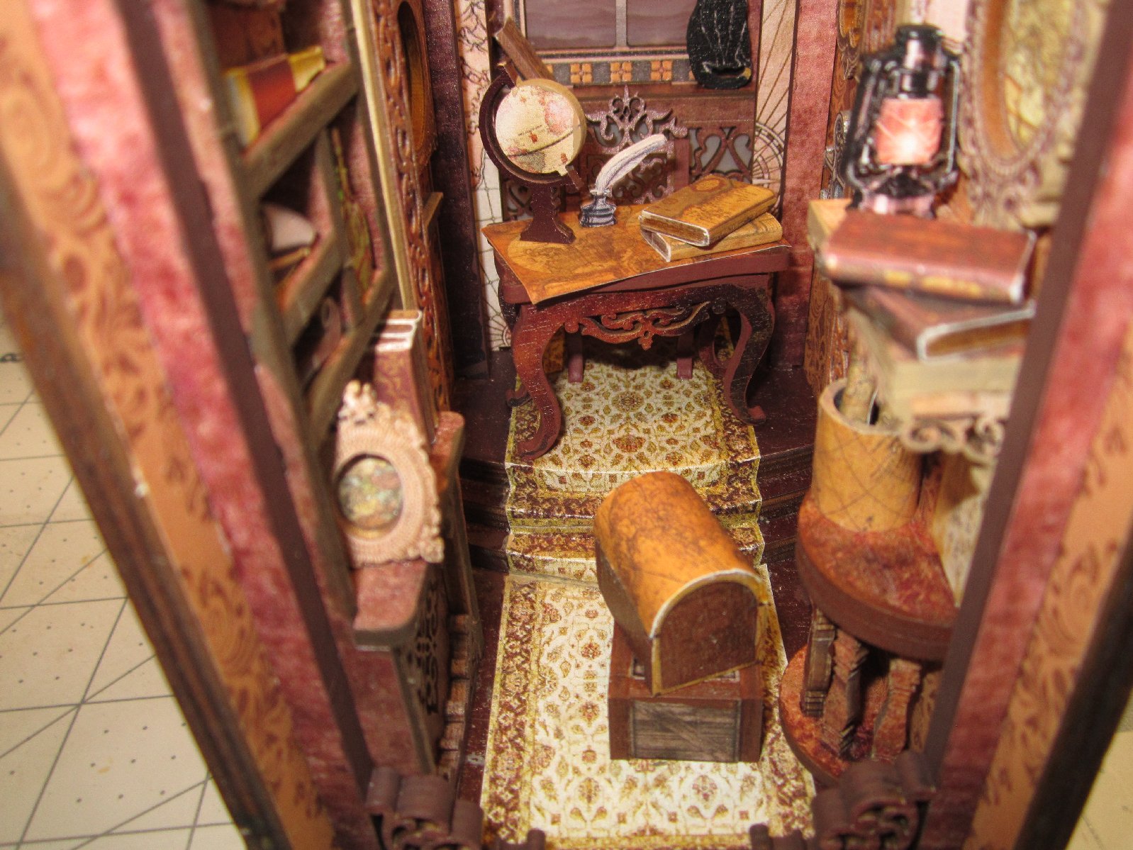
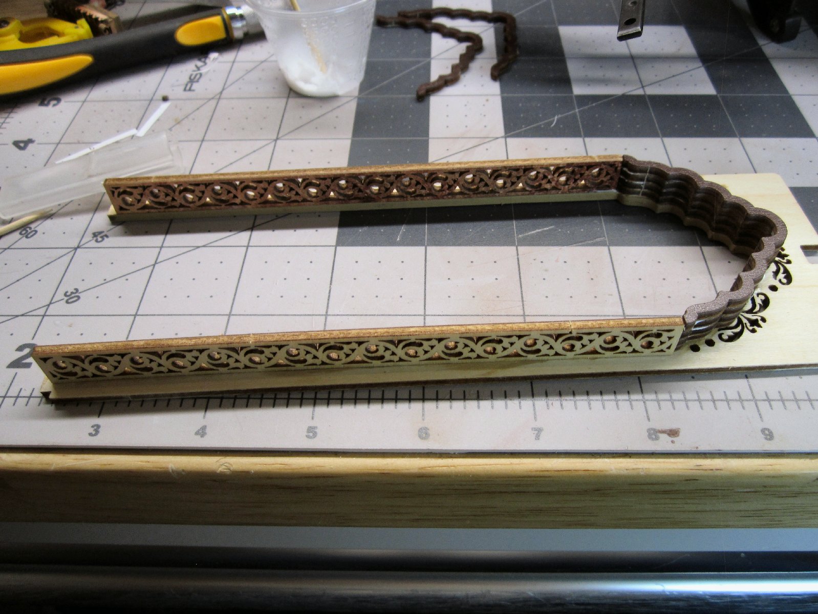
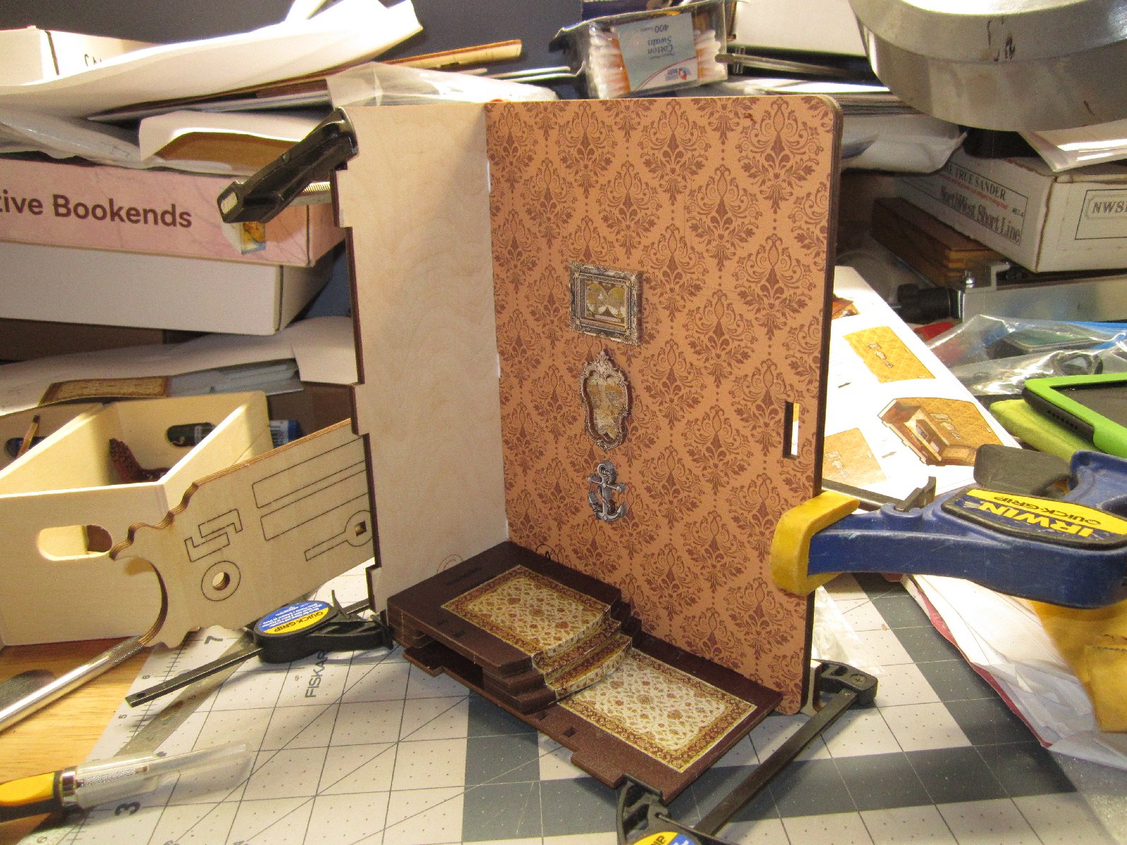
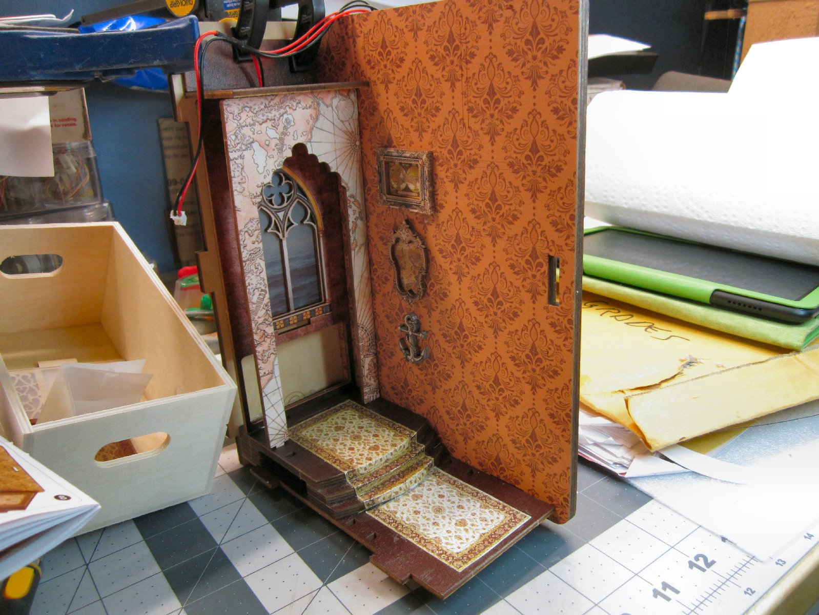
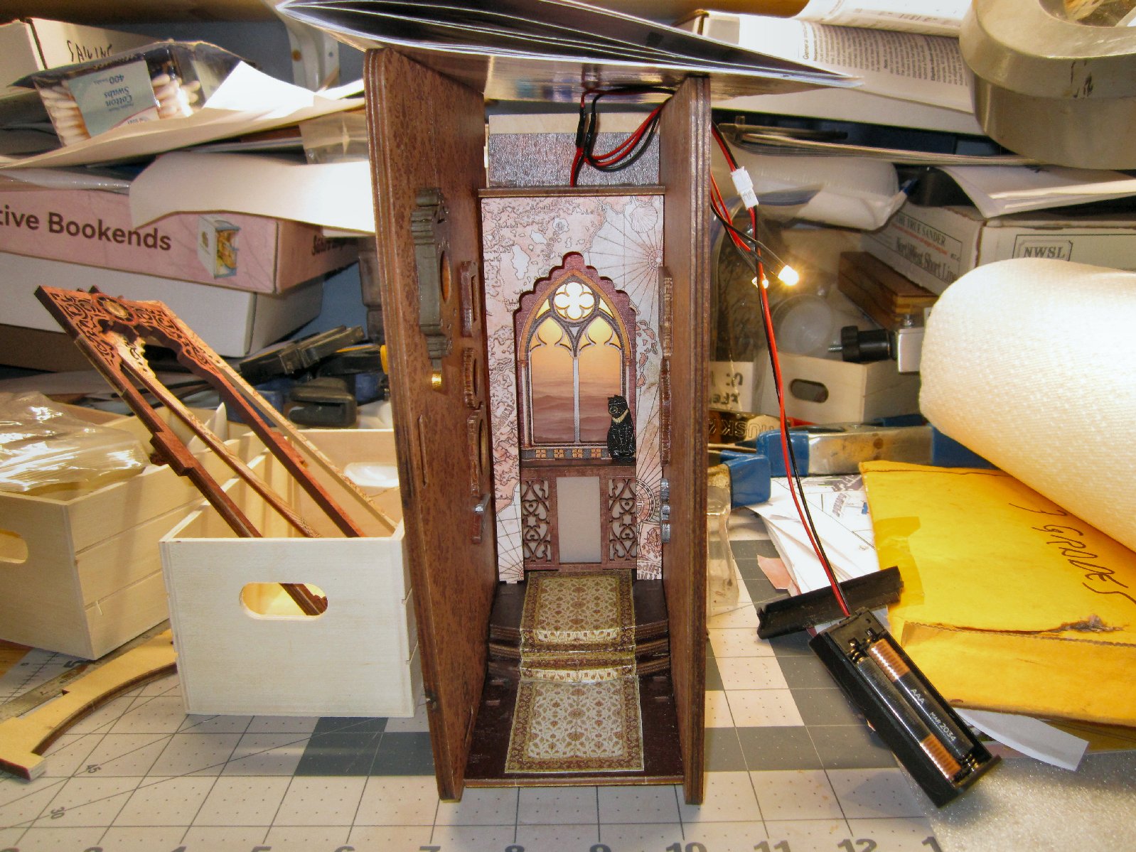
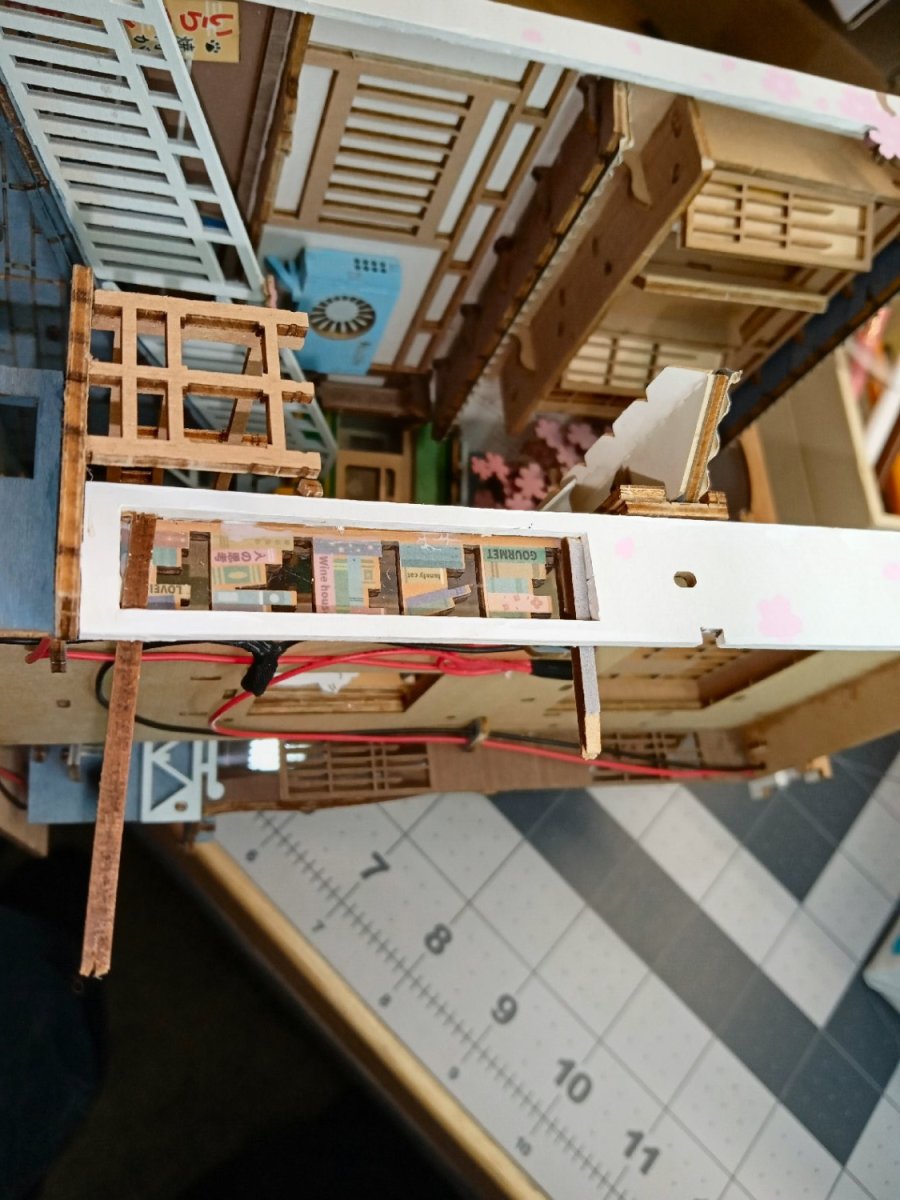
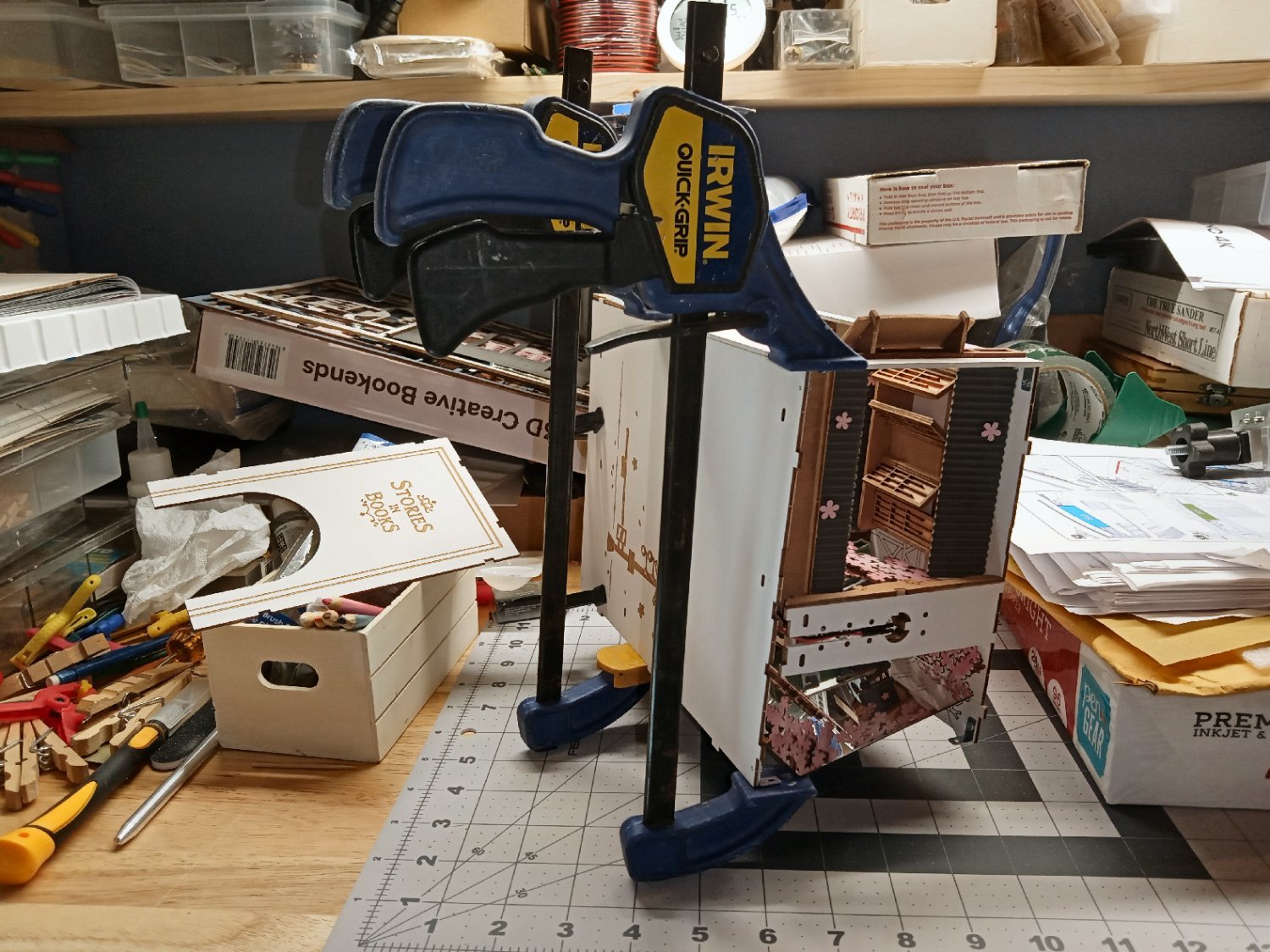
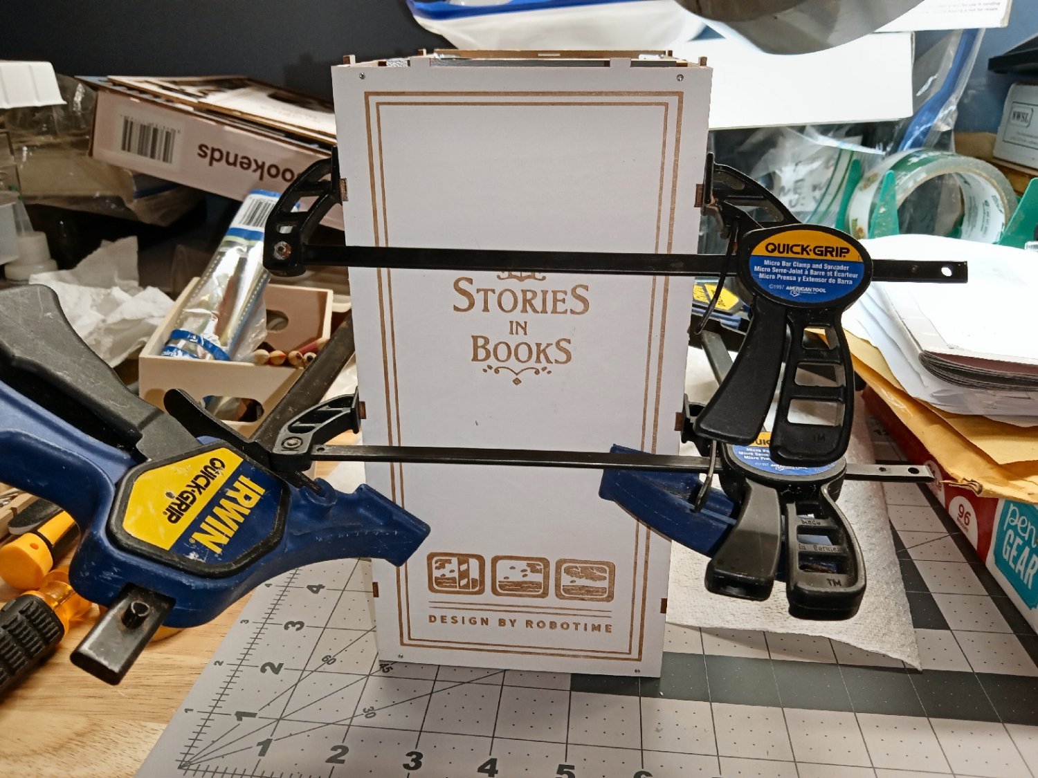
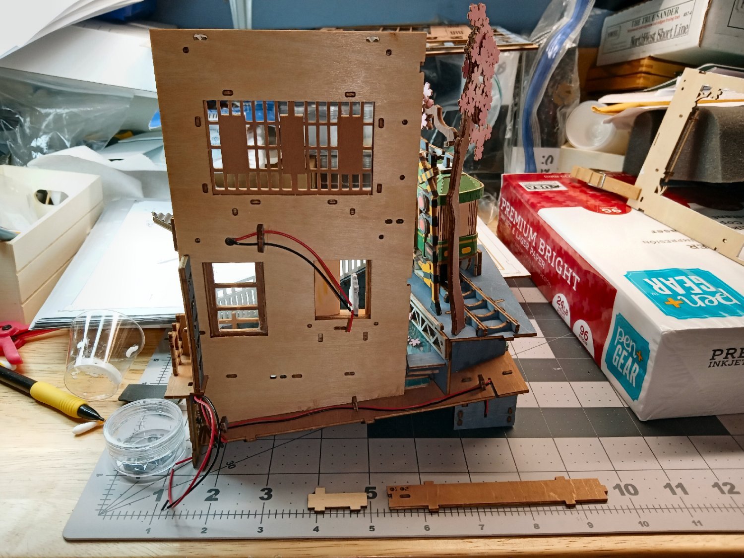
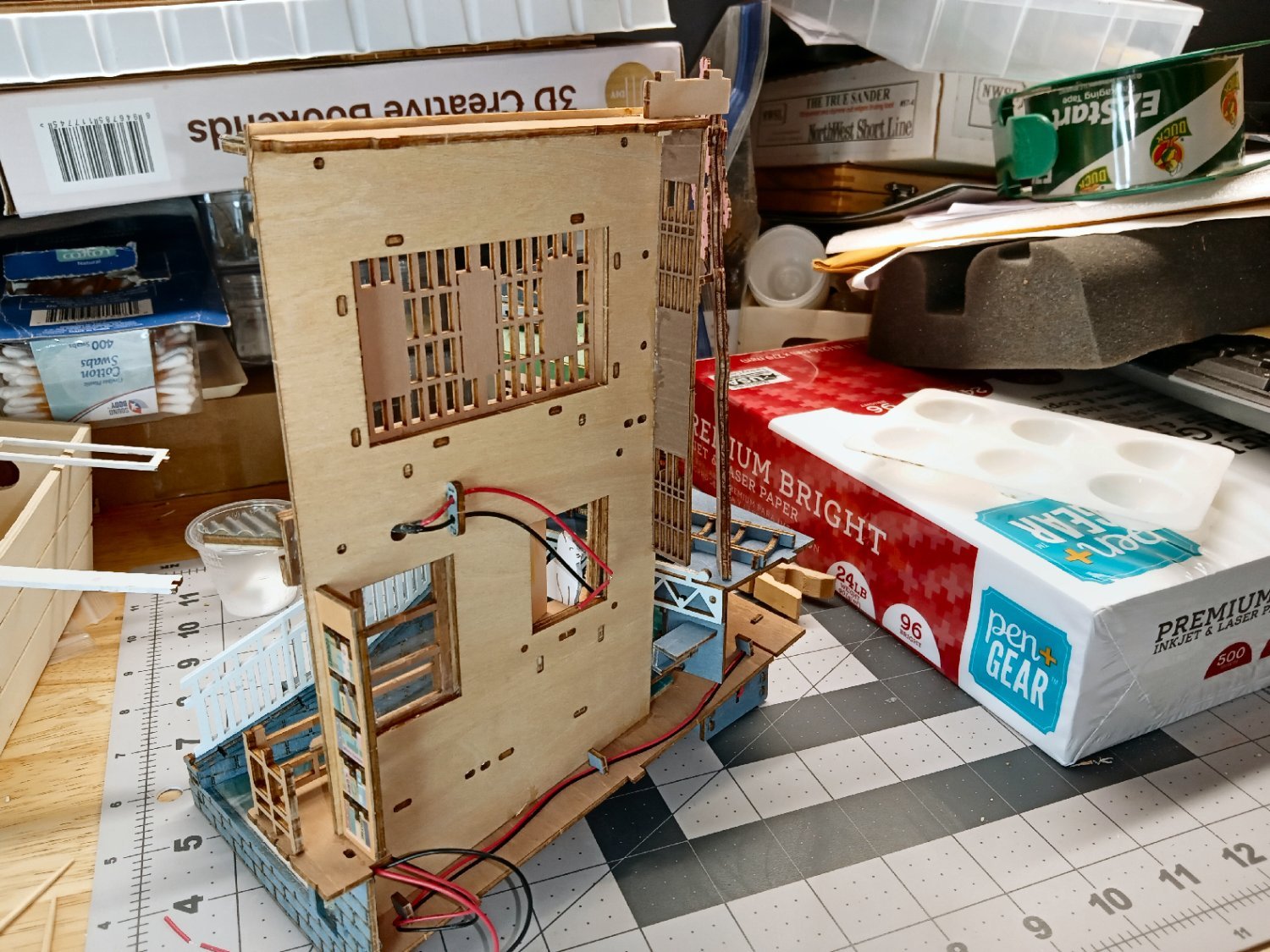
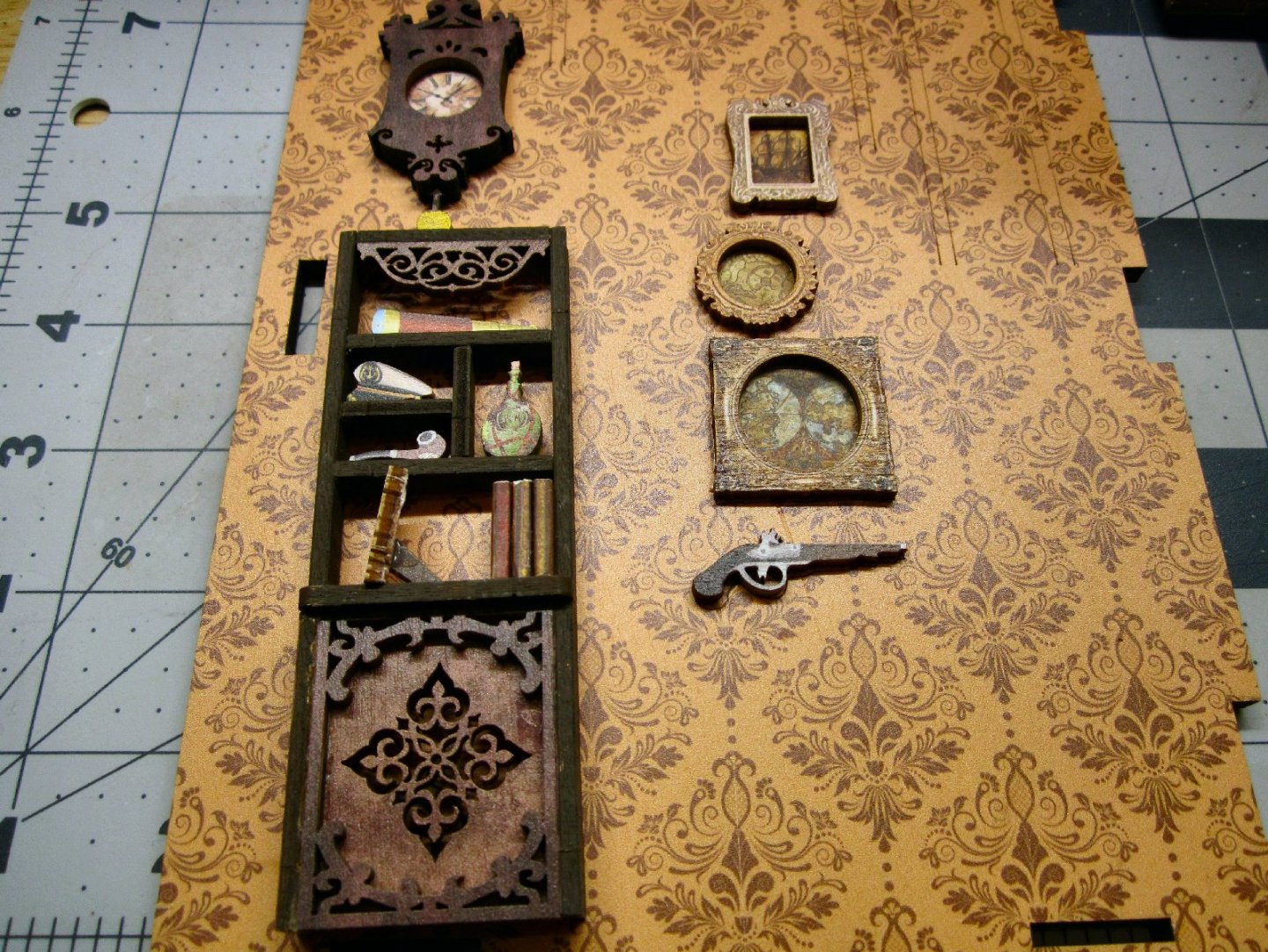
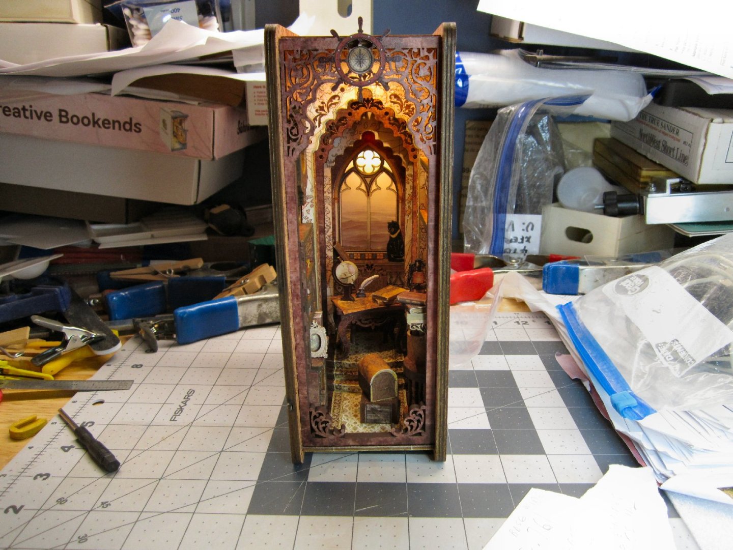
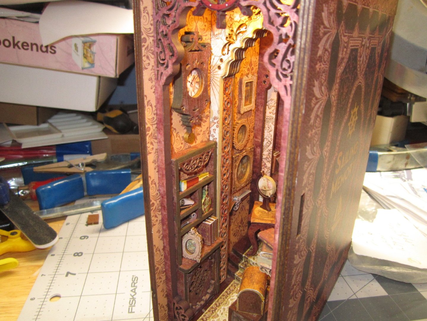
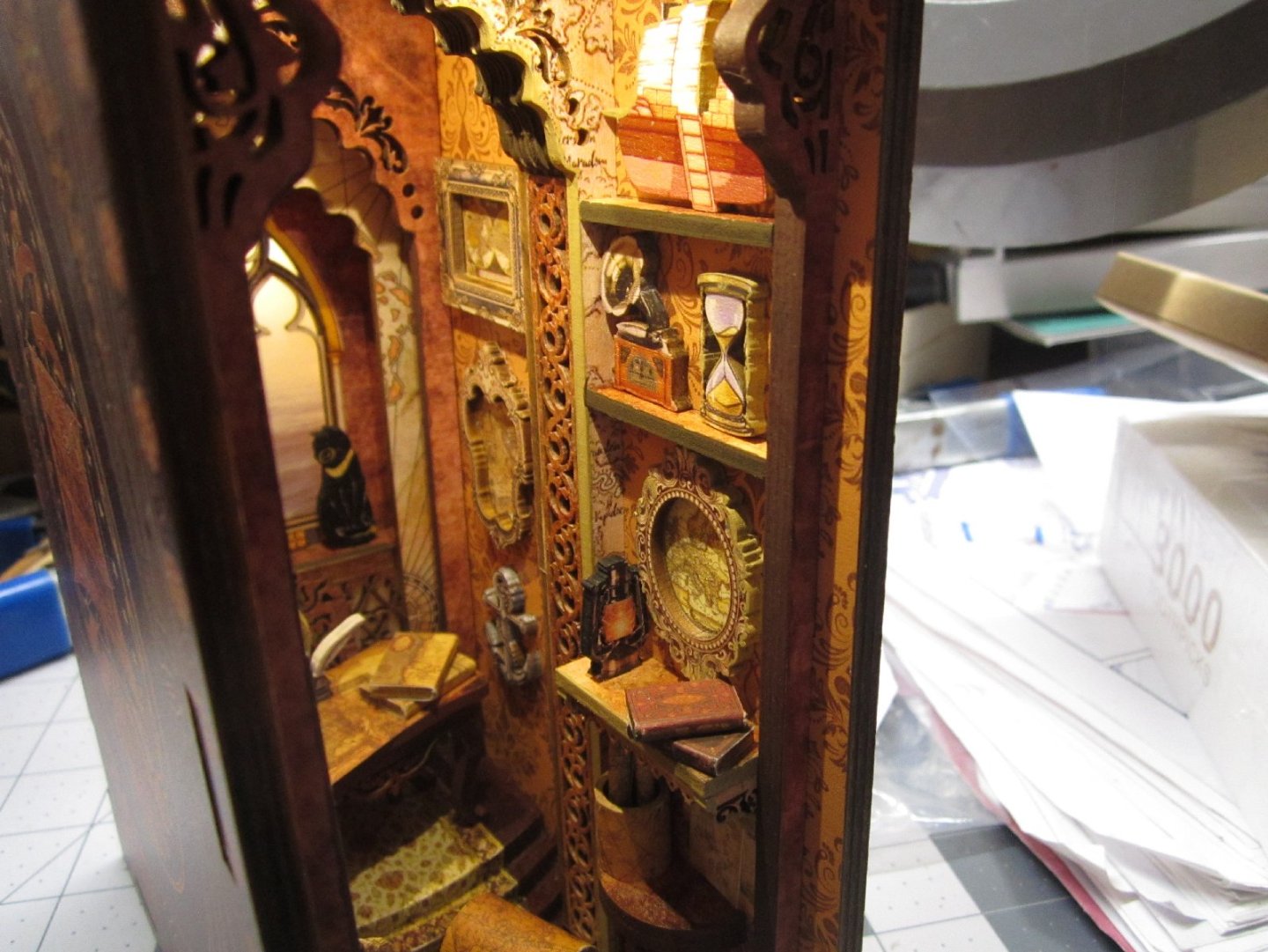
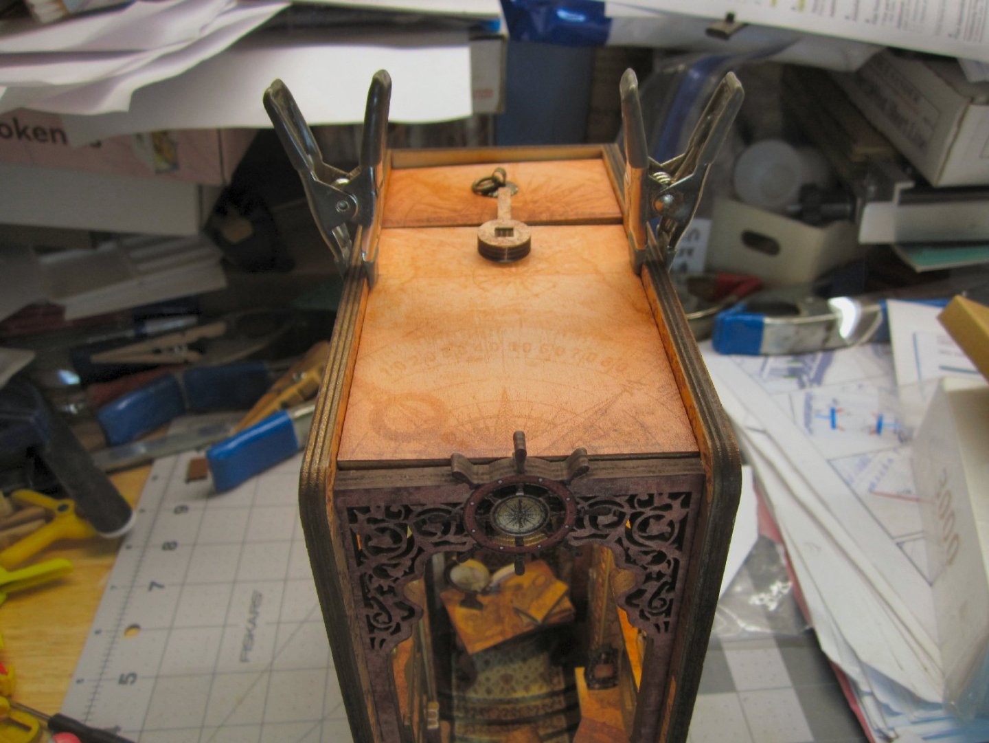
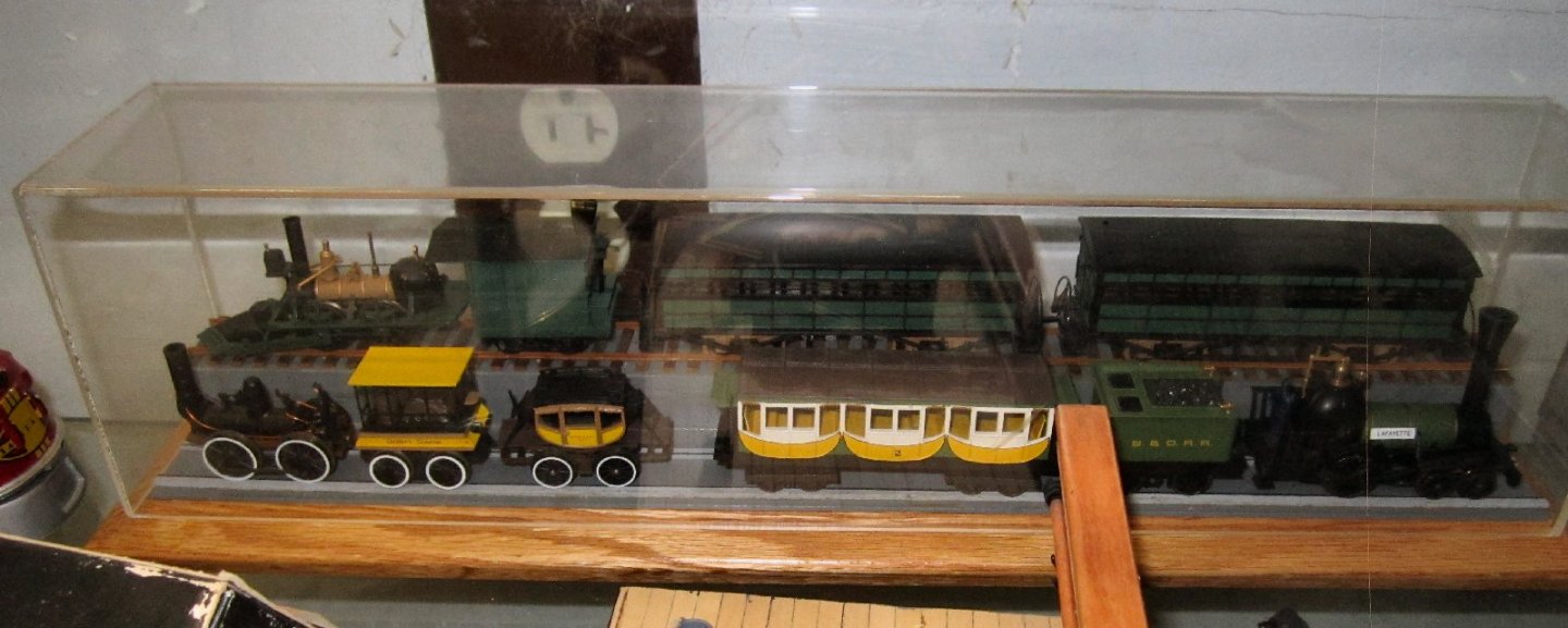
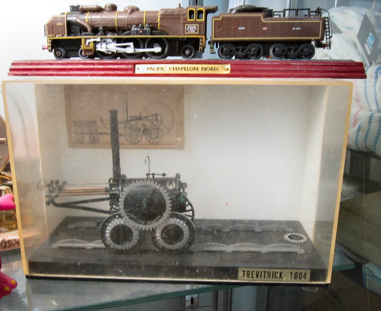
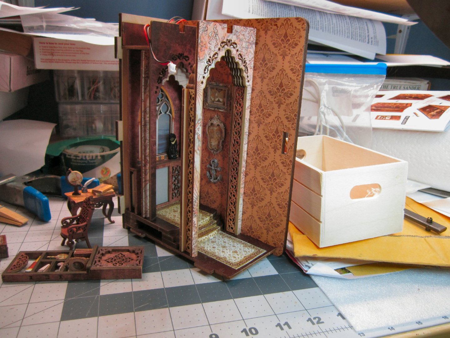
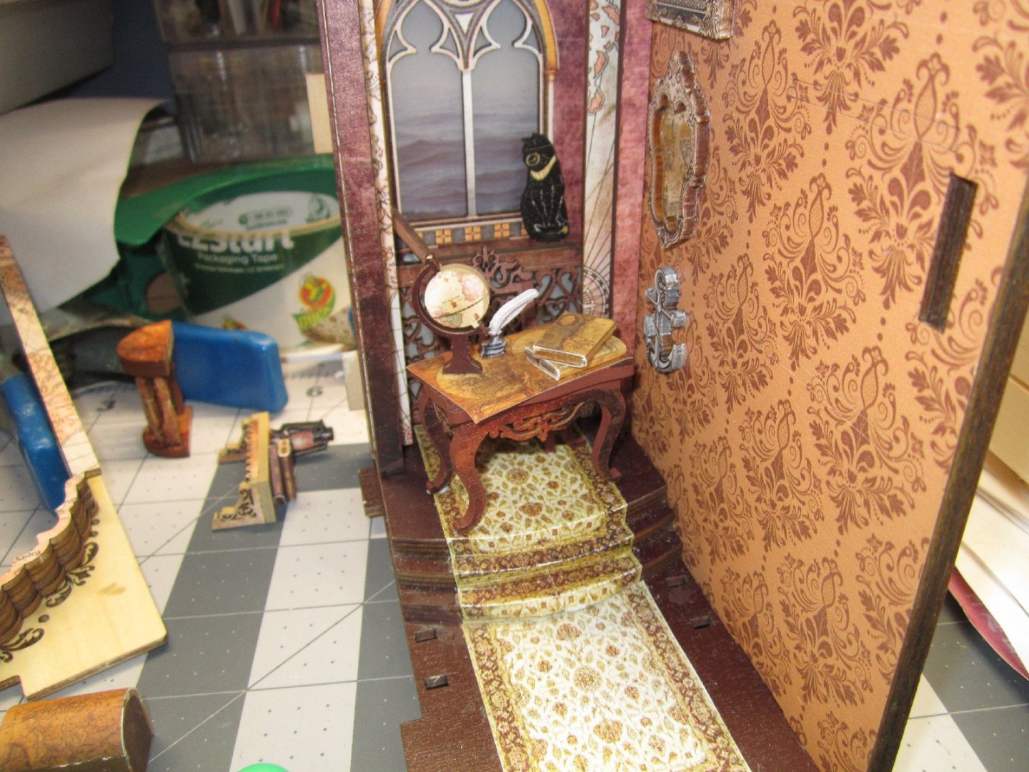
Sailing Memories Part 007 This is the completed right-hand wall of the model. The shelves have been added, and populated. The chest and crate are glued to the floor, and the table with the map holder installed. The last items are three drawings tacked to the wall over the table. You can also see the books added to the cabinet at the back of the display. This is the left-hand wall, before installation. Unlike I thought, the clock is indeed at the forefront of the diorama. I’m glad I took a little extra effort in painting it. The shelving unit is not glued in yet, I set it in the approximate location it will go. I glued it in after this wall was glued on. It fit tightly between the front panel and the foremost arch. I installed the front plate and left wall, clamping it while the glue set. This wall was even more warped than the other, and while all the lefthand sides of the arches were pulled down tight to the floor, the whole unit is slightly racked and the base is a bit wobblily. I may in the future use a piece of sand paper tapped to the workbench to sand the base flat. I glued the ceiling support onto the left wall, and used a ruler laid on the tops of the arches to insure it lined up with them. I glued the ceiling in place, with the battery door installed to make sure everything fit up top. Here are pictures of the finished diorama, with the LEDs turned on. This picture was taken while the clamps were holding the ceiling down, until the glue dried. You can see how the warped walls have slightly racked the top. This will not be noticeable when on a shelf, at eye level. The battery cover at the back, was also sitting on a wire, and fit better when I fixed that. Here is a close up of the floor area. I like this one the best of the three I’ve done, even if it was the easiest to build. There is a lot of detail packed into the “room”. Taking time to paint, or color the raw edges really paid off for this model. This will be the last Book Nook kit for a while, I’m going to turn to some railroad and Maritime models for a bit. I had started on a 1/26th scale Airfix model of Stephenson’s Rocket a while back, but managed to damage it. I have another kit and want to finish that one. I have a companion piece to go with it. It is a static model of the Rocket and one of the original carriages used during its’ winning competition in 1829. The model is in 1/76th scale (British OO) mounted in a display case. I already have a display case with three similar era American locomotive, and their cars, in HO scale. Those three are powered and can be run on a layout. For the train on the upper track, I cut and dyed HO scale crossties from basswood strips, and glued N scale rail to them. The lower trains are sitting on wood rails with painted on iron strap tops. This was the first type of rail used by the B&O Railroad in the 1830s. This type of rail was quite dangerous, as the iron strapping had a tendency to work harden, break loose from the wood portion, and curl up piercing the floors of the cars! Not a good thing, especially if it happed to be a passenger car! To save vertical space, and not block the view of the train on the upper level, I omitted the granite cross ties they used then. If you walk along the present right of way between Baltimore and Ellicott City, you can still find some of these stone ties discarded at the bottom of the fill, and others used to make small culverts under the present tracks. The car(s) attached to each loco are the type they actually pulled. These trains were put out by Bachmann several years ago. If I’m not mistaken, they all served on the B&O. I know that at least the upper one was, as the B&O museum has a working replica that the B&O built for a celebration of the Railroad it held, I think in 1900. I hope it survived the collapse of the roundhouse roof a couple of decades ago, caused by a large amount of snow that built up on it during a major storm. Also, when I was about 12, I got a kit of the Trevithik locomotive that came with a three-piece display case. I’ve had that loco ever since, and carefully packed it with each move I made. About 7 years ago, we had a couple renting a room from us, and while we were on vacation their 4-year-old got into it and the tender disappeared, as well as having one of the gears broken off! I have acquired another model of this loco (one without the case), and want to build it (with a better paint job), and reuse this case for it. The loco sitting on the case is a French Pacific type locomotive, also static. In the upper right corner, you can see a striped rag blanket (made from strips of old clothes ripped into strips that were then rolled and then used on a loom, using them as the left to right “Thread”.) that was made by my Great-Grandmother. Sometime around the turn of the last century.


-
"Sailing Memory" by thibaultron - Book Size Diorama
thibaultron replied to thibaultron's topic in Non-ship/categorised builds
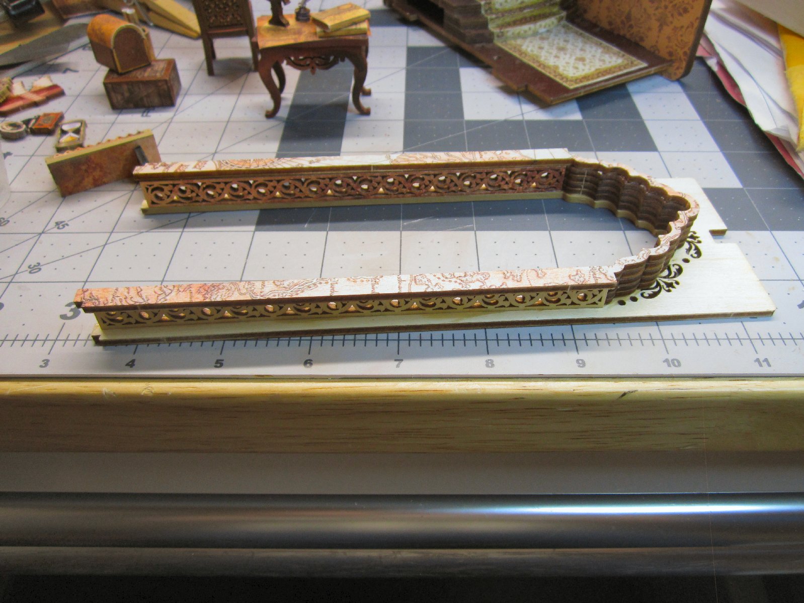
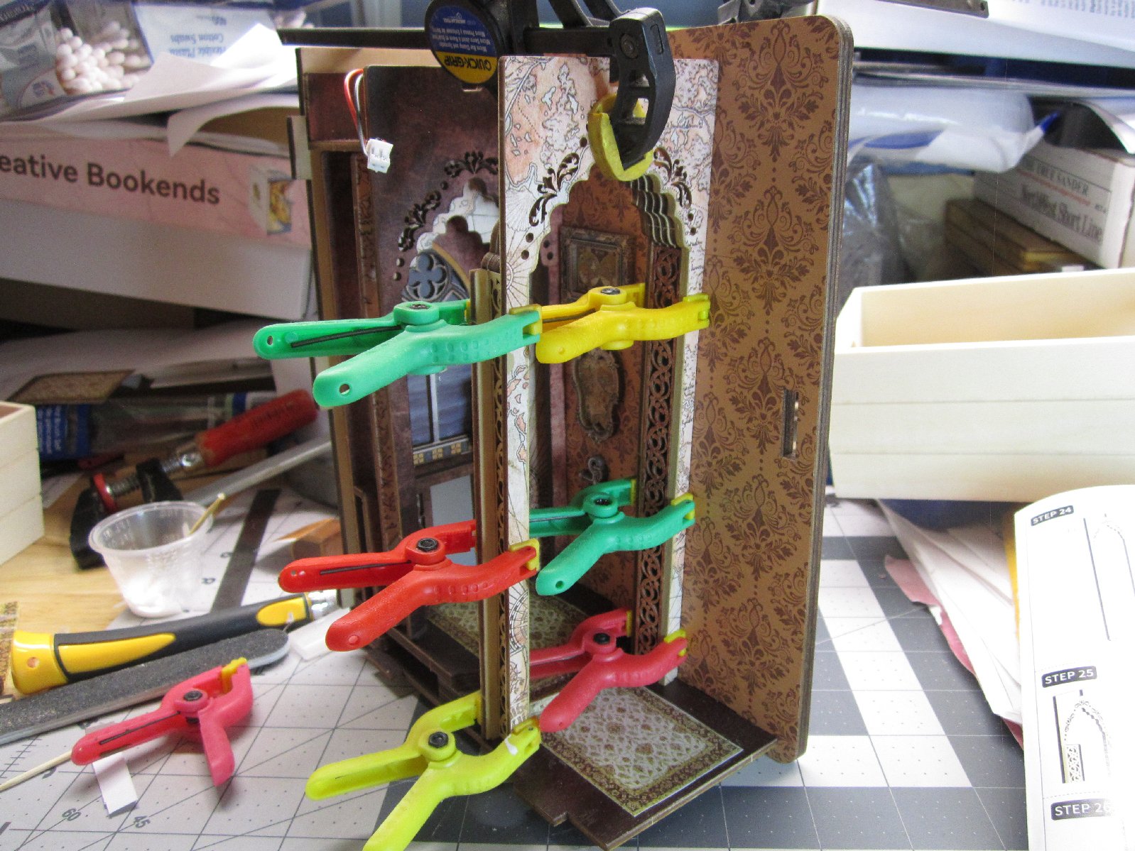
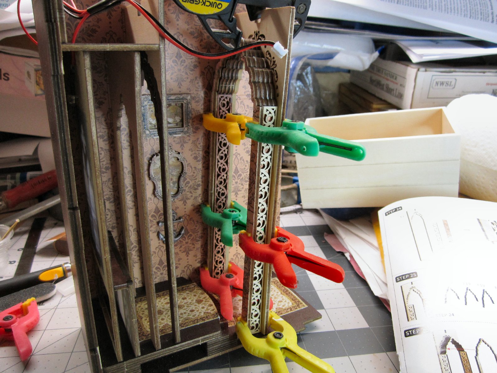
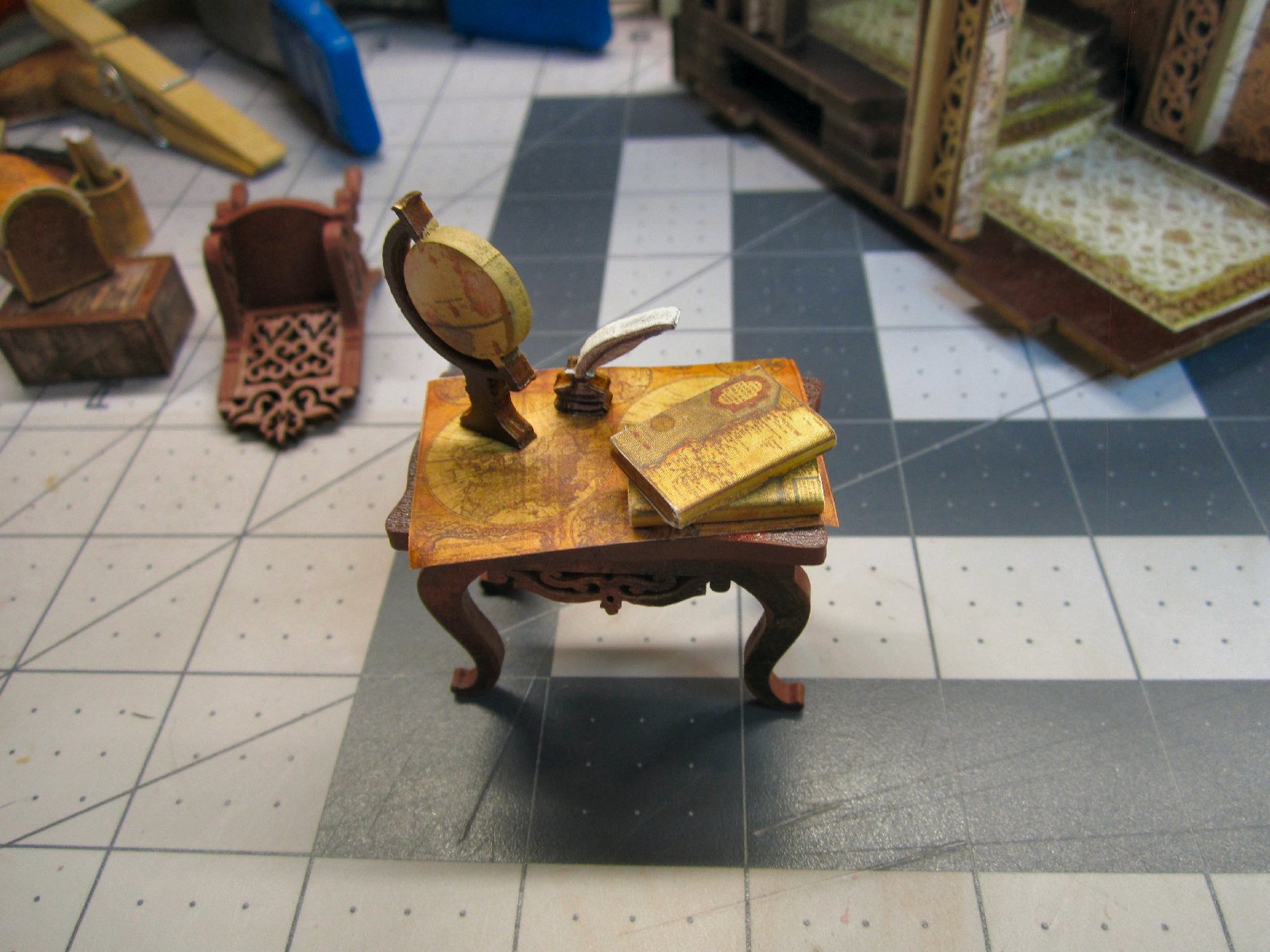
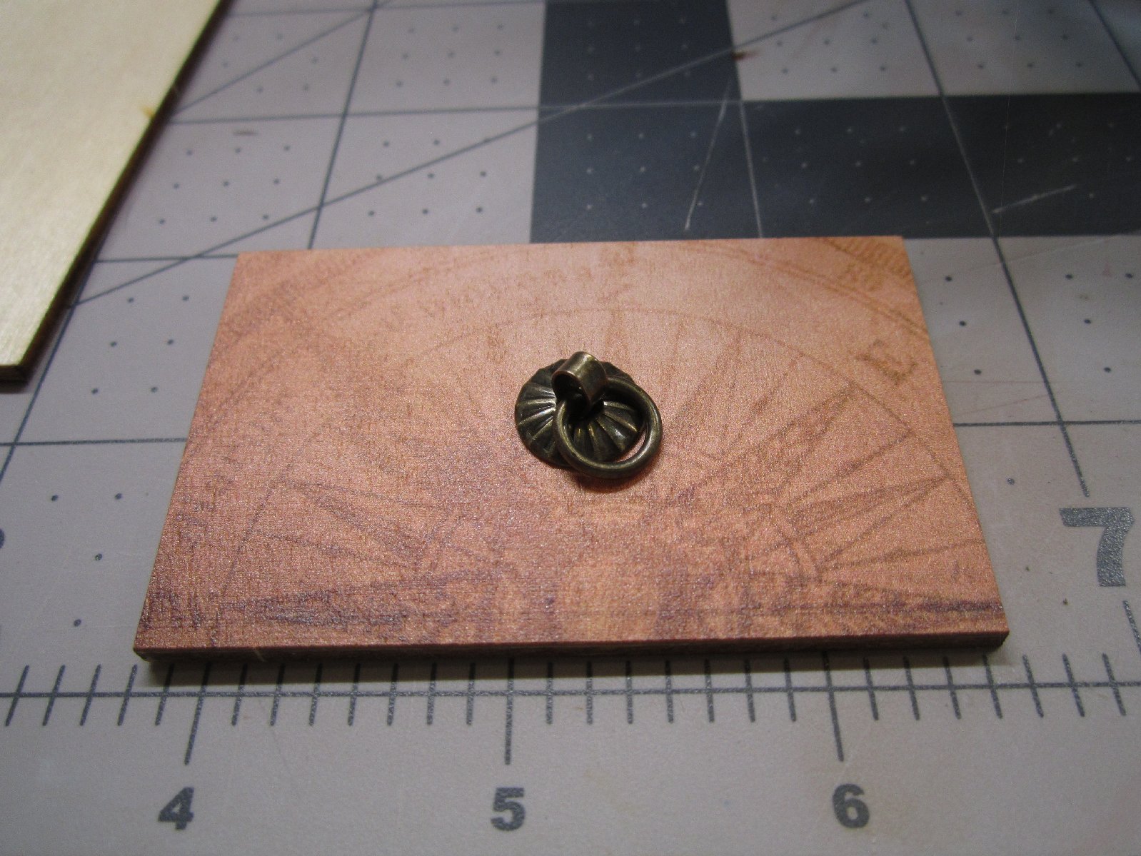
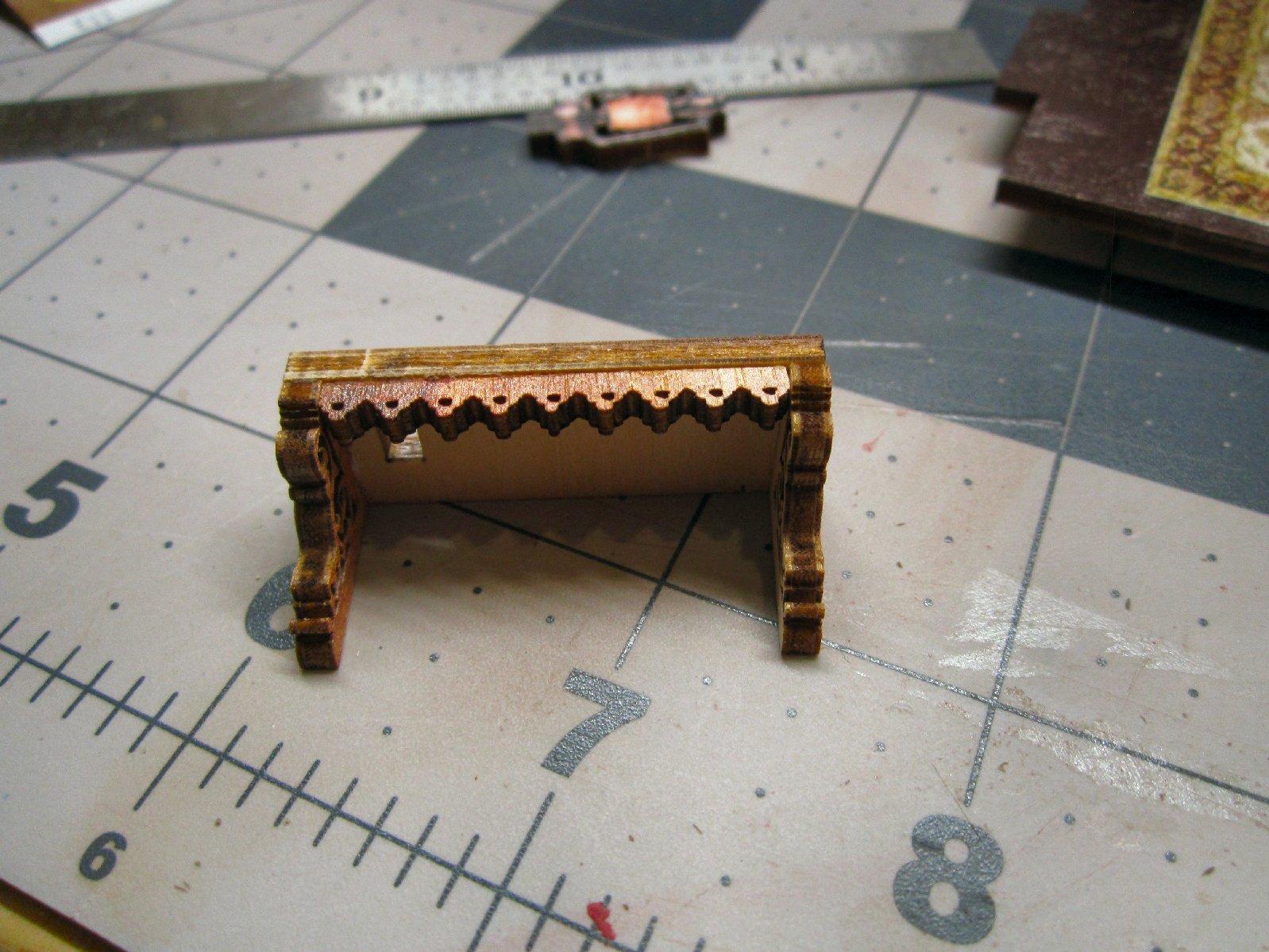
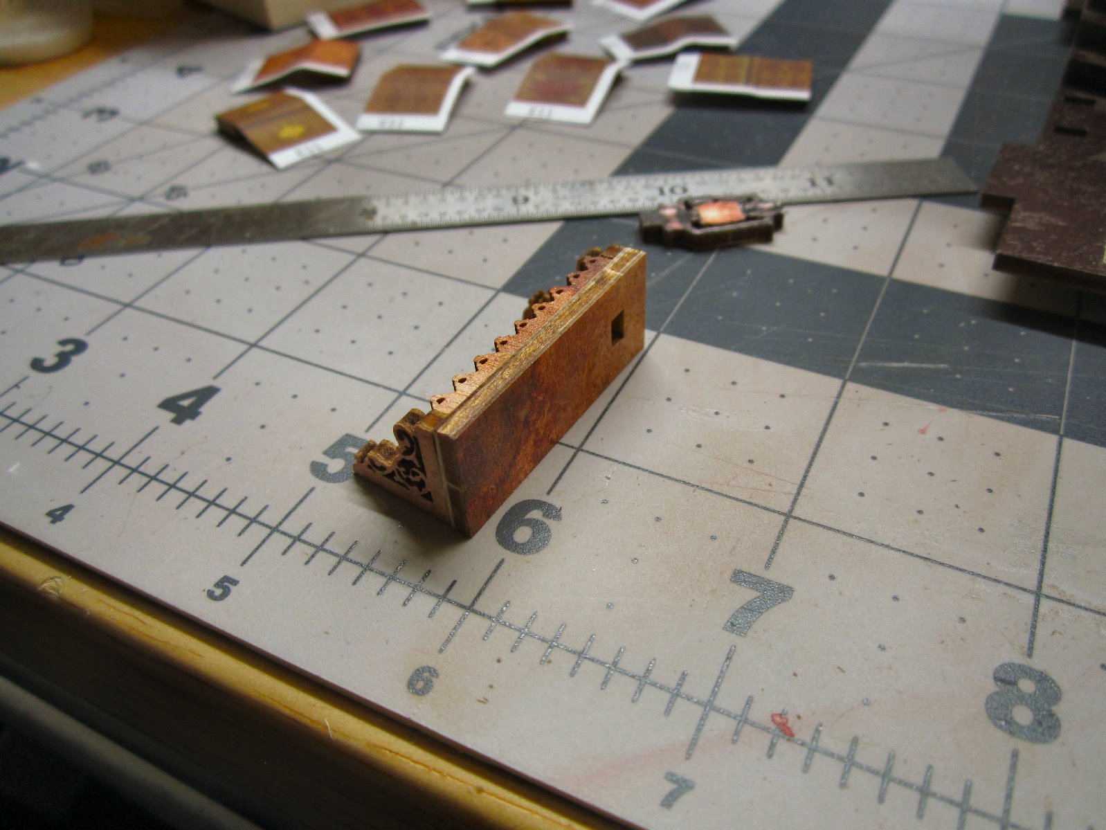
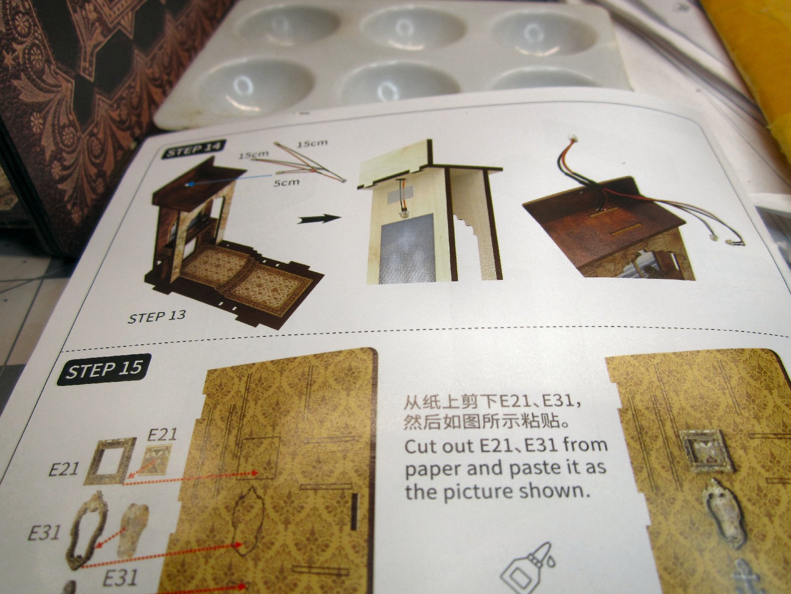
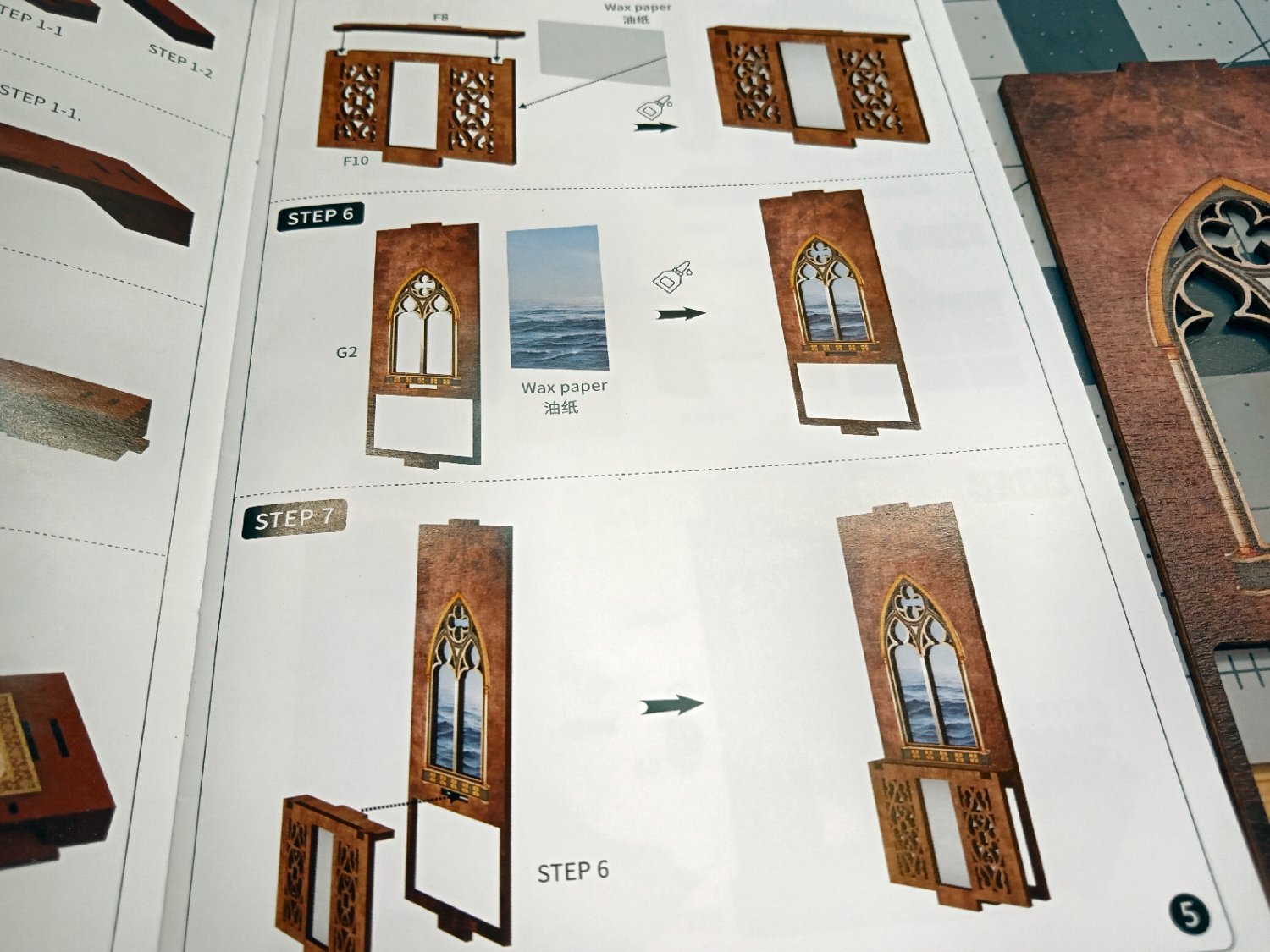
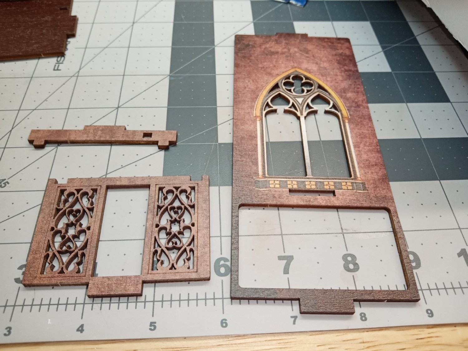
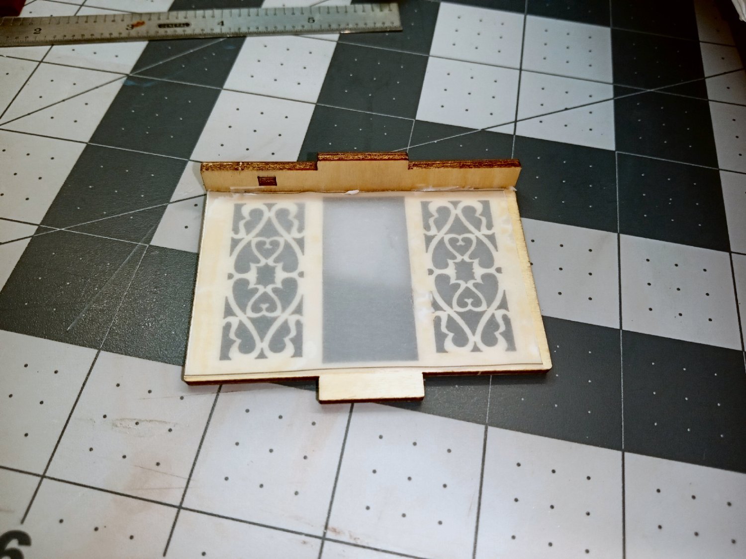
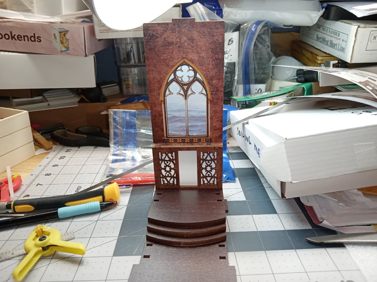
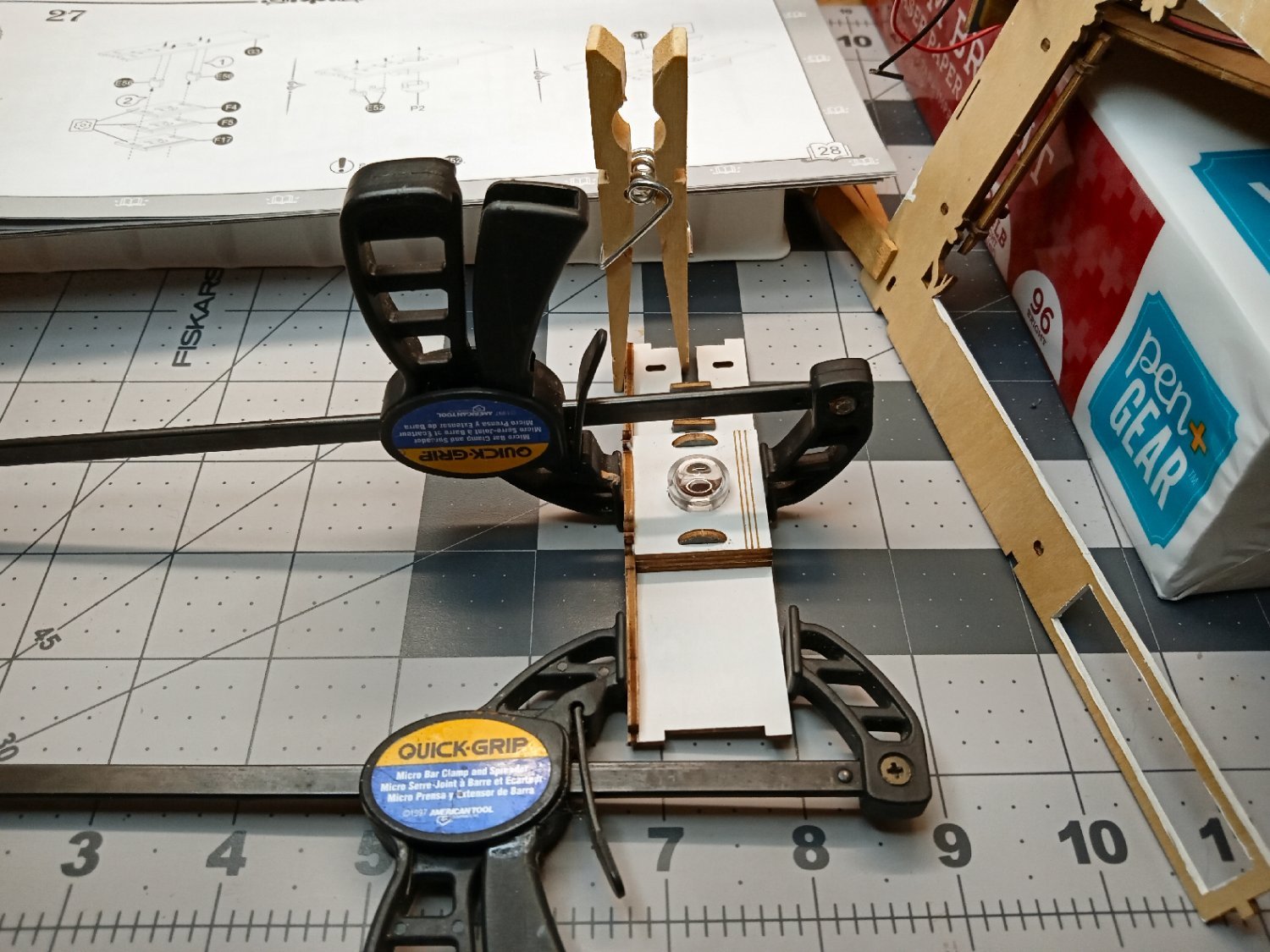
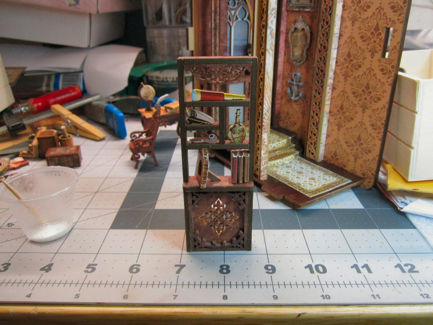
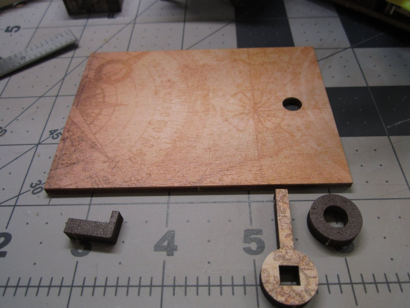
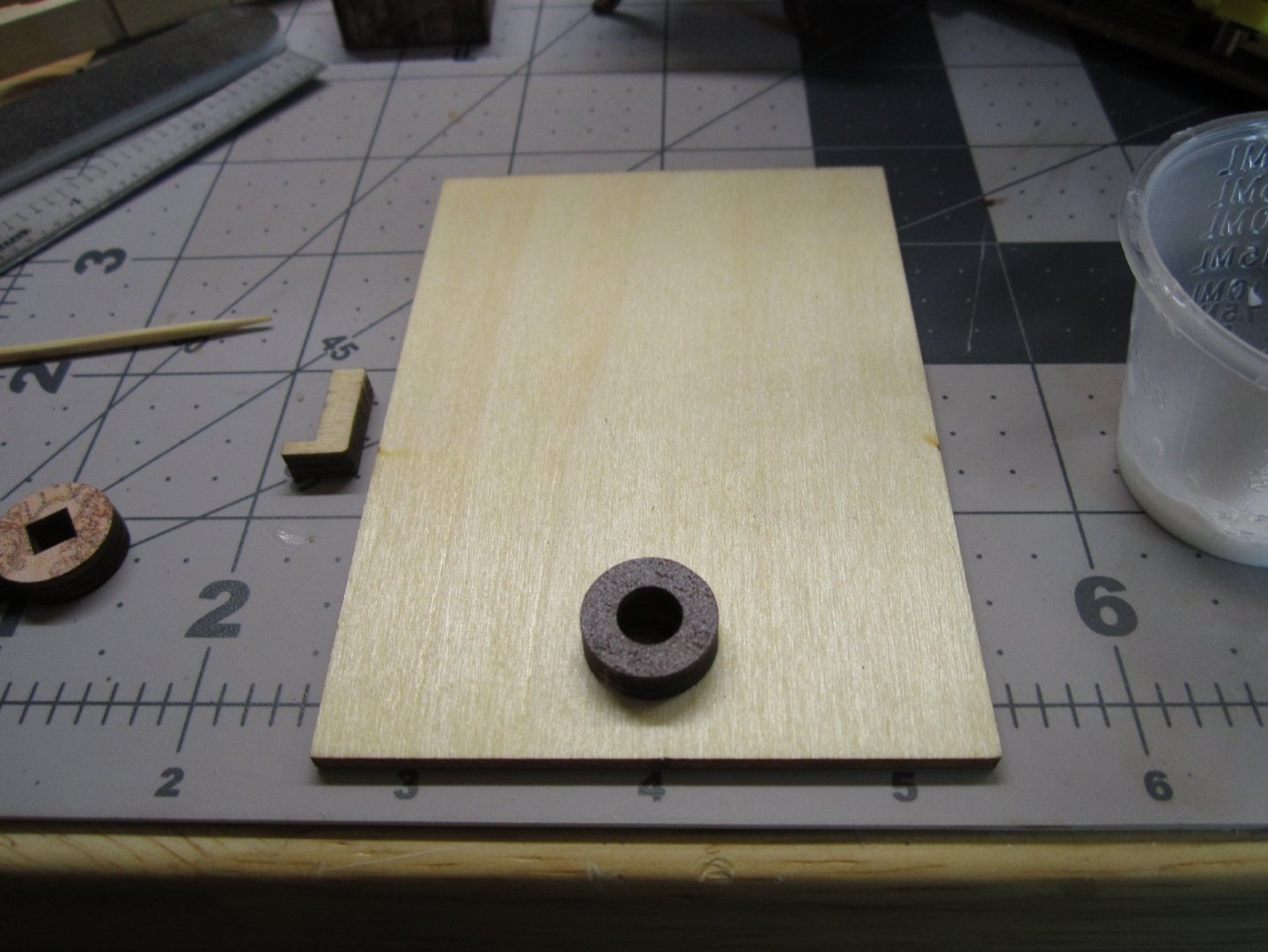
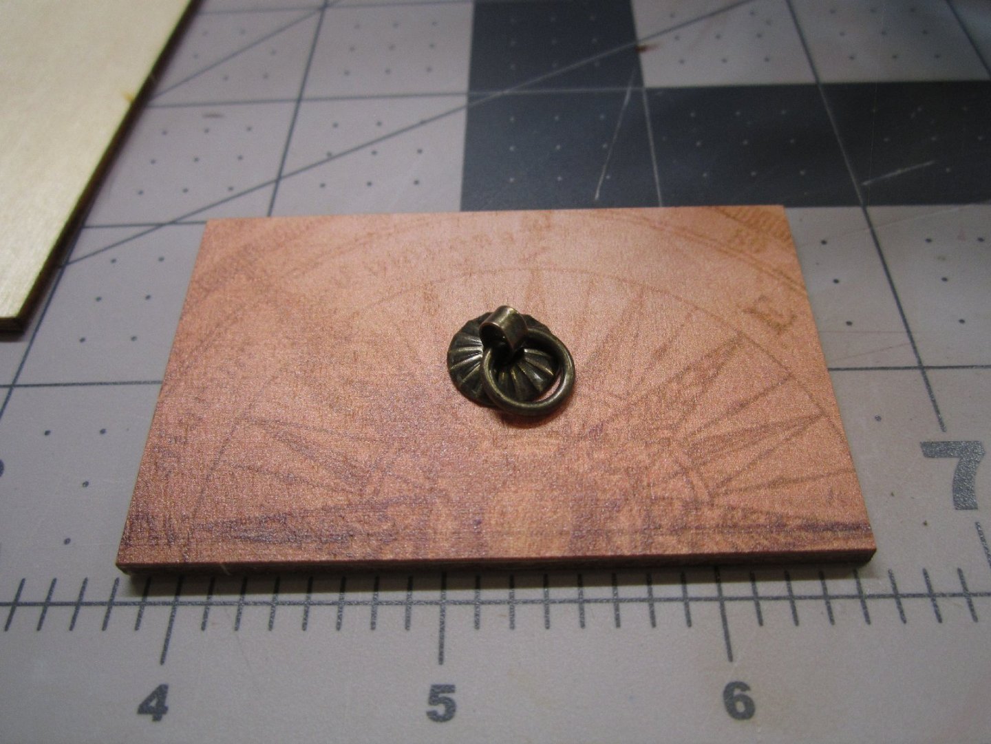
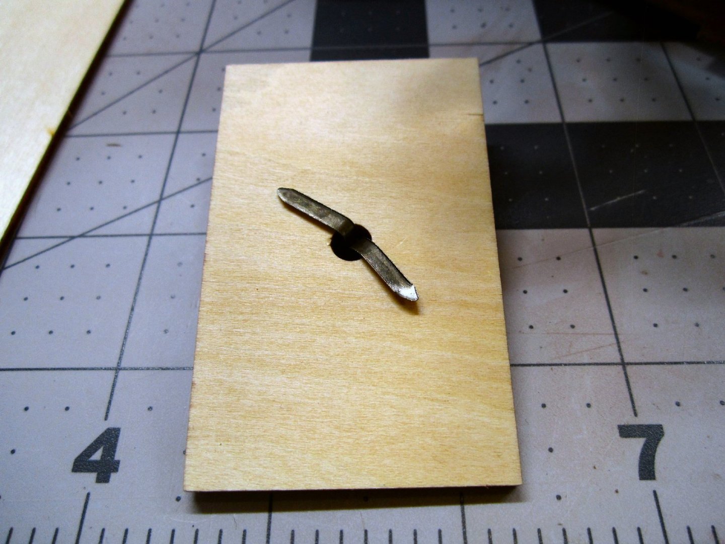
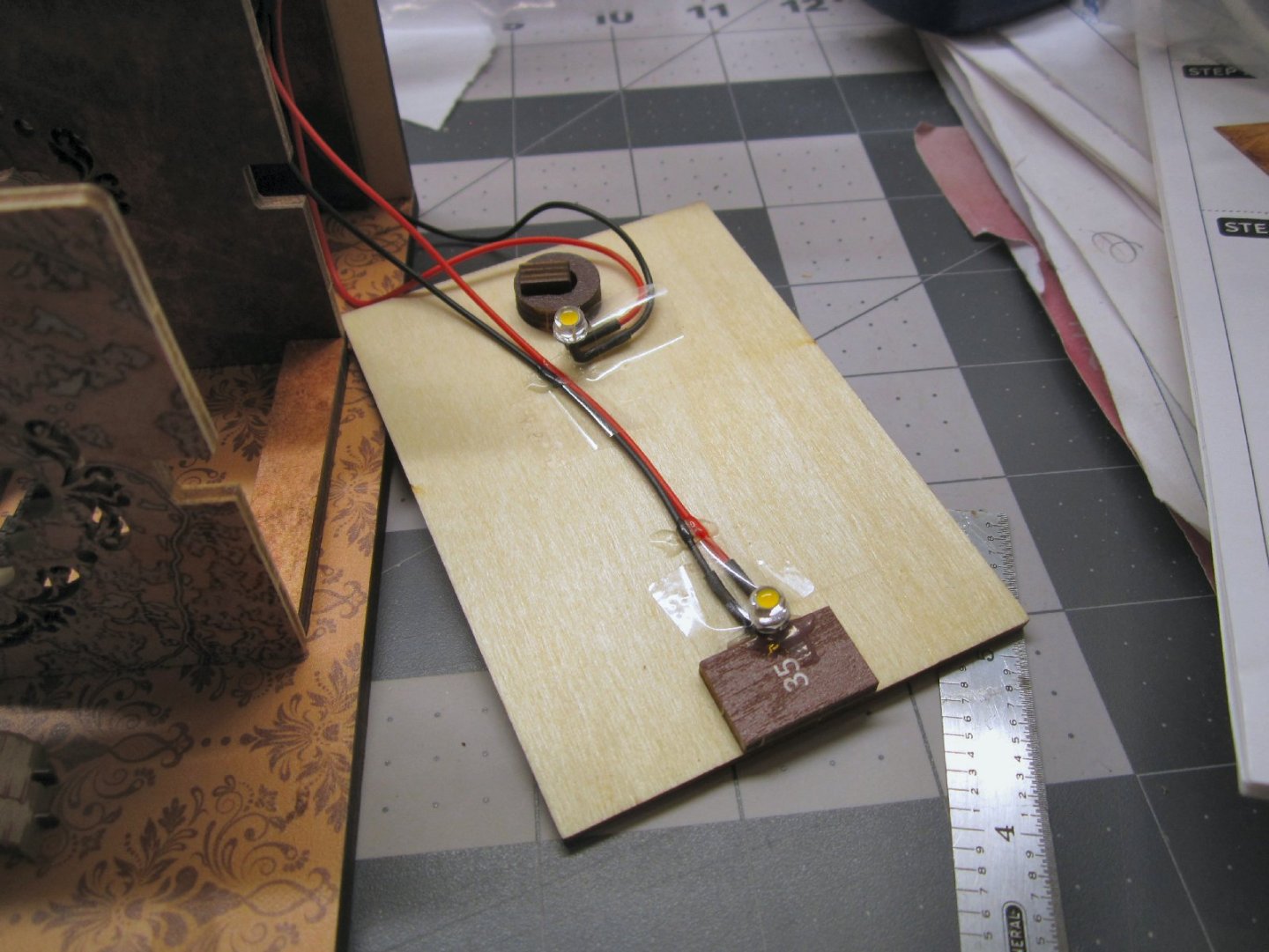
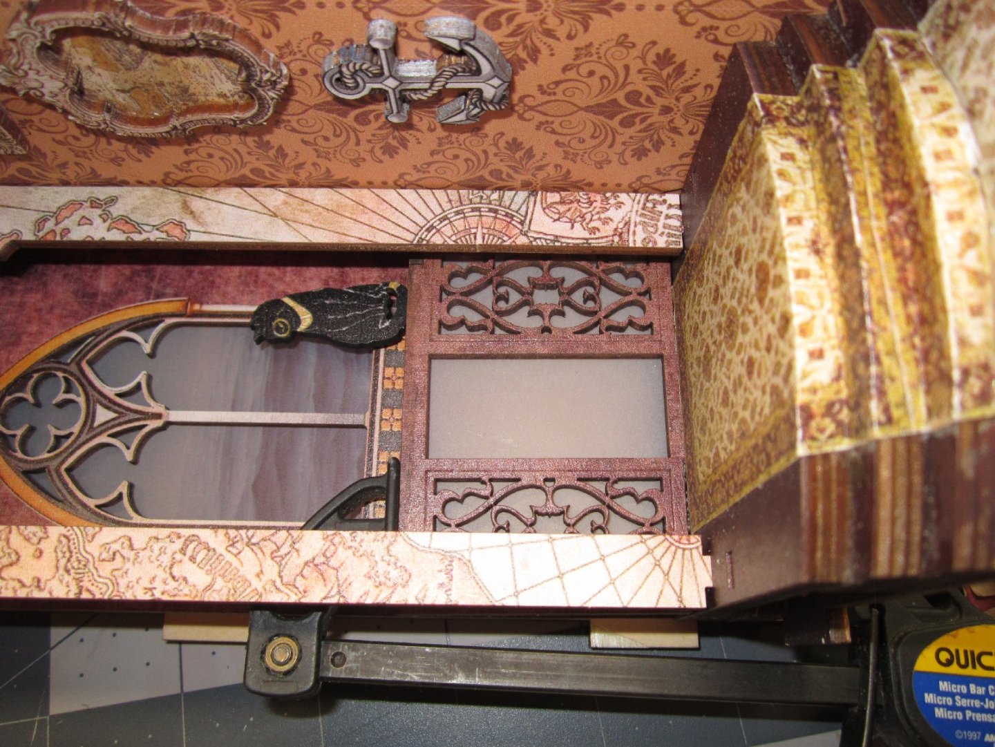
Part 006 The front archway is the next section to assemble. It has a printed front wall with lattice work side walls in the opening, several individual arches to fill the top in, and a printed back wall. This photo shows the lattice side walls and the parts that are layered to form the ceiling of the arch, glued to the front wall. In this picture the printed back wall has been glued on. The printing on this wall will never be seen, but it was nice that they added this detail. Once all the parts were glued. I set the assembly in the model, and clamped it, to hold all the pieces in alignment. This is what the finished assembly looks like in place. At this point it was not glued to the model, I have other parts to go in first. The details were added to the table, next. The top is covered in a map, which hides the exposed tab ends, a globe, an ink well and quill, and the two large books. I painted the edge of the quill off-white, used a gold-yellow pencil for the edges of the globe, and chocolate brown paint, for the globe frame. When the glue dried, I glued the chair and table into the back of the scene, as well as four upright, and one leaning book onto the top of the cabinet (one the left). The details were then added to the shelving unit, as well as the scroll work at the top of the shelves. Finally, three books were glued behind the picture frame. A part was glued in that serves to support one side of the ceiling, and space the top of the front arch. The ceiling over this section was assembled, next. It will span the area from the brown arch, to the back of the front of the model. The other two LEDs are attached to the underside of this to light the interior. This ceiling will be glued in place, and has a hold down latch for the piece that covers the battery box. The four parts of the ceiling are shown, below. The doughnut shaped ring, is glued to the underside of the ceiling as part of the latch assembly. To complete the ceiling, the “L” shaped part is pushed through the hole with the short leg positioned at the doughnut, and the handle is glued to the protruding section. The “L” and the handle must be free to turn in the hole. The LEDs are bent at 90 degrees and glued in place on the underside of the ceiling. To position the LED at the front, of the model, one of the extra book blanks is glued at the front. Care must be taken that the wires for the front LED run down the center of the part. There are notches in the tops of the arches these for them to run through. I taped the wires in place, then glued them down. The wires that exit at the back will be twisted together to fit through the notch there. The battery cover is the next part to build, it is a simple piece. This is a decorated plywood sheet with a central hole, the fancy fixture is installed in the hole as a handle for the cover. The fixture is a flat pin that captures the washer and ring. The pin is pushed through the hole, and bent over on the back side. Part 7 will cover the completion of the model.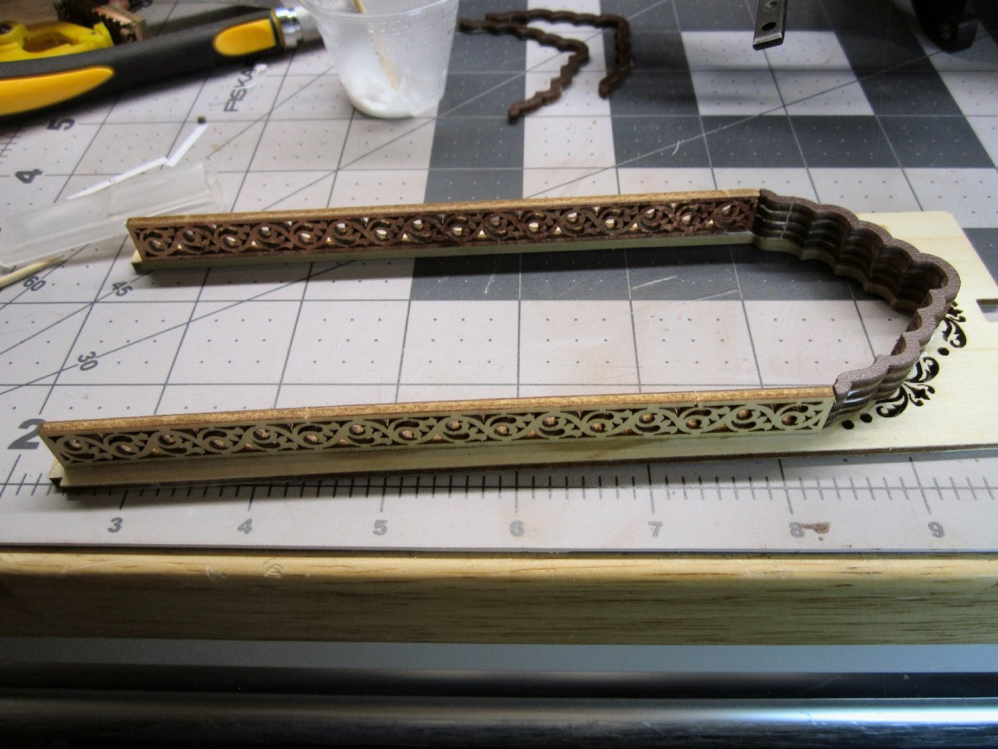


-
"Sailing Memory" by thibaultron - Book Size Diorama
thibaultron replied to thibaultron's topic in Non-ship/categorised builds
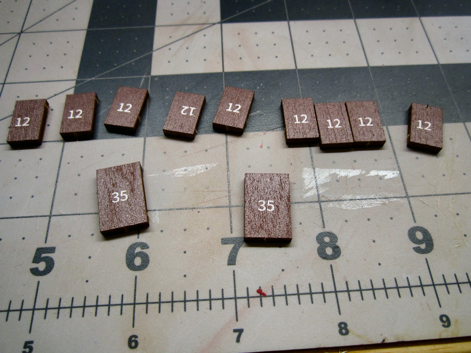
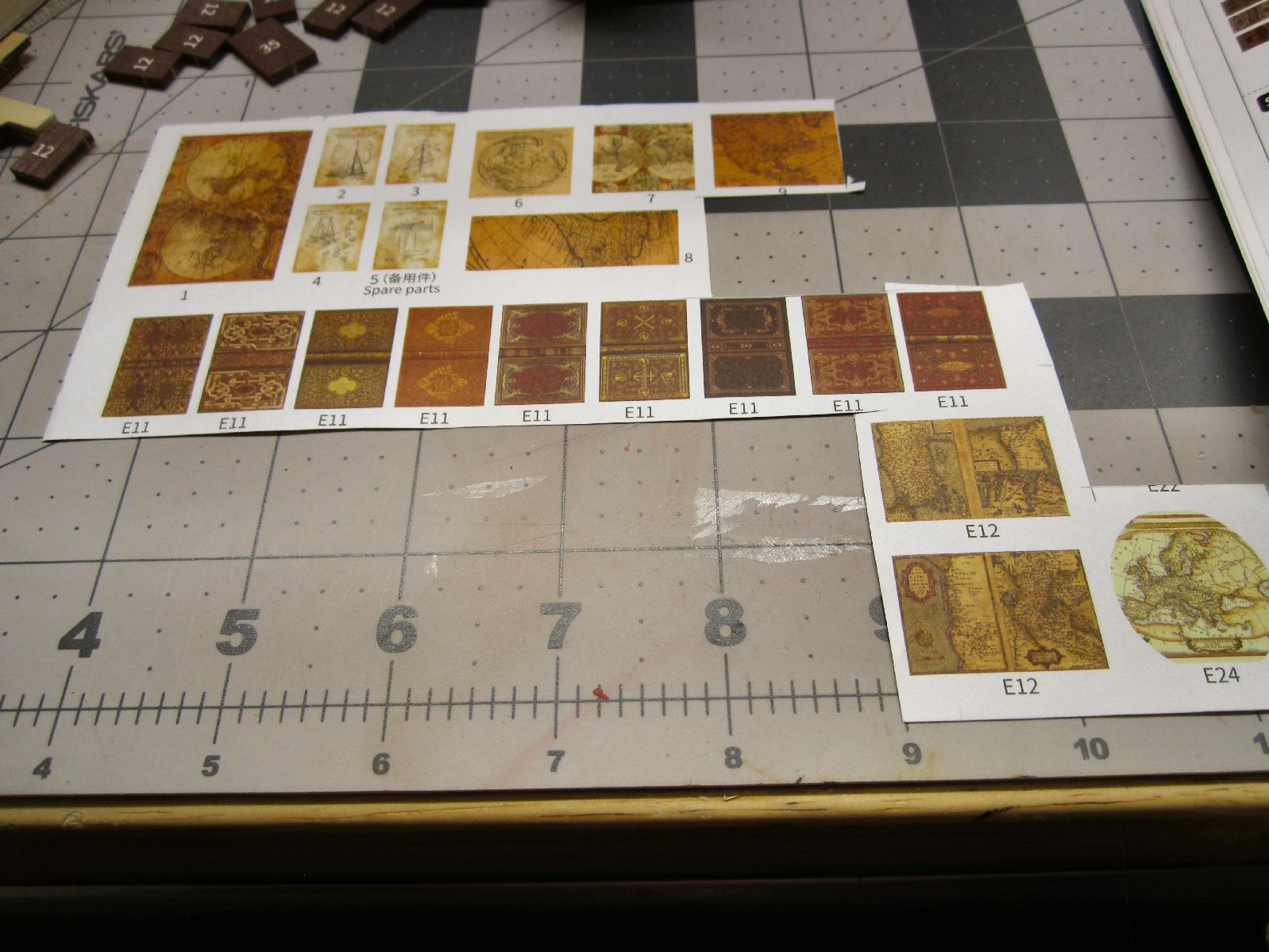
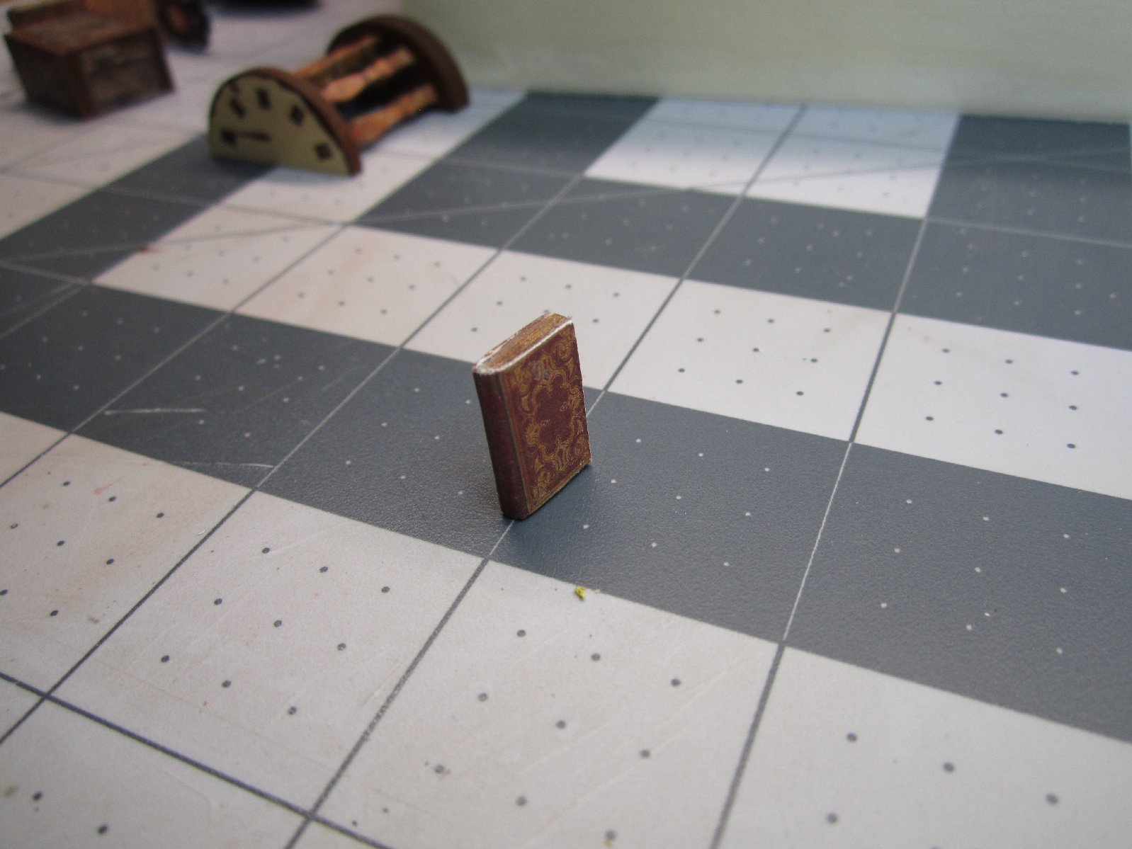
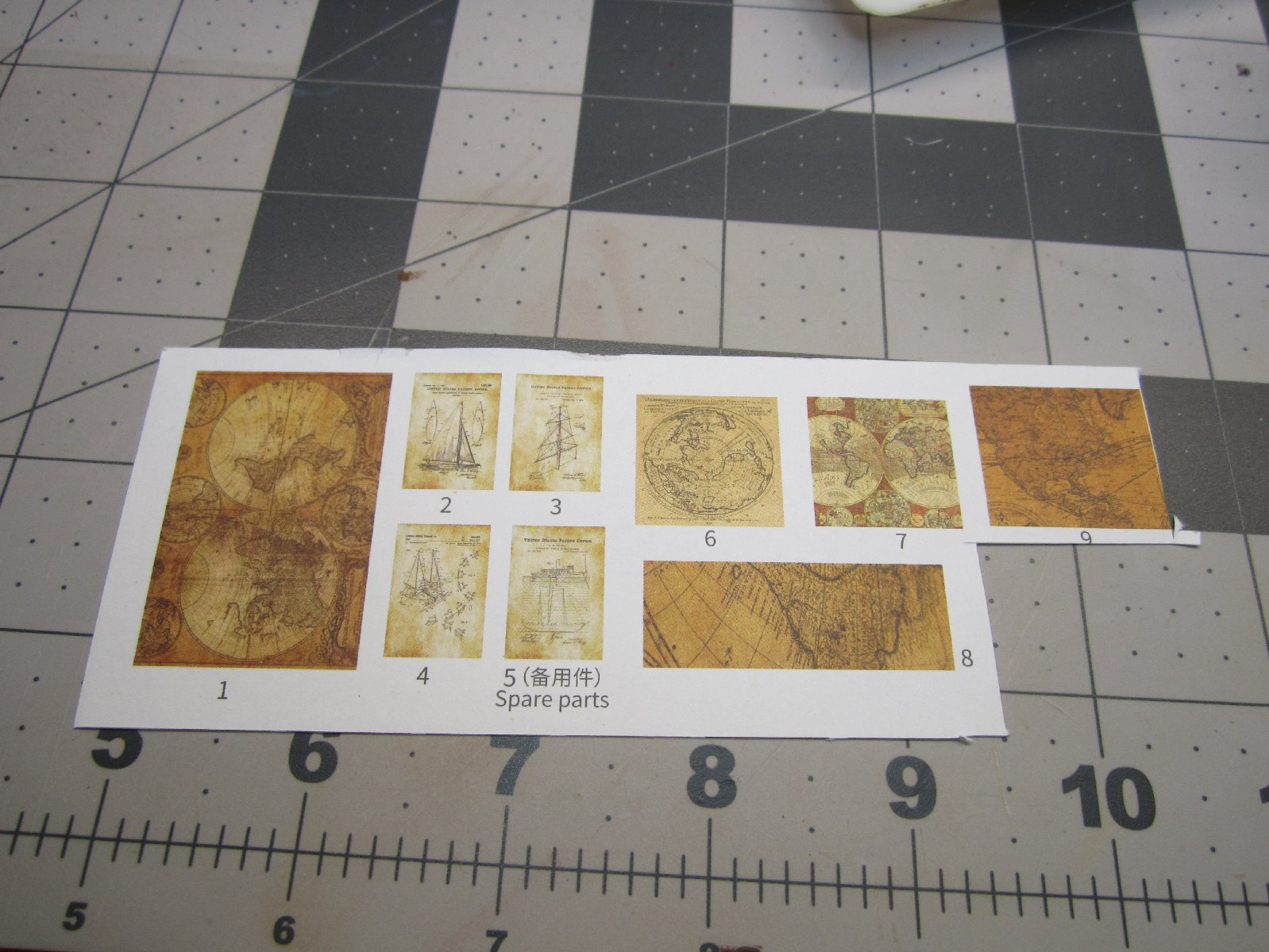
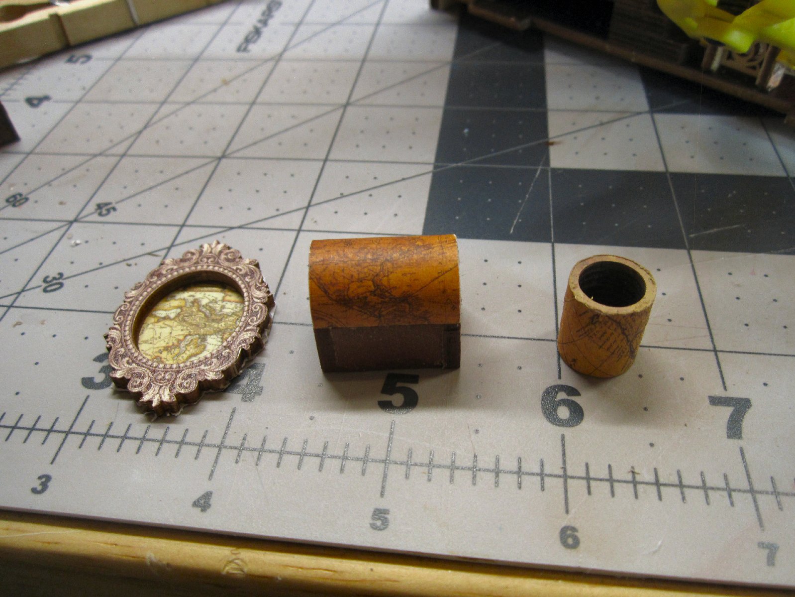
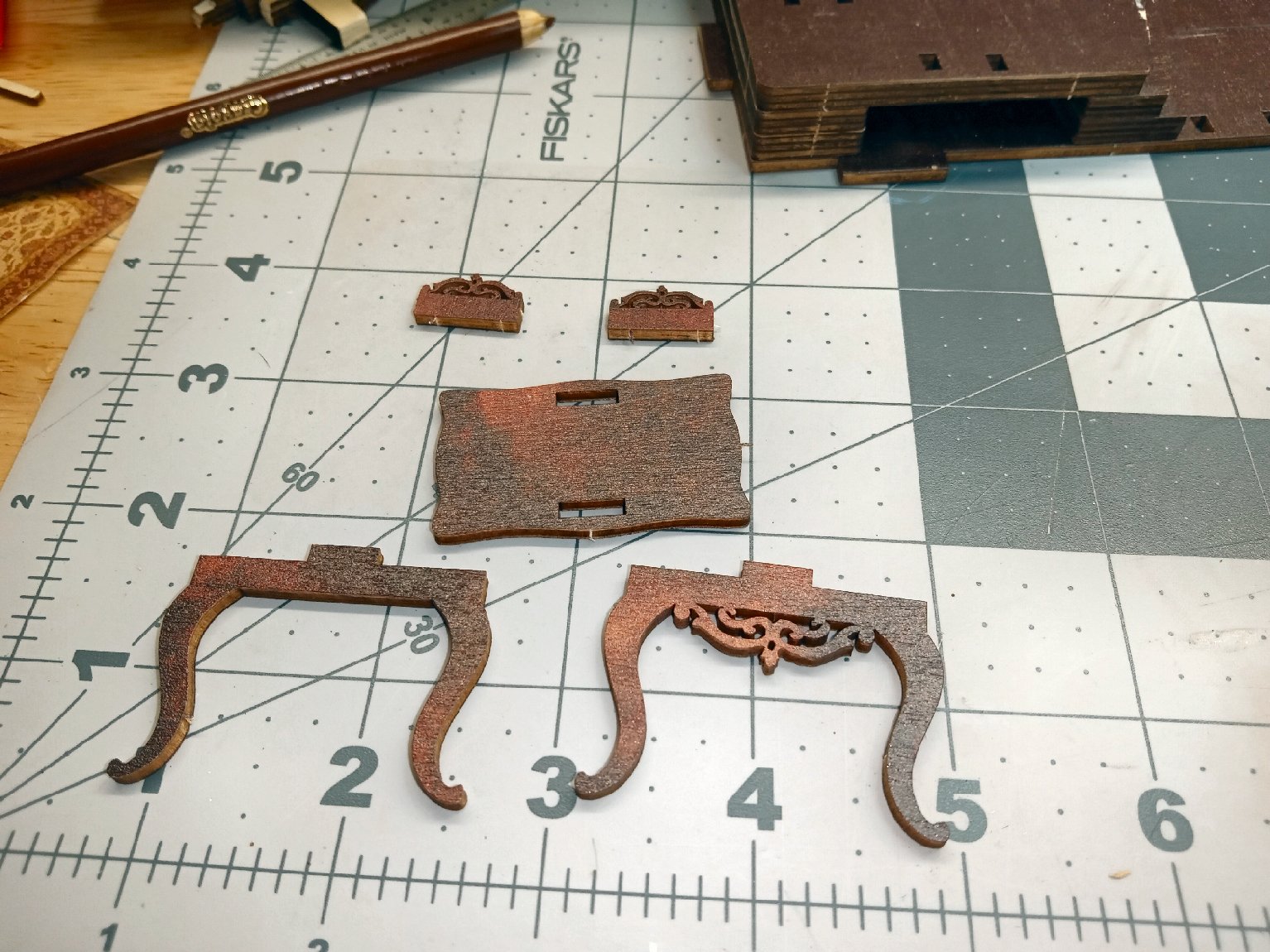
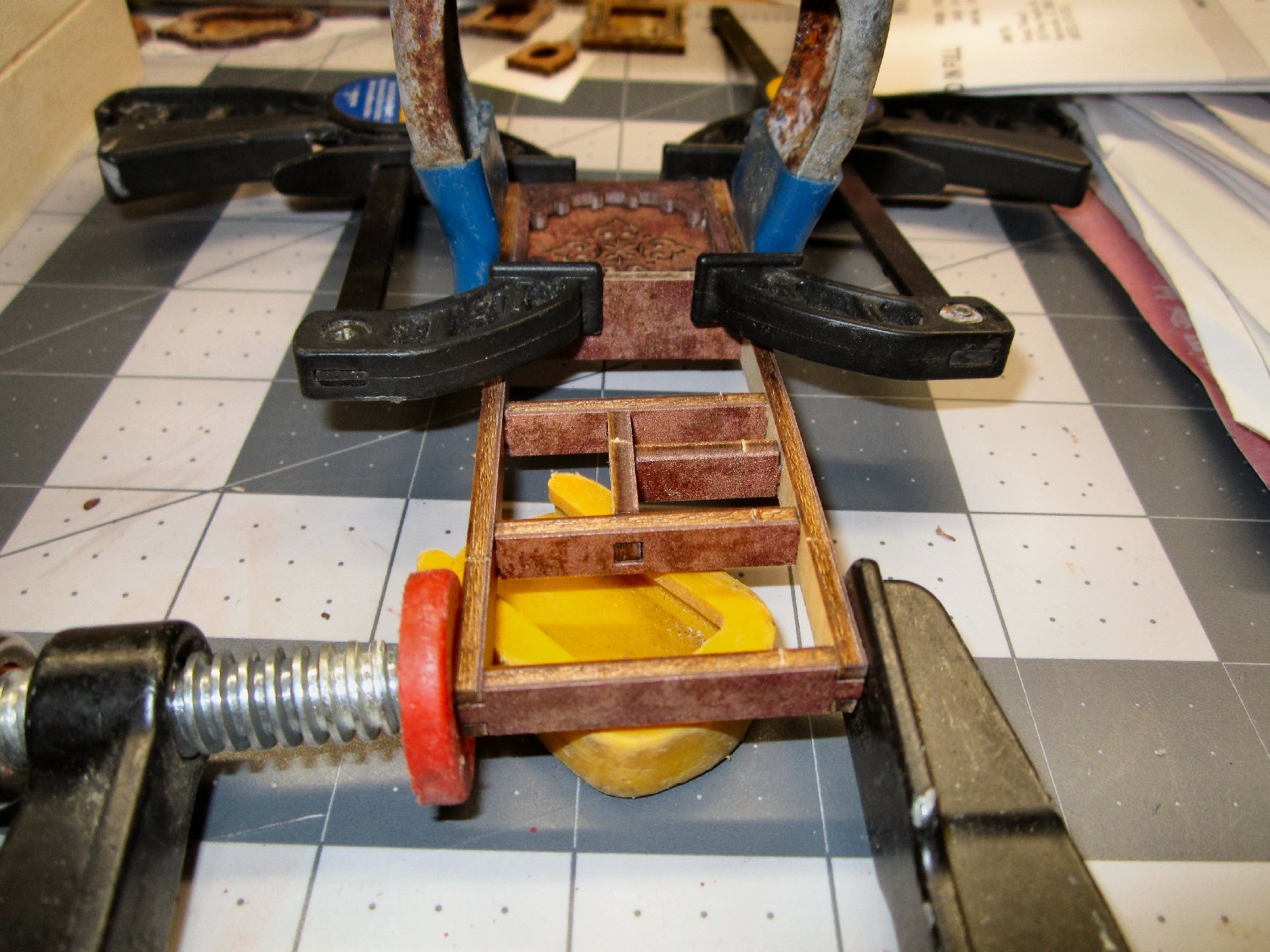
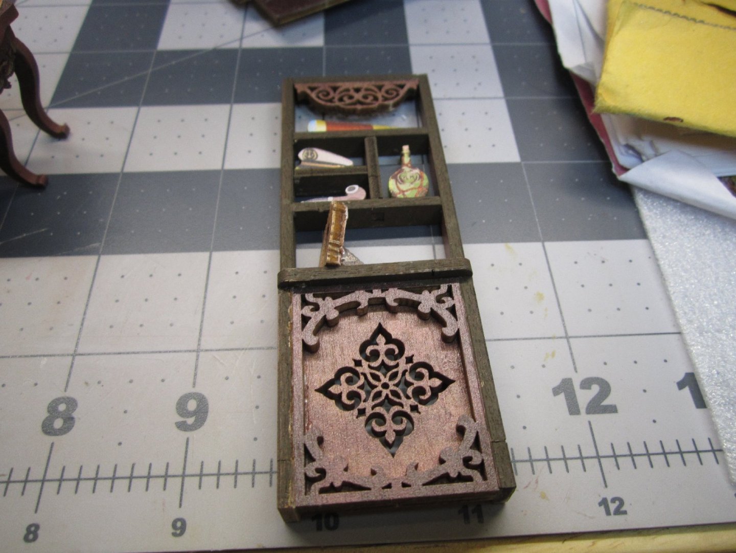
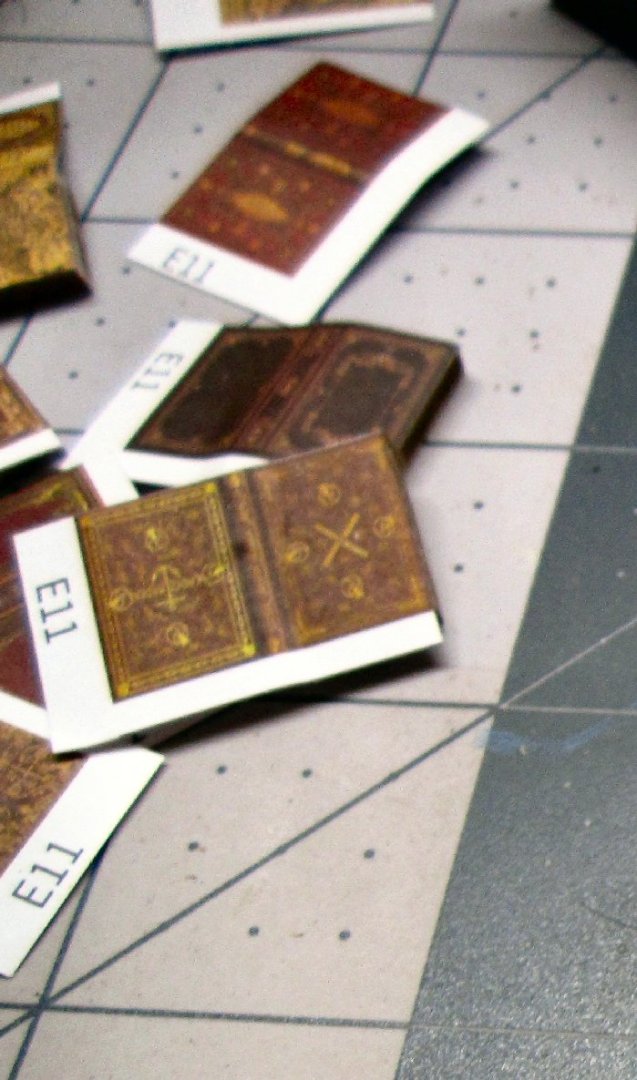
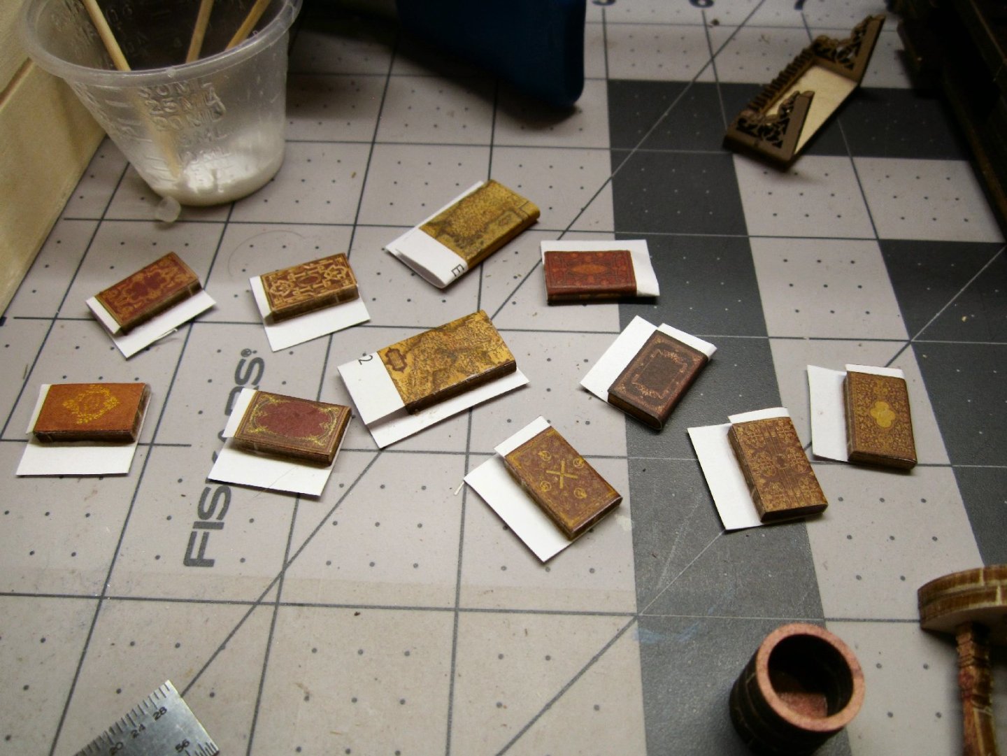
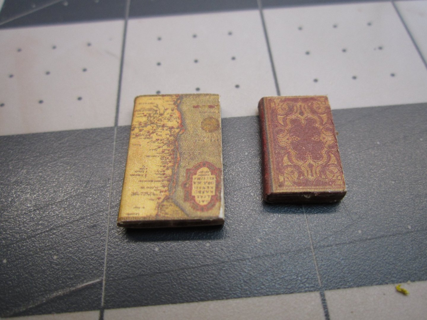
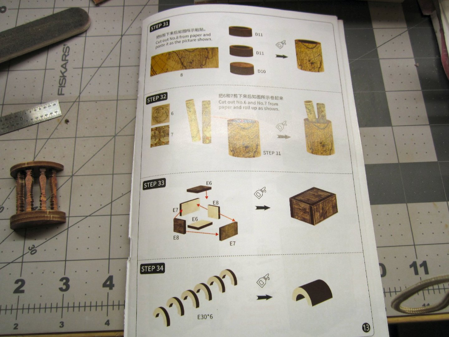
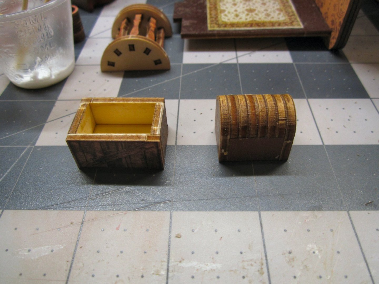
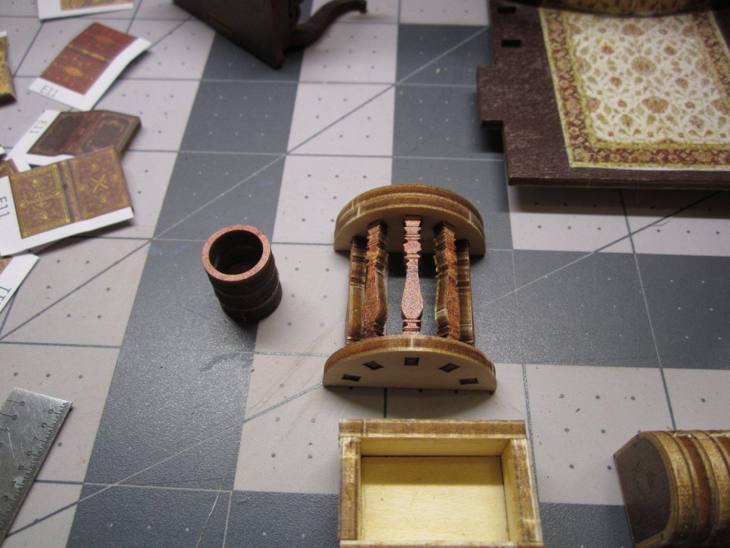
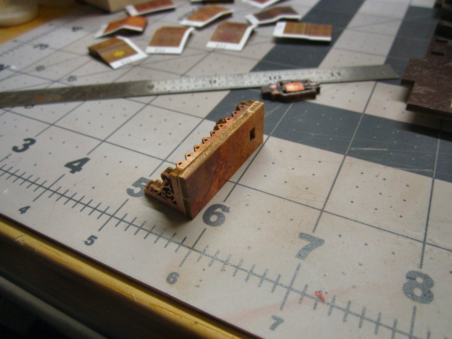
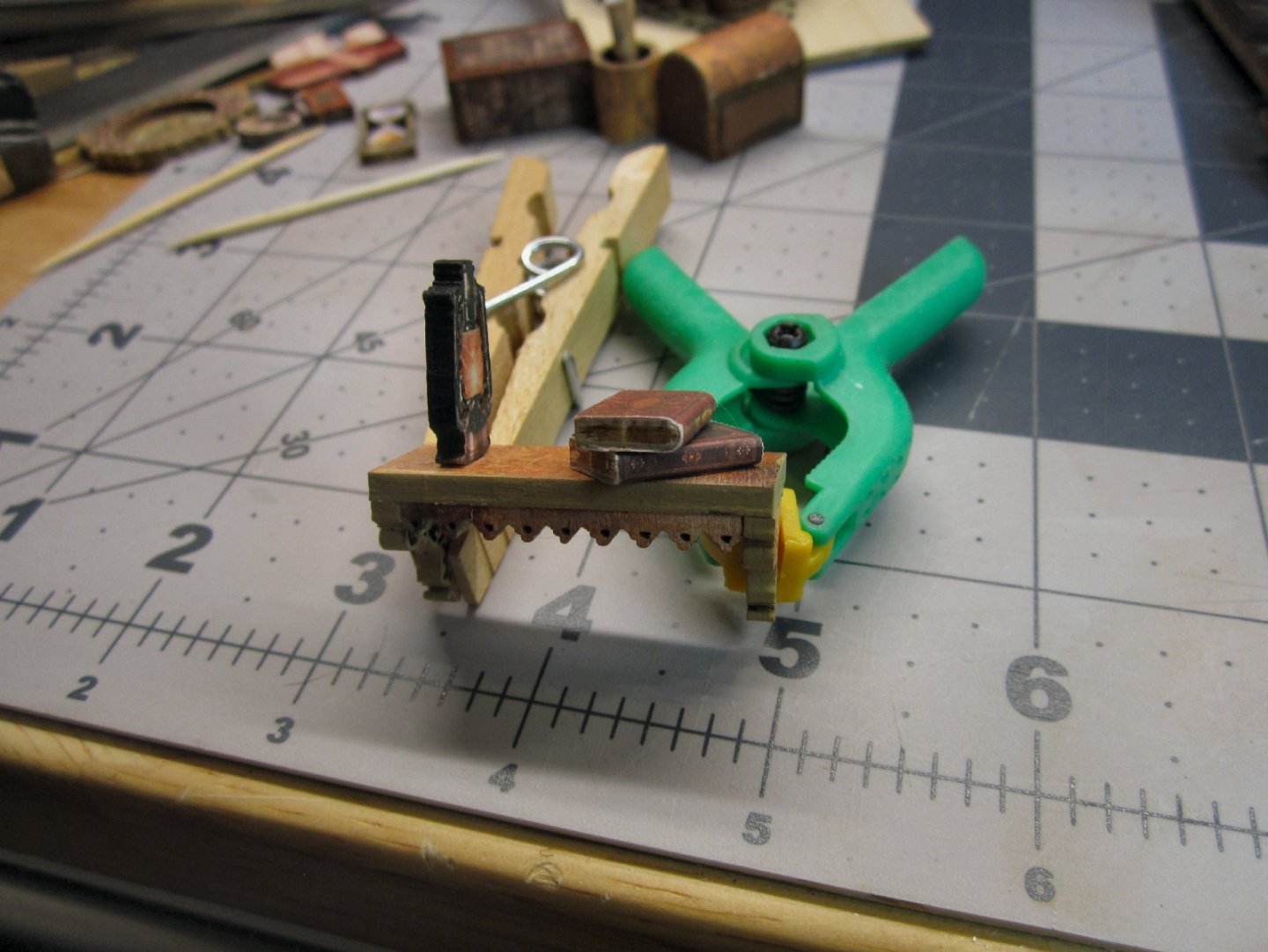
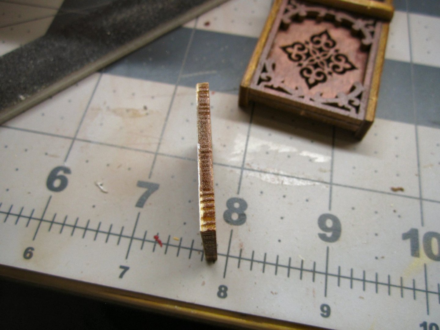
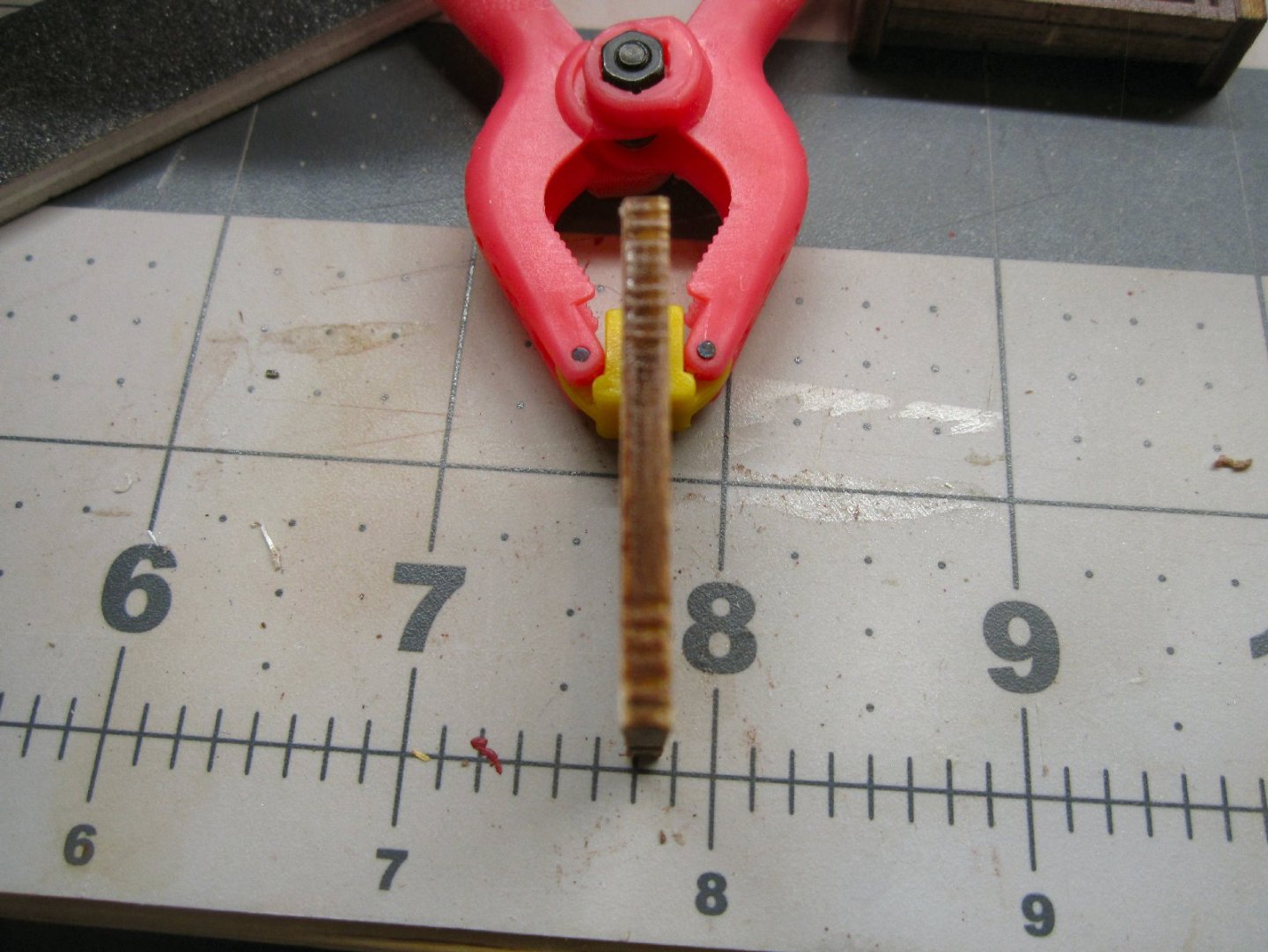
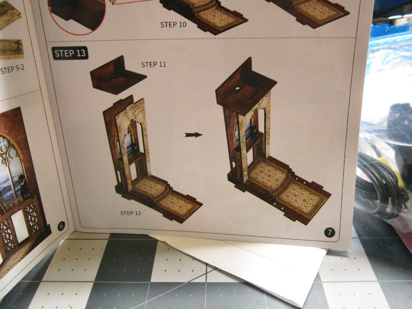
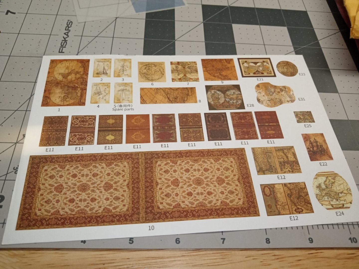
Part 005 I tackled the books next. The kit supplies wood blanks and printed covers to be glued on them. This picture shows the raw blanks, nine for small books, and two blanks for large ones. The printed covers are shown below, they are the E11 and E12 graphics. I started by sanding the edges of the blanks, to smooth off the holding tabs the laser left. I then rounded one long edge to represent the spine, and also to allow the cover to flow smoothly around those corners. I trimmed the covers on one long edge and one short edge, leaving one completely trimmed corner Then, I separated each cover Leaving as much unprinted area as possible, to use as handles. The trimmed edges formed the end of a cover, and the base of the book. I applied glue to the cover end edge, and placed the trimmed corner on the blank. I carefully bent the cover around the spine, to make sure everything was lined up, then unbent it, and set the books blank side down, and let the glue dry. After the glue was set, I applied glue to the opposite side of the blank, and the spine area. Then, I bent the cover around and held it in place for a few seconds, until the glue grabbed. I set the books back down, with the glued side down, to hold the cover in place, and let the glue fully dry. After the glue was dry, I trimmed the extra paper away, with a hobby knife, then gently sanded the edges to clean off any extra paper that was left. This photo shows one of the completed small books. This picture shows a large and small book. The next steps are assembling some small details. The photo shows the instructions for some of these. The first is a trash can shaped map holder. The next panels show the crate, and the assembly of the top of a chest. These pictures show these details during assembly I painted the semi-circular table’s exposed areas. Next, came covering the map holder and chest. The number 8 graphic is the map holder cover, and 9 is for the top of the chest. When I went to cover the chest, the print is too short, to cover all of the top, from front to back! If my printer was working, I would have stretched the print, and printed another to use. I painted the exposed top to hide the raw wood, and will have to leave it at that. There is another picture and frame, that is shown further on in the instructions. Graphic number 6 is the picture for that frame. This photo shows the picture, the covered chest, and the map holder, skinned. Later two of the graphics are rolled and glued in the map holder. I painted the top rim of the map holder, as I gouged the printed color, trimming the excess paper. There is a shelf that goes on the right wall, that will hold a few items. The next two photos are the basic shelf assembled. This shot is the shelf with two books and a lantern mounted. I painted the edges of the lantern handles and top black. I forgot about painting the base, before I glued it on. Thankfully the laser char is a close color, to the base.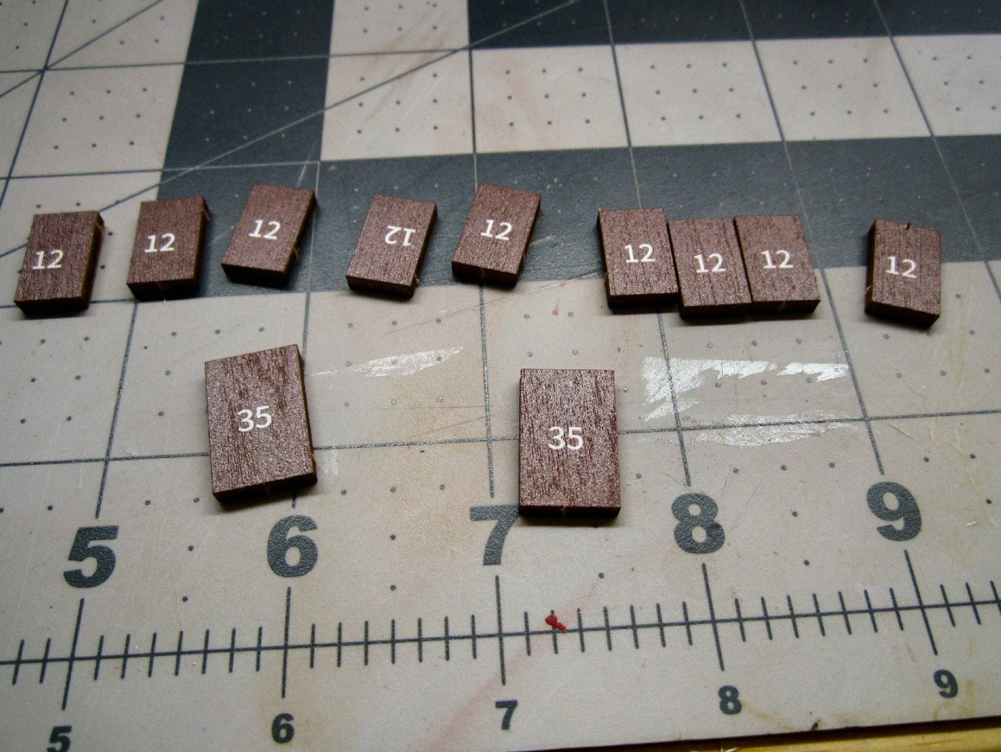


-
"Sailing Memory" by thibaultron - Book Size Diorama
thibaultron replied to thibaultron's topic in Non-ship/categorised builds
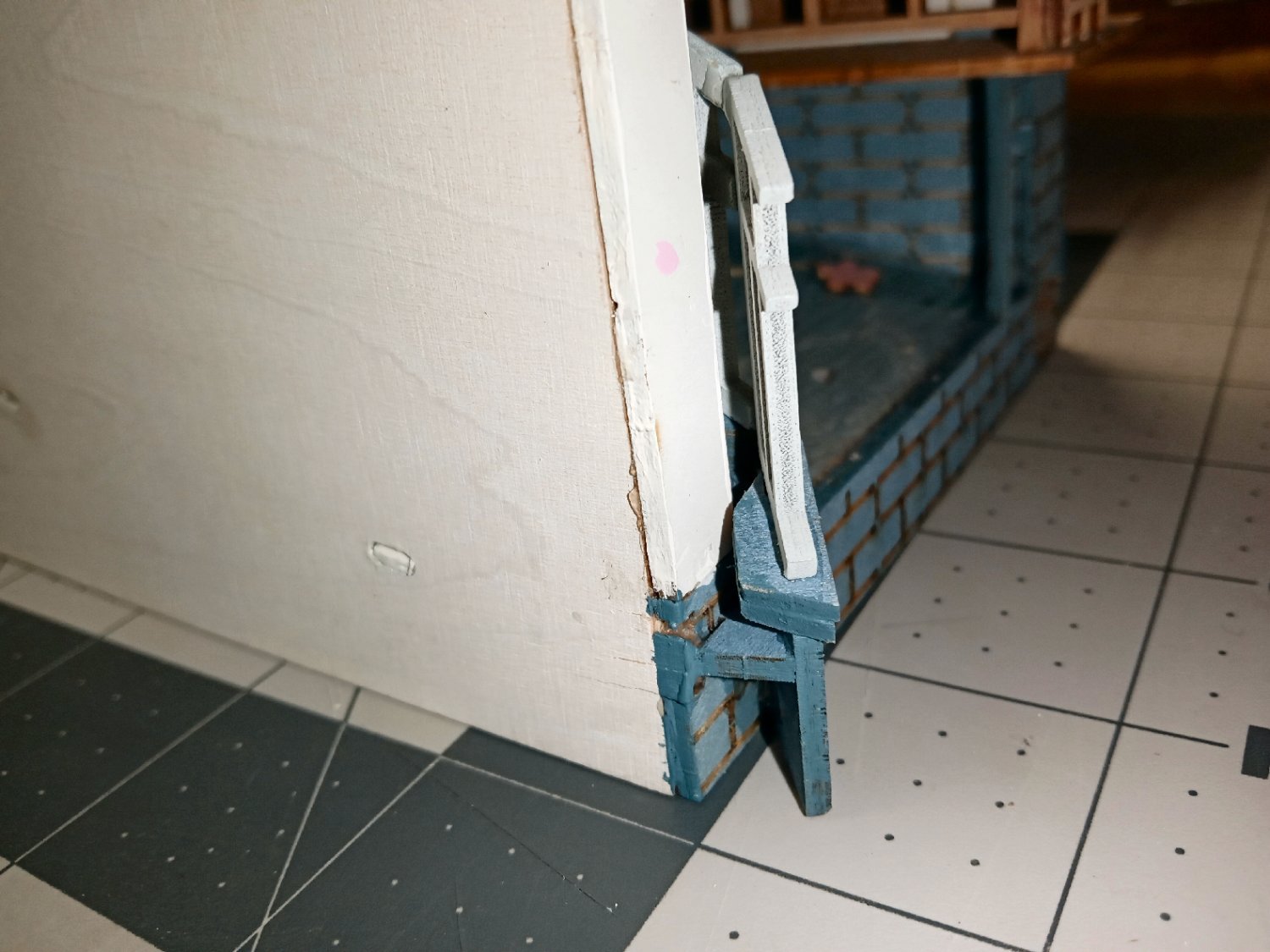
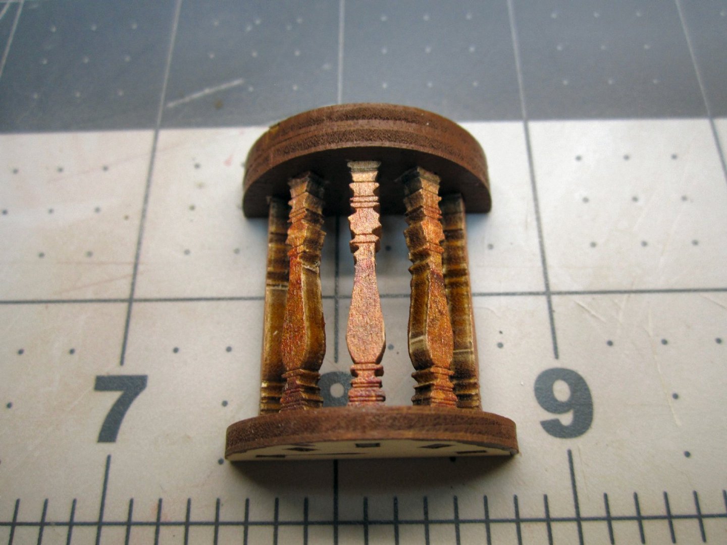
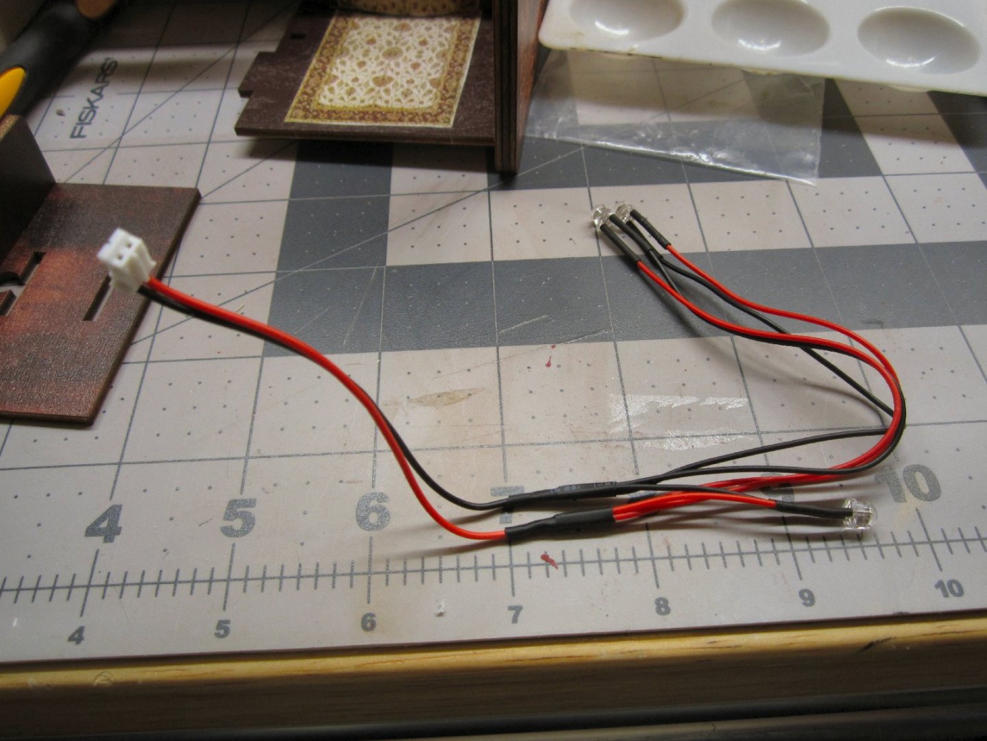
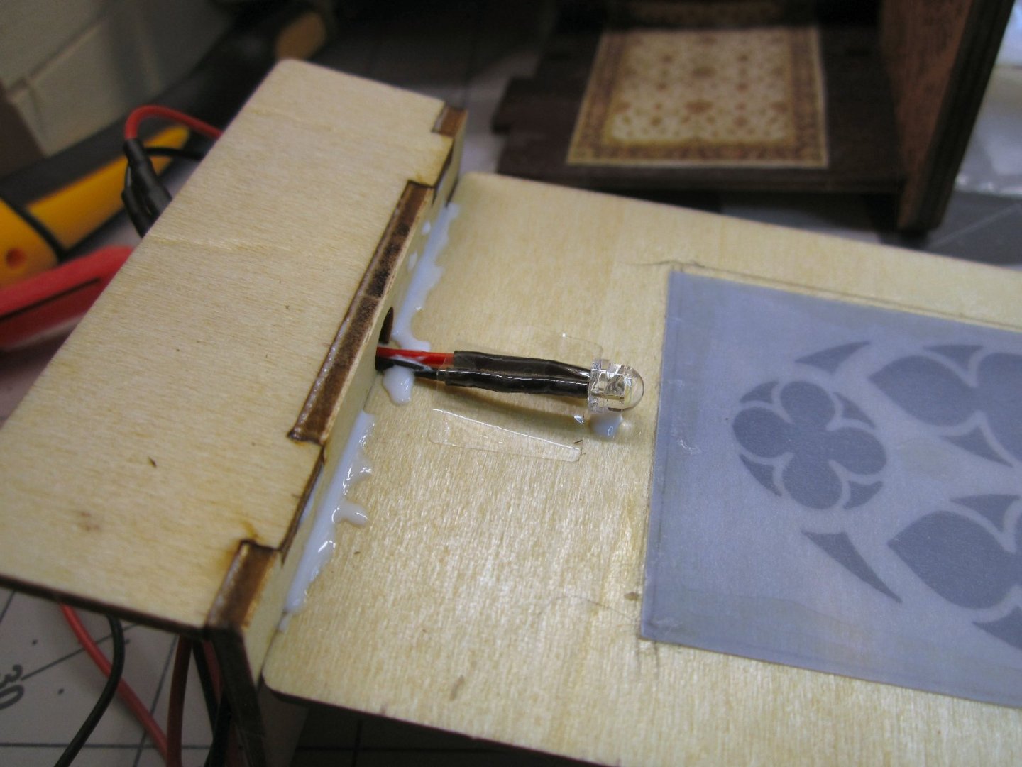
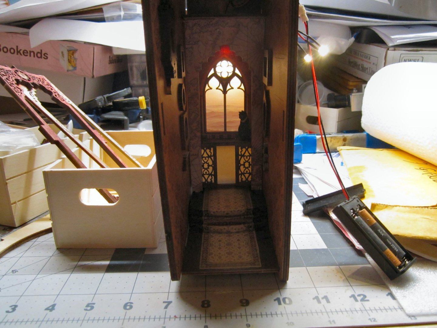
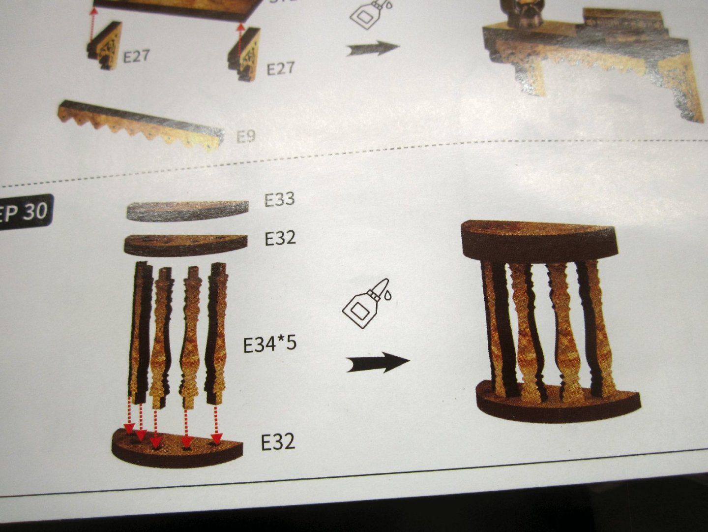
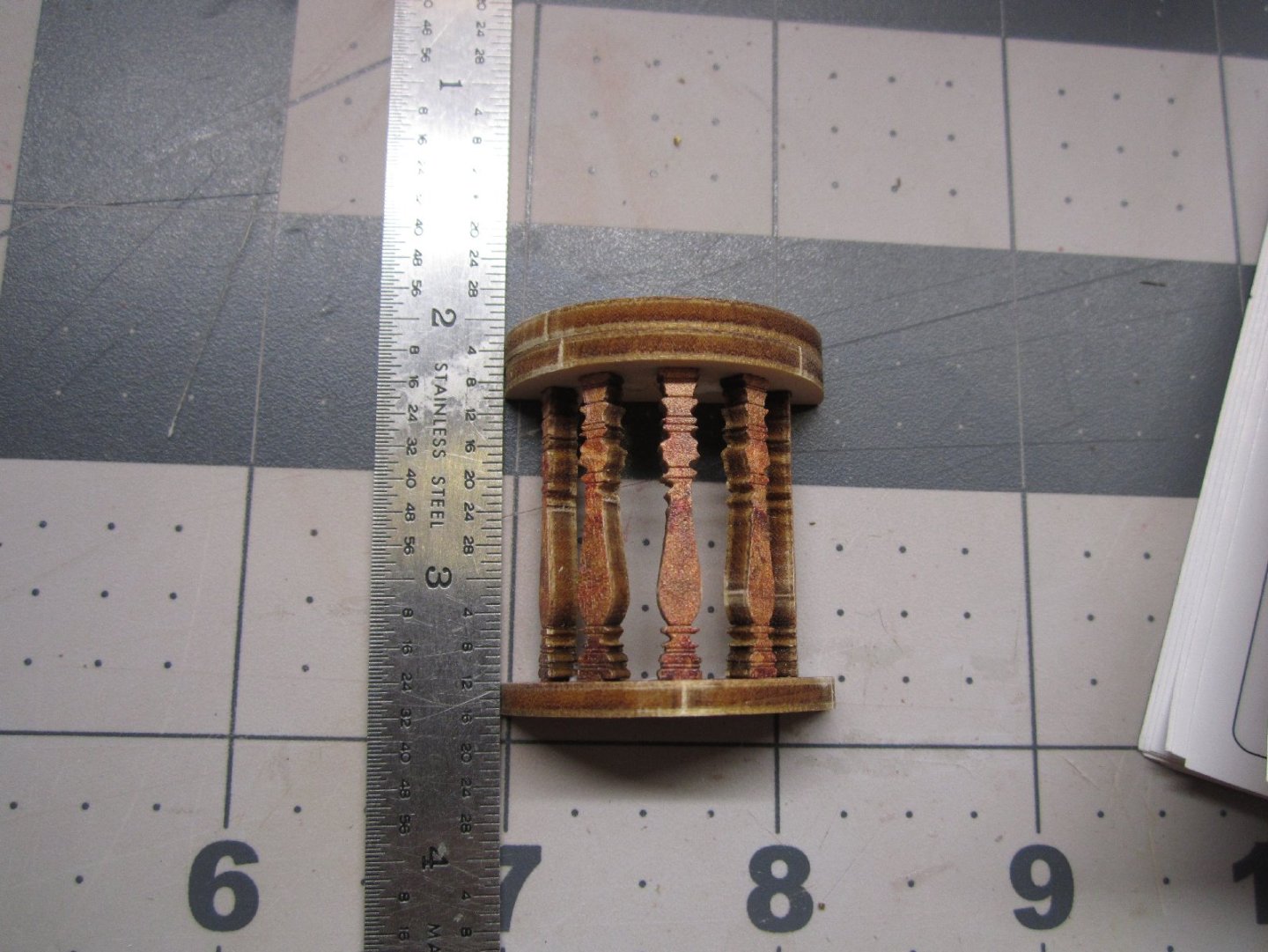
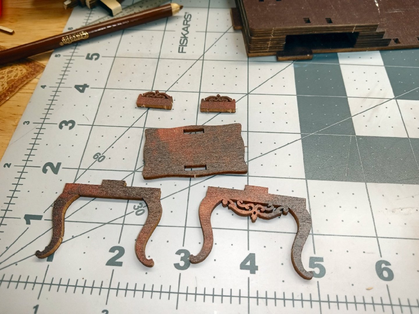
Part 004 While using pencils to color the edges of the Victrola I broke the area of the neck of the trumpet, not all the way, but it was floppy. To fix it I added a bead of glue along the back of the area, and as added strengthening, I glued a sliver of paper to the back between the mouth of the trumpet and the base. After a couple rounds of adding more glue along those areas, the part is now quite strong. After the last layer set, I trimmed the pointed area of the paper off. My acid-free paper came a few days ago, and I eagerly loaded it into my laser printer, to print a new copy of the carpet! I ran the print, with a couple extra, and got a shock when I looked at the prints, they were in Black and White! What the h..l! Then I checked the printer, the magenta cartridge had just run out of toner! AAAAHHH! Not immediately having the money for a new set of toners, (the others were also low), I dug the old prints I did on regular paper out, and sorted through them to find the best two. I took the slightly darker print, and proceeded to set the carpet down like in the trials, I ran in a previous part of the thread, this time gluing the sections down as I went. It went well until I got to the last area that was to go down on the lower level, it was crinkled a bit and bowed up in the middle. No problem, I just laid down glue over most of the area, and clamped it down, as shown below. Disaster! The glue had soaked into the paper, and it looked like the carpet had been flooded with water! I had glued the other areas at the edges only. Luckily, I had not let the glue fully dry, and with much effort, and a lot of strong language, I managed to get that section and the glue removed. I could not use Isopropyl Alcohol on it, as it affects whatever paint the manufacturer applied to the kit parts. I cut the carpet at the corner between the lower floor and the riser for the first step. This left the section on the riser loose, as I had only applied glue to the horizontal areas. I took the slightly lighter print and cut it a little longer than needed, the end of this extended past the front edge of the floor, and clamped it in place. I pressed it in place, with the curved sprue section I used to form the rest of the carpet, then ran a hobby knife down the curved corner. This gave me a guide, to trim the unneeded area off. I moved the sprue back a little and holding it down tightly, after making sure it was parallel to the front edge of the floor, I trimmed the extra off by running the knife down the sprue edge again. This gave me a good matching curved edge. I glued the new floor section down at just the edges, and now, no “water” stains. The two prints are almost the same color, and the difference is not noticeable. To secure the bottom edge of the riser, I held it in place and ran a bead of glue on the outside of the corner. There was a little of the floor showing at this joint after the glue dried, so I painted the corner with Vallejo Flat Earth, which closely matches the tan areas of the carpet. Even if someone does notice the different shades of the two pieces, I will just say that Oriental Carpets are handmade, and even two “identical” carpets will vary a little due to the hand dying process! “That’s my story and I’m sticking to it.” Here is a picture of the finished carpet. Below, is a picture of the small standing picture and frame, that I forgot to get went I took the picture of the hanging frames. I, next, assembled, glued, and clamped the right-hand cover and spine, to the base. Here it is after it dried. You can see the slight gap on the left-hand side of the carpet. Once painted, this disappeared. The next parts I assembled were the back wall area and the first arch. These were supposed to be assembled earlier, but I wanted to wait to glue them in when I had something to support them, in the correct orientation. Before I glued them in, I installed the first LED (see the instructions below), the one that will backlight the window. It turns out the clear stickers are to be used as tape to hold the wires in place. I used one to hold this LED’s wires, and then additionally glued it in place, also. Here is a picture of the LED assembly. The short one at the bottom, is the one that is used here. This photo shows the LED taped and glued in place. The ceiling and first arch make up the rest of this sub-assembly. The picture, below, shows the installed parts. I did not glue the two legs of the arch to the floor. The cover is slightly warped, and the left side of the arch sticks up a little. The arch is captured by the floor and ceiling tabs, so it can float free at the bottom. There are two more arches that go in front of this one, so any gaps will be hidden. I hope everything will meet better when the other cover and the front piece are installed, and can counteract the warpage. If not, I will torque the whole assembly and add glue to hold it in the correct alignment. In the picture you can see the gap on the left-hand arch leg. I wanted to see how the backlighting looked, so I set the left-hand cover in place and turned on the LEDs. The first shows the model with the interior dark, so I could get the whole effect. When the model is done, there will be two more LEDs lighting the interior. The second picture is with some overhead light added. I glued in the cabinet, and clamped the left side, so the bottom, sat firmly down on the floor. The instructions, would have had me gluing a set of books where the head of the clamp is. I’m glad I waited until this was in place. The next assembly, is a small semi-circular table. The instructions have a mistake, that I did not notice, until I went to paint the edges, while building this. In the picture of the instruction sheet, below, it clearly shows the upper level of the table, having both pieces with the printed surfaces pointed up. This unfortunately, leaves the raw wood side facing the interior of the assembly! I had to paint the underside, as well as the edges, to hide this. The table should be built with the printed side of this piece down. You can see the raw face in the picture below. It was “Fun” trying to get all the spindles in place while attaching them to the semi-circular ends, and that is one reason I missed the error. In any case, once everything was assembled, I use the edge of my ruler to line the top and bottom of the piece up. In the next Part I will be building some of the small details, including the books.


-
Who made this kit? I have the model Expo single mast version.
-
"Sailing Memory" by thibaultron - Book Size Diorama
thibaultron replied to thibaultron's topic in Non-ship/categorised builds
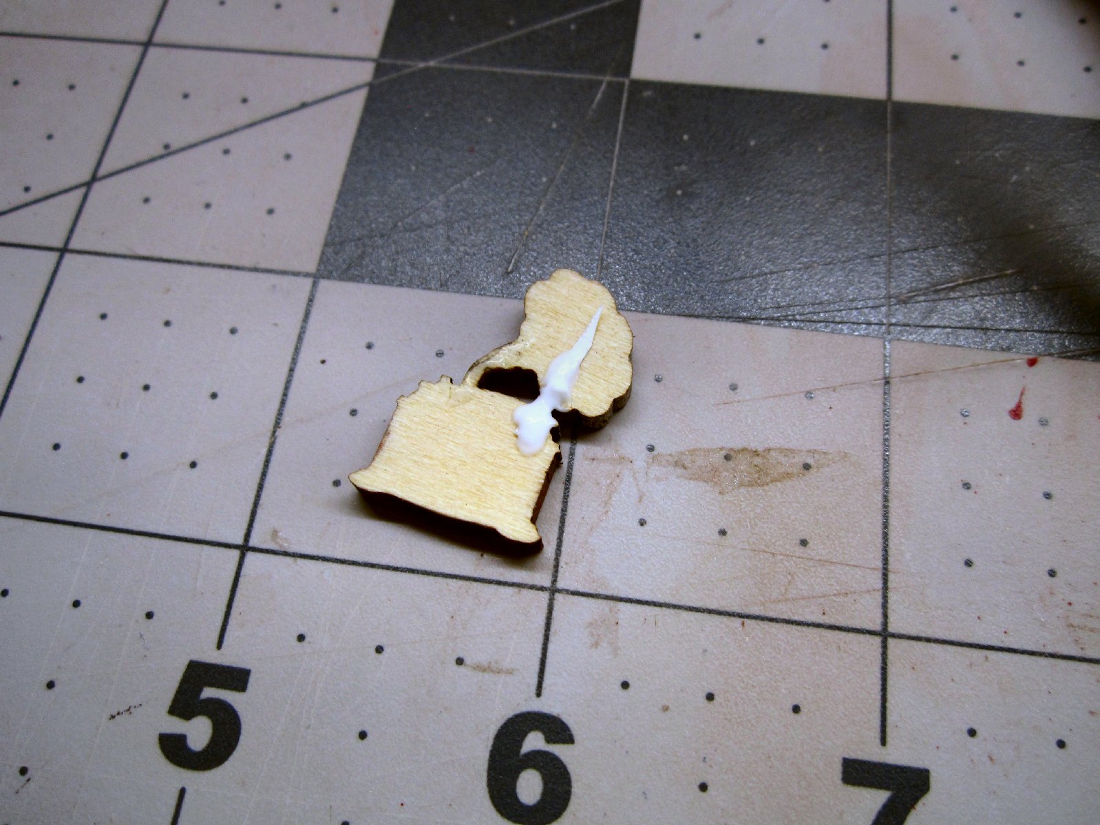
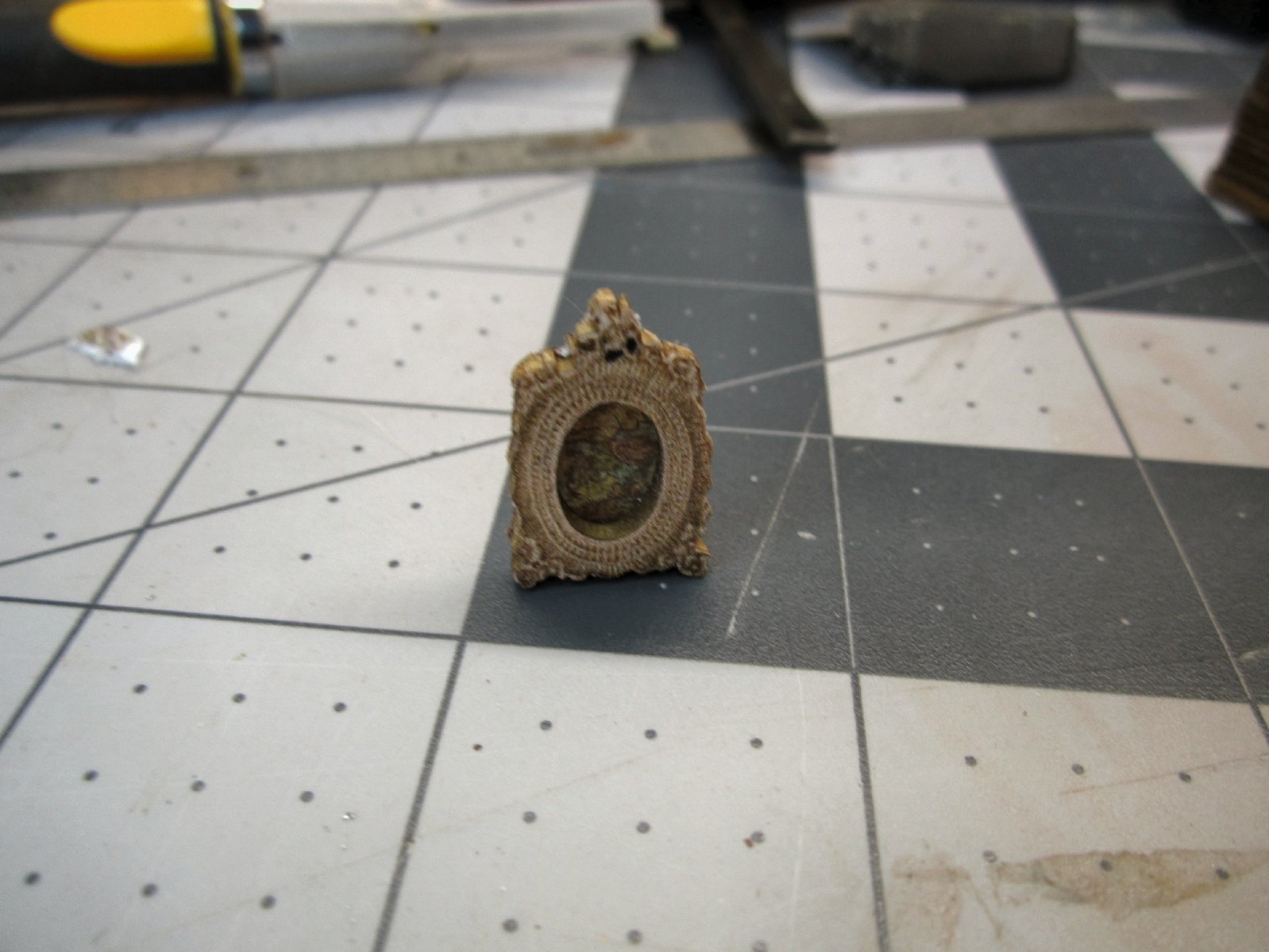
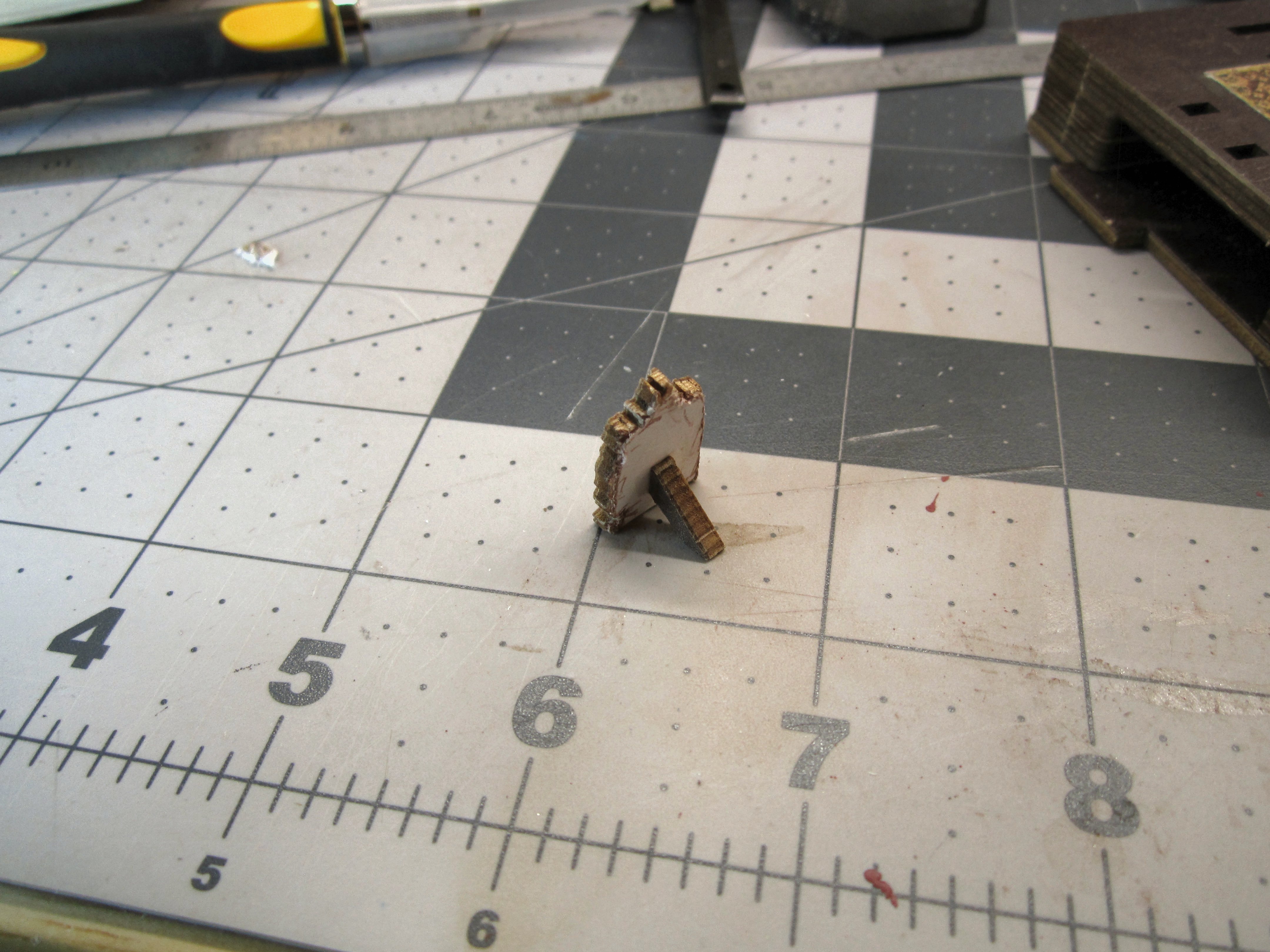
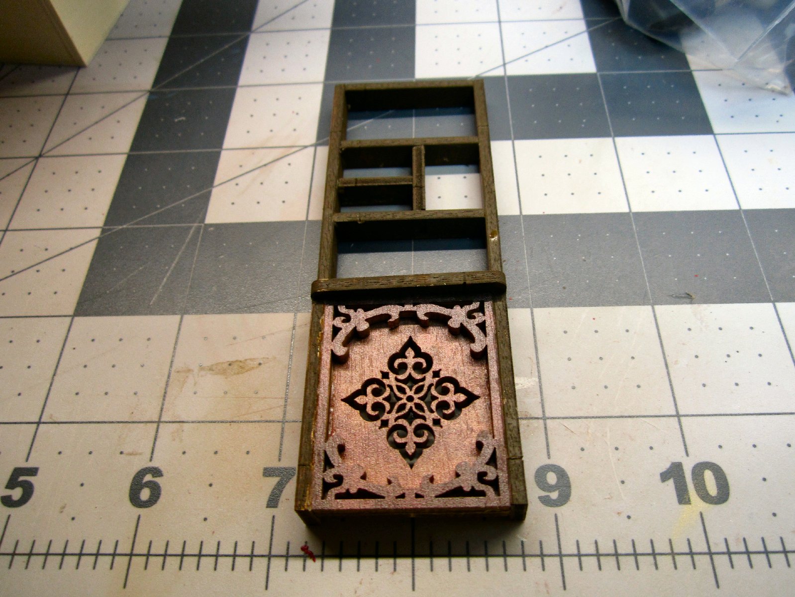
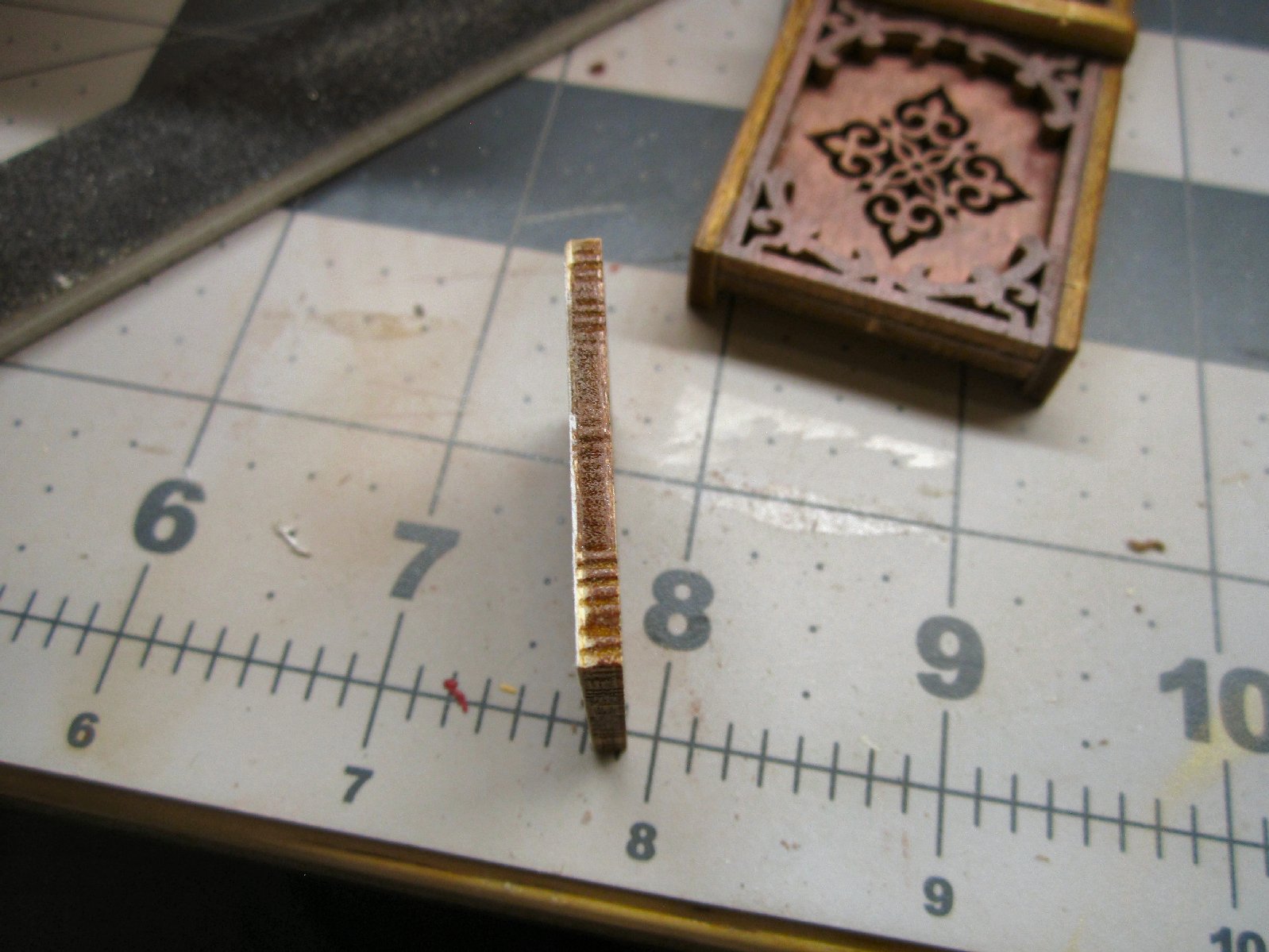
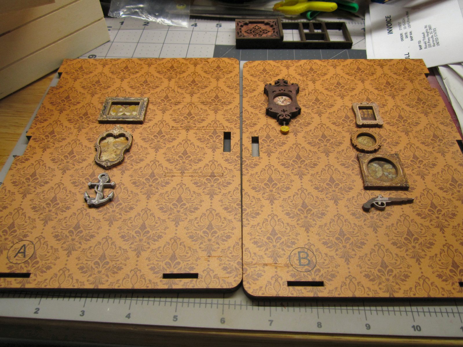
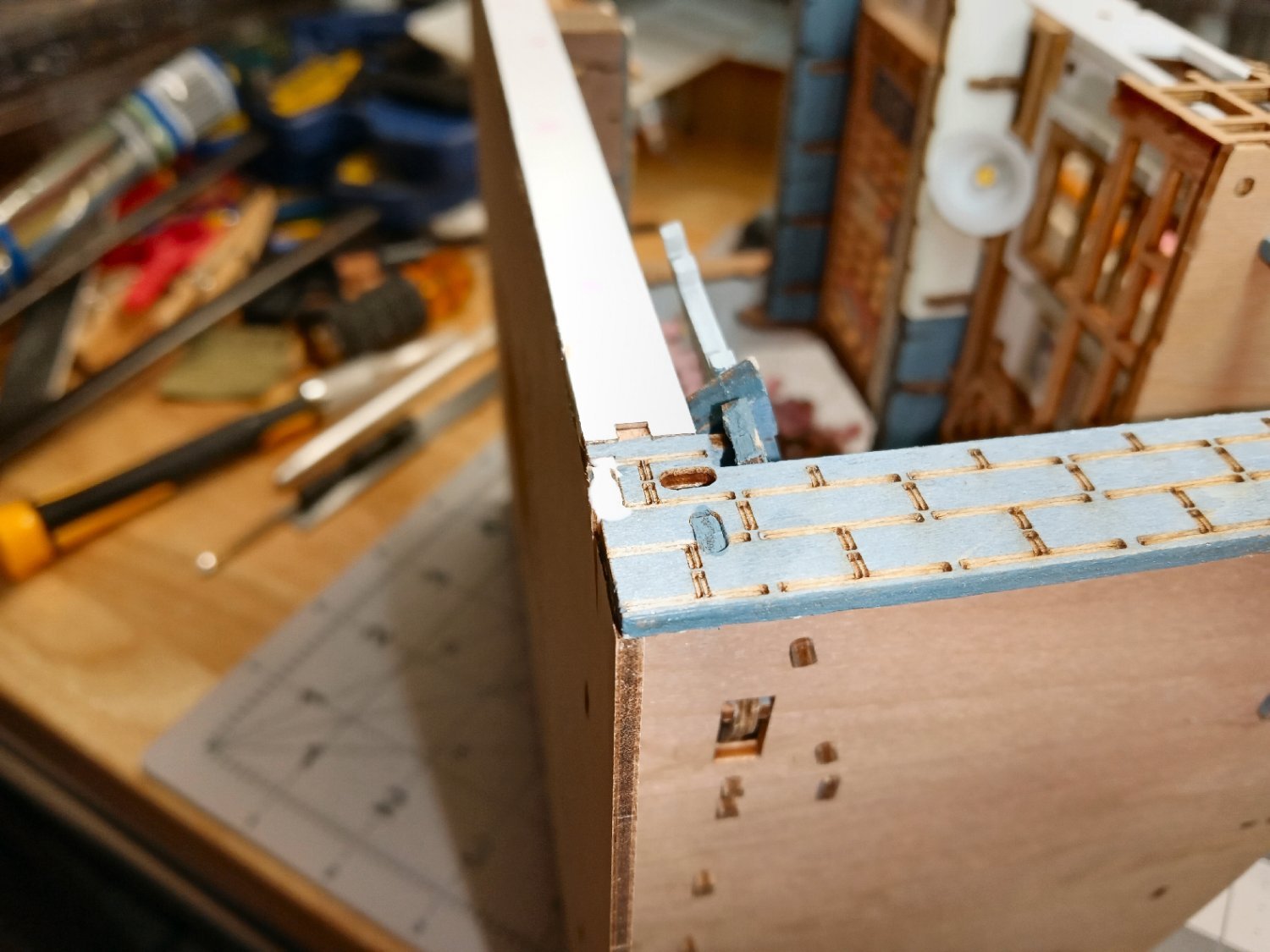
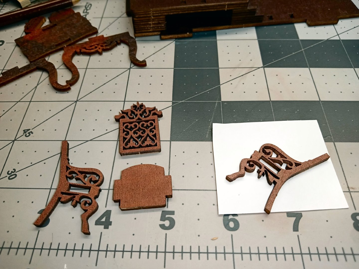
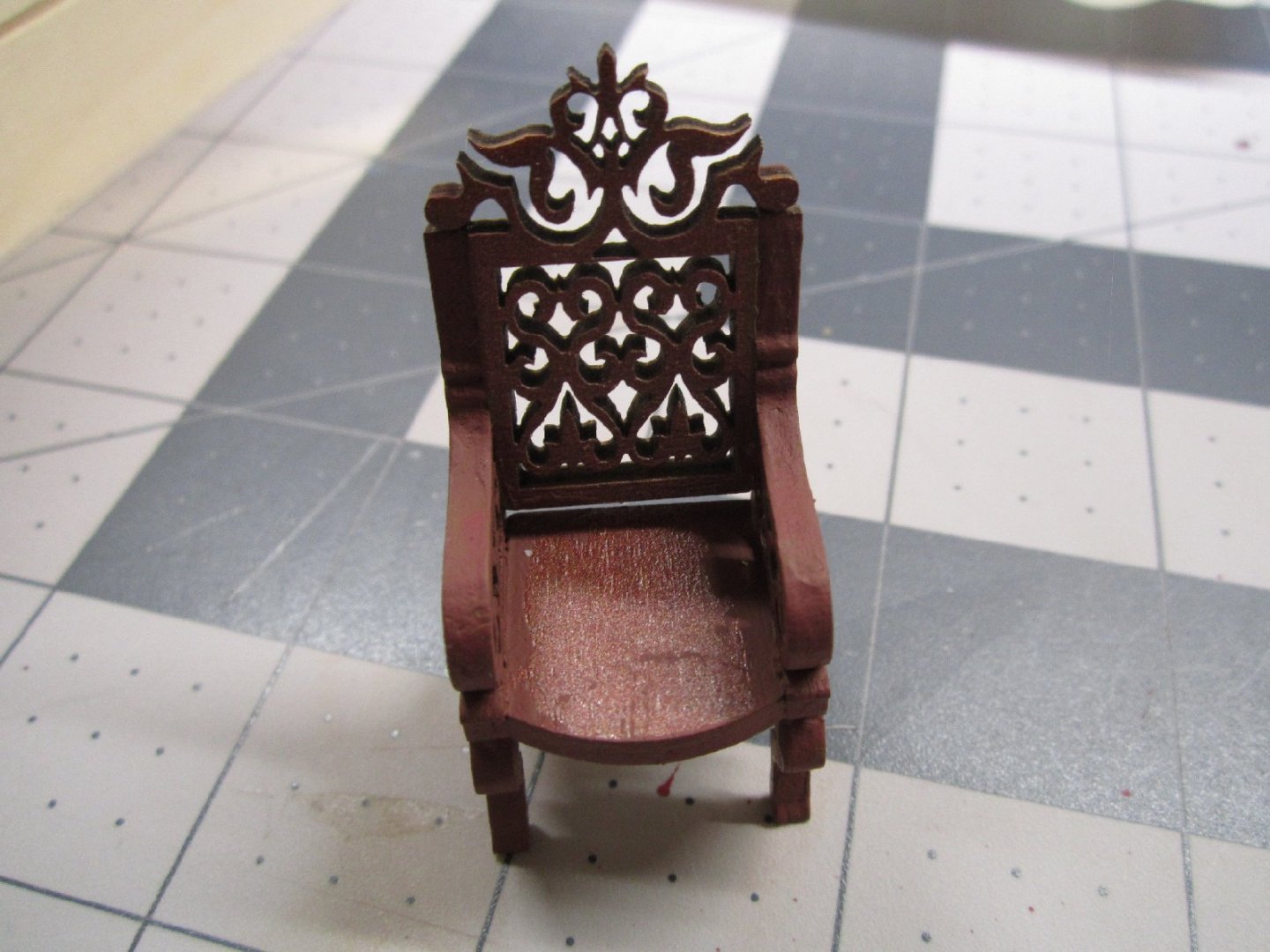
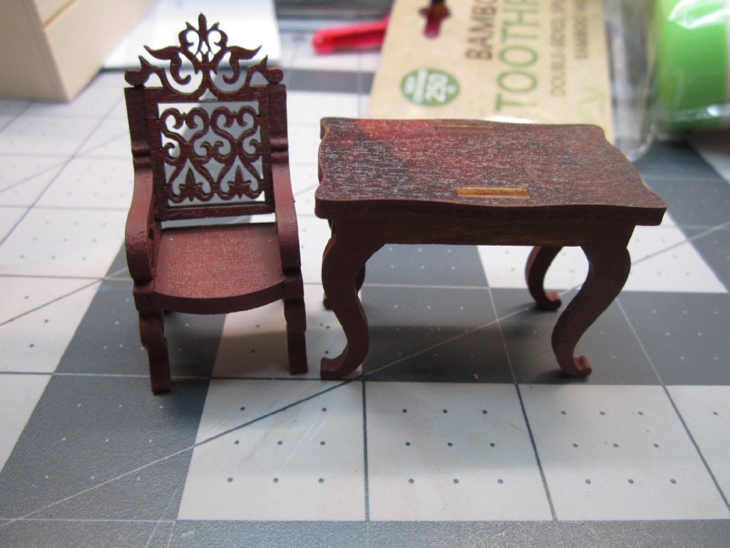
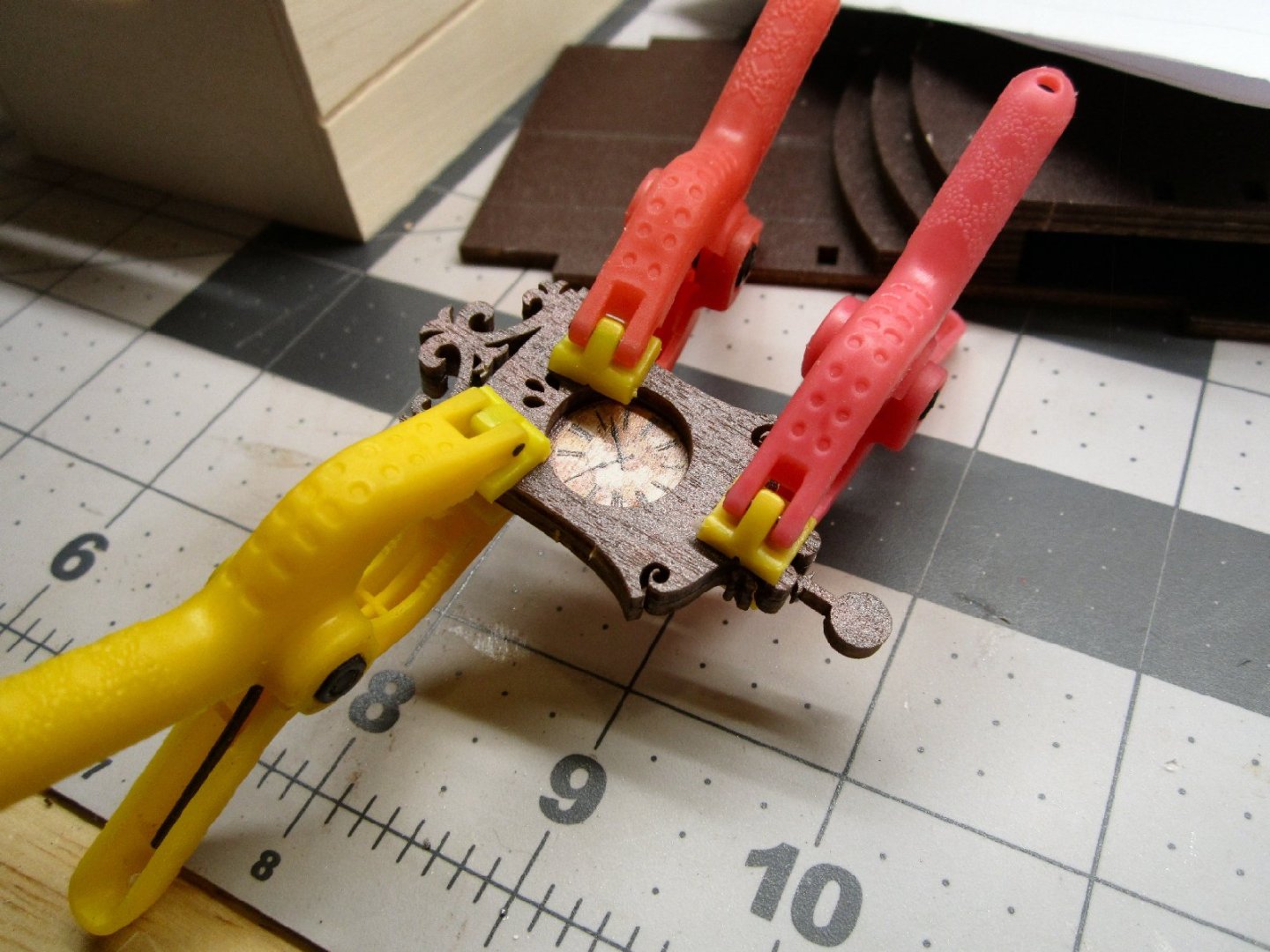
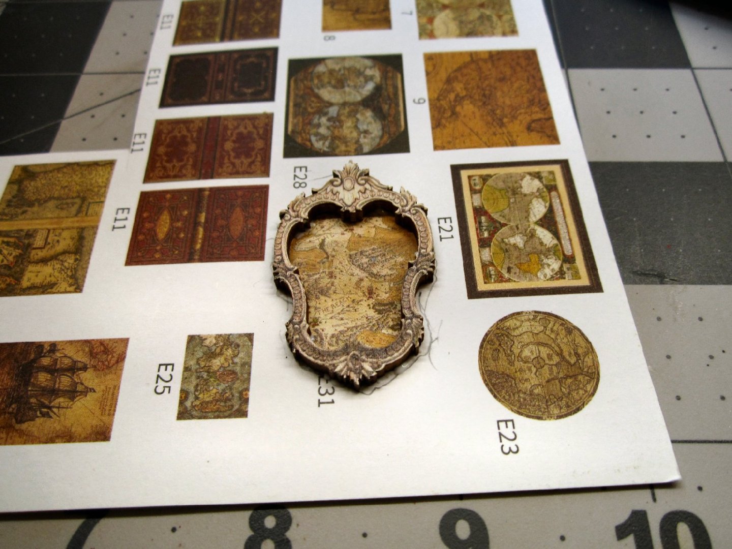
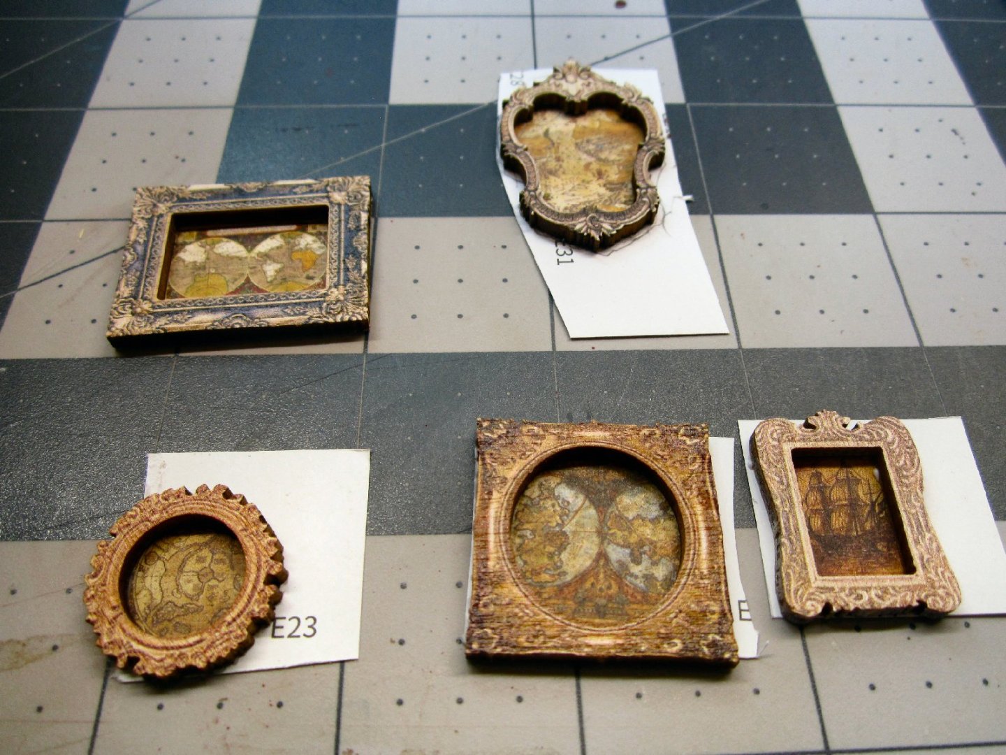
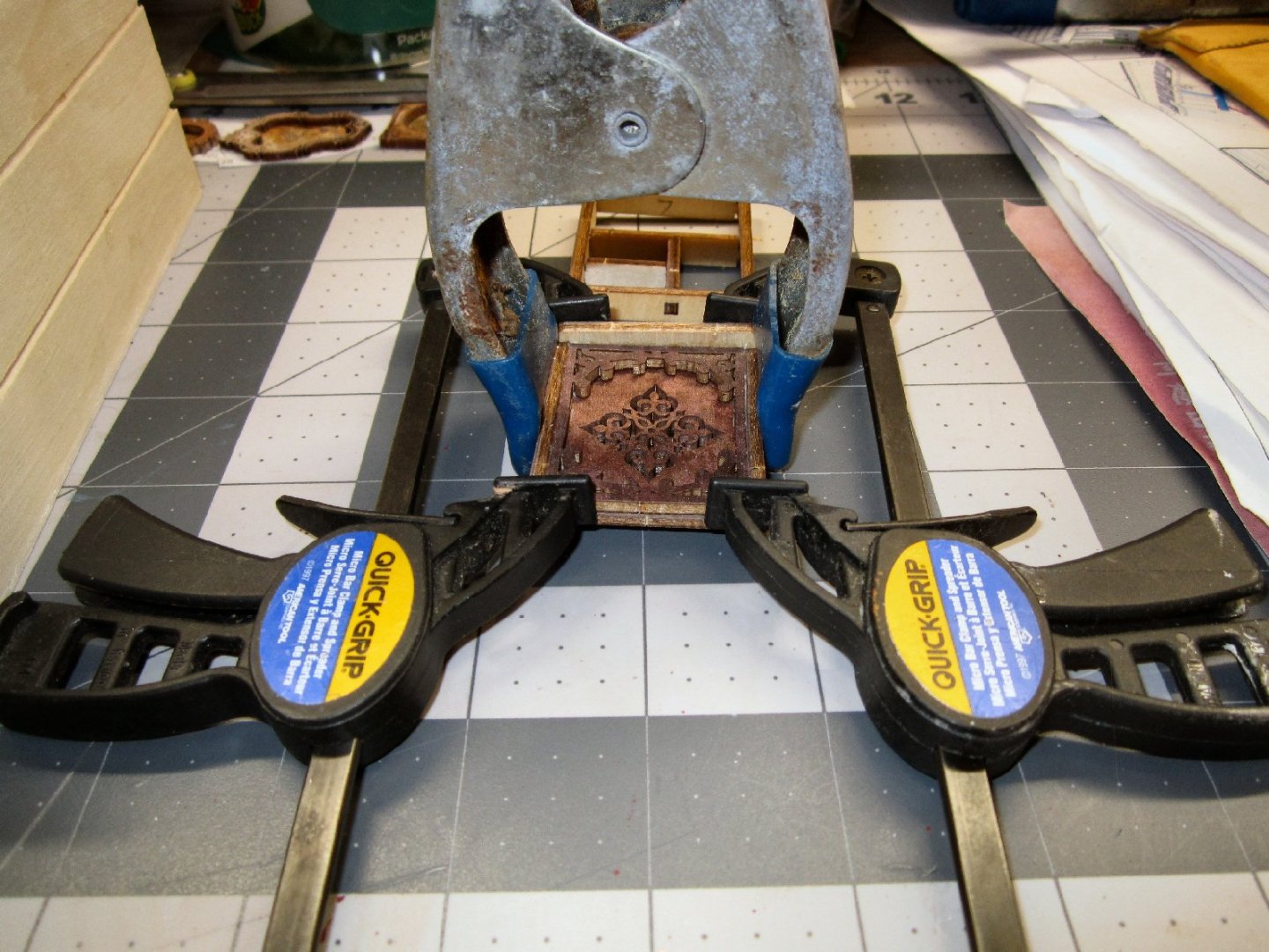
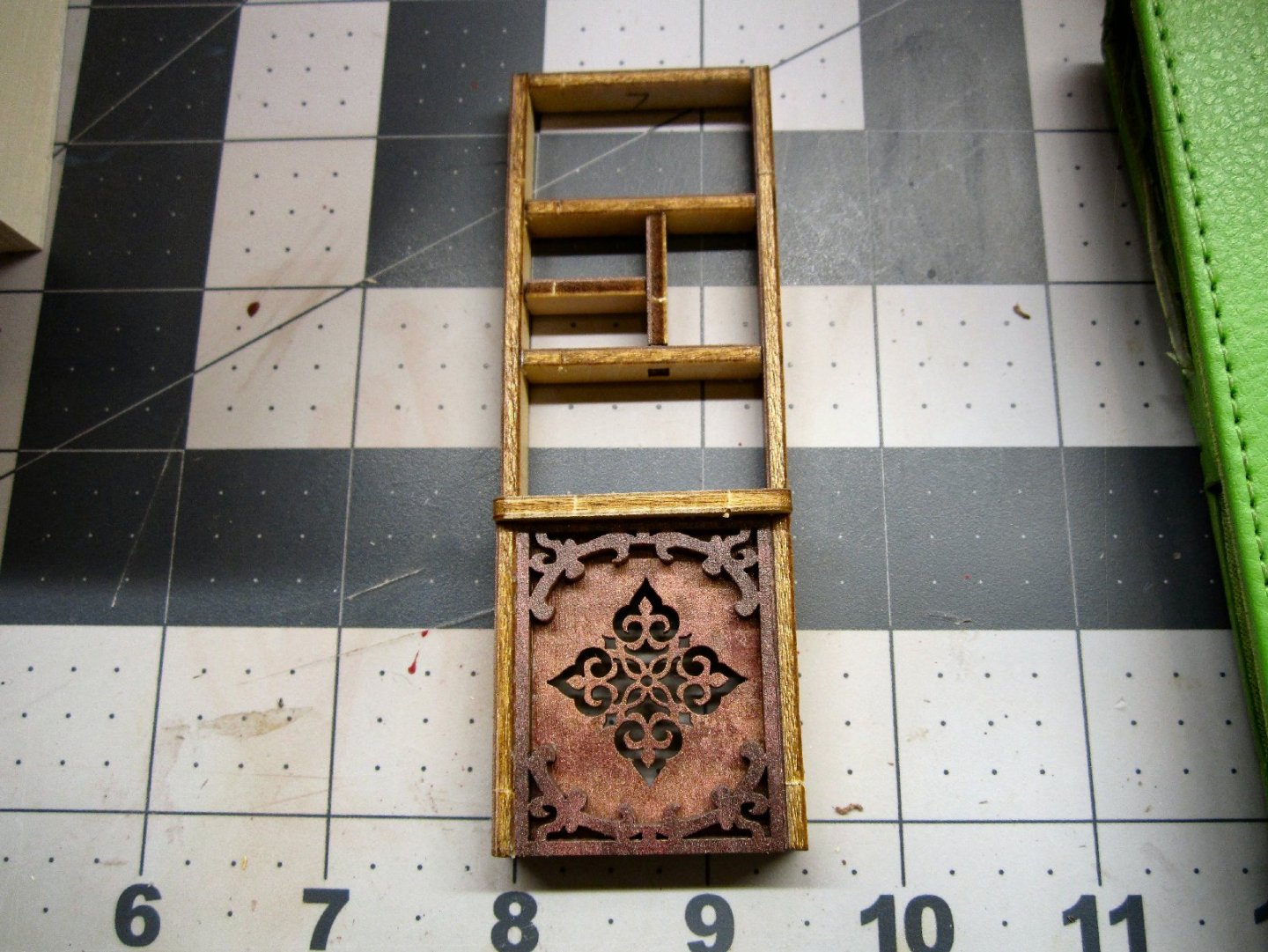
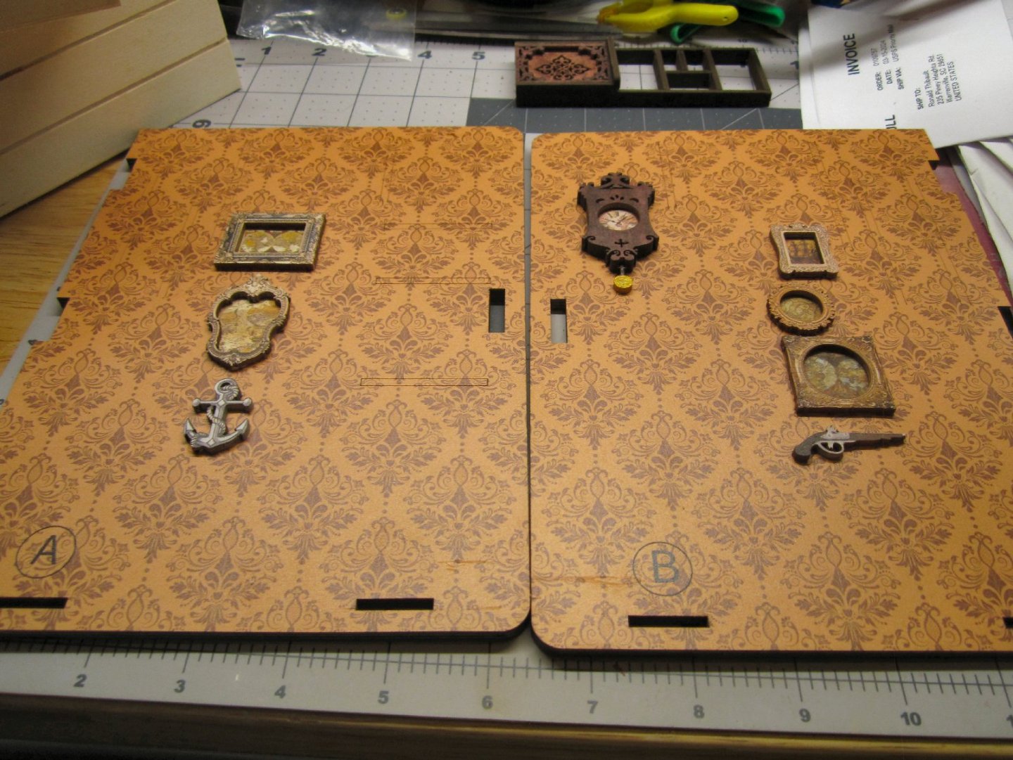
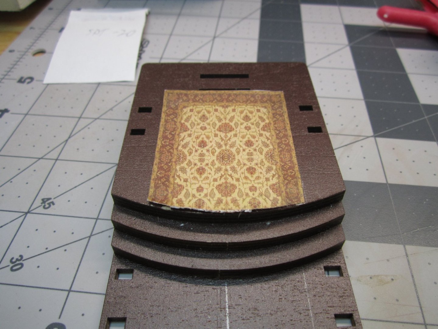
Part 003 There are several different colors for the parts of this kit, as opposed to the previous two I built, so more matching was required for the edges of the pieces. I used a combination of colored pencils and Vallejo paint to hide the plywood edges. For small pieces like the picture frames, items on the shelves, etc., that had multicolored fine detailed surfaces, I used the pencils, to avoid marring the surface detail with misplaced brush strokes. The small items are going to have most of the edges hidden by other details or viewing angles anyway. For the larger items I used the paints. Below is a picture of some of the early paint trials, using different shades of Vallejo Brown paints to find a close match. I tried Burnt Umber, Heavy Brown, Flat Brown, Chocolate Brown, Flat Earth, and Light Brown paints. The burnt Umber matched most of the edges best. Two items were a royal pain to match, the chair and table. They had a multi colored mahogany woodgrain pattern! The two pictures below show the parts for each. In the end I had to settle for a mix that somewhat matched, and did my best to keep the paint off the pre-colored areas. One saving grace is that the tabs that will be so prominently displayed on the table surface, will be hidden by a printed map. In the end I did a decent job on the edges and unprinted sides of the table, but ended up painting all but the printed area of the seat and the chair back. Most of the lower chair will be blocked by the table either directly, or by its shadow. The paint mixture I ended up with was 10 drops of Chocolate Brown, mixed with 4 of Red. The brown was a little runny, and the red thick, so your results may vary. The red paint was the first one I’ve come across that was too thick, at first, to just use a mixing ball to “stir”. I had to remove the tip and stir it with the broken off end of a wood Q-Tip stick, as well as pulling the stick out and wiping the blob, on the side of the bottle. After getting it mixed this way, the ball then finished the mixing. This bottle came from the first set of paint I bought about 6 or 7 years ago, so the age may have been a factor. The blue that came out of the same set did not exhibit this problem though. Here is a picture of the painted chair. And the completed set. The next part I built was the clock. It consists of two pieces the back with the dial printed on it, and the front. The edges of the completed piece were too complex for a pencil, so I used a brush and Burnt Umber to color it. I carefully wiped up the little bit of excess paint from the front. I should have painted the inside of the cutout for the dial, but did not think of that until after the two halves were already glued. I also painted the pendulum weight brass, as, what self-respecting Sailer would not keep his brass polished! In the end, this part is going to be mostly hidden by arches, but I will know its there. As a clock fan I wish it was more prudently displayed, but I had already glued the pictures in the designed prominent areas, before I discovered that the clock was going to be hidden. Next, I worked on the pictures. The best way I could think of attaching the printed pictures to the back of the frames, was to glue the frames directly to the sheet, and then remove the excess and carefully clean the many fine edges as best I could. If I had precut the pictures from the sheet, I did not think I could get them centered properly, without getting glue on the surface, of the print. This method took a lot of clean up, but I think it worked out better. The picture below shows the first frame being glued on. The pencil marks are from my first trial to see if I could cut out the complex edge first, and then I decided the way, I ended up doing it was a better option. One mistake I made was not paying attention to the clearances between a frame and the pictures near it. For picture E21, when I glued the frame down, the frame partially obscured the print for E23. Luckily there was just a small gap left when I glued on the frame for E23, that is hidden by the viewing angle. After that mishap I cut out the individual pictures, leaving as much white surround as possible, and then glued the frames to the individual pictures. The picture below shows the frames glued to the matching pictures. There is a smaller frame not shown in the photo above, that fits on s shelf, that I also glued up. The next assembly is a shelving unit, that will hold some of the small items. It has the frame and shelves, with a two-layer bottom decoration. I cleaned up the parts, glued them together, and clamped everything as best I could. The next two pictures show the glued and clamped shelf. Here is the completed shelving unit before I painted the raw plywood edges and back surfaces of the vertical uprights. I used Burnt Umber to paint the surfaces. I next cleaned up the picture frame edges, with a hobby knife, files and sandpaper. This left the paper edge and sanded wood areas, which I colored with pencils., as show in the fuzzy pictures below, sorry. Then, I glued the pictures, clock, and some other decorations to the marked locations etched on the interior walls. Construction will continue in the next part. The acid free paper arrived today, so I can start working on installing the carpet, also.


-
"Sailing Memory" by thibaultron - Book Size Diorama
thibaultron replied to thibaultron's topic in Non-ship/categorised builds
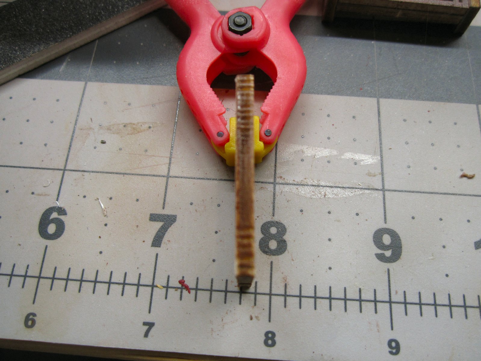
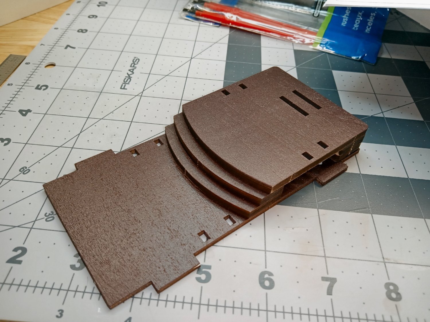
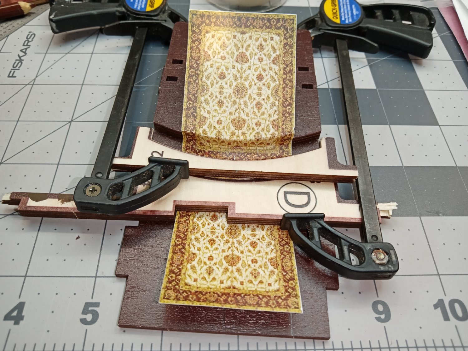
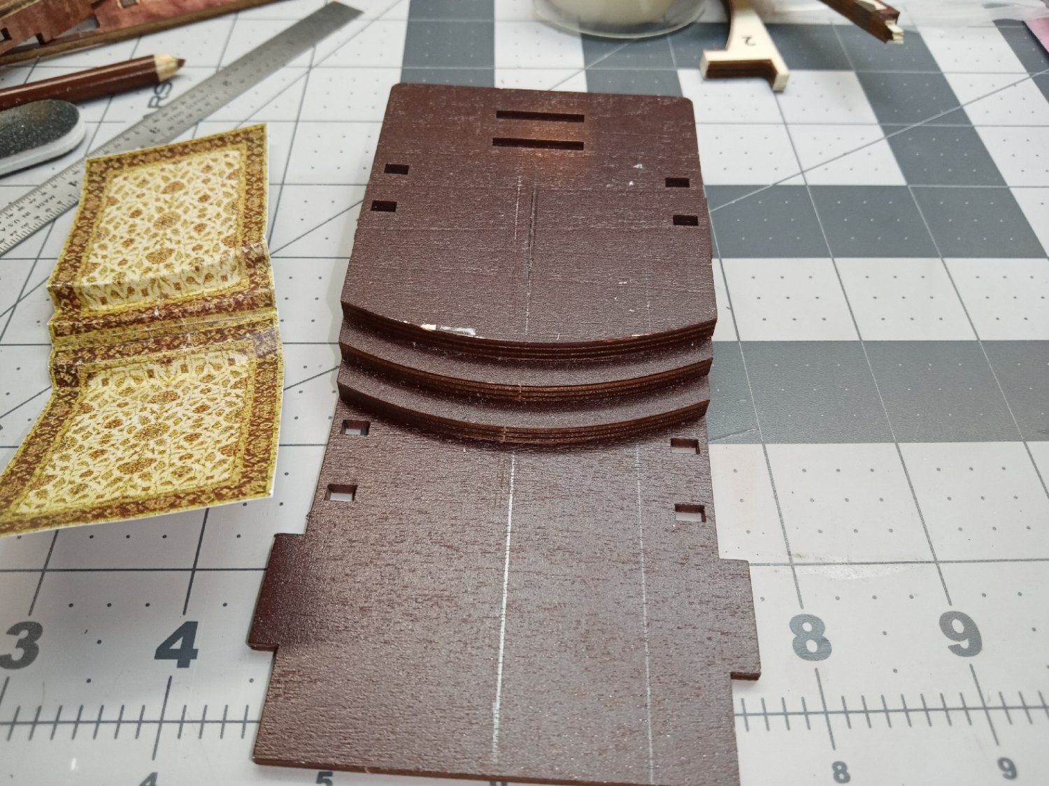
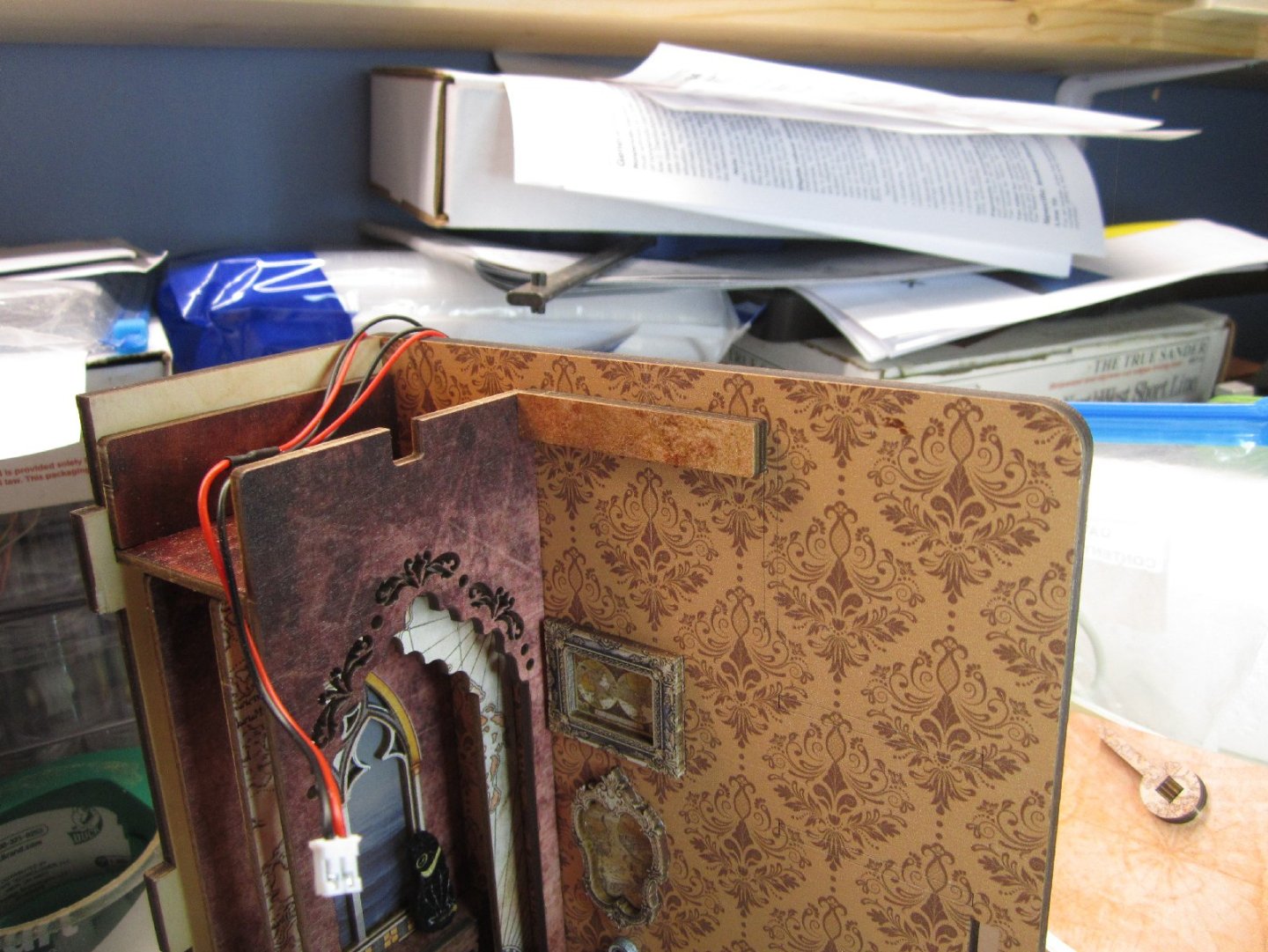
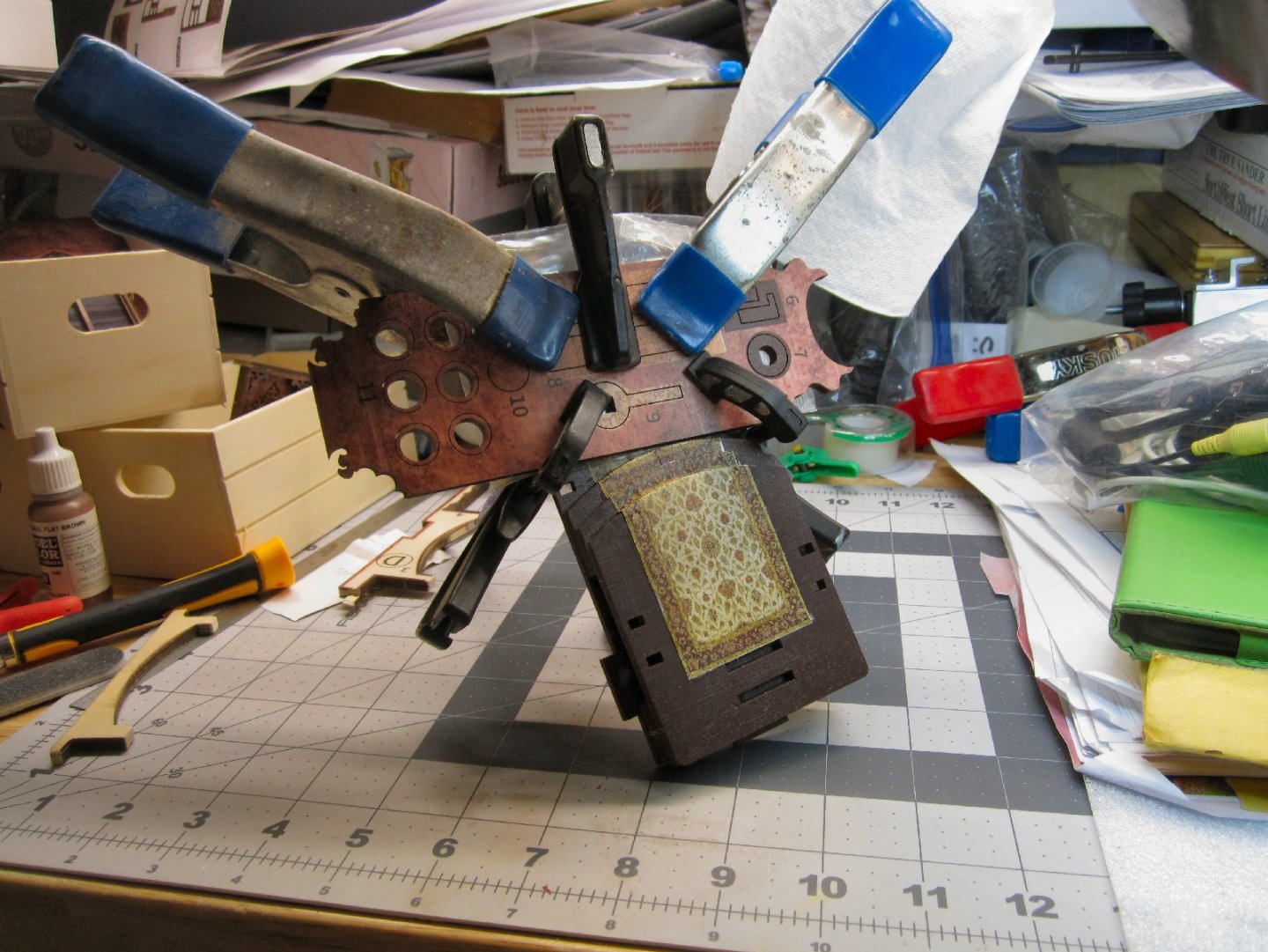
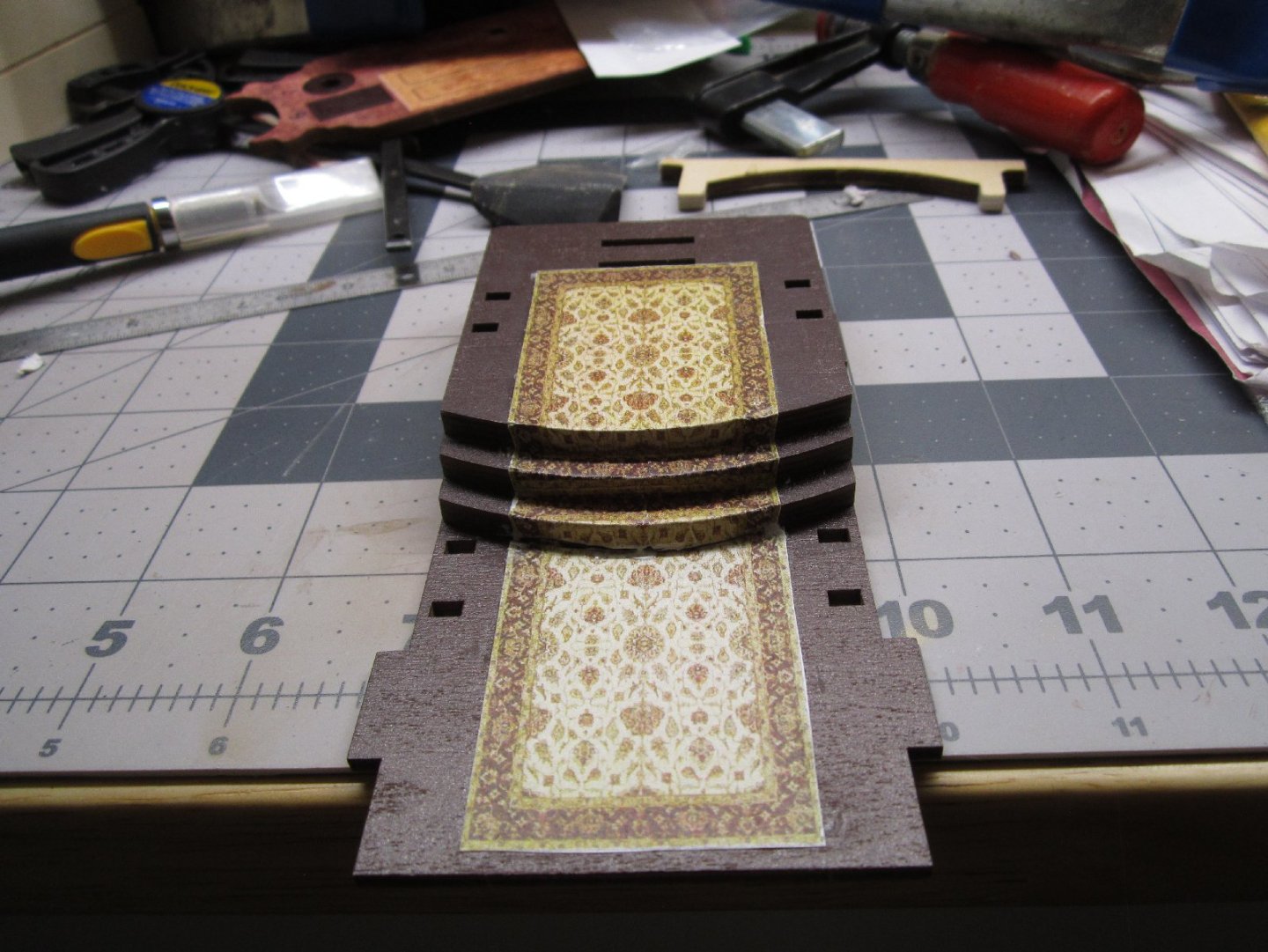
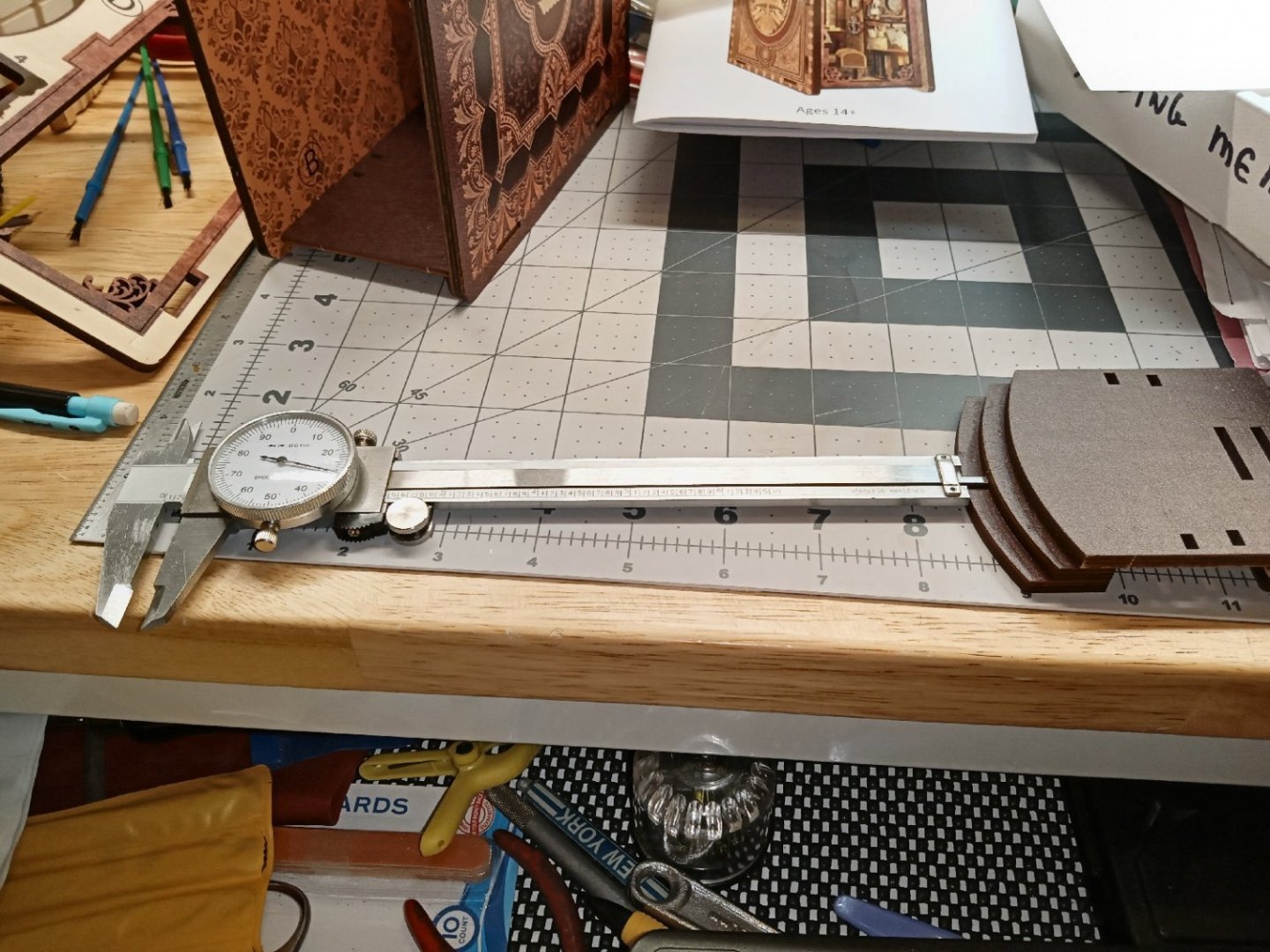
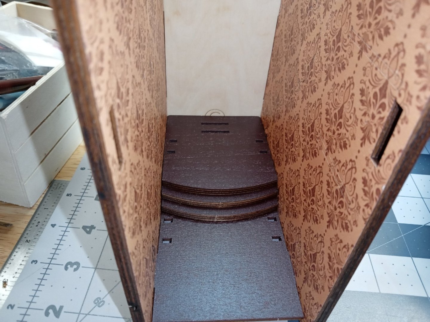
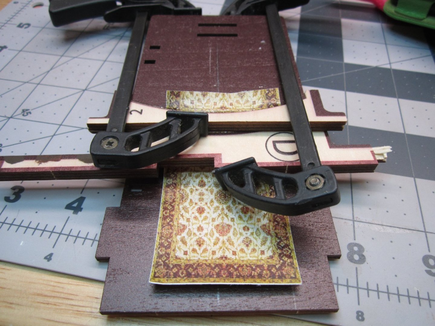
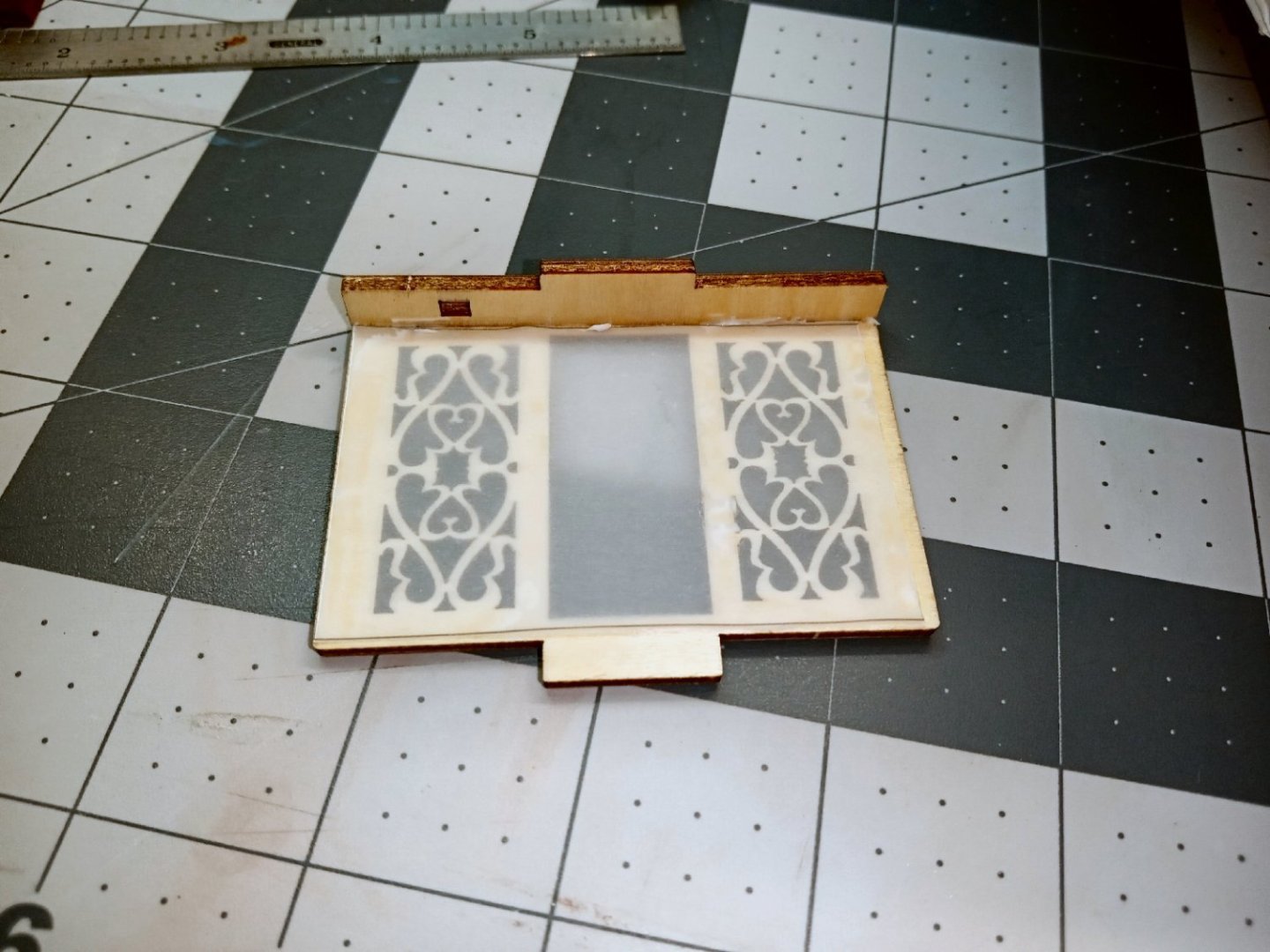
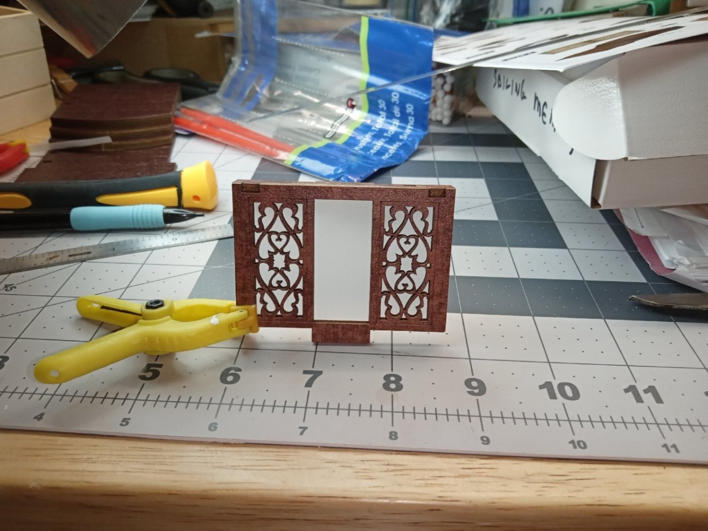
Part 002 The first part in the construction is building the floor/base of the diorama. The back of the floor is raised with three steps up to that level. Two blocks are glued to the underside of the rear of the raised floor, making sure the back edges of the parts are even with each other, as well as with the sides. The steps, like the rear blocks have two pieces that are glued with the back ends even with each other. There are, however, no locating marks on the underside of the raised floor to guide attaching the step block to the floor. I used my calipers to measure the depth of the step on the block, locked it and used then used the caliper to set the depth of the step block to the floor section. I measured radially at both ends and the middle. I also made sure the edges matched the floor. To make sure the floor fit properly in the case, I temporarily assembled the book cover pieces, and set the floor in. After taking the floor section back out, the next step in the instructions shows the carpet from the detail paper sheet being installed. The problem is the carpet is all one piece, and the instructions show it flowing continuously down the steps, which are curved! Simple for a real oriental rug, which will stretch somewhat, but a bit harder with a sheet of paper! I could not figure out how to do this, so decided to glue the carpet down on the raised section, then trim it off even with the curved edge. Mistake, I then realized that fitting the remaining sections down one piece at a time would be a nightmare! Luckily the carpet was printed on the sheet as two pieces, and the other matching section was intact. I scanned that piece in, and doubled it to create a new complete rug piece. I was totally unable to completely color match to the old piece, but I came close enough to remove the old section, and will use the print to replace the whole thing. To print the carpet, I’m using a laser printer, as my inkjet one died. This presents a couple of problems. The first is that my printer has a maximum print resolution of 300X300 DPI, some of the detail will be lost. Not that the printing on the detail sheet was photo quality anyway, but it is still better than what my 20-year-old laser can do. For this use, and at a typical viewing distance, it will be “Good Enough”, though. The second problem is the toner on the paper has a semigloss finish, not flat like a real rug, and also flat like the other parts on the paper sheet. I lightly brushed on some Vallejo matt varnish, and that killed the shine. The problem still remained, of how to get the continuous piece to mold to the steps! I let the project sit a couple days, and then a light bulb went off in my head! I cut the plywood sheet the parts had come from, and there were two nice forming blocks that matched the step curves. I tried it on the remaining piece of the original rug, and it pressed the carpet down nicely! I started at the top step, clamped the thinner curved section down, then clamped the thicker one below it, also pressing the piece in. I then moved the two formers down, the thinner one to hold the paper in place where it had already been formed, and the thicker on to form the bottom step. I wanted to make sure the carpet piece would fit all the way the length of the lower floor, and it did. The picture below shows the finished test piece. There is a little bit of excess “rug” at the corners of the curves, but it is not as noticeable as raw paper edges would be. I don’t want to use regular paper stock for the carpet, but I’m out of the acid-free stock I had. I’ve ordered three more acid-free reams, and will wait for that to come in, before printing the final carpet piece. I was just going to order one ream, but one was ~$19, and three were ~$29, both with free shipping, so I ordered the three-ream bundle. That is more than I’m ever likely to use, for modeling, but at least I’ll never need to order any more. The next steps are to build the back wall with the cabinet, and fancy window. Here are the three wood pieces, for that assembly. First you glue the translucent backgrounds to the back of the cabinet front, and window unit. I set the glue toward the outside edges, so no glue would mar the soon to be backlighted areas. The picture below shows the cabinet front with some light coming through. Next, I dry fit the parts, to see what it will look like. For now, I am leaving them this way. When final assembly starts, and I can make sure everything lines up correctly, I’ll glue them in place. This pictures how the back wall as it will look like in the finished scene. There are details to glue to the top of the cabinet, but you get the idea.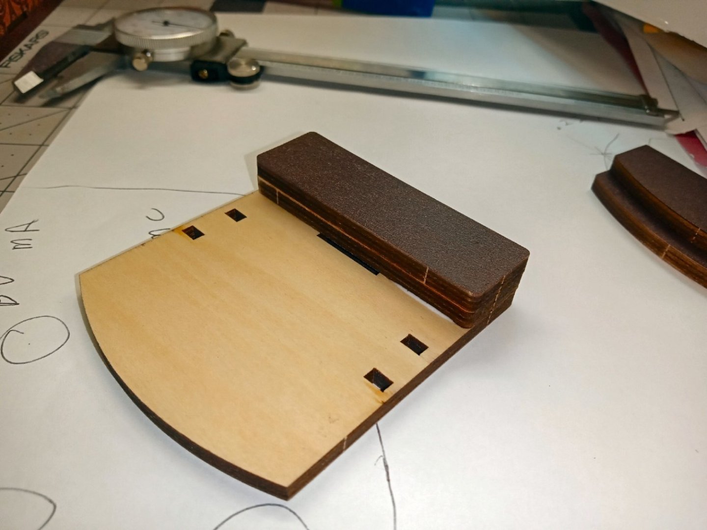


-
"Sailing Memory" by thibaultron - Book Size Diorama
thibaultron replied to thibaultron's topic in Non-ship/categorised builds
I just came across a picture of the cheap kit I mentioned in Part 001. The sad thing is, that it was only a little cheaper, but only showed a picture of a completed model of the one I'm building now! So a Chinese rip-off of a Chinese kit! Notice the white LED module, which had no way to hook up a battery, and the solid amber rubber "thing", that I have no idea what it is for! There were no instructions.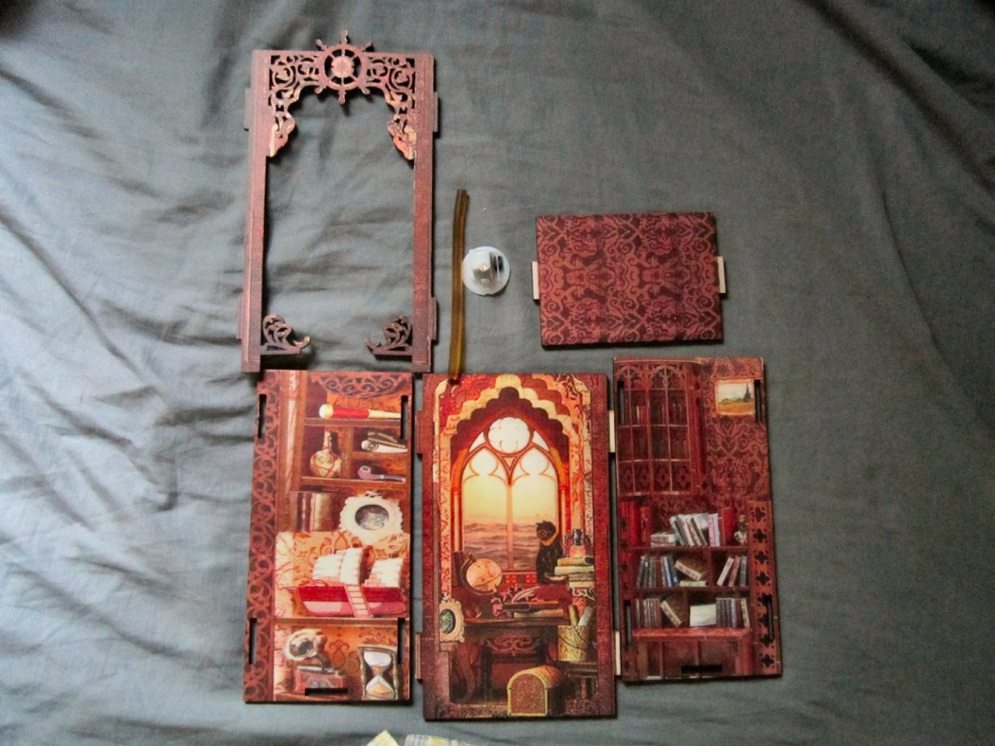
-
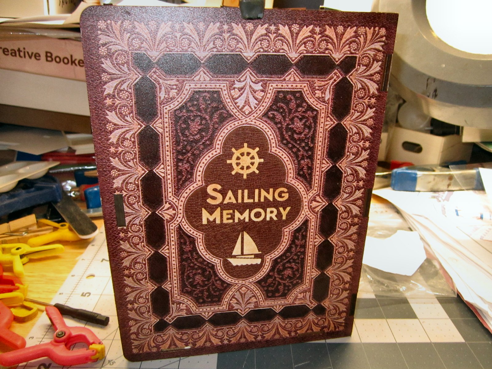
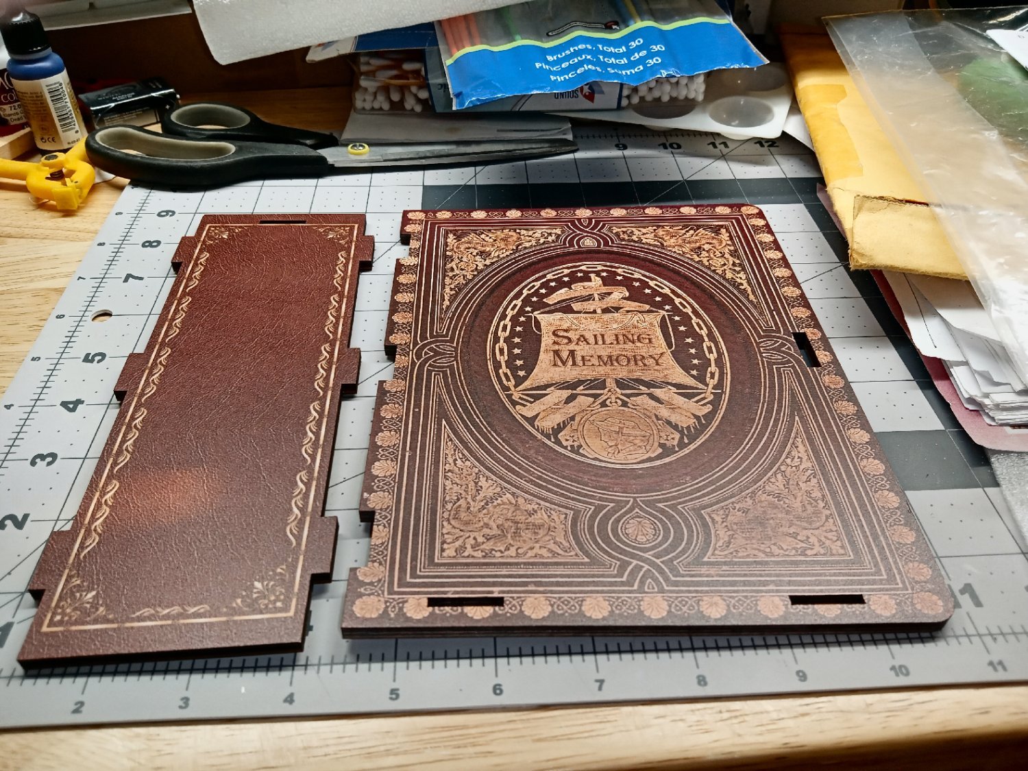
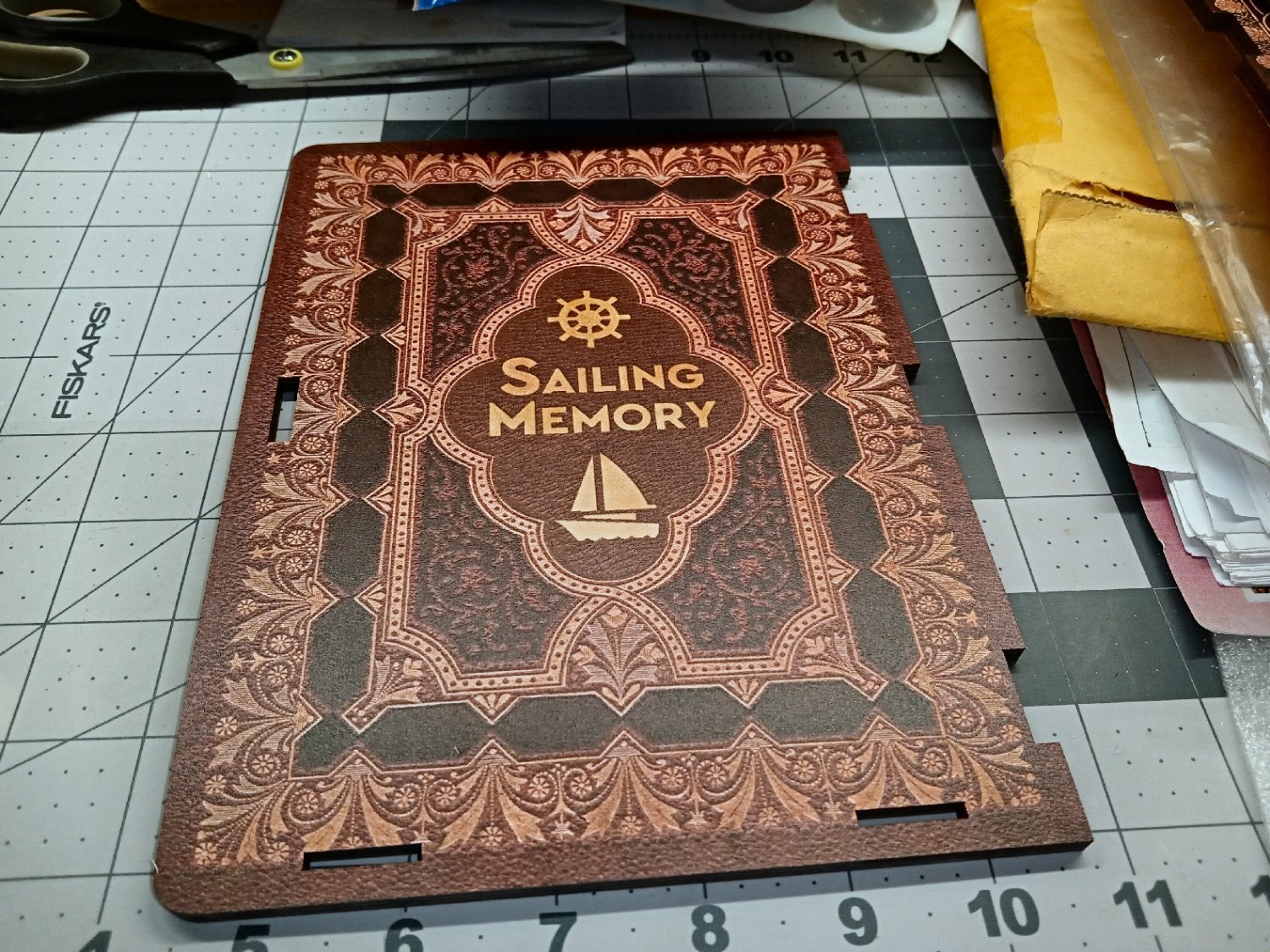
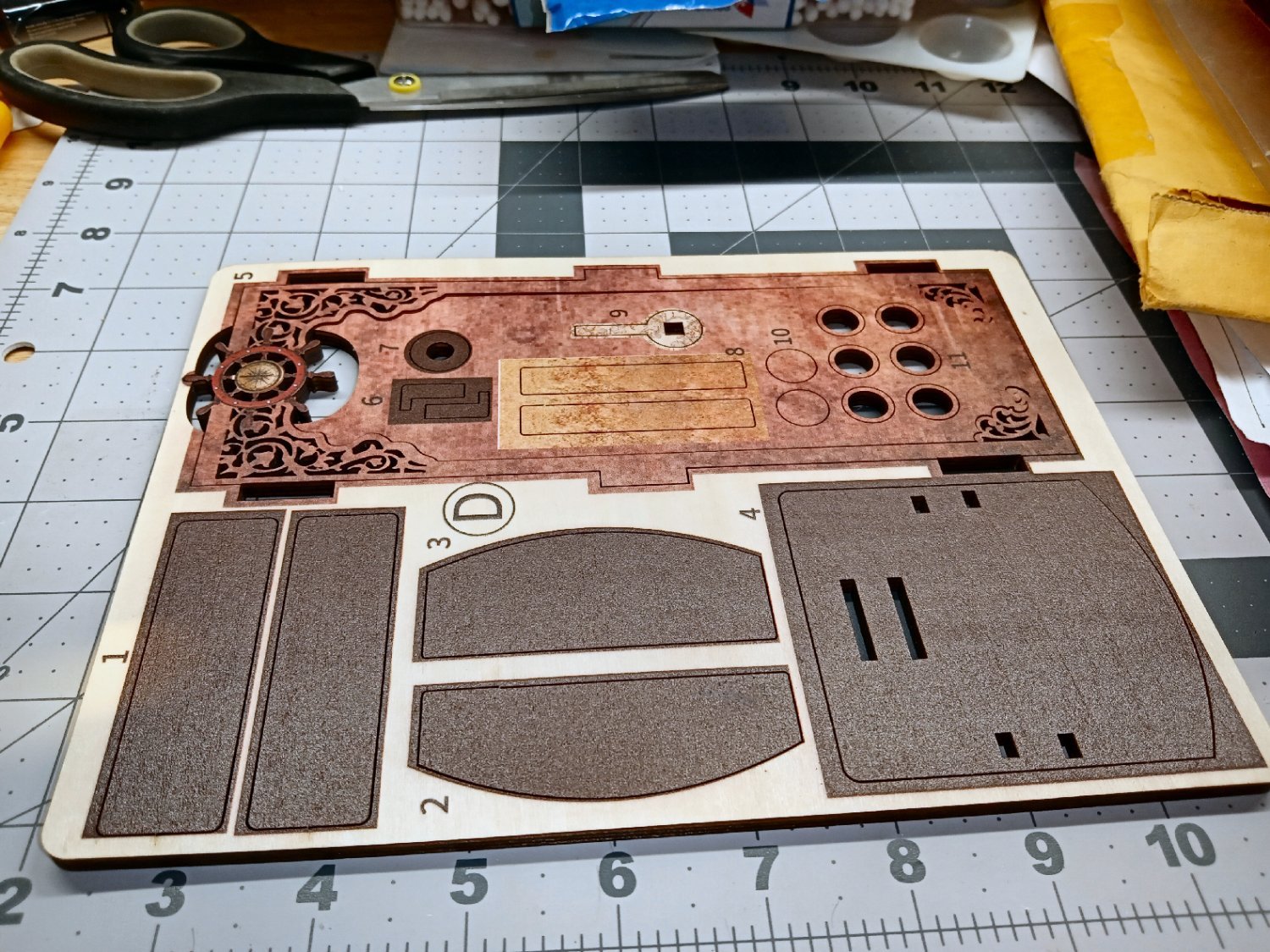
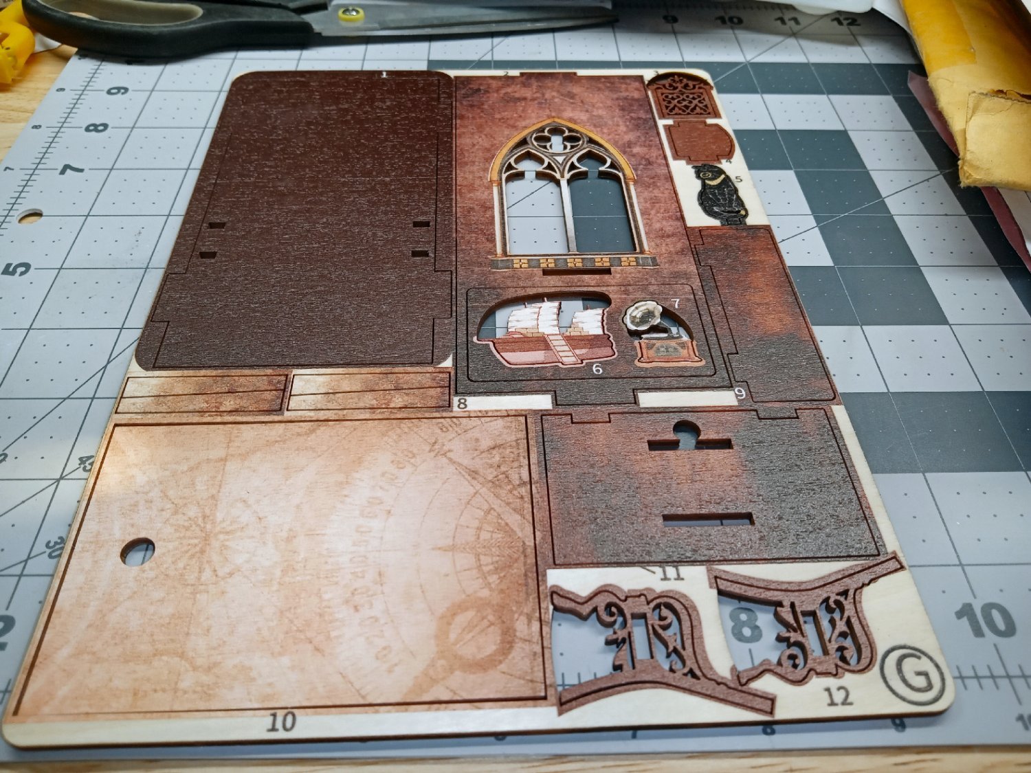
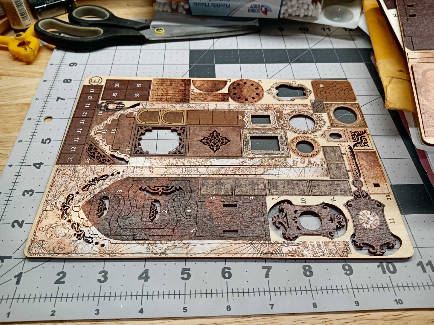
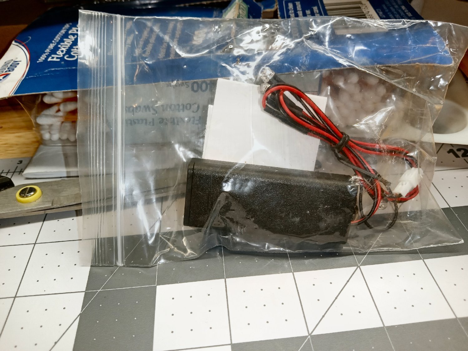
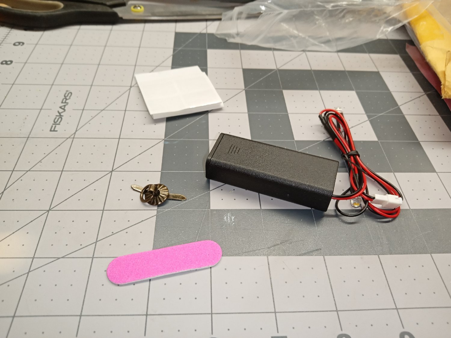
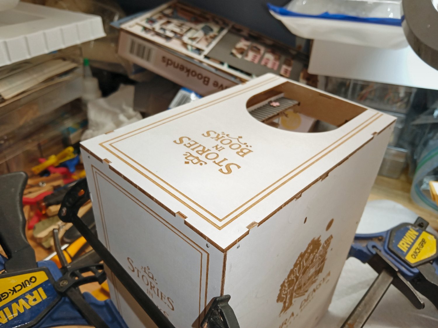
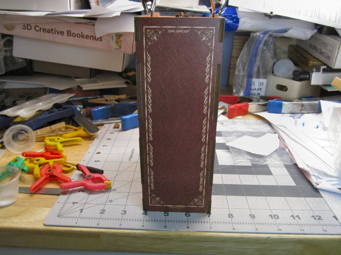
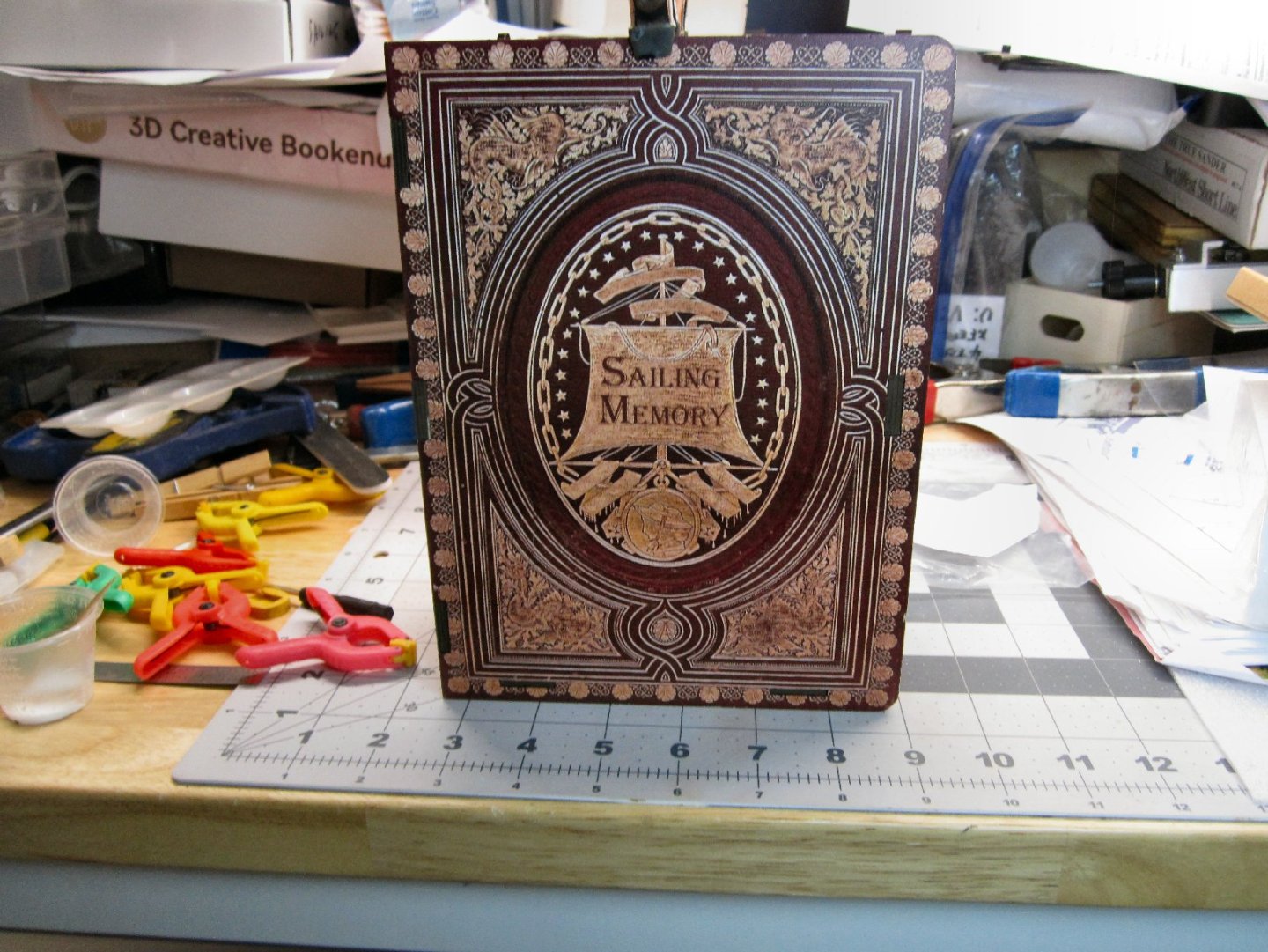
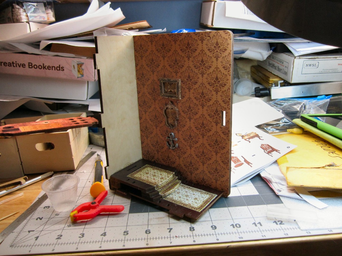
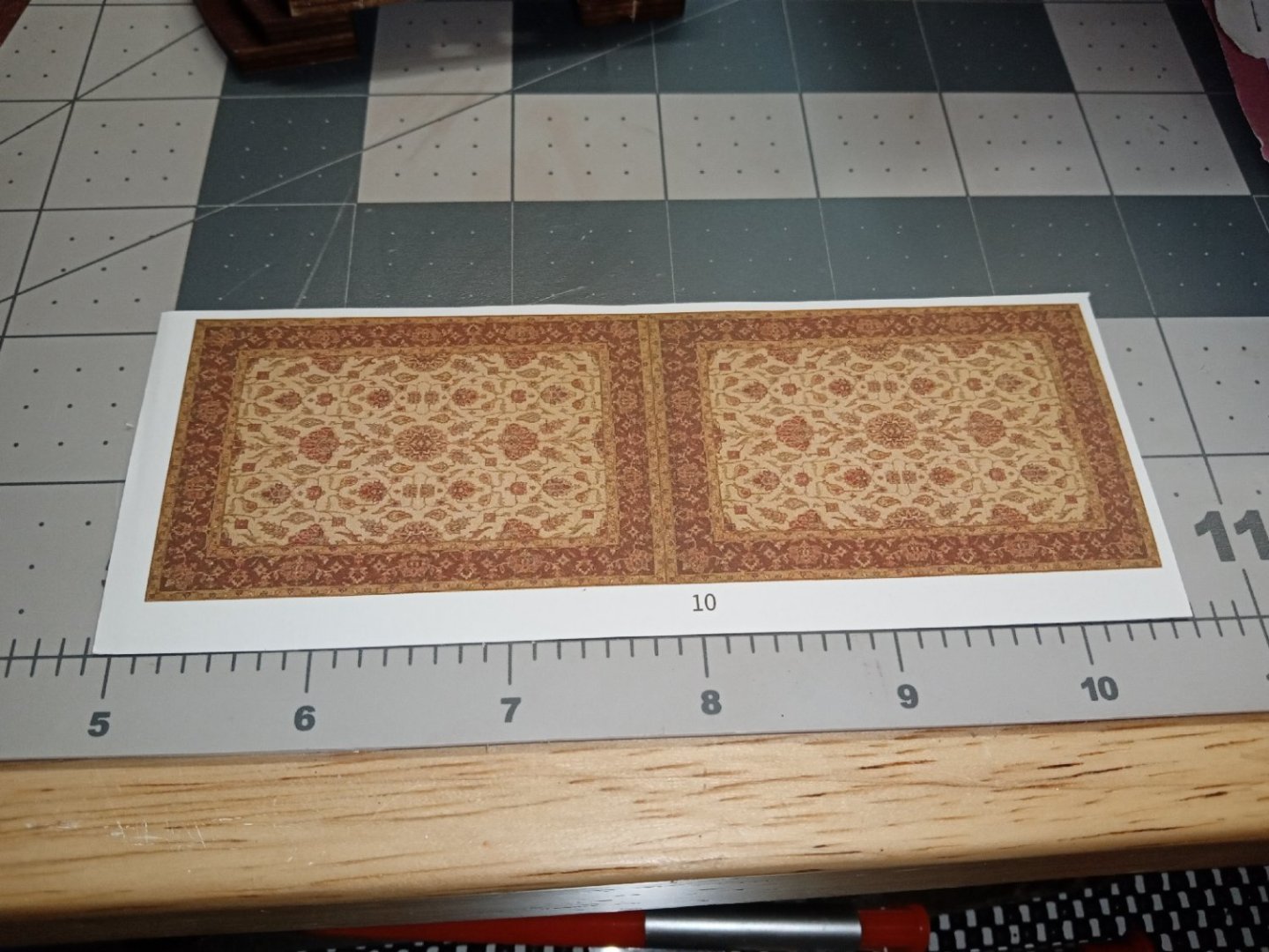
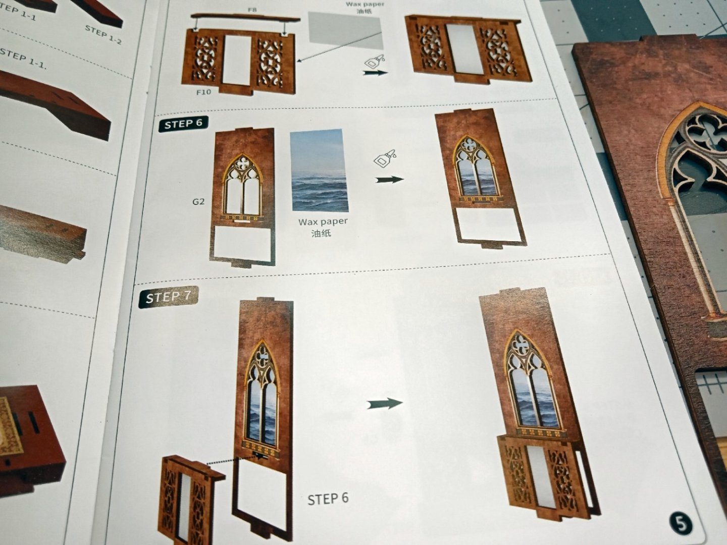
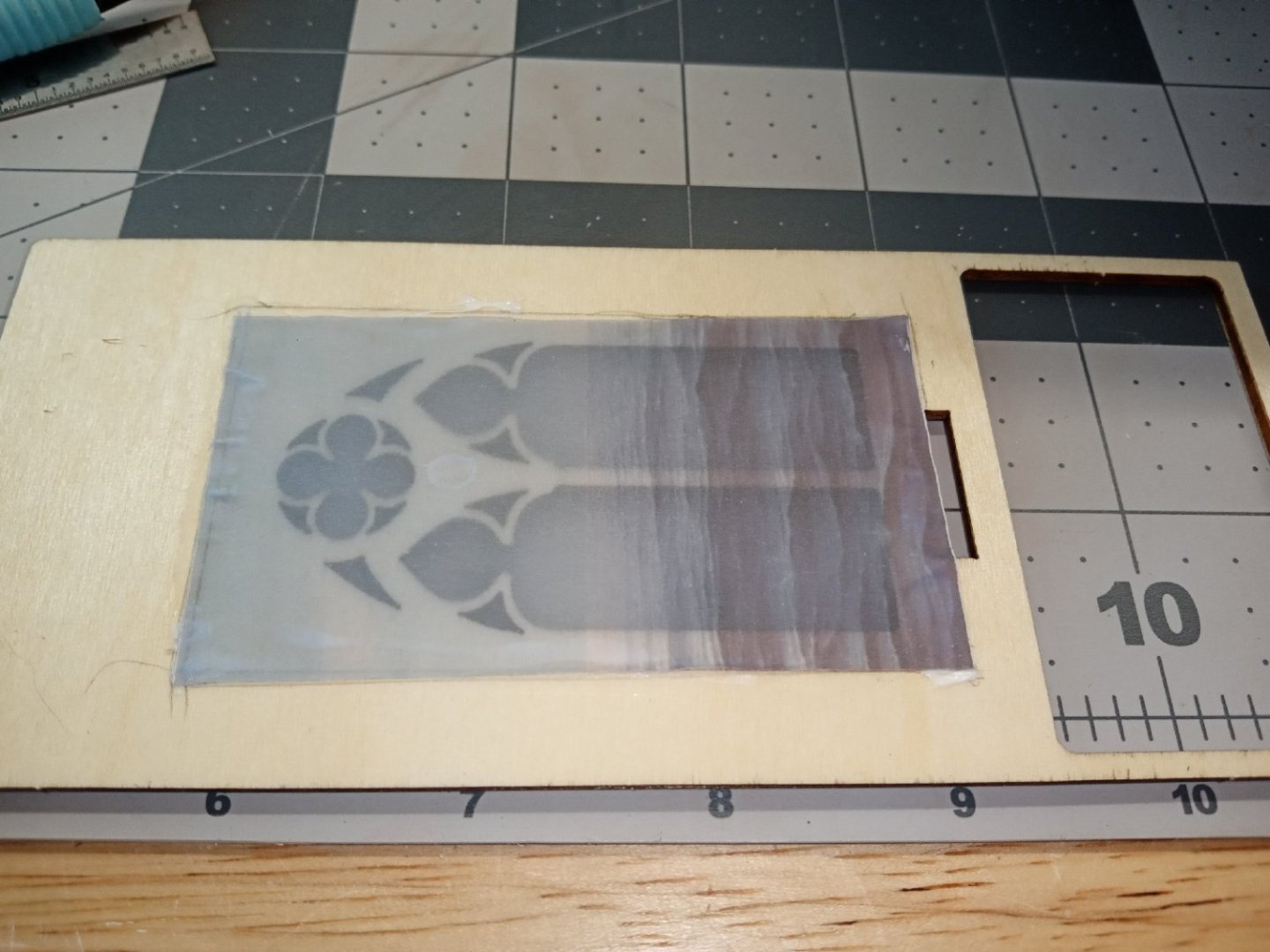
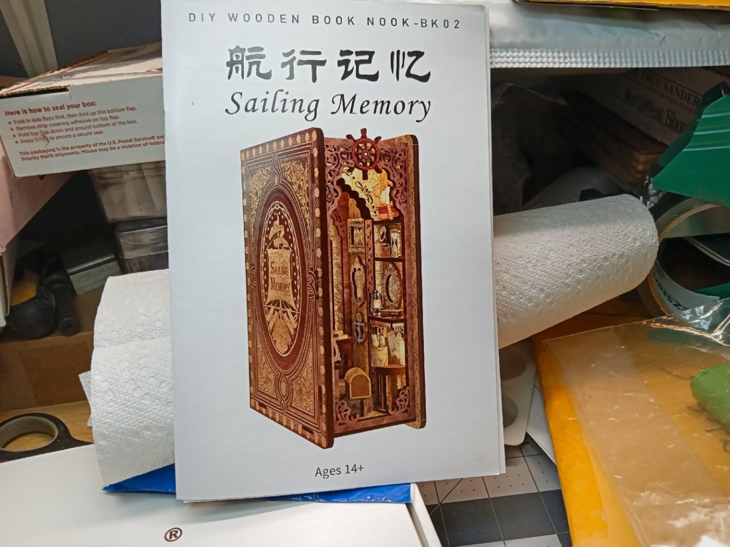
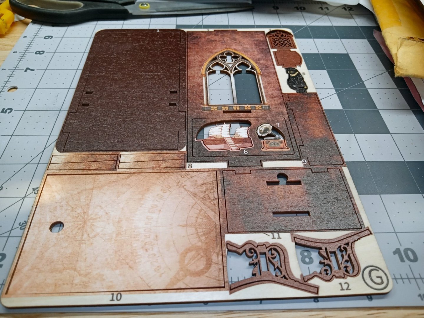
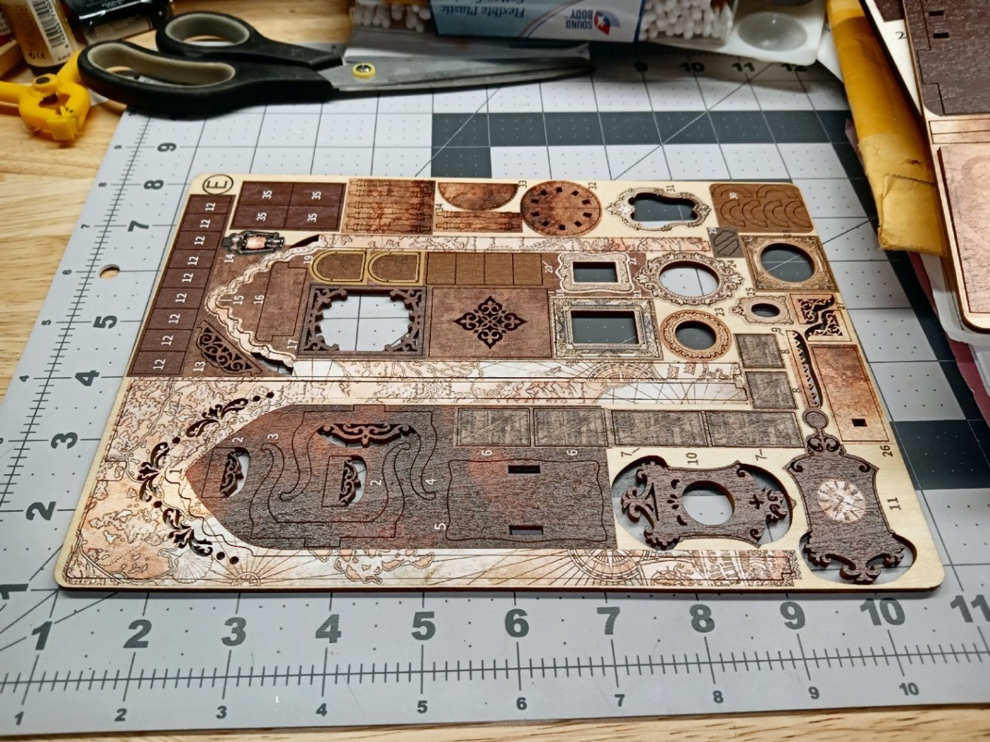
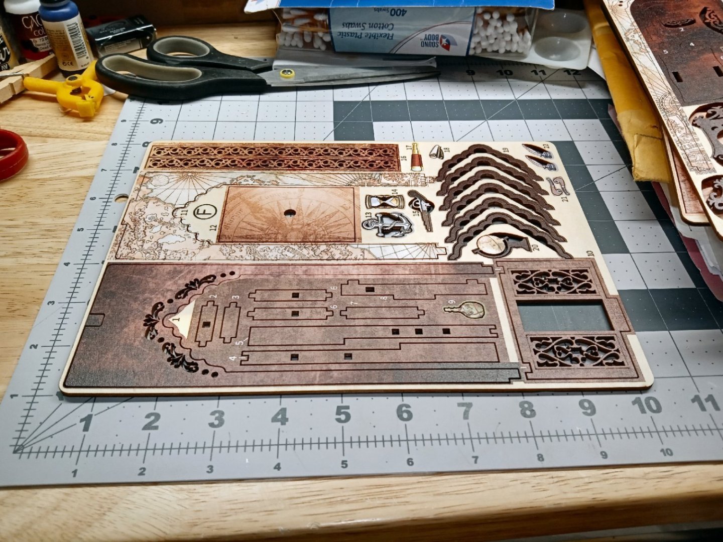
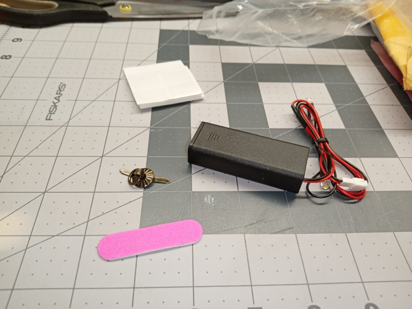
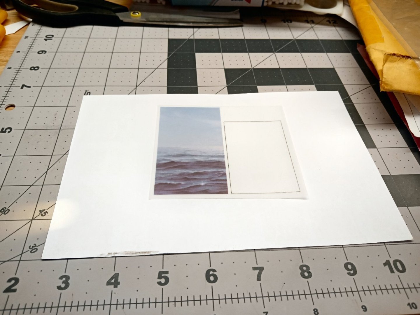
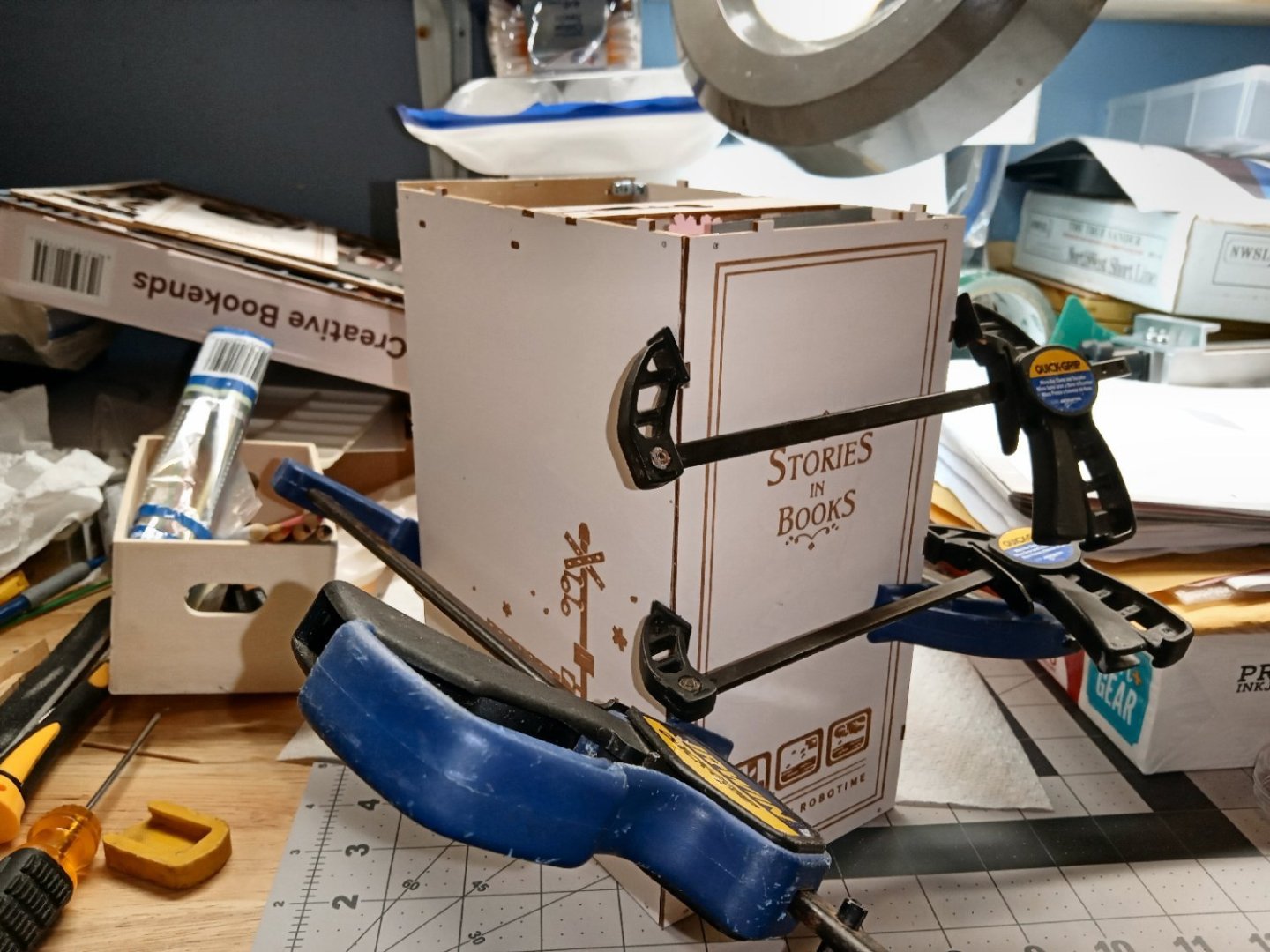
Part 001 The next Book Nook type diorama I’m building is “Sailing Memory”. I figured a ship themed diorama would more fit with this forum. It is the least complex kit so far, but it does throw some “Curve Balls”, so follow along. This first part will show the contents of the kit. Construction will start in Part 002. The first thing to note, is that except for the book cover parts, none of the plywood sheets are printed on the back, like the other two kits were. For the most part, this is not a problem, but it does present problems for the chair and table, so far. Both are printed in a mahogany wood grained color, which was hard to match. As I like to paint the lasered edges, this was a problem, especially the chair which has raw wood on the inside of the arms. Also, this model has many more colors than the previous kits, and trying to come close to the right colors on the exposed ply edges, has been a challenge! One thing of importance on this kit, about a year and a half ago I bought what I thought was this kit, for far less than the price of the other vendors. That was a huge mistake, and I should have known better! What I got was this kit, but with all the “details” printed on the insides of the covers, no 3D detailing at all, and the printing was fuzzy to boot! If you are getting this kit, find a vendor that shows the 3D detail up close, not just a shot of a completed kit! I have already progressed in the construction, and while I took pictures as I went, there may be some gaps in this thread. I missed taking some pictures along the way. Normally I write the sections as I go, but life threw me some challenges the last few weeks, and I’m just now getting to the writeups. Here are the contents of the kit. This is the picture from the cover of the instructions of the completed kit. The box is just plain white cardboard, so no picture of that. The next two pictures are the outsides of the book covers/shell. I’ll show the printed insides when construction gets to that point. (Mostly because I forgot to take those photos when I was shooting these, and had already started construction, when I noticed their lack.) The next few pictures are of the remaining plywood sheets. Matching colors for all those edges will be fun, not! You can see the woodgrain detail printed on the sheets. This sheet has the back wall of the diorama, with the fancy window. This sheet has the cabinet front that the white translucent sheet glues to, in the lower right corner. The accessory bag has the LED assembly, and a sheet of glossy clear squares, that I think are to put over the small books in the model, after you build them. I probably will not use these, as I think the flat finish on the printed covers looks better. Here are the contents of the bag. The LED assembly, a ceiling fixture, A small sanding stick, and the folded sheet with the glossy squares. Another reason I don’t think I’ll use the squares, is that when I opened it to see what it was a couple of the squares stuck to my fingers, and were ruined. This is the printed paper sheet with several details. There are pictures for some picture frames, maps to be glued on, the book covers that will be glued to wooden book blanks, and a carpet for the floor (much more on the carpet later). Lastly this is a translucent sheet with two pieces to be glued on. The colored seascape is glued behind the ornate window at the back of the display, and the white blank goes behind the front of the cabinet that sits against the back wall. This is similar to the Japanese style with paper “window” covering, like the old-style houses. When the model is finished both of these will be backlit, for a nice effect. This may be a little incorrect for the cabinet, but it will still look good. I have jury duty next week so there will a gap in the writing of the thread.


-
Does the protection take into account the containers falling off the ship when it impacts the barriers?
-
Laptop recommendations?
thibaultron replied to Mike Shea's topic in CAD and 3D Modelling/Drafting Plans with Software
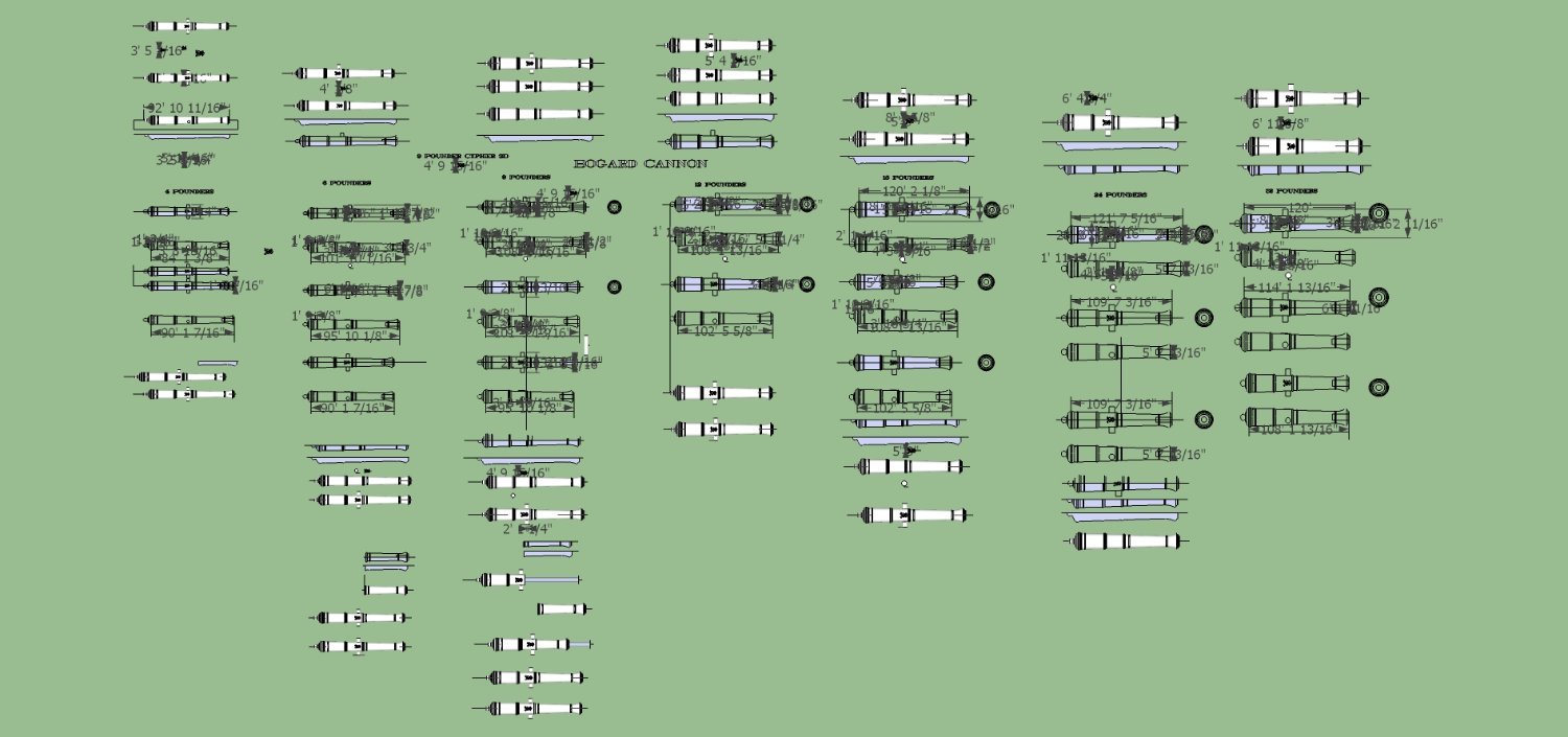
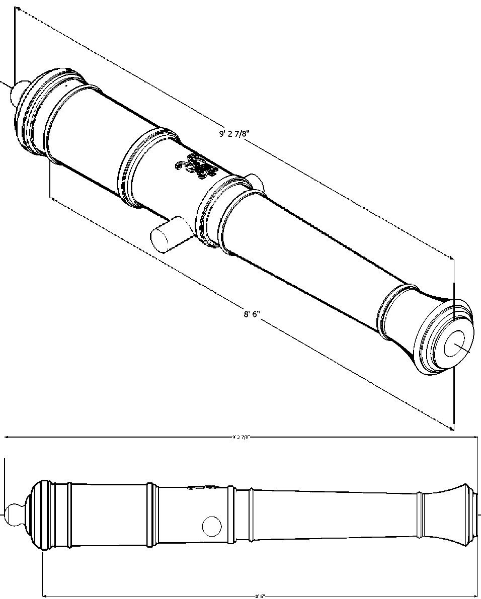
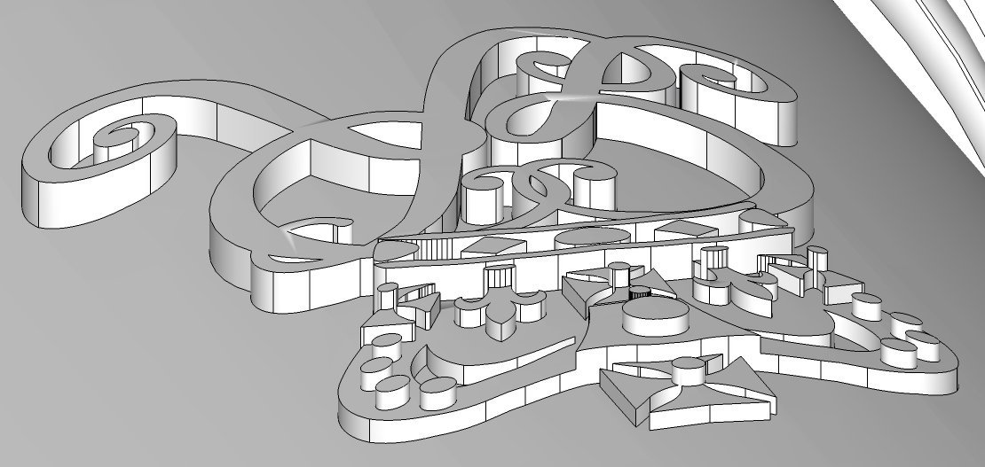
As far as CAD goes, you do not need a high core count CPU! All, I repeat all, CAD programs are single thread programs! I fell into that mistake when I built my new computer, last year. I have a 12 core CPU and none of my CAD programs were using more than 4 cores! When I investigated, all the 2D and 3D CAD program vendors state, if you look hard enough, that any CAD program has to be single threaded, as, basically, you start from one line,than follow it to the next line etc. CPU speed, on the other hand does matter, as well as how the CPU handles code. I went from a decade old 4 core setup, with a clock speed of about 4GHz, to the latest 12 core AMD 7900X with about 5GHz. In single thread the old one got a score of 450, the 7900X 2400. So it is about 4 times faster. The "Scores" are relative to that particular Benckmark program, the ratios do, however, indicate the relative performance. In multi core tests the old one got about 2K and the 7900X 27K. I have detuned my 7900X to run at a slightly lower total wattage, to lower CPU temperatures, and it runs about 3 to 5% slower, but now stays in the low to high 70C range of temperature, under full load, rather than the 90 to 95C limits the manufacture allows it to run at, for maximum performance. Intel runs in similar temperature ranges. I could have saved some money and gotten the 7600 or 7700 CPUs, as the CPU intensive work I do is mostly CAD and, not video or picture editing. I don't know if Blender falls under the single thread limit. Both the old and new computers use a maximum use 4 cores with my 3D CAD and Sketchup programs. Yes the program is single thread, but I guess some of the tasks can run in parallel. For Graphics and most other processor intensive programs the more cores the better. Also more cores allow you to have multiple CAD programs running without one bogging down the others. For Instance to copy an item from one Sketchup file to another, you need to have two or more Sketchup programs running, with each having one of the items. You copy an item in the first program, then switch to the other program, and paste the that item into the second. You can also have two SU programs running, and have one doing something complex, that will take a long time, and work on a second project, in another SU program while you wait for the other to finish, without slowing everything to a crawl. The CPU intensive operations in my SU work are generally grouping and ungrouping the lines in an object, and importing some non SketchUp file formats. I have an older free version (2017) of SketchUp, so I don't have the other programs that come with the full version. With my old computer, some of the operations might take overnight, on the new computer, a couple hours. Most now finish in a few minutes. With the larger number of cores you can also open other tasks, say a different CAD or Graphics program, and work on those while the SU program calculates. Graphics programs can use multiple cores, so the speed gains are greater. I don't do gaming or video editing, so don't need as high an end a GPU either. I bought the AMD 7600 GPU, and it barely sweats with my workload. If you get a laptop with a replaceable Nvme SSD, you will also see greater speed gains than one with a regular hard drive style SSD drive. That also allows you to replace a failing drive, or expand your capacity. I would highly advise against a MAC! The SSD sticks in them are soldered in, and of a proprietary form factor. Also the most common MAC laptop failure is for the chip that converts the power supply voltage to the different ones needed internally to die. When it does a vast majority of the time, it sends 13 volts to the SSD, frying it, causing the irreversible loss of all your data! No I'm not making it up, I did a lot of research. Apple is increasingly making it impossible for outside vendors to repair them. The latest trick was to start using a "Smart" switch to detect if the laptop is open. If it fails you can buy a new switch to replace it, but not the program needed to program the smart part of the switch! Only an Apple owned repair facility has access to the program. Without that program the computer will not recognize the replacement part. Whichever computer you buy, buy an external drive and frequently back up your files! Even if you have multiple internal drives, and back up the data to another internal drive, a major computer failure, say the power supply, can destroy all the internal drives! Also the minimum RAM I would recommend in a Windows PC is 16GB, with 32 or 64 if you are doing anything other than browsing or word spreadsheet work. As before, if picture or video editing the more memory the better. I understand that professional video editors regularly run 128GB of RAM. As an example, here is a screen shot of the set of Bogard cannons I am CADing in Sketchup, with this program and the browser I'm writing this response on, I'm using 11GB of memory. Opening a slightly older version of the same file, it goes to 14.6GB. So 32GB would be the minimum I need. I have 64GB, but the additional 32GB of memory came with the bundle deal I got when the CPU, motherboard, and memory bundle I got when buying the components from MicroCenter. In the graphic above the cannons farther from the center line are the latest version of that particular size. I build them in stages (make the body, add cypher, add trunnions, etc.), saving each stage as I go.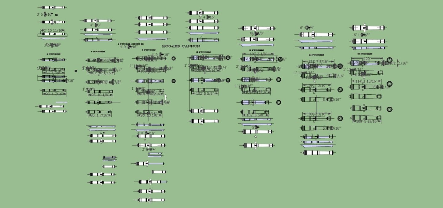
-
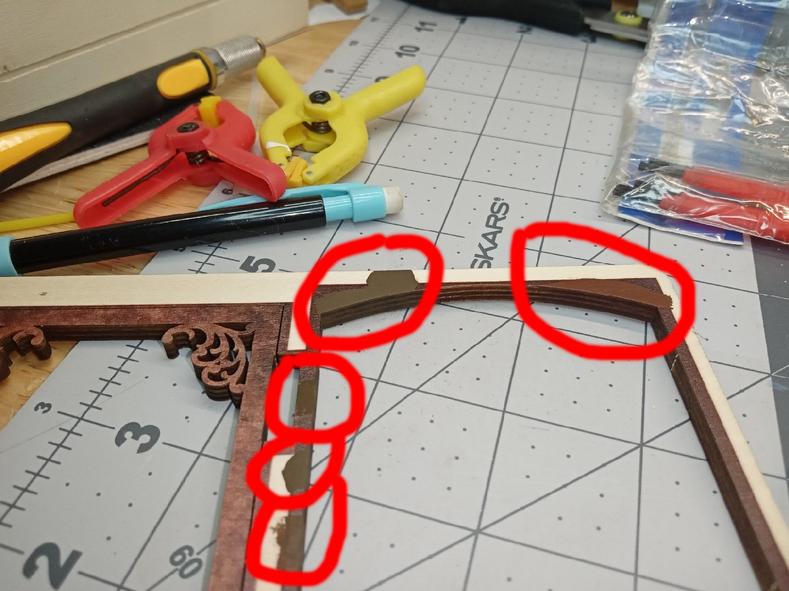
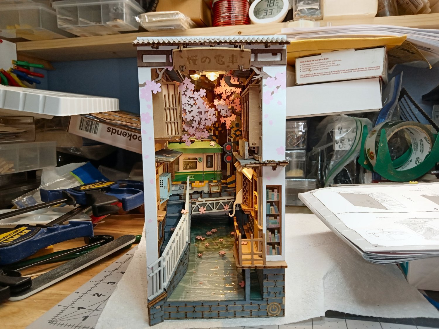
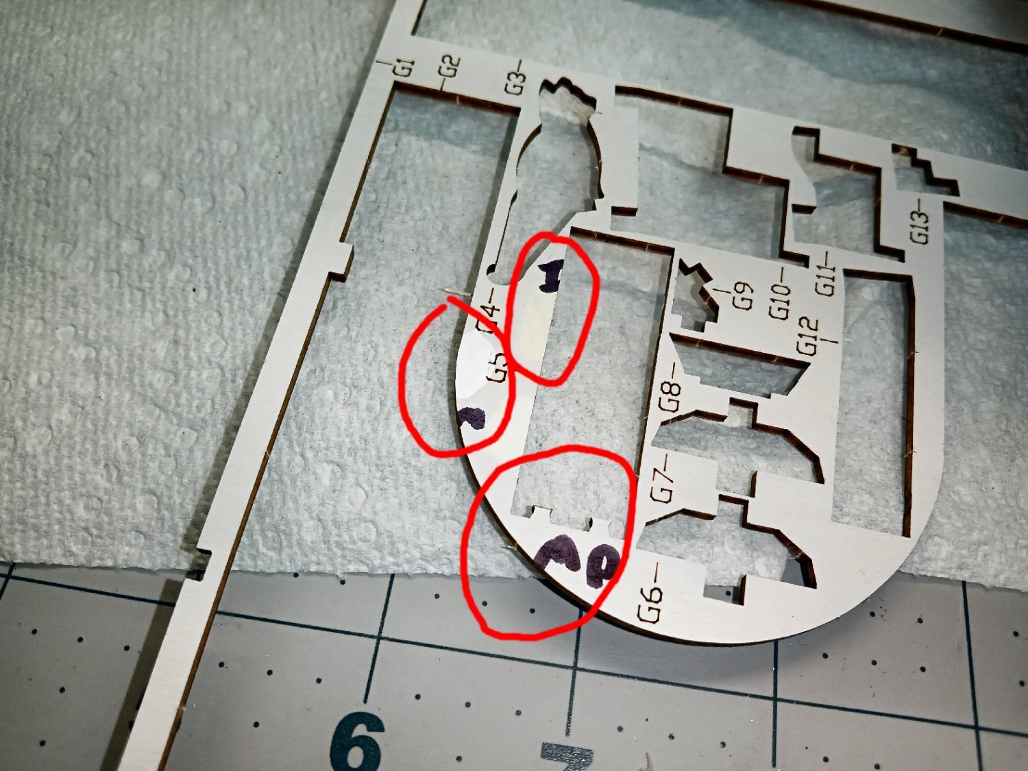
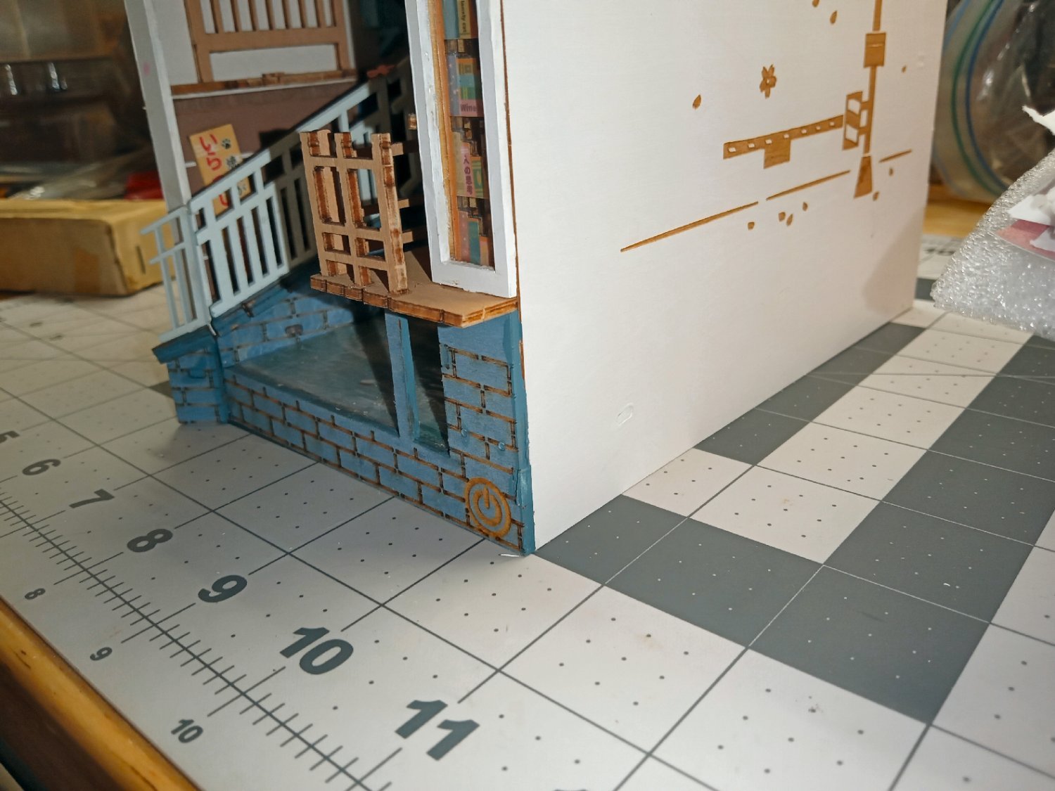
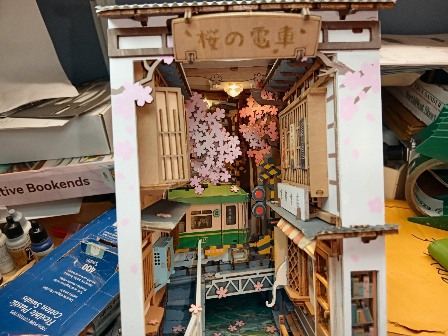
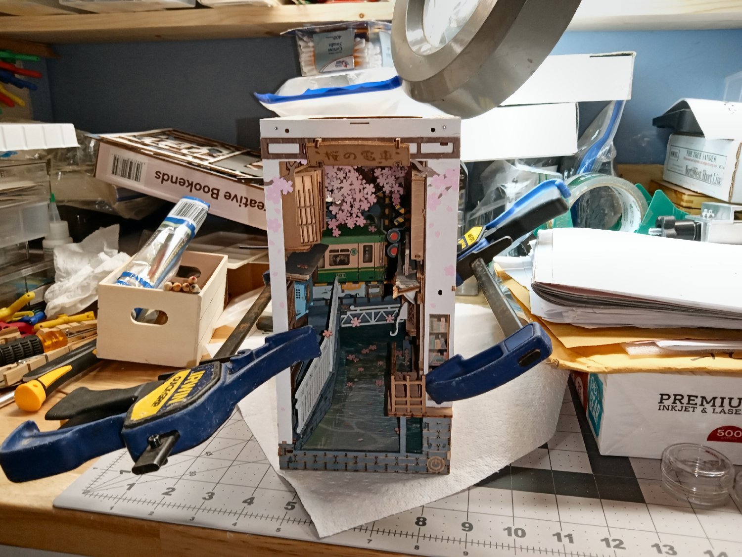
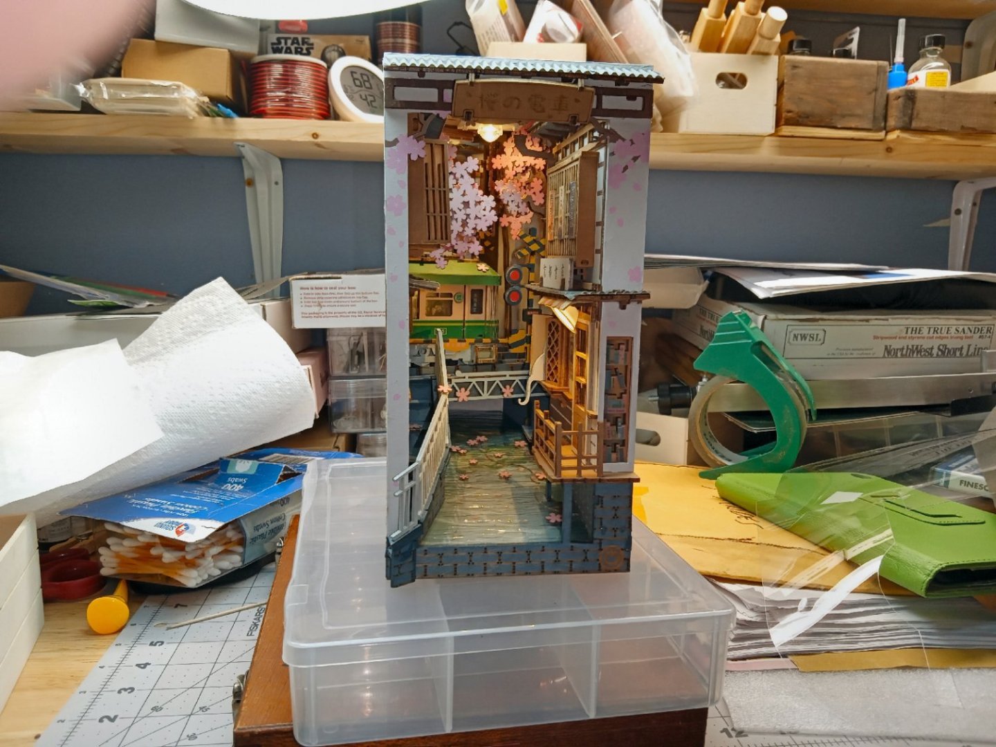
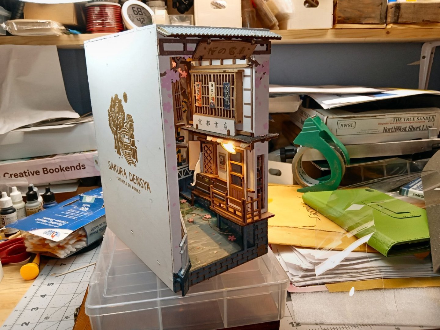
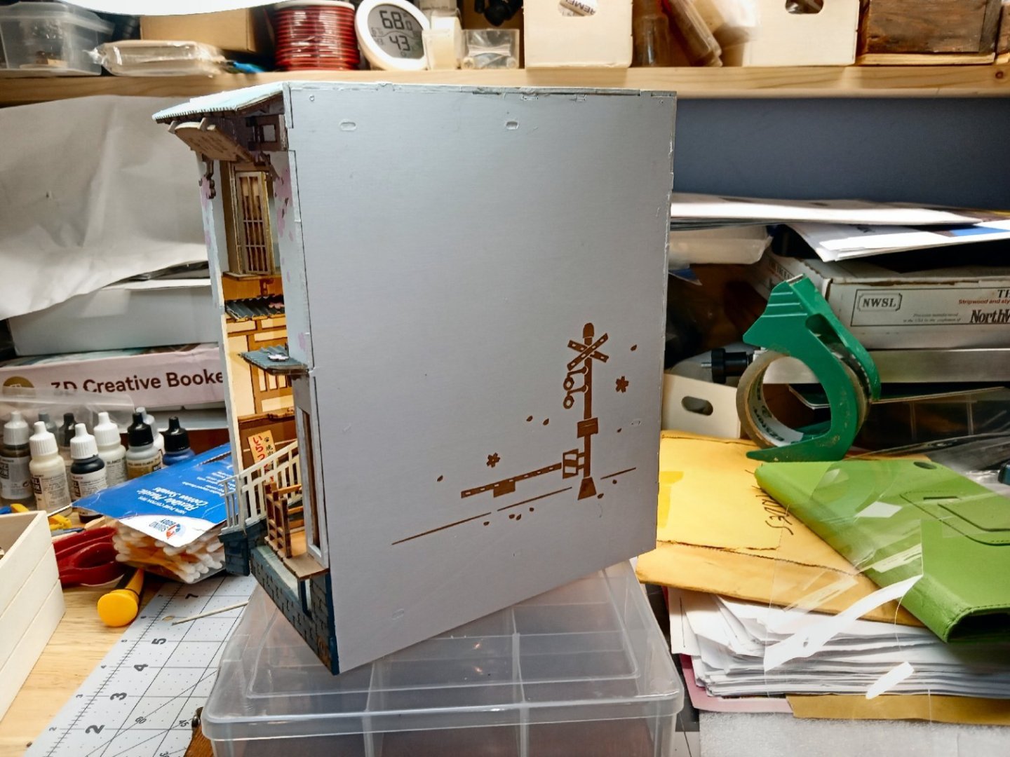
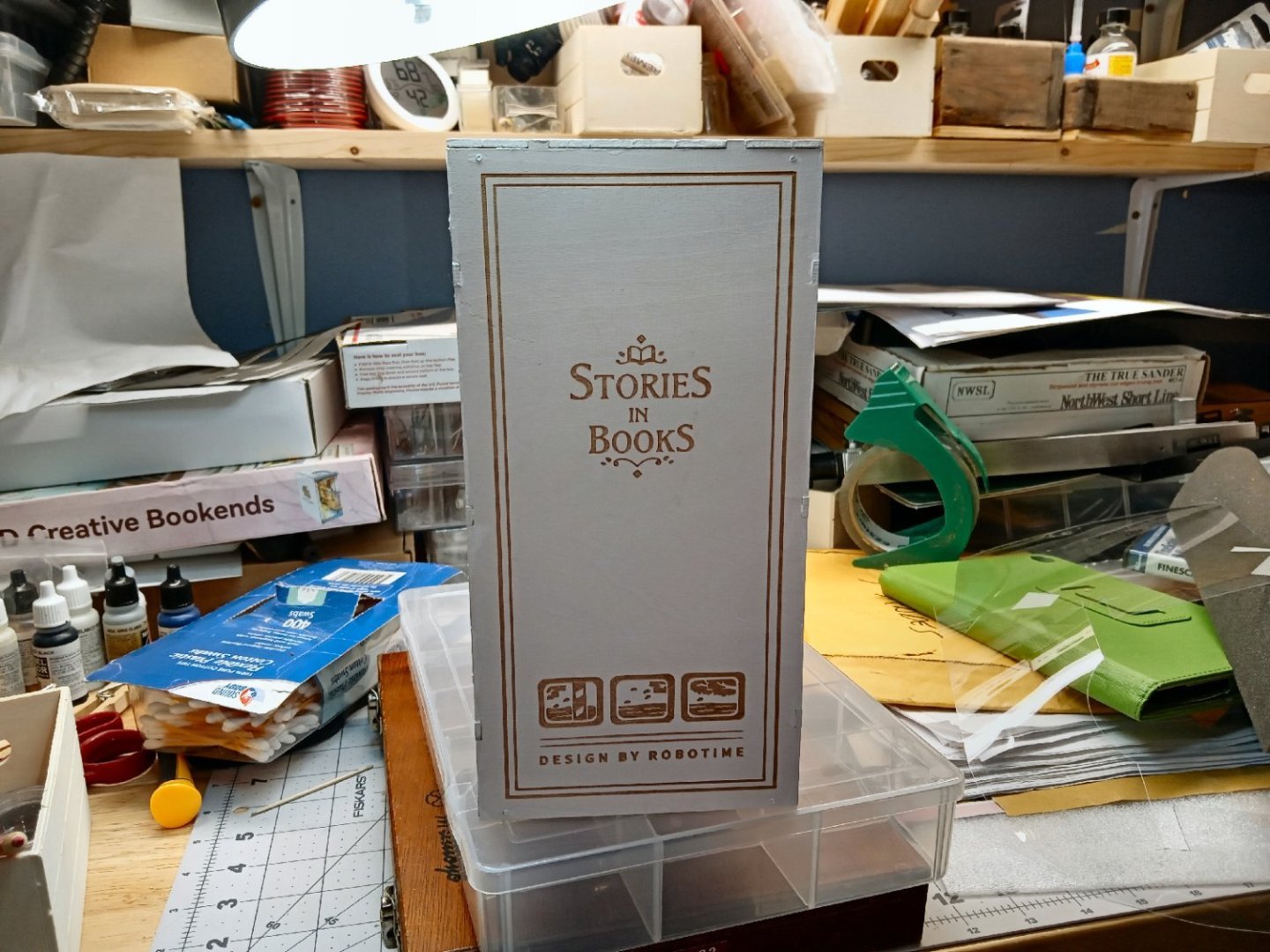
Part_021 This is a picture of the diorama with the LEDs on and an overhead light shining through the top window. The final steps to finish the model are painting the raw edges of the case. This picture shows some of the edges that need to be painted. I need two colors for this. The first is my blend for the masonry areas at the front. I decided to paint the outside edges the masonry color in the area the masonry was present. The other areas that needed painting were all the spots the “white” panels met. On the front plate I used pure white paint, but after looking at the finished model, I noticed that the panel color was an off-white color. I had three different “white” shades in my Vallejo collection, So I painted swatches of each on a sprue area the parts had come from. The results are shown in the picture below. The three areas I painted are marked by the red circles. At the top, labeled “I”, is “Ivory”. In the middle marked with what was supposed to be a “W”, is the standard white. At the bottom, marked ”OW”, is Vallejo's “Off White”. The Off White matched almost exactly. PS, yes, I failed in writing clearly in small areas with a sharpie. Sue me! LOL! The following few pictures show the finished paint job. I only saw the bad spot in the above picture, while writing this section. I plan to leave it as is. The area is not visible from the front at normal viewing angles, and I don’t want to mix a whole batch of paint for this one spot Another shot of the fully painted, and finished model from the front. The rest of these pictures are more shots of the finish diorama. I will shortly be starting another thread on a ship themed Book Nook diorama, called “Sailing Memory”. It shows a room with various nautical “stuff” on the table and walls, several books that need to be made, and a large backlit fancy window with an ocean scene behind it. The kit is simpler than the previous two, but has some interesting new building challenges. So, stay tuned, if it sounds interesting.


-
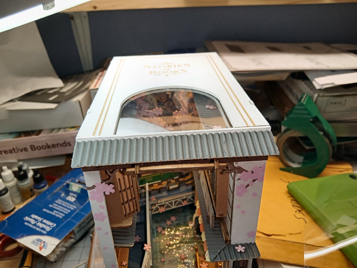
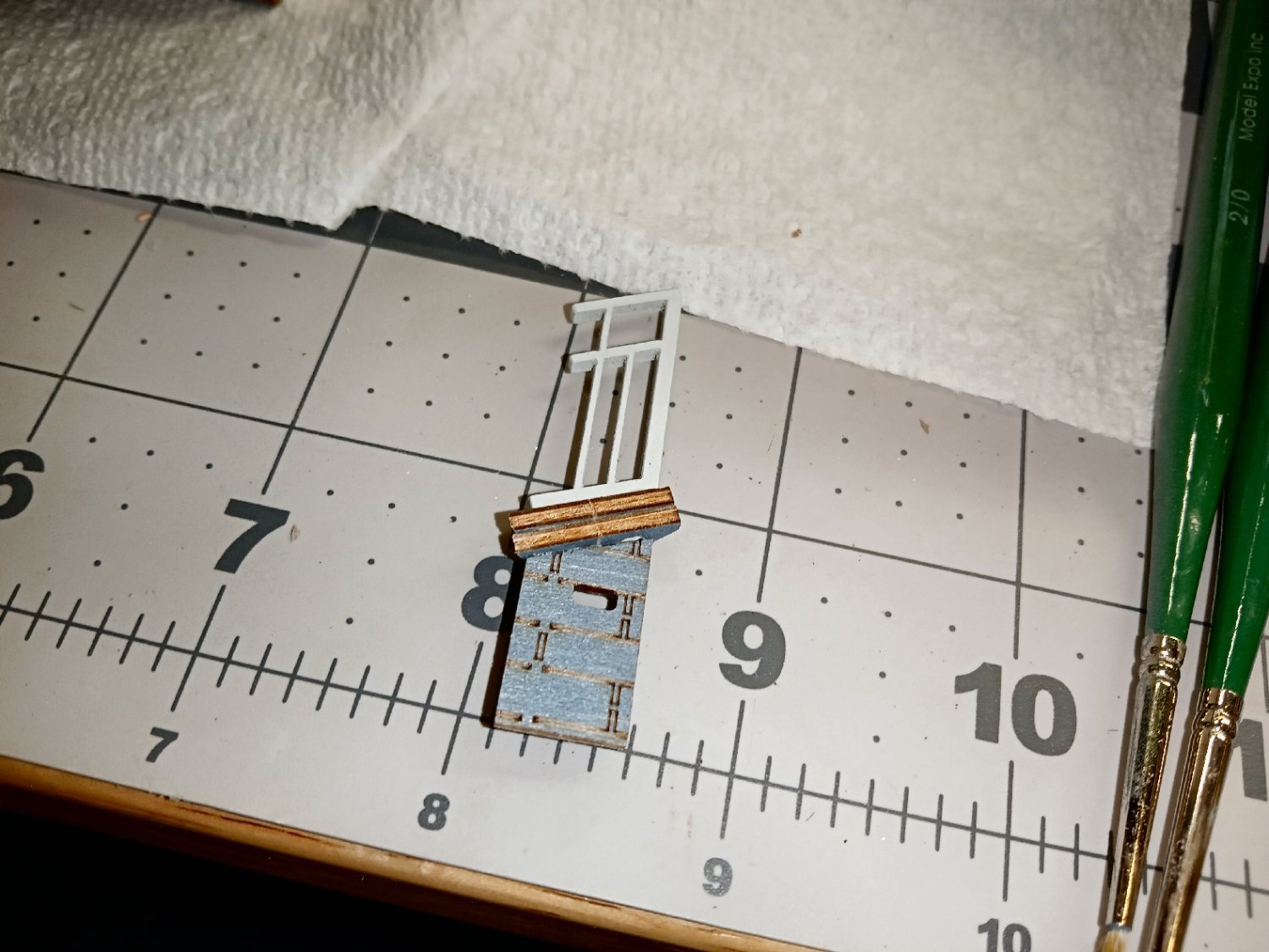
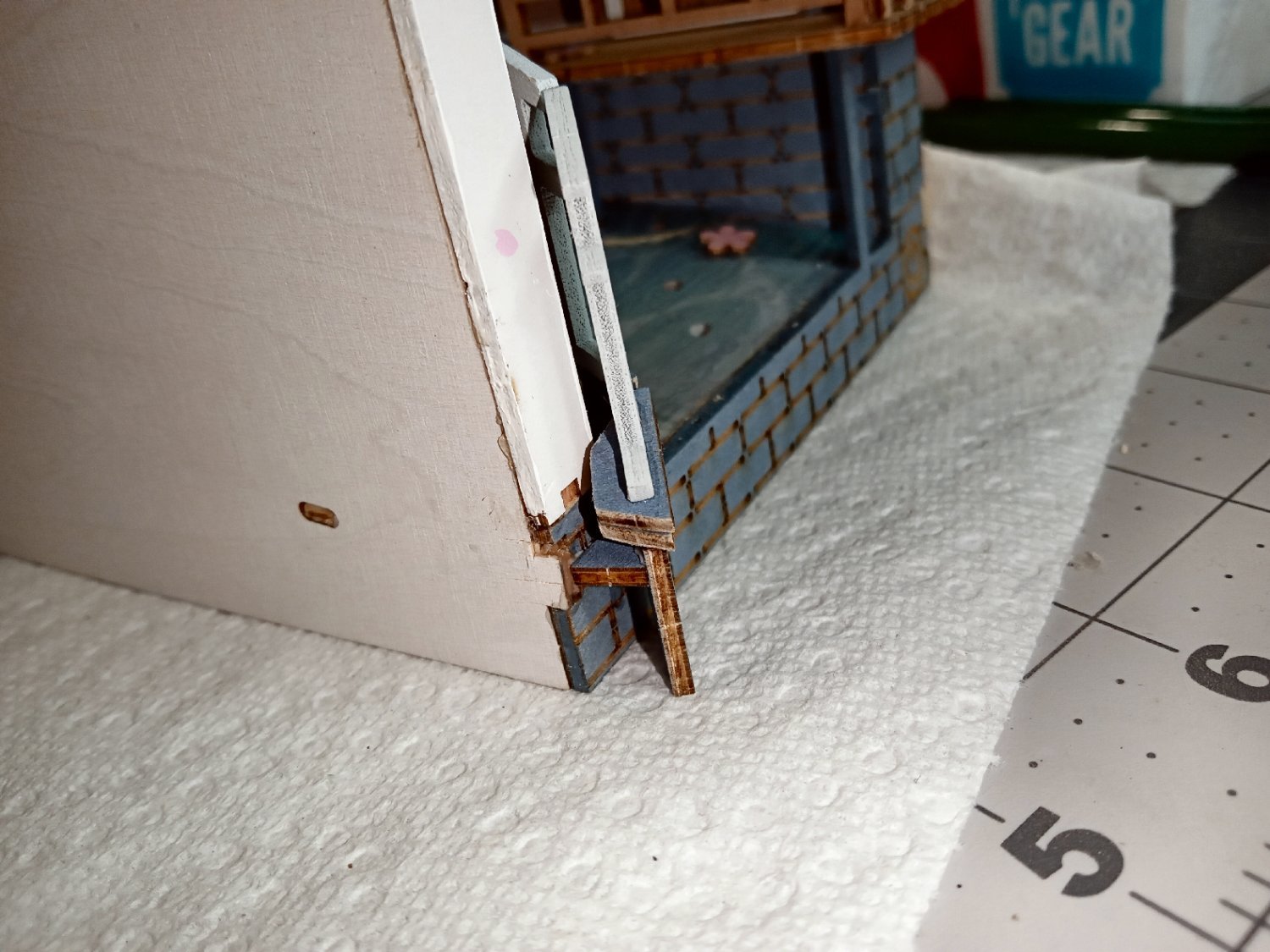
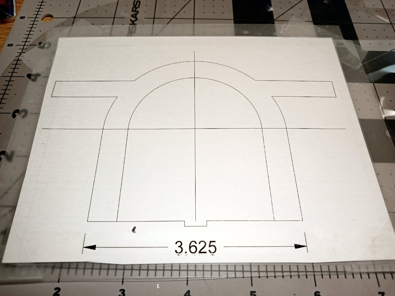
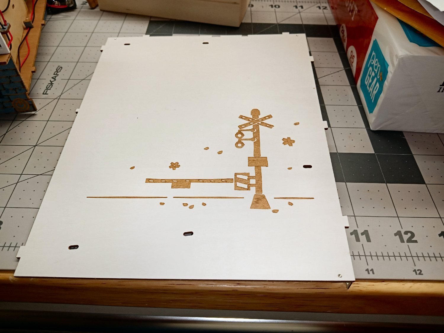
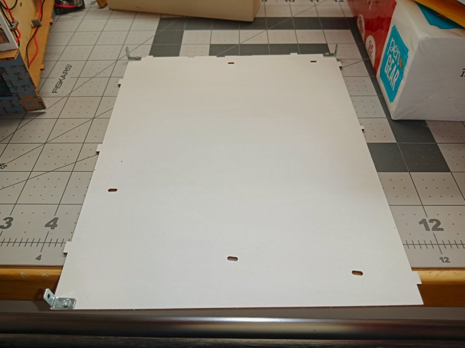
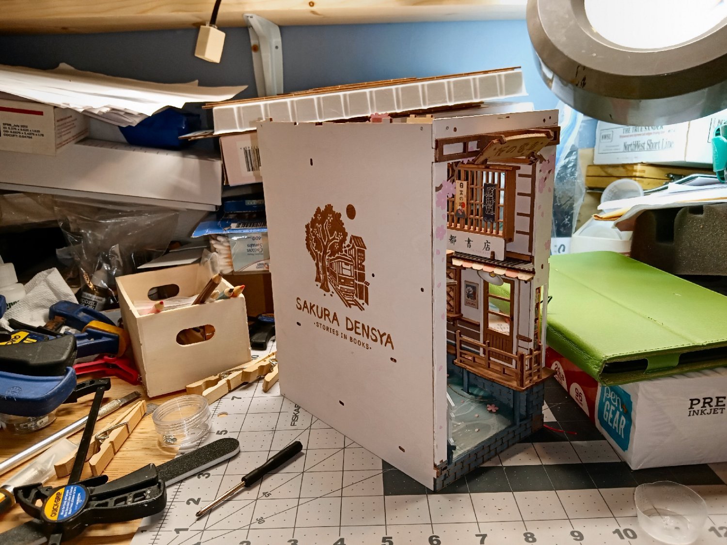
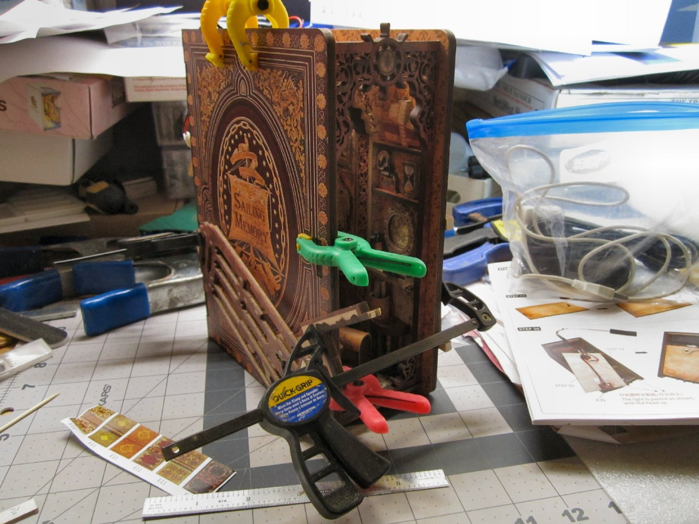
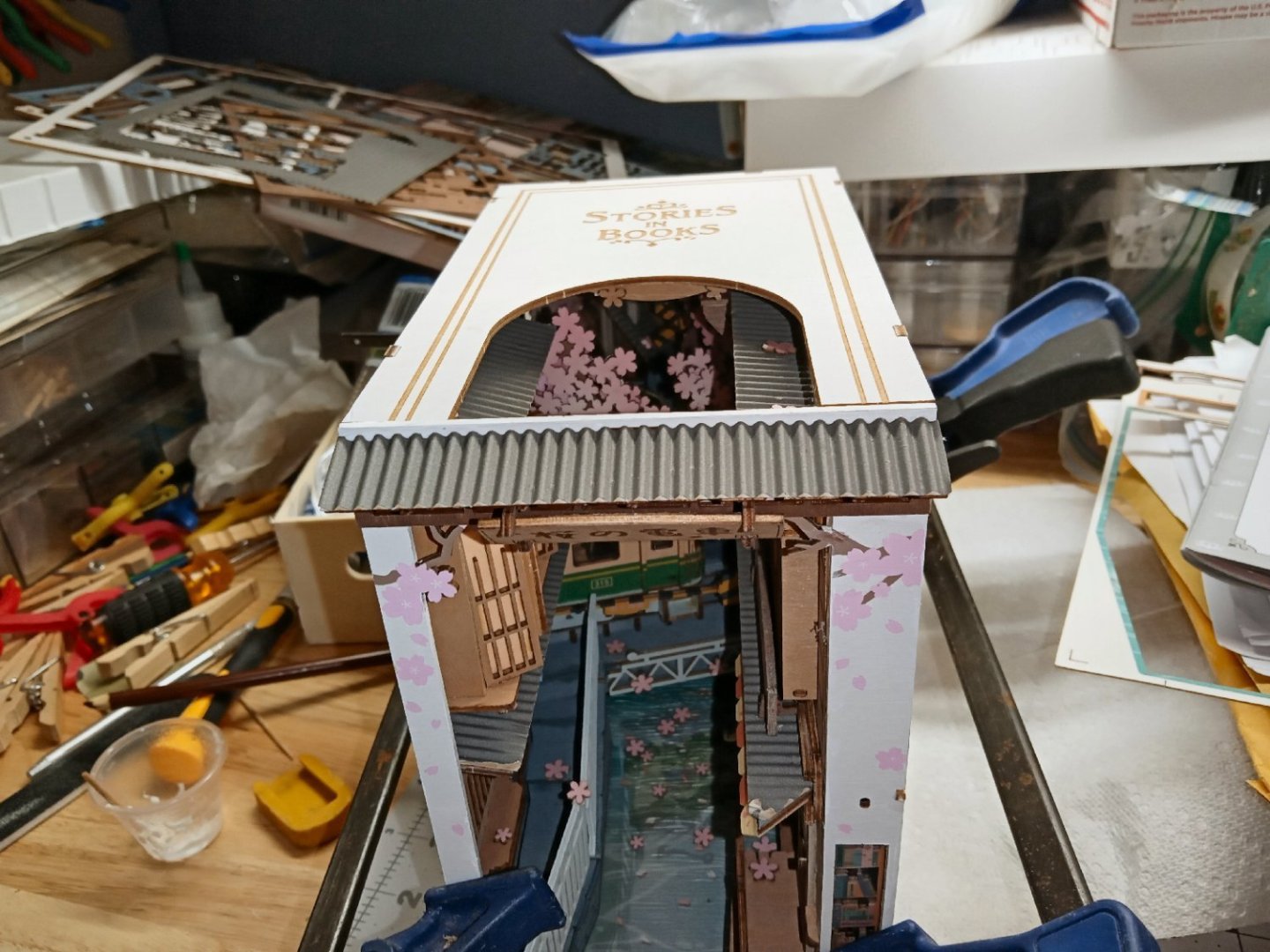
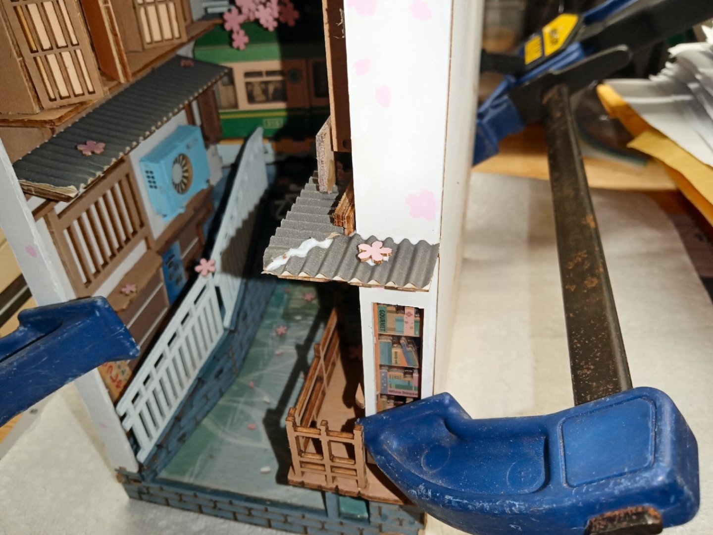
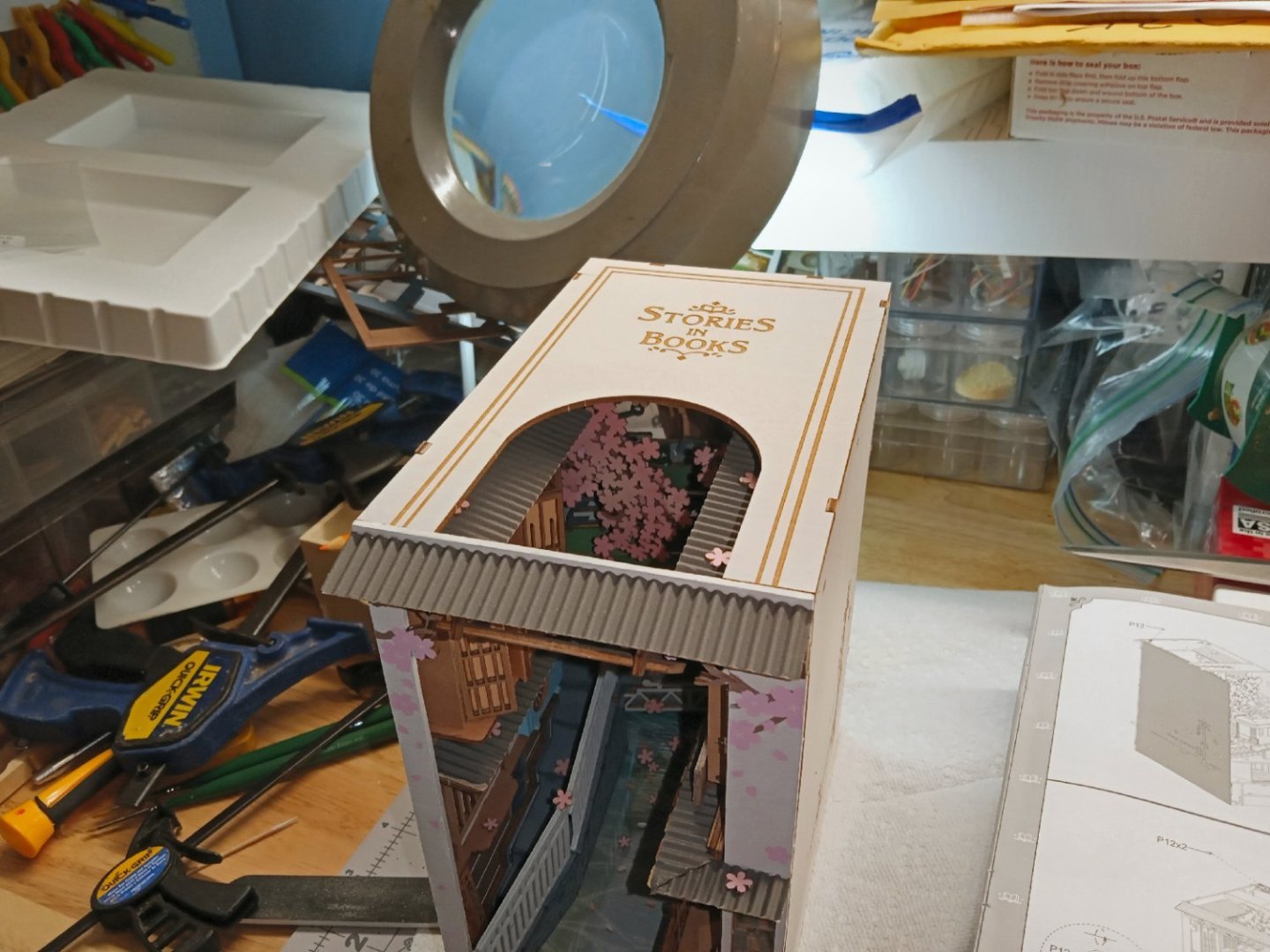
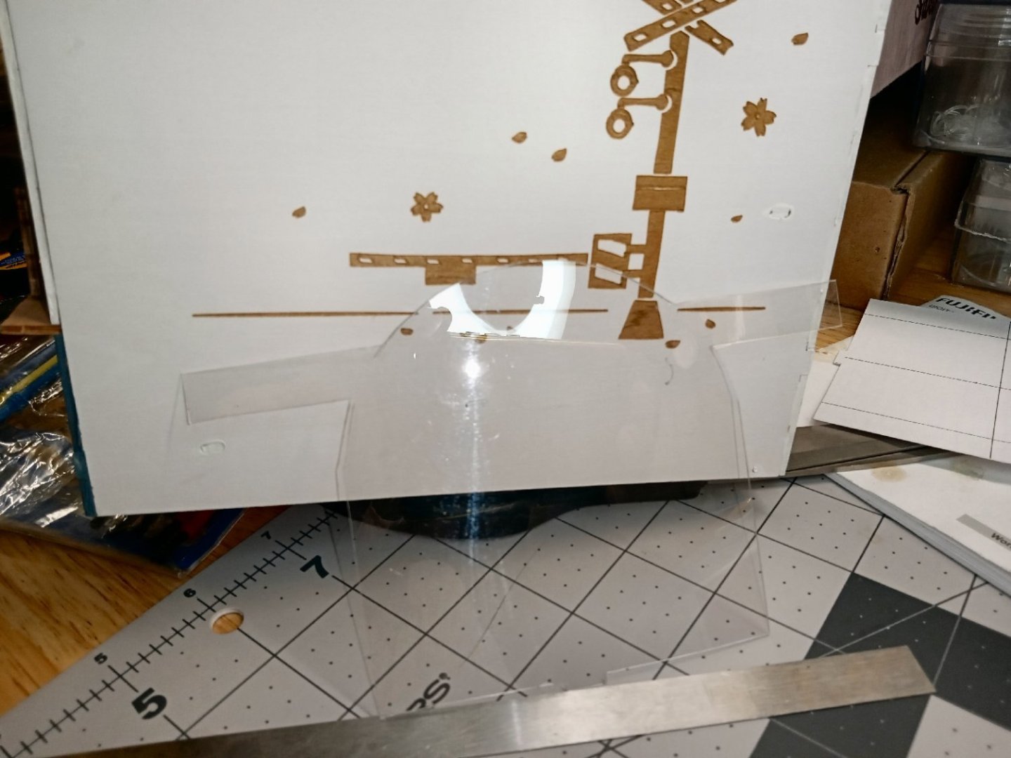
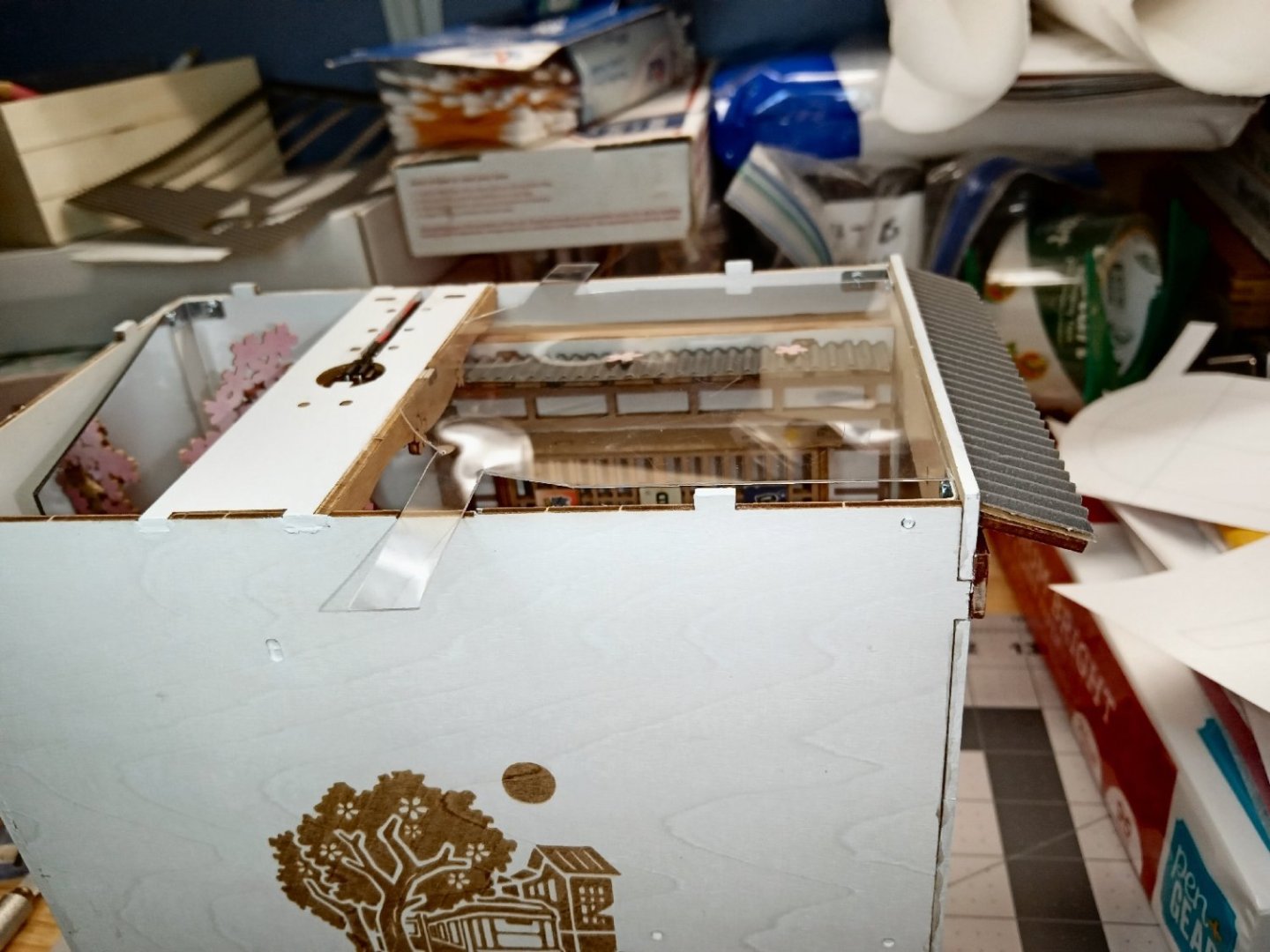
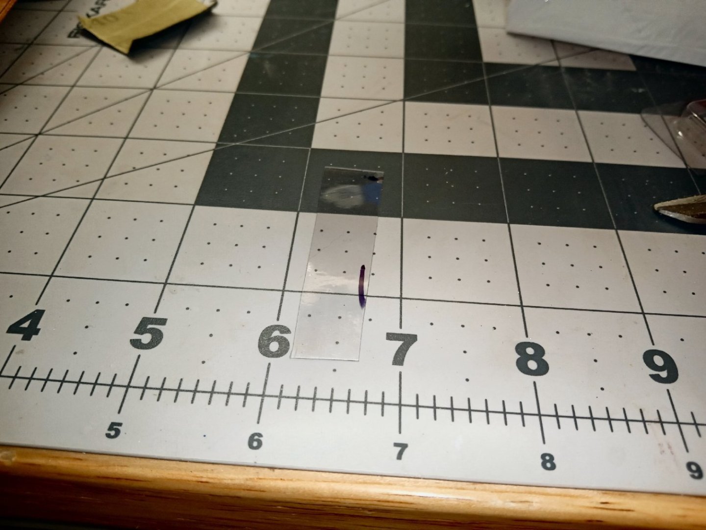
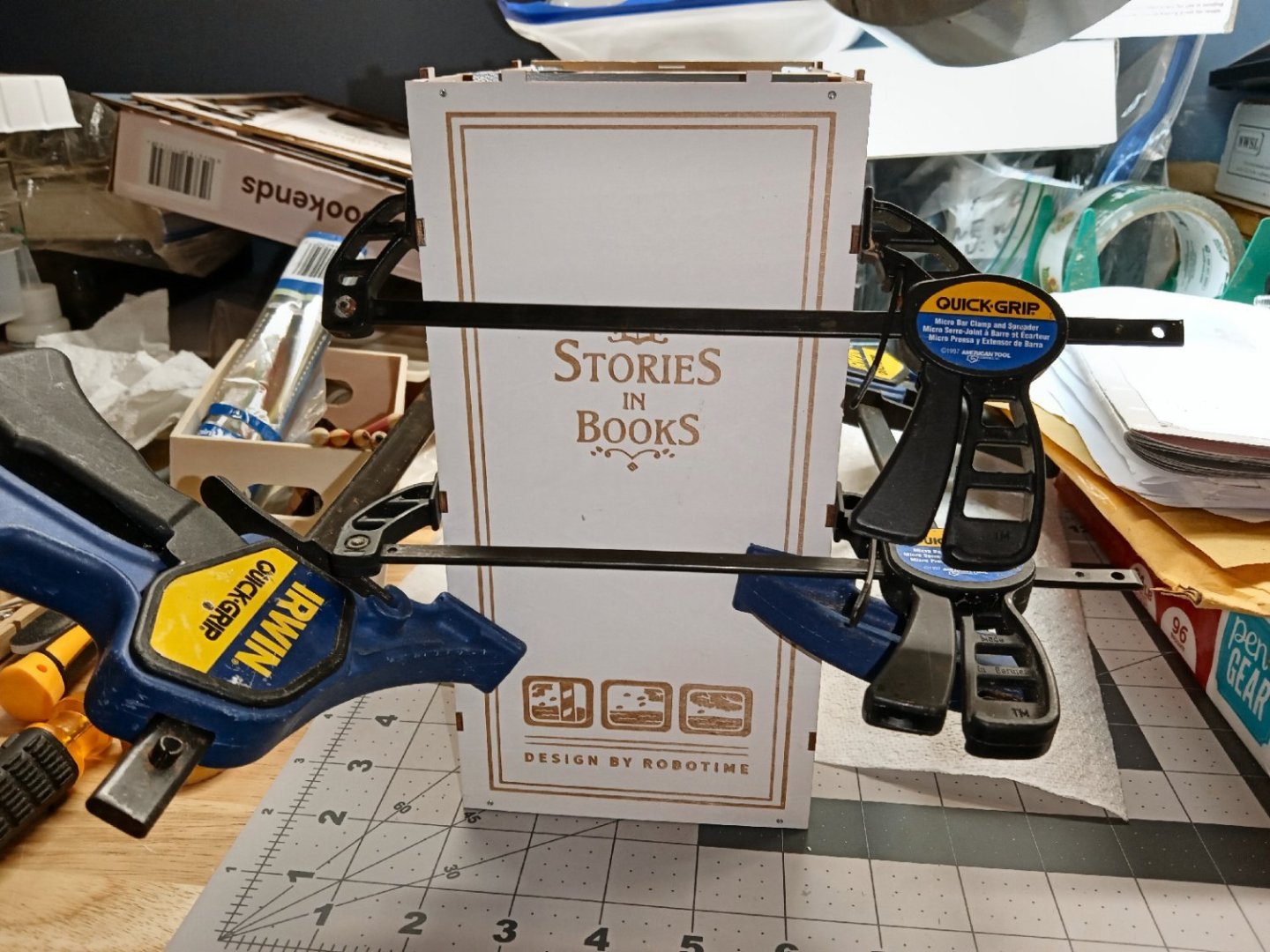
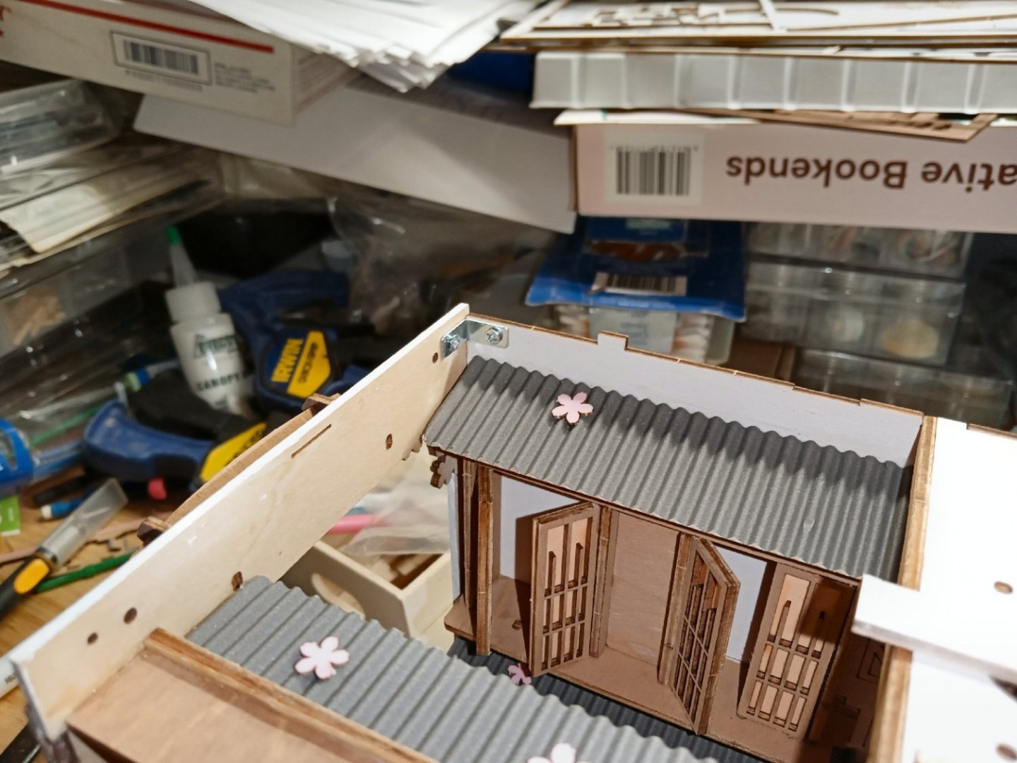
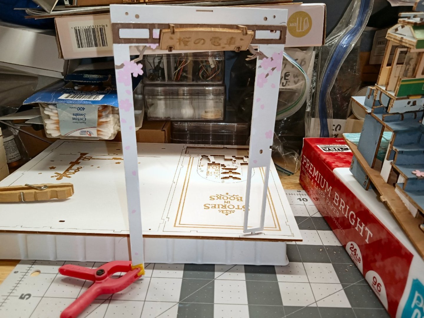
Part_020 The spine was glued and clamped on next. I dry fit the top to make sure that the case was square. There is still a distinct lack of window for the top, but there are a few details that need to be finished first. The first thing that needs to be worked on, is the joint between the two edges of the book store roof, where they meet at the front right corner. The two pieces were not level with each other. I applied a thick bead of glue, and held the pieces until the glue had set sufficiently. After the glue fully dried, I applied another bead to the underside. Because this area is on the outside of the case, I wanted to protect it from damage, if any impacts occurred. Though the bead does look like it is too large, when dried it shrinks considerably, and is transparent. This is also a small area. The stairway extension at the lowered left corner, are the next parts to install. A picture of the instructions for this is shown below. This shows the assembled wall and railing. This picture is of the corner bracket/lowest step, installed. I then glued the wall to the brace. After the glue dried, I added a bead of glue to the inside of the joints. I had still not found the acetate glazing piece for the top window. I was just going to leave the top dry fit, and leave it like that, until some point in the future, when I found the piece. I spotted a perfect piece of acetate, lying around my shop though! Back in the big bad COVID days, they made a lot of disposable face shields, unfortunately non were available in my area. However, afterwards, one of my pharmacies had a few spare ones they gave me, for use in my shop. Well, there was one open and sitting in a corner! After checking it was the right thickness for the holding slots in the case. So, I used it to fabricate a new window. Being a disposable shield, it was packaged flat, with a foam forehead cushion glued along the top, and an elastic band to hold it to your head. After the elastic and foam cushion were cut away, the sheet laid flat. The instructions showed an overhead view of the placement of the window, so I had a guide as to the correct shape. I traced the opening onto a sheet of paper. Then after measuring the various tab locations, etc. I drew a new pattern using my CAD program. Below is a picture of the finished pattern. The innermost lines are the opening outline. The two ears lock into slots in the side plates, and the tab at the bottom fits in a slot in the front piece that sits just below the edge of the front plate. This slot is hidden from the front by the roof overhang. The side ears were left overlong so I had handles to maneuver the window, without leaving fingerprints. I taped the pattern to the face shield, and cut it out. Though hard to see, naturally as it is clear, this is a picture of the finished part. After a little trimming in the area of the ears, it fit into place, one problem of measuring a metric model with an imperial ruler. Again, still hard to see. I put glue along several areas of the top of the side, back, and front plates, and using the ears to hold the window in place installed the top. I also put a few small drops of glue at the window to top joints. I don’t want it to shift in the future. After the glue dried overnight, I trimmed the exposed parts of the ears off, with a new blade. The construction on the diorama is finished, but there are still some painting details that need to be done. These and pictures of the finished model will be shown in the final part.


-
3D Naval Guns 1850s ~ 1870s
thibaultron replied to JerryTodd's topic in CAD and 3D Modelling/Drafting Plans with Software
Great models! -
Considering that you can see the background through the ship and sails, Photoshop!
-
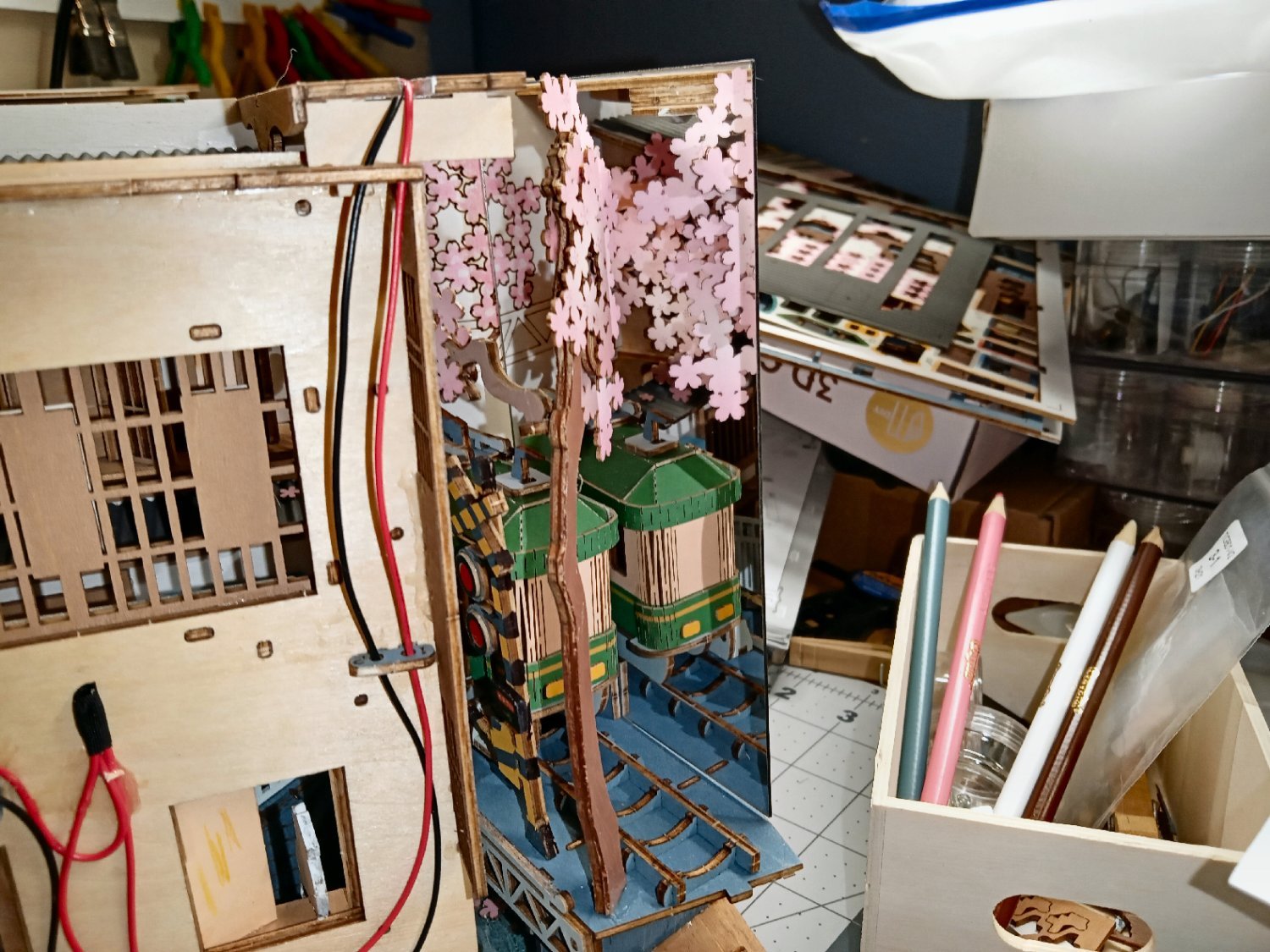
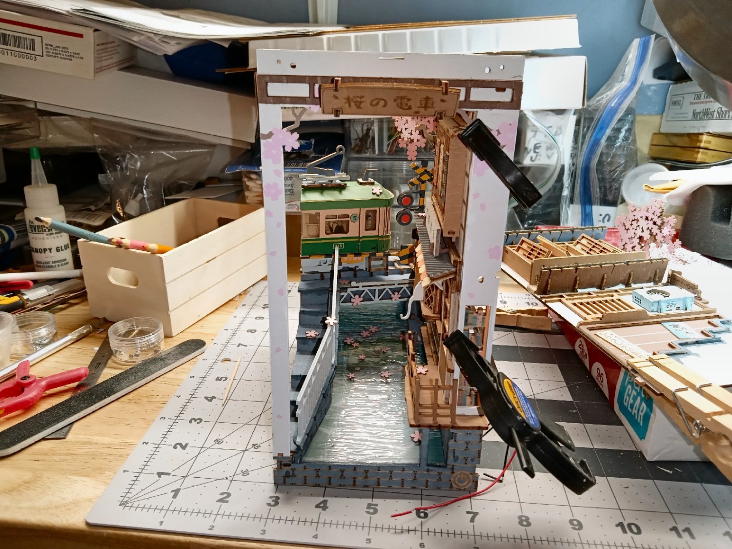
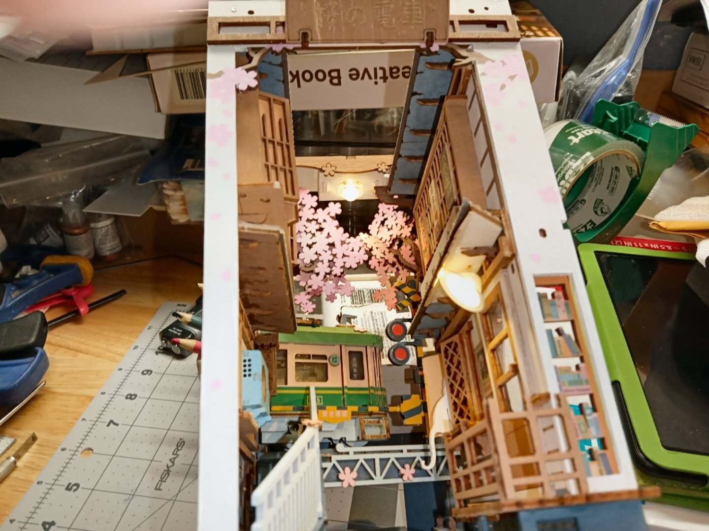
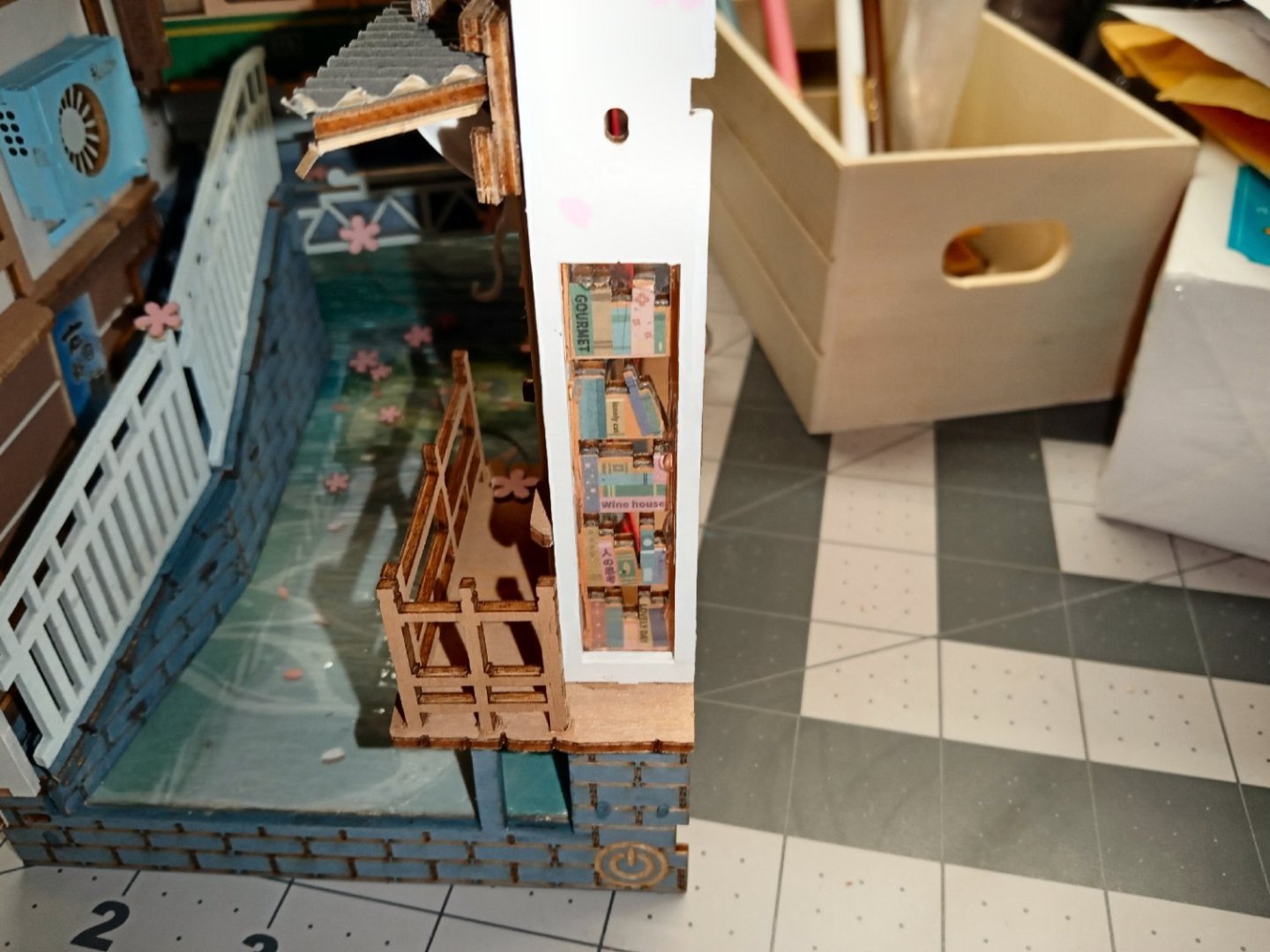
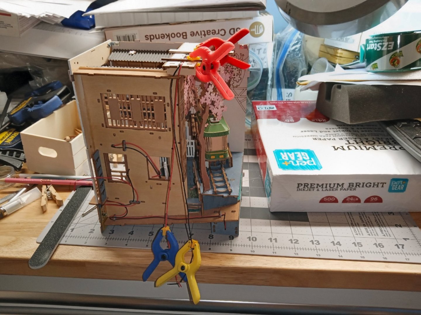
Part_019 This picture shows the upper LED wires in the slot, after the Canopy Glue dried. I installed batteries and tested the LEDs, before continuing. I still can’t find the acetate glazing sheet, so I fabricated a new window for the bookstore window, using plastic from a tool package. I wish I had thought of the plastic I used later for the window in the top cover, but I had already glued in and trapped this window. My fear is that the cheap plastic used in the tool cover will yellow over time. Oh well, time will tell. First, I glued the acetate to the back of the front cover, like in a real building. This looked good, but caused problems later, as will be detailed below. I used scrap wood to wedge it in place until the glue dried. While waiting on the window glue, I installed the rear diorama mirror. After removing the protective film from the “glass” side of the mirror, I slid it into place, and glued it. Here you can barely see the effect of the mirror. If you look behind the railroad cross arms, you can see the reflection, making it look like there is another one on the other side of the tram. It also looks like there are more buildings going down the street. There is also a reflection that looks like there is another tram behind the first one. This would be weird, but the second one is mostly hidden by the tree branch, and the second tram would be hidden if the diorama was above eye level, anyway. This is a picture of the mirror, from the side. The next day, I took this photo of the first installation of the window. These are pictures of the right-hand cover. I don’t know if I showed a picture of the corner brackets, they are shown for this wall in the second picture. I damaged the lower tab on the left cover when I installed it. I used three rounds of building up layers of Canopy Glue, to fill it in. When I went to install the right cover, I found that the bookstore window glassing interfered with the joint. I carefully pried it away from the wall, using a steel ruler. I first tried trimming it narrower, and reinstalling it. There was no room on the right side of the window opening left to glue that edge down. The inside surface of the right cover fits flush with the inner edge of the window opening! I retrimmed it to fit over the inner book wall, which does have a lip on the right, as per the instructions and glued it to that wall. Once again, scrap wood was used to wedge it in place. I cleaned the canopy glue off the glazing using isopropyl alcohol, before gluing it in the second time. As I did on the left cover, I glued the front edge of the right cover to the right side of the front cover first, and clamped it. Notice that the cover is angled, slightly, away from the rest of the assembly, to clear the other mounting tabs. Once that had dried, I dry fitted (not glued) the rear/book spine cover in place, and clamped the back edge of the right cover to it. I then made sure all the connecting tabs between the base and right cover were inserted, and ran a bead of glue along that joint.


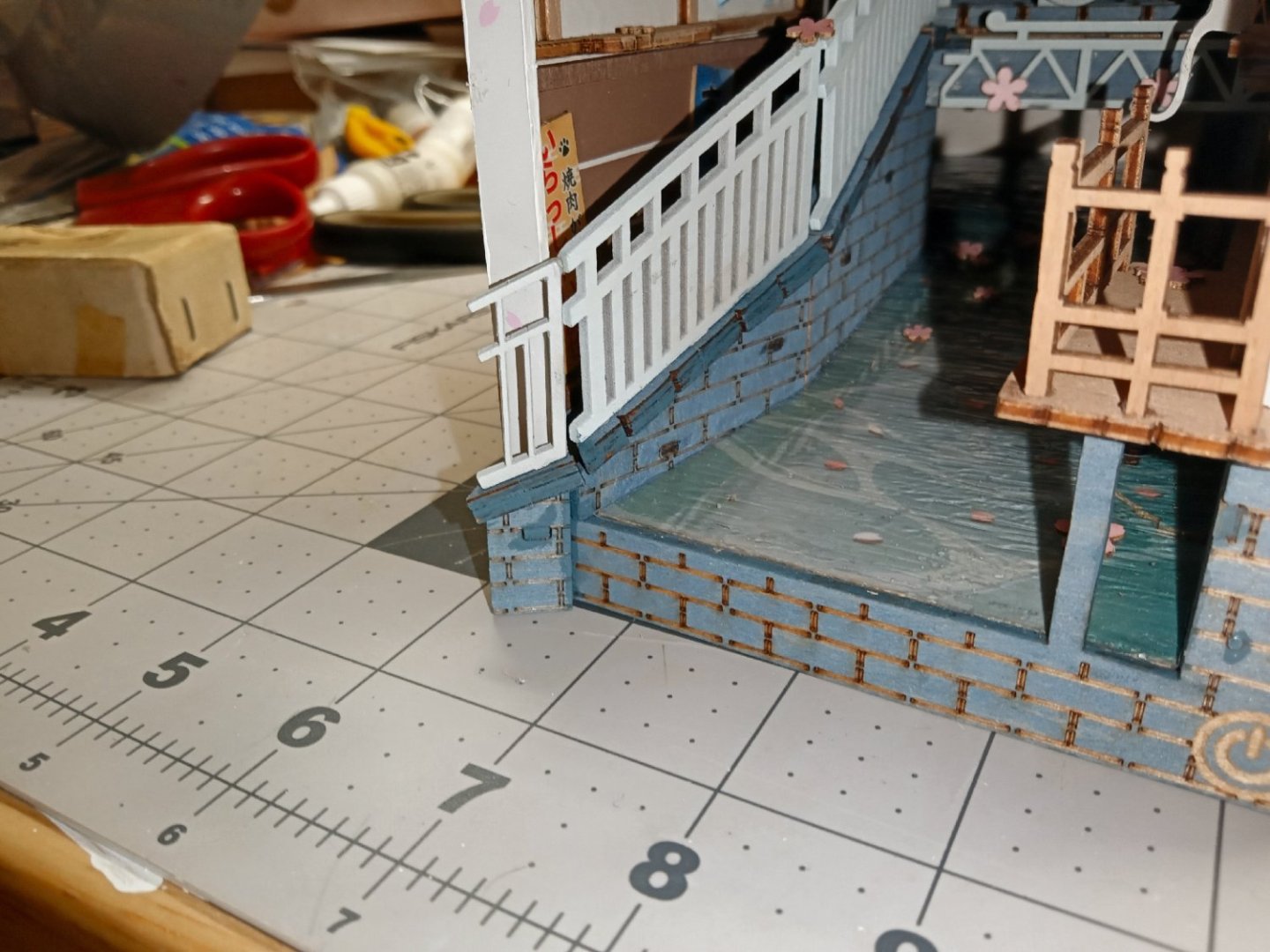
-
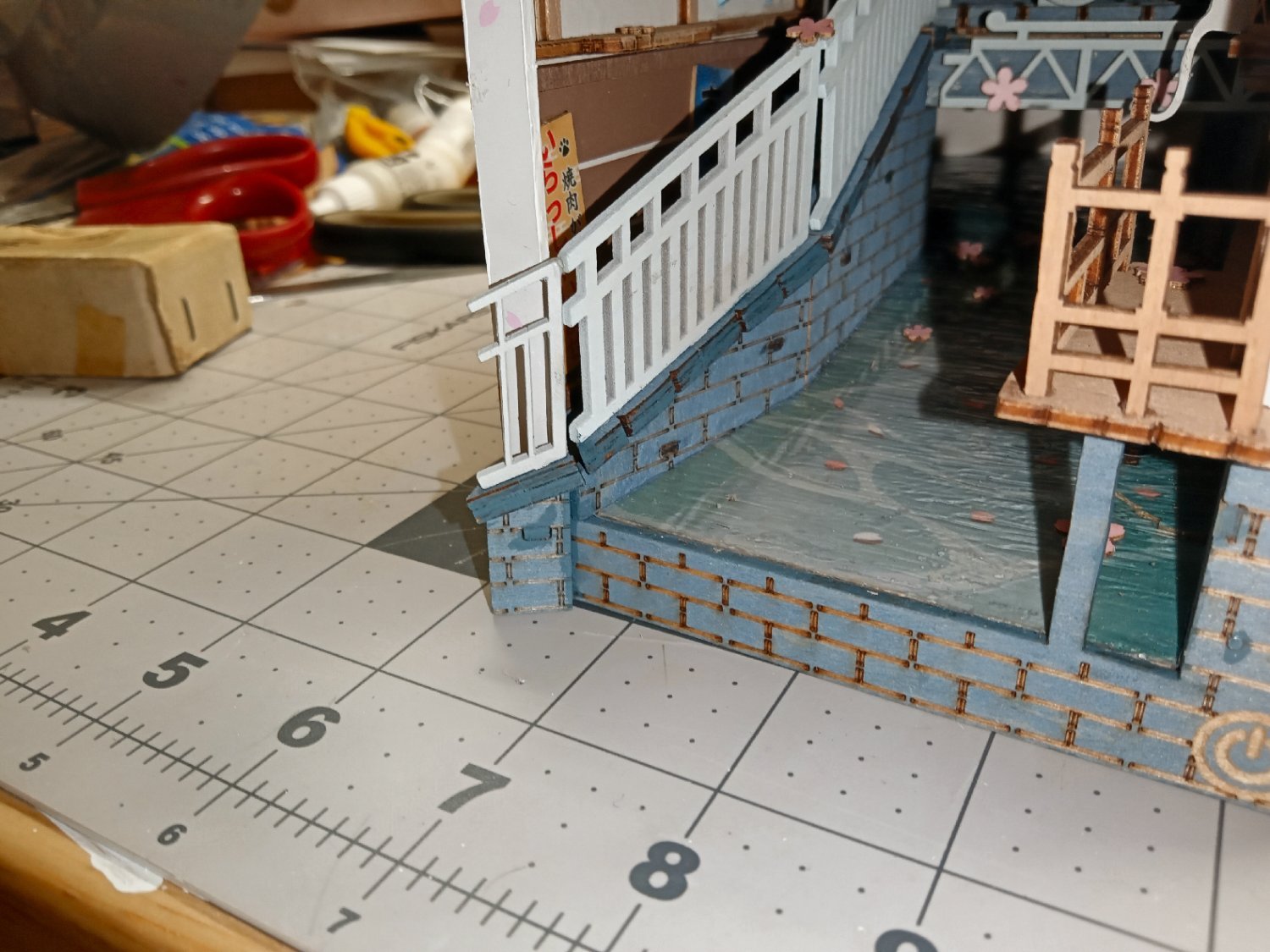
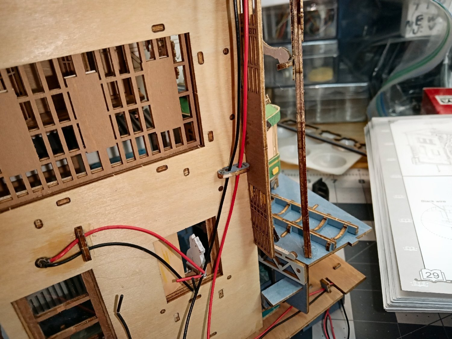
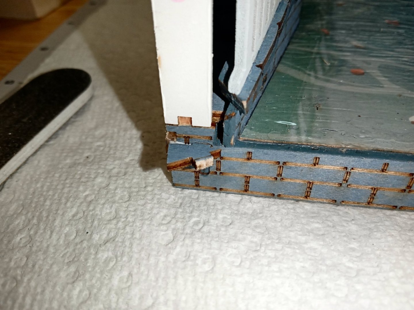
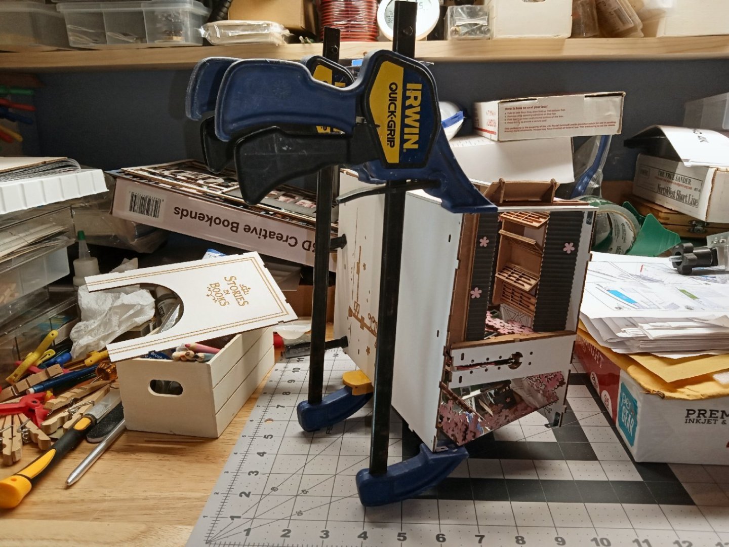
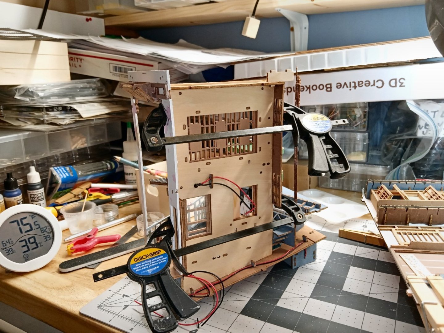
Part_018 The next operation is to install the left-hand side/book cover. When I test fit the wall, I found the gray wood trim strips interfered with the “stone” steps of the retaining wall mounted on the base. If you build this kit, temporarily install the wall and base with the retaining wall/steps attached, and then glue in these strips, so that they will not interfere later. After that continue with installing the other pieces, as per the instructions. There is room to move these and the brown wall trim up a little. I used the ruler to guide the hobby knife when I trimmed the bottoms off the strips. This picture shows the trimmed parts. I mixed another batch of the gray color paint, and painted the exposed edges. Next, I glued the front cover onto the right-hand inner wall, and the base, camping the parts to give a good fit. I then, fit the left wall, and also glued it to the front cover only, at this time. Once again clamps were used until the glue dried. After the glue dried, I connected the other tabs into the associated slots, and clamped the side until the glue dried. Here are pictures of the installed side. The wiring for the LEDs has to be connected, before the right-hand cover can be installed. First the wires for the LED in the top of the diorama are fed down through holes in the horizontal base of the LED support assembly. I decided to glue the wires into the slot, to prevent them from getting caught between the support and the top cover, when installing it. I glued them in place, then clamped them down, using scrap pieces of wood. I also used clamps as weights to keep the wires taut during the gluing and to help hold that end of the wires down in the slot. I installed the screw that secured the top corner bracket, between the left upper corner and front covers, while I was waiting for the glue to dry. The next step was to glue in another wire guide staple, and run the wires down through it. The instructions say to twist the wires together, then use the supplied tape sections to insulate the exposed ends. I soldered the wire ends, to make a good lasting connection, before adding the tape. This shows the taped ends. To make sure that the ends never touch, and keep the wires from interfering with the right-hand cover installation, I glued the ends to the inside of the inner wall. I added weights to hold them in place, and let it dry overnight. Here is a photo the next day.


-
3D Printing Cannons in Resin
thibaultron replied to thibaultron's topic in 3D-Printing and Laser-Cutting.
Not all 3D resins are brittle. If you need a more durable resin for a project, here is a link to a model railroad Podcast, where one of the members is 3D resin printing an entire HO scale diesel locomotive, and discusses the durable resins he uses. He crushes and earlier print with a standard resin with his fingers. He then shows the more flexible body he printed with the better resin. The discussion starts at about minute 25. He used: Siraya Tech Fast Resin for body, which is a bit flexible, and their Blue Resin for the gearboxes for the power trucks. The Blue is strong, but stiffer, as is needed for a gearbox you want not to flex. -
Laser cannon bracket
thibaultron replied to mediocremodeler's topic in CAD and 3D Modelling/Drafting Plans with Software
Ive drawn several types and sizes of cannon, and posted the STL files on this thread, if you are interested. -
3D Printing Cannons in Resin
thibaultron replied to thibaultron's topic in 3D-Printing and Laser-Cutting.
The only drawing I have for the carriages is this one. Armstrong Frederick Pattern 1760.DXF I've been concentrating on the cannons. -
3D Printing Cannons in Resin
thibaultron replied to thibaultron's topic in 3D-Printing and Laser-Cutting.
I'm about 3/4s of the way through the Borgad cannons. Here is a graphic of one of the 12 Pounders. Here is a closeup of the King George 1st cypher.
-
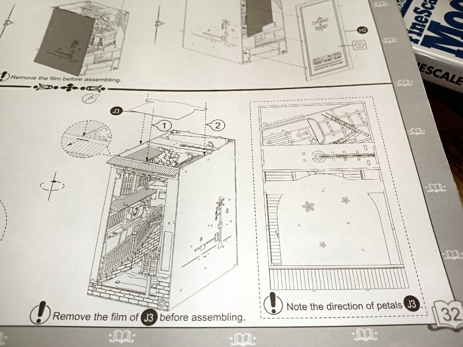
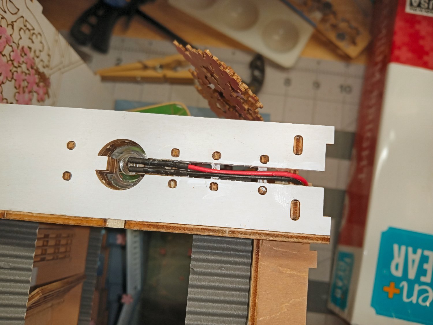
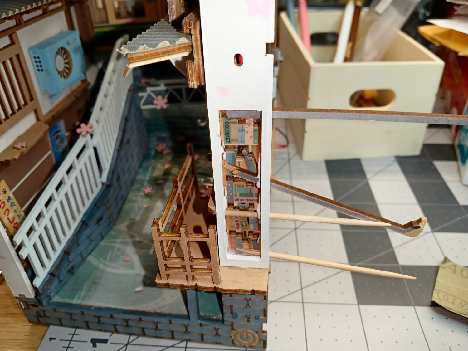
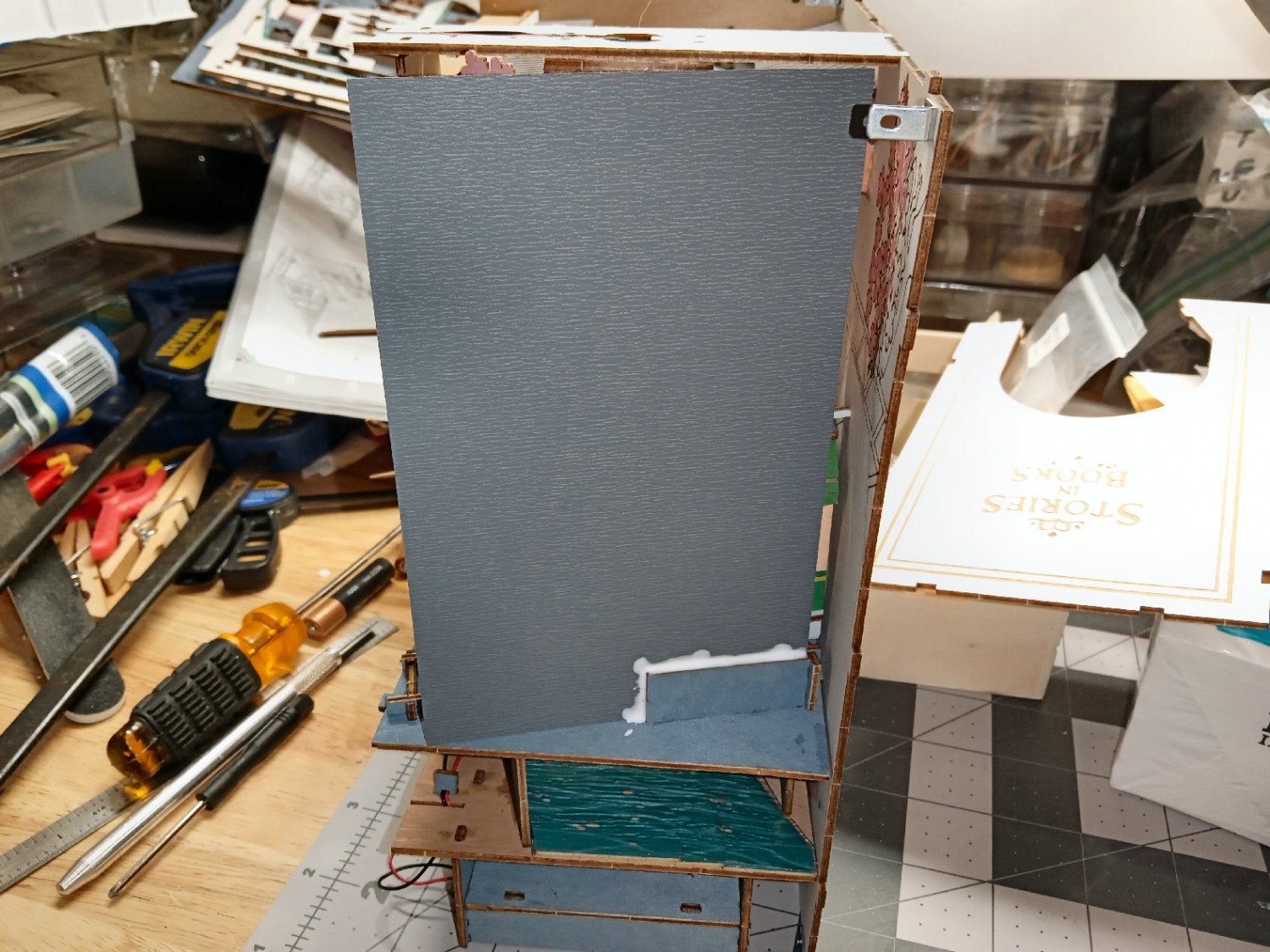
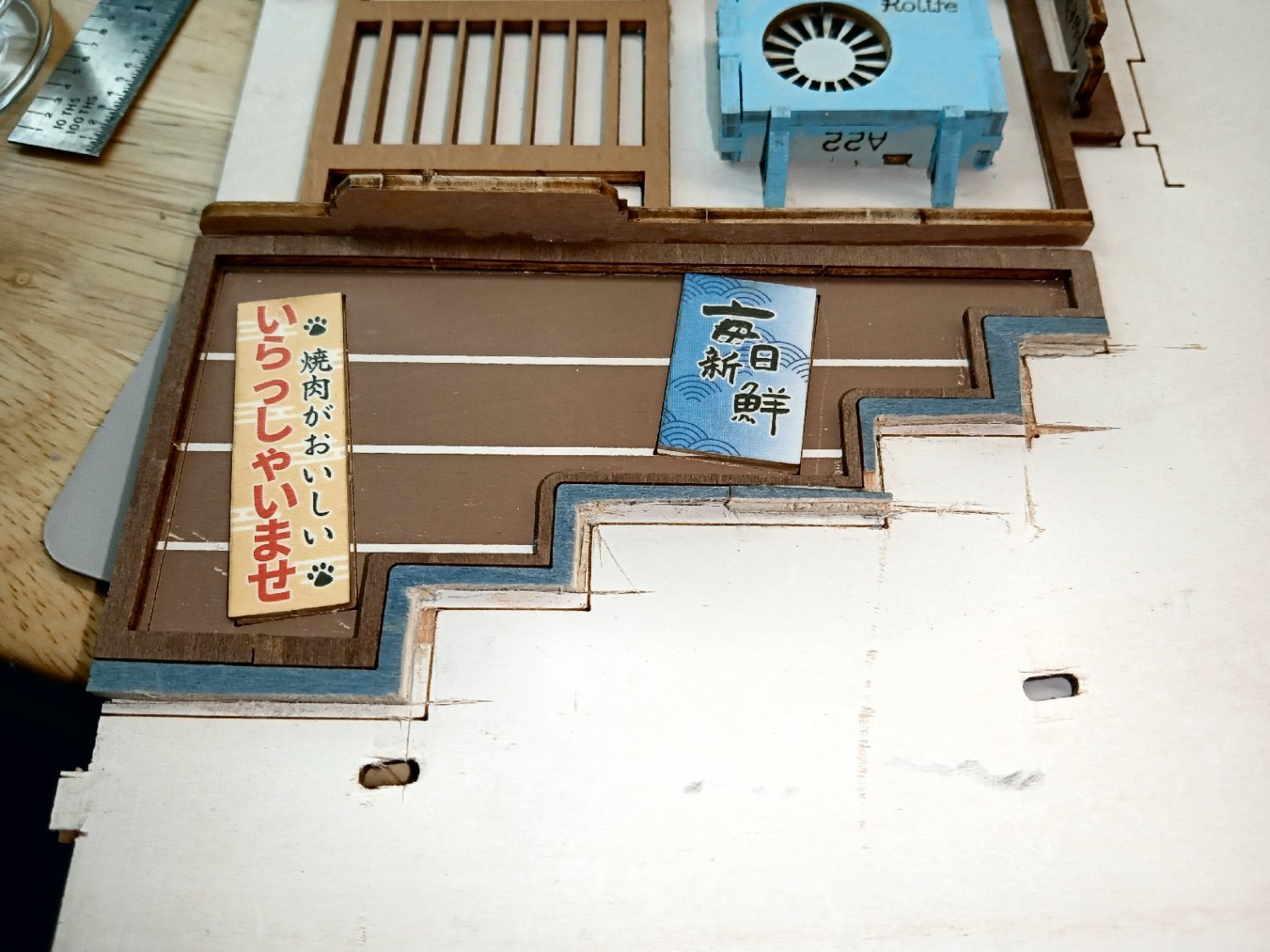
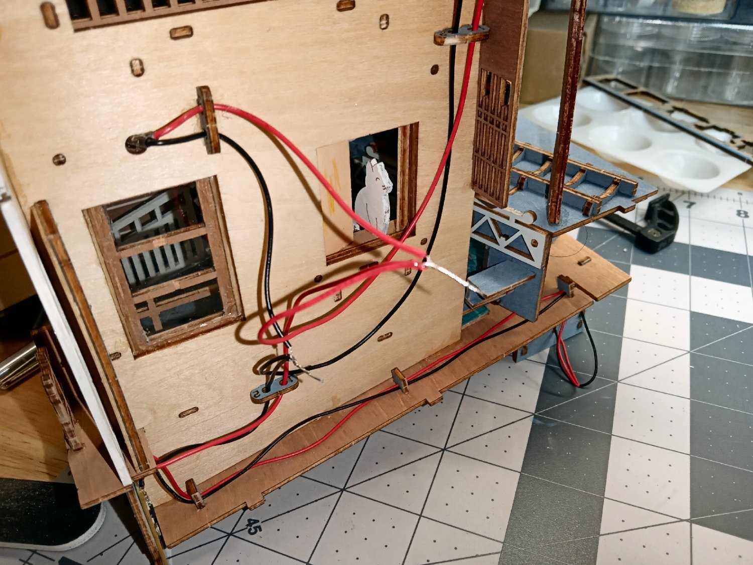
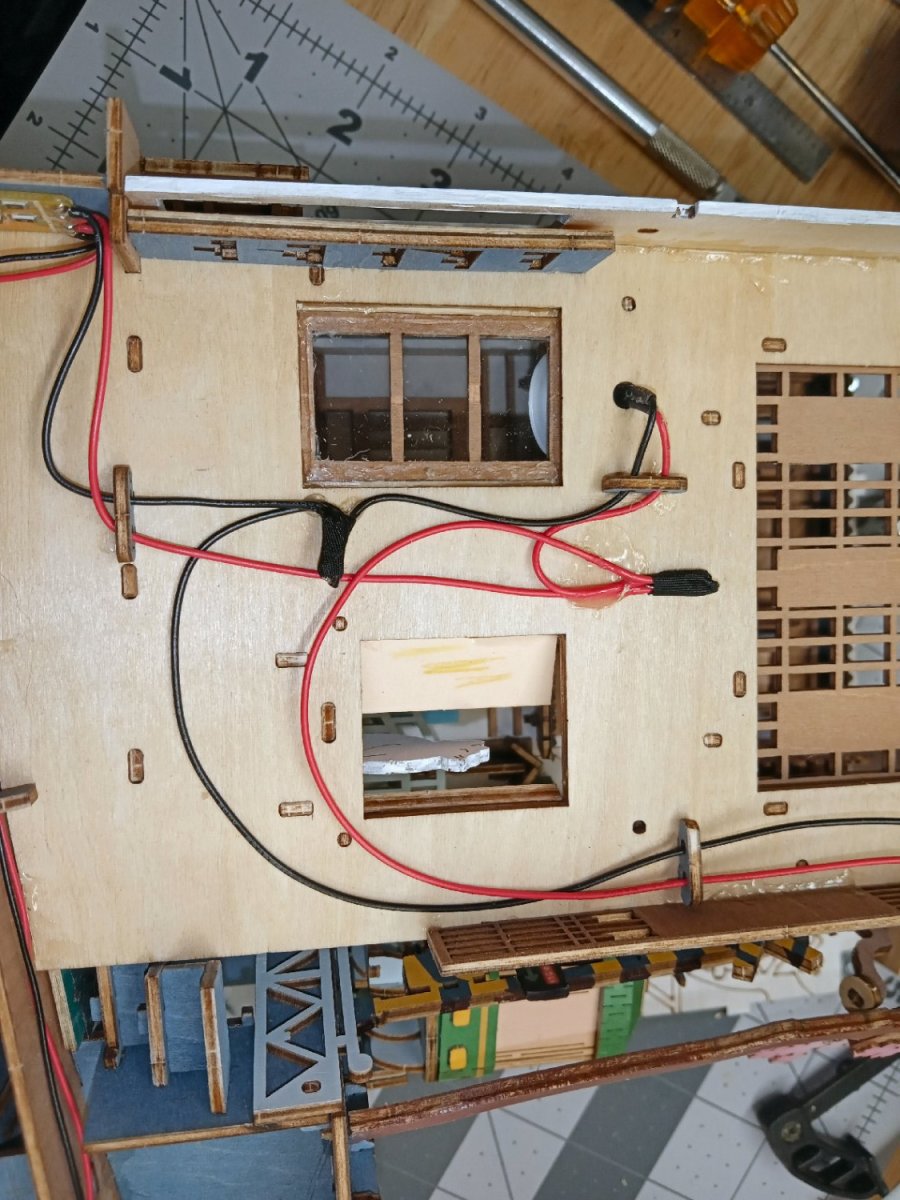
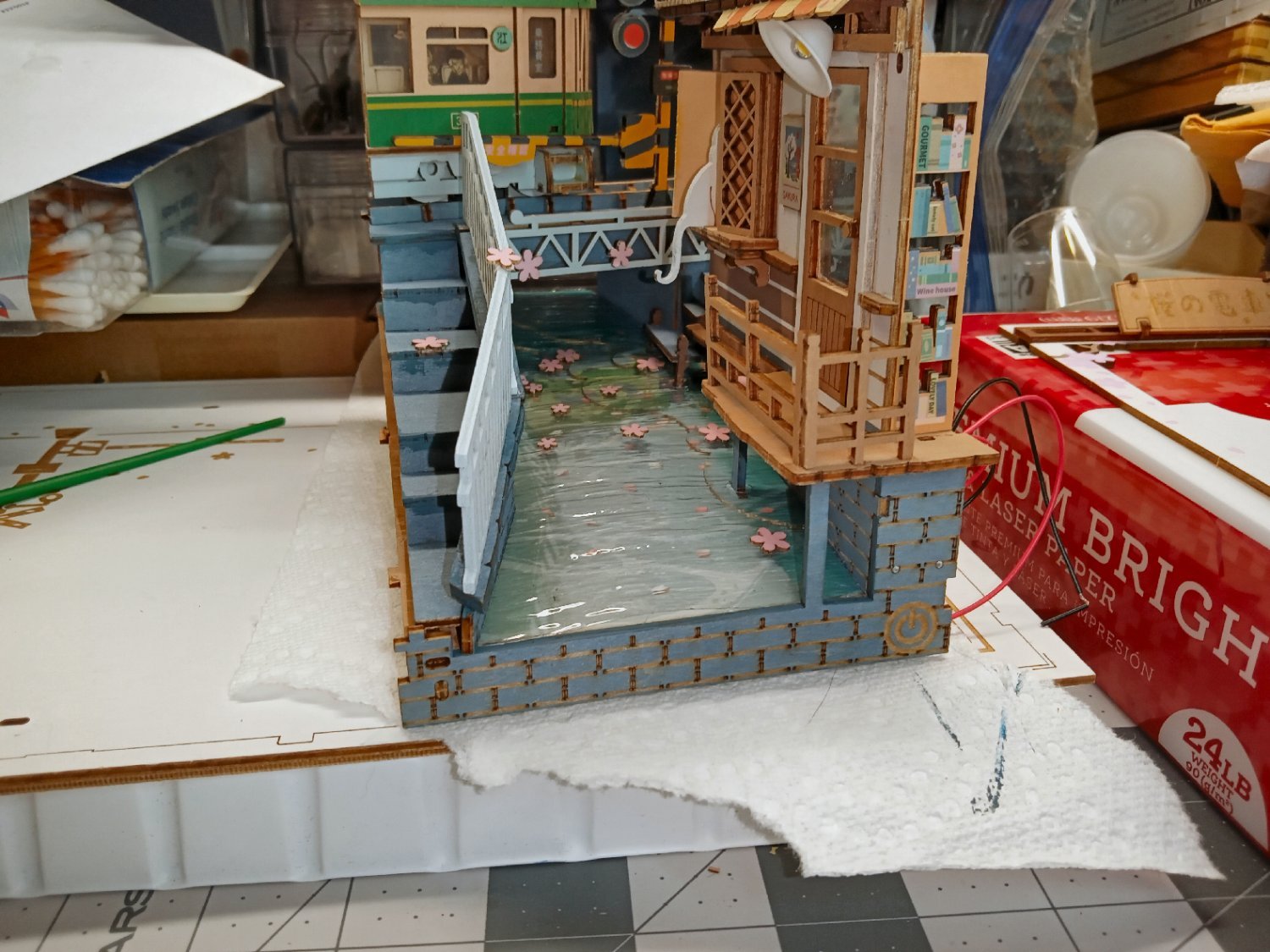
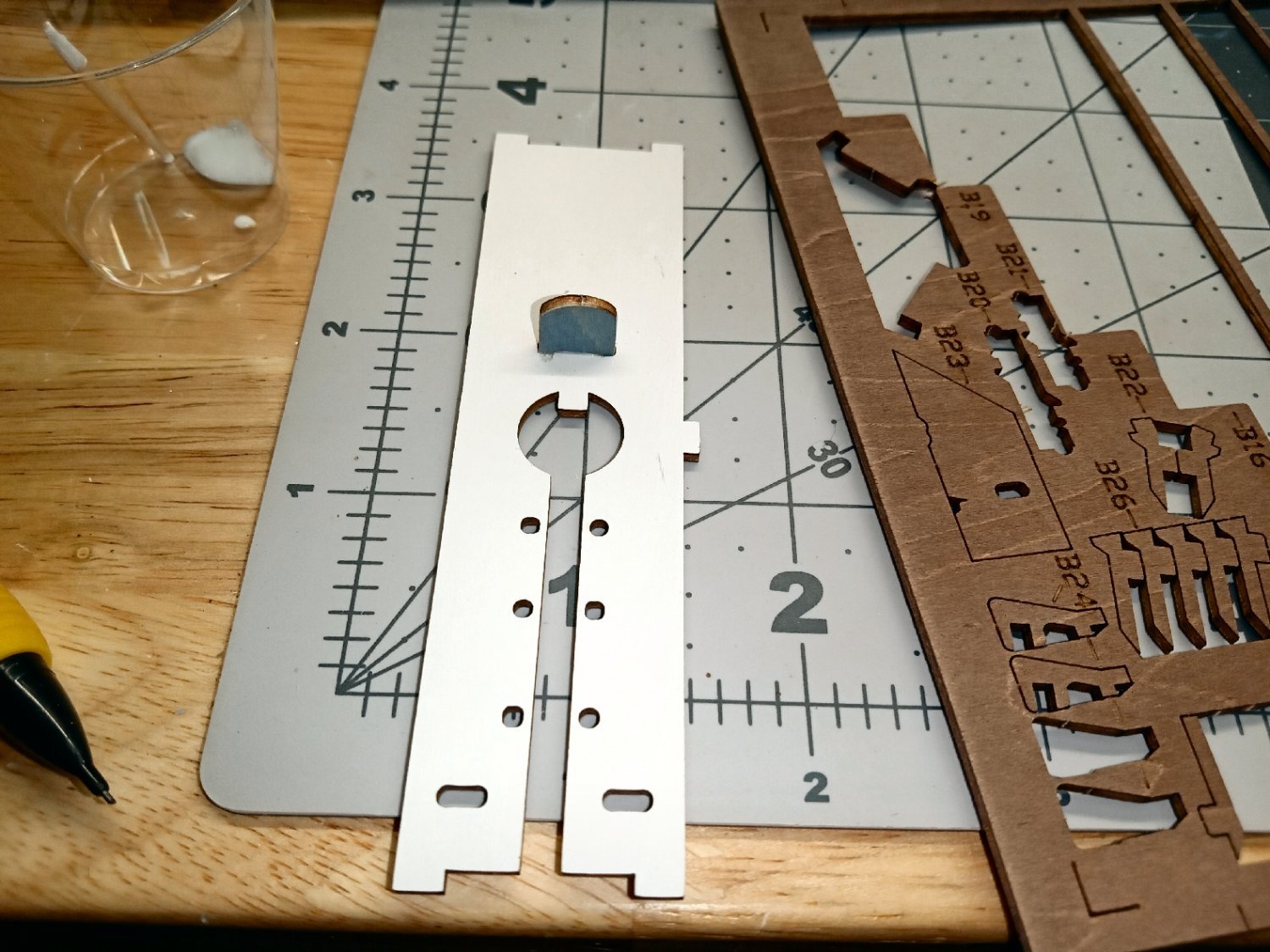
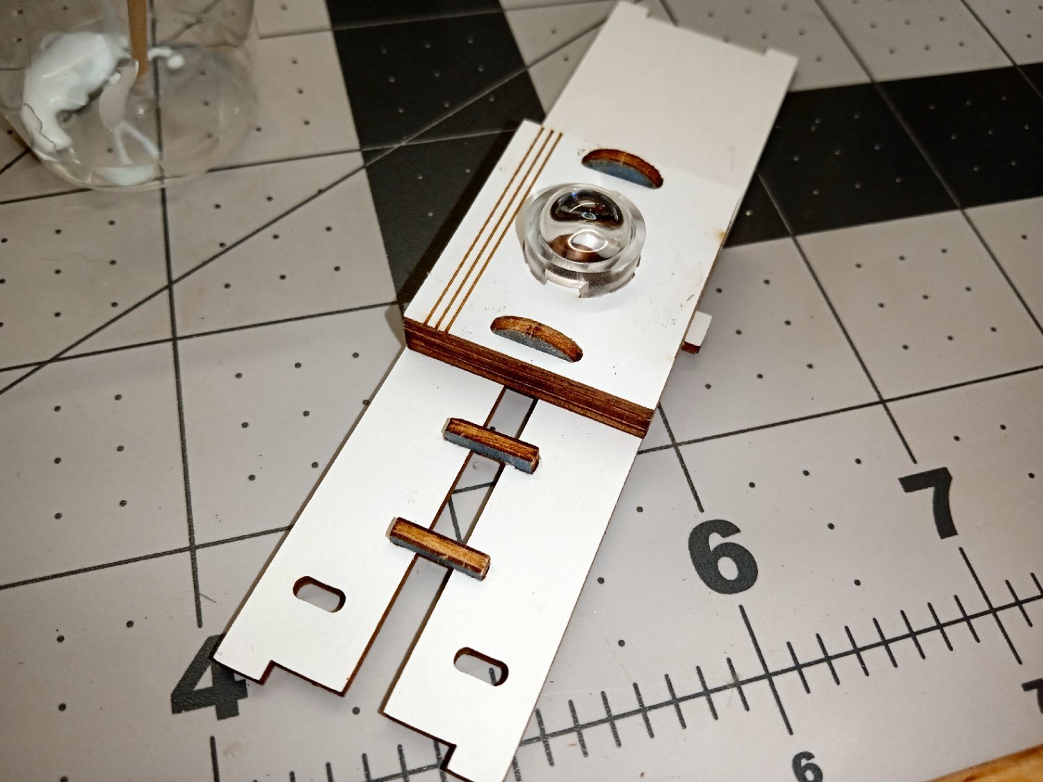
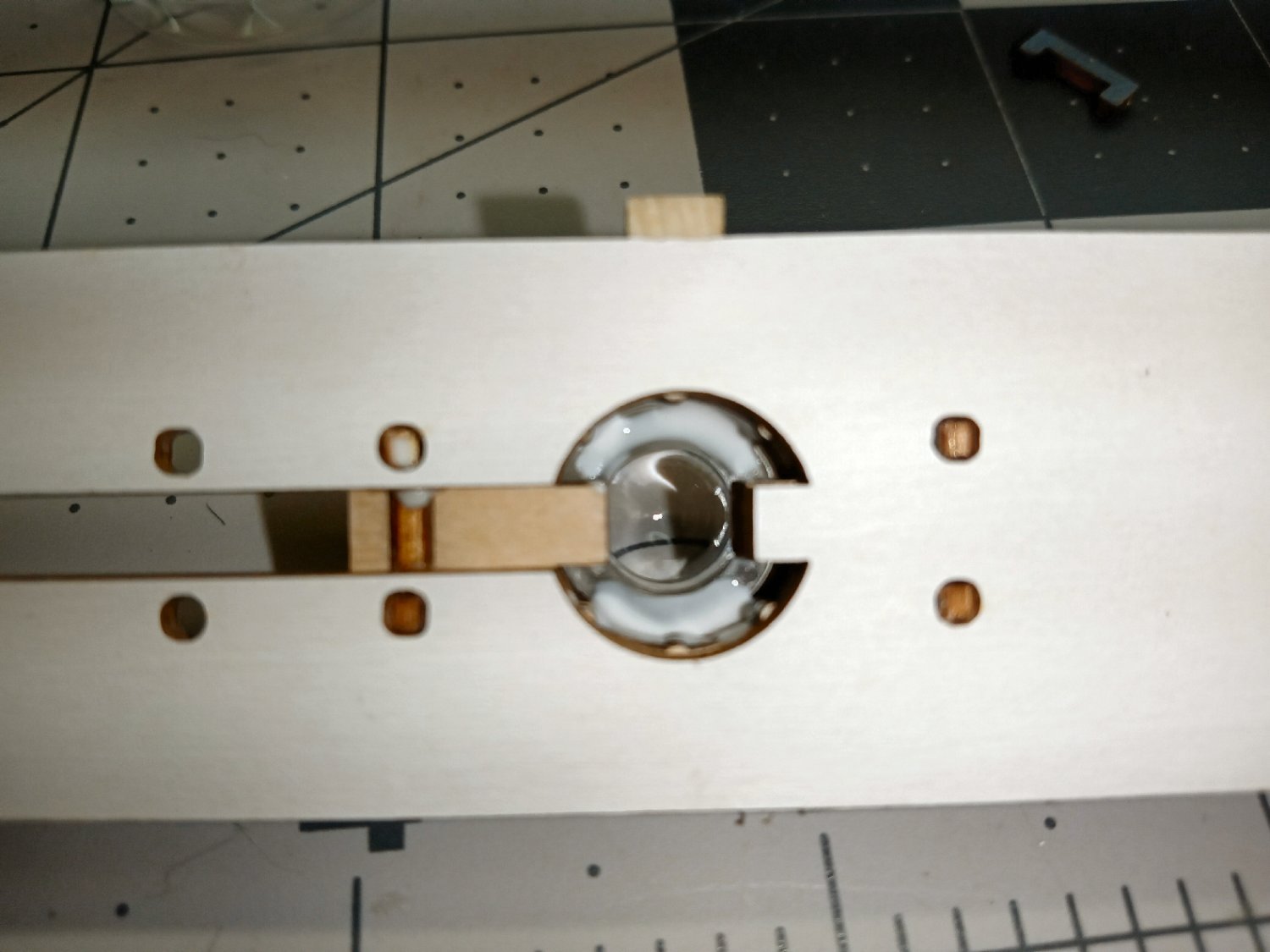
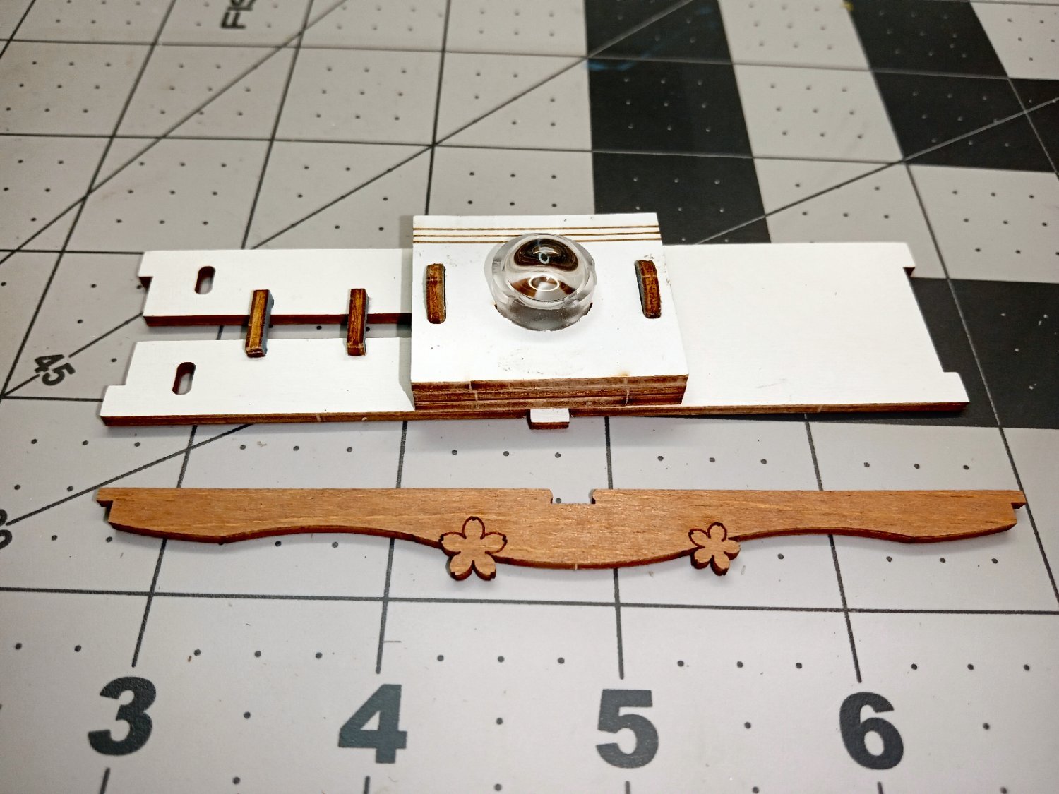
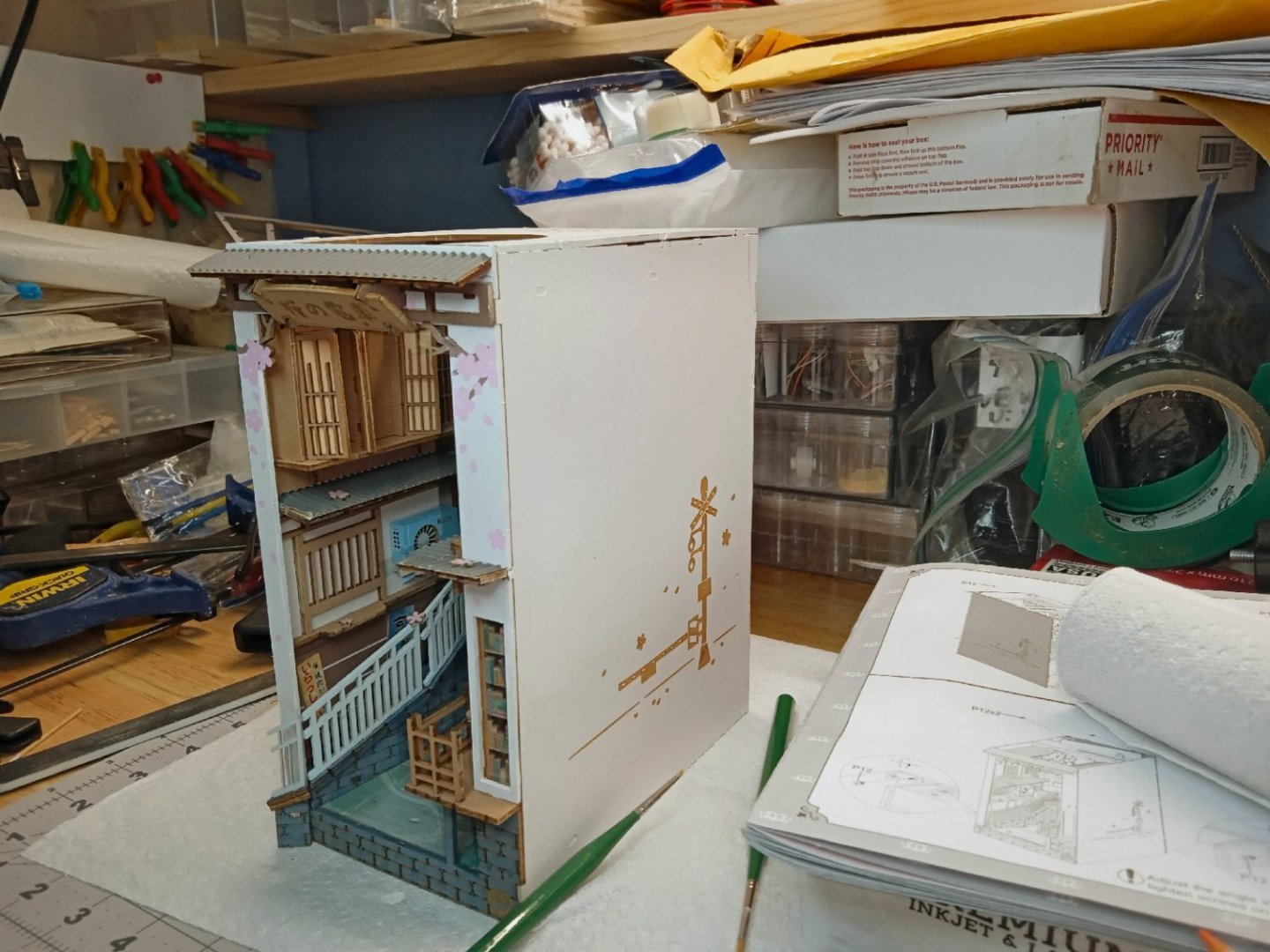
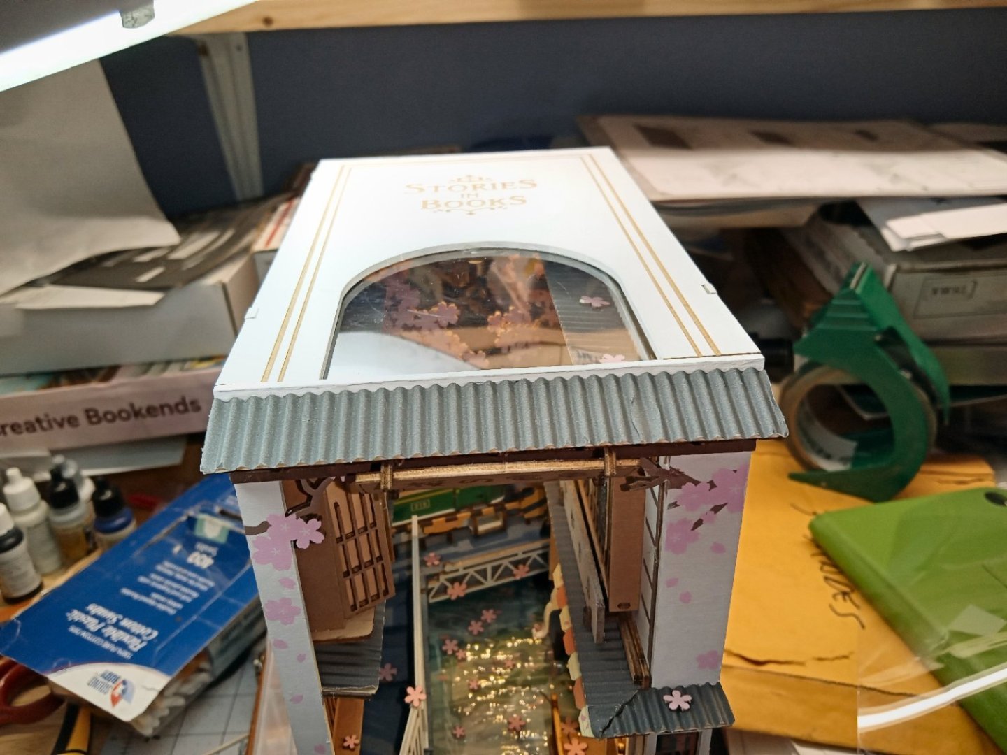
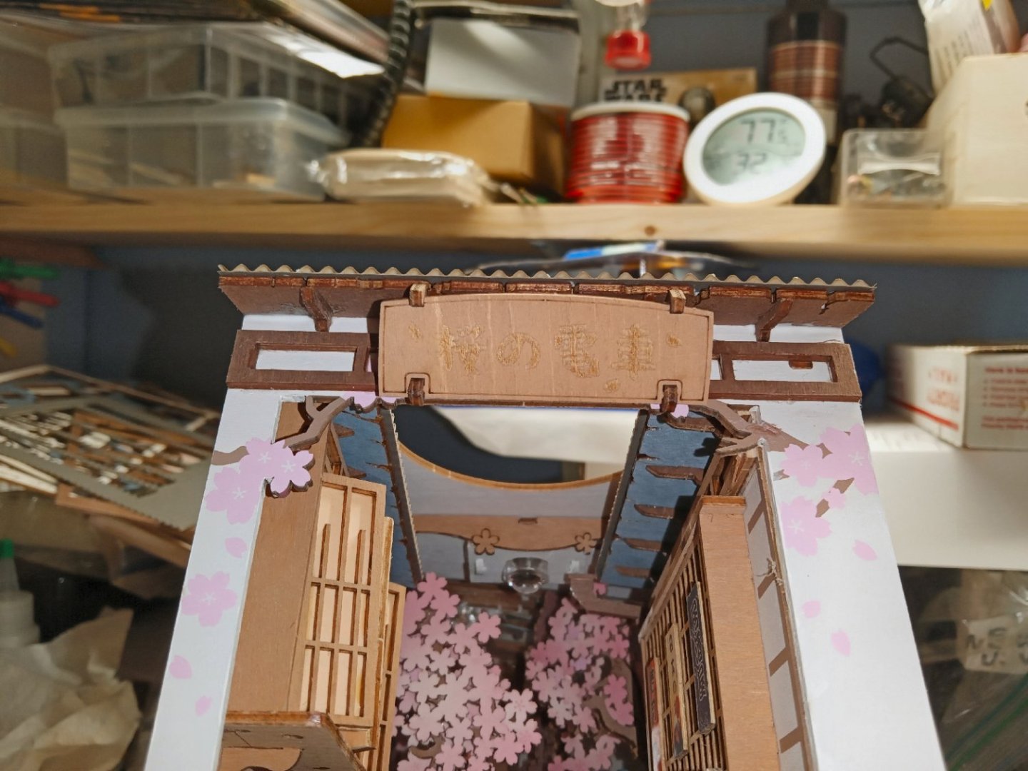
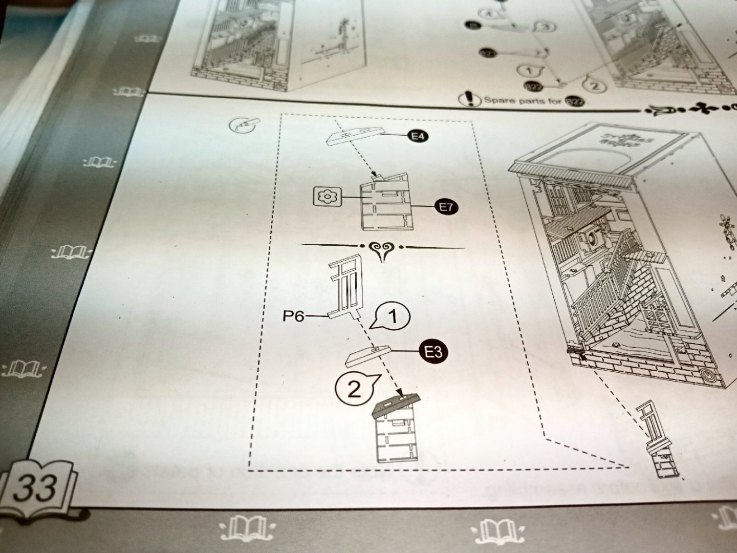
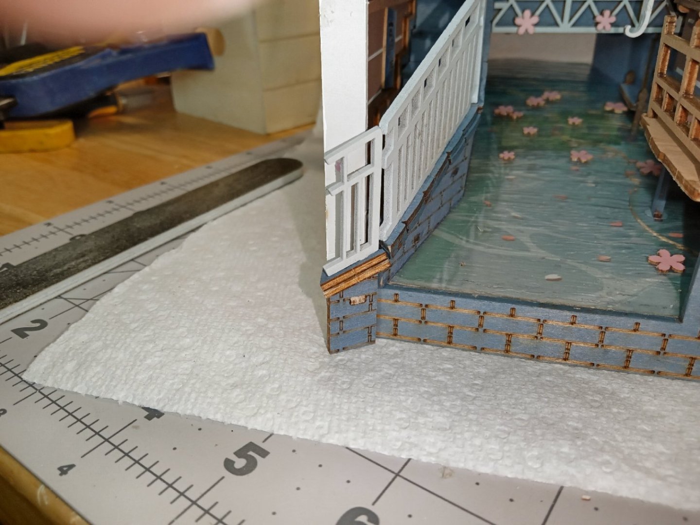
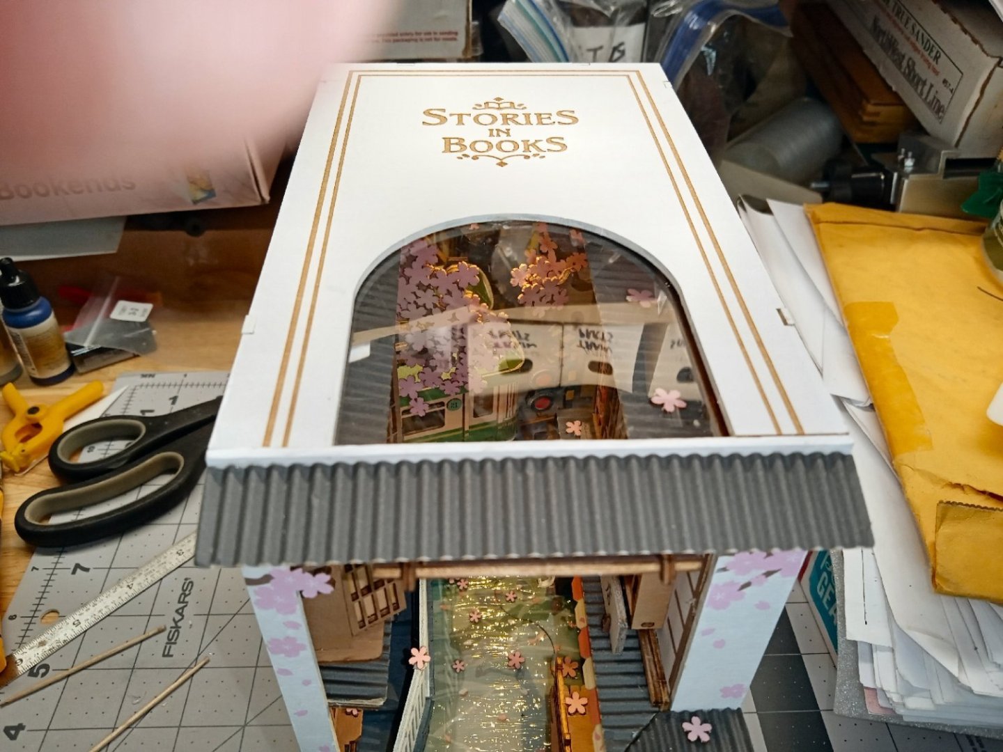
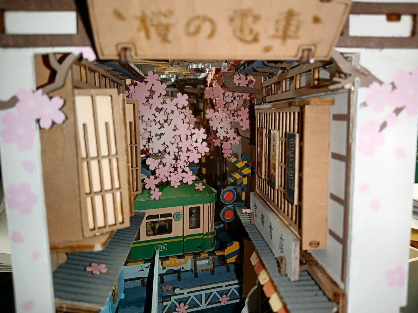
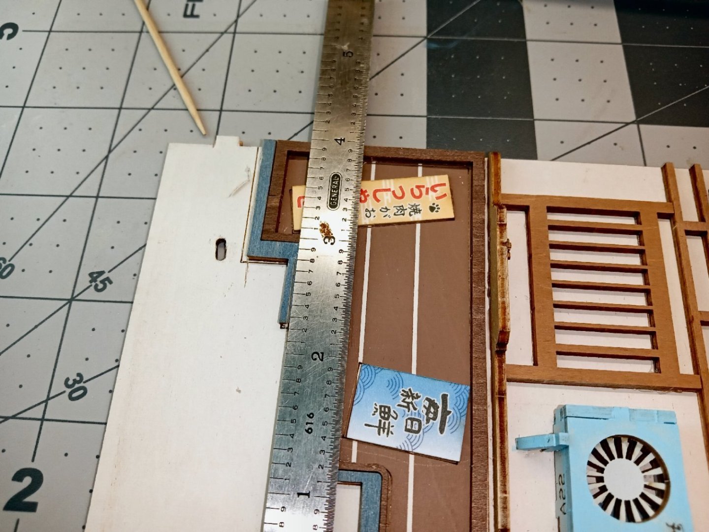
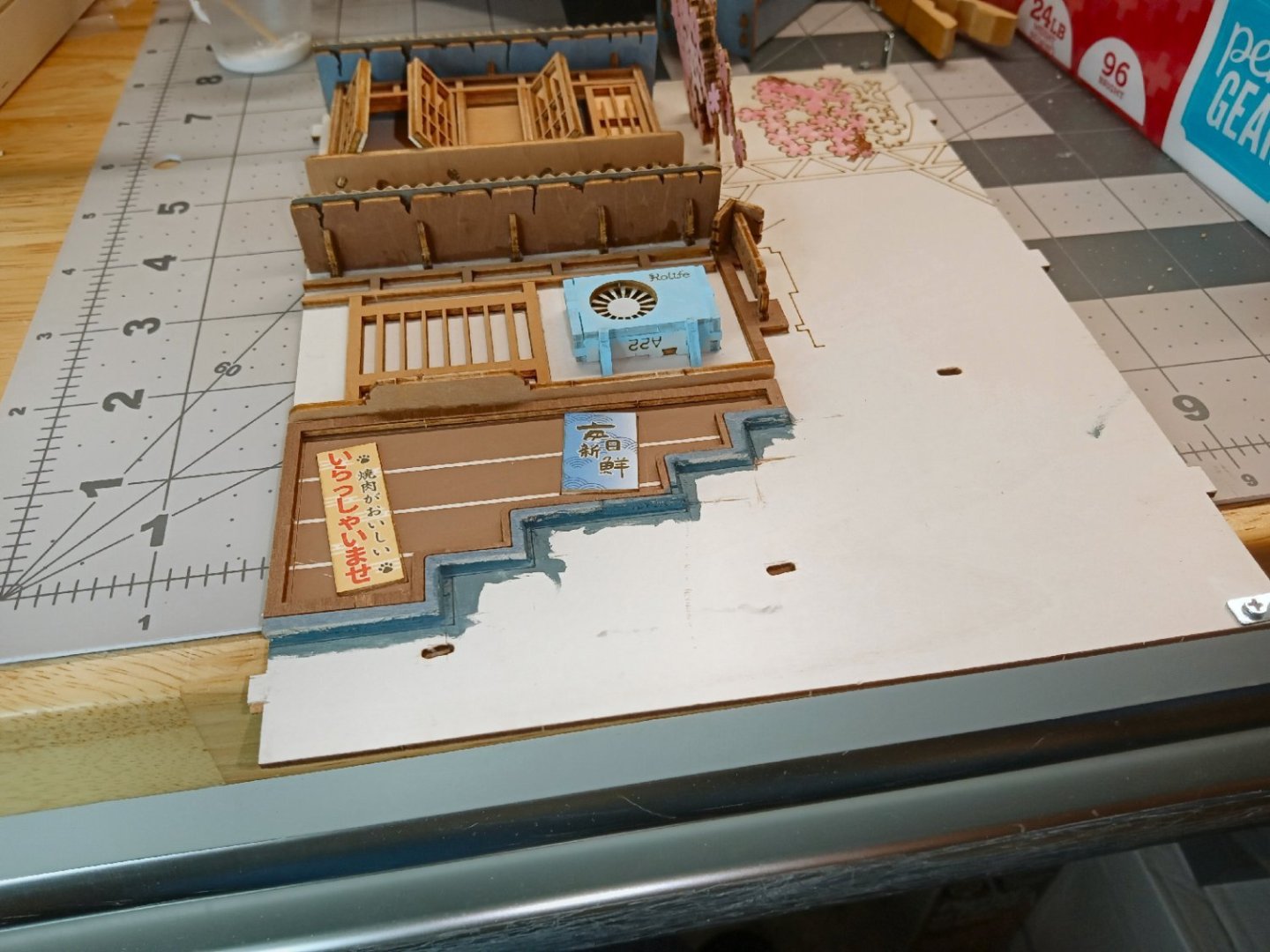
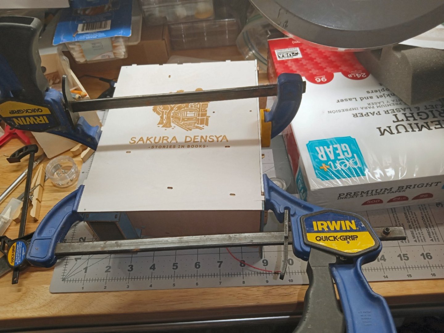
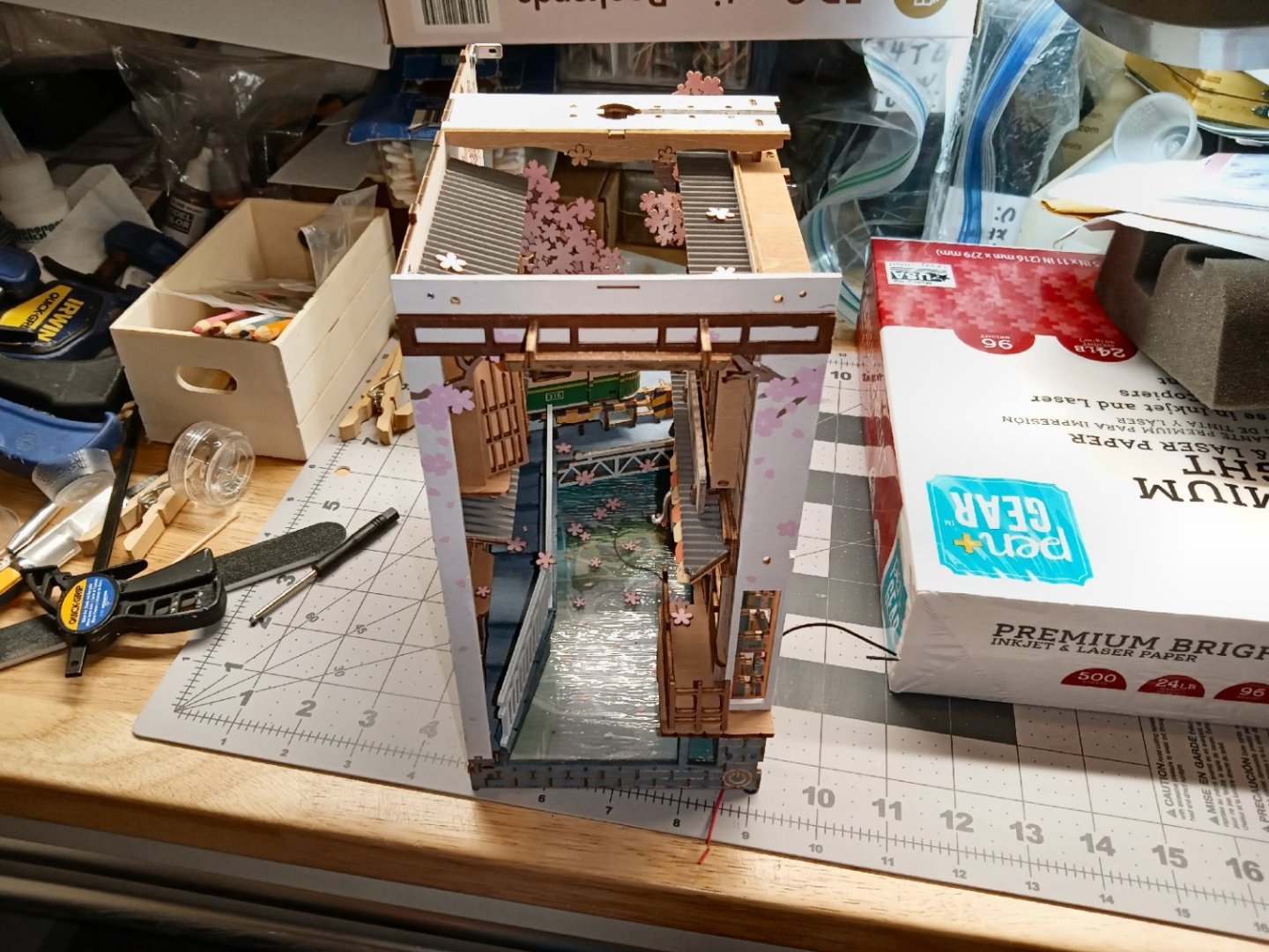
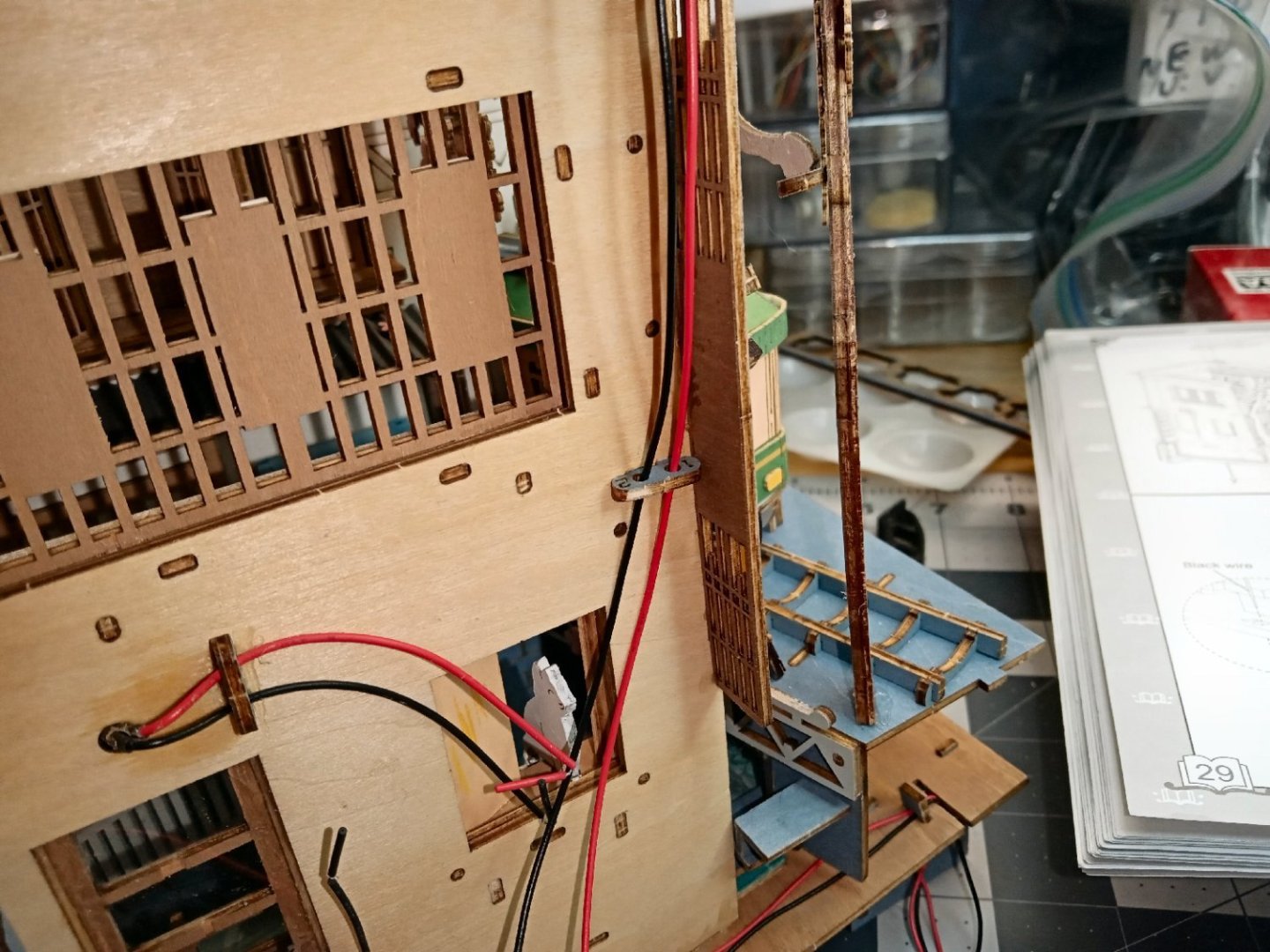
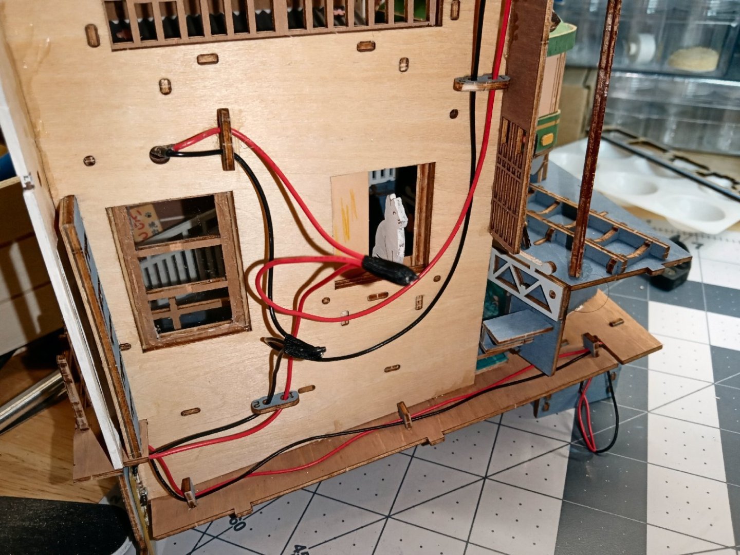
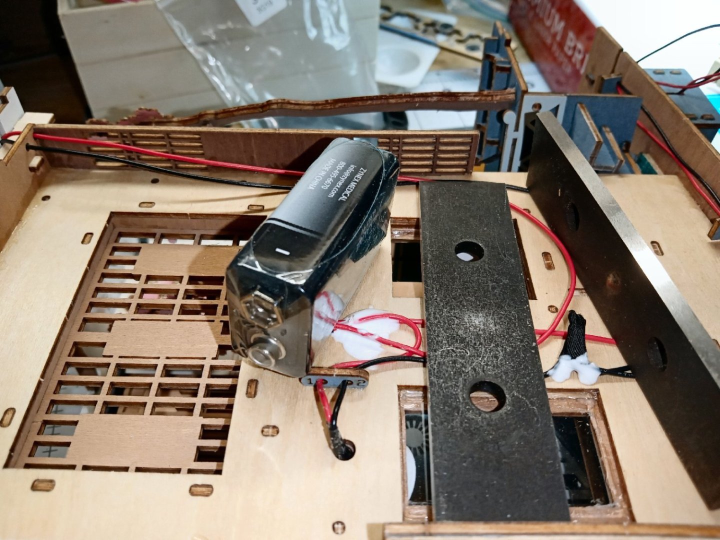
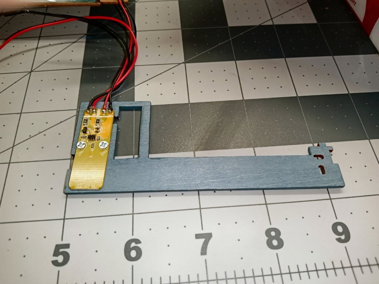
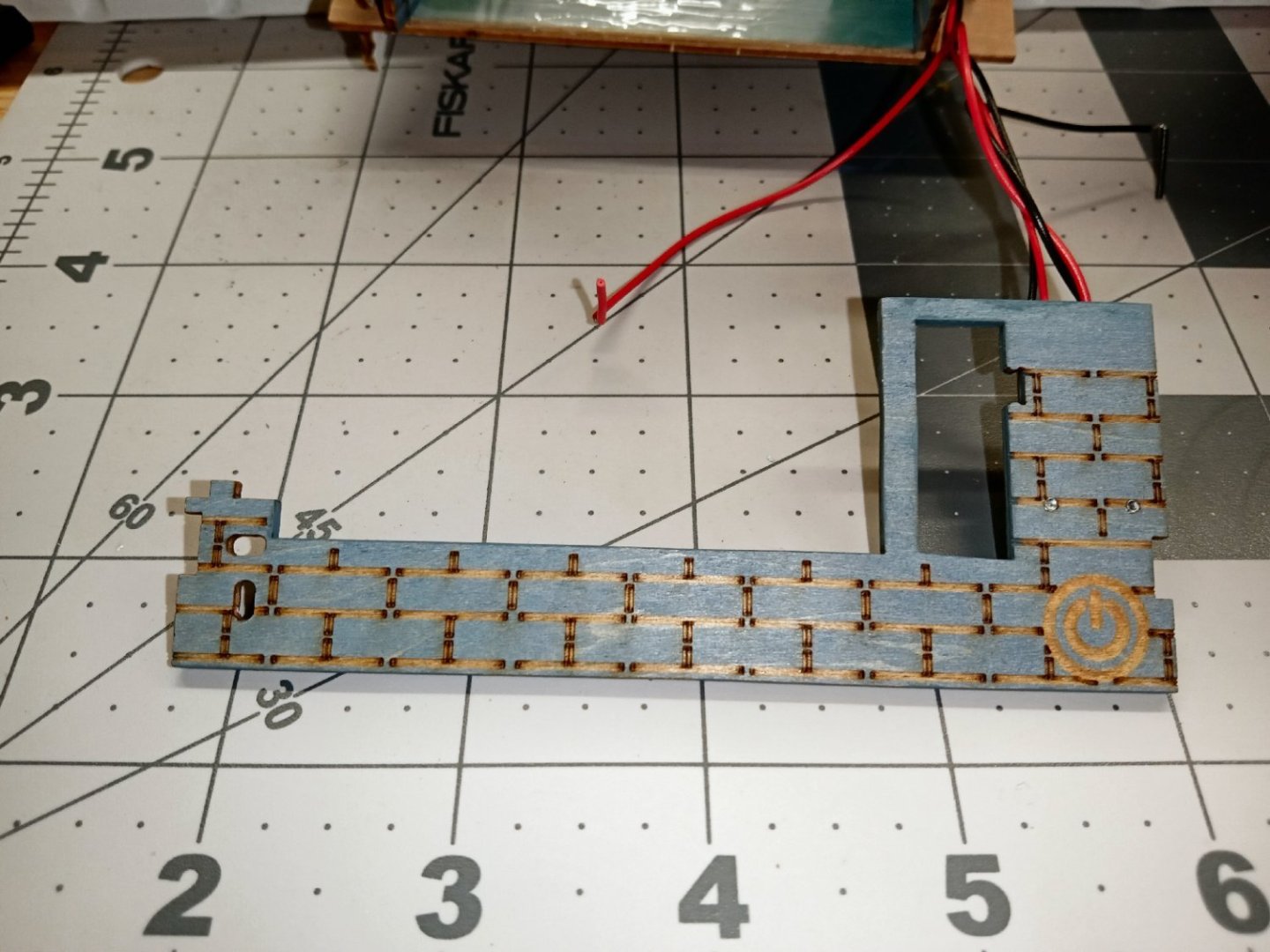
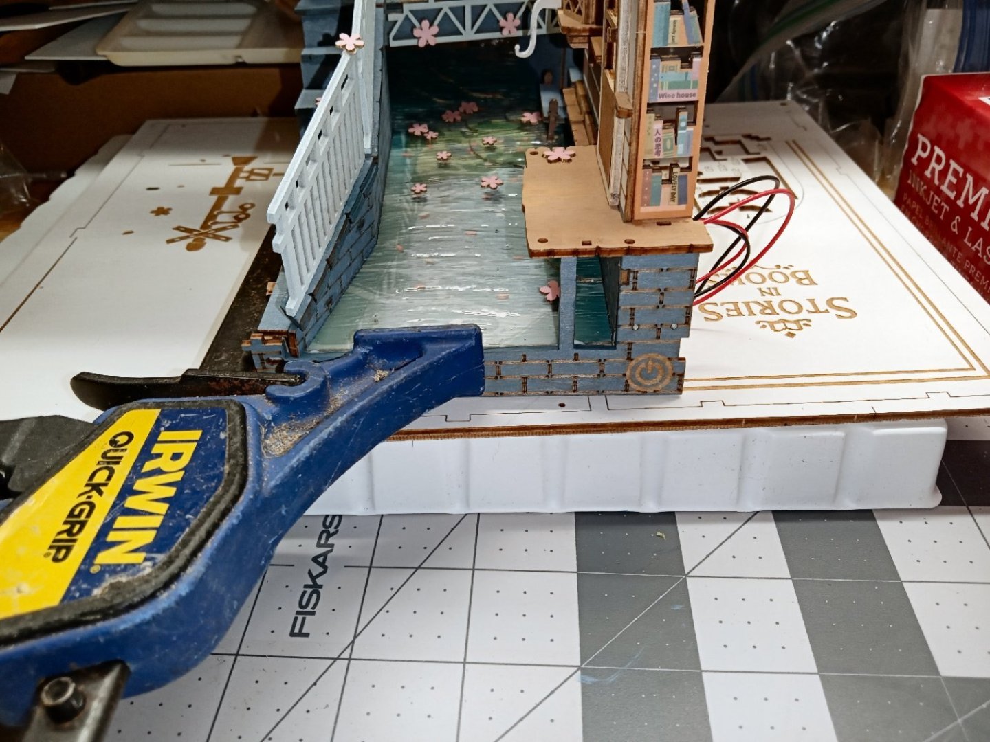
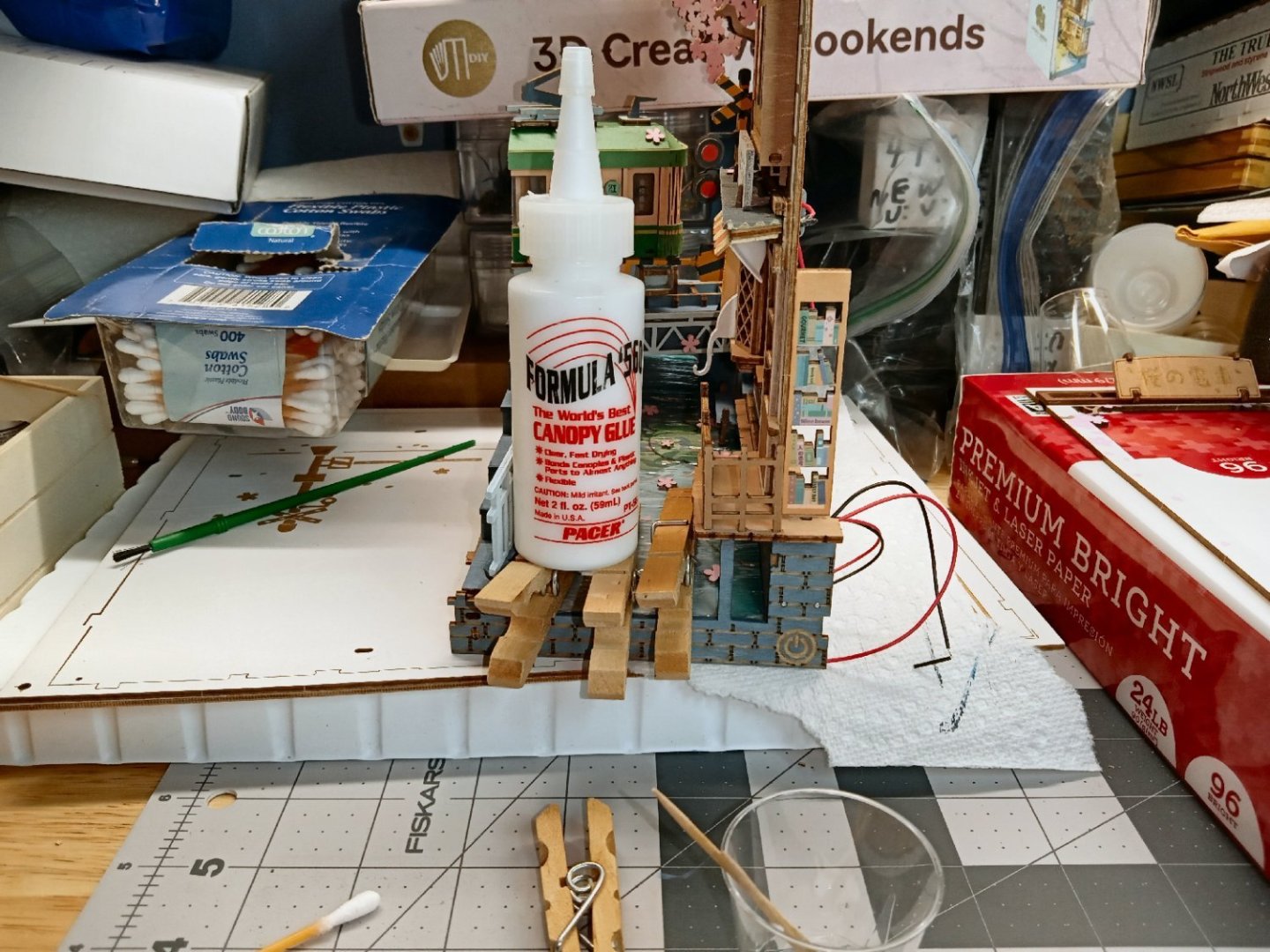
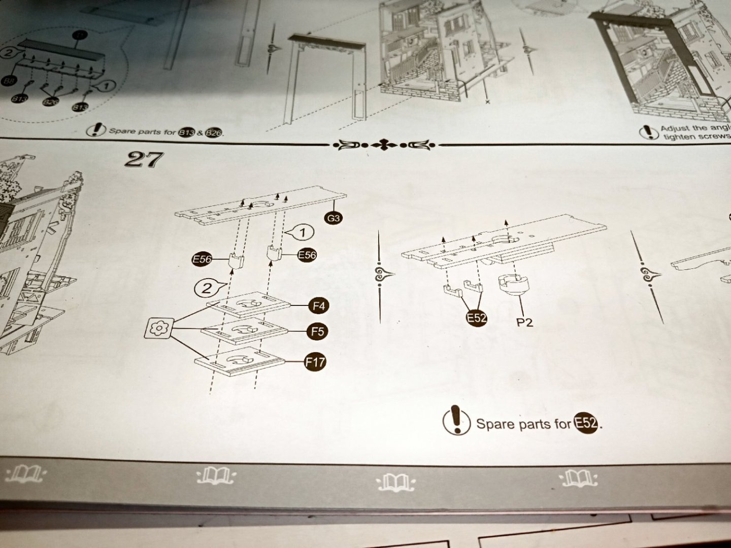
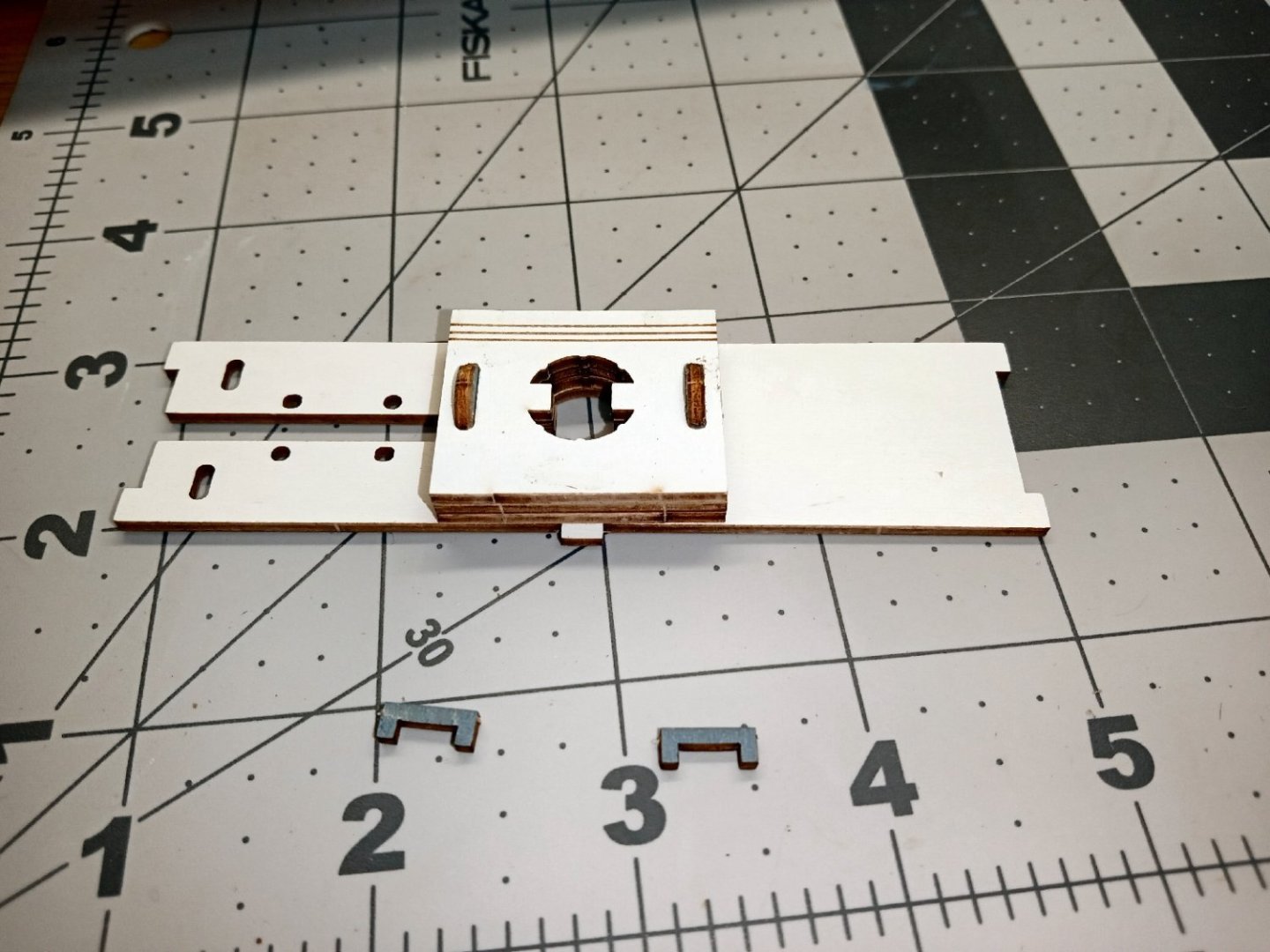
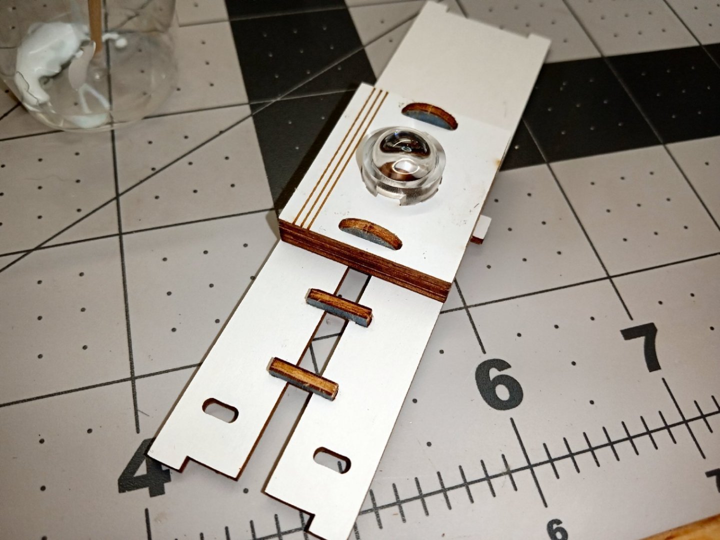
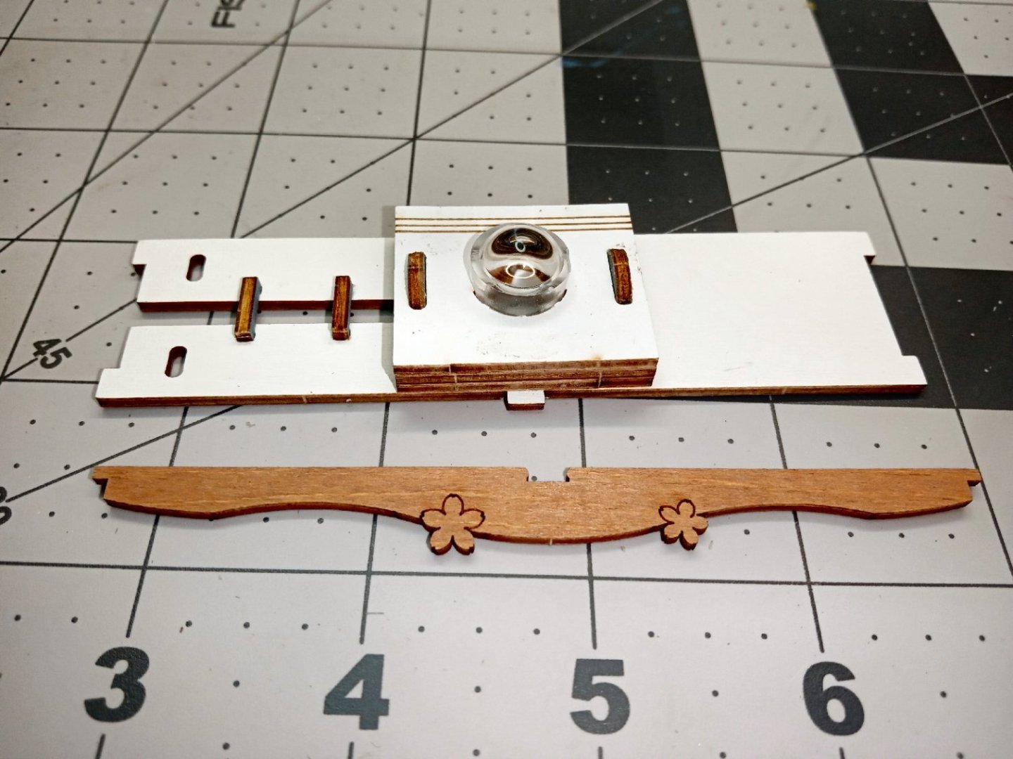
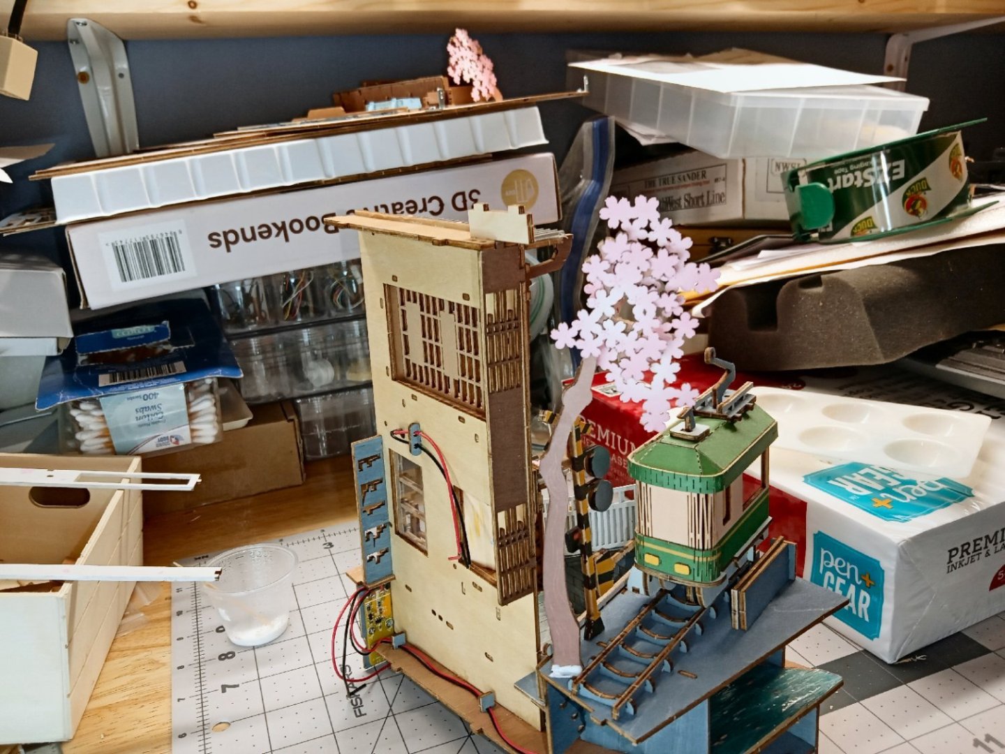
Sakura Densya “Cherry Blosom Train” Part_017 Before the front masonry piece is installed, the LED power switch circuit board has to be screwed on. Here is the part installed. I had to use one of my regular sized clamps to hold the streambed edge of the part flush with the stream, until the glue dried. The front to back length was too long for my modeling clamps. This shows the progress so far. As I have had ant problems in the shop, I glued the plastic water piece down along the front and back, to make sure they don’t get under there if they show up in the future. I used the clothespins to spread the weight of the glue bottle, to hold the edge down while the glue dried. The weight of the clothespin on the far right was enough to hold down that section. It turns out I was wrong in an earlier post; the model does have a second LED. It goes at the top of the model, in a dedicated holder. Construction starts with a base that spans between the left wall and the inner right-hand wall. The base has two wood staples that align the three center standoffs that the LED lamp globe attaches to. This shows the base with one of the staples installed. The photo shows the base and three standoffs glued together. The top standoff is shown being installed with the colored side facing toward the base, but I decided to leave the colored face exposed. The part is symmetrical, side to side, so the parts still line up. Next two more staples are installed to hold the wires that go to the LED. The LED globe is designed as a press fit, but I added glue between the globe and standoff, on the inside, to make sure it stays in place. To hide the LED support, there is a faceplate installed I had to clamp it in place while the glue set. I used the clothespin clamp for the section that had the slit for the wires. Hard clamping this across the slit risks breaking one of the arms off. I broke an Atlas lathe belt tensioner assembly a couple of decades ago, making that type of mistake. Luckily, I was dealing with a used machine tool dealer, back then, that sold me a whole newer, better designed, belt tensioner assembly for a reasonable price. After the pieces set, I panted the colored areas and the staples white, to hide all the raw edges, just in case any of it is visible in the finished model. There are two support pieces for the LED assembly that need to be glued to the right-hand inner wall. I had glued and clamped these in place, then found much further back in the instructions, that there was a trim piece that locked into this support! The glue had set already, and the clamps had distorted the support slightly up at the back. I had to break the glue joint and then install the trim piece, then reglue everything. In my defense that trim piece was rather hidden in the instructions, still I should have checked. The piece is the lattice work part on the right of the pictures. I painted the raw edges of the upper front face piece white to match the color of the part. It took three coats to fully hide the edges, on this majorly visible area.


-
What kind of Cutting Mat choose
thibaultron replied to Olaf's topic in Modeling tools and Workshop Equipment
Just about any type of the self-healing mats will work, In the US they are available from craft stores, and Walmart. Generally they are in the sewing section. Hobby stores should also carry them. My present one is 12X18". I also have a thick plate glass ex-shelf, that I use. This tends to dull my blades quicker than the plastic mats. It does make a good flat surface for assembling models though. The glass plate is also nice, in that you can slip a drawing under it, while modeling for reference. No worry about damaging the drawing, or photo, while also making sure it stays in place.