thibaultron
-
Posts
2,634 -
Joined
-
Last visited
Content Type
Profiles
Forums
Gallery
Events
Everything posted by thibaultron
-

CNC Desktop Router Reviews
thibaultron replied to tmj's topic in CAD and 3D Modelling/Drafting Plans with Software
I use SketchUp for my 3D work. As long as you can create STL. or OBJ. files you can use the output for the CNC. -
CNC Desktop Router Reviews
thibaultron replied to tmj's topic in CAD and 3D Modelling/Drafting Plans with Software
You mat still want to build an enclosure, though. The routers create a lot of dust! I have a write up on the one I built for my machine stsrting on this thread page. -
CNC Desktop Router Reviews
thibaultron replied to tmj's topic in CAD and 3D Modelling/Drafting Plans with Software
To use the laser, it is critical to buy or build a case for it!! The laser can reflect and injure you or more specifically your eyes!!! There are laser safe tinted sheets that can be used as windows, so you can view the process. These lasers while "Low Power" compared to industrial ones, can still cause burns and eye damage. When designing or buying a case, allow for the table or work piece that will extend past the frame at each end when at full travel. -
Your welcome.
-
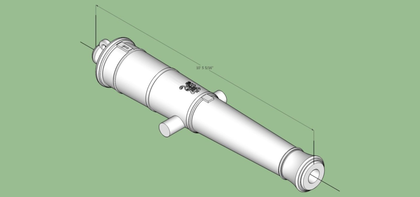
In a thread I can't location now, there was a request for the correct size cannons for a cross section model. The consensus was that the ones supplied in the kit for the George the 3rd Blomefield 32 Pounder cannons were the wrong length. I have been working on CADing the entire series of this type and bumped the 32 Pounder to the top of the list. Here is an STL file for the full sized cannon. You will have to rescale it for your needs. I have also included two graphics showing the final 3D design. Blomefield Pattern 32 Pounder Full Size_3183_47mm.stl
-
I am working on the Blomefield 3D files now. Right now I'm in the middle of a month long family emergency. When it gets resolved (hopefully by the end of this week), I'll draw the 32 pounder as the next one.
- 25 replies
-
- 2
-

-
- Victory
- Cross-Section
- (and 1 more)
-
"The Skipjack" book is a manual for scratch building a generic Skipjack, and quite good. The Willie Bennett book is the instruction manual for the Model Expo kit.
-
6-pounder, Royal Navy cannon barrel - George III era
thibaultron replied to Gabek's topic in 3D-Printing and Laser-Cutting.
On the trunons (sp), move the outside supports to the ends. This gives better repeatability, and less chance of an oblong end. -
6-pounder, Royal Navy cannon barrel - George III era
thibaultron replied to Gabek's topic in 3D-Printing and Laser-Cutting.

-
6-pounder, Royal Navy cannon barrel - George III era
thibaultron replied to Gabek's topic in 3D-Printing and Laser-Cutting.
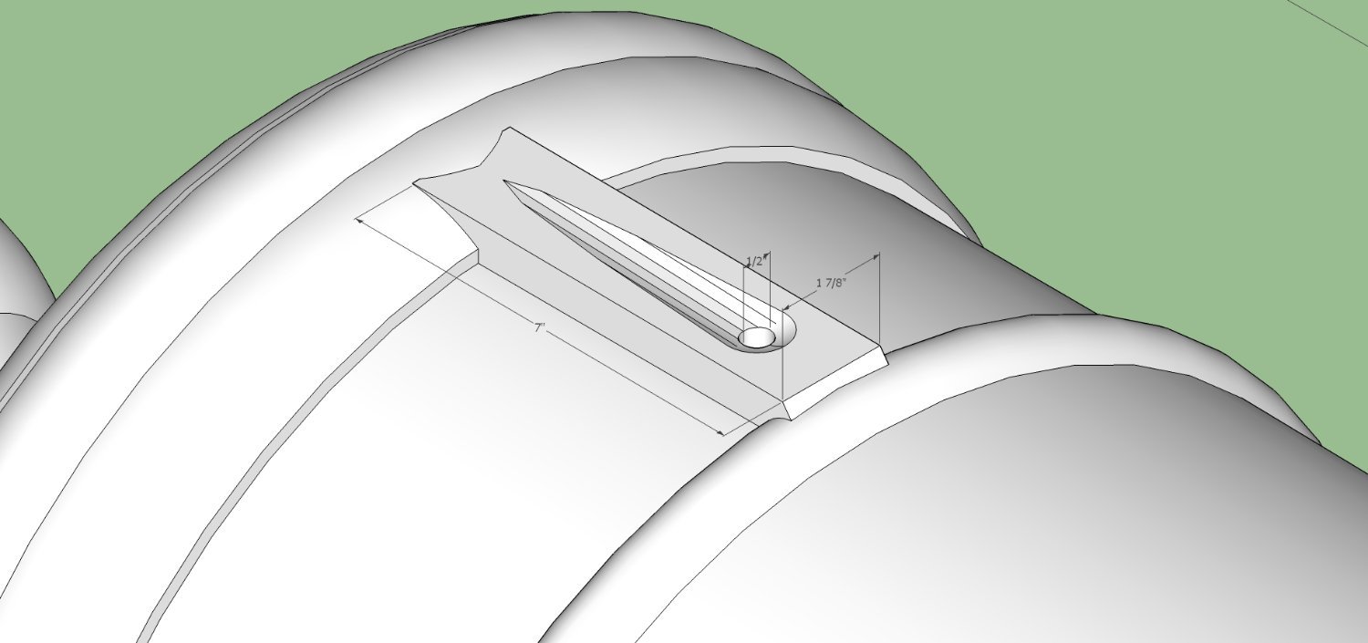
It is 1/2" in diameter, for the 24 pounder. -
6-pounder, Royal Navy cannon barrel - George III era
thibaultron replied to Gabek's topic in 3D-Printing and Laser-Cutting.
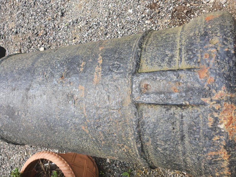
Here is a SketchUp drawing of the flash pan for the long 24 pounder. Feel free to use it for your 6 pounder. Scaling will be needed, but the general layout is the same. I've included a graphic of the drawing, and a picture of an actual cannon. Flash Pan_003.zip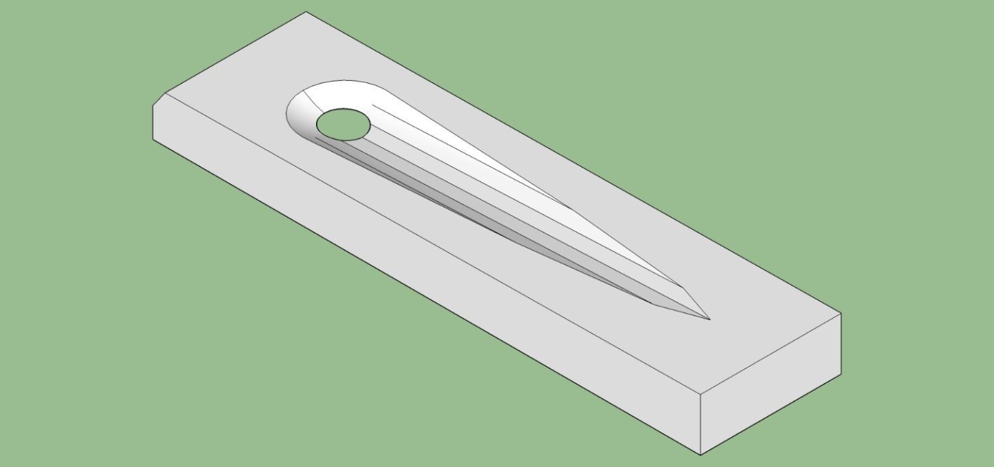
-
6-pounder, Royal Navy cannon barrel - George III era
thibaultron replied to Gabek's topic in 3D-Printing and Laser-Cutting.
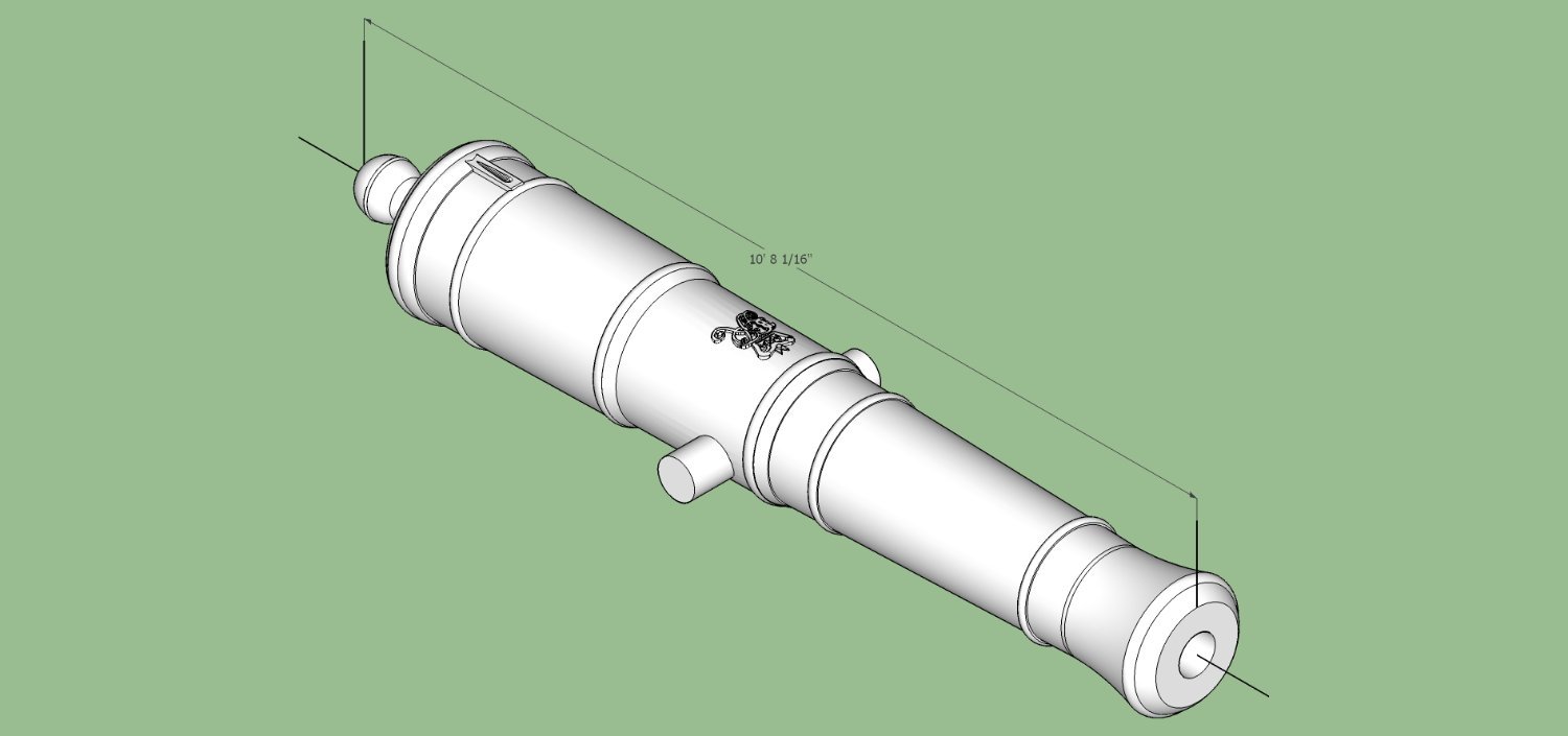
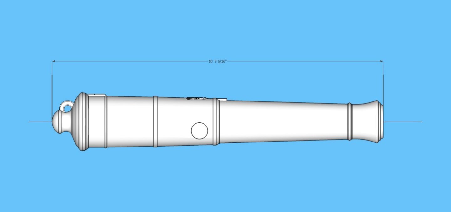
Update long 24 pounder STL. This is scaled to full size 3262.31mm. You can scale that to whatever scale you need. I messed up with the first file, by not scaling it properly. My cat escaped and while chasing her, I forgot where I was in a program, and messed it up. This file has been scaled and error checked using Netfabb. Armstrong Fredricks 24 Pounder Long 3262_31mm.stl -
6-pounder, Royal Navy cannon barrel - George III era
thibaultron replied to Gabek's topic in 3D-Printing and Laser-Cutting.
I'm working on a full set of the Fredricks, as well as several other types, in conjunction with Allanyed. I have the long 24 pounder finished for his carriage project. If anyone needs the short one right away, I could generate that one. Otherwise I will finish the Fredrick set after the Blomefields. This is a graphic of the file Here is the STL Armstrong Fredricks 24 Pounder Long 3253_13mm.stl I wrote a thread about setting up for printing cannons in 3D, to help those who wish to try it for themselves.
-
And then the Bar Fight started! Great build! I'm following along!
-
I drew up a comparison of the barrel to the carriage, and the drawing is correct. First the drawing with a rough line parallel to the barrel, and center lines on the top view of the carriage. Then I transposed the barrel lines onto the top view. So while the carriage looks overly angular, it is an optical illusion. the angle is correct.

-
6-pounder, Royal Navy cannon barrel - George III era
thibaultron replied to Gabek's topic in 3D-Printing and Laser-Cutting.
Not a wasted effort at all! Good job! -
The drawings for Blomefields should be done by mid Sept.. I'm not sure I will finish them before a planed trip.
-
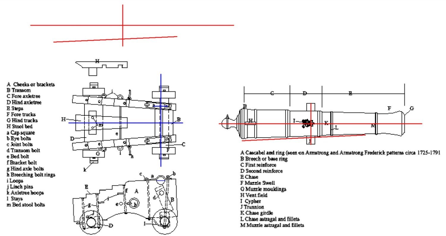
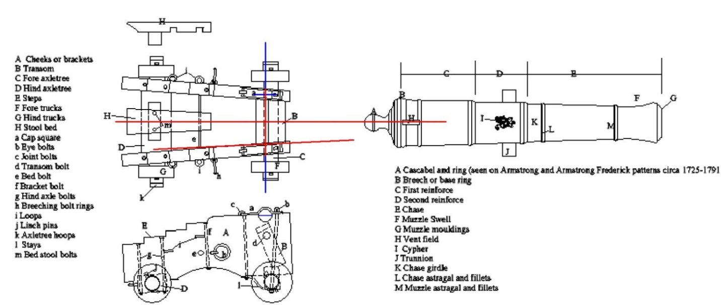
I've been drawing up the Armstrongs and Fredericks. Drawings and photos show them without the rings. The Blomefields I'm working on now do have the rings.
-
The printing of the design on a red painted sail will not work at home. No home printer can print white. I relies on the paper, or decal film being white. There used to be a printer that could do this, it used print ribbons with white being one of the ribbon colors. It has been a couple of decades, though, since they made the ribbons, so that option has gone away.
-
My guess is that the crossbeam is rabbeted in the area of the strap, to allow it the curve around the axle, and rectangular the rest of its length.
-
If you don't already have it, pick up a copy of "How to run a Lathe" by Southbend Lathe company. Grizzly and Amazon carry it. It was written in the 30s, but is a great reference for manual lathe operation.
-
Due to family obligations, I have not gotten any further in my modeling. Physical projects at least, I have been doing a few CADing projects.
-
There should have been a roll of plans showing each assembled frame in scale. I scanned each frame and used the prints of each as a pattern when assembling them.
-
I was thinking more along the lines of using a 4 jaw chuck. setting the screw ends against the chuck face, to index the nut so the top machined surface would be facing out. Tightening the jaws, then machining the top surface. You could loosen two jaws, check the fit, and then return the nut to the chuck, without losing the setup. You would have to remove the screw, between checks and reinstall it. If the jaws are too tall, make up a spacer to fit firmly between the chuck face and the screw. If milling the part, use parallels under the two ends of the screws.