Capt.Bob
-
Posts
69 -
Joined
-
Last visited
Content Type
Profiles
Forums
Gallery
Events
Everything posted by Capt.Bob
-
While battened down on a rainy/snowy afternoon, found 49 minutes of great clippers on YouTube. Enjoy -
- 3,596 replies
-
- 5
-

-
- young america
- clipper
- (and 1 more)
-
Hi All, Sorry Ed, but its too exciting to keep to myself. Vol II is finally available at SeaWatch Books. Guess what just arrived at my door. Yes!, its true there is a Young America Vol II. It has all the appearance of a Master Class in model manufacture. If you never build Young America, the detailed descriptions of how Ed made all those marvelous deck fittings is well worth the price. The techniques are extremely well documented in numerous photos and clearly written text. I can't wait to dig into all the details. Ed, I can't thank you enough for all the hard work that obviously went into the publication. This is just the encouragement I need to get back to work in the shop.
- 3,596 replies
-
- 7
-
-
- young america
- clipper
- (and 1 more)
-
Hi All, Sorry Ed, but its too exciting to keep to myself. Vol II is finally available at SeaWatch Books. https://www.seawatchbooks.com/ Just ordered mine.
- 3,596 replies
-
- 5
-
-
- young america
- clipper
- (and 1 more)
-
Ed, That was what I assumed, but just wanted to make sure. Don't like mistakes at this stage. I couldn't imagine anchoring a mast step on the 4" planking. Drainage was my other question. Like the dust case. My biggest case is 42' X 32" X 15" and seems huge. It must be like having an elephant in the shop. Thanks, Bob
- 3,596 replies
-
- 3
-
-
- young america
- clipper
- (and 1 more)
-
Ed, Confused (again) Page 108 Left hand col, last sentence "...limber channel is 10" Mast Steps drawing: Side chocks 48" x 16" height to top of the keelson. The side chocks sit on the frames inside the limber channel. Can't get a 16" chock inside a 10" channel. Which is correct?? Or do I leave a 6" x 48" space in the common planking at the mast step? Bob
- 3,596 replies
-
- 3
-
-
- young america
- clipper
- (and 1 more)
-
Ed, Got it. Made several concentrations in an attempt to find a workable minimum. Somewhere between 40 & 50:1 got the job done and left no residual staining. Moving on to the common planking.
- 3,596 replies
-
- 4
-
-
- young america
- clipper
- (and 1 more)
-
Ed, How do you blacken copper wire ends with LoS without staining the wood? I'm finishing up the bilge ceiling.
- 3,596 replies
-
- 4
-
-
- young america
- clipper
- (and 1 more)
-
Ed, Its now 5:30AM and I'm up worrying. I checked the cross section view at sta 25 and recognized the thickness of the rail. My measurements were al little off. 6" makes everything come out right. I'm going back to bed!! Bob
- 3,596 replies
-
- 5
-
-
- young america
- clipper
- (and 1 more)
-
Ed, Thanks for the explanation. I still have some confusion. The height at Sta 28 from the keel to the "Top of Wale" & "Red Line" on dqgs 4 & 5 respectively in the same. On dwg 4 from the Wale to the planksheer is 30", but on dwg 5 the planksheer is only 23". What am I missing?? I couldn't find any 24 awg wire in my vast pile of stuff, so while ordering some other things I ordered a roll. I didn't realize it at the time, but its a roll of just over 800' of wire. That should be enough. Also, I have never been pleased with epoxy bonds to metal, especially quick curing ones. Its hard to keep wire really clean when constantly handling small pieces. This new roll has a .001" plastic coating of some sort and it seems to bond well. I did some pull test with the coated and bear wire. The bare wire bond failed adhesively, but the coated wire failed cohesively. I have some West One epoxy left over from the days when my garage was a boat shop. It has a 12 hour cure time and if I spread a small puddle on a piece of wax paper I can extend the working time to over an hour. I've started pining the main deck clamp. I hope everything is in the right place. Its 2:30AM, time to quite. Thanks for all the help, Bob
- 3,596 replies
-
- 4
-
-
- young america
- clipper
- (and 1 more)
-
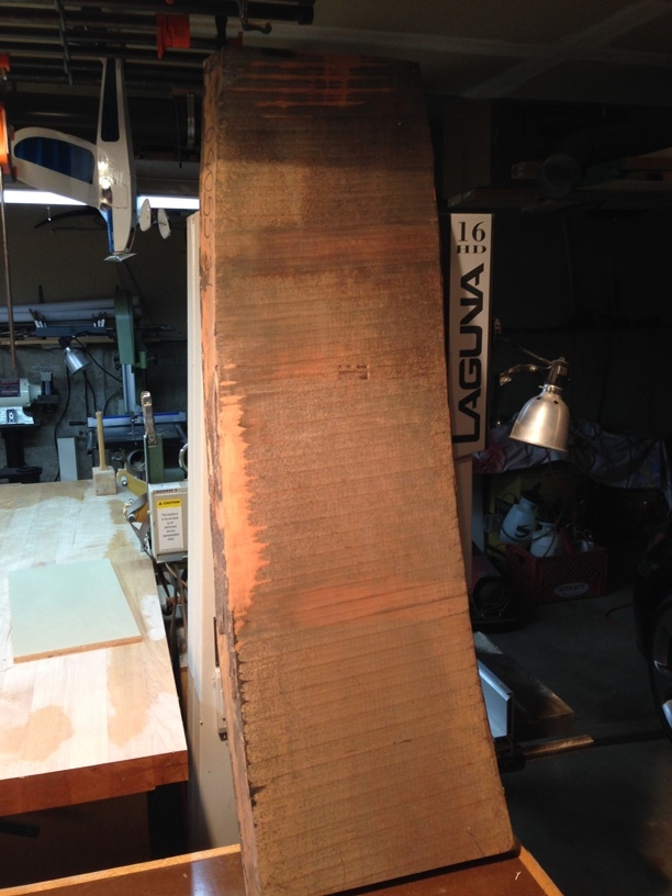
Thank you all for your kind remarks. Roger: It is a neat trick for quick results. I have used it on occasion in the past with softer woods like balsa. Rather than boiling water, I would tightly wrap the pieces in a paper towel saturated with water. The towel provided a sufficient supply of moisture and enough pressure to help force steam into the material. Hard woods may not be quite as easy. I can tell you that without sufficient moisture you can set the piece on fire. I'd rather not explain how I know this. I ran several build threads on RC Universe while building large RC airplanes. I would build one project a year, which usually took 6-8 months. Progress on airplanes can be quite dramatic and very conducive to photo essays rather than dialogue. The YA project, at least for me, is a very long term affair. I have no illusions about ever completing it. I not sure that I have enough years left. However, it has become one of the most rewarding projects I have ever attempted. It is truly the journey and not the destination that is of the most value. In the meantime I have my books, music, woodshop, and time spent in the country club bar with friends lying about my golf game. Honestly, I couldn't be happier than to sit and the feet of the Master and enjoy the beauty of his work. With Ed's indulgence I will be happy to inject a brief update now and then. For the Master: After resolving approximately 150 data points I have come to the conclusion that the correct dimension between the top surface of the three deck clamps is 84". Please confirm. I have attributed any significant data variation to print distortion and measurement error. As a means of eliminating as much error as possible I am designing a jig to set the middle and lower deck clamps using the main deck clamp as a datum. These feature are so fundamental that it deserves extra effort. I'm a little surprised that I appear to be the only one enjoying the build of such a great vessel. Also, what man can pass up an excuse to buy more tools. Just for prospective I've attached a photo of where the ship was born. 12 bdf of 8/4 Swiss pear. Later, Bob

- 3,596 replies
-
- 6
-
-
- young america
- clipper
- (and 1 more)
-
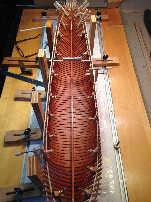
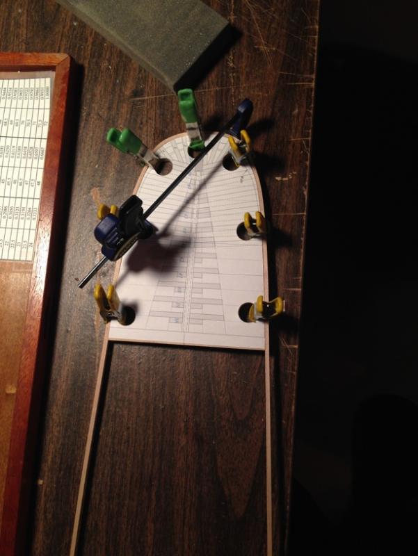
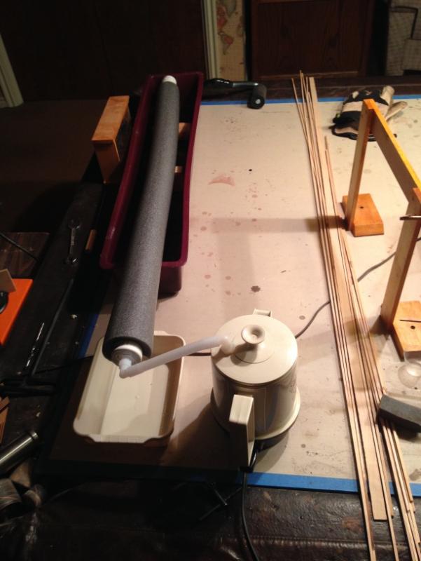
While there is a lull in the action, I thought I'd share some progress on my YA. After making frames for what seemed like forever, its finally time to begin on the ship's interior. Ed suggested starting with the bilge ceiling, but since it required removing the shell from the shipway (which I have never had the courage to do), I've decided to start with the deck clamps. With the three deck clamps in place the structure will be far more rigid and less prone to warping. Given the importance of these initial structures I have had nightmares about alinement accuracy. I keep re-measuring everything constantly. The deeper I get into this project the greater the investment. It can get a bit scary. Looking ahead at the bending members I decided a small steam box is going to be essential. I built this small one from an old electric kettle, tubing, and PVC pipe. I made a 12", 18", & 36" insulated tube oven to accommodate different sizes. I steamed an 8 X 8 piece of hard maple and bent it around the stern rail pattern. It seemed to work quite well. However, PVC doesn't like elevated temperatures. I'm going to try ABS. I do have a question for Ed. You used 24 awg wire and 5 minute epoxy to secure the deck clamps, et al. Also, you peened the ends of the wire after cure. I'm concerned that 5 minute epoxy has too short a working life and would constantly mixing small batches. Additionally, by peening the ends after trimming I would be concerned about breaking the epoxy/copper bond. Any advice? Its time to charge into the breach. ....., the brave die but once. Bob

- 3,596 replies
-
- 14
-
-
- young america
- clipper
- (and 1 more)
-
Hi Ed, There appears to be a discrepancy between the spanker mast bracket show in the third photo and the drawing. You have added a flange on the forward face of the bracket which does not appear on the drawing. Am I mistaken? Bob
- 3,596 replies
-
- 1
-
-
- young america
- clipper
- (and 1 more)
-
Seriously guys, does anyone keep their shop that clean?? Very nice full view. I was going to ask you about the wax finish and bonding. I have been using a 1/2 lb cut of Tiger Flake shellac on the fore/aft surfaces of the timbers prior to installation. A single coat seals the grain without build up. Do you have any idea when Vol. II will be available? I'm ready to send my check. Bpb
- 3,596 replies
-
- 2
-
-
- young america
- clipper
- (and 1 more)
-
captharv2, Thanks for the Spar Shop link. Very impressive. Spent some time in Grey's shipping rocket motors to Japan in the 90s. Beautiful harbor, I even considered it for retirement, but a little too damp. Rob, I should read a little more carefully before opening my mouth (it was late). "Rounding" a segmented mast without banding or assembly must have been a real trick. Shipwrights were amazing craftsmen. Your simulation looks great.
- 3,596 replies
-
- 5
-
-
- young america
- clipper
- (and 1 more)
-
Turned?? Masts and spares weren't turned. Try to imagine a lathe big enough to do it and powered by what? They were fashioned as Ed described. I made a 16' mast for my sailboat by hand, its really quite easy. Bob
- 3,596 replies
-
- 2
-
-
- young america
- clipper
- (and 1 more)
-
W2YSM, Yes, it will take a little while to soften. There are "debond" solutions available from CA suppliers. Try Tower Hobbies.com Bob
- 3,596 replies
-
- 2
-
-
- young america
- clipper
- (and 1 more)
-
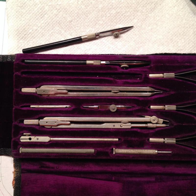
Concerning the application of CA in very small quantities, I use the ink pen from an old drafting set. For those of you who aren't old enough to remember, imagine making ink drawing by hand. I have some drawings that my grandfather made in 1898 while in tech school. The ink pen is infinitely adjustable and allows you to control the gap and provide extremely small applications of either thin or medium CA. It doesn't work very well for thick CA. Roger, they do make a vapor free CA that eliminates the nose/throat problem. It acts more slowly and avoids the flash cure and associated vapors. Bob
- 3,596 replies
-
- 14
-
-
- young america
- clipper
- (and 1 more)
-
Ed, A couple of questions: The wooden stock appears to be laminated. Presumably this was done for strength and to simplify the mortise fabrication? Also, you imply that the wood stock bands were blackened after installation. How did you keep the wood stock from discoloration? In the photo the blackened brass appears to be more bronze colored than black. Is that an artifact of the photography or the accurate color? Bob
- 3,596 replies
-
- 3
-
-
- young america
- clipper
- (and 1 more)
-
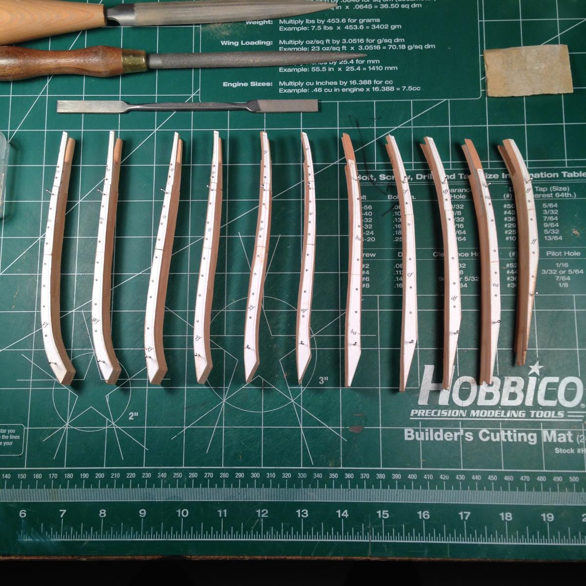
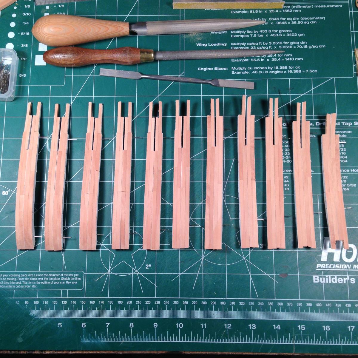
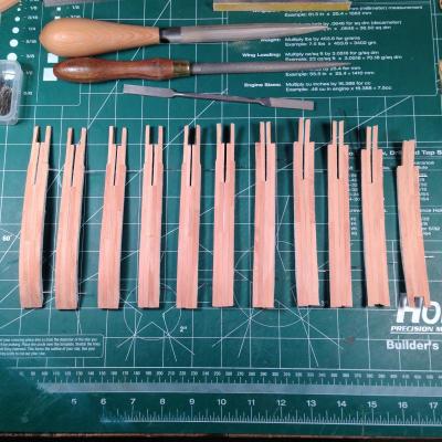
Hi Ed, While you're out doing spring cleanup, I thought I'd pass along my appreciation of your pin alignment system. I'm just finishing up the forward half & cant frames. After hand finishing them individually, I decided to double check each as a matched pair. I've gotten much better at sanding to the profile lines, but didn't want to risk a mismatch between port & strb. The pin holes are 0.024" and I used 0,026" pins for a nice tight fit. I am very pleased with the results. Each frame pair fits perfectly without further finishing. I am really impressed with the capability of your alignment system. It even makes old guys like me look good. Setup and installation is going to be my next hurdle. Always look forward to your next post. Now I have to get after my spring yard work. Bob

- 3,596 replies
-
- 20
-
-
- young america
- clipper
- (and 1 more)
-
Ed, Page 61: Figure 3-39 Should be: Figure 5-39 Pattern 29a: The 3rd futtock is sided as 10". Is this accurate? Everything else is sided as 11" Bob
-
Ed, Thanks for the confirmation. I've got too much invested to screw things up now. Also, the background information is always interesting. Bob
-
Hi Ed, Your PM account is full. I left you a note on the book forum. Bob
- 3,596 replies
-
- 4
-
-
- young america
- clipper
- (and 1 more)
-
Ed, I'm getting ready to reside the futtocks on A thru U and ran into a curiosity. On frame Ua the siding of the lower futtocks is marked 12" instead of 14" and labeled "Lower Futtock" instead of "1st Futtock". Also, the 3rd and 5th futtocks are marked 10" and 9" respectively as opposes to 12" and 10". This makes Ua unique. Are the siding references accurate? Bob