ppddry
-
Posts
42 -
Joined
-
Last visited
1 Follower

Recent Profile Visitors


-
 JerryTodd reacted to a post in a topic:
HMS Pandora 1779 in 3D
JerryTodd reacted to a post in a topic:
HMS Pandora 1779 in 3D
-
JerryTodd reacted to a post in a topic:
HMS Pandora 1779 in 3D
-
JerryTodd reacted to a post in a topic:
HMS Pandora 1779 in 3D
-
JerryTodd reacted to a post in a topic:
HMS Pandora 1779 in 3D
-
JerryTodd reacted to a post in a topic:
HMS Pandora 1779 in 3D
-
JerryTodd reacted to a post in a topic:
HMS Pandora 1779 in 3D
-
JerryTodd reacted to a post in a topic:
HMS Pandora 1779 in 3D
-
JerryTodd reacted to a post in a topic:
HMS Pandora 1779 in 3D
-
JerryTodd reacted to a post in a topic:
HMS Pandora 1779 in 3D
-
JerryTodd reacted to a post in a topic:
HMS Pandora 1779 in 3D
-
HMS Pandora 1779 in 3D
ppddry replied to ppddry's topic in CAD and 3D Modelling/Drafting Plans with Software
Hi Mark, That's a good point! I think I will dig deeper on this. Thank you for pointing it out. There is another inaccuracy you may notice is that the gammoning loops are not arranged correctly. I tried to draw them in the correct way but the results always look awkward. So I drew them as they are now. Best regards, Jingyang -
HMS Pandora 1779 in 3D
ppddry replied to ppddry's topic in CAD and 3D Modelling/Drafting Plans with Software
Hi Mark, Thank you very much for your explanation! I deliberated on this very issue during the build. I read Ed Tosti and David Antscherl's books and was aware of that they shew different configurations for the knee of the head. But since they are of different classes of ships and I did not have the contemporary plans showing the construction of the knee of the head of the Porcupine class of ships, I decided to just follow the plans in the Anatomy of the Ship book. I think I will have to do more research into the contemporary sources before I can further revise this part. As for the rounding at the front of the knee of the head, I have been trying to maximize it while keeping the width at the top of the timber marked as 5 in plan B2/2 in the AOS book the same as the width of the front face of the timber marked as 1 in the same plan. Best regards, Jingyang -
HMS Pandora 1779 in 3D
ppddry replied to ppddry's topic in CAD and 3D Modelling/Drafting Plans with Software
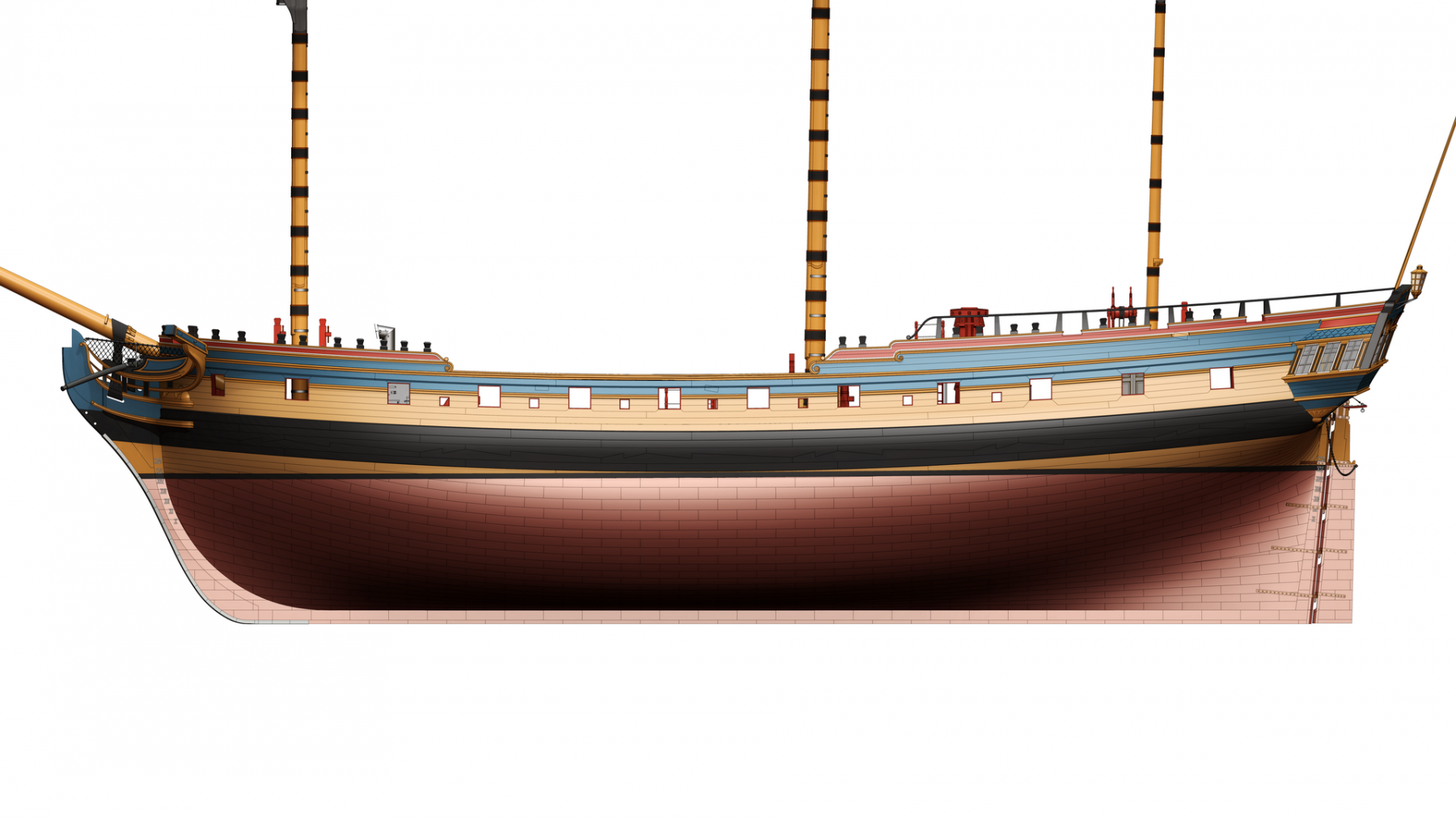
Hi Mark, Thank you very much to pointing out the inaccuracy! The following picture shows the standard as of now. It seems that I need to modify it further. Also, do you mean the two light blue edges should be rounded near the stem post but remain sharp near their front end? Best regards, Jingyang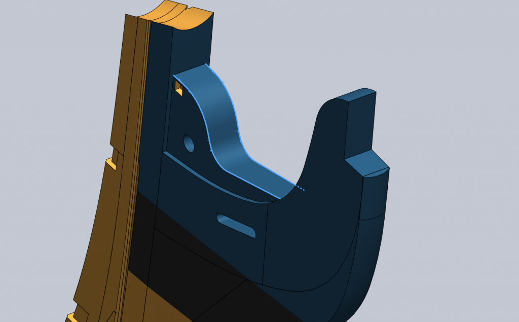
-
HMS Pandora 1779 in 3D
ppddry replied to ppddry's topic in CAD and 3D Modelling/Drafting Plans with Software
Hi Tim, will the following pictures be of any help?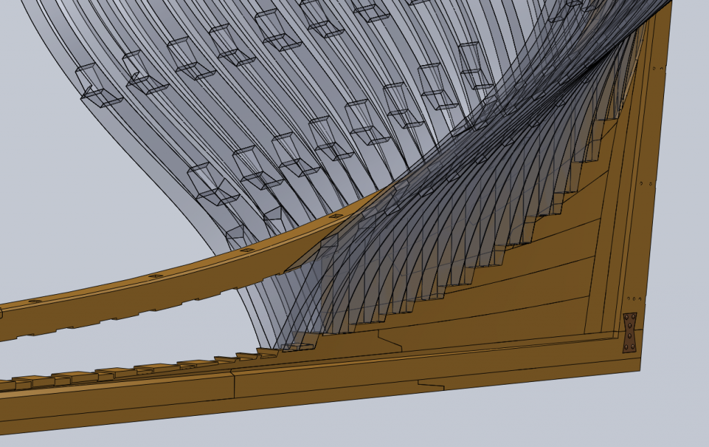
-
HMS Pandora 1779 in 3D
ppddry replied to ppddry's topic in CAD and 3D Modelling/Drafting Plans with Software
Hi Experiment, Yes, it is done from the cross sections in the book, corrected with the scantlings of the frames listed in The Shipbuilder's Repository. I just sent an reply to your PM. Best regards, Jingyang -
HMS Pandora 1779 in 3D
ppddry replied to ppddry's topic in CAD and 3D Modelling/Drafting Plans with Software
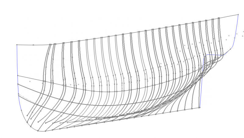
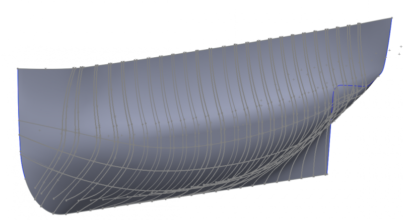
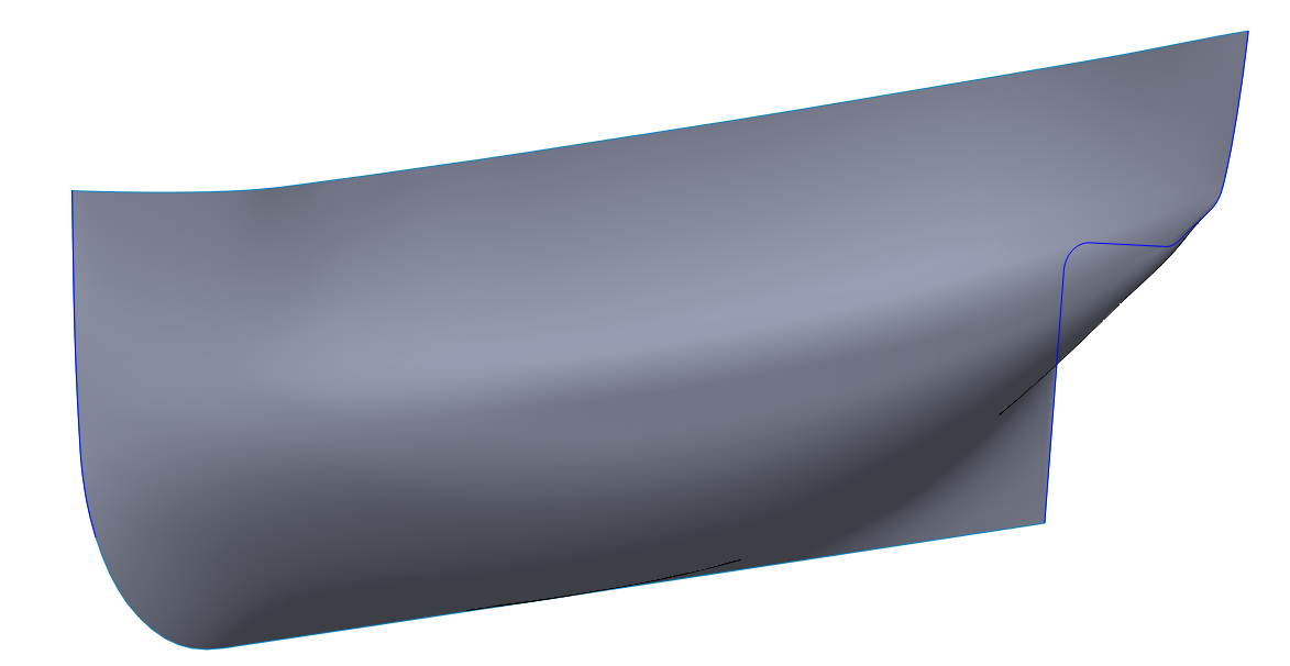
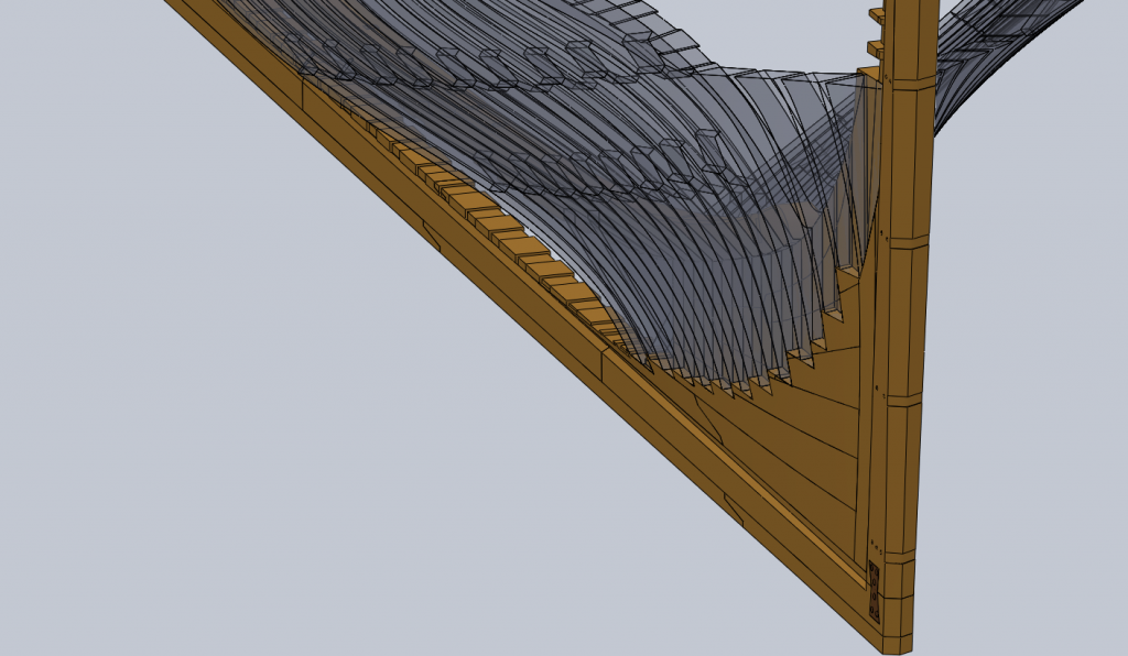
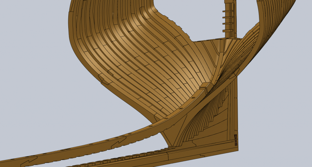
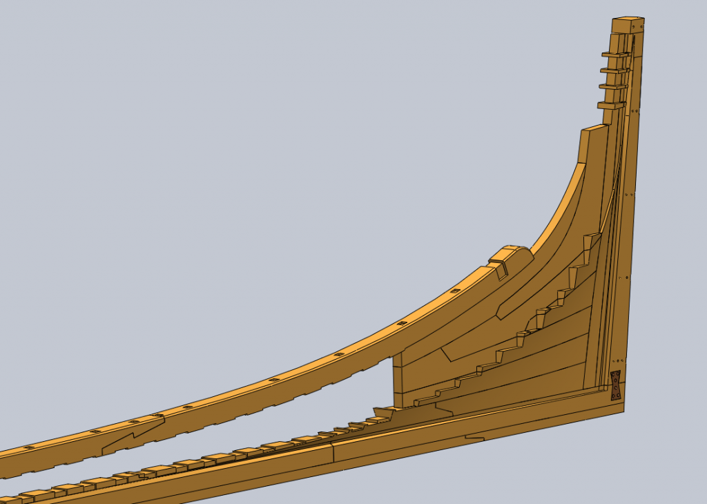
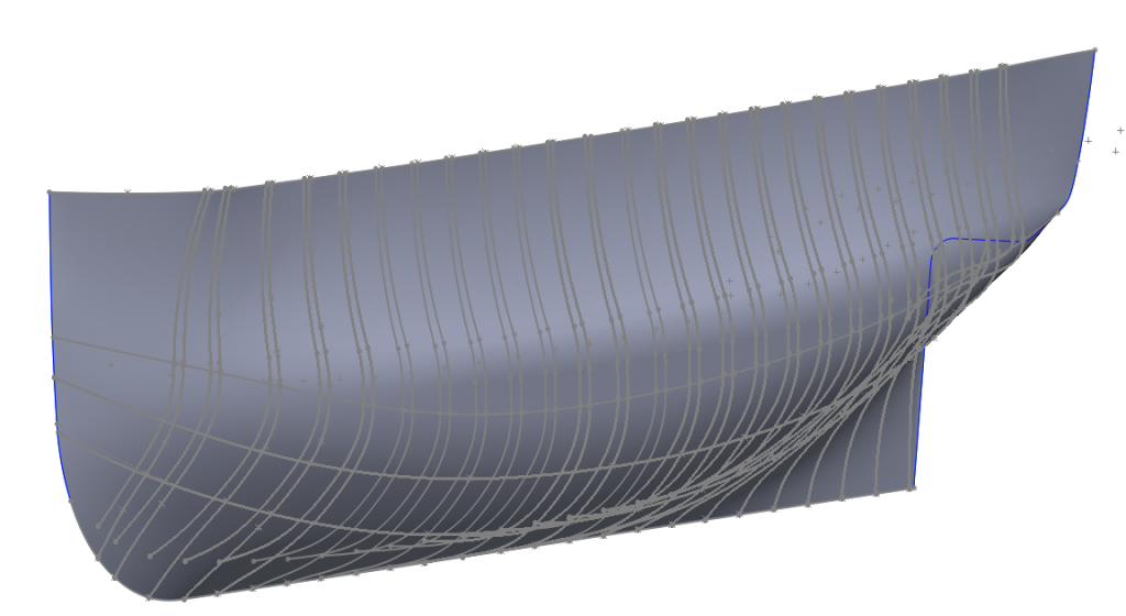
Hi Daniel, Sorry for the VERY late reply . The process is as follows: firstly the 2D drawings of the frames are imported on to different reference plans in Solidworks, then draw the boundary of the hull surface with the help of other imported 2D drawing curves, finally use the boundary surface feature in Solidworks to construct the hull surface guided by the curves. As can be seem from the pictures below. And Yes, a set of 2D drawings can be generated from the 3D model. Best regards, Jingyang

-
ppddry reacted to a post in a topic:
HMS Pandora 1779 in 3D
-
ppddry reacted to a post in a topic:
HMS Pandora 1779 in 3D
-
HMS Pandora 1779 in 3D
ppddry replied to ppddry's topic in CAD and 3D Modelling/Drafting Plans with Software
Hi Garward! It is a gorgeous model! If I recall correctly this is one of the models that inspired me into undertaking this project -
HMS Pandora 1779 in 3D
ppddry replied to ppddry's topic in CAD and 3D Modelling/Drafting Plans with Software
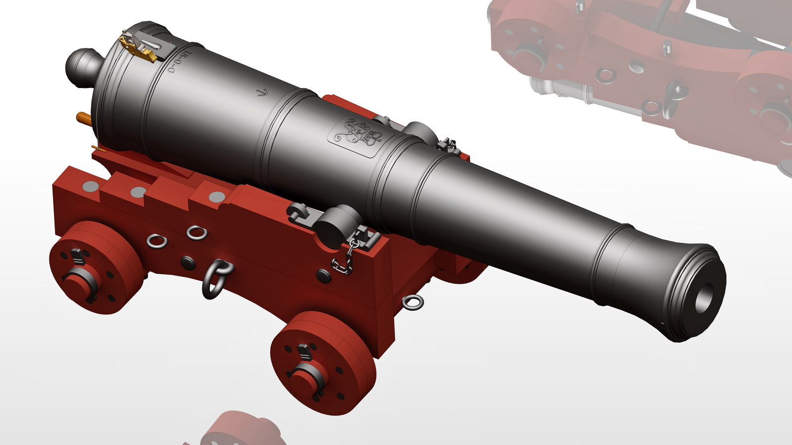
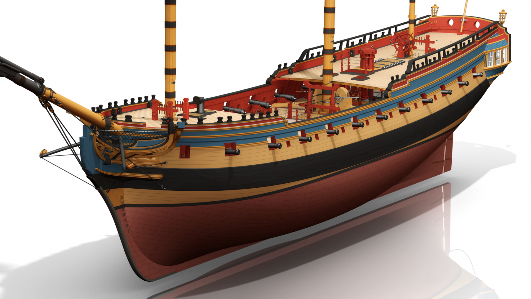
Here are two pictures of a 6-pr gun.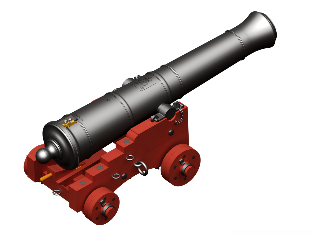

- 106 replies
-
- 13
-
-
HMS Pandora 1779 in 3D
ppddry replied to ppddry's topic in CAD and 3D Modelling/Drafting Plans with Software
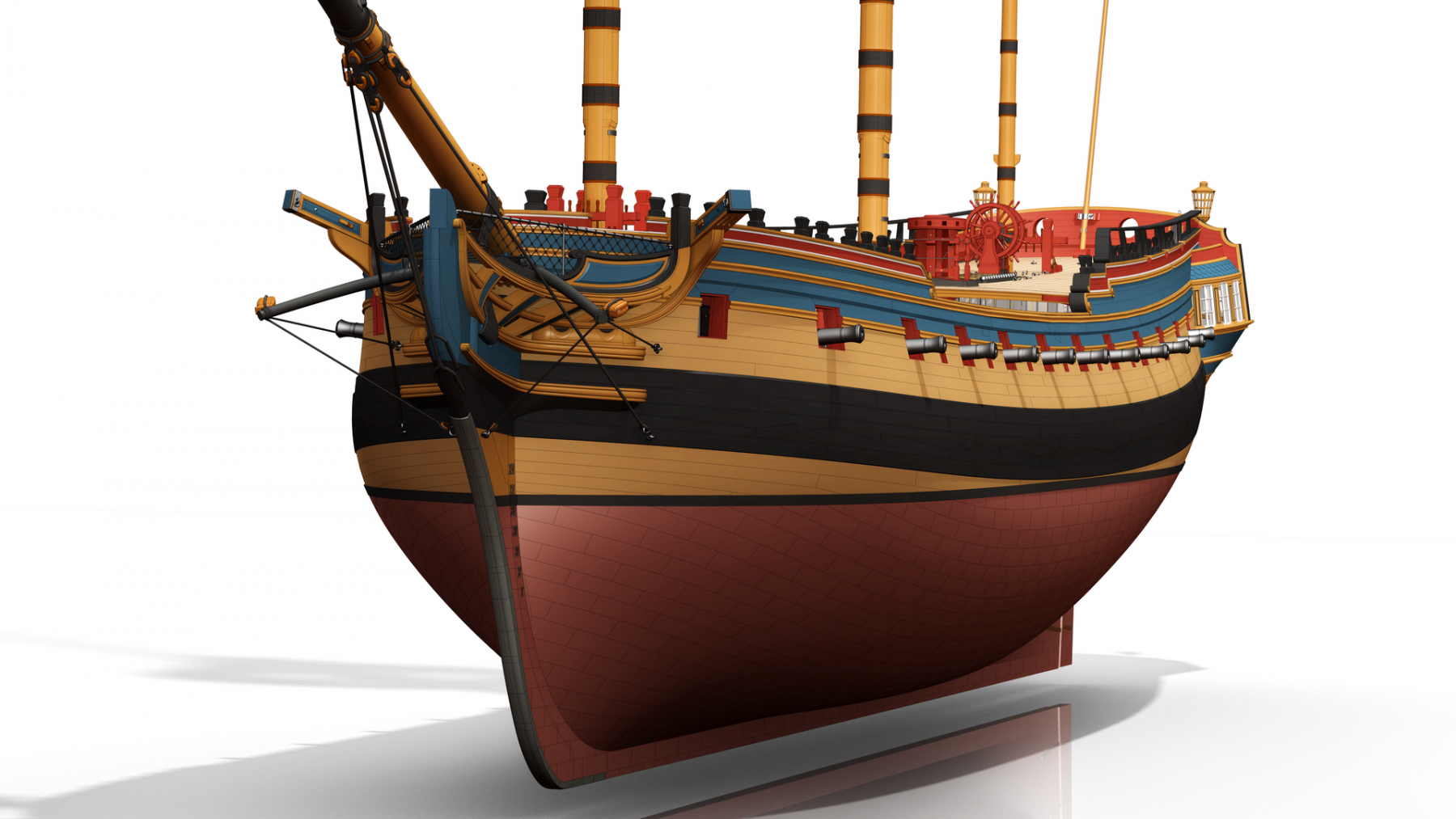
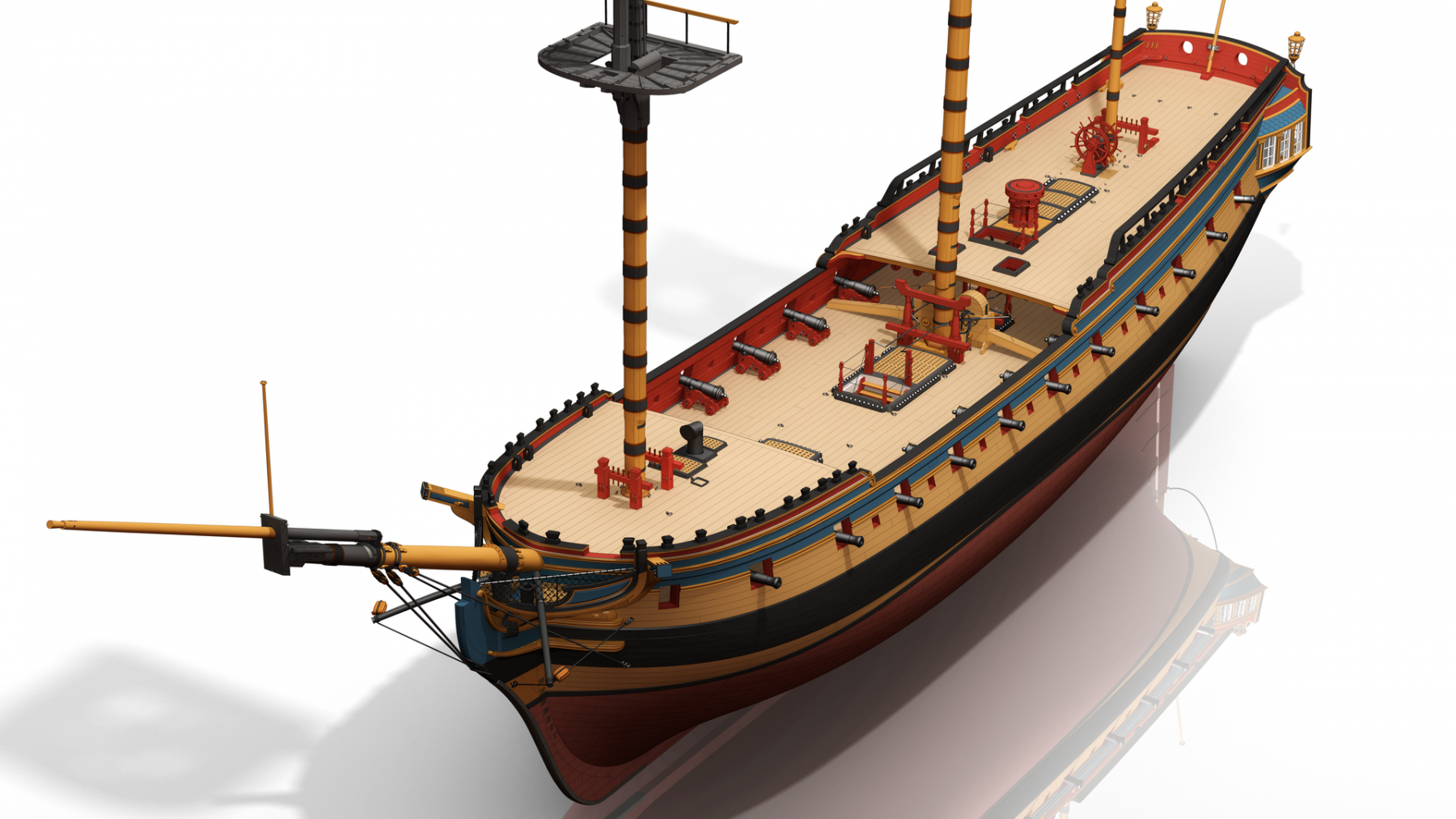
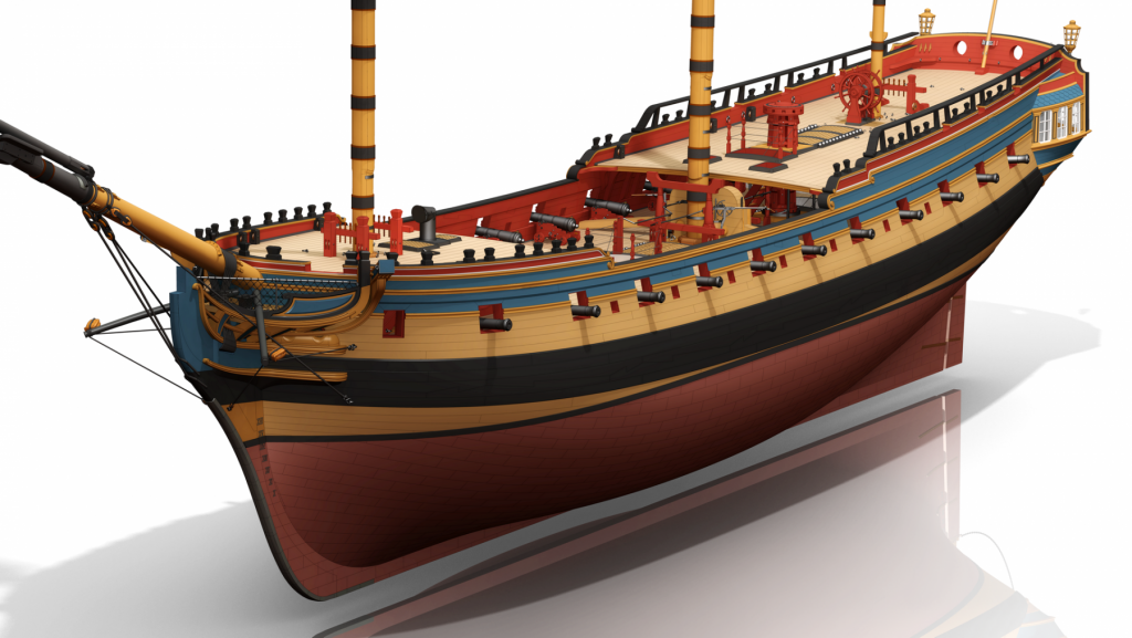
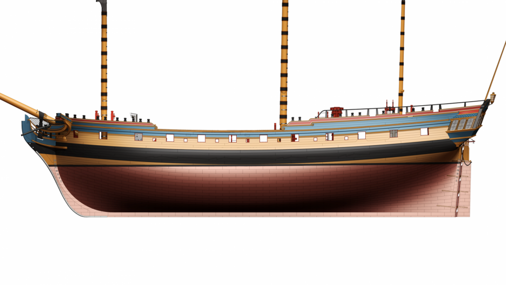
It has been a long time since the last time I visited this website, check the messages (I am very sorry that I did not check them and reply earlier), or updated the model. A lot of things happened over these years, and I had much less time to indulge myself in my hobby than before. I made small progress on the model over the years, but still far from completion. As can be seem from the attached pictures, the beakhead and bowsprit are completed, with their standing rigging in place. The 6-pr guns are also placed at their ports.

- 106 replies
-
- 10
-
-
HMS Pandora 1779 in 3D
ppddry replied to ppddry's topic in CAD and 3D Modelling/Drafting Plans with Software
Stefan, your model looks impressive! I am working on the figurehead now, and it is already quite a struggle, not to mention the rigging ... -
HMS Pandora 1779 in 3D
ppddry replied to ppddry's topic in CAD and 3D Modelling/Drafting Plans with Software
Thanks everyone for the good words! Garward, thank you for providing more details about the Pandora model. That’s the very model that inspired me into doing this 3d build. Bernard, that’s a great video! I have seen it before, but I still couldn’t help but watched the full 10 minutes of it again. Tony, it’s alright. My progress is slow so it is good to have something else to fill in the gap. -
HMS Pandora 1779 in 3D
ppddry replied to ppddry's topic in CAD and 3D Modelling/Drafting Plans with Software
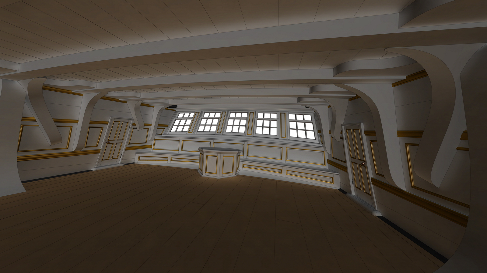
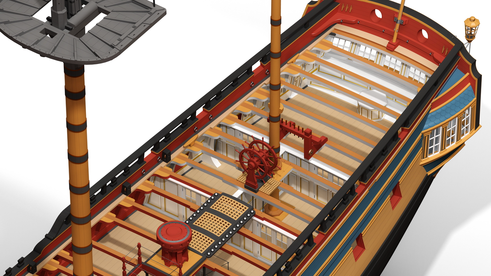
Gaetan, this is for you. Inside the great cabin, looking aft.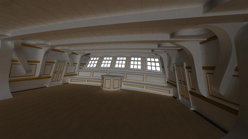
- 106 replies
-
- 12
-
-
HMS Pandora 1779 in 3D
ppddry replied to ppddry's topic in CAD and 3D Modelling/Drafting Plans with Software
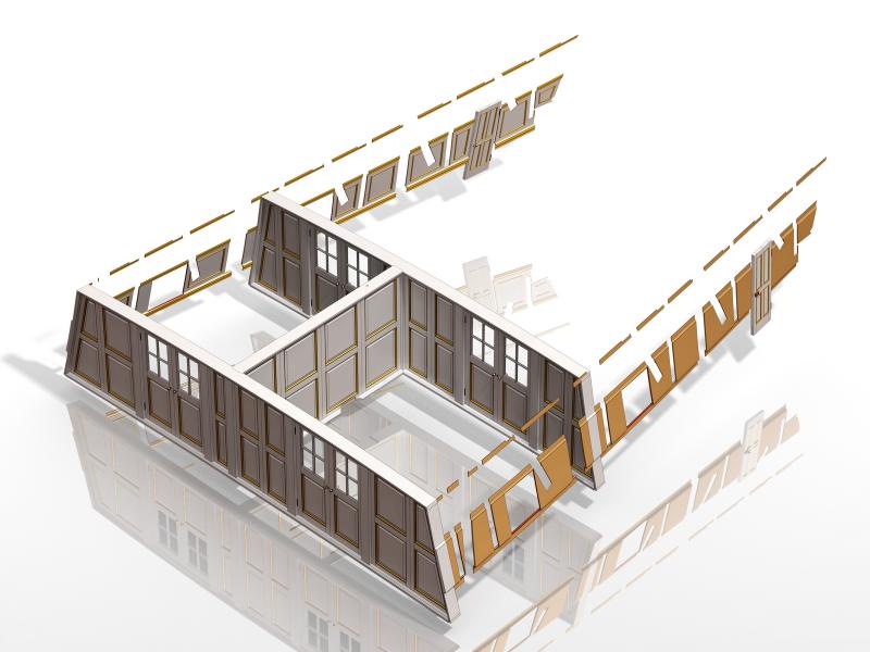
2013-03-18 Upper deck bulkheads finished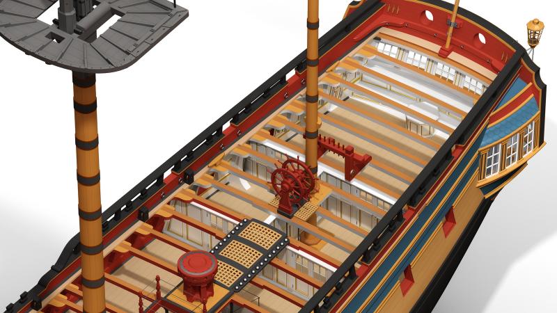
- 106 replies
-
- 12
-
-
HMS Pandora 1779 in 3D
ppddry replied to ppddry's topic in CAD and 3D Modelling/Drafting Plans with Software
Thank you, Mark, Tony, and Gaetan. Gaetan, it is indeed much easier to visualize the parts in 3D and it helps to resolve some contradictions between different 2D drawings. I am still working on the model, but slowly. I will try to render a picture showing as if someone is inside soon. -
Hi Tony, Does the software you are using have any surfacing commands like "lofting" or "boundary surface"? Such commands should do the job. The following figures show the process of using the "boundary surface" command in Solidworks to generate the hull form from a set of station lines and some other assisting curves.