Thistle17
-
Posts
1,042 -
Joined
-
Last visited
Content Type
Profiles
Forums
Gallery
Events
Everything posted by Thistle17
-
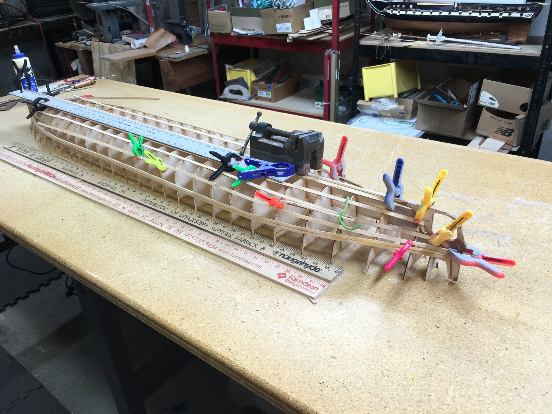
 A re-enforcing comment. My Essex kit is about 28 inches long and has a two part false keel. For a demo I assembled it using an Ed Tosti like gantry jig for this specific purpose. The keel members were flat to begin with. After assembling 20 of the bulkheads one could notice a slight twist to the false keel. This could only be trued by inserting the stiffeners (3/8 X 1/4 beams on each side of the keel) into the precut notches of 19 of the 22 bulkheads. Even multi layer Baltic Birch ply will warp slightly just sitting on a flat surface in my low humidity shop accumulating moisture unevenly (on the top side vs the bottom). Having built a few houses in my time if you do not get the foundation true you will constantly be correcting, and living with the results, all they way to the roof top. Joe
 -
Knowing your work and your expertise it will not be too long before you are pacing alongside the master and his protégé! I on the other hand will be learning from the masters. Happy to have you in the fray. Joe
- 642 replies
-
- 3
-

-
- winchelsea
- syren ship model
- (and 1 more)
-
HMS Winchelsea - Special Offer
Thistle17 replied to kurtvd19's topic in NAUTICAL RESEARCH GUILD - News & Information
Kurt I signed up in March for my usual 1 year membership and just submitted via Pay Pal for the Winne plans just this week. Am I able to take advantage of the offer by extending my 1 year to 2? Joe -
When I get excited (sort of like when I see a pretty woman) I tend to leap off into free space without a parachute. I had forgotten the group build by model subject (as I am so used to heading straight to a topic of interest/area) and logged in under the Scratch Banner. Then upon discovering the Winne Group on my windows 10 system I wasn't able to make an entry (this was when the Group was not yet open). Probably because I was still "free falling". Thank you for moving me over and as you can see all works well now. Joe
-
For some reason the Winne group project doesn't show up when you directly access the Group forum. Can the administrator move me over there please? Joe
-
As we spoke at the NE Conference, this may be my last model build. It is difficult to say that but I have to be realistic about where I am in life. I can't imagine a more elegant subject to tackle. As you requested Chuck, I enter the "waters" and make a commitment to build a Winchelsea of cedar and will want to build it from your modular or mini kit offerings starting with the "starter" installment. Given the human factors a scratch version is not practical for me. Joe
-
There is a "feeding frenzy" about to happen in these waters. Should I keep to the shore and wait a bit or wade in? Joe
- 1,784 replies
-
- 1
-
-
- syren ship model
- winchelsea
- (and 1 more)
-
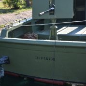
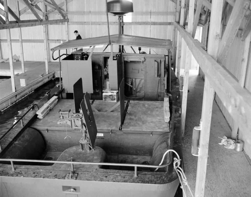
Build development moves on and the hull is beginning to see the addition of more detail. The "rail" earlier cited is proving to be somewhat of a challenge in that the lamination method and the curvature fairing, especially when considering the tapering of the inside curvature to it's desired uniform top dimensions is required. Sections are being made up of the 1/4 inch basswood and dry fitted to the hull. At the moment I am contemplating a build up lamination off the bow (much like a hull frame) and shaping much of it "in hand" so to speak. Pictures of a starboard assembly to follow. While the stern detail is proceeding, without episode, one of our members has begun the aft tripod for the 50 caliber machine gun. We have a decent redrawn and dimensioned picture of the tripod and this is supplemented by one of the archival photos we have in our drop box. However the photo attached does not give sufficient detail in regards to how the gun is mounted to the tripod. If someone out there has a better photo source it would be helpful if you could give us the reference. Posting update 8/11/2019: We are extremely grateful to our colleague on the west coast, Joel L., for supplying excellent archival photos of the gun mount and radios for our model construction. For those interested he has sent an archive reference for study. USN PBR Build Photos.pdf. Included is early build information of the very first PBRs. I am now told that this is a Mark II PBR. Yet I have to believe that the mount save the lower level is of little difference to the Mark I. Joe Mrk I's had a tripod mount
-
Bob thank s for your input. Your input is valued and I stand corrected. I had picked that erroneous information up on another site. It is somewhat ironic that we should receive your input as I was handed a listing of PBRs in either individual or group hands just yesterday. I believe the reference you cite is one in the same source. And this Mare Island reference is one to follow up on. How did that get by us? Again thank you. Joe
-
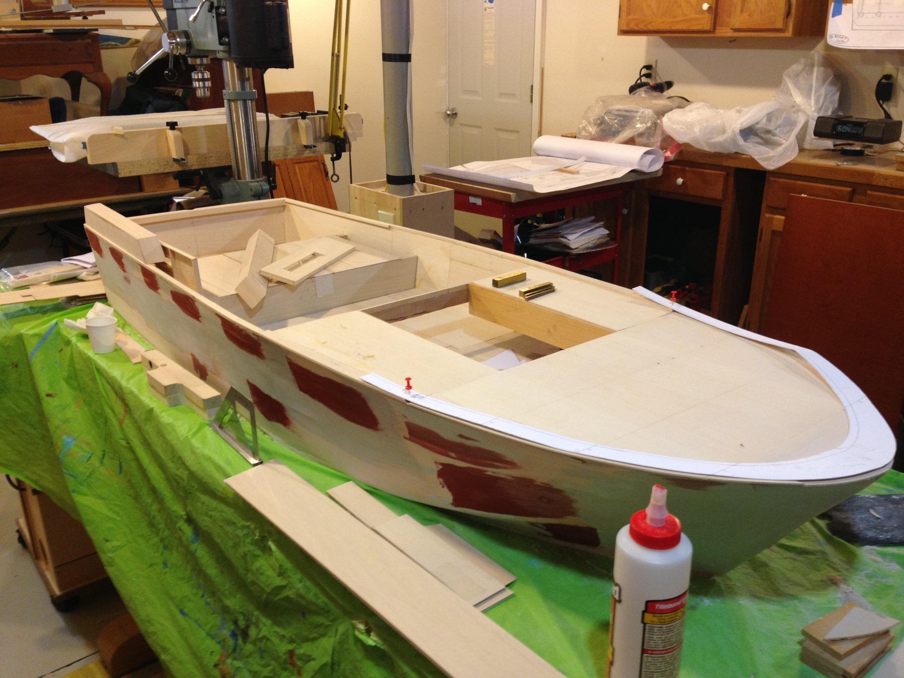
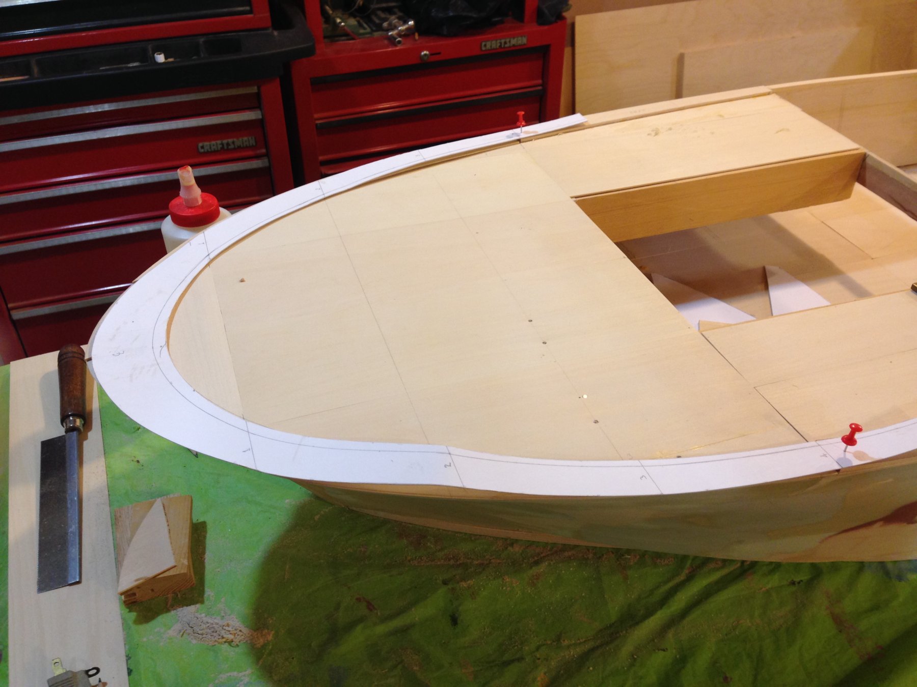
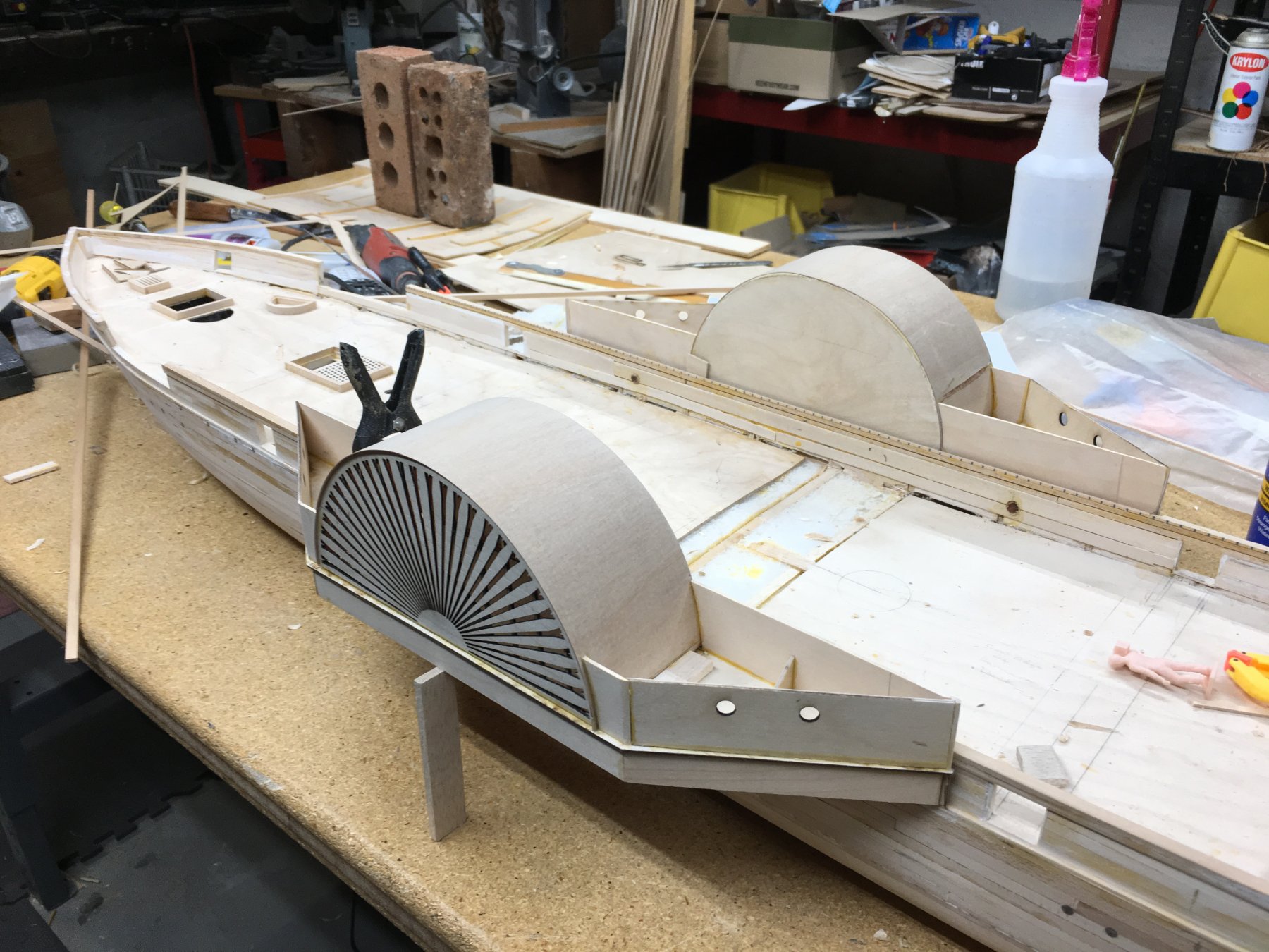
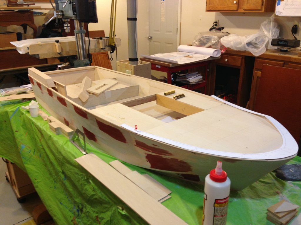
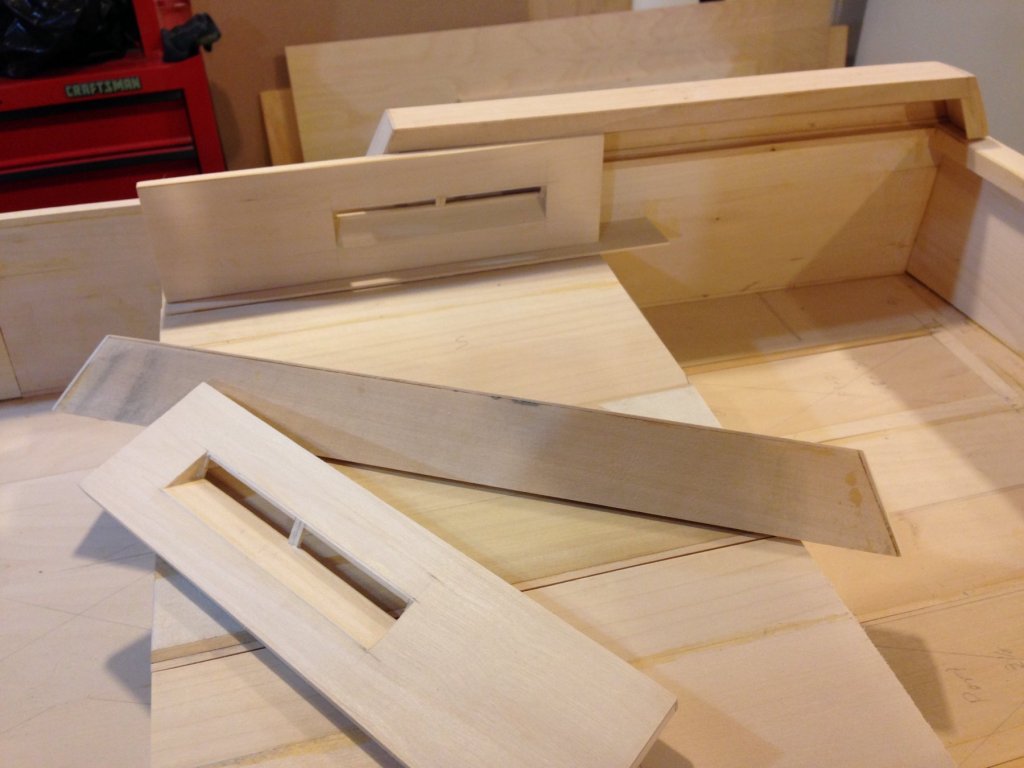
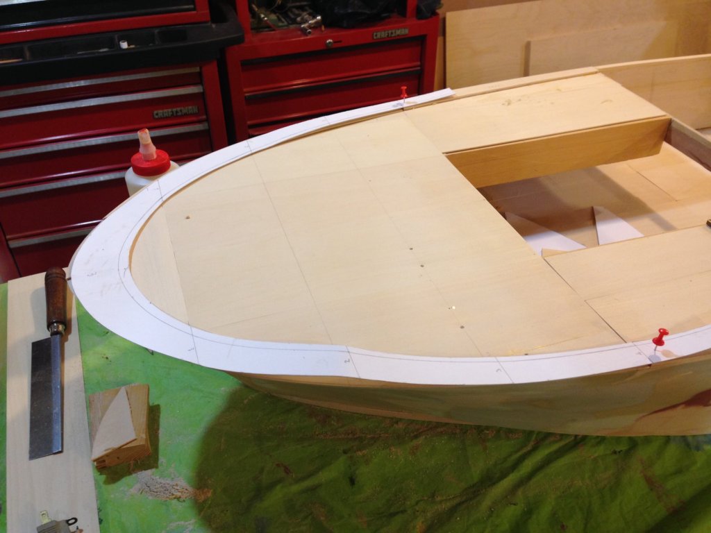
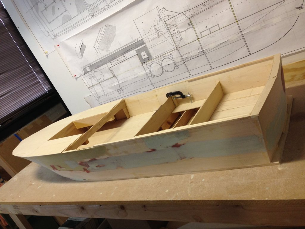
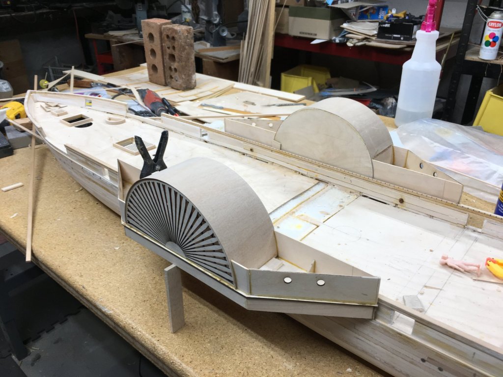
We moved the model to my workshop late last week and we find it much easier to work on. Lighting, room around the model and access to my woodworking tools (both hand and machine) make for smoother operation. Also the storage area at the museum was not air conditioned so summer work there was uncomfortable. The shop, literally is now a "model shop", stays at about 67 degrees with a RH of about 58%. That is the good news! The bad news is I have lost half my work area to this very large model! Once set up here we began anew. The photo of the aft section shows a propped up configuration of the air intake on the starboard side and in the foreground are the sub assemblies for the port side. There will be final fit and set in as soon as we get the "rails correct. The photo of the bow section shows the forward template set on top of the false deck for the "rail" around the deck. It rises from station 11 (at the engine compartment) from near zero height to the bow where it is nearly an inch high. We are planning on building it up out of 1/4" basswood and hand tapering it to drawing measurements. Notice the brass measurement blocks in the background. They will help define that height as we plane down the "rail". We did encounter a problem when we applied the bow template shown in the last photo to the bow area. Somehow our bulkheads at station 3 forward did not capture the flare out at the deck of the hull. It is extreme. No doubt this was to minimize water spray on the open seas at high speed. Underneath the template is a 1/16" thick basswood copy of that template attached to the false deck. It will guide us in fairing in the hull in the aforementioned area. Luckily it is at the correct level of the sheer line. Also the bow itself was found to be more bulbous that our first try at it. Out came the belt sander and now it is near true to form. It is still not ready for the "prom" but maybe just maybe it soon will be. We have called in some volunteers who will be working on the helm area and the forward gun turret. In regards to the latter there were no dimensioned drawings for the detail of that area. So yet another volunteer used the dimensions of the model 50 caliber machine guns to create a working drawing. My earlier lament about "few hands on board" seems to have had some effect. Joe
-
This is just another data point. I cannot refute what has been offered and only add the following. I just took a look at my 1983 built model that is in a case. I used bees wax to coat the lines which were linen. Upon up close inspection with a led flashlight I detect no attraction of dust particles. I will say that I built a temporary case/cover for it while rigging for dust protection. The former residence it was in ( and where it was rigged) had electronic dust control on the furnace and the house dust was minimal. You may want to consider better dust mitigation as it is beneficial beyond ship model rigging. Just a thought. Joe
-
Mystic Seaport has so much to offer that a partial day would need some upfront planning. It is just so engrossing that a "run through" would not do the museum justice. In addition Rt 195/95 traffic can be a challenge at times no matter the day. All said don't miss the museum. Joe
-
I revisited this last post as the reference to the fuel tanks was bothering me in terms of the amount of space forward of the newly placed bulkheads. I stand corrected the fuel tanks are under the deck area where the pilot would stand ( god help those guys as these boats had no armor to my knowledge around the tanks). The open space is actually access to the engines. Joe
-
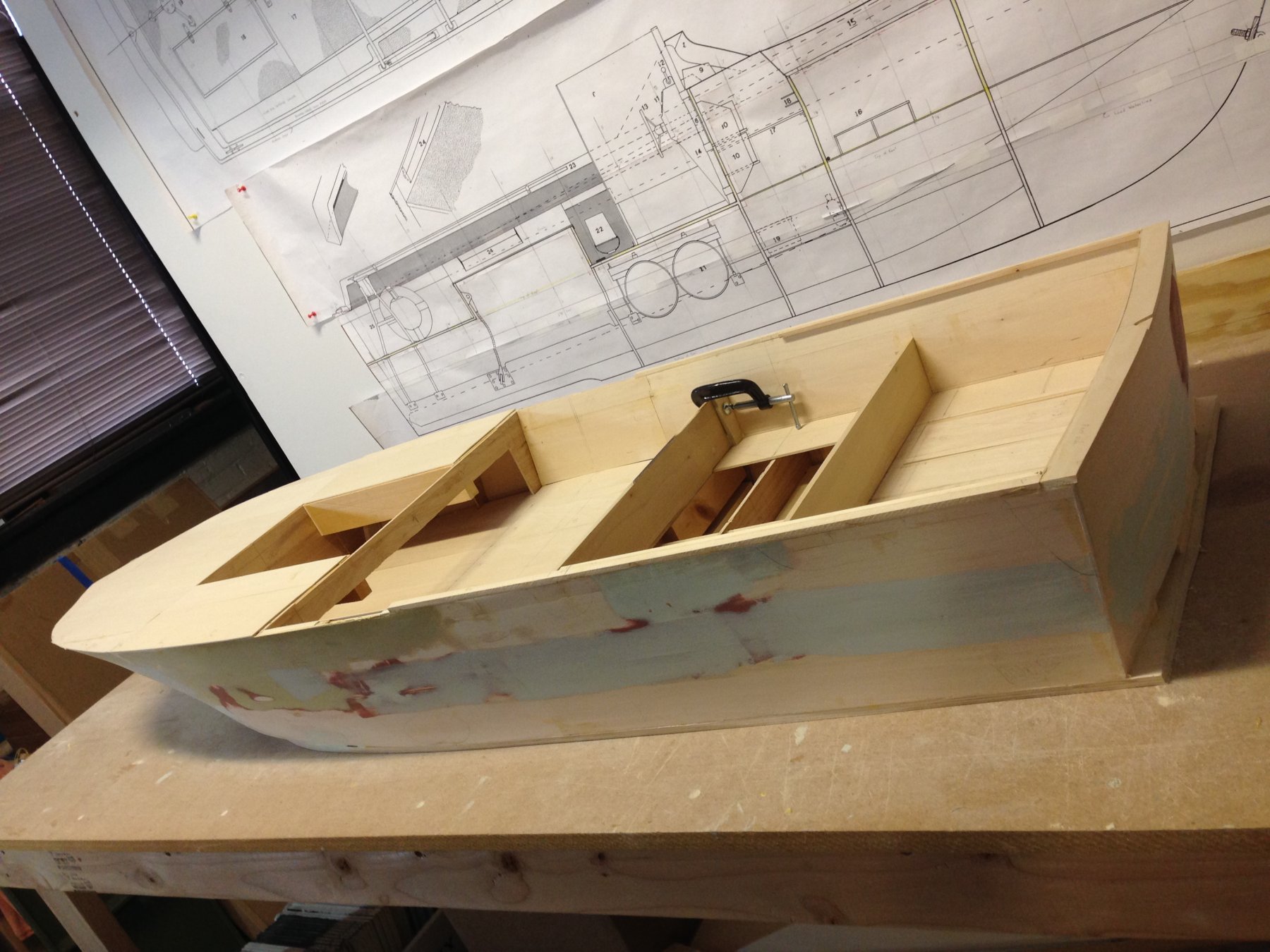
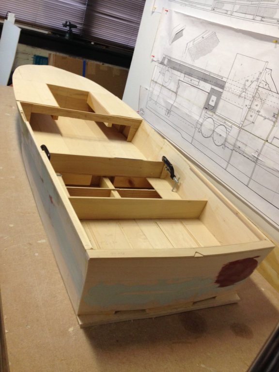
Yes, we have been off the radar since April. Too many projects, not many hands on deck and oh so little time have contributed to a slow down in the build. However I will lament no further as 4 of our group has been diligently but sparingly been at it since April. So in the attached photo is somewhat of a milestone for us. We have completed inner skins and applied a false deck forward of the control station. We have added the bulkwarks that will form the platform aft of the control station that conceals the engine fuel area. We have also added the aft rail and some of the side rail. In process are the engine air intakes (the dark area in the plan above) with one trial fitted today. The open area forward is the beginning of the twin gun turret which will be added in much more detail in the coming weeks. As soon as the air intakes are completed the contoured deck will be fashioned all the way to the bow. It is quite oddly shaped and we have had to constantly refer to the photos supplied by our friends at Patriots Point. As soon as we are satisfied with the deck construction the unit will be prepped for spray painting of the hull with primer. We have to get to that point soon as we are not permitted to use spray equipment even in this storage area.
-
It has many uses. A number of my woodworker colleagues use it to do inlay work for federal furniture and the like. One can even do arcs etc. with the proper home made jigs. Joe
-
Got it! Indeed Leopard I should have done what you did. I guess what was throwing me off was what appears to be milling marks on the face of the large billet. Joe
- 1,784 replies
-
- 3
-
-
- syren ship model
- winchelsea
- (and 1 more)
-
Forgive me Chuck, I have read and re-read your milling description and I am still wanting. In the first picture with the billet, is the grain running from L to R? If so then when you rip off a 1/4" sub-billet, say from that upper edge of the billet your "sub" billet has a clear face and the resulting planks are almost 1/4 sawn? Am I correct? And you can get the same results with cherry? And in terms of bending is edge bending any more difficult? Thanks. Joe
- 1,784 replies
-
- 1
-
-
- syren ship model
- winchelsea
- (and 1 more)
-
Self made clamps and jaws.
Thistle17 replied to ymperivm's topic in Modeling tools and Workshop Equipment
Thanks Bob I had forgotten this method of the scarf joint. On Cheerful there is even a plank in the bow that does not fall on a bulkhead so this would have been ideal. I certainly could simulate the butt joint even with the scarf. A bit extra work but given the results worth the effort. Joe -
Self made clamps and jaws.
Thistle17 replied to ymperivm's topic in Modeling tools and Workshop Equipment
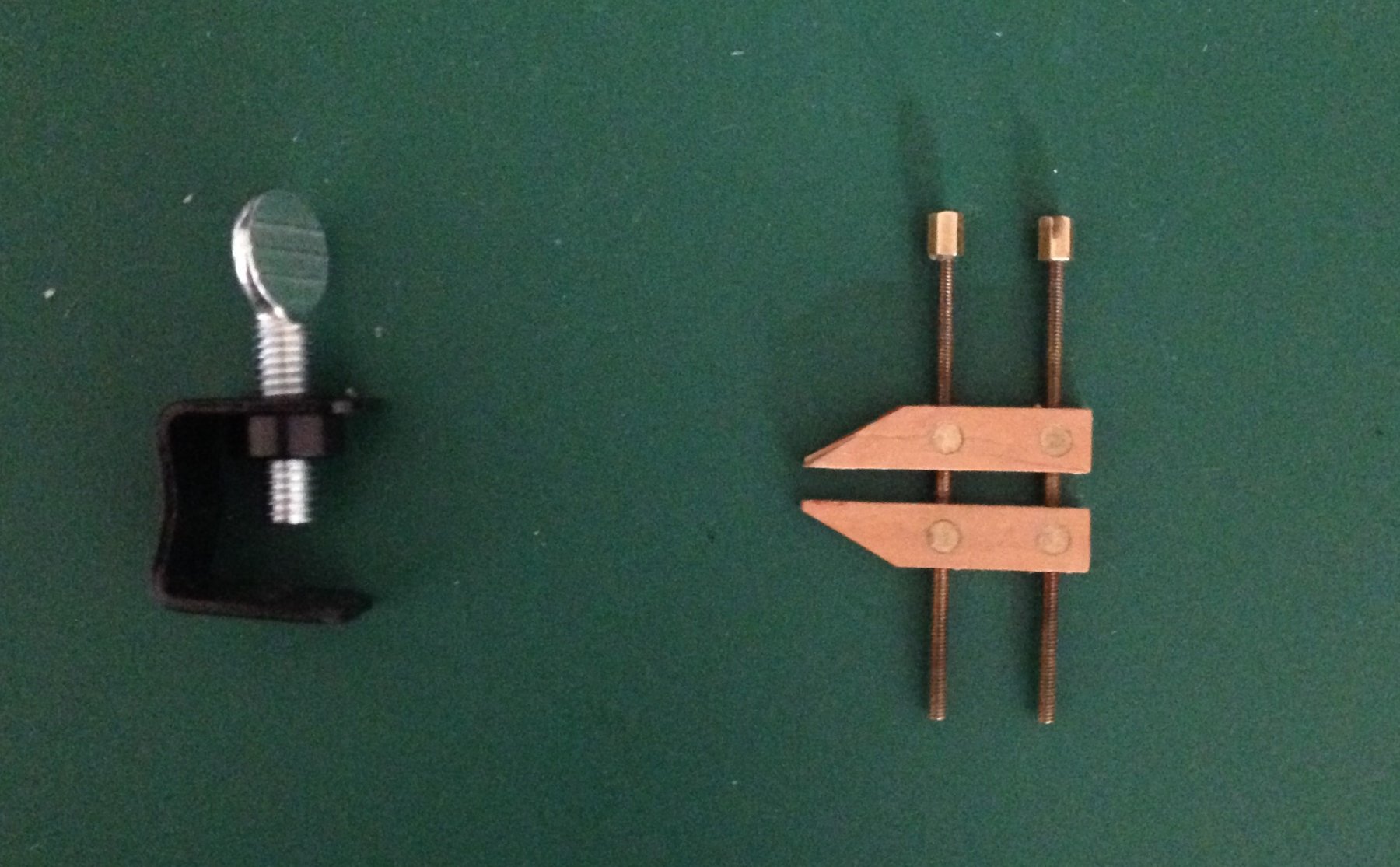
I still have so much to learn and become proficient at in terms of hull planking. In planking Cheerful I have been frustrated by certain planks not "laying down" to my satisfaction and then having to rationalize that I will sand down the offending neighbor to achieve a more acceptable plank to plank surface conformity. This has been especially so when laying down a short plank that ends on an intermediate bulkhead next to it's neighbor that has spanned several bulkheads. There is a natural bend or contour to the latter. While the short plank tends to be more or less flat across its terminating bulkheads. One is left to sand the area until surface conformity is achieved. Even pre-bending the short plank may not achieve desired results. I have used the miniature Jorgensen clamp shown in the early stages to clamp adjacent planks and internally add a small piece of glued veneer (with grain direction as in the plank direction) to smooth out the area. It works quite well. Now when one approaches the keel most clamps cannot be placed because of interference with the keel for example. In looking around I found the second clamp (in a set of 5) for less than $13 on Amazon. They are miniature welder's clamps for temporarily holding rocker panels etc. in place for alignment to doors and columns. The advantage of this type of clamp is that there is little to no interference in tight spots as mentioned. So piggy backing on "ymperivm's" lovely adaptation of miniature clamps here is yet another option. These are about 1/2" wide with a throat just about the same dimension. One could easily make these at home out of 1/8" thick aluminum channel of any width and achieve the same capability. Just thought I would share this. Joe
-
Jim I am sorry I haven't been on this model for some time other than to repair alignment of a bulkhead that went astray while installing them in poor light at the Strong Museum. I had thought of adding the extra detail between decks and then discounted it. Primarily as I am driving hard on Cheerful to finish hull planking and get on with more of the fun stuff associated with the model. I am not an accomplished plank installer but am slowly getting the hang of it so there is hope for me. I attended the 37th annual model conference in New London and picked up Syren's next kit, The Medway, and anxious to start that but holding myself in check. So things are starting to pile up. Essex still intrigues me and I think when Cheerful planking is done I will pick her back up and proceed on her hull albeit at a halting pace. I may have said this already I am going to do her above the plating line in Alaskan Yellow Cedar and below that I will probably use Bass. Just for economy sake. In regard to fillers I did Cheerful with Balsa fillers and ended up taking them out as planking below the wales proceeded as they just got in the way. It was useful in the fairing stage but became a nuisance thereafter. I was pleased with the blocking I installed on Essex, instead, as it made for quite stiff bulkheads. Joe
-
USS Agawam by Bill E - Scale 1:48
Thistle17 replied to Thistle17's topic in - Build logs for subjects built 1851 - 1900
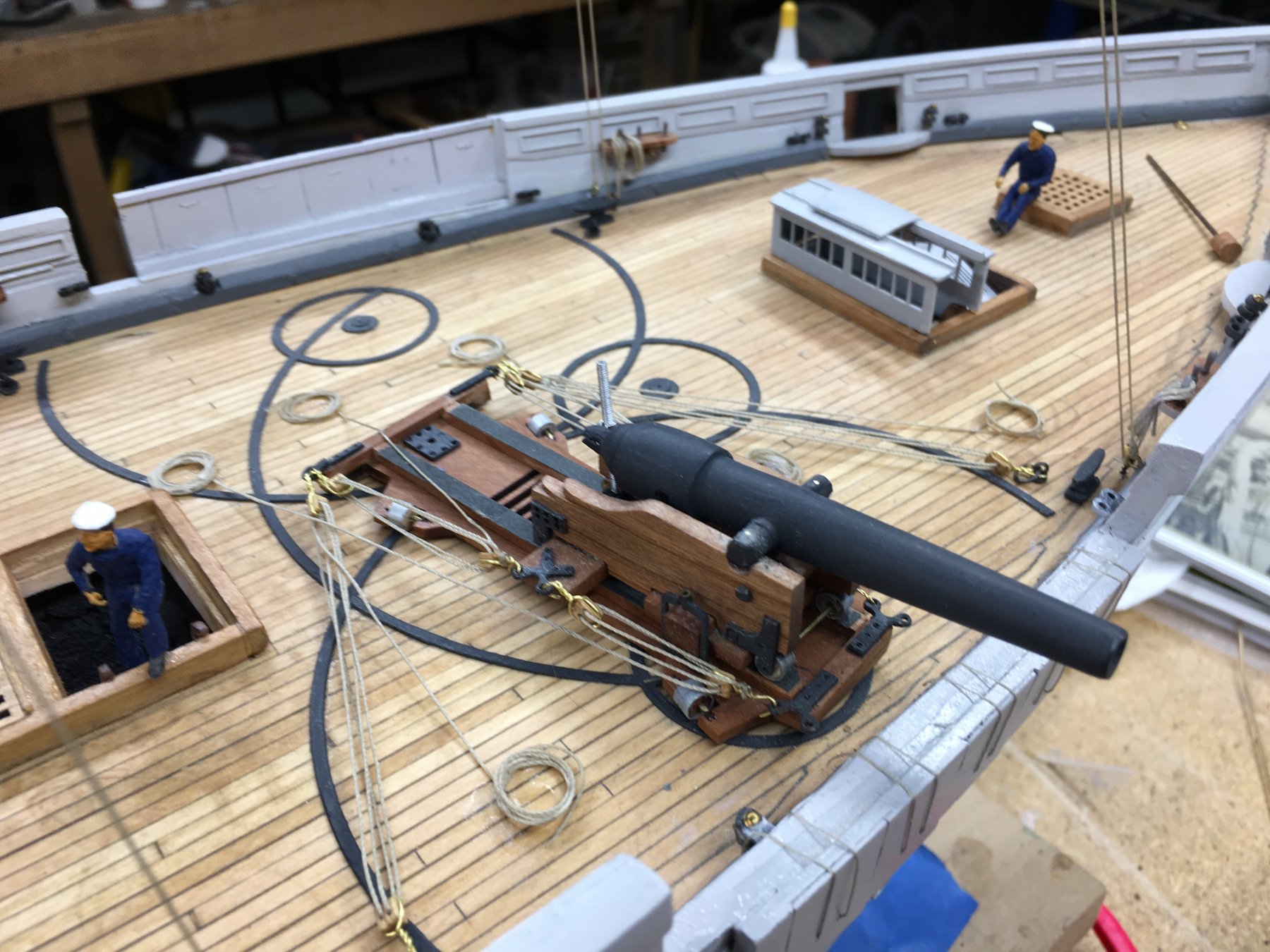
In the final stages of construction Bill had cannon and associated deck ware to consider as well as the lifeboats. The cannon were 100 lb, 24 pound and 12 pound. With all cannon Bill cast his own utilizing traditional methods as shown in below. Now the carriage for the 2 100 pounders is a bit unusual as wel as its aiming and tracking mechanism. I believe a 100 pounder must have weighed in at 10,00 pounds or more so the carriage had to be quite stout not only for the gun weight but for the charge. The attached pictures reveal Bill's progression in armament development. Here again Bill used computer aided design to develop the deck "track" for those guns. Note the removal of a section of the bulkwarks to enable cannon aiming.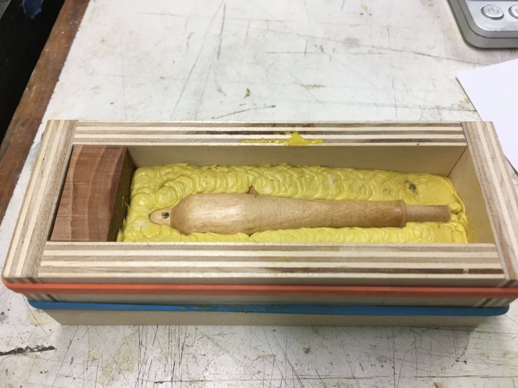

-
USS Agawam by Bill E - Scale 1:48
Thistle17 replied to Thistle17's topic in - Build logs for subjects built 1851 - 1900
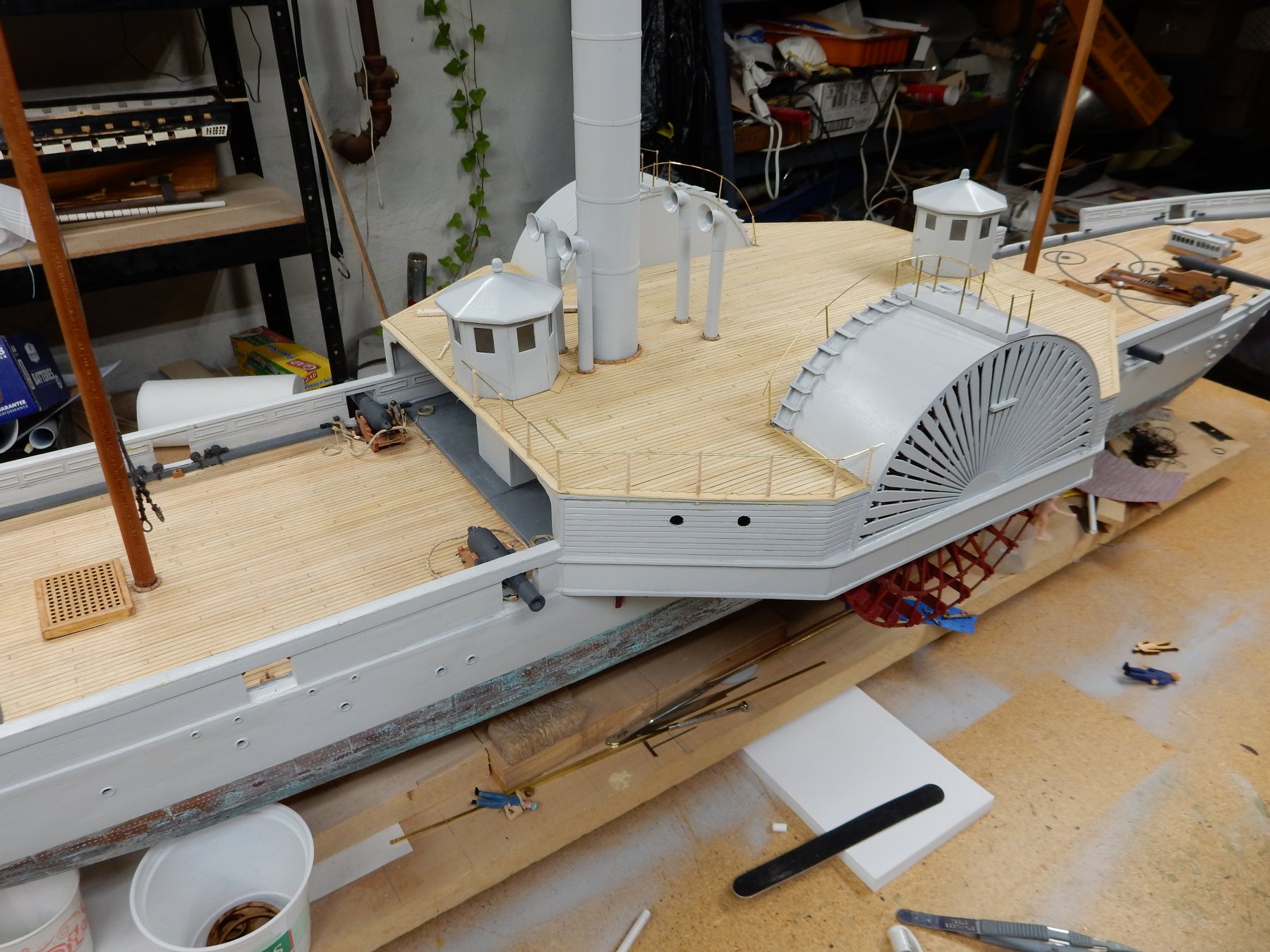
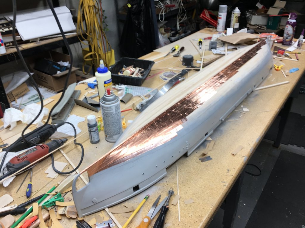
I will pass on your comment Johann. Bill will be pleased. As stated the deck furnishings were not elaborate so deck houses, mast towers, paddle wheel ladders etc were fairly straight forward. The twin deck houses were made from card patterns and replicated in basswood. Here deck planking is in place and some masting and rigging were started. I haven't asked Bill about the air vents but I will. I wonder if they were reversible for change of direction. One thing I forgot to mention is the rudders. They are replicated at each end of the vessel. When steaming forward the "front" rudder was locked in place. Note the patina on the copper foil used for the simulated plating. It is quite convincing compared to the virgin material. It adds so much to the overall appearance of the model. It does appear that there have been some accidents in dry dock in this picture as several workers or seaman have fallen off the build.
-
USS Agawam by Bill E - Scale 1:48
Thistle17 replied to Thistle17's topic in - Build logs for subjects built 1851 - 1900
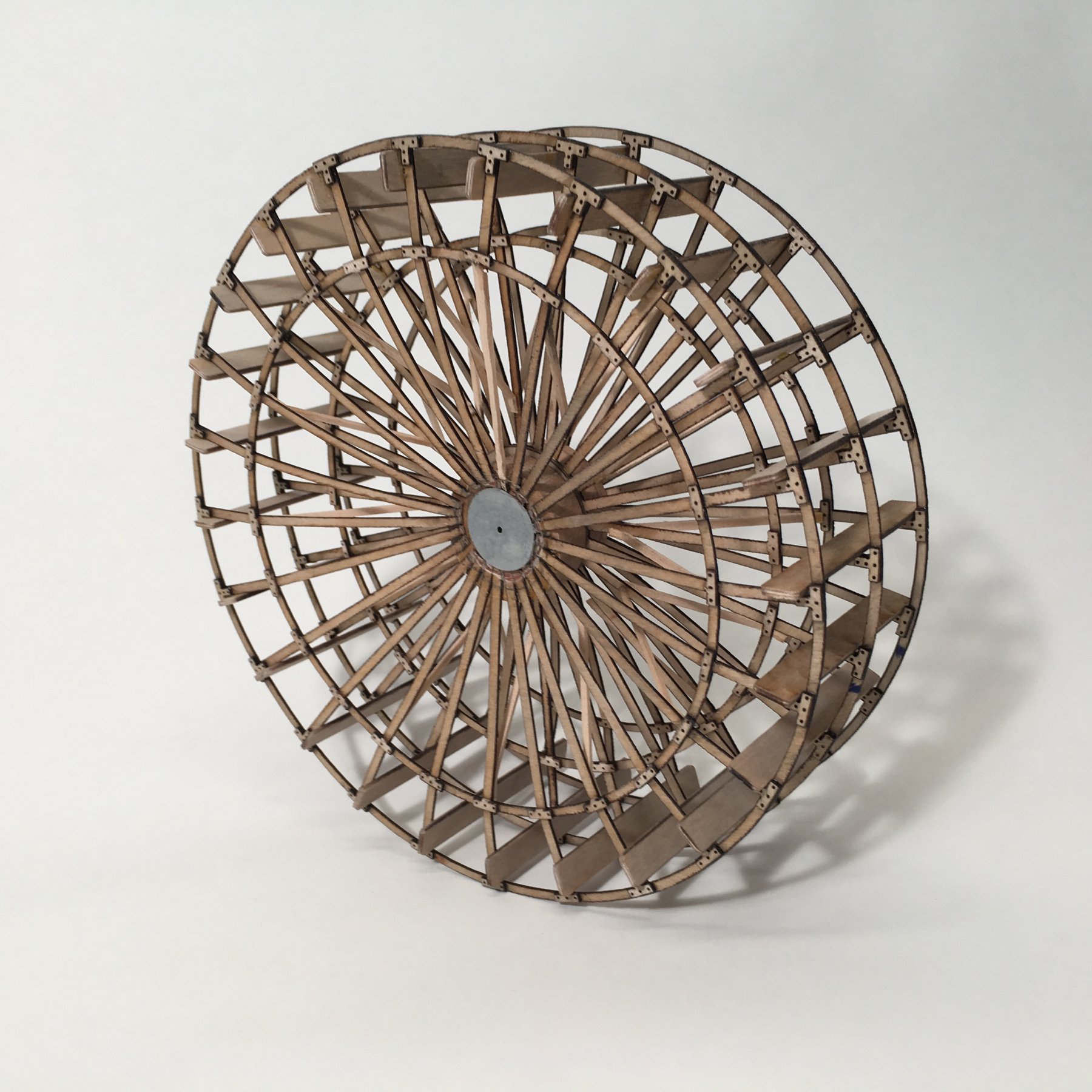
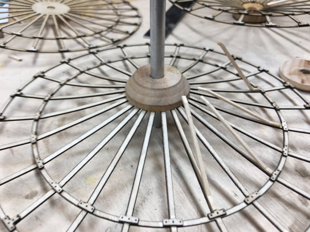
The most challenge Bill had was in the development of the paddle wheels themselves. Each unit is made up of three spoked discs separated at the center by a split hub. The hub area of the outer "discs" were not tied down but were left free to be bent inward and secured to the hub. Try making this free hand with these results. Note as well, the laser created re-enforcing plates for the radial elements. Technology and good ole Yankee Ingenuity at work here!
-
USS Agawam by Bill E - Scale 1:48
Thistle17 replied to Thistle17's topic in - Build logs for subjects built 1851 - 1900
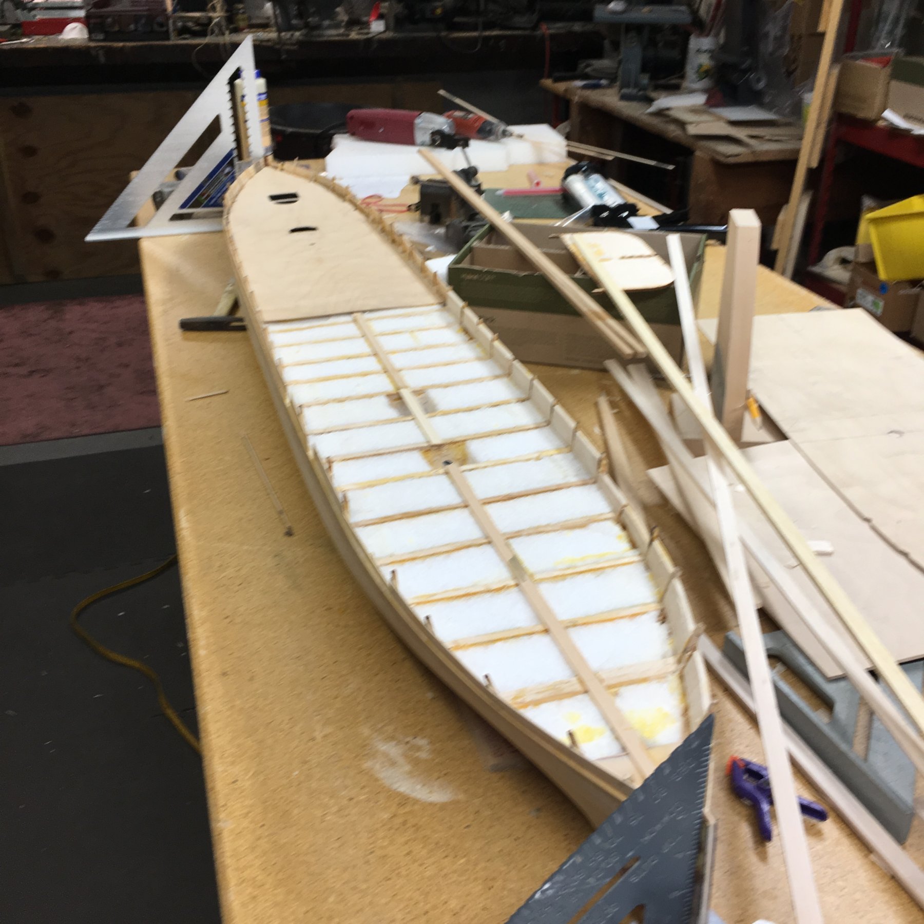
Hull planking was dispatched fairly quickly as the lines of the hull make for easy work amid ship and with symmetrical bow/stern. Open cell foam was added between bulk heads for increased rigidity after which false decking was added. In the second photo one can see that the deck detail is not overly complicated but are a bit massive so attention to detail here was paramount. The outside paddle wheel grill, if you wiil, was designed via Corel Draw and laser cut. In a case like this, that technology is a blessing!
-
USS Agawam by Bill E - Scale 1:48
Thistle17 replied to Thistle17's topic in - Build logs for subjects built 1851 - 1900
We all have our methods and materials we favor in model building. In the attached photo you see that Bill has begun planking the complete hull for Agawam. Do you notice the yard sticks in the foreground of the photo? Do you think they are for measurement? Well think again. They are his planking in the raw! Sometime back Bill came upon a supply of yard sticks from some manufacturer. He bought an abundant supply of them (at the right price) which he has milled to fit his needs. They are of basswood (or similar material), are quite straight and void of imperfection so they make fine 3 foot length stock for planking. Bill is always looking for solutions from all sectors.