Thistle17
-
Posts
1,042 -
Joined
-
Last visited
Content Type
Profiles
Forums
Gallery
Events
Everything posted by Thistle17
-
 Ab I cannot wrap my head around the fact that this endeavor was done just for fun. The skill, depictions and execution are just stunning! The works of countrymen artists such as Vermeer and others always give me pause. And I have to say so too does this work! Joe
 -
Ok Glenn I am sending mine onto you as you have the method down perfecrly!!!! Joe
-
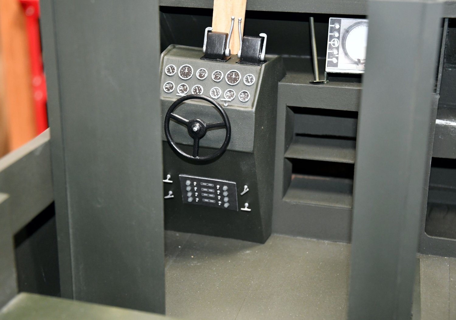
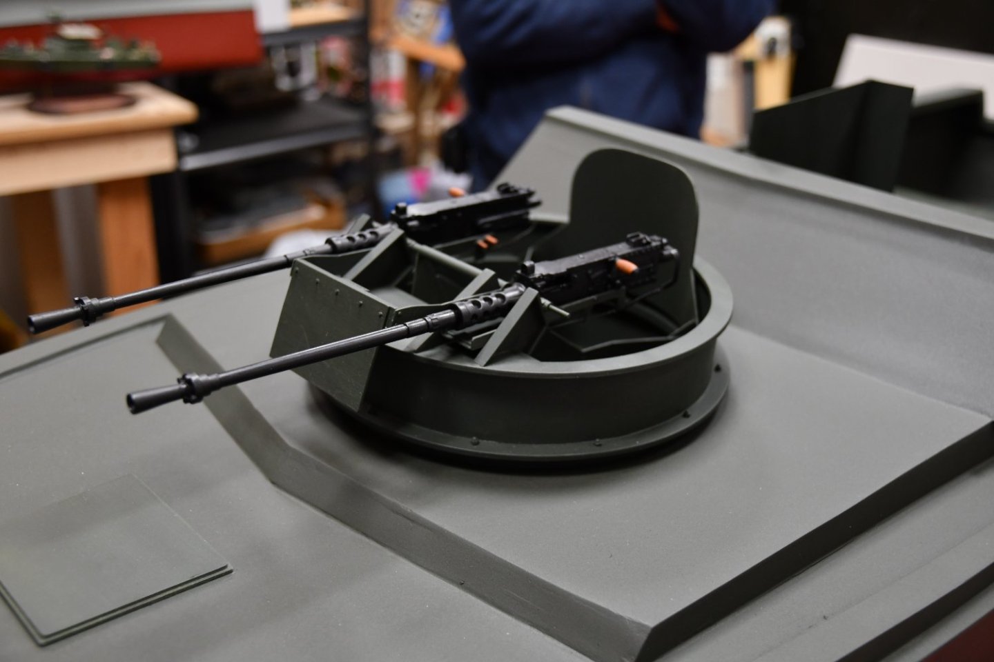
Now that the model has been moved back to the museum it is receiving the attention it deserves. The director of the museum supported the effort by purchasing an airless paint gun with adjustable nozzle patterns. Since the hull had more than enough time to cure the oil thinner" based paint it was decided to spray the hull with latex. I must say it was a hugh improvement over the earlier attempt. Chuck, the director was able to keep a wet coat and as noted the results were quite pleasing. After months, no years, of a bare hull we could not resist dry fitting some of the major components to give ourselves a boost to "bring the project home". Shown in the accompanying photos we temporarily placed the pilot console and the armament sheilds in the helm area. And of course we had to witness the forward gun tub resting in the hull. Also note the venturi is now in place and some of the helm area braces (not shown) have been added. It is amazing how even the little things contribute to the character of the project. Standby as we will be installing signal and radar masts, attennas, aft gun platform, canopy framing and all the other previously mentioned elements. Joe

-
A masterwork! I was fascinated with the hull construction. The "plating" was just beautiful. Such an interesting subject as well. Joe
-
I have tracked your work since I discovered this site some years ago. Your work is always inspiring. As the saying goes "love like youth is wasted on the young". One might draw a comparison to ship modeling and modelers. General health including sight, dexterity and the like, most needed for modeling alude us as we age and when we are most apt to be into this pursuit! Wishing you a speedy recovery. Be patient with it. Joe
-
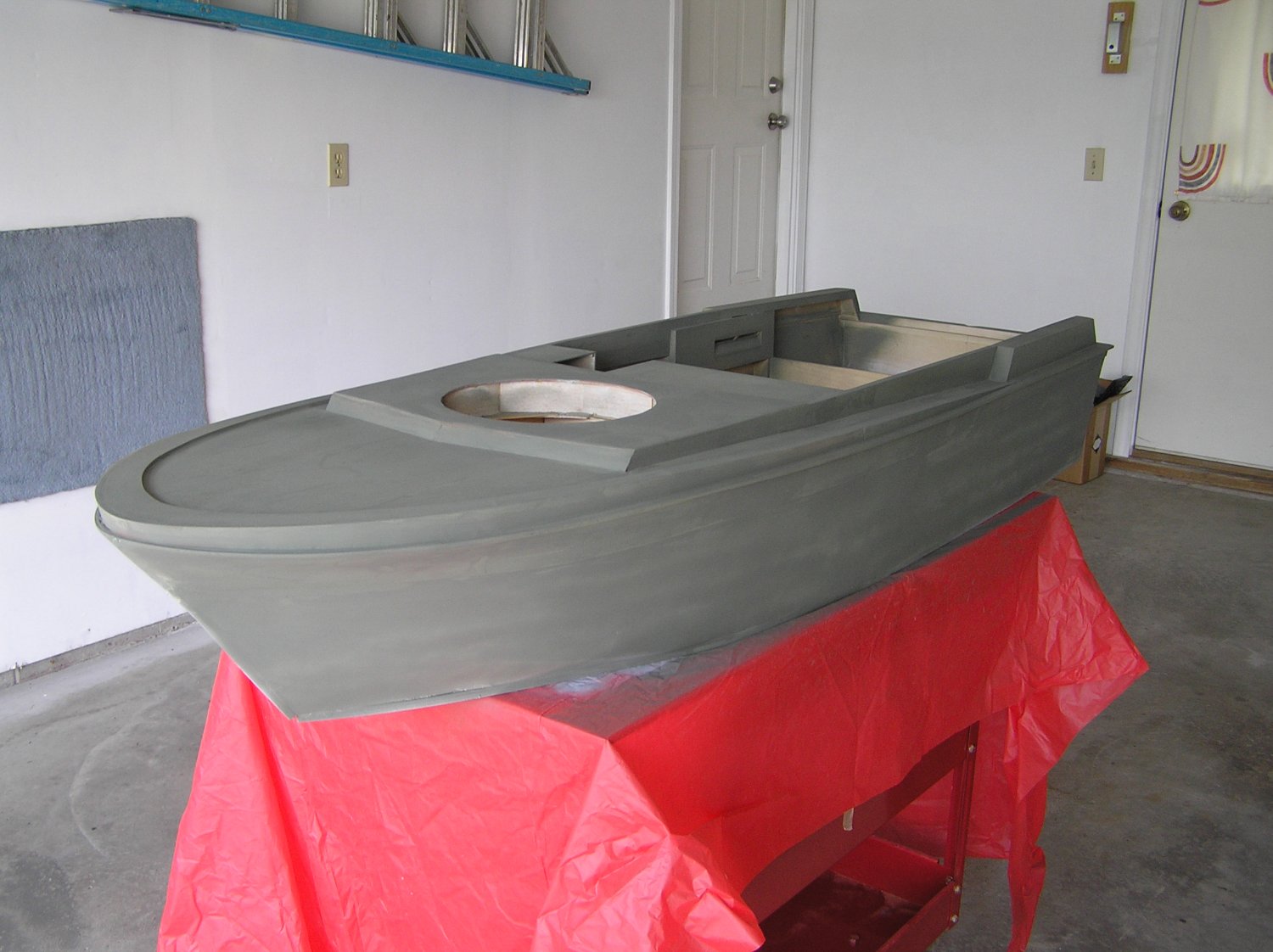
After nearly two years in my basement and garage the hull for the PBR has gone back to the museum for final detailing. It is a mixed milepost. The venturi or cowling in the helm area was installed and glassed in for a finished look. The whole area was primed and painted. Unfortunately we used spray cans of the paint, a flat enamal. Unfortunately the spray pattern was too narrow and it was almost impossible to get a full wet coat. Quite disappointing after all the work we put into the glassing , glazing and fairing of the hull. A quick stop on the way back to the museum at an auto body shop for a quote was disappointing. The owner quoted an $800 charge!!!!!! Looks like we are going to break out some home gear to have a go at a final wet sand and repaint. Very few deck appointments need to be completed. All cleats, armor shields, canopy frames, masts, helm, radios, scope and of course the forward gun tub and aft gun are ready to install. We just have to get past this hull paint situation. Who knew this journey would be so troubled. Joe
-
Such a rich, warm effect achieved with the wood choice and color added. Joe
- 642 replies
-
- 2
-

-
- winchelsea
- syren ship model
- (and 1 more)
-
As they say Glenn copying or following another's work is well deserved flattery. Your work is in my list of one's to follow! Joe
-
A guide to using MSW
Thistle17 replied to James H's topic in How to use the MSW forum - **NO MODELING CONTENT**
Wonder of all wonders. Using the Google Reset function worked this AM. Resetting each element, cache, cookies, history independently did not do it. Thank you Mark! JOE -
A guide to using MSW
Thistle17 replied to James H's topic in How to use the MSW forum - **NO MODELING CONTENT**
Well, it appears that while I was away and using my laptop I used another browser. That browser automatically admits me. I tried clearing its cache, cookies and site preferences to no avail as Google Search still requires me to log in. I will continue to work it. Joe -
A guide to using MSW
Thistle17 replied to James H's topic in How to use the MSW forum - **NO MODELING CONTENT**
Hmmm! Tried this 2X and it did not work. Any other suggestions. Could it be it still recognizes my laptop id? Joe -
A guide to using MSW
Thistle17 replied to James H's topic in How to use the MSW forum - **NO MODELING CONTENT**
James I have been a member for over 5 years but seem to have to sign in each time I enter the web site inspite of clicking the "Remeber Me" selection. This is new after I returned from a trip last week where I used my laptop rather than my desktop which is the most frequently used device. Joe -
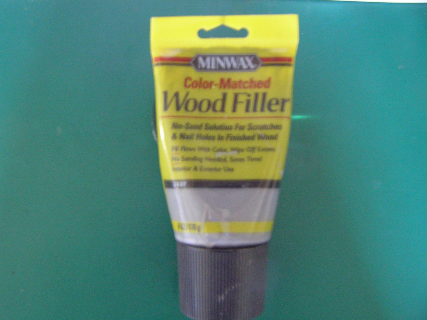
As indicated to Pete we are pushing to get the model back to the museum prior to winter with the top sides painted. An impediment to that goal has been the refinement of the hull et al surfaces. Between weather extremes of hot, humid to dry cool some seams have opened up under prime. This is not a surprise as it is a wood model after all. And because of its size these voids just scream out at us. I have been searching for a suitable glaze or filler for these voids that was easy to work with. This has been an ongoing search. Well 2 weeks ago I stumbled on a product. The one shown is easy to apply, can be damp finger controlled in spread, dries hard in a day or so, fills small voids and cleans up with water on hands and applicators. And almost as importantly it does not seem to dry up in the tube like my other tube wood fillers. The one last test is compatibility with primer and paint. It is even a grey color! Joe

-
Well a very grateful thank you for sharing this trove of info. As we are nearing the detailing stage of the model this should prove invaluable. We usually do try to do continued research on this project because of it's storied past and the interesting way ( not withstanding its confounding and progressive disclosures) it was buil and modified during service but of late it has been an off/on order of build/ Joe
-
Thinking back to when such a technique was not available one has to admire those builders of "yesterdays"models. You continue to refine laser fabrication each time you advance this build. Your techniques put this project within reach of so many more of us than was possible in these past few years. I hope everyone appreciates your engineering efforts. Joe
- 1,784 replies
-
- 3
-
-
- syren ship model
- winchelsea
- (and 1 more)
-
Beautiful execution Glen! Inspirational! Joe
-
And thank you Glenn for the encouragement and alert. I have been looking ahead and have anticipated the need in this area. I am plodding ahead with the gun port lower sills as I write this. Indeed boring and annoying as the placement of those members is such a pain. I have found that the only good way to fit those members is to use my Byrnes sander and carefully tune them to fit. It is surprising that with all the time I took with the bulkhead positioning that I find when using Chucks measurement of the members right at the strong back by the time I get out to their extremities they are quite different! I have had to clamp them in place to hold their position in most cases. I will also add the members in the areas where the gun ports are absent to make the assembly more rigid. One amusing thing I found was that my "clever" method to hold the fragile uprights in place with spot glued battens had to be removed to make the sill and filler install work as I had no lateral movement capability.. Seemed like a good idea at the time! I do have one question that maybe folks can help me with though. I have yet to run across an indication of just how thin the inside of the uprights of each bulkhead should be sanded after I finish the hull planking. Is there a measurement stated somewhere? Joe
-
Thanks Frank! I may be a slow learner but all the wonderful work others have shared keeps me motivated. I marvel at those amongst us who can pull it off the very first time. Joe
-
Amongst other things I have been stuck in my own follies of late so just getting back to witness your handsome model and expert work. That wood looks so warm in those pictures and that stove is just a masterpiece! Joe
- 642 replies
-
- 1
-
-
- winchelsea
- syren ship model
- (and 1 more)
-
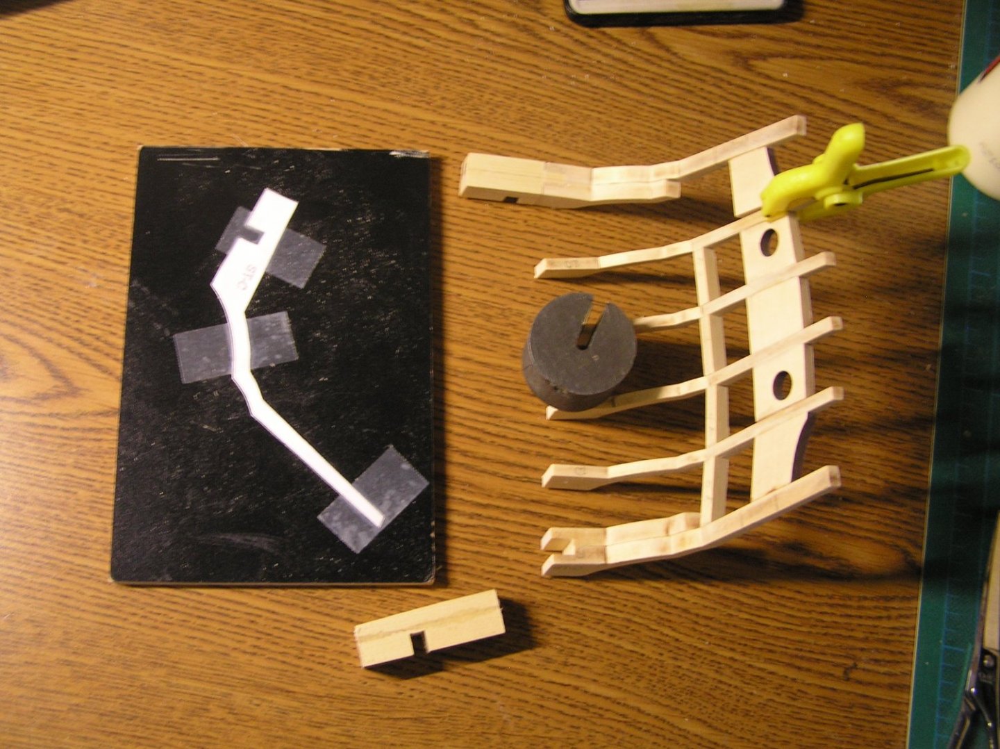
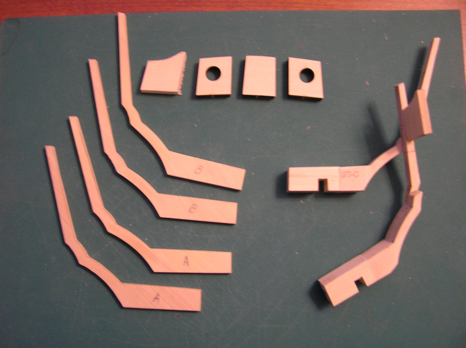
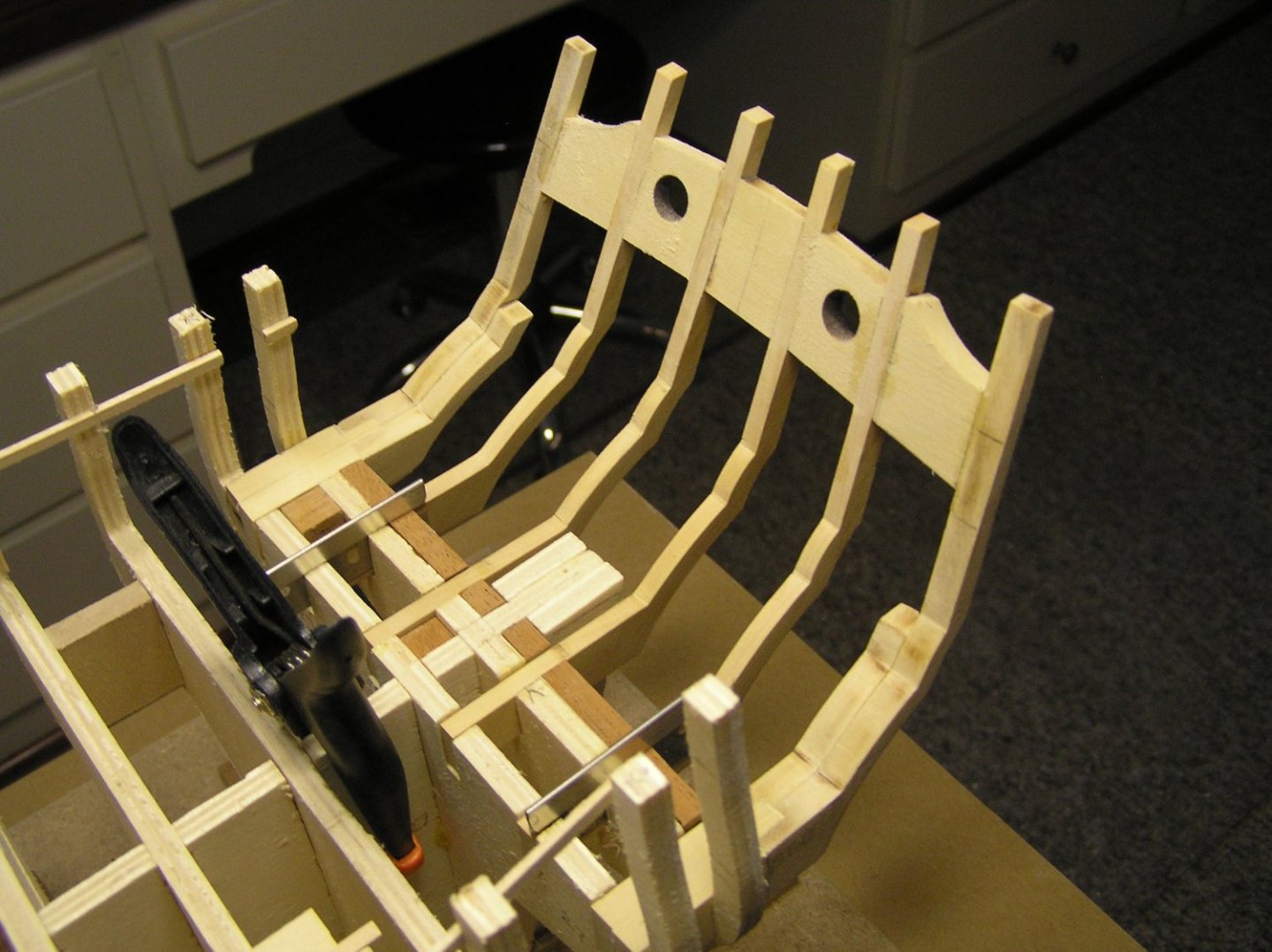
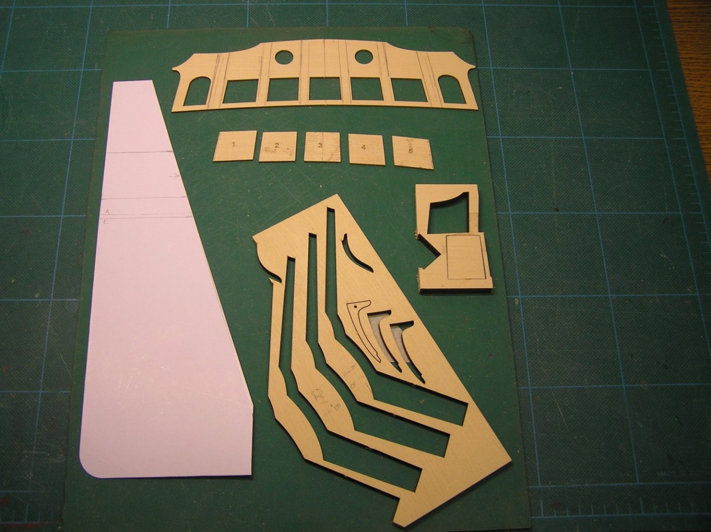
After some 20 days of on and off focus on this build I finally believe I have a worthy transom construction that will carry me through. The first photo shows the transom sub assembly (sans the lower sills) dry fitted onto the frames. If you have been following along my path to this point you are aware it has been a circuitous and not without folly journey. Fundamentally I just did not appreciate the criticality of the transom positioning in relation to the quarter galleys. So anyone approaching this area should be fore warned. Having said that and for what it may be worth to others I would like to share my methodology. I would not say it is the definitive way of doing things for there are a number of ways within the build blogs that worked but for me it replaced the awkwardness of paper patterns especially when removing and replacing the assembly. In stepwise fashion here is how I approached the construction: 1. After making the new frame members and repairing the P and S outer ones I repositioned them in the registration slots on bulkheads #27 through #29. My slots were a bit sloppy from my first try at building the transom so some shims were needed to hold them in place. 2. I then took the transom laser cut outer 'skin' shown in the second photo and clamped it to the outside of the frames. It was positioned so that the relief around windows was equal. The "fit" templates (1 thrugh 5) were then placed in between the clamped frames and the whole was adjusted accordingly to ensure that this piece was placed vertically (aligned at the bottom to the topside of the upper edge of the counter) and again symetrically around each window opening. 3. Lines were traced down the inside of the transom piece where the frames should align. See the markings on the inside of the transom piece. You will also note a center line on the transom piece. 4. Starting with the inner 2 frames the filler piece was sanded to fit the exact opening. It was then glued in place to both 'A' frames. It too was marked with a center line. 5. This assembly was removed from the model and the aft side was rough sanded to nearly its final thickness. 6. This sub assembly was returned to the model and once again aligned with the transom piece via the premarked center lines. 7. The next transom filler piece was edge sanded (with the appropriate taper) using the guide on sheet 1 of the plans and trial fitting on the model such that the port hole concentricity was achieved. This is a bit tricky but doable in carefully repeated steps. The registration guide supplied (i.e. #2) was used to ensure that the sizing was proper. It was then returned to the model and glued to frame 'A' only. 8. Once the glue had securely bonded (I take extra clamp time when edge grain is glued to face grain) I then sanded this added filler off the model to near flatness to its frame. I then reclamped the transom filler to the frames ensuring alignment and clamped the 'B' frame to this new sub assembly to check for edge trueness, port hole alignment etc. If satisfied I glued frame 'B' to the sub assembly. 9. This same process was used for the port side filler of the same type. 10. Iteritively, this process was repeated for the remaining frames and fillers. 11. I must repeat that all along the way I used the spacer registration pieces 1 through 5 repeatedly while fitting and during assembly. And as importantly I used the angle template made from the drawing to ensure that the final assembly would have the correct tilt from vertical. 12. Lastly if one measures off the drawing where the inside of transom piece 'C' must tie into bulkhead #28 with the horizontal member that becomes the header for the quarter galley passage way you will find that it has to be 61mm across its top. Before final gluing that should be checked P and S. Joe Just an editorial comment: Chuck must have had me in mind when he made duplicates of all the transom filler pieces. I used and went through them only having to make the outer ones from scrap on the originally supplied parts blank.
-
Progress on the PBR hull in just the last day. Out of the basement it came on a very arrid, warm day and we managed to get nearly a full coat of primer on the topsides, insides and some of the hull area at the rail. Not surprisingly voids or "holidays" as the painters trade calls them popped. These were filled with Nitro Stan glazing compound and will be wet sanded and primed once again when the hull is dry. This hull has been in the basement since early days of the Covid lock down and it is time for it to go back to the museum for further outfit. I will be so happy!!!! Note that this primer is amazingly tinted like the top coat so it should be less of a problem for us to finish caot. Joe

-
After preparing all the sistering planks to facilitate use of the existing transom framework I had second thoughts about this method of repair. Knowing that a poorly fit and aligned transom implied problems, possibly unrecoverable, when it came time to include the quarter galleys I scrapped the idea. Instead, using the kit blanks for the intermediate frames I made new ones of boxwood. As stated I never throw away the "blanks" for just such a reason. I remade frame pairs for 'A' and 'B' elements. They were rough cut on my scroll saw, sanded on my disc and drum sanders to the traced lines and they were hand tuned with files and chisels. Finally they were ganged together and fined tuned further for conformity. By the time I finished I had yet more respect for the accuracy and repeatability of laser machining. I was able to repair the 'C' and 'D' pairs as stated earlier so with the spare filler parts included in the Chapter 1 ensemble I will start again to assemble the transom using selected techniques developed by those wiser than me. Joe
-
Nicely done Gary. I also like that bow filler. Besides adding more surface for adhesion it makes the "sweep" so much more true. Joe
- 389 replies
-
- 2
-
-
- syren ship model
- winchelsea
- (and 1 more)
-
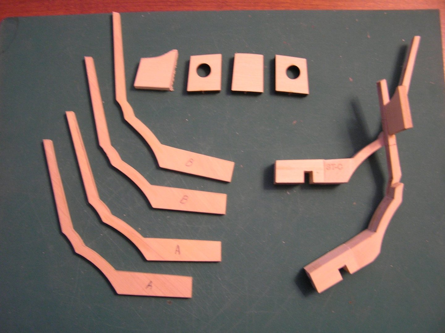
As I was preparing to build anew all the elements of the transom it struck me that I might try to salvage the transom that I had sawn off on my last attempt at assembly. Since my transom angle was the driver for the removal it seemed to be a waste to just abandon it without trying a repair. I first trued up the cutoff ends of the port and starbaord C/D frames. Then I mortised into the cleaned up ends a deep enough mortise to give a tenon a substantial seat but not too deep as to protrude aft. Having saved scrap cedar from the kit I glued up "extenders of the same material thickness and let in the registration socket in each. One "extender" was cut to length (including the tenon length) for the starboard side. It was glued up using the cutout template for the element alignment. Since it had broken away from the transom full assembly it was easy to machine. The fuller assemblage was a bit awakward but it did fit my mill vice with some creative clamping. The port side extender will be cut to length and milled in a similar manner. The mid transom frames would be more difficult to repair with them in an assembled manner so they will be treated differently. Since they require simple extenders I will "sister planks" of appropriate dimension to A and B frame ends. Having done so I will open up the respective bulkhead slots and reinstall the repaired transom. And this time I will use the template guide I fashioned. Hopefully I will be back in business soon. Joe