jbelwood
-
Posts
217 -
Joined
-
Last visited
Content Type
Profiles
Forums
Gallery
Events
Everything posted by jbelwood
-
 Thanks Nic. Next up is either the walking beam or the officers quarters. John
 -
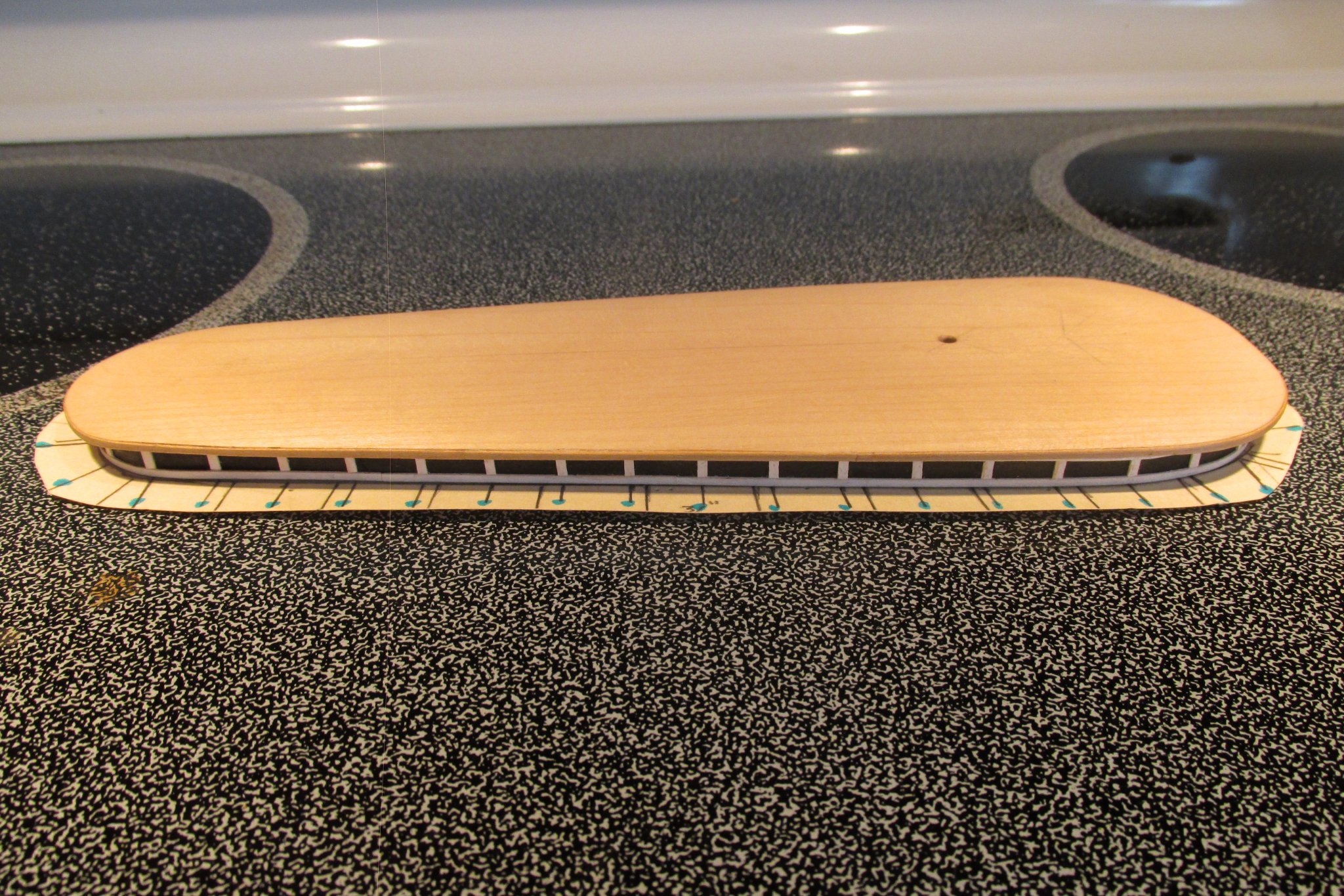
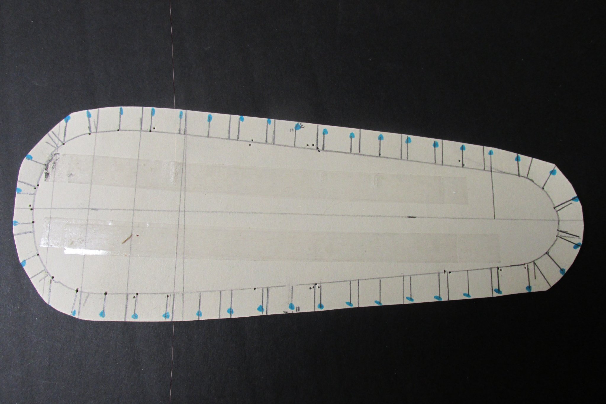
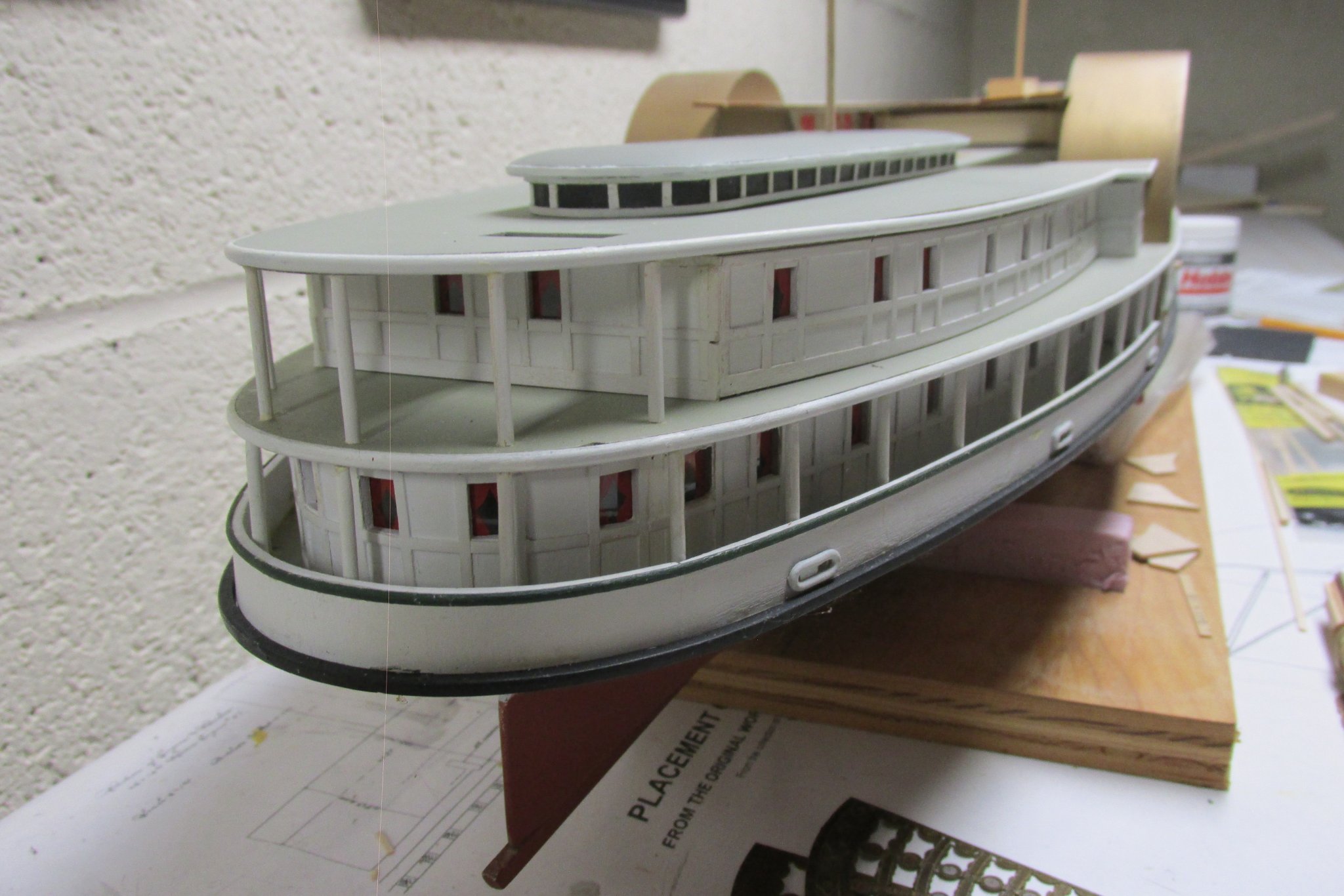
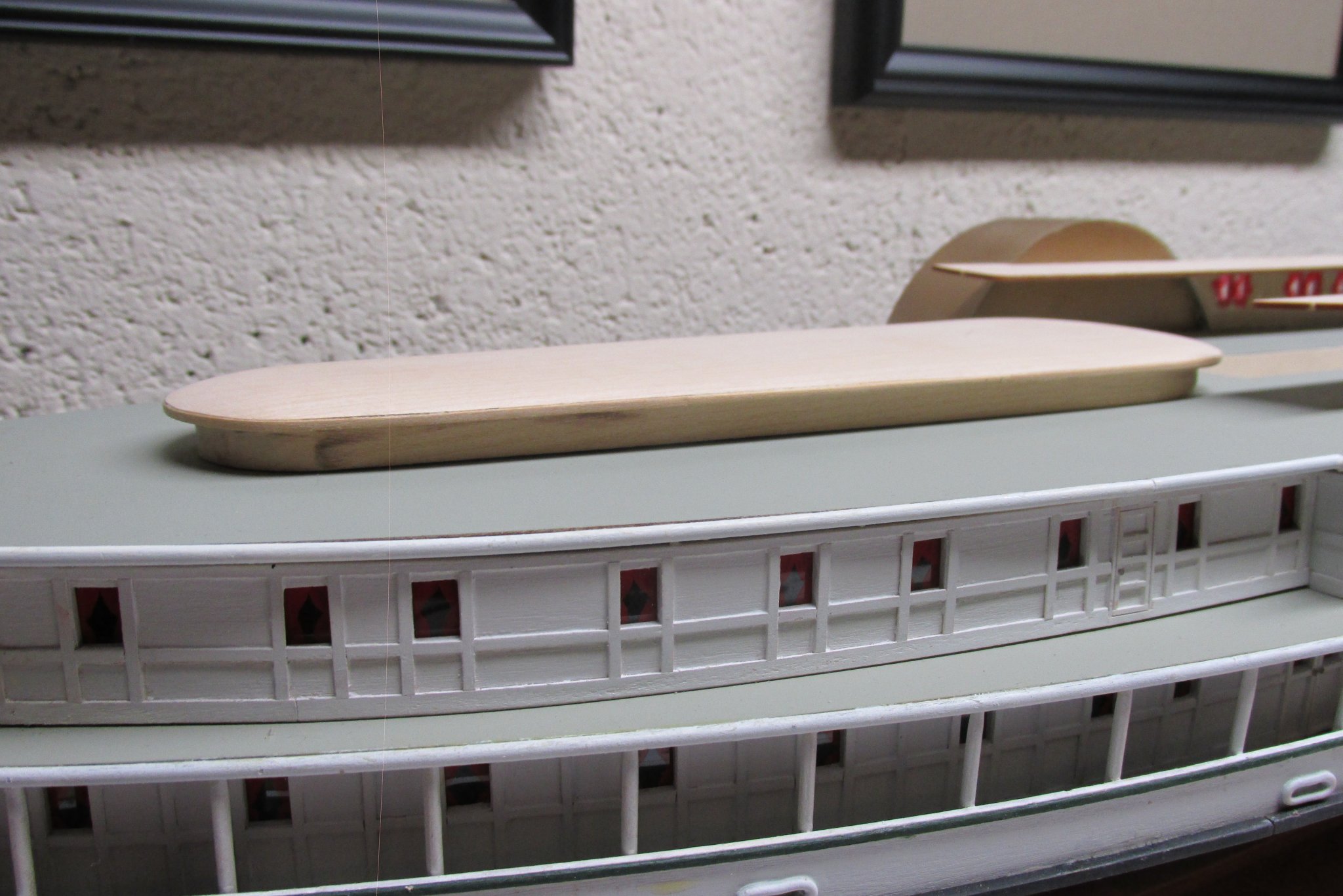
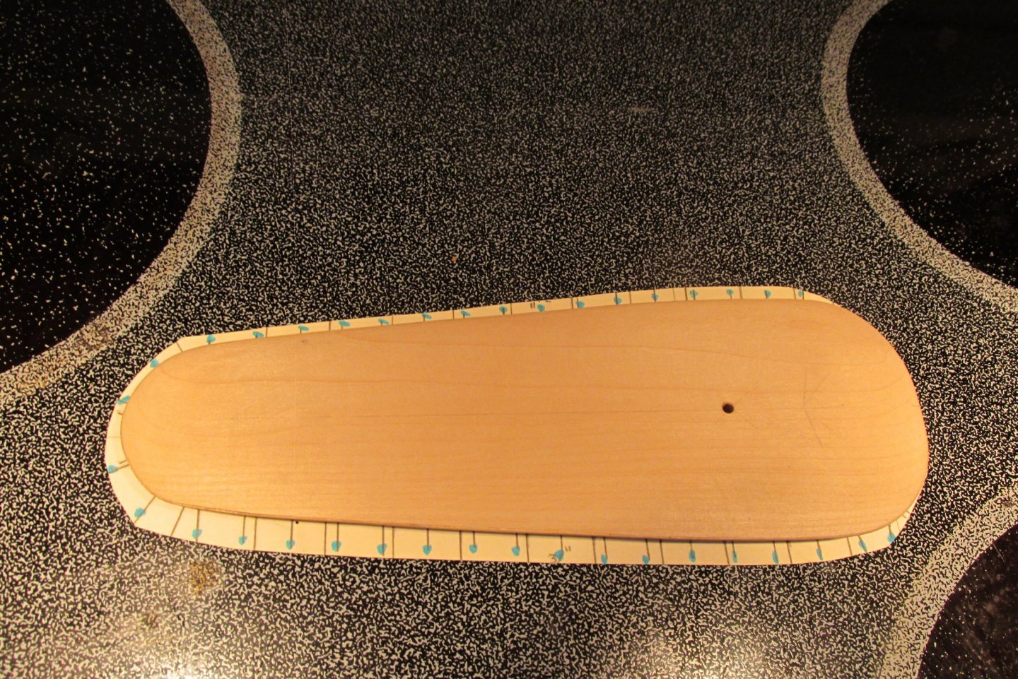
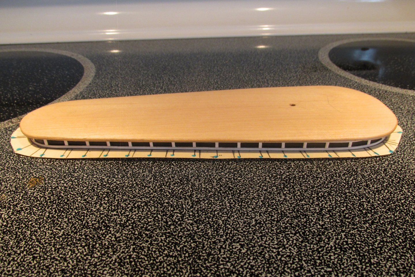
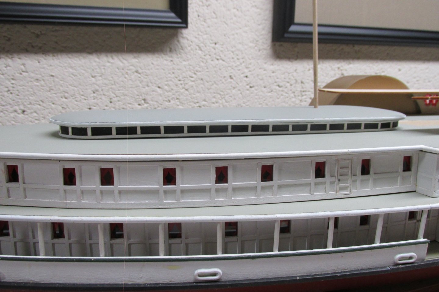
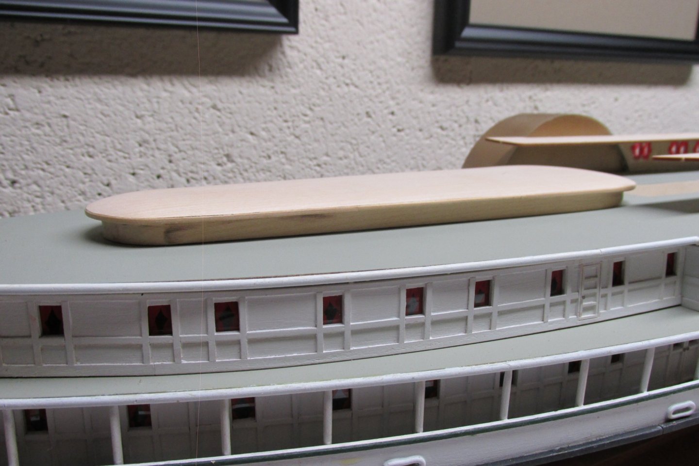
Finished the Portlands skylight. I started by making a pattern of the rabbeted base on a piece of manila folder. Decided to have the vertical window framing 1/2" apart. Measured around the perimeter of the pattern and drew a line every 1/2" and place a blue dot on each for identification. Here you can more readily see the idea. At this point I painted the window wall with Floquil Engine Black. When dry, I burnished it with a soft cloth which produced a nice sheen. Fastened the pattern to the base with double sided tape and added the frame work. Used 1/32" x 1/16" bass wood strip along the base and uprights. Used 1/32" square where the window wall meets under the roof. Painted the roof Floquil CN Gray with a white stripe around the edge. Not glued down yet but here it is finished. John Elwood Stratford, CT


-
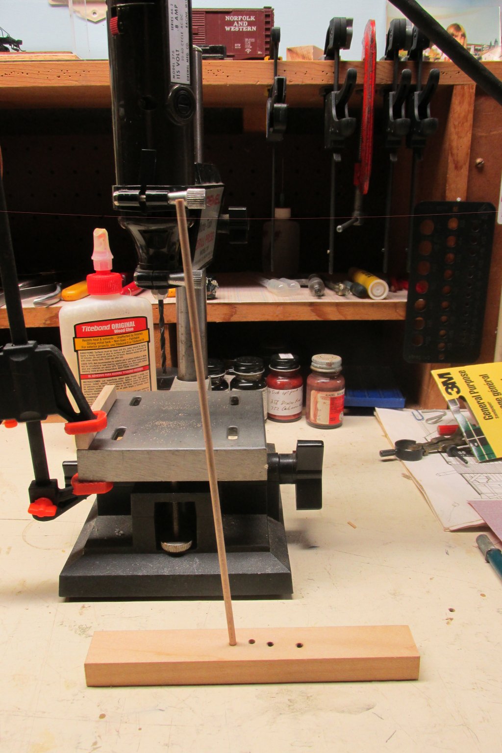
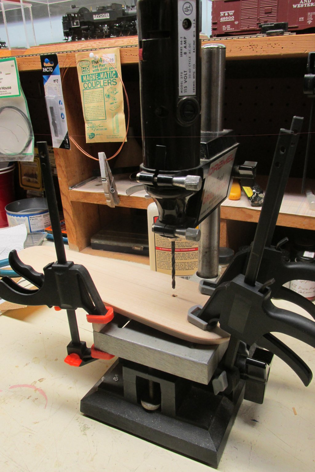
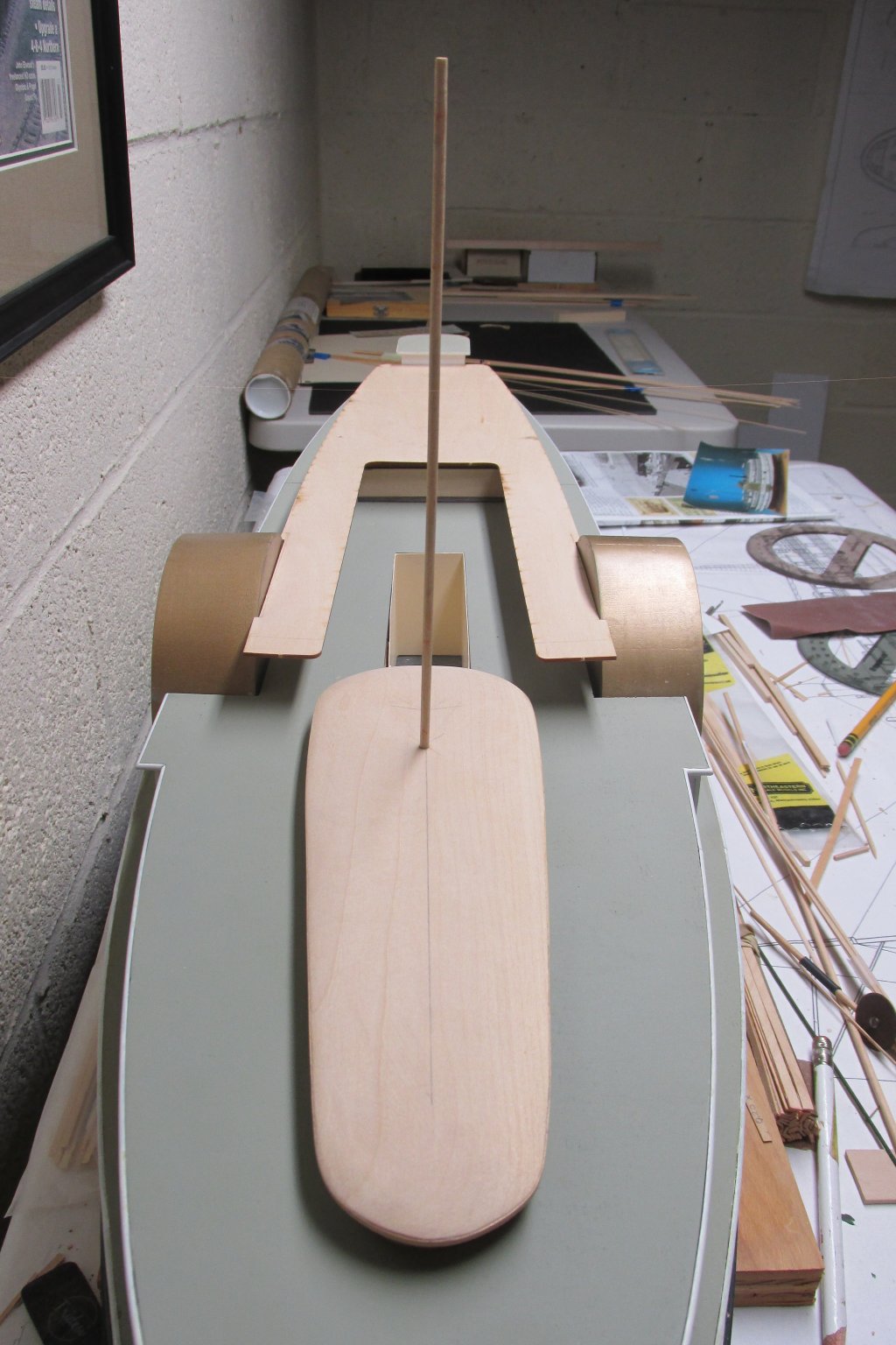
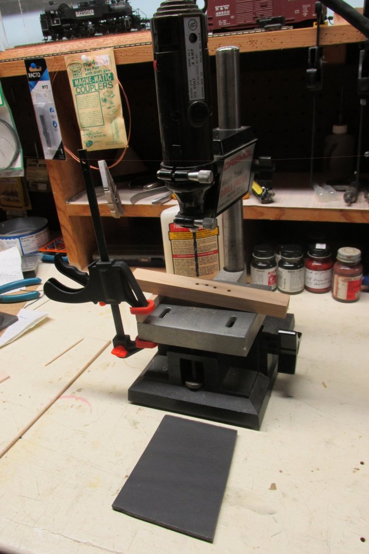
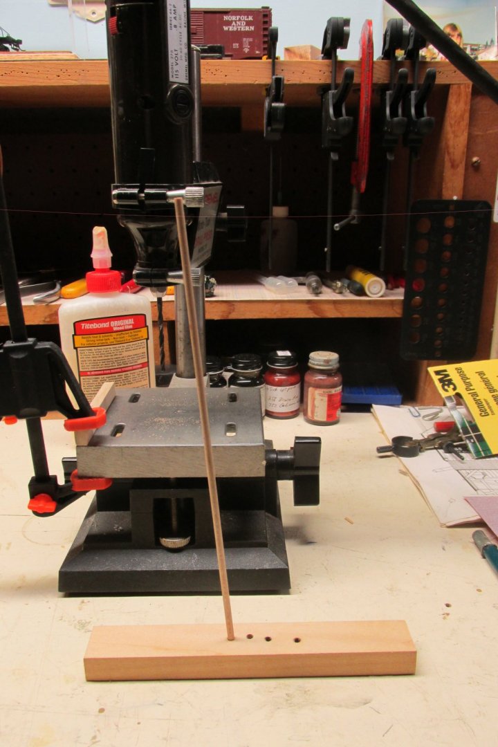
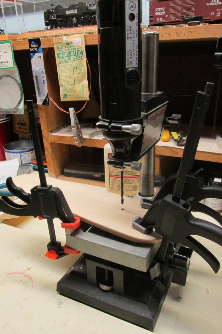
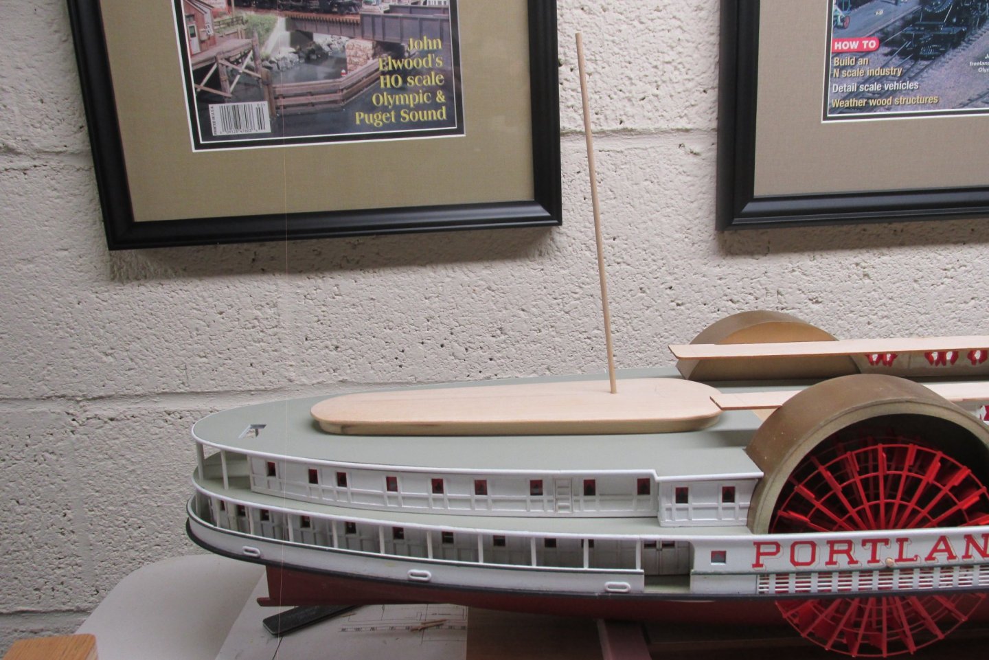
Over the centuries many thousands of ship modelers have had to step many masts. There must be endless ways of doing this. I my case this is a first. As a life long model railroader I have few tools to address this. I do however have a 50 year old Dremmel drill press. I had to step the mast atop the skylight at 90 degrees to the deck and raked back at 5 degrees. I first cut a piece of black foam core to a 5 degree angle and used it as reference to afix a piece of scrap wood to the drill press base. I slid a piece of scrap under that to get the proper angle. Then held it in place by hand and drilled a few holes until I got it right. Then inserted the 1/8" dowel to determine if my measurements were correct. They apparently were. The next step was a challenge. Took me an hour to clamp the skylight to the base correctly so that the bit wouldn't wander. Had to be correct at first shot. The end result was perfect. The mast lined up exactly with the center line of the ship. John Elwood Stratford, CT

-
Nice to see you back Norm. Very few modelers are apparently interested in the Portland. Will try to post the mast installation this evening. Not sure where I am going from here. Need to install the crew quarters and get the hurricane deck in place. John
-
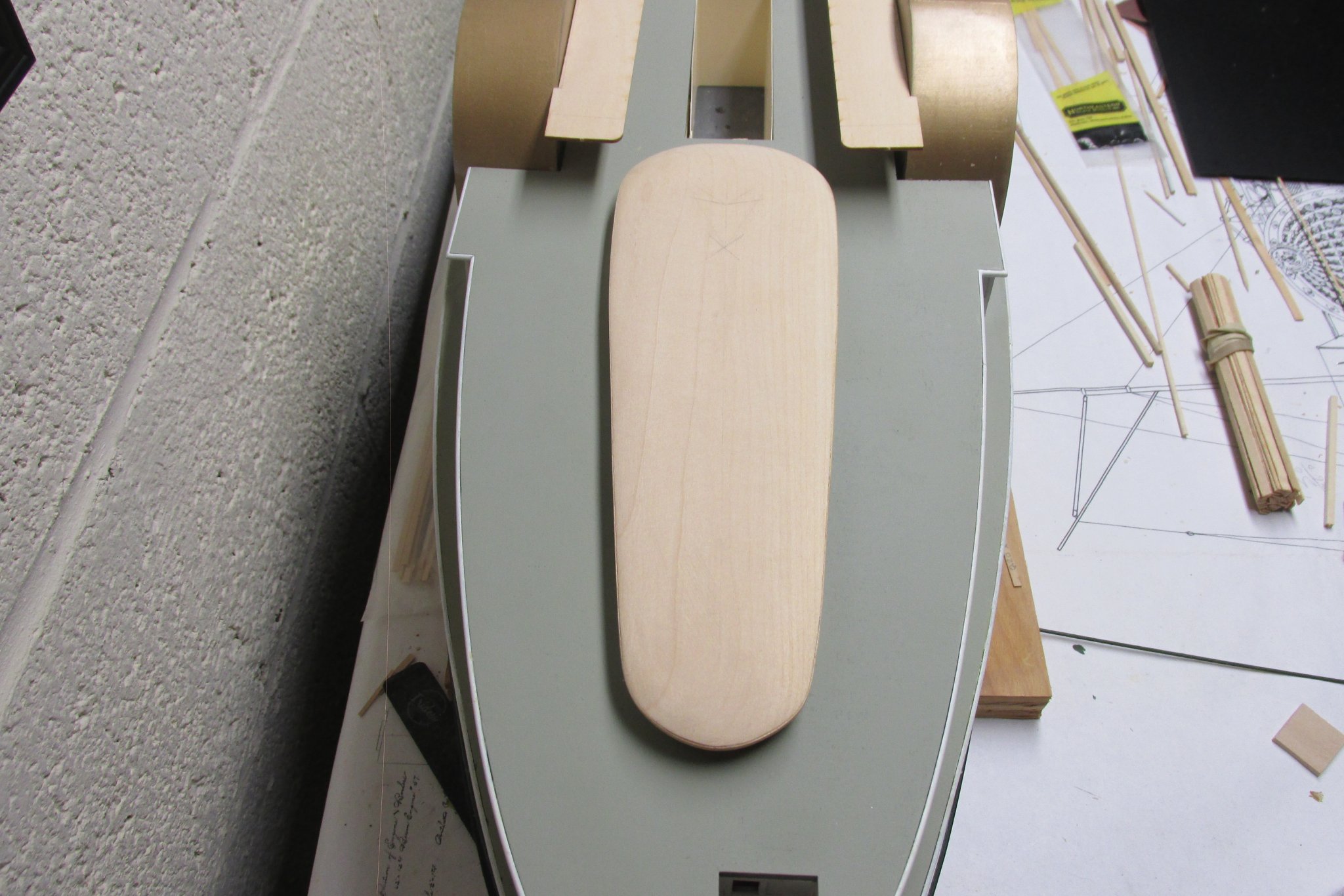
Well, this blasted COVID19 got me back to the Portland again. I decided to tackle the skylight after agonizing about it for some time. We start out with a 1/2 x 3 x 10 inch piece of basswood. I first roughly cut out the top view contour with my bench saw and then finished the outline with my Allwin Disc/Belt Sander. Next you cut a 3/16 high x 1/8 deep rabbet completely around the entire structure. Not having a router, I was able to adjust my bench saw to do the same thing. Cleaned up the curf marks with a sanding stick. Contouring the the roof with gentle curves is not adequately discussed in the instructions. Their instruction manual from the original kit is much more specific. I quote "Draw a centerline on top of the skylight. Measure up 1/16"from the top of the rabbet. Draw a line from the side of the skylight at its widest point (just before the forward curve) to the centerline 1-1/2" from the front edge. Draw another line from the narrowest point of the side (just before the after curve) to the centerline 1-1/4" from the after edge. This double "Y" is the shape of the ridge line. Carve the roof using these lines to the line 1/16" above the rabbet". Page 14 of the new manual give you a sketch of what they are talking about. NOTE: Instead of carving I used 1" wide sanding sticks to create the roof contour. Have yet to figure out how I want to do the windows. My next post will show how I installed the aft mast atop the skylight. John Elwood

-
OK...here's a few for you. Camera shots, unfortunately, show a few years of dust. Oh well. Looking back I probably used Titebond and ACC. John Elwood
.jpg.7f635d8cd89493e9b42645190260582d.jpg)
.jpg.5a9c0bef83adc34fa9780061e17b6f95.jpg)
-
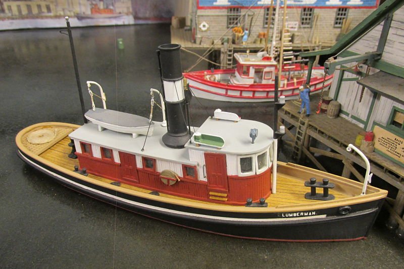
Hi Duanelaker, I've built four of these over the past 40 years. Original list price was $13.00. Shaping the interior of the hull never got easier as I always struggled using a chisel. My latest build, somewhat modified, sits in a river scene on my model railroad. I believe the latest issue of the Taurus has an etched brass pilot and deck house. That sure would make the build much easier and quicker. Will follow you along to see what additional ideas you might come up with. I love these little tugs as they add greatly to a maritime theme if in a diorama. John Elwood
-
Just thought I'd throw this photo in for something different. Perhaps the most photographed scene on my layout. John Elwood

-
Hi there Norm, Thanks for all those photos. I've heard many very positive comments about the museum from fellow modelers who have visited there. From your many photos, I can see why. I have yet to get back to the Portland. My overall health has slipped to a point where the passion to build has diminished considerably. I did finish the trestle however. Although it doesn't show, there are 374 pieces in this model, all cut from sprues. I estimate 70+ hours of work. It is to be installed on a friends Northern Pacific layout over Elwood Gulch. You couldn't pay me to build another one. John Elwood
.jpg.6c49f0029c9260b84115066ecfbfdf3e.jpg)
-
My current project brings me back to my first love of model railroading. The below image shows an HO scale steel trestle and scenery that I built for a client some 15 years ago. I am currently building the same trestle kit (Micro Scale Models) but in a longer (270') and higher (87') version for a close friend. Scenery to be added is yet another story. Quite a departure from the Portland, I'd say. John Elwood
.jpg.e251575aee509deb7f04cedde768ba95.jpg)
-
Have been away from my computer for the past week. Spent the week visiting my daughter and SIL in their summer cottage in Digby, Nova Scotia. Photo was taken in November last year. All last week the Bay of Fundy was extremely calm. Digby is advertised as the World's Scallop Capitol. Bought them fresh off the boat. Thin line in my photo of their photo is due to failed pixel sensor. John Elwood
.jpg.0961e74be5fc62244f186db47078265a.jpg)
-
Before you go any further, take a look at this photo. In particular the paddle box cover. At this point in the build, I couldn't determine where the cover ended. Was it at the main deck or further up just past the saloon deck. No where in the instructions did it tell you to completely cover the box or not. I took a chance and completely covered it down to the main deck as shown in the photo. I guess I did it correctly as the build has gone smoothly since. Out of curiosity, what did you do Dan? You can probably catch a few other little problems, but we'll talk about those later in the build. John Elwood
.jpg.1d1912a0a77a29a76576360bf2704d7a.jpg)
-
Norm, I cleaned it with alcohol and q-tips as best I could. Lousy job at best. Sprayed it without using primer but, looking back, I probably should have done so. Floquil seems to adhere quite well on it's own. And yes, some of the paint has chipped away but easy to touch up.
-
Thanks Mark, I should have known that. Note to Norm, re: MSG question. Lighthouse on CMMS home page yet to be identified. John
-
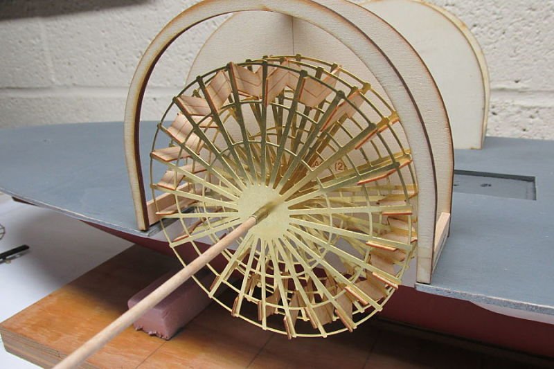
Don't be too concerned about the wrong orientation of the floats. Just make sure the floats are ahead of the spokes in the direction of forward rotation. Once installed only the lower 30 per cent of the wheel will be visible. In the above port side photo, the wheel is still removable. Paddle box cover not yet painted or glued in place. Can't understand why the photo got inserted mid sentence. John Elwood
.jpg.3e252357289a639d148e1fbf04e46df0.jpg)
-
It's been a while since anyone has posted here so I thought I'd bring it back to life. Putting the paddle wheels together is a bit tricky so here's what I did. I cut two lengths of wood approximately 7/16" wide and clamped them between the wheel formers. after spending some time finding three radials where the spokes and rings coincided. Once that was established I added the paddles with CA being careful to orient them properly. Take your time here as the paddles are easily broken. Unfortunately, I couldn't find a way to clean the brass prior to painting. Would suggest washing the oils off your hands prior to working on this assembly. I finished by spray painting two coats of Floquil Santa Fe Red onto each wheel. John Elwood
.jpg.785203d894a0896b171f2c8636ca2367.jpg)
-
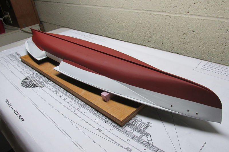
I drew the water line on the bare hull just to get the position of the scribe correct. Being very careful, I removed the hull and painted it completely with primer and white. Then placed it back into the original position. Since it was now positioned exactly as before, I simply drew a new water line onto the newly painted hull. Now I placed the Tamiya tape just above the new pencil line, and checked it several times for accuracy. Then covered the white area above the Tamiya tape with wide blue painters tape. Make sure the WL tape it pressed down securely to prevent bleeding. When you are satisfied, remove the hull and spray the bottom paint in several light coats until you get the desired result. I removed the tape after about 15 minutes of drying time. Yes Norm, that's me. What you saw was the trailer for the one hour video that was for sale several years ago. It was sold out years ago. They had to remove the music that accompanied it due to product infringement. Those interested simply go to you tube and punch in "John Elwood Model Railroader". Here's an example of my work in keeping with the maritime theme. I have many more photos but don't want to interrupt this thread with silly model railroad stuff. John Elwood

-
Here is the final finish on the hull. The photos speak for themselves. I forget what I used for the bottom color. Again, large rattle can. The last photo gives away a secret. Yes, I am also a model railroader, have been for more than 40 years. The two on the left display cover articles that I had in Model Railroader magazine and Railroad Model Craftsman more than a decade ago. The layout itself has more than twelve feet of maritime scenes. John Elwood
_opt.jpg.b44eeaed1435863380051f89fde03c6d.jpg)
.jpg.b85a3a3817ba927ef785c461a822f628.jpg)
-
Here I must digress. Before putting any paint on the hull, I established the water line. As shown in the photo I used (borrowed) a water line scribe available from Micro-Mark. The picture looks confusing as I used a large wall mirror laid flat as a base for the scribe. This enabled me to run the scribe completely around the hull with no faults. Using the plans, I marked where the WL met the bow and stern and placed a small pencil mark. Then spent considerable time getting the hull positioned fore and aft and abeam to align with the scribe. With this all established, I drew a complete WL on the hull as shown. Since I have yet to paint the hull, this allowed me to correct any errors. I then removed the hull and primed it before painting it Rust-Oleum Ultra Cover Semi-Gloss White. When completely dry, I then placed the completely painted hull precisely back next to the scribe. Having previously established the correct height of the scribe, I simply drew the new WL without any errors. That's all for now.
_opt.jpg.1615a5ecafcd52de95d56a1d5f0b7142.jpg)
-
Norm, just got back from a 5 day stay in the hospital. Caught an Ecoli bacteria in my blood stream just in time. Hard to believe you are struggling so much with the decks. From the beginning I struggled with the centerlines. Apparently the laser cut decks are not all that exact. I would suggest you fit them in place as the build proceeds instead of trying to screw align them all at once. You will have more reference marks to guide you. Above all, finish painting the bottom, including water line and sponsons, prior to addressing the upper cabins. Also build the paddle boxes. They will also help you in your alignment with the decks. Temporarily mount the ship on a simple base so you can turn it around and not have reason to pick it up. My next post will show how I drew the water line, and painted the hull. And yes Dan I used Tamiya tape. Perfect for the job. John
-
Have been following your posts from the beginning Dan. Especially taken by your build of the walking beam. I'm still hesitant to jump into that one. My big hurdle right now is the 18 doors in the officers quarters. I would like to be accurate to the plans but it may be too much for my ongoing anxiety level. I am also scratch building each door to my own design. Nic Damuck said his biggest challenge was the railings. You have taken a novel approach that I would not have considered. I'm a long, long way from that part of the build. Did you use a sharpie to color the rail cap and posts? Looks very exacting. Looking forward to more photos. John
-
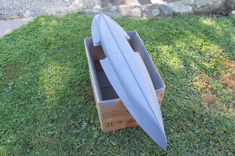
Hull primed with Rust-Oleum flat gray primer.p
.jpg.76386de50fdc18e96f504993843a384c.jpg)
-
Here's the link, I hope. http://www.jrusselljinishiangallery.com/pages/muller-pages/mullerimage-boston-bay-1898.htm
-
Here's my favorite painting of Portland by Bill Muller. I phoned him when I was searching for the deck color of the ship. He had no idea. Go to his thumbnails for some more beautiful paintings of various side wheelers. The two deck area paintings are wonderful. John
-
Sponsons for the Portland. First off, I want to thank Clarence Borgmeyer for suggesting this idea for the sponson build. I first cut the sponson profiles from plan Sheets 1 & 3. Then traced them onto manila folder paper and cut them out. Traced the outlines of these onto the respective hull sides and bottom of main deck. Here was a major problem. As you can see, the three frames are too long for the application. Did away with frames altogether. Here is where I established the shape of the one piece cover to come. Taking the two manila cutouts, I over lapped them and positioned them against the sponson outlines. Then taped the two pieces together and then to the hull to check the fit. If you look closely you can see that there are two pieces forming this shape. th Then I placed the cutouts onto a sheet of 3/32" basswood and cut out the new sponson covers. Glued them in place with Titebond. The "bullnose" ends were shaped with a belt/disc sander. Use the paper forms to draw the outline on the square blocks. Carved a 3/32" notch into the bullnose flat end and slid it under the basswood. Very little sanding and filler needed. I'm quite happy with the results. John Elwood
.jpg.d88783c38ee9e64a573932fcbe2eec7a.jpg)
.jpg.8de99bbb6247dd888c0c778939e88f0f.jpg)
.jpg.c05e63db251af02725cd96b0d0bd30e5.jpg)
.jpg.864759fd430cecb1a3733a44369deed3.jpg)
.jpg.de99fd8559c44703e4b983887d34d1ae.jpg)