KeithAug
-
Posts
3,247 -
Joined
-
Last visited
Content Type
Profiles
Forums
Gallery
Events
Everything posted by KeithAug
-
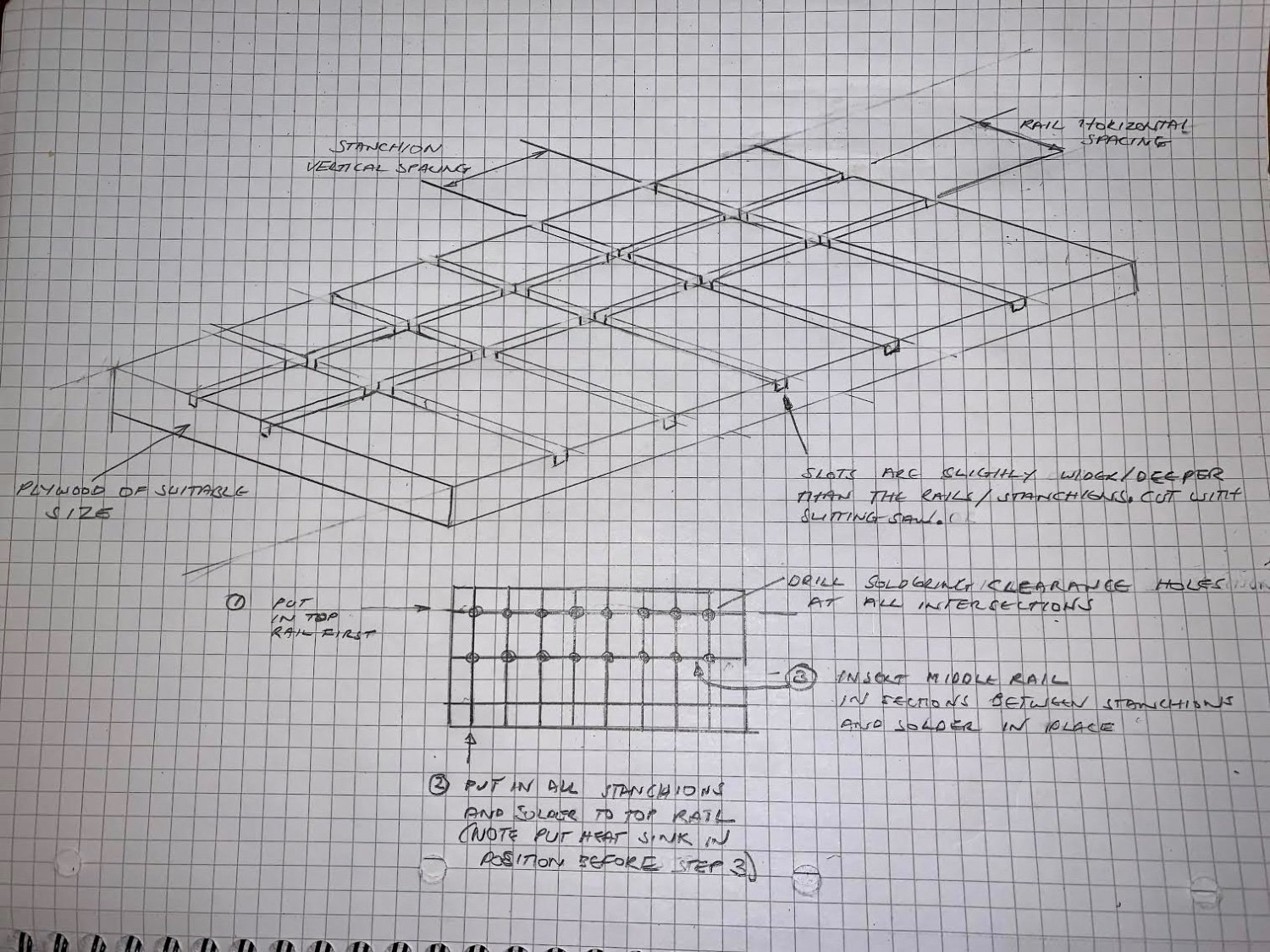
 Brian - I would tend to make a simple plywood jig for this type of operation as follows:- The slots in the plywood are most easily made with a slitting saw on a small table saw - e.g. Byrnes. If the top / middle rails and stanchions are of different diameters use different slot widths. Drilling holes at all the intersections provides clearance for access by the soldering iron tip. The 1, 2, 3 sequence probably makes most sense as continuous runs of the top rail and stanchions will give the best visual effect. The grid of slots accurately controls the position (uniformity) of the finished guard rail. I hope this makes sense? Let me know if it doesn't. Feel free to ignore it if you find a better solution.
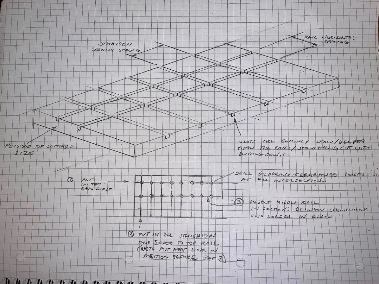
-
Yep Eric - he sold both of us down the river. I better put some extra shifts in.
-
That is hell of an extensive update Brian - and all those laser cut pieces are making me jealous. As for the rails, is styrene going to be durable enough? Presumably if she is going into a case it will be OK. The dusting could be problematic if it is not being cased. I have a way of getting the brass option very regular if you are not wedded to the styrene option. Let me know if you are interested.
-
Thank you Gary. I think you are correct re the motor type because there are no obvious bush access points.
-
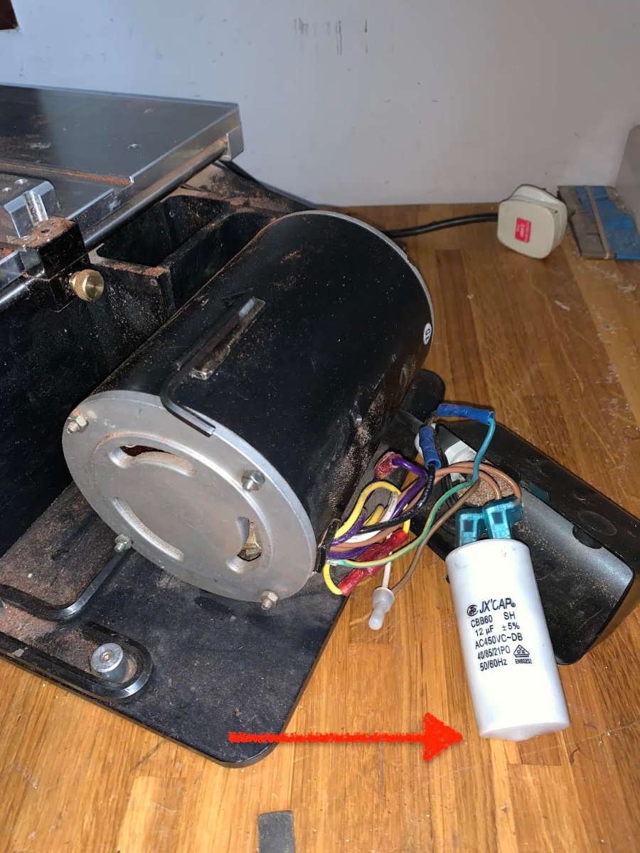
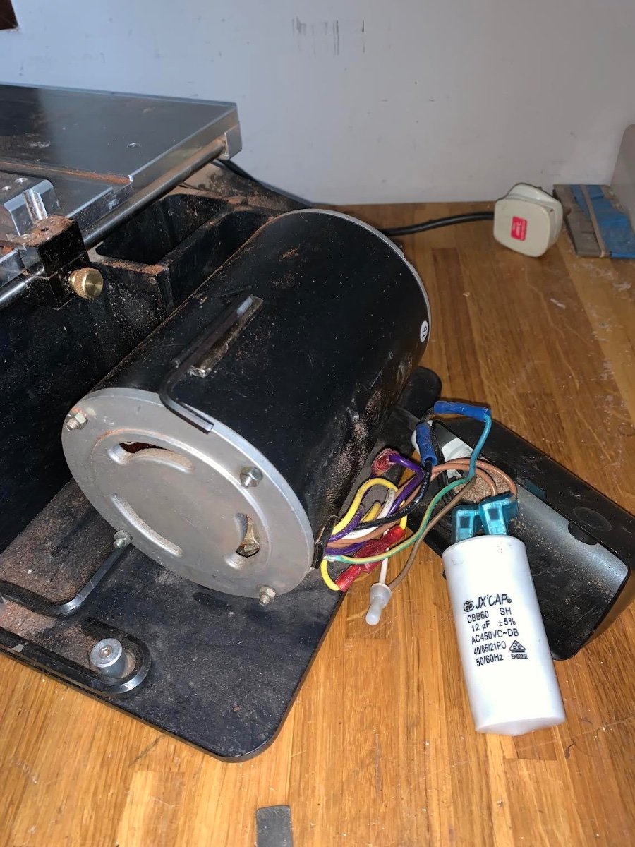
Yes. But I think its the CAP - With age its bottom seems to have sagged!

-
Thank you Keith and Gary. I was going to have a productive day in the workshop but it was not to be. My somewhat recently neglected Byrnes saw decided I didn't love it any more so it threw a sulk and after a few hesitant attempts at starting it threw in the towel. If I manually kick over the blade it angrily bursts into life and bites my prodding stick. Ooch! I think I need to buy a new CAP (maybe a bowler). At least I have learned summat (Yorkshire dialect). the 40/85/21 means that its operational range is -40c to 85c and it will withstand 21 days at 95% relative humidity at - 40c. P.S. Note to self - remember not to lick the terminals - it may be less dead than it is pretending to be.

-
I never thought pipes could be so beautiful.
-
Gary Like the others I welcome the shipyards reopening. Your skills don't seem to have suffered from your layoff. The hull planking looks just the job.
-
In principle yes Andy.
-
Wonderful overhead shots Eberhard. She looks magnificent - that is apart from the crews dereliction of duties on the rope work. Have they been on the schnapps?
-
George - it will turn out fine in the end, just keep at it and you will be surprised how many people are impressed by the result. Putty is fine once painted - only you and your readers will know.
-
Having done my silly post I did give it some thought. On the basis that a metal lathe is only a milling machine laying on its side then it of course possible to make the coaming. How you could do it on a wood lathe is a bit more challenging.
-
Eric - I have to agree with Brian - those clamps are enormous. Did you run out of clothes pegs? Deck looking good.
-
Nicely done Hakan. But of course it is much more difficult for those who only own a number 11 scalpel. Now if you only had a lathe you could spend months working out the best way of turning coamings. 😬
-
Druexy - I sort of imagined they would have many uses when first liberated about 10 years ago. They are nice and springy. We could invent a game - The "what rubbish do you have in your modelling draw" game. Nil points Pat.
-
Andy its a fairing guide - so I know when to stop sanding.
-
Andy / Brick - they must have been made in their billions. Now sadly cosigned to that technological scrap heap in the sky. Brick - it's not your age - they date from 1990's. Thank you John.
-
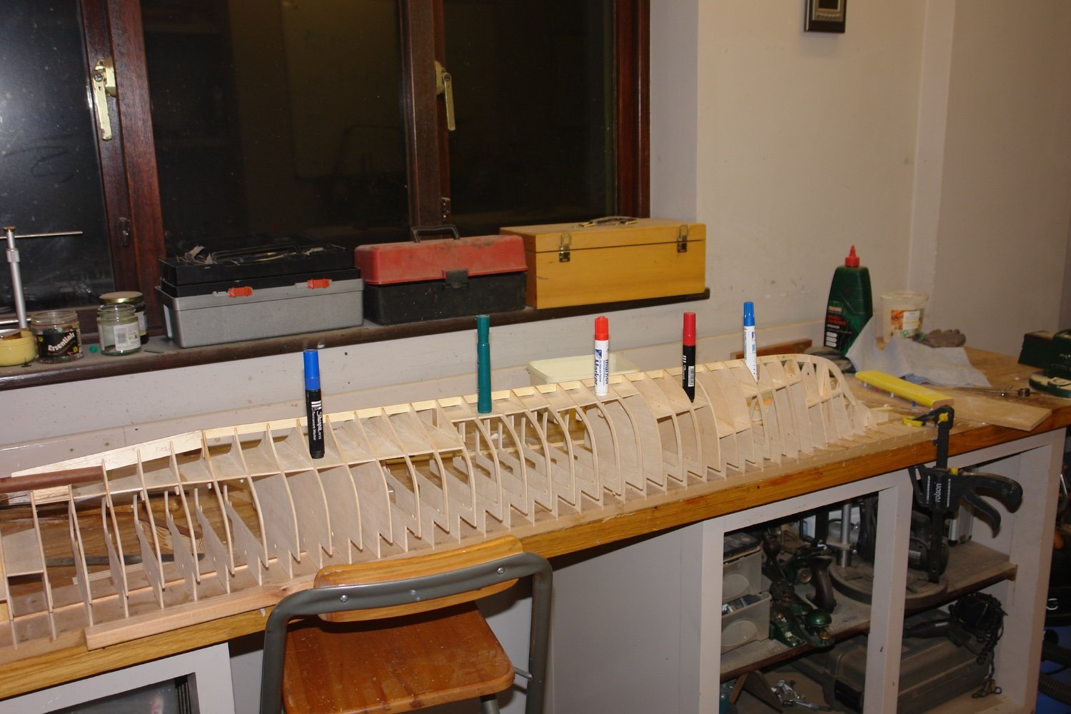
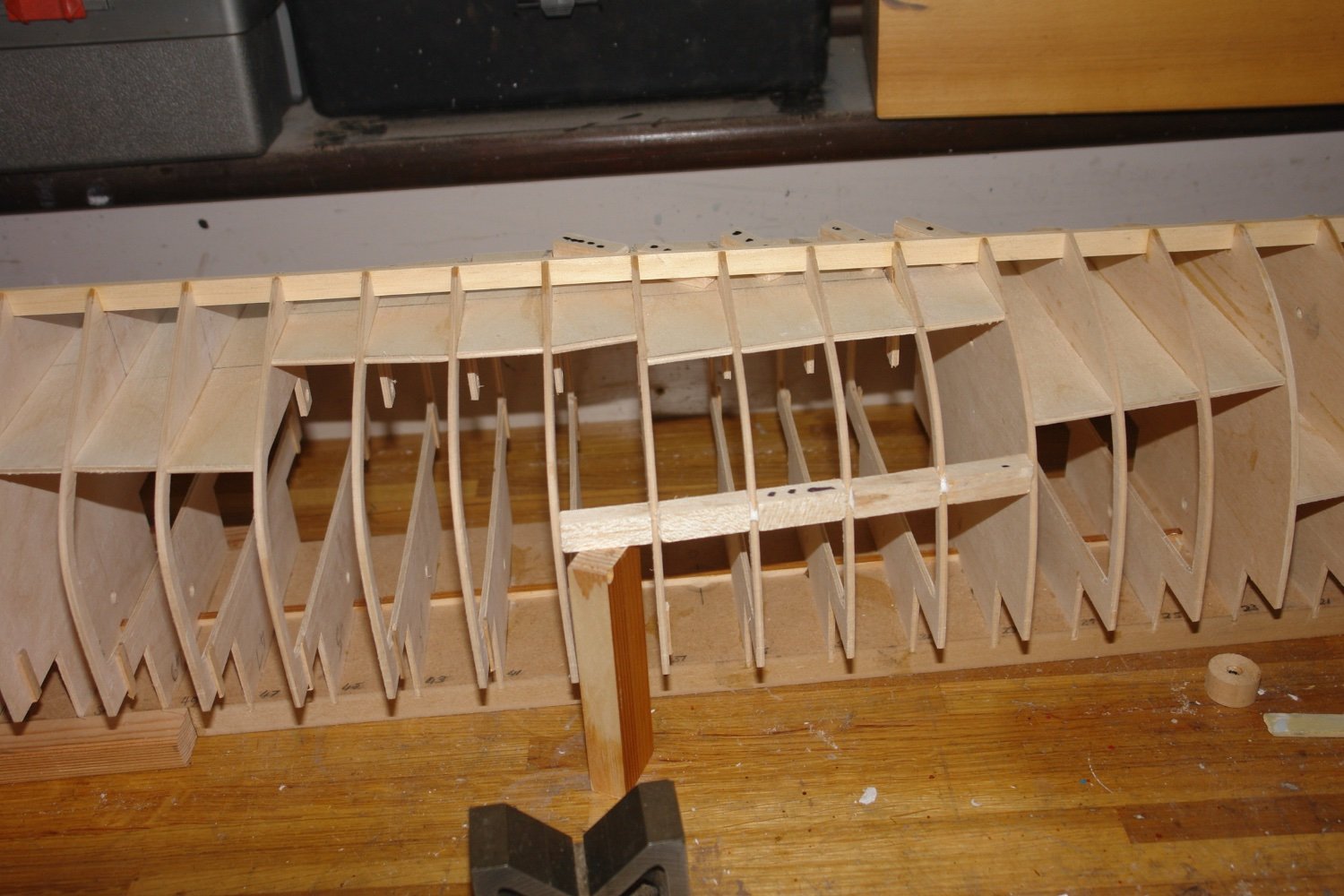
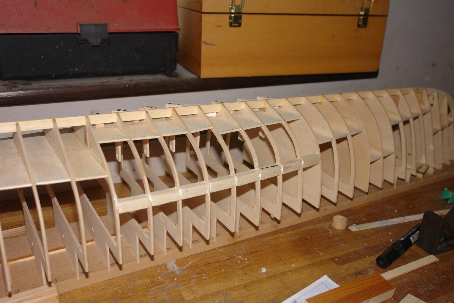
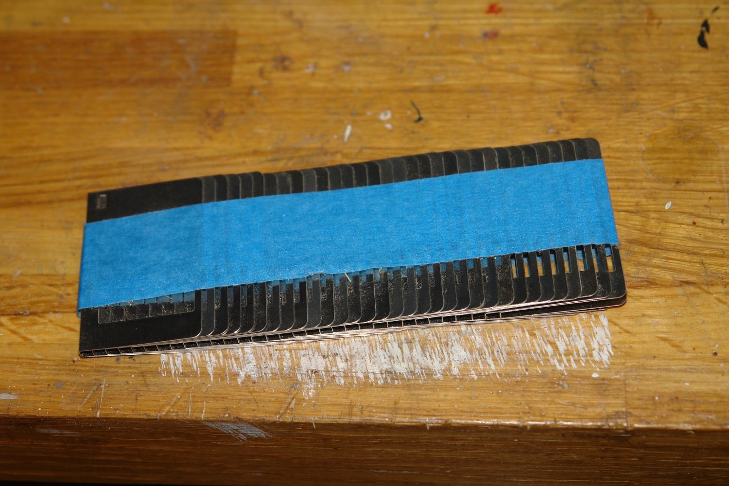
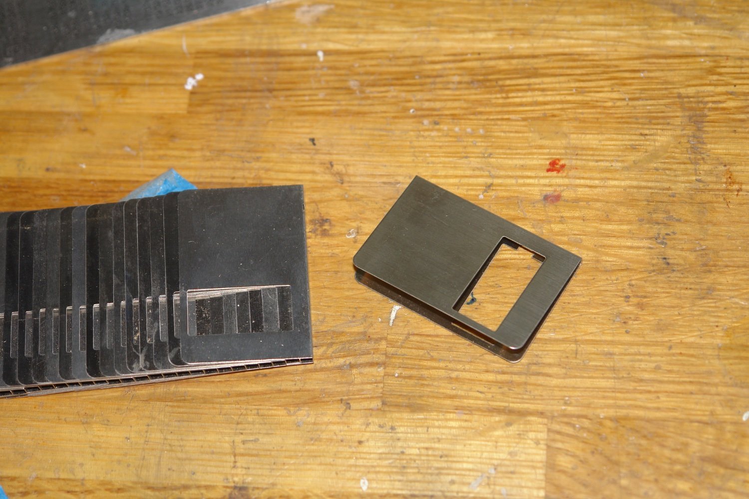
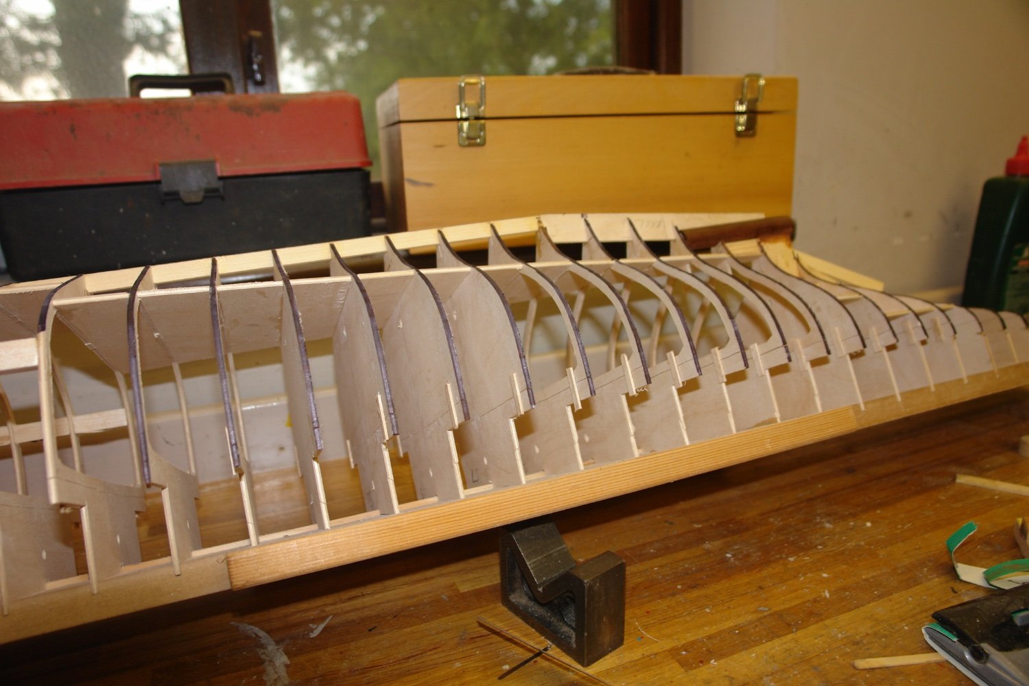
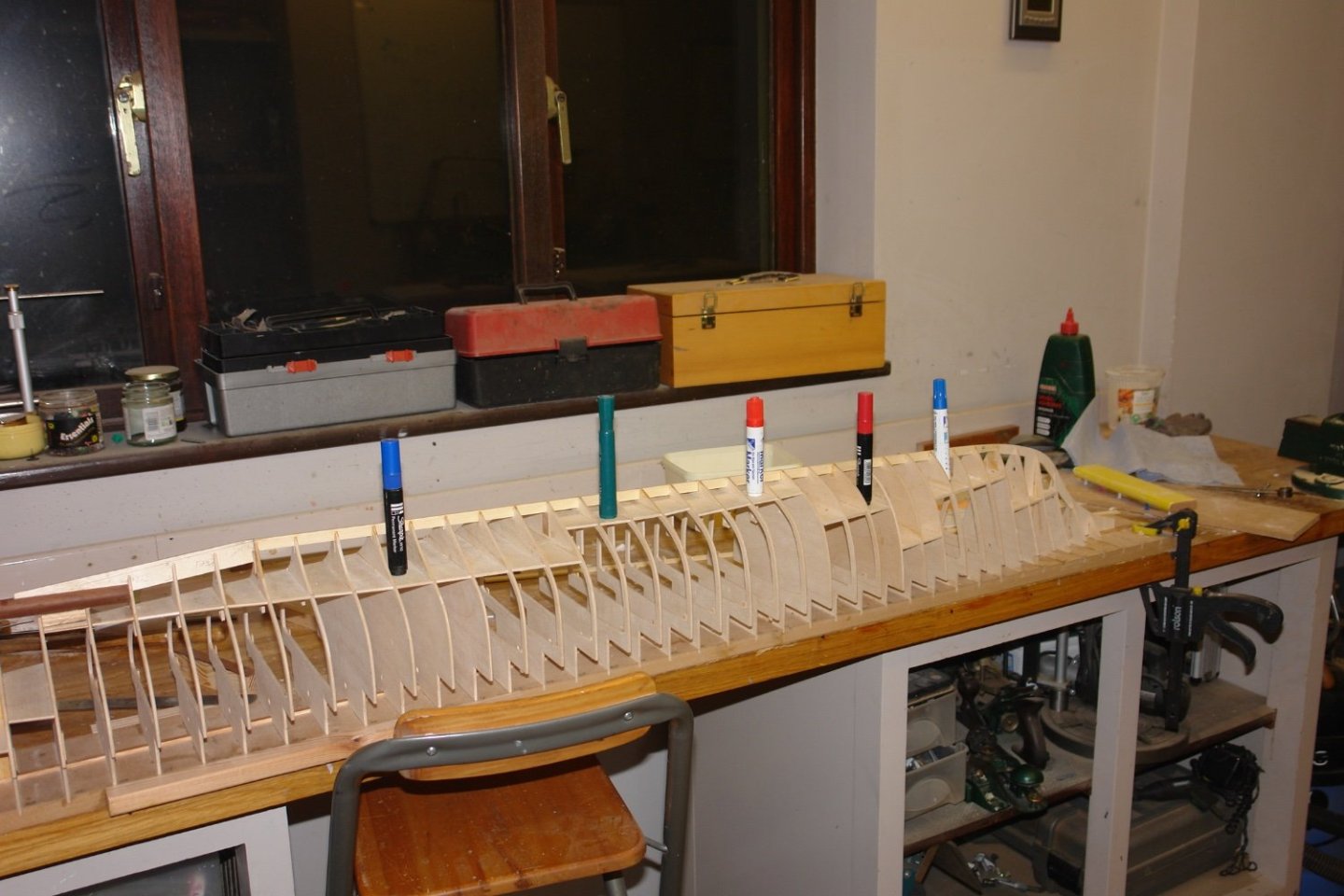
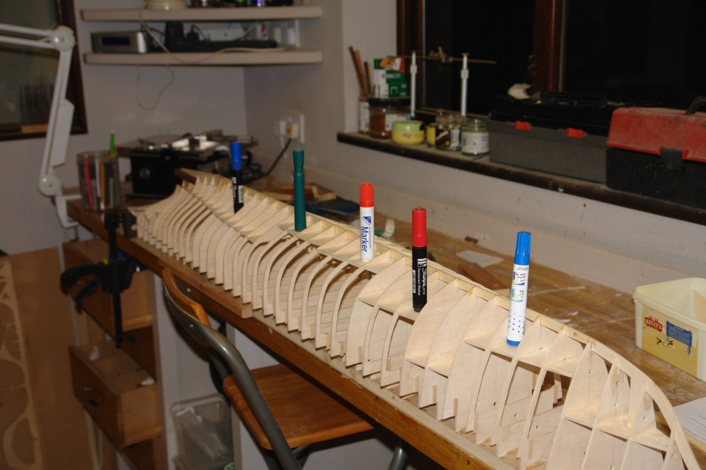
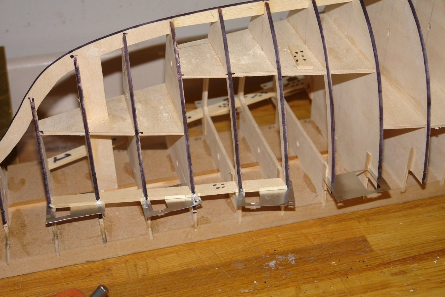
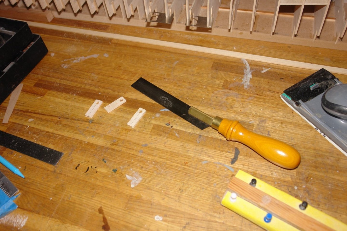
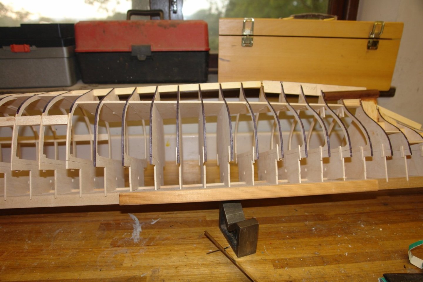
The weather continues to be unseasonably mild with the workshop hovering around 13c. Unfortunately progress has been somewhat disturbed by family commitments. In the following 2 images I have balanced felt tip pens on the floors which are installed at the correct level. The ones without pens are just bracings for the frames. The boiler room floor is just above the keel and hence does little to brace the frames in this area. Additional balsa wood blocks are installed to brace the frames in this area. These will be removed once the planking is suitably advanced. Now for something you will all recognise - a short lived technology no longer with us! I saved these because I thought they would come in handy at some time. I wanted some very thin but stiff shims to insert in the cut lines for the deck. This supported deck edge pieces while the glue dried. I also cut out all the up-stands that were originally used in combination with the alignment rods. I also glued in the prop shaft tube.


-
Beautifully precise work👏
-
Interesting model. I'm looking forward to following.
-
luddite - Lathes and mills just introduce further layers of problem solving opportunities - and flanges can be made out of metal - like the real ones are.😀
-
Fascinating model. I'm looking forward to seeing how it goes.
-
All looking very neat Mark. I like the idea of the rubber bands pulling the planks together.
-
Ian - my view is that planking is an art not a science. My preference is to start at the deck and make my way towards the keel - however hulls can be very different in shape and what works best for one won't necessarily work best for another. My advice would be not to worry too much about all those youtube videos and just make a start. It was easier before the internet because it was just a case of suck and see. The main thing to bear in mind is that planks should bend in their narrow direction and not in their wide direction. You will find that the first plank naturally wants to go on while only bending in its narrow direction (i.e it follows its natural curvature). Your tendency will be to try and force it to follow a different line (like the deck edge). Doing this forces it to bend in the wide direction. If you force it too much the plank will start to twist producing a clinker effect which is undesirable. I could go on at length but my best advice would be to put a few planks on, then post an update and request advice as you go. Your frame is looking nicely made. The planking is going to be quite difficult across the final 4 frames because they change shape quite dramatically.