


KeithAug
-
Posts
3,247 -
Joined
-
Last visited
Content Type
Profiles
Forums
Gallery
Events
Posts posted by KeithAug
-
-
-
Beautiful planking job Mark.
-
-
33 minutes ago, Rick310 said:
I hope there is a buyer in her future.
Hi Rick - yes let us hope she goes to a good home. I fear that she isn't suitable for the usual super yacht brigade.
2 hours ago, BobG said:I just came across your build log, Keith.
Welcome Bob I hope you enjoy the remainder of the build, you may need to patient I am not fast.
- mtaylor and Keith Black
-
 2
2
-
6 hours ago, wefalck said:
but I gather, being 'under water' it will all be painted?
Eberhard - thank you - my current thought is to paint the hull above the waterline to match the original but to varnish below the waterline to show off the mahogany and brass. it is still early days and plans might change depending on how neat the planking is.
2 hours ago, druxey said:The bulldog clip is a nice hack for taper sanding!
Druxey - Thank you ----- and the angle can be changed by moving it in or out from the edge.
And thank you to the Black twins for their unrelenting support.🙂
- Keith Black, mtaylor, Retired guy and 1 other
-
4
-
Excellent progress Nils. I look forward to the next instalment.
- Mirabell61, Jack12477, Canute and 2 others
-
5
-
Thank you Andy and John.
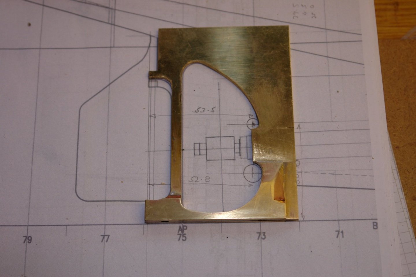
I spent a few hours today completing the rudder (excluding finishes).
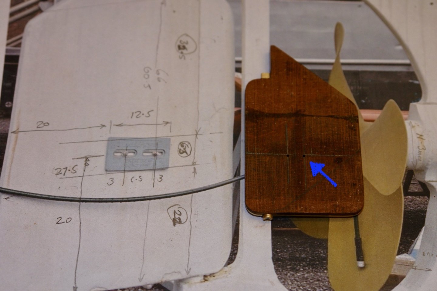
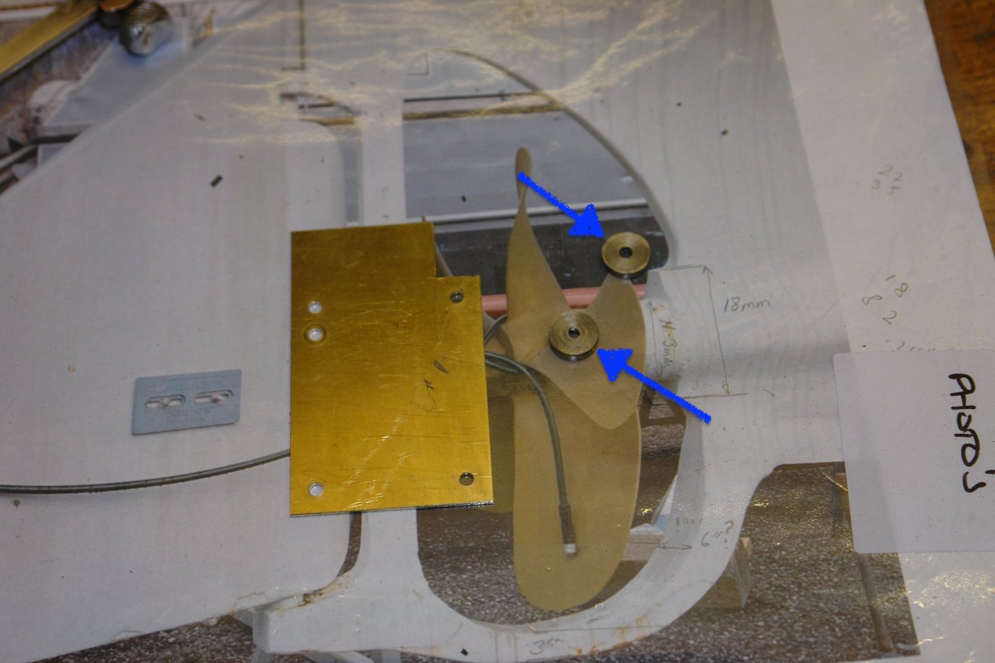
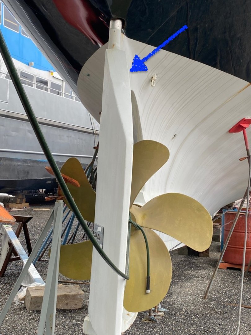
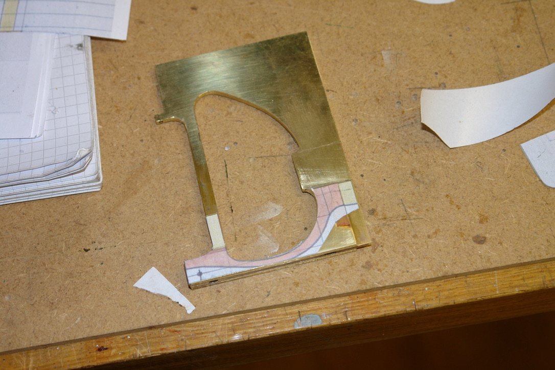
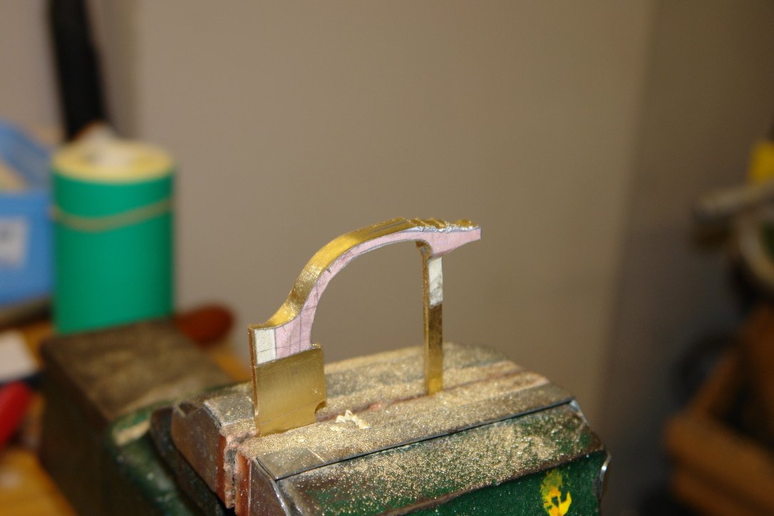
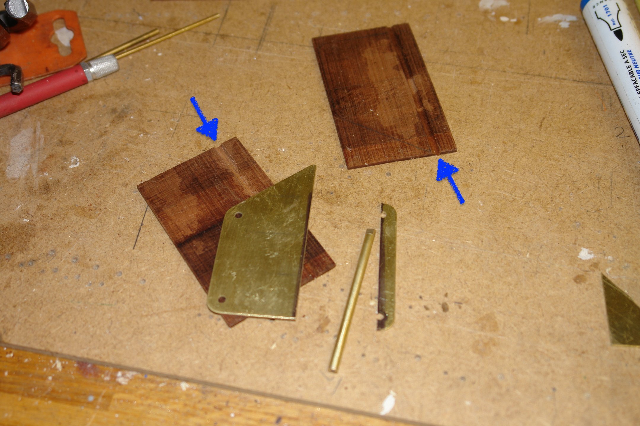
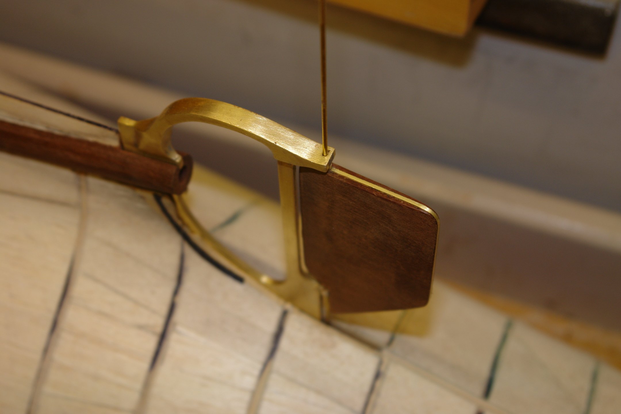
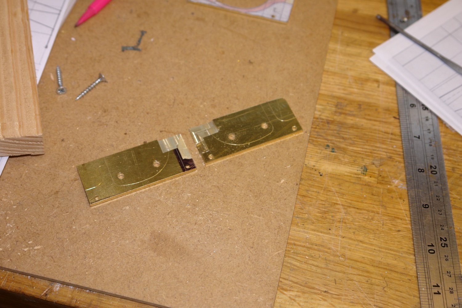
The shaft is 0.16" diameter while the plate is .04" thick. I therefore needed to machine slots in the the cladding 0.08" radius by 0.06" deep. See blue arrows on next photo. I also cut the plate along the line of the shaft removing a .016" wide strip.

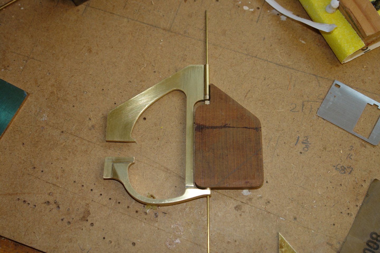
The brass pieces were then assembled on the cladding and glued in place using CA glue.

The other side of the gladding was then glued in place forming a brass sandwich.
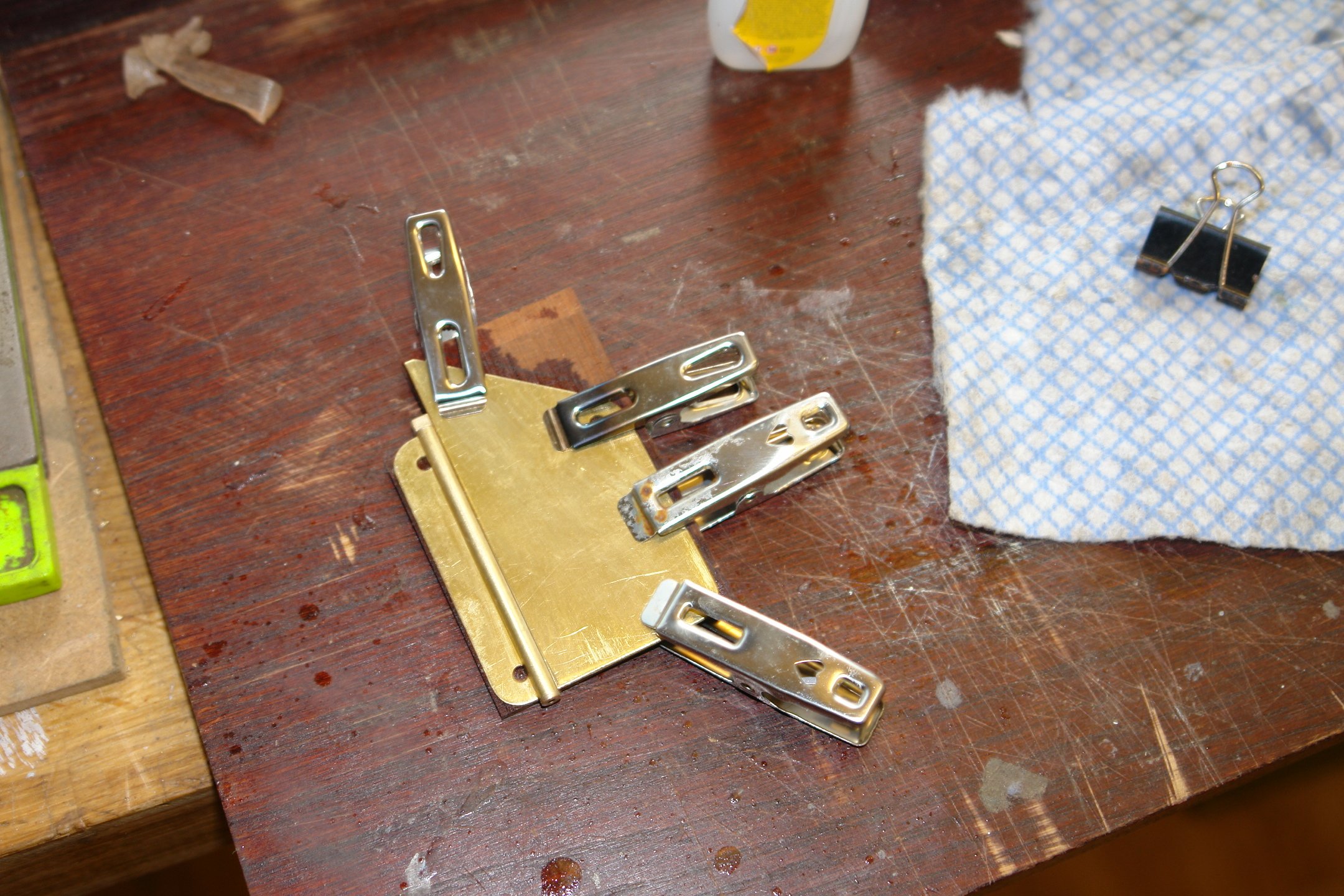
The rudder is fitted with anodes. All the anodes on Cangarda are of the same flat plate type. I drilled the holes for later anode attachment.
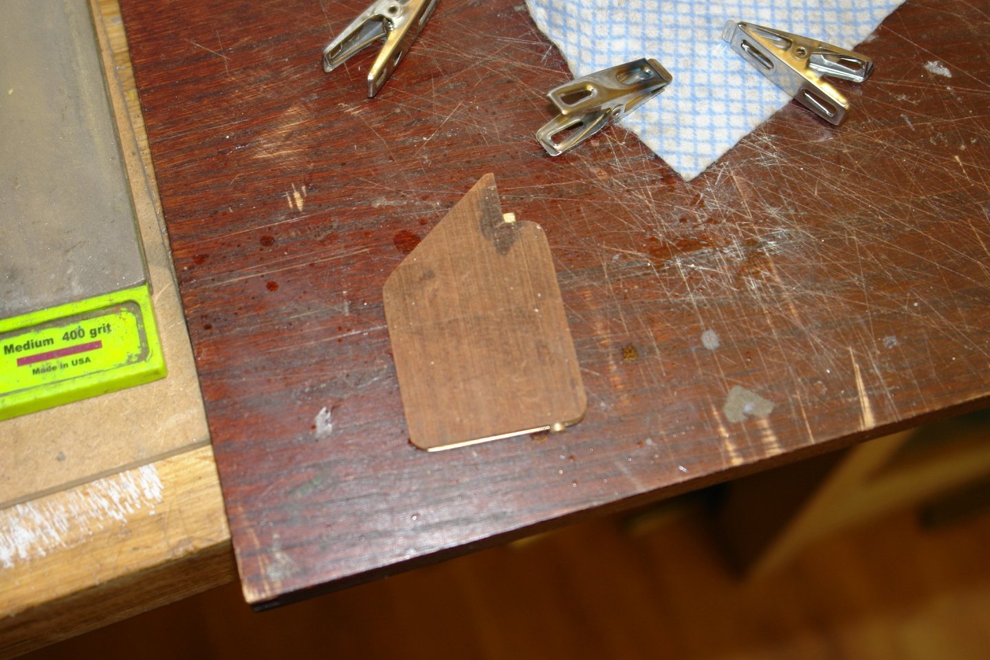
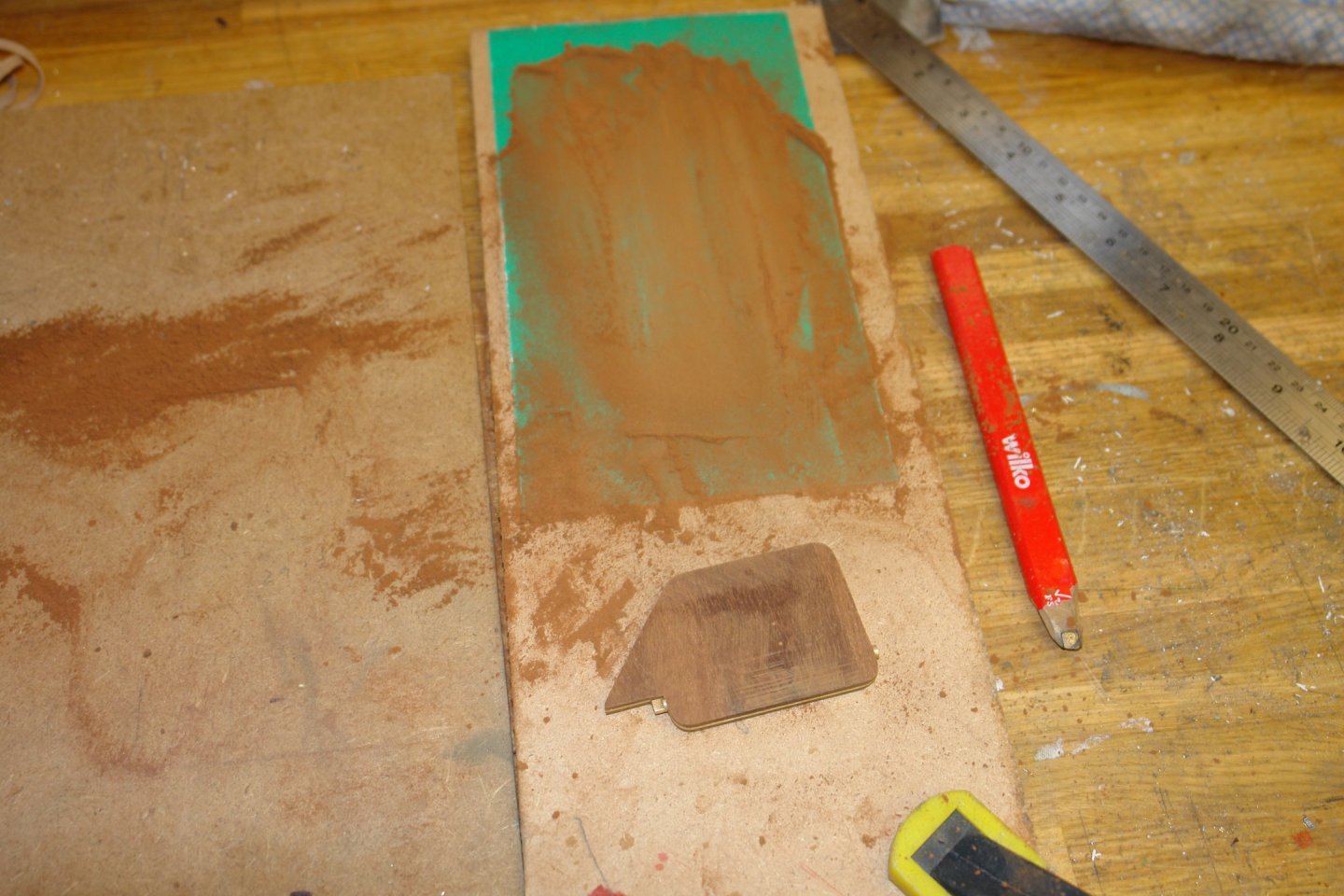
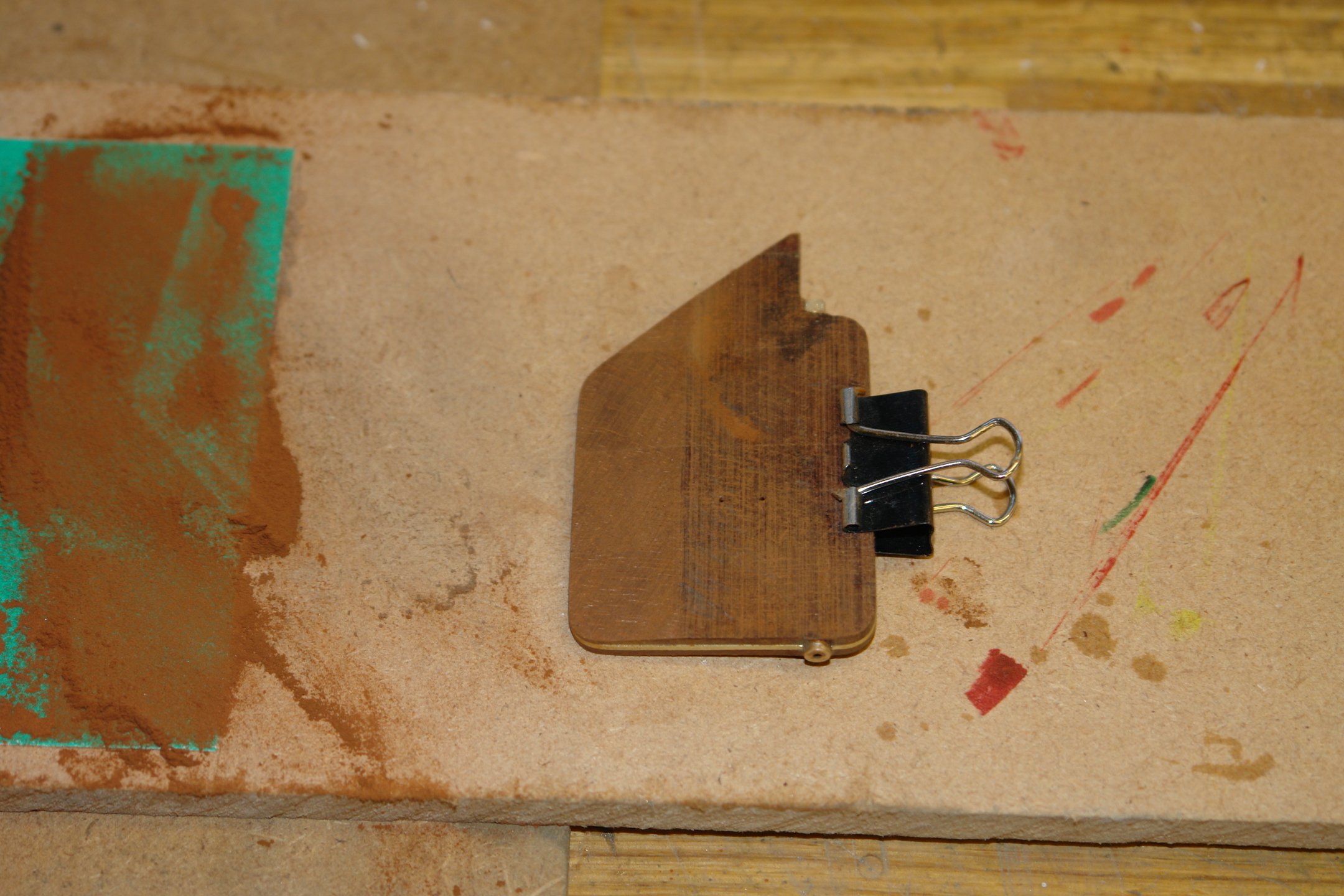
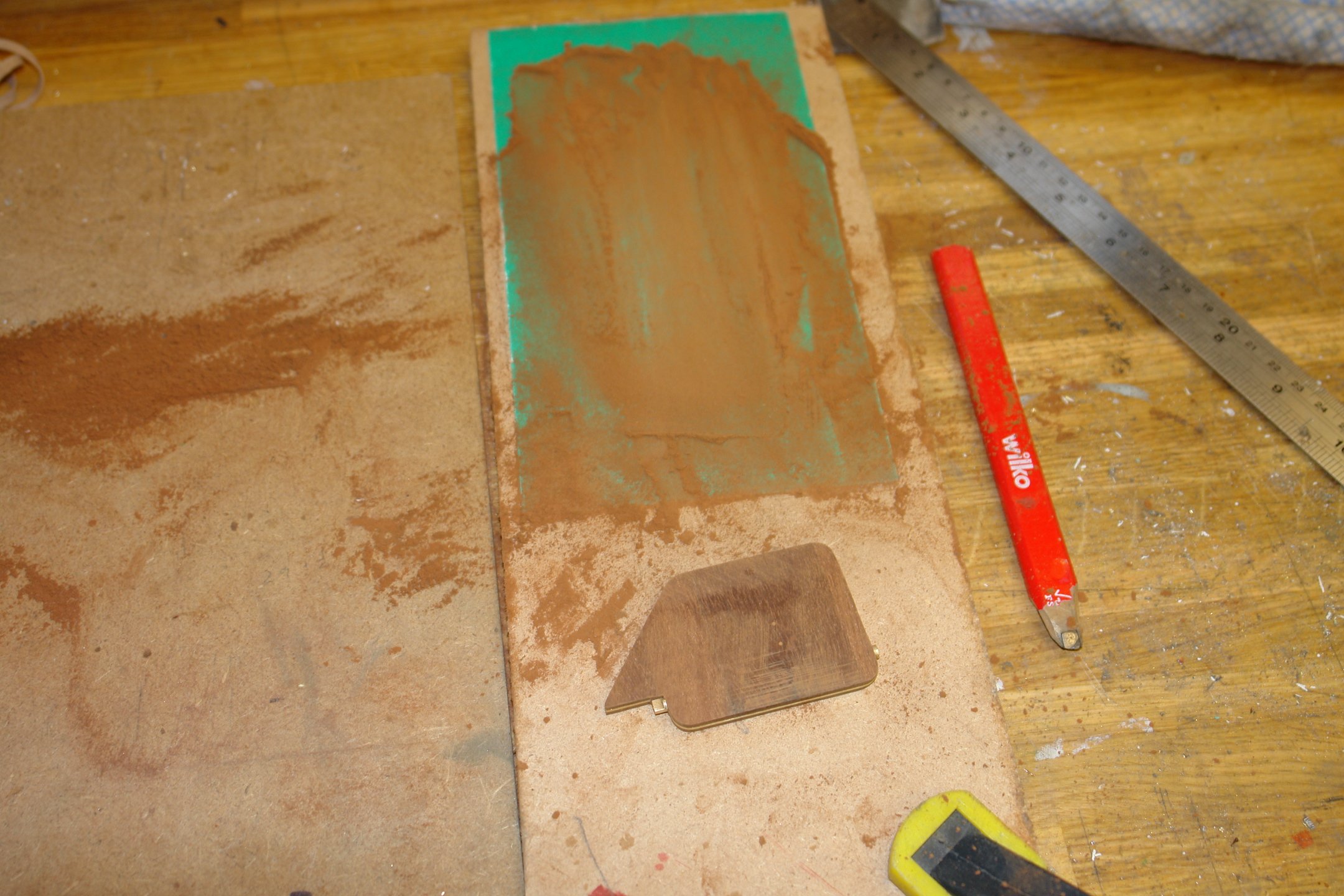
To get the taper sanding of the cladding symmetrical I employed a flat sheet of aluminium oxide paper and a bulldog clip.
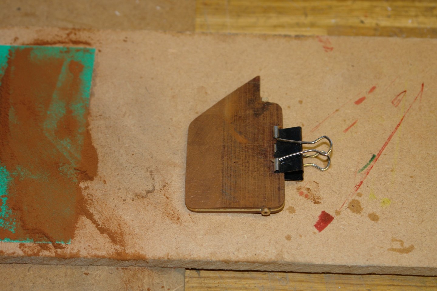
The bulldog clip is holding the front of the rudder clear of the sandpaper and at a constant angle while the taper is sanded. The bulldog clip spring is hard enough to resist the abrasion of the oxide paper. The taper on the front edge of the rudder was formed in a similar manner.


My plan is to get on to the planking next. I expect it to be a long job so if you want to skip it I suggest you rejoin in about 2 months.
-
Thank you Richard and Pat.
On 4/14/2024 at 5:11 PM, FriedClams said:I hope she appreciates how fortunate she is to have such a father.
Gary - She says it is her greatest pleasure to be my forever financial burden. She also says my efforts are earning points which will influence her when choosing the quality of retirement home she will be putting me into when I can no longer look after myself.
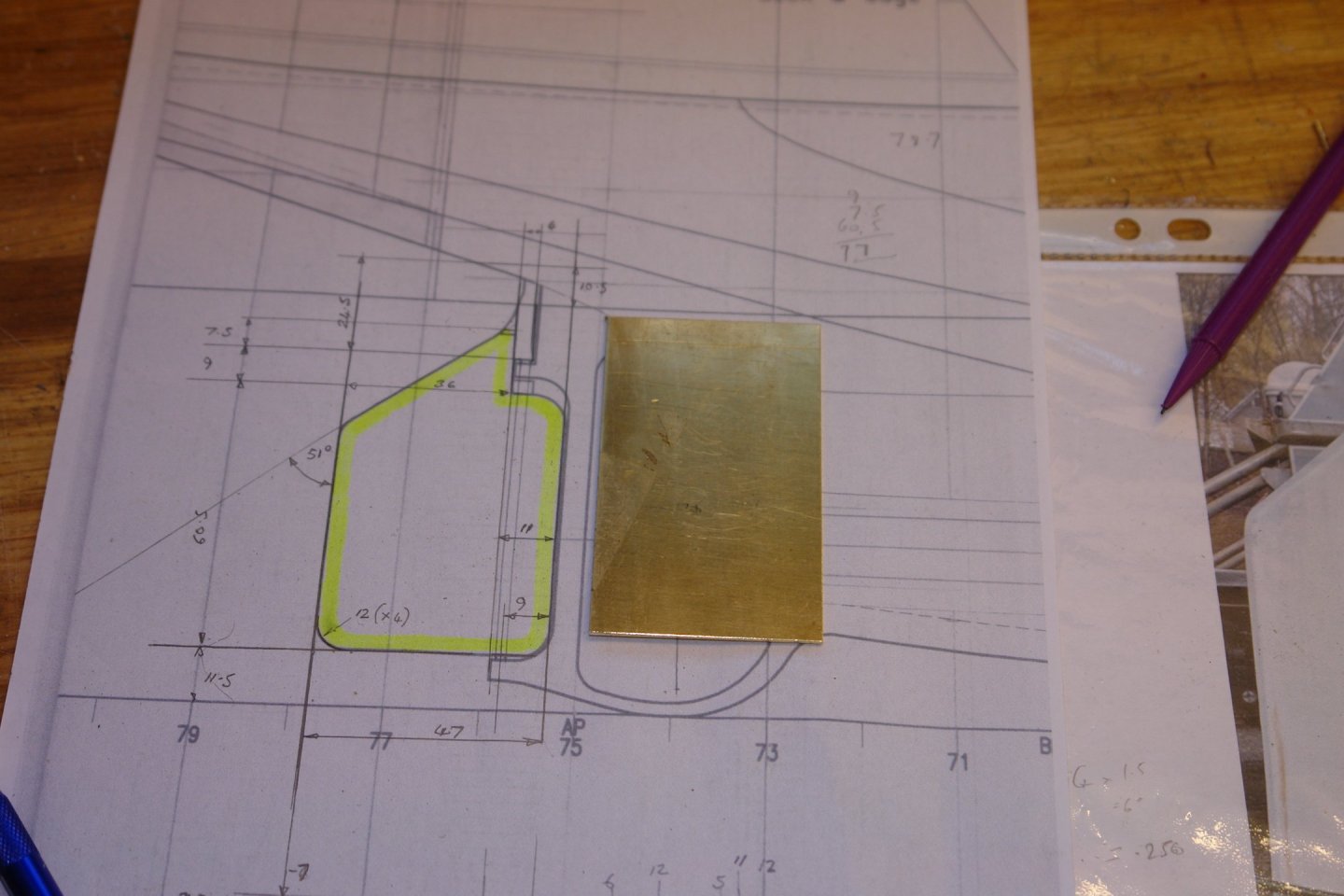
And so on to the rudder.
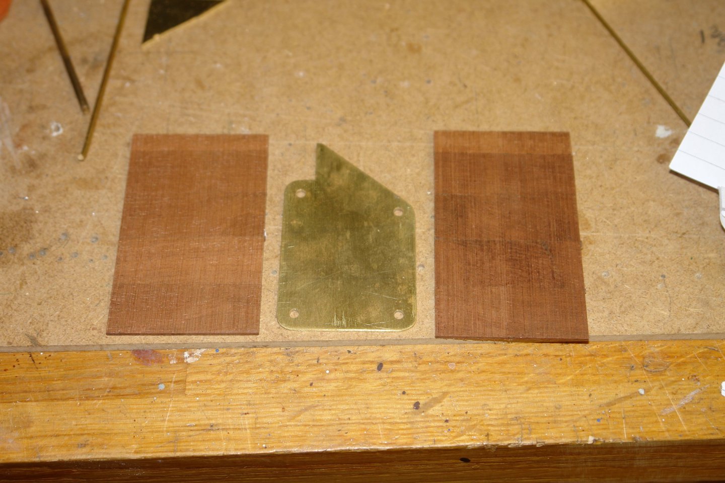
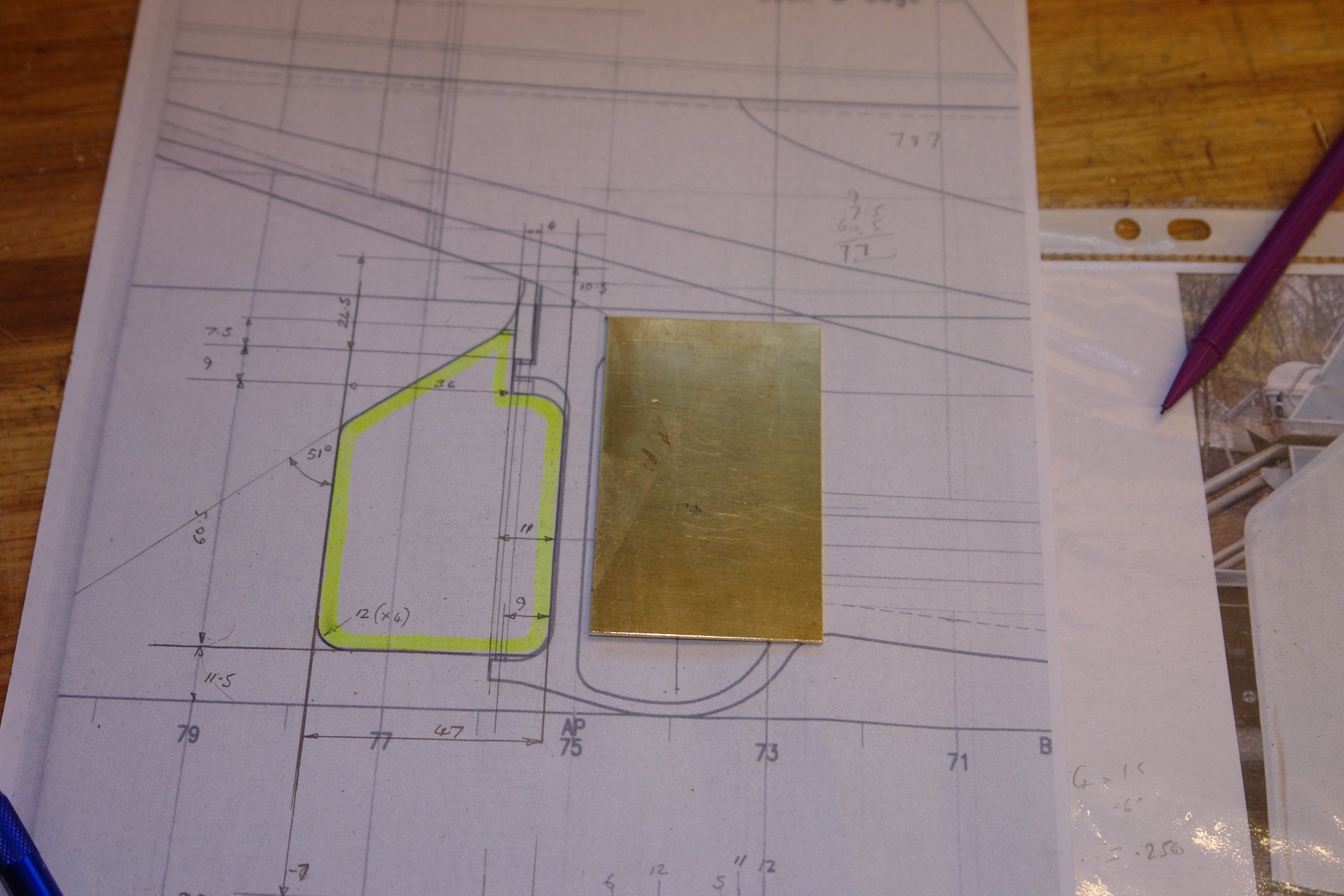
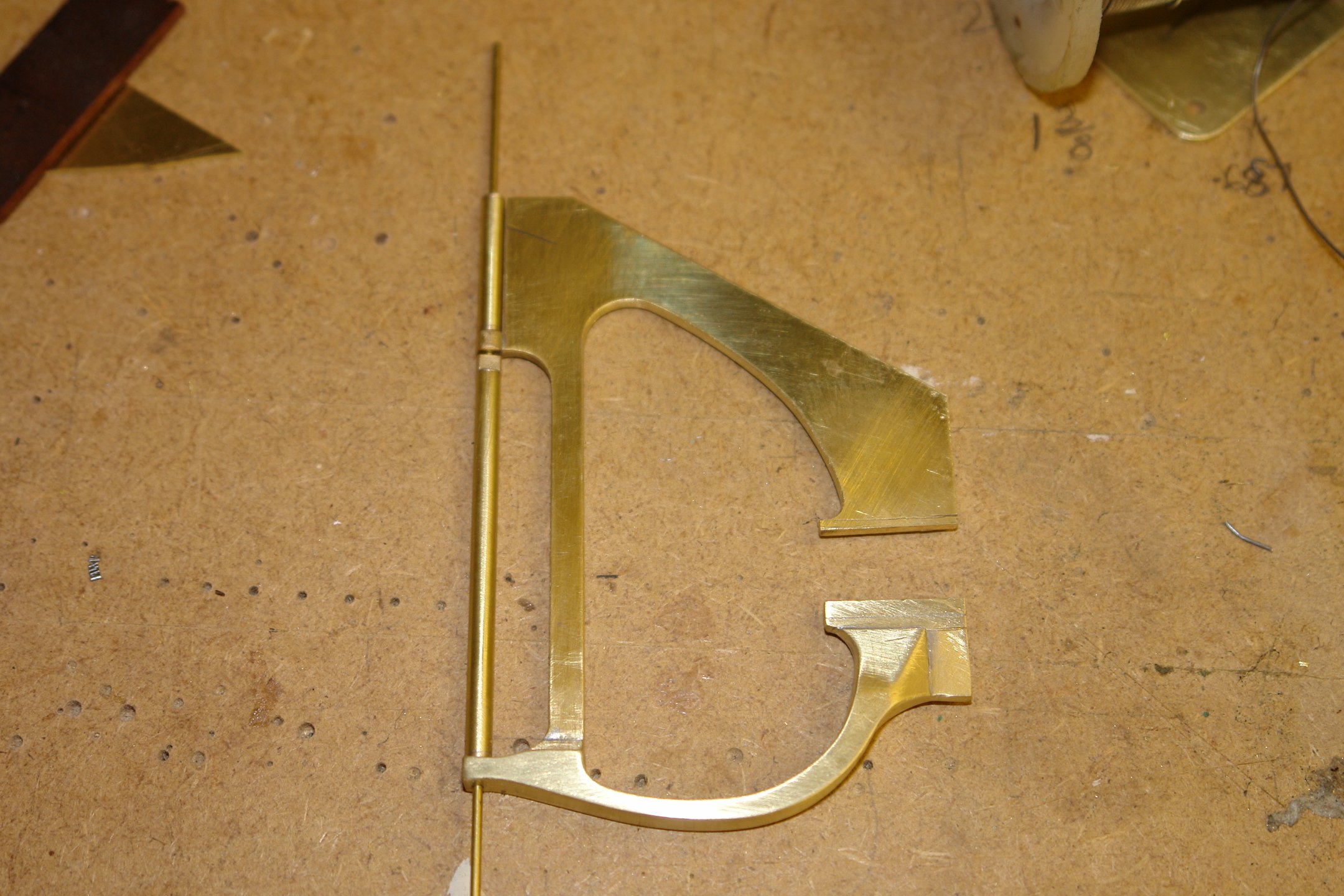
I started with a brass sheet .040" thick.
I drilled a number of holes at the centre of the various edge curves. I also turned up some filing buttons - blue arrows.
I cut away the waste brass and using the buttons I filed the edge curves.


The rudder is profiled / streamlined although the front and rear edges are blunt.
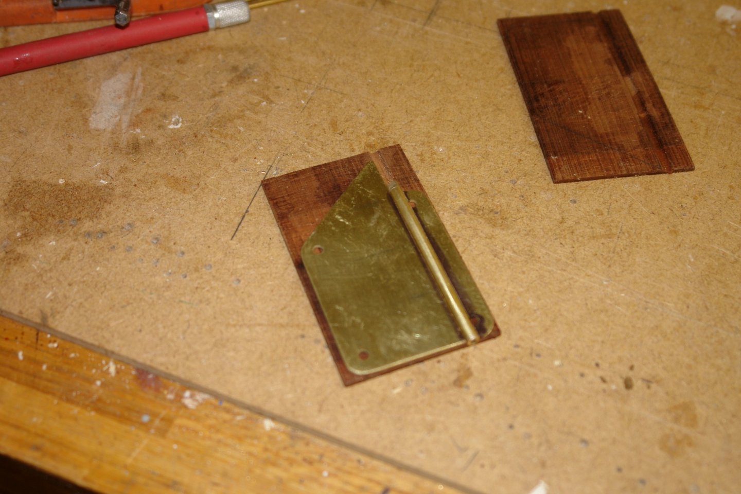
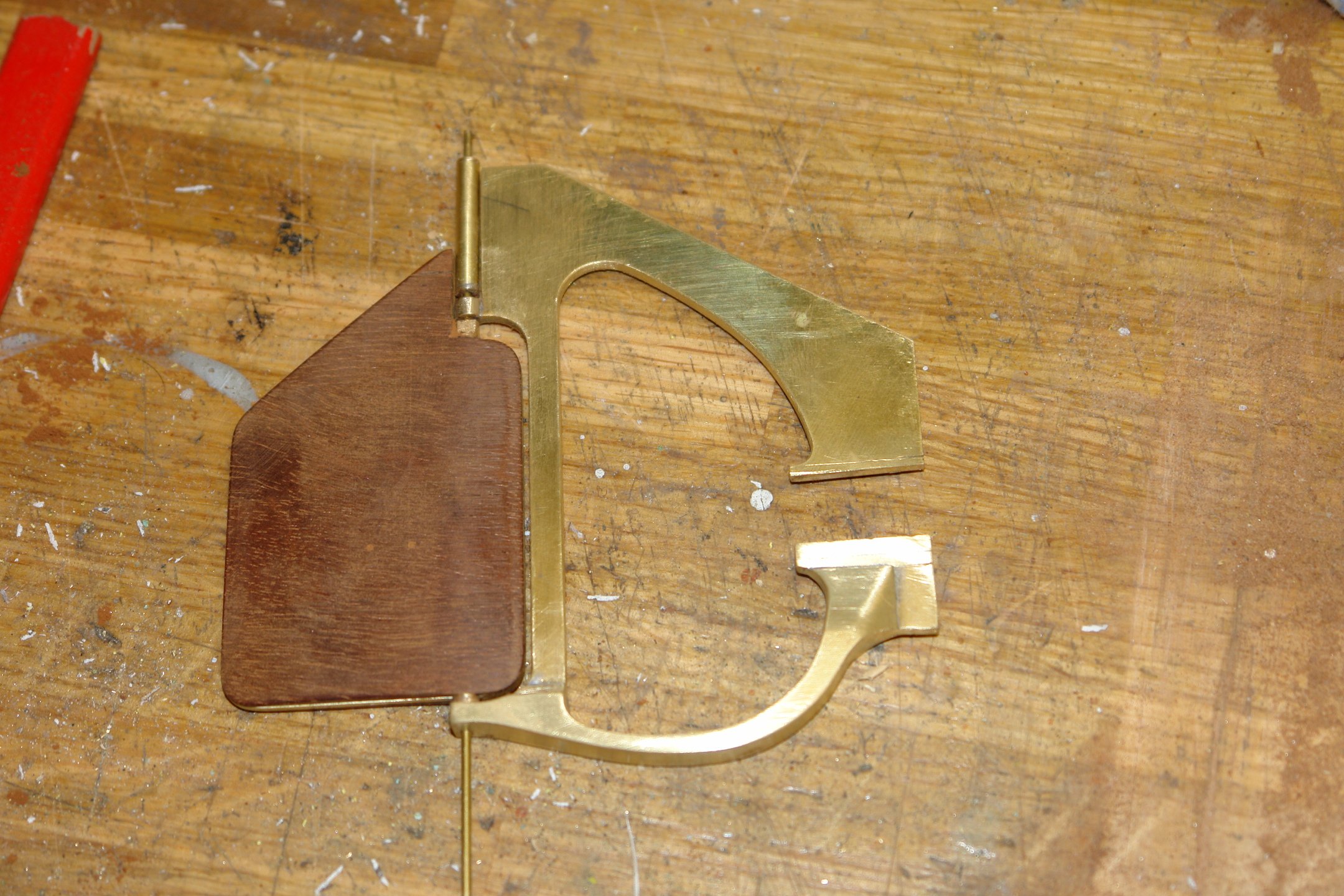
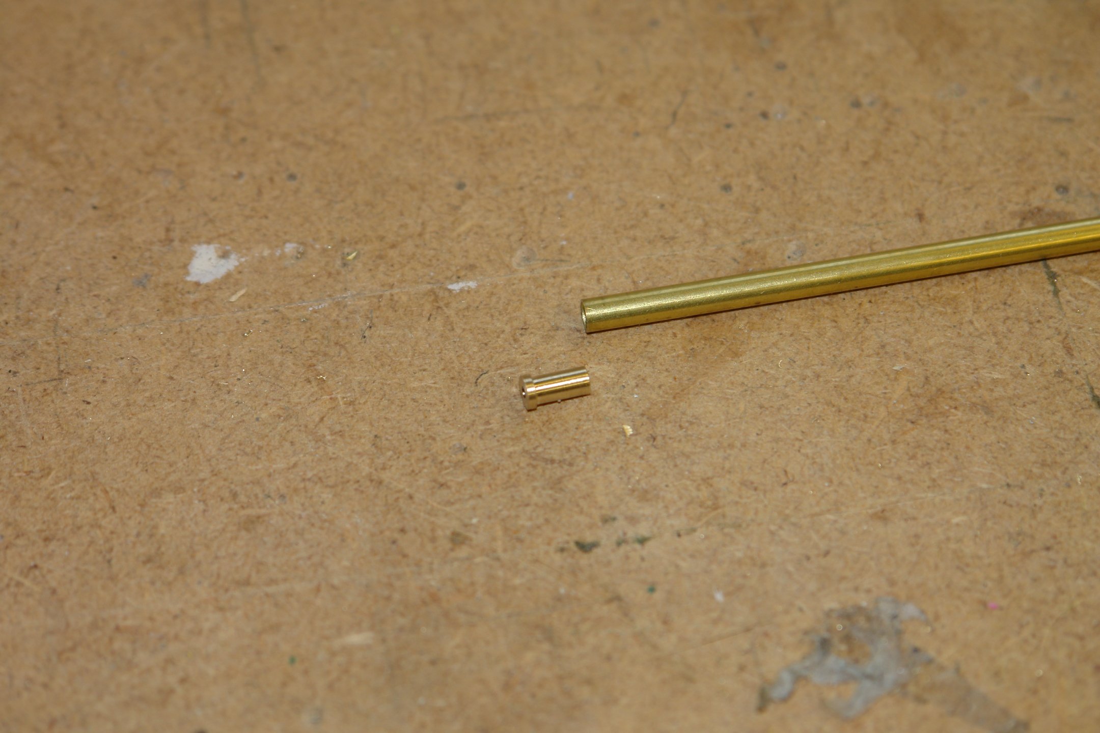
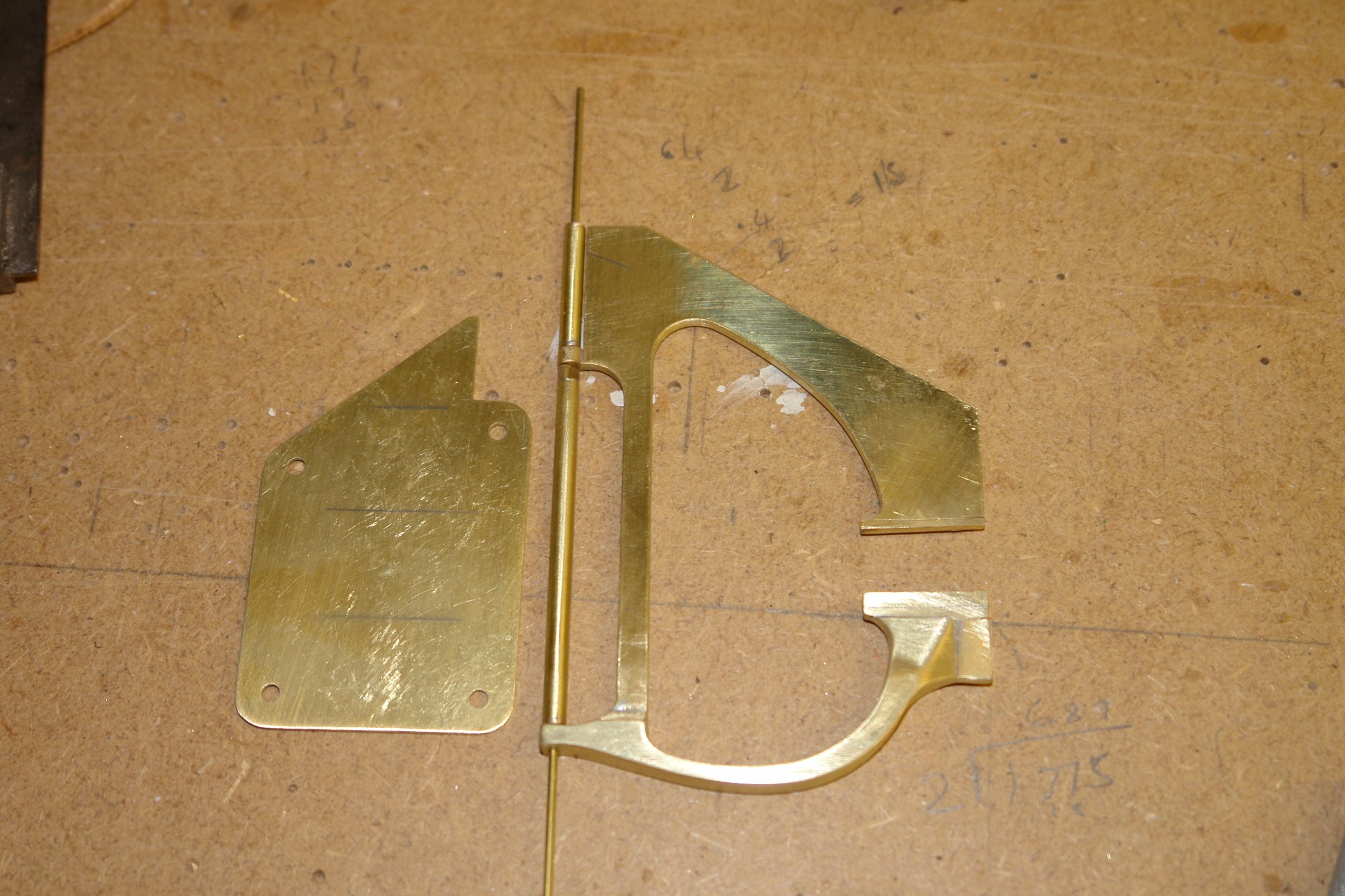
The outer rudder shaft was made from brass tube with bearing ferrules at the upper and lower ends. The ferrules are drilled .040" diameter to take the fixed inner bearing shaft.

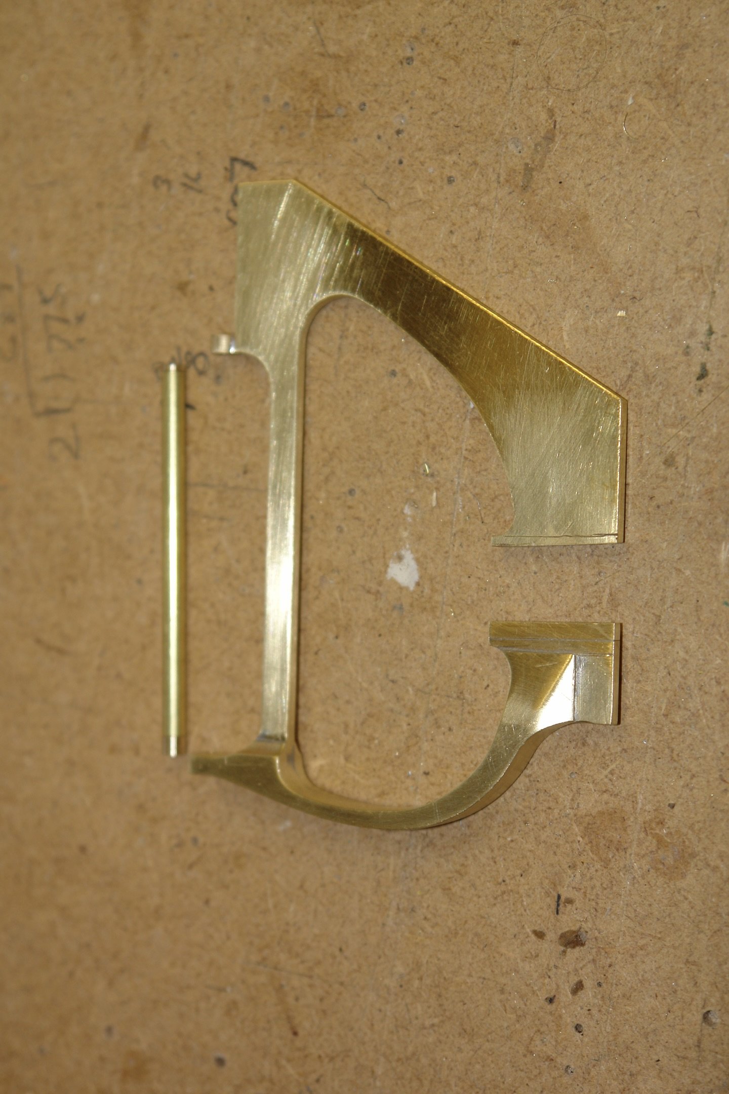
The small upper section shaft was made in a similar way. Below all 3 parts are assembled.

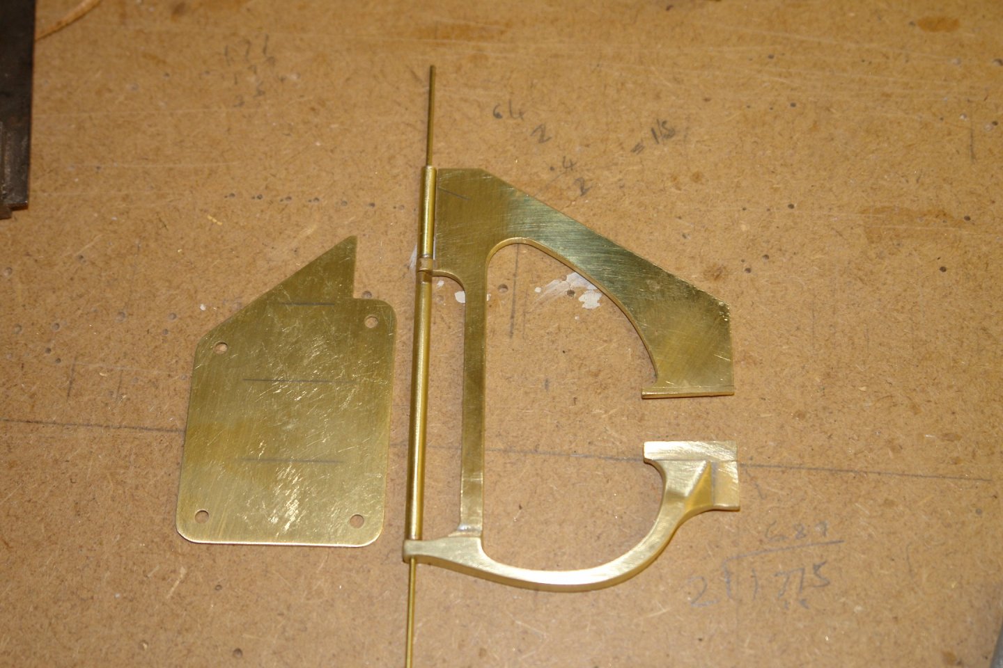
I will form the outer shape of the rudder by attaching mahogany to each side and then sanding to shape. Below the mahogany "cladding" has been cut and glued prior to attaching to the rudder shaft.
That's all for now.
- FlyingFish, gjdale, FriedClams and 12 others
-
14
-
 1
1
-
13 hours ago, wefalck said:
I would have tried to silver-solder the boss on, but the large brass-piece might have drawn too much heat.
Eberhard - that was my worry and I also thought the method I chose was potentially the easiest to guarantee alignment between the upper and lower bearing holes.
11 hours ago, TBlack said:I need one of those.
Tom - relatively cheap from Amazon or Ebay. And yes they are excellent for waterlines.
Thank you Eberhard, Tom, Druxey, Rick, John and Nils.
And thank you to the usual crew of followers for the likes.
- druxey, Keith Black, Mirabell61 and 2 others
-
5
-
On 4/5/2024 at 10:30 PM, FlyingFish said:
reasons all caught in the same dozy moment.
I find that the older I feel the Dozier I get, and I can't even blame it on late nights. Remember every failure is an opportunity for improvement.😀
- FriedClams, mtaylor, Keith Black and 1 other
-
4
-
On 4/7/2024 at 5:14 AM, gak1965 said:
It is the hardest piece of bass I have ever seen.
That's the problem with natural products - they tend to be quite variable. It seemed to workout quite well.
- FriedClams, Keith Black and mtaylor
-
3
-
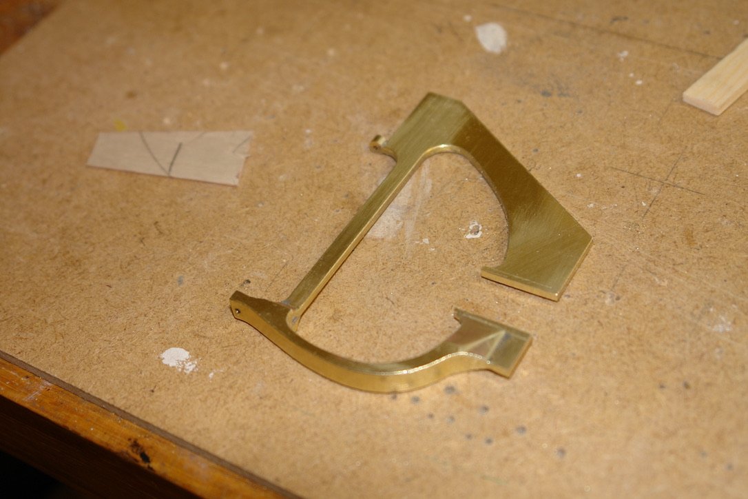
A little more progress on the rudder frame.
Thank you Rick / Richard -
On 4/1/2024 at 10:02 PM, Retired guy said:I am sure you will use the mill first, then file to shape
Exactly so Richard.
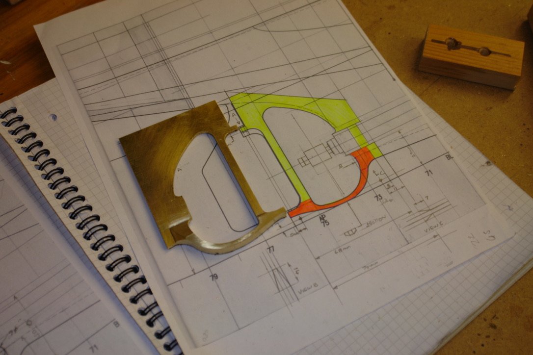
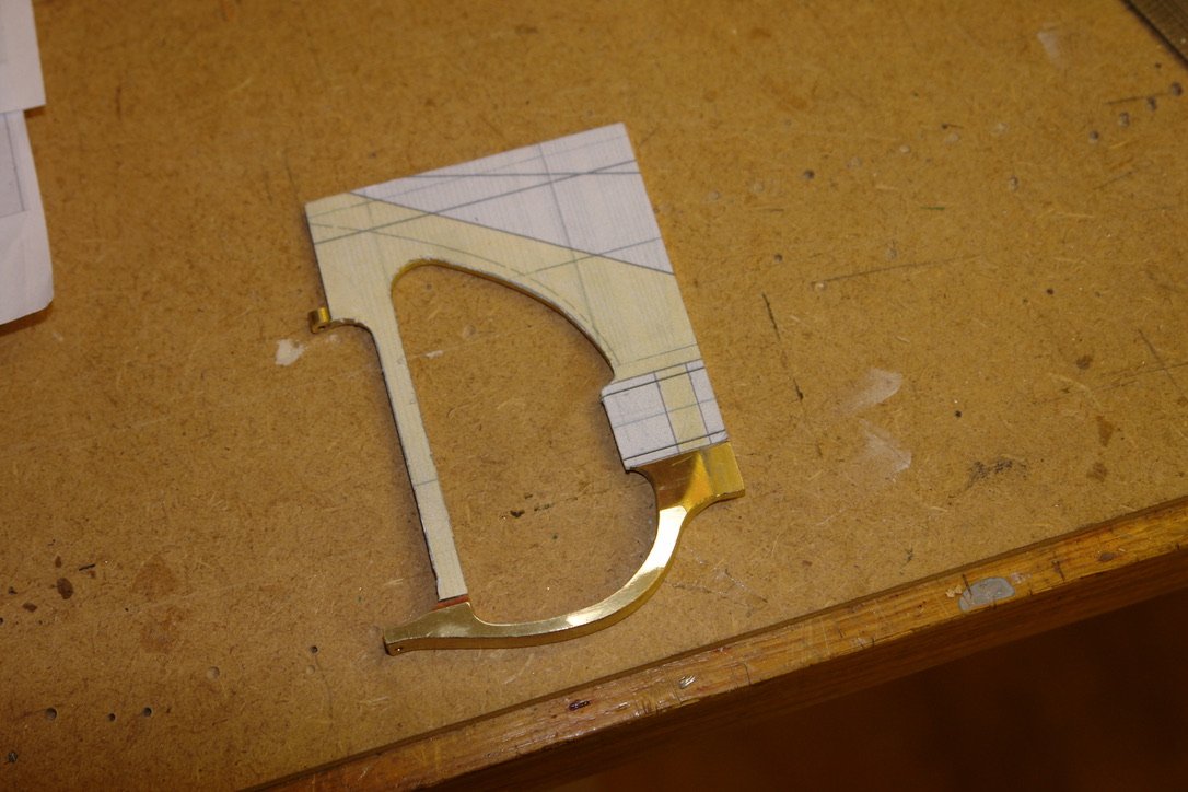
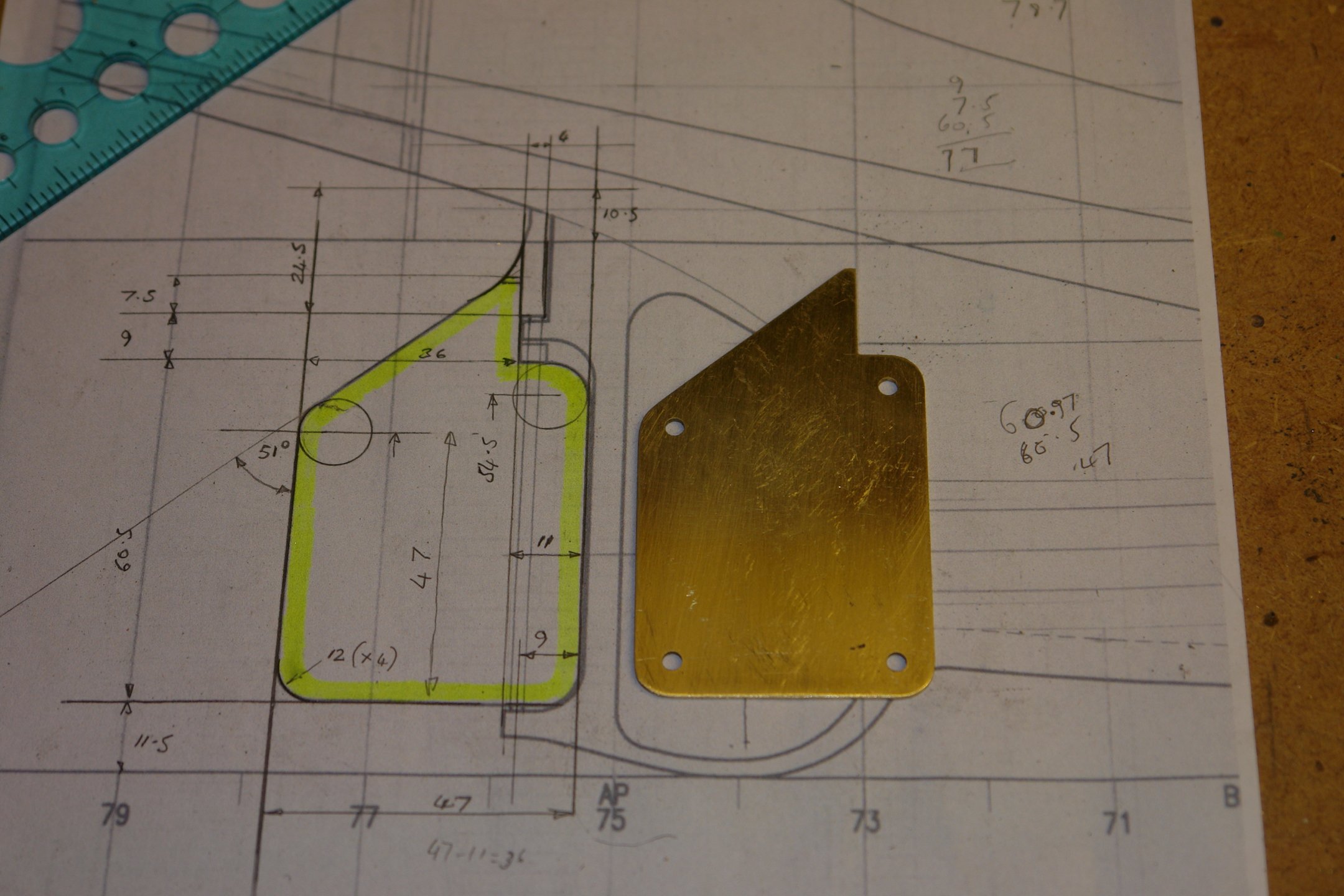
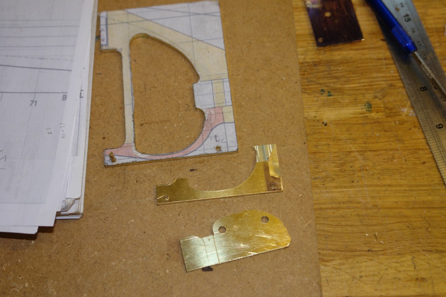
I am still using paper templates to get the shapes right.
The wedge angles produce a little distortion in the templates but nothing worth worrying about.
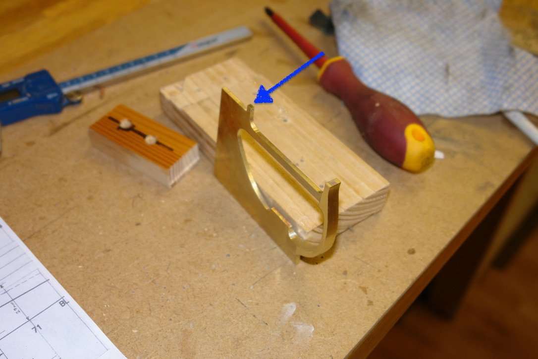
I cut the bulk of the excess metal away with straight cuts using my hacksaw. I then clamped the frame to a piece of wood for a bit of milling.
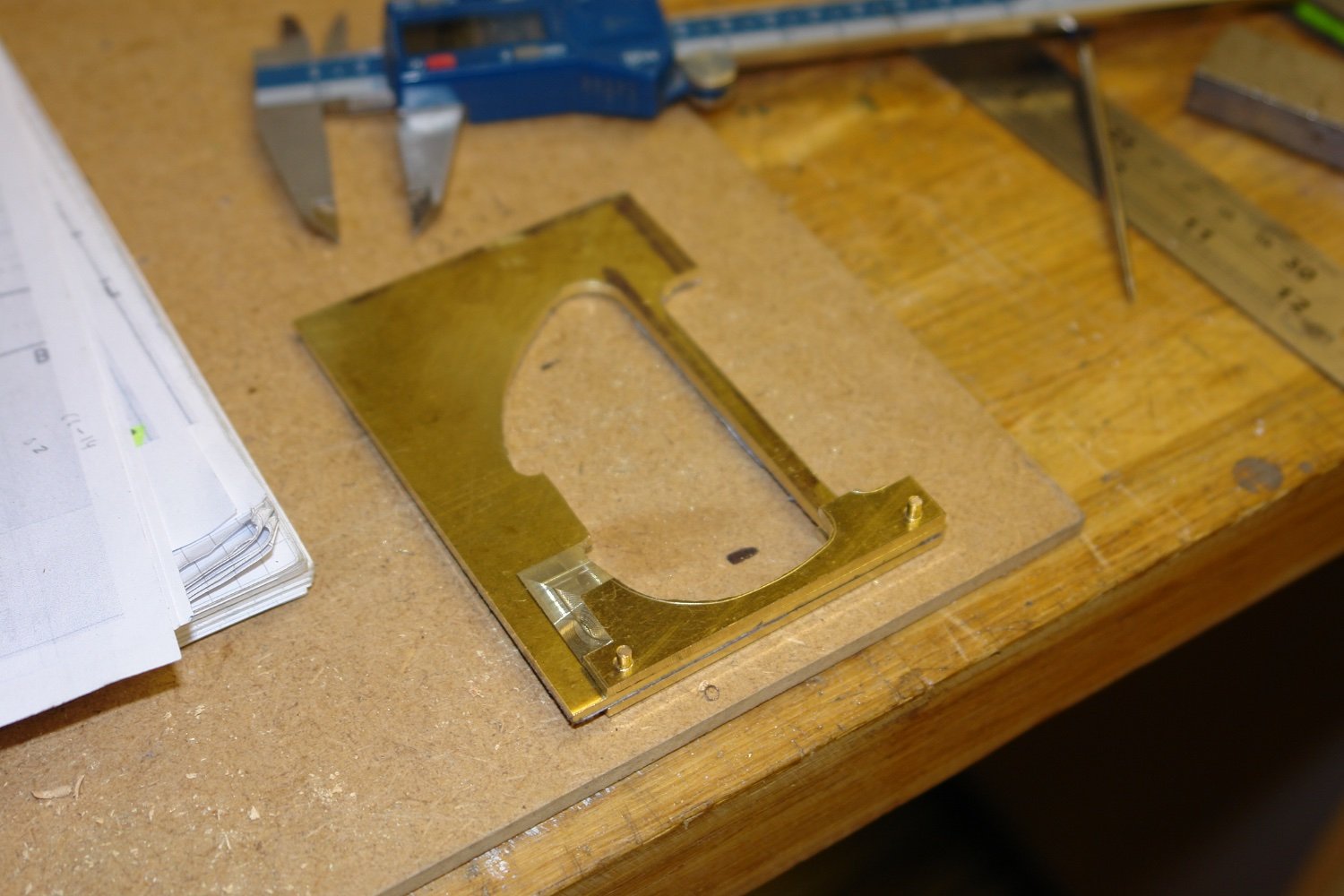
I nibbled my way towards the desired profile using an end mill cutting vertically.
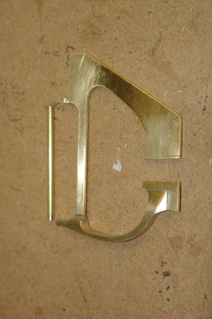
I then blended the frame to shape with various files. I also drilled holes (upper and lower) to take the rudder shaft.
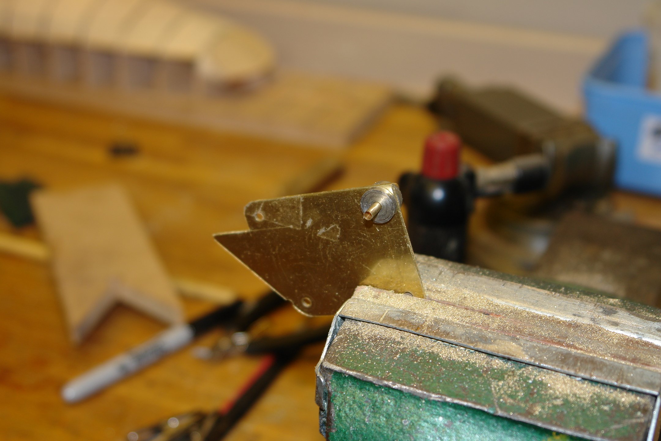
The frame around the upper rudder bearing is round and not square as currently formed.
 So I needed to form the 4mm diameter round boss. I did this by first slotting out the end of a piece of 4mm diameter rod.
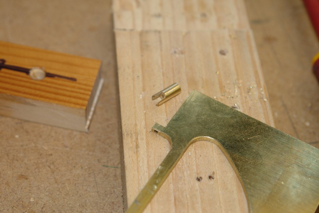
This was then placed over square section nib and soldered in place.
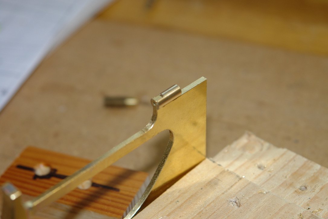
The excess was then cut away and the boss was cleaned up with a file.
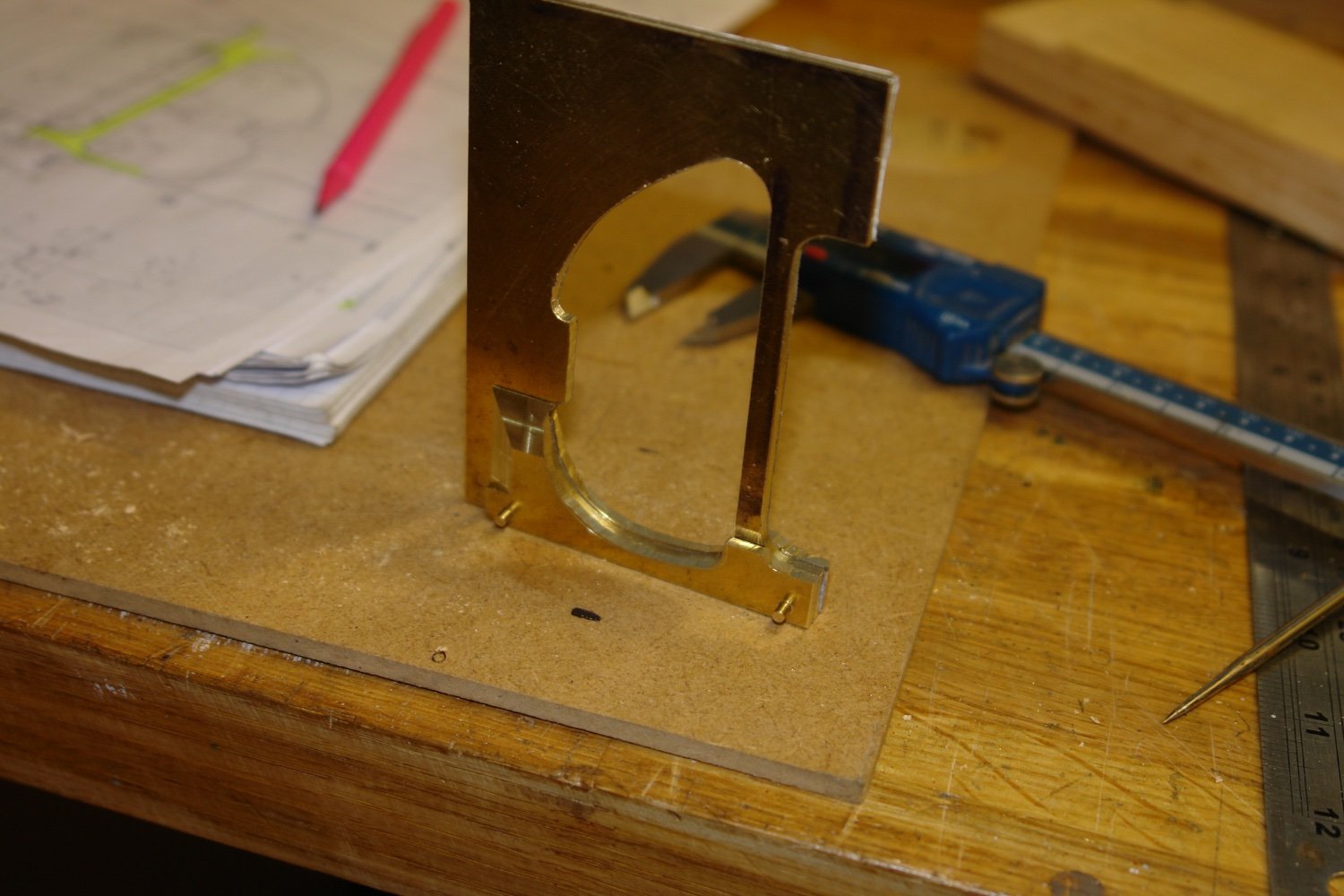
Finally a paper template was used again prior to cutting away the waste.
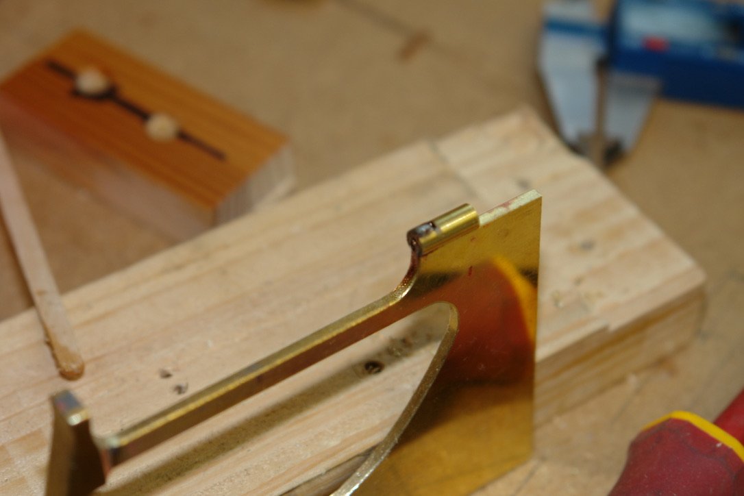
The frame was then test fitted into the pre made slot in the hull.
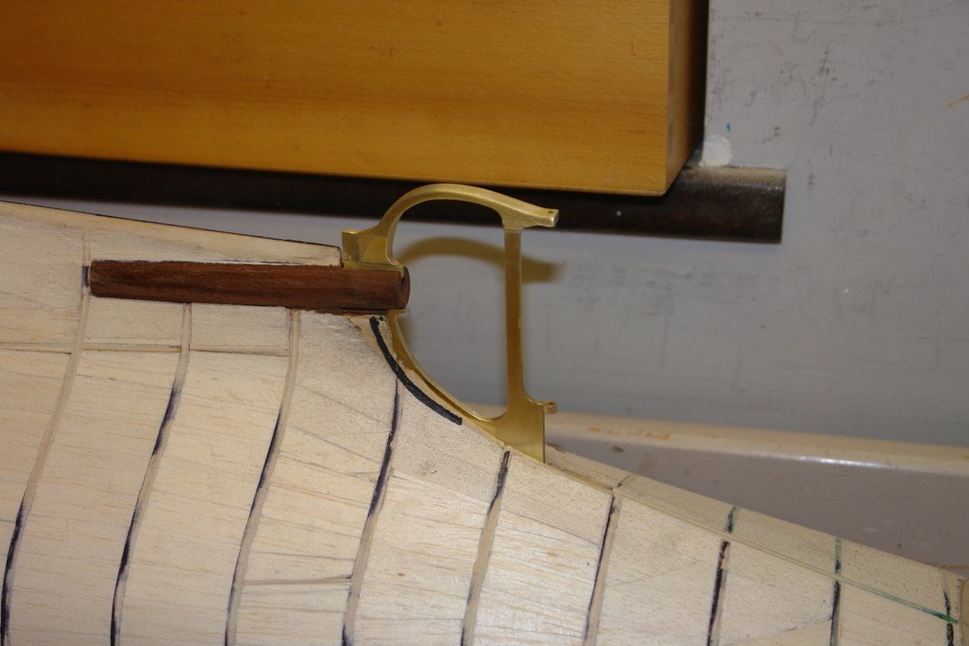
Although not fixed in position I checked the alignment with a laser level.
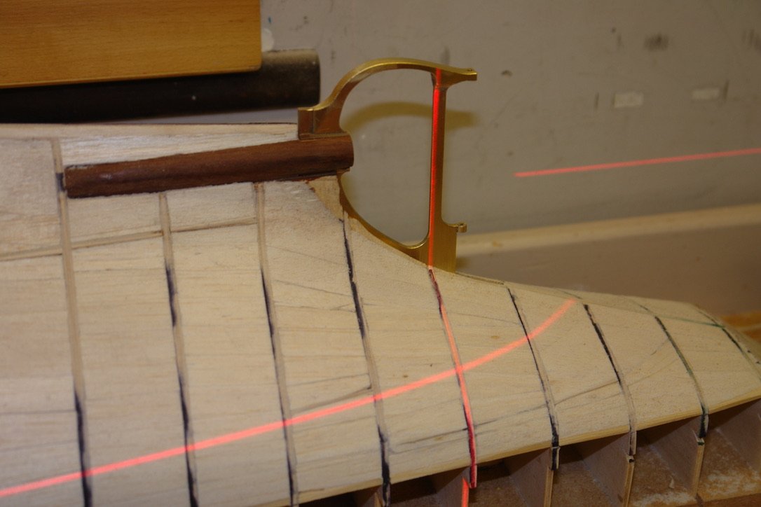
The frame isn't finished as it needs a fair bit of polishing with wet and dry paper before finishing on the polishing wheel.
Next the rudder.
- Mark Pearse, mtaylor, GrandpaPhil and 17 others
-
16
-
4
-
Not withstanding your trials and tribulations the hull painting turned out remarkably well. The red waterline is particularly crisp.
-
-
On 4/2/2024 at 4:10 PM, vaddoc said:
I rushed to buy some of the Humbrol enamels before they are pulled out of the market - apparently one of the ingredients is now banned in Europe.
Thank you for the tip. I'd better stock up before they ruin them. like Colron wood dye and Nitromors paint stripper.
- mtaylor and FriedClams
-
2
-
Great progress Nils. I am feeling a bit dumb because it was only in your last few posts that I realised she has a means of propulsion. The Trinity House light ships I am more familiar don't have propulsion and are towed on and off station.
- FriedClams, mtaylor, FlyingFish and 3 others
-
5
-
 1
1
-
-
Mike - i hadn't considered using a scroll saw. I don't have any metal cutting scroll saw blades other than the very fine jewellers saw blades. I really need to order some. I think I can manage the cut with a combination of hacksaw and mill.
Thank you John and also thank you to anyone else who has left a like.
- Retired guy, mtaylor, Keith Black and 1 other
-
4
-
My daughter has gone off on what she calls a sabbatical. So far as I can tell this involves an extended holiday from work drifting around Europe chasing the snow. She parked her car here before she went which is how I discovered that it was more of a garbage truck than a family vehicle. Anyway, today I spent 6 hours getting it back to being tolerably habitable. The good news is that I found enough half eaten snacks to replenish our pantry for the foreseeable future. Unfortunately I didn't find any money. Today wasn't very productive in the shed but fortunately I did get some time yesterday.
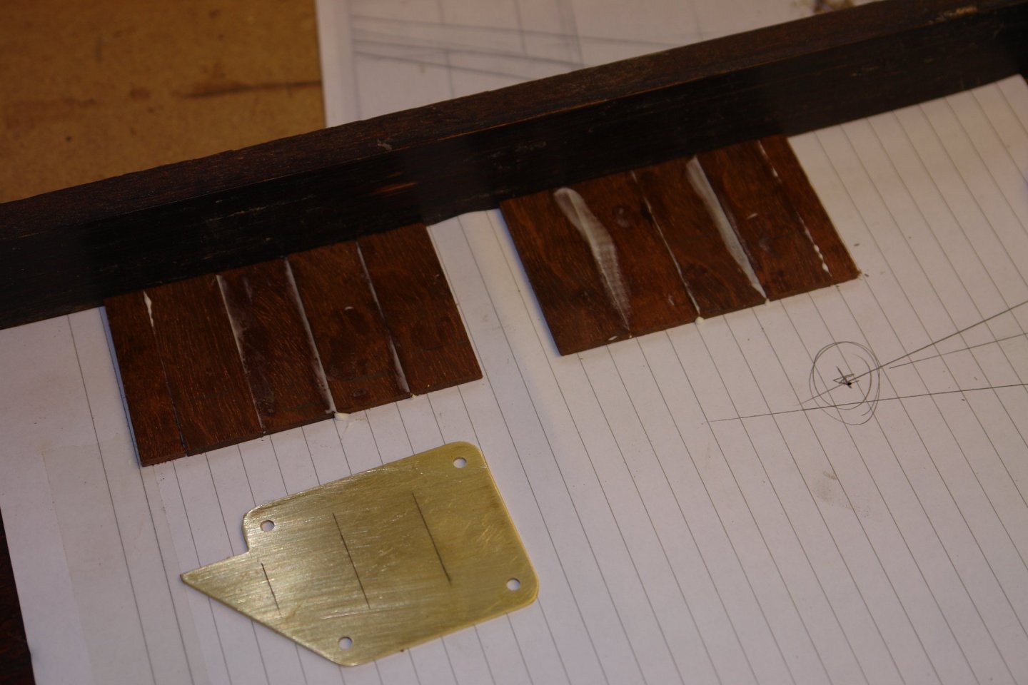
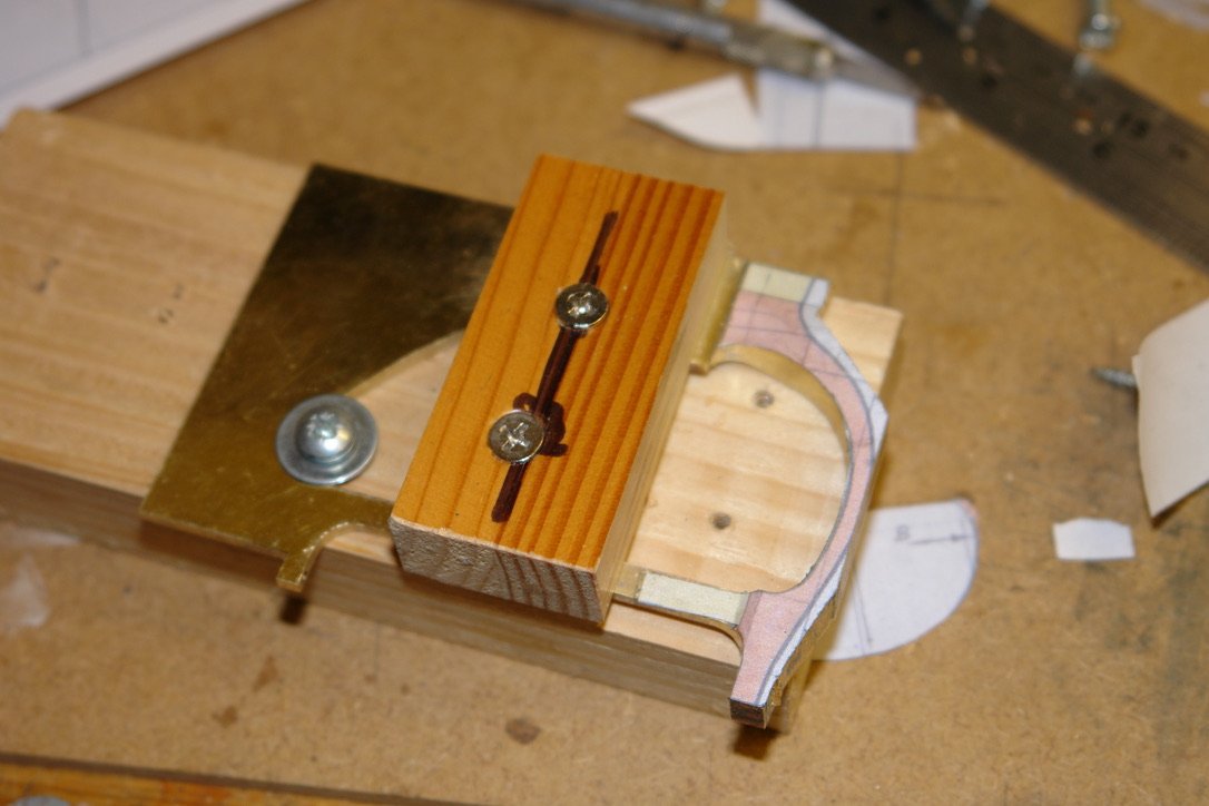
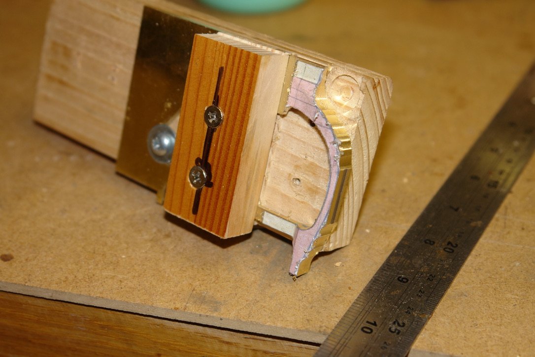
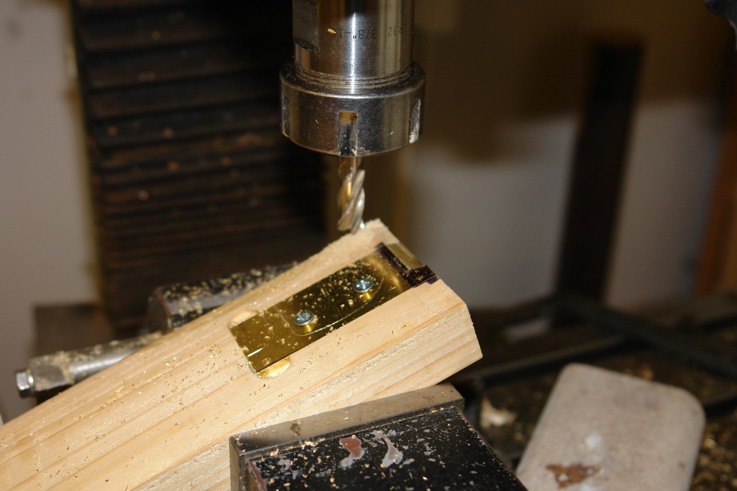
I started by machining the wedge angles on the edges of the rudder frame outer thickening pieces. I used a block of wood to hold the pieces on the mill at the correct angle, the angle being set using a bit of trigonometry. I don't have one of those clever little digital angle gauges but sometimes the old methods work perfectly well. You can see in the picture that the thickening pieces are screwed to the wood, but what is less apparent is that they are set in a cut out which supports them on 3 sides. I decided that relying on the screws alone probably wouldn't have worked.

I machined both thickening pieces without removing the wooden block from the vice - thus ensuring that the wedge angles on the 2 thickening pieces were identical.

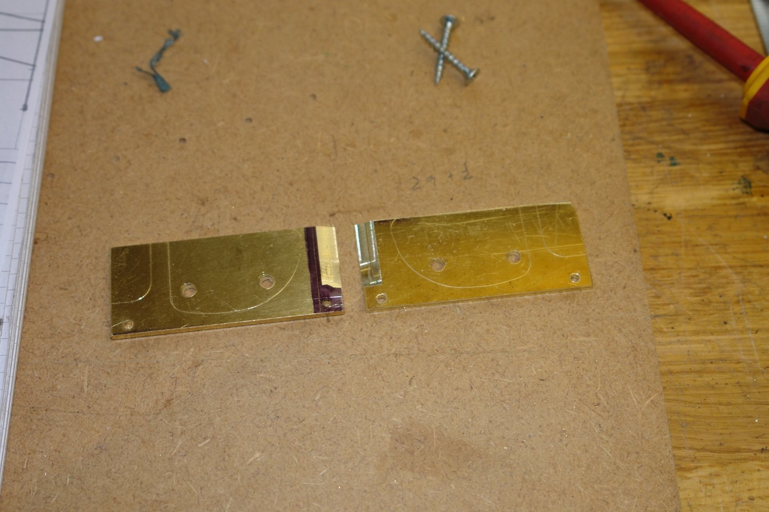
Using a similar technique I machined the other two wedge angles with a different block set at a different angle. You can also see that I used the central piece as a template for scribing on the final internal shape of the thickening pieces.

Then it was back to the jewellers saw to cut out the internal shape. I still hadn't ordered the coarse saw blades so inevitably it took longer than it should have with more breakages. Old fools never learn!

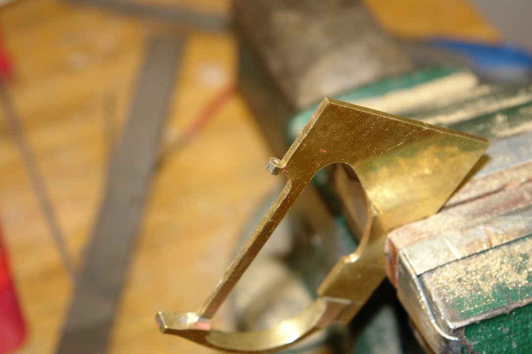
I then machined on the final chamfers on the little nib on the left hand side in the above shot. The three pieces were then assembled together using the small brass locating pins.


The assembly was held together with stainless steel clothes pegs and flux, solder and heat were applied to turn the three pieces into one. Apologies for the messy soldering, I was rushing a bit.
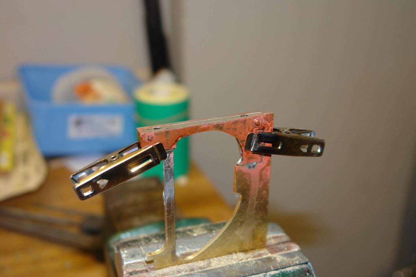
The good news is that it cleaned up quite well.
Now I have to cut the bottom profile which of course is now 0.3" thick and well beyond the wildest aspirations of my little jewellers saw. I need a different plan.
- GrandpaPhil, Ian_Grant, FlyingFish and 12 others
-
13
-
2
-
On 3/29/2024 at 3:58 PM, wefalck said:
It took several tries to produce these tiny pieces. In the end their dimensions are slightly over-scale due to the limitations of machining brass. Starting from 0.8 mm brass-nails,
Wonderful work Eberhard.
When I have needed small diameter hardened brass in the past I have taken a length of brass wire and put one end in a drill chuck while clamping the other end in a vice. While keeping the wire taught I have turned on the drill for a few seconds to twist the wire, thus work hardening and straightening it at the same time. I got the idea from looking closely at some 0.6 mm brass rod supplied by Cornwall model boats. under the magnifying glass you could see a definite helix along its entire length. Unfortunately I don't have a ready supply of brass nails.
- mtaylor, Keith Black, Ras Ambrioso and 3 others
-
6
-
Keith . My wife, daughter and daughter-in-law swear by these books. They all have dishes where you load all the food on one tray and bung it in the oven and about 45 minutes later you have a very tasty meal. I can confirm the food is very good and the washing up is minimal. I don't know if you can get them in the USA but it is worth looking.

Here is a review - https://vaithehy.co.uk/2020/07/book-review-the-quick-roasting-tin.html
- BANYAN, FriedClams, Keith Black and 3 others
-
5
-
1
-
On 3/12/2024 at 1:57 PM, Keith Black said:
I wish I was younger, I wish I was a better cook, I wish a lot of things but it is what it is and one gets through this one hour at a time, one day at a time.
Hats off to you Keith, it seems to me that you are doing a marvellous job. You will know you are on the home straight when Maggie starts complaining about the cooking and offers to take over.
- Keith Black, FriedClams, TBlack and 4 others
-
6
-
1
-
-
Looking very smart Valeriy.
- Valeriy V, mtaylor, Keith Black and 2 others
-
5


Caroline N by mbp521 - Scale 1:64 - Mississippi River Towboat
in - Build logs for subjects built 1901 - Present Day
Posted
Ah! - that makes perfect sense.