KeithAug
-
Posts
3,246 -
Joined
-
Last visited
9 Followers


Recent Profile Visitors
6,027 profile views


-
 mbp521 reacted to a post in a topic:
Peerless by Cathead - 1:87 - 1893 sternwheel Missouri River steamboat
mbp521 reacted to a post in a topic:
Peerless by Cathead - 1:87 - 1893 sternwheel Missouri River steamboat
-
Cathead reacted to a post in a topic:
Peerless by Cathead - 1:87 - 1893 sternwheel Missouri River steamboat
-
Keith Black reacted to a post in a topic:
Peerless by Cathead - 1:87 - 1893 sternwheel Missouri River steamboat
-
BANYAN reacted to a post in a topic:
Steam Yacht Cangarda 1901 by KeithAug - Scale 1:24 - 1901/2008
-
BobG reacted to a post in a topic:
Steam Yacht Cangarda 1901 by KeithAug - Scale 1:24 - 1901/2008
-
 mbp521 reacted to a post in a topic:
Caroline N by mbp521 - Scale 1:64 - Mississippi River Towboat
mbp521 reacted to a post in a topic:
Caroline N by mbp521 - Scale 1:64 - Mississippi River Towboat
-
Jack12477 reacted to a post in a topic:
Peerless by Cathead - 1:87 - 1893 sternwheel Missouri River steamboat
-
Retired guy reacted to a post in a topic:
Lightship ELBE 1 by Mirabell61 - scale 1:87 - launched 1948
-
KeithAug reacted to a post in a topic:
Flying Fish by MikeR - 1:64 (3/16" to 1 Foot) - from Model Shipways plans
-
Keith Black reacted to a post in a topic:
Caroline N by mbp521 - Scale 1:64 - Mississippi River Towboat
-
Keith Black reacted to a post in a topic:
Steam Yacht Cangarda 1901 by KeithAug - Scale 1:24 - 1901/2008
-
KeithAug reacted to a post in a topic:
Steam Yacht Cangarda 1901 by KeithAug - Scale 1:24 - 1901/2008
-
KeithAug reacted to a post in a topic:
Paddlewheeler Golden City by Louie da fly - Scale 1:50 and 1:25 - solid hull
-
KeithAug reacted to a post in a topic:
Lightship ELBE 1 by Mirabell61 - scale 1:87 - launched 1948
-
KeithAug reacted to a post in a topic:
SS Blagoev (ex Songa )1921 by Valery V - scale 1:100 - Soviet Union
-
KeithAug reacted to a post in a topic:
SS Blagoev (ex Songa )1921 by Valery V - scale 1:100 - Soviet Union
-
 Beautiful planking job Mark.
 -
KeithAug reacted to a post in a topic:
Ranger type yacht by Mark Pearse - 1:12 - SMALL
-
KeithAug reacted to a post in a topic:
Ranger type yacht by Mark Pearse - 1:12 - SMALL
-
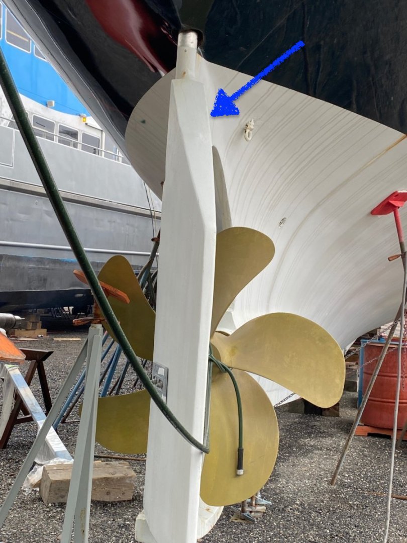
Quite an update Brian. Everything is looking really smart, your rails turned out really well. Fascinating rudder arrangement, although I am not quite sure why the designers took that approach.
-
Hi Rick - yes let us hope she goes to a good home. I fear that she isn't suitable for the usual super yacht brigade. Welcome Bob I hope you enjoy the remainder of the build, you may need to patient I am not fast.
-
KeithAug reacted to a post in a topic:
Steam Yacht Cangarda 1901 by KeithAug - Scale 1:24 - 1901/2008
-
KeithAug reacted to a post in a topic:
Steam Yacht Cangarda 1901 by KeithAug - Scale 1:24 - 1901/2008
-
Eberhard - thank you - my current thought is to paint the hull above the waterline to match the original but to varnish below the waterline to show off the mahogany and brass. it is still early days and plans might change depending on how neat the planking is. Druxey - Thank you ----- and the angle can be changed by moving it in or out from the edge. And thank you to the Black twins for their unrelenting support.🙂
-
Excellent progress Nils. I look forward to the next instalment.
- 119 replies
-
- 3
-
-
- lightship
- Feuerschiff Elbe 1
- (and 1 more)
-
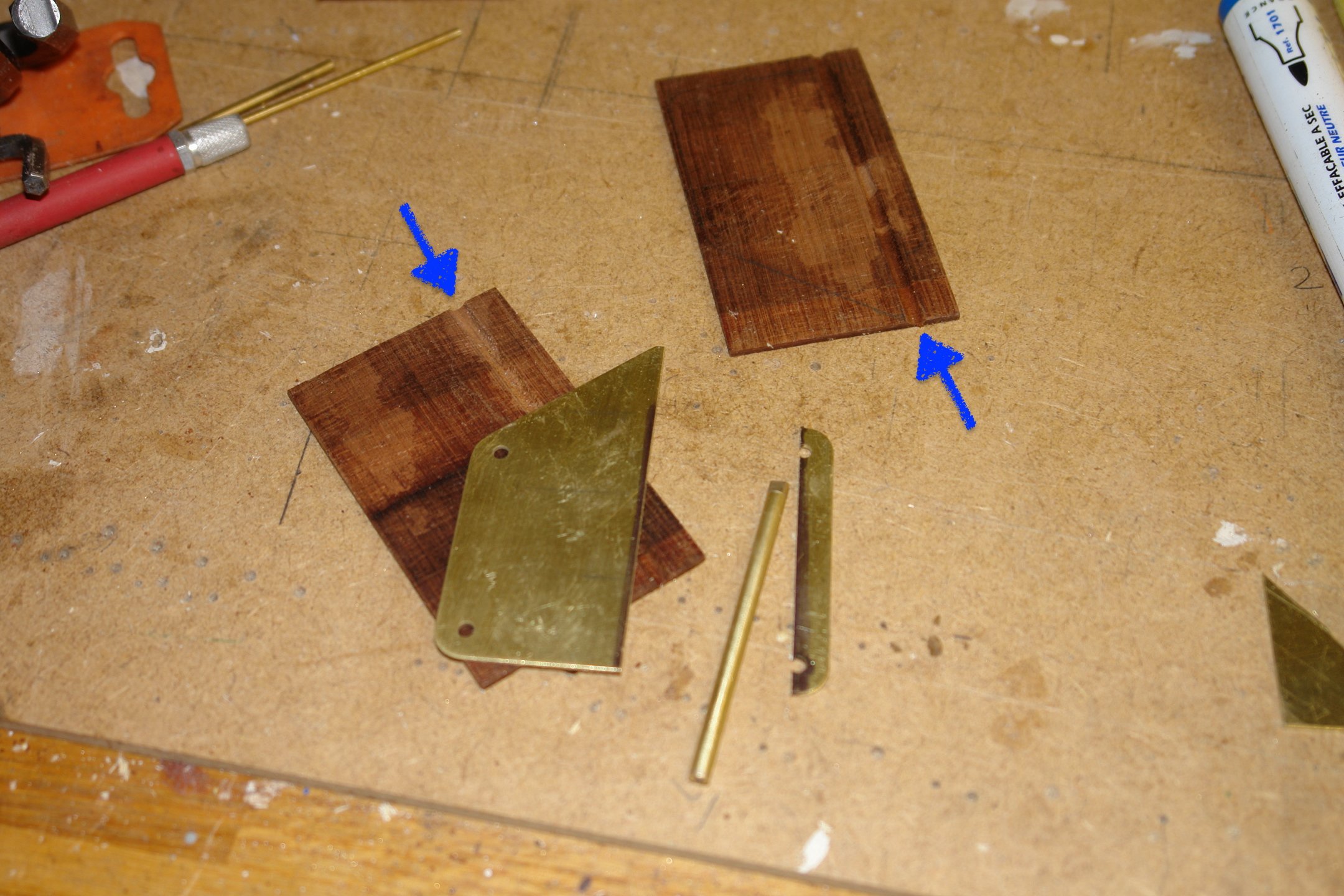
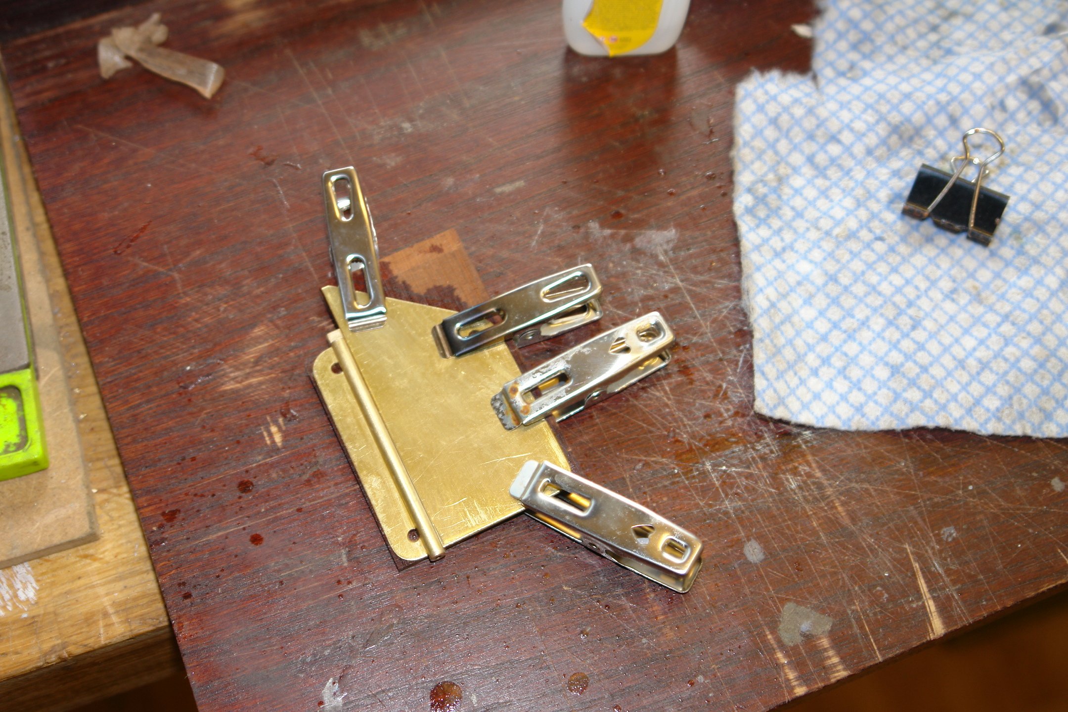
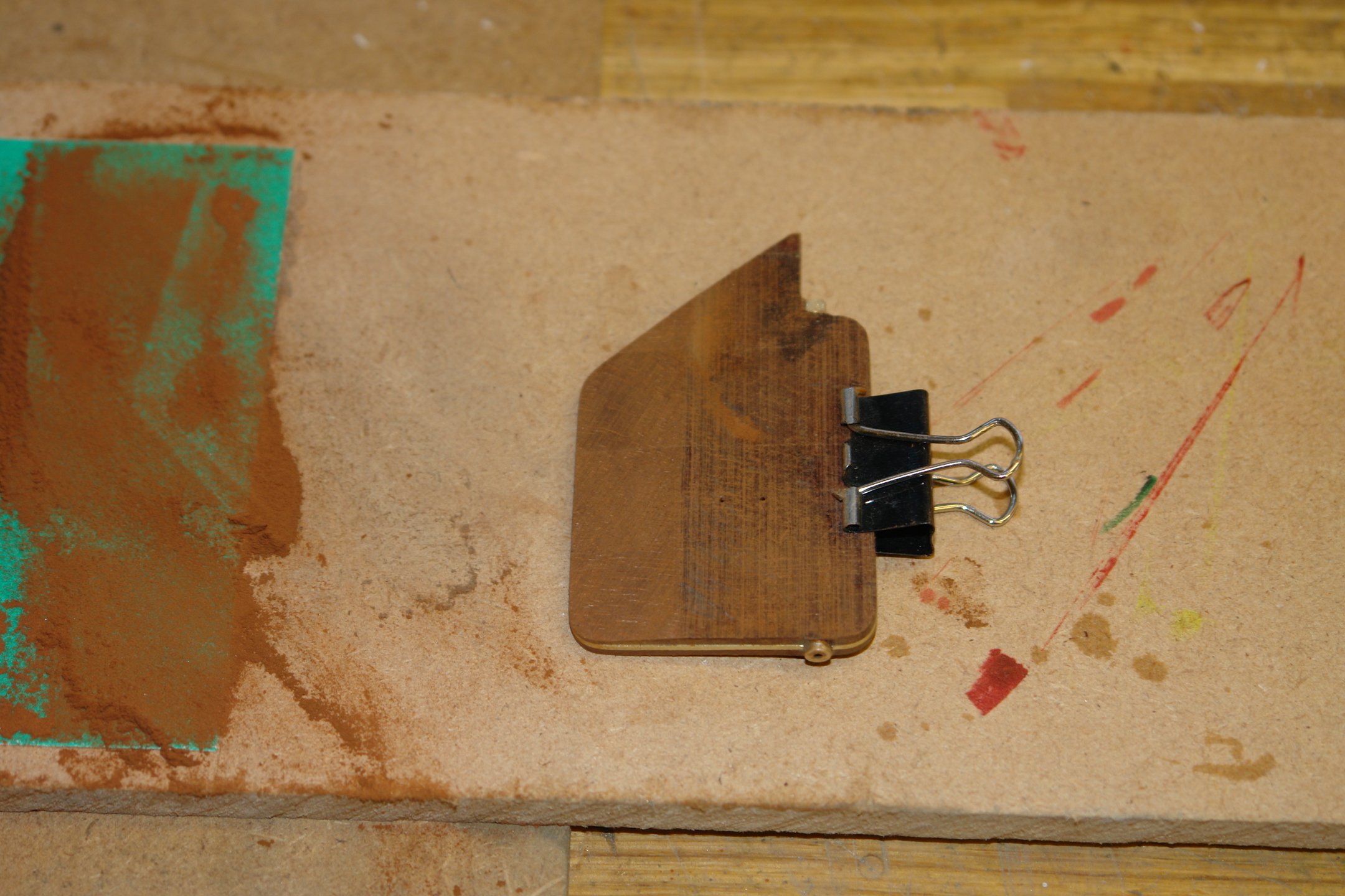
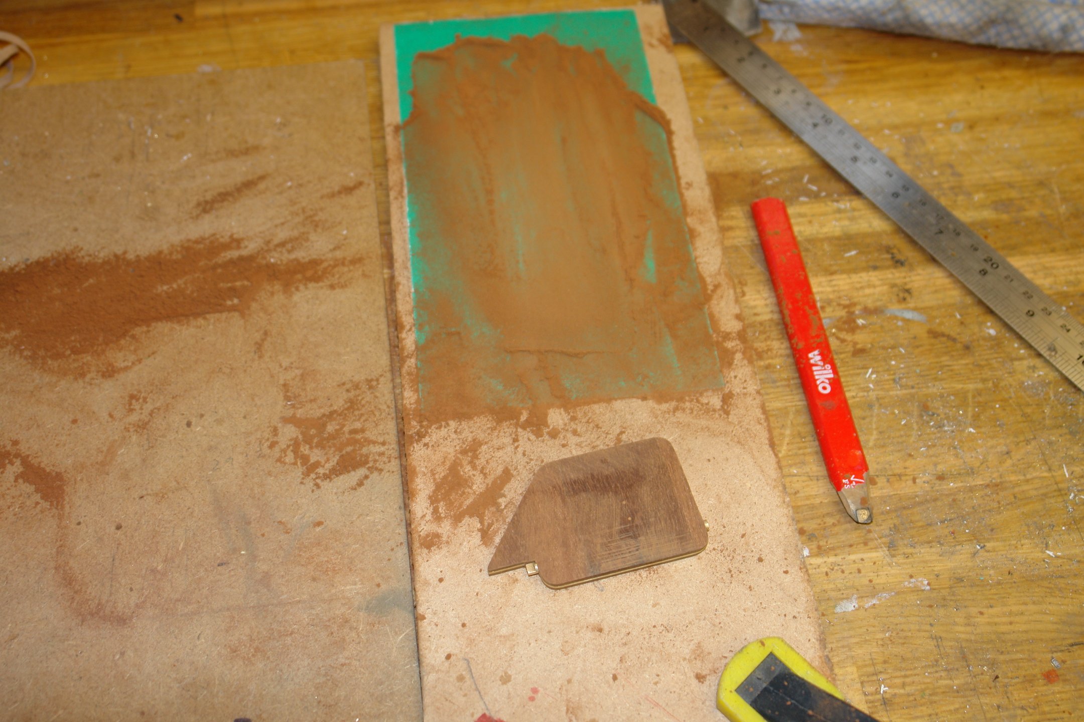
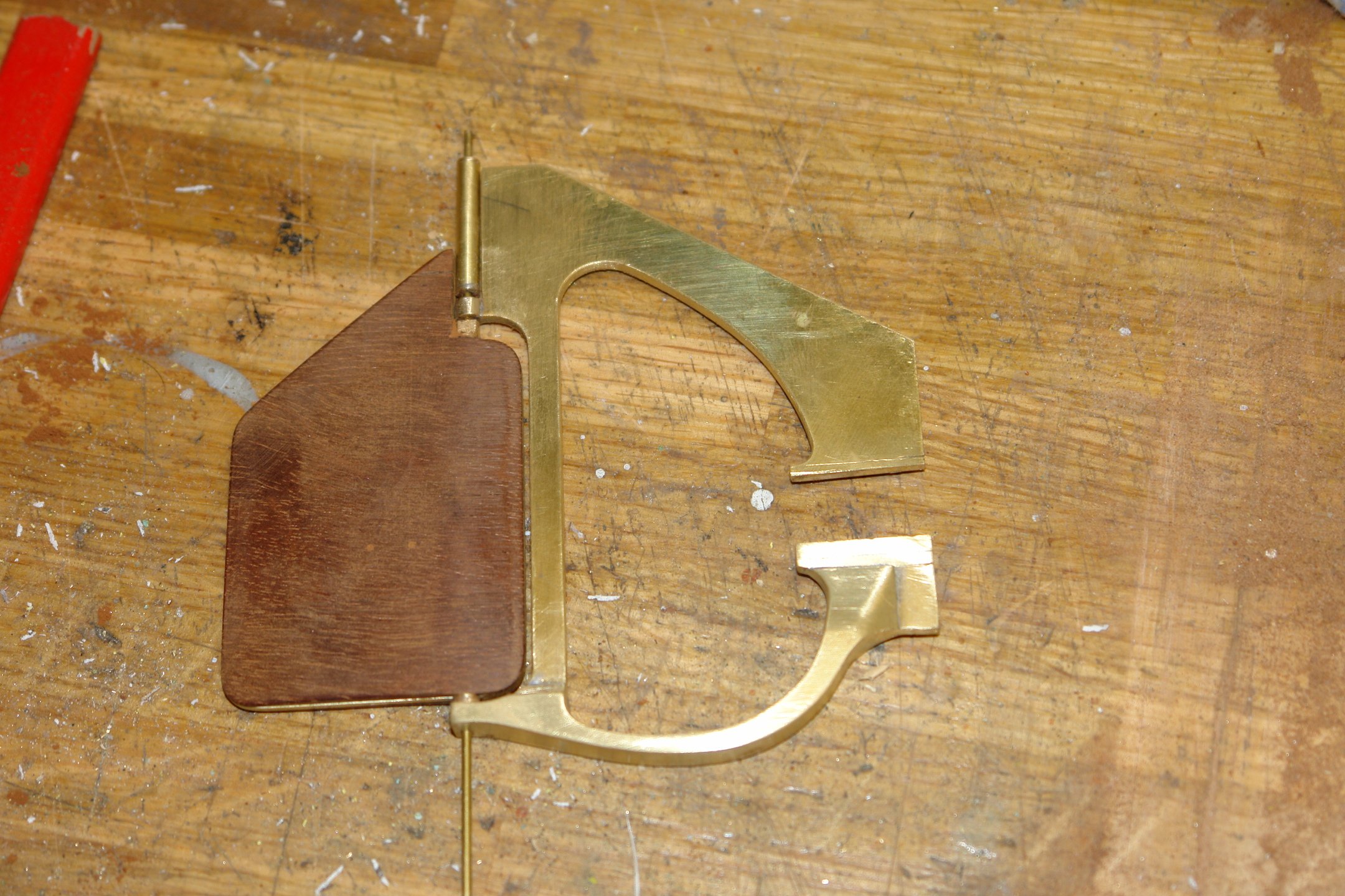
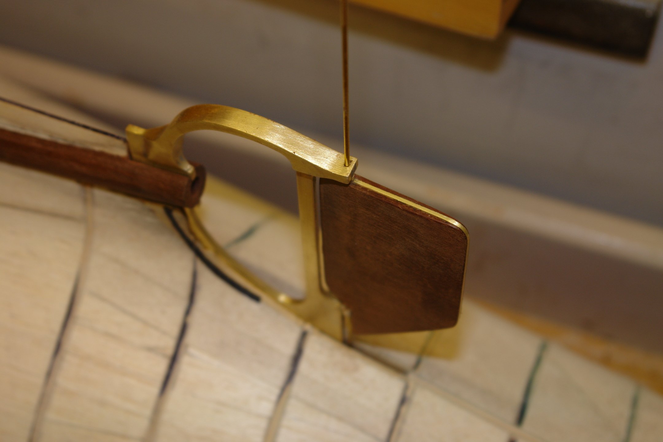
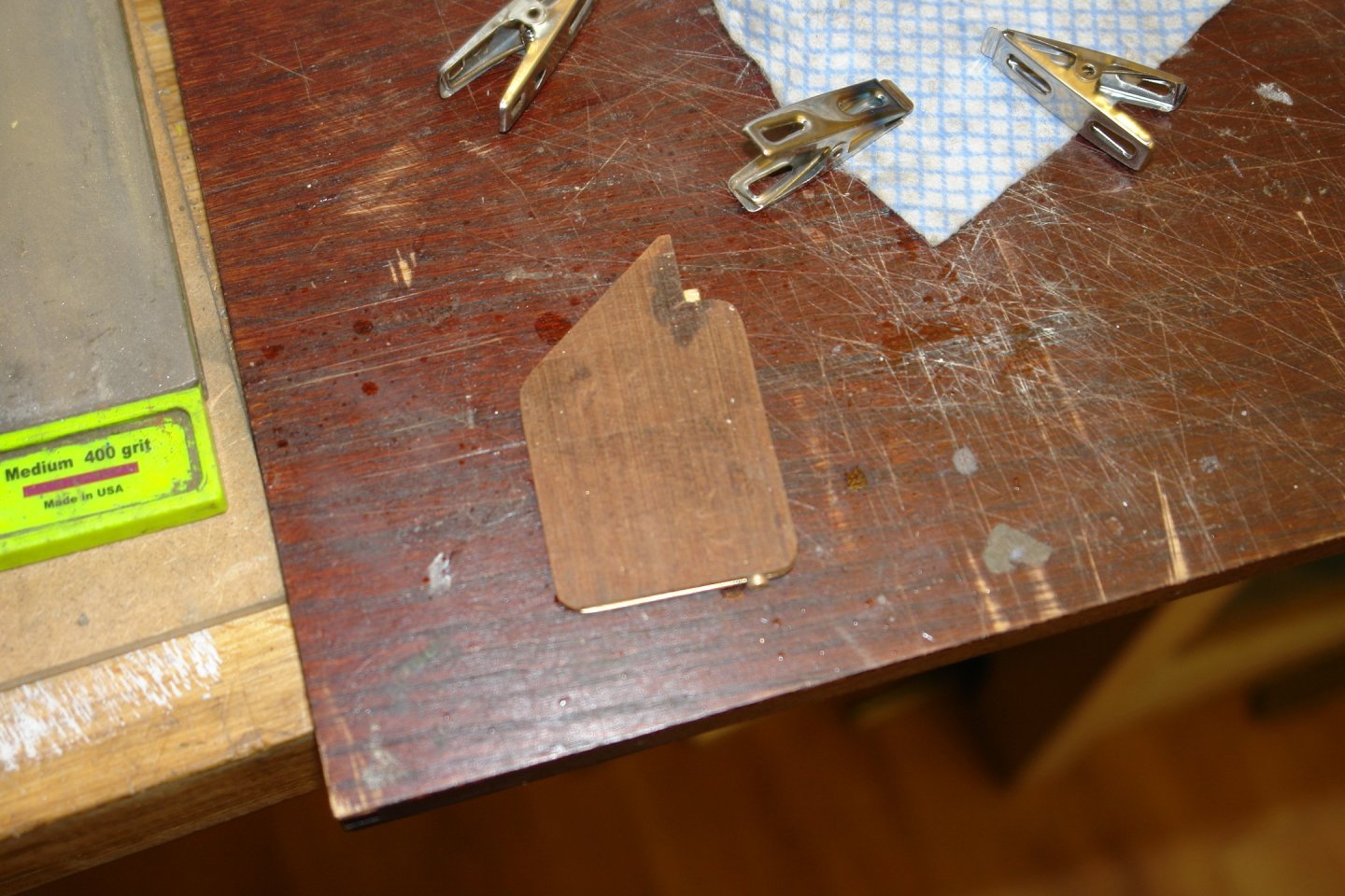
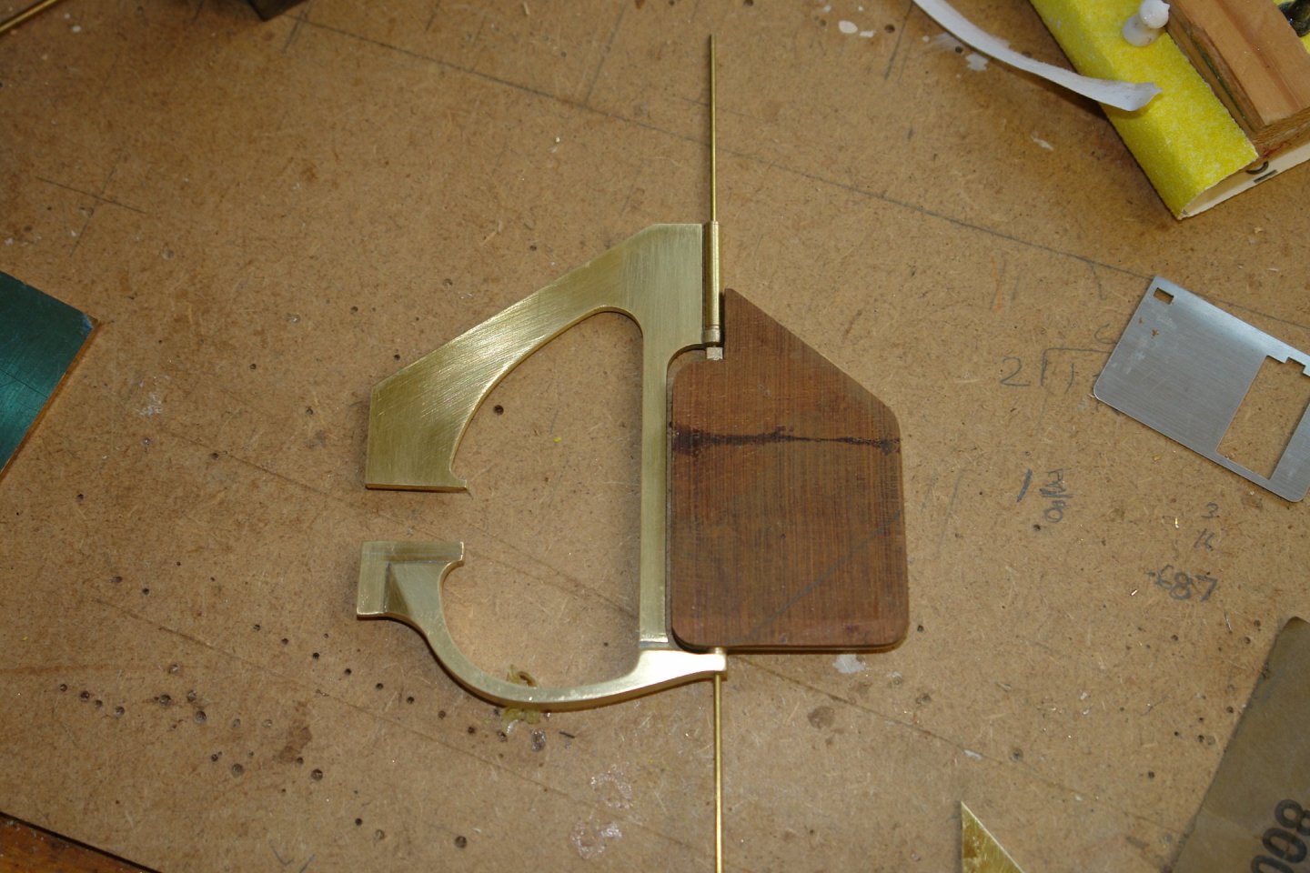
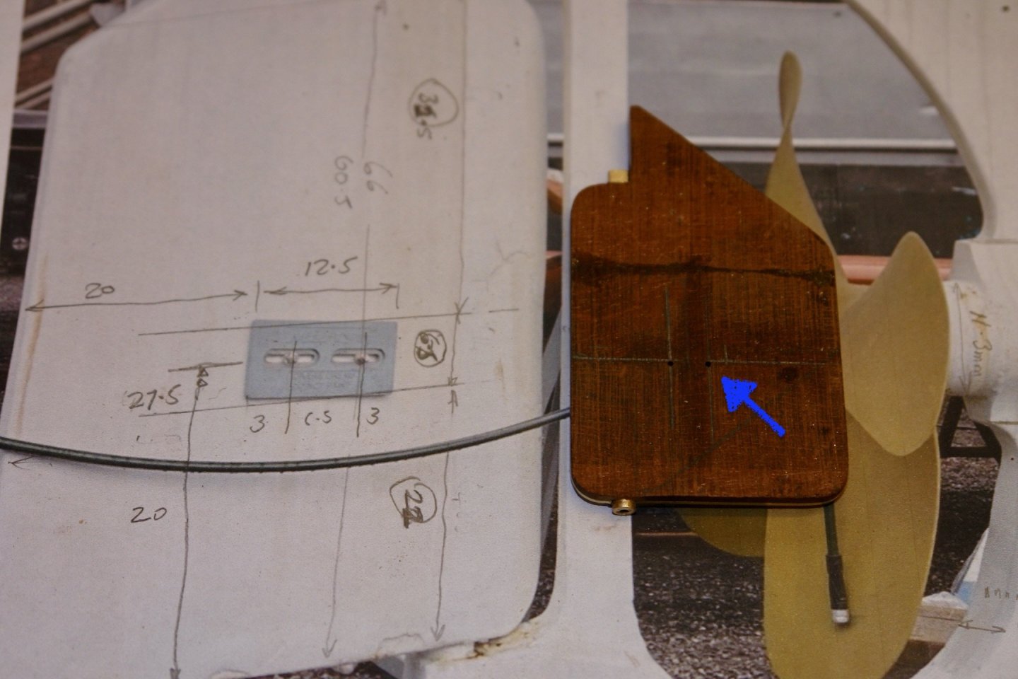
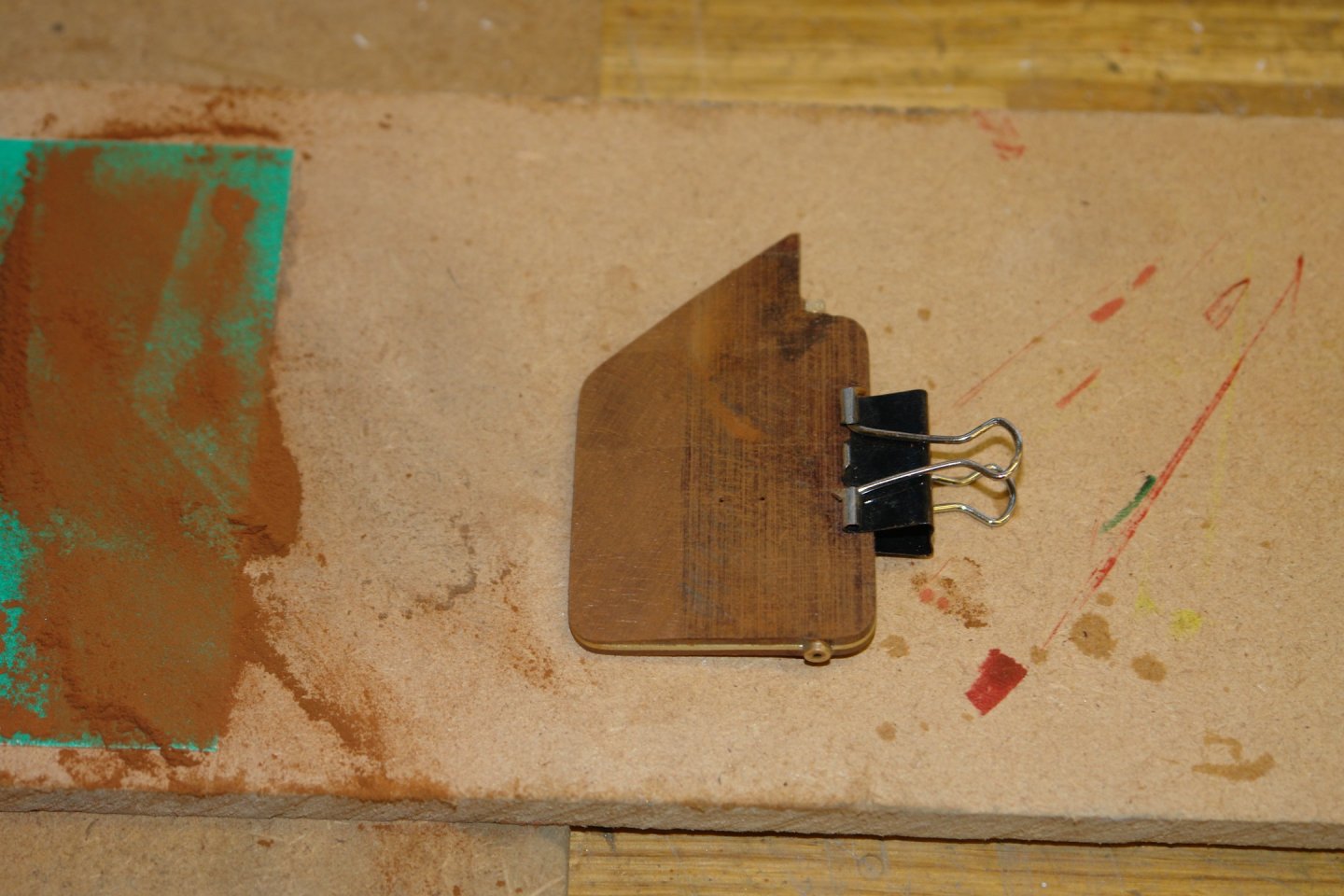
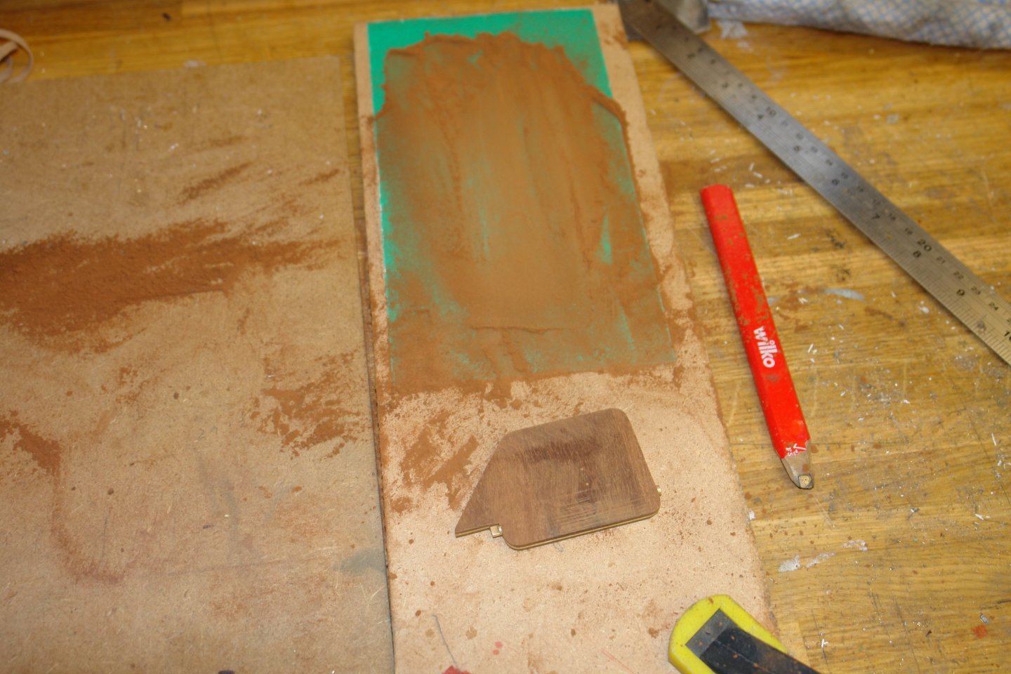
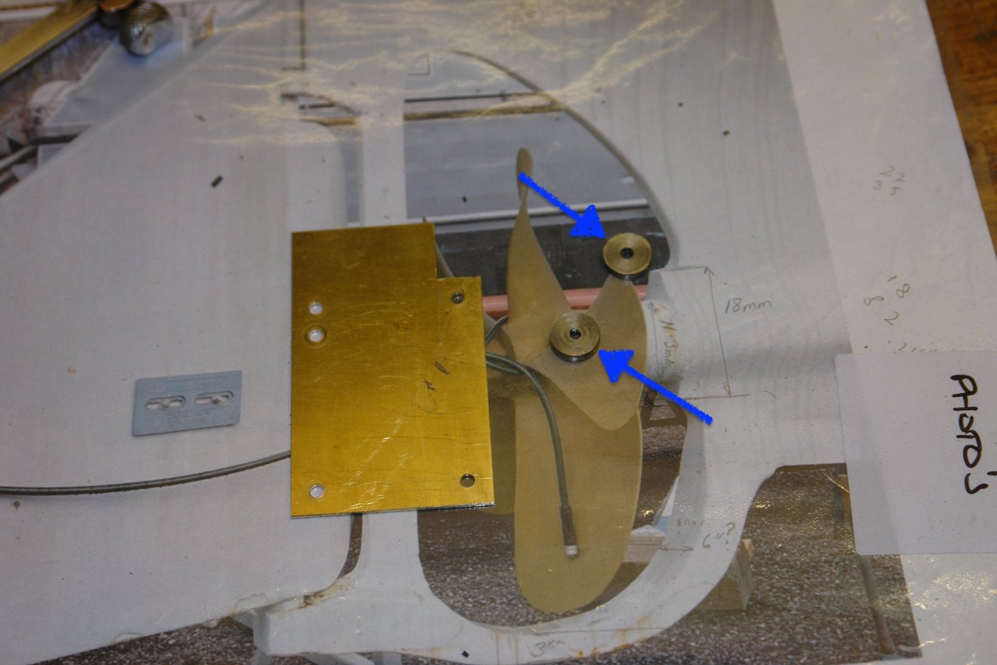
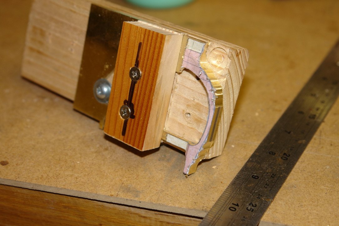
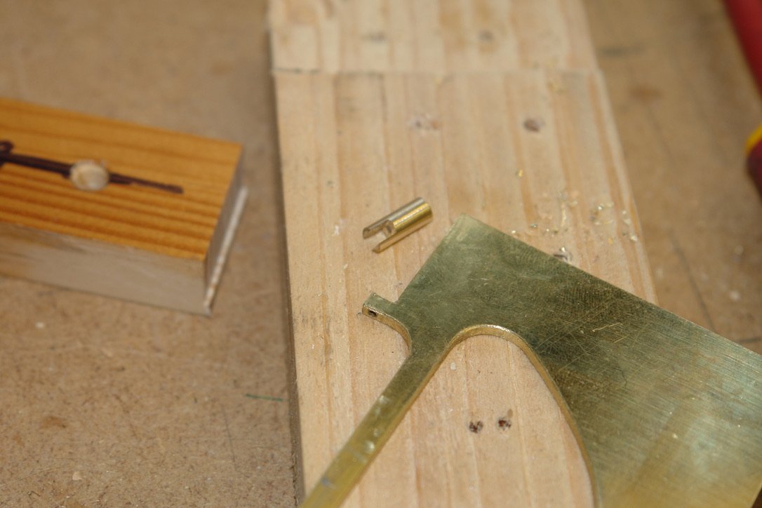
Thank you Andy and John. I spent a few hours today completing the rudder (excluding finishes). The shaft is 0.16" diameter while the plate is .04" thick. I therefore needed to machine slots in the the cladding 0.08" radius by 0.06" deep. See blue arrows on next photo. I also cut the plate along the line of the shaft removing a .016" wide strip. The brass pieces were then assembled on the cladding and glued in place using CA glue. The other side of the gladding was then glued in place forming a brass sandwich. The rudder is fitted with anodes. All the anodes on Cangarda are of the same flat plate type. I drilled the holes for later anode attachment. To get the taper sanding of the cladding symmetrical I employed a flat sheet of aluminium oxide paper and a bulldog clip. The bulldog clip is holding the front of the rudder clear of the sandpaper and at a constant angle while the taper is sanded. The bulldog clip spring is hard enough to resist the abrasion of the oxide paper. The taper on the front edge of the rudder was formed in a similar manner. My plan is to get on to the planking next. I expect it to be a long job so if you want to skip it I suggest you rejoin in about 2 months.


-
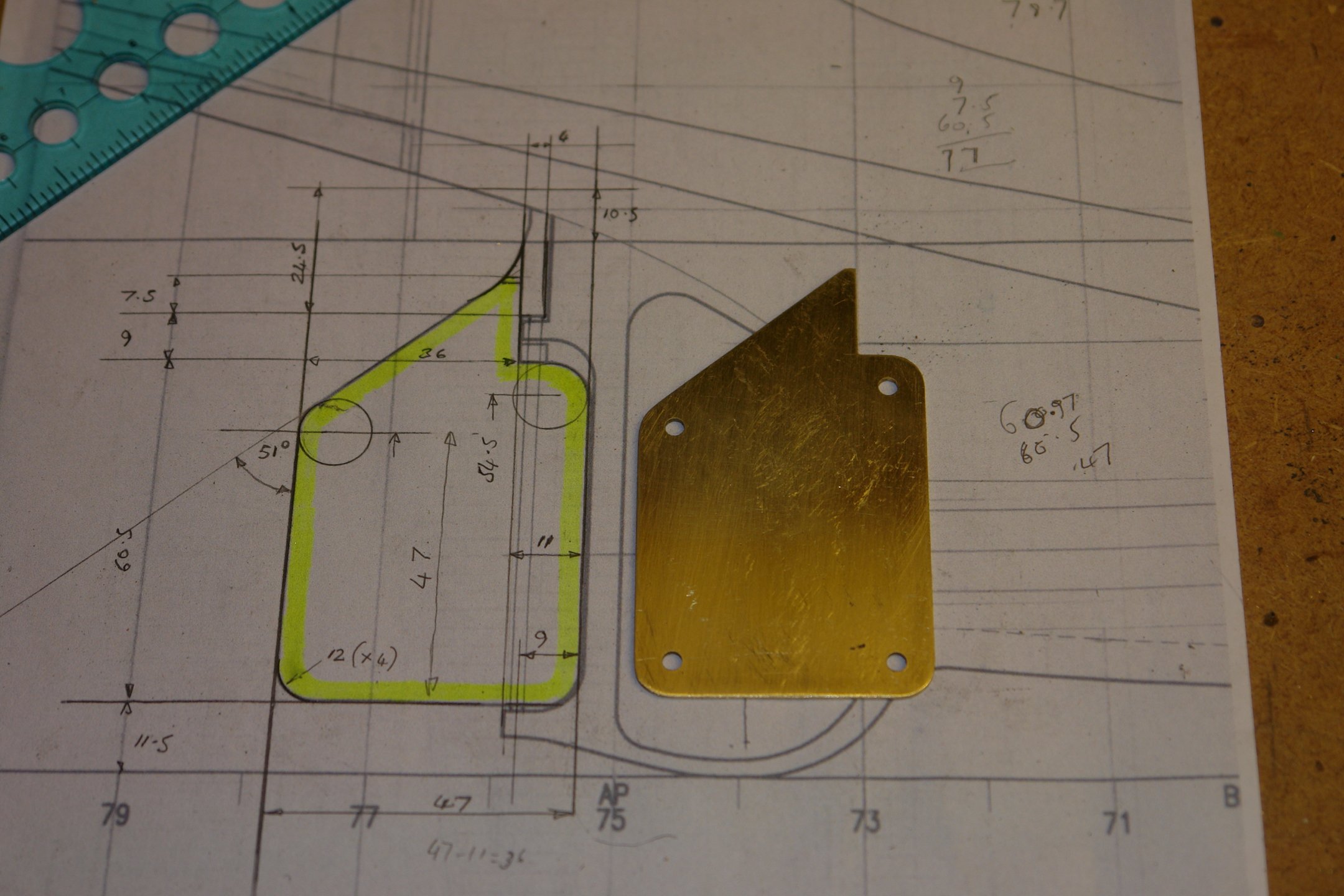
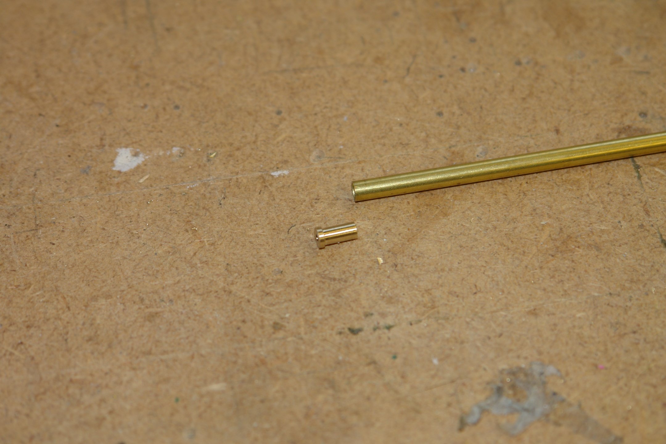
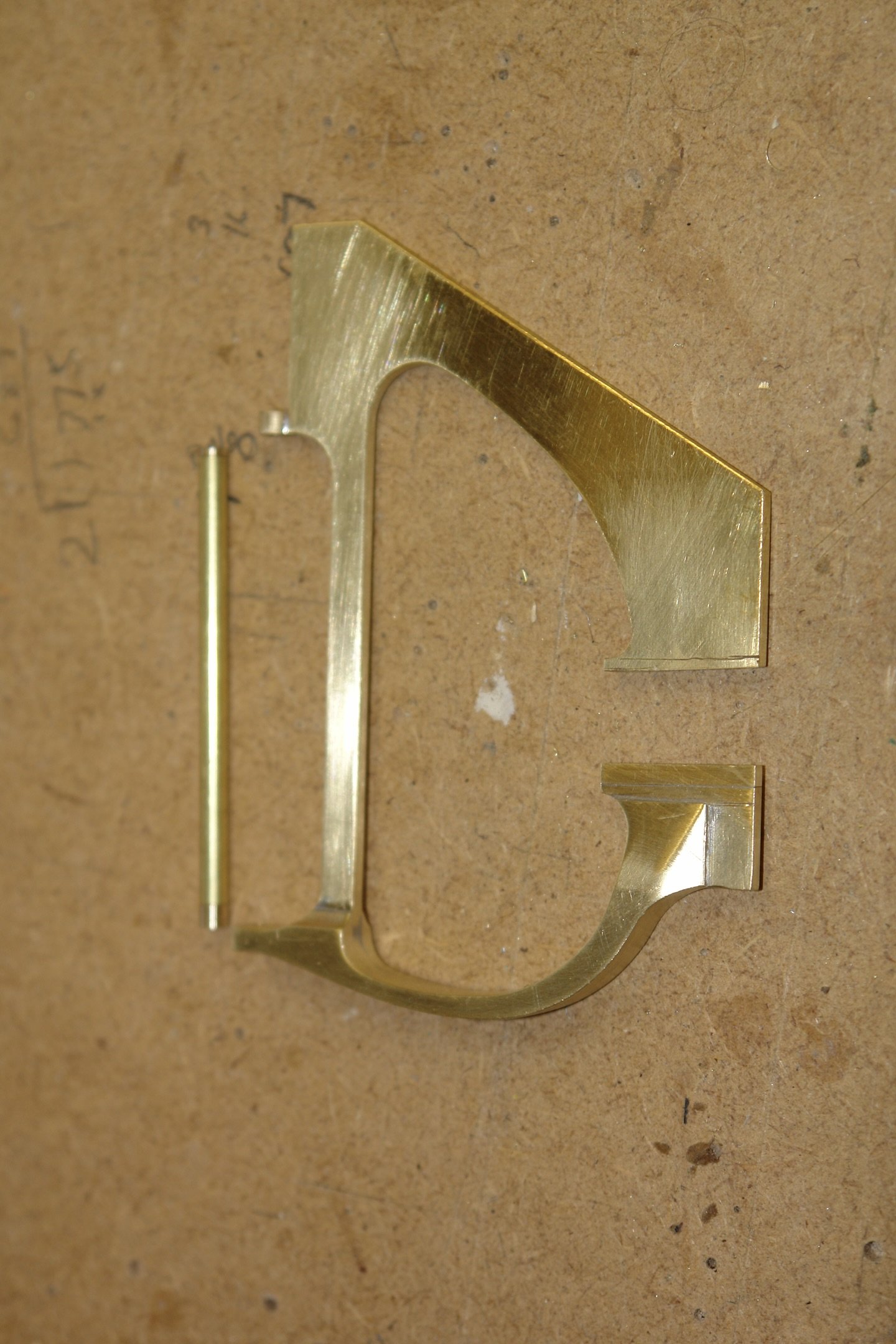
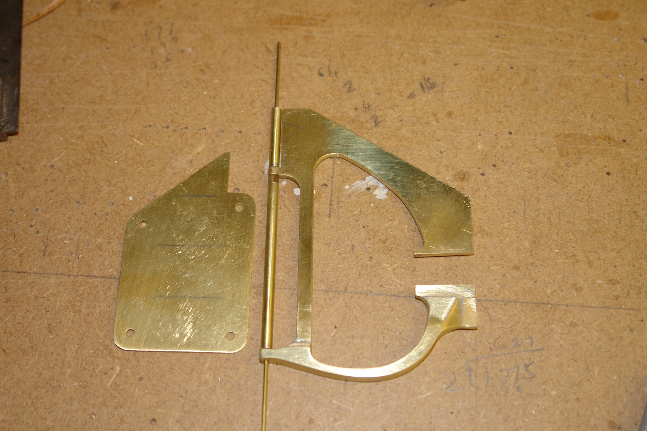
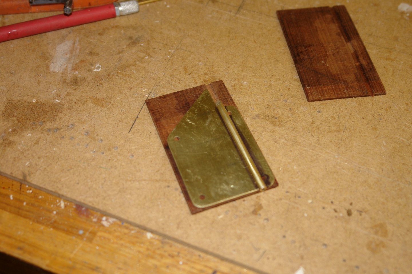
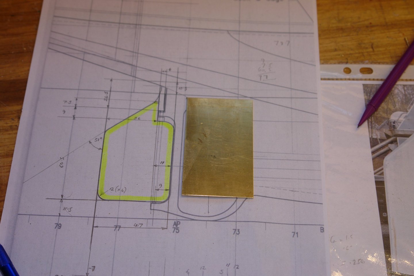
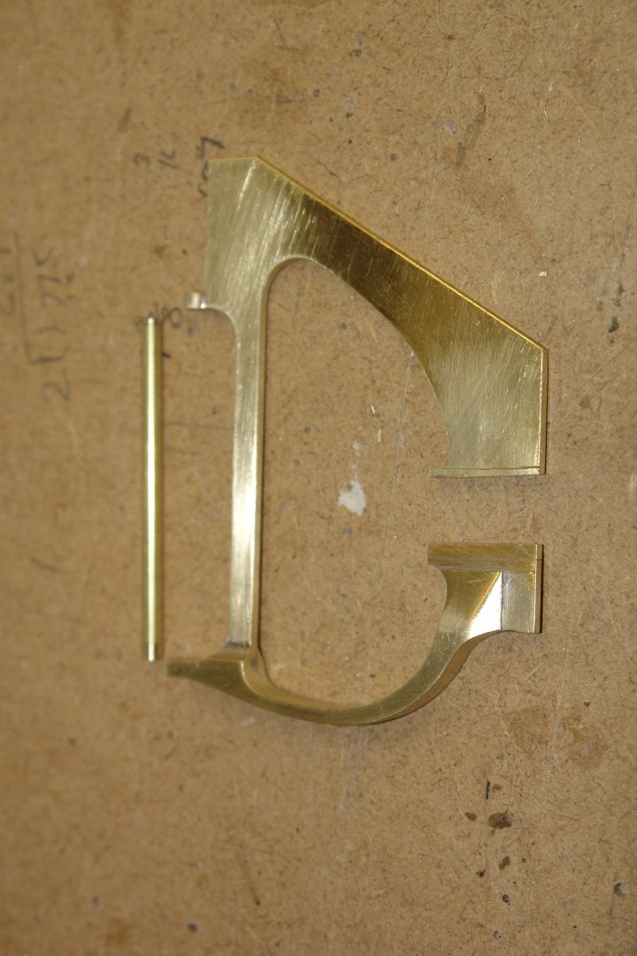
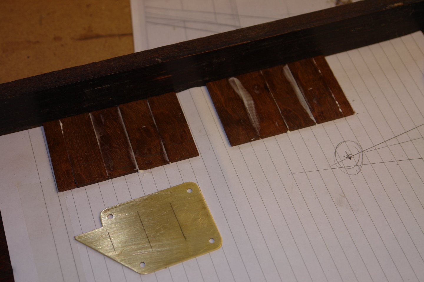
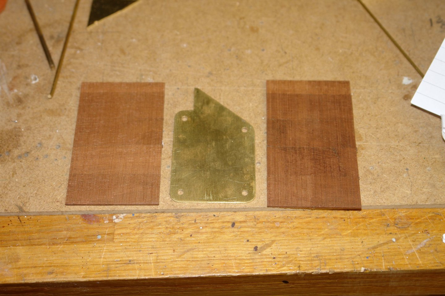
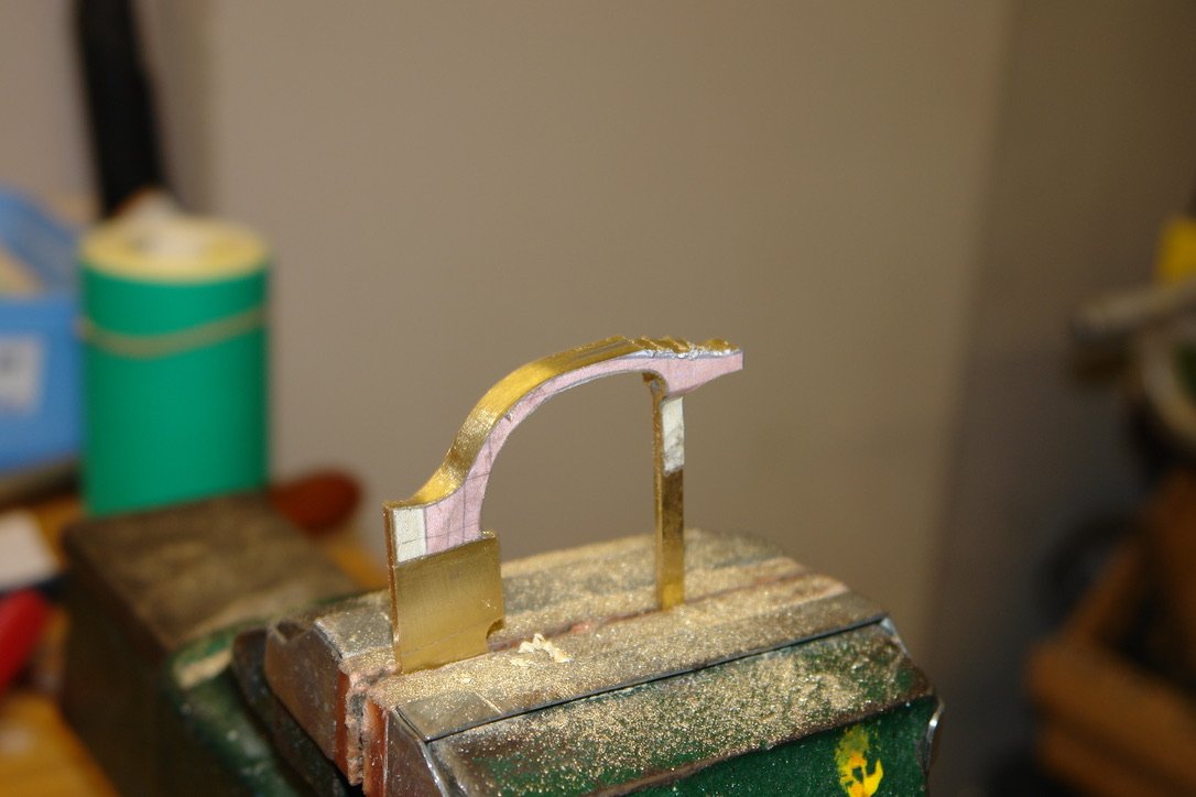
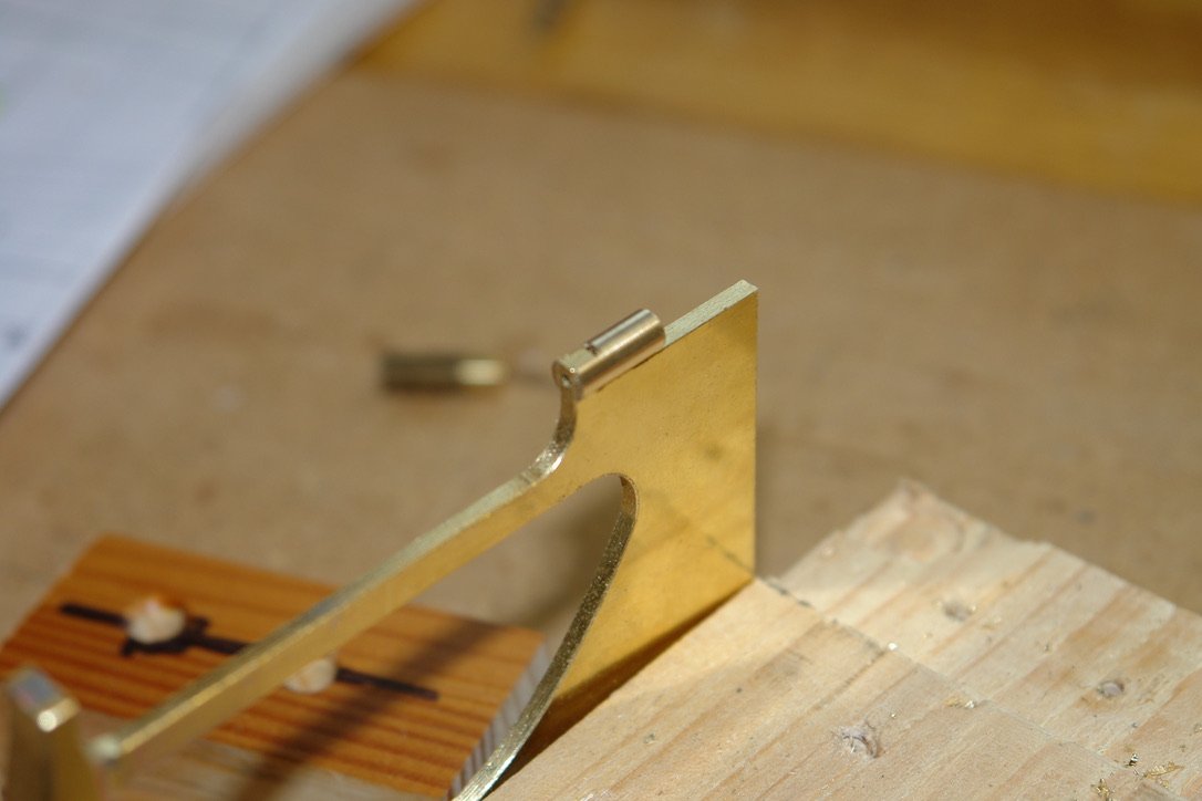
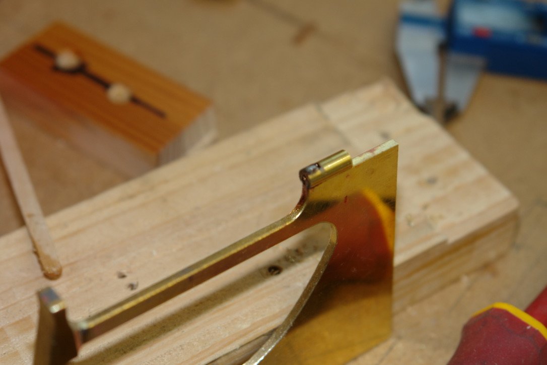
Thank you Richard and Pat. Gary - She says it is her greatest pleasure to be my forever financial burden. She also says my efforts are earning points which will influence her when choosing the quality of retirement home she will be putting me into when I can no longer look after myself. And so on to the rudder. I started with a brass sheet .040" thick. I drilled a number of holes at the centre of the various edge curves. I also turned up some filing buttons - blue arrows. I cut away the waste brass and using the buttons I filed the edge curves. The rudder is profiled / streamlined although the front and rear edges are blunt. The outer rudder shaft was made from brass tube with bearing ferrules at the upper and lower ends. The ferrules are drilled .040" diameter to take the fixed inner bearing shaft. The small upper section shaft was made in a similar way. Below all 3 parts are assembled. I will form the outer shape of the rudder by attaching mahogany to each side and then sanding to shape. Below the mahogany "cladding" has been cut and glued prior to attaching to the rudder shaft. That's all for now.


-
Eberhard - that was my worry and I also thought the method I chose was potentially the easiest to guarantee alignment between the upper and lower bearing holes. Tom - relatively cheap from Amazon or Ebay. And yes they are excellent for waterlines. Thank you Eberhard, Tom, Druxey, Rick, John and Nils. And thank you to the usual crew of followers for the likes.
-
I find that the older I feel the Dozier I get, and I can't even blame it on late nights. Remember every failure is an opportunity for improvement.😀
- 88 replies
-
- 4
-
-
- Vigilance
- Sailing Trawler
- (and 1 more)
-
That's the problem with natural products - they tend to be quite variable. It seemed to workout quite well.
-
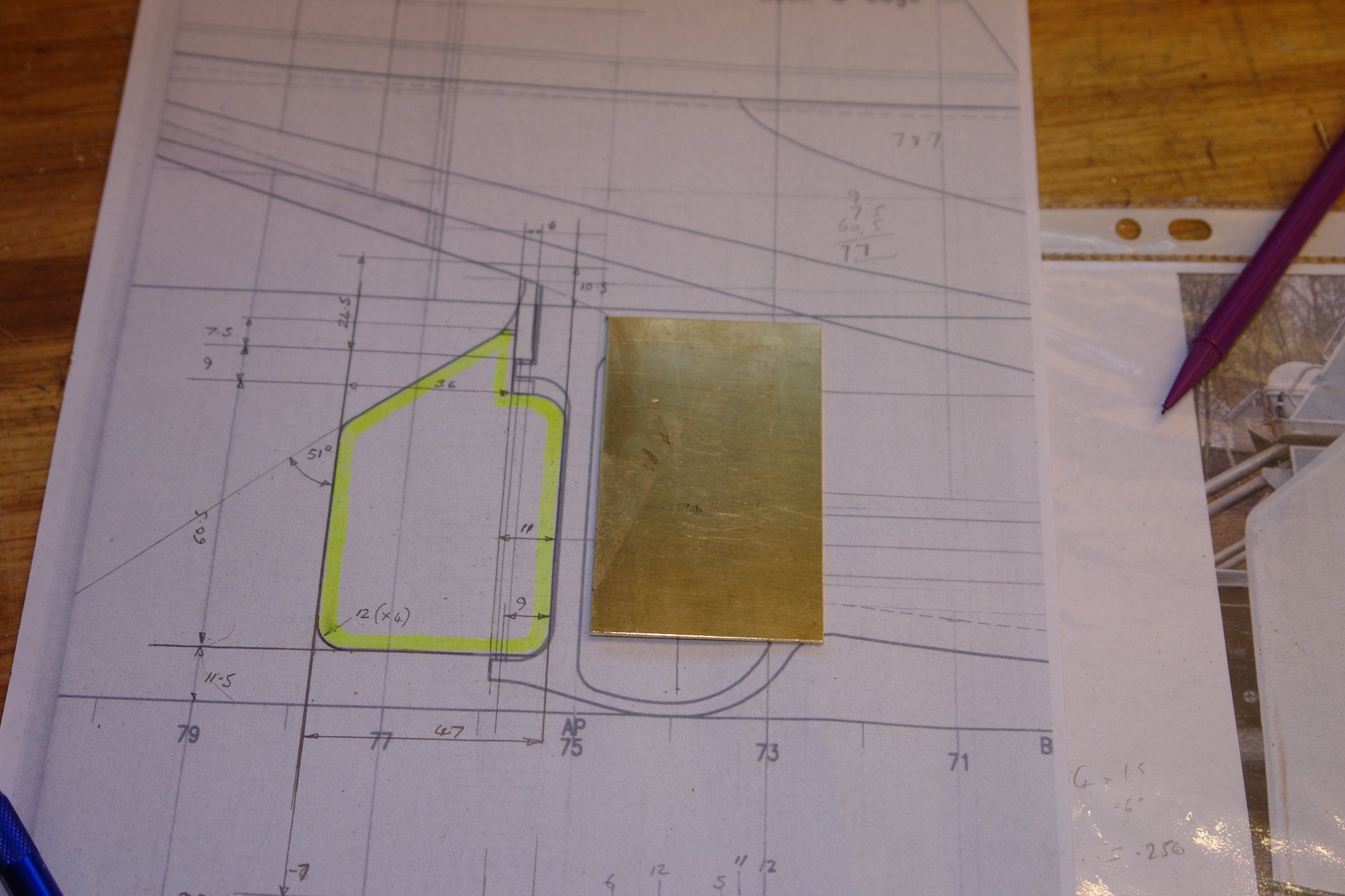
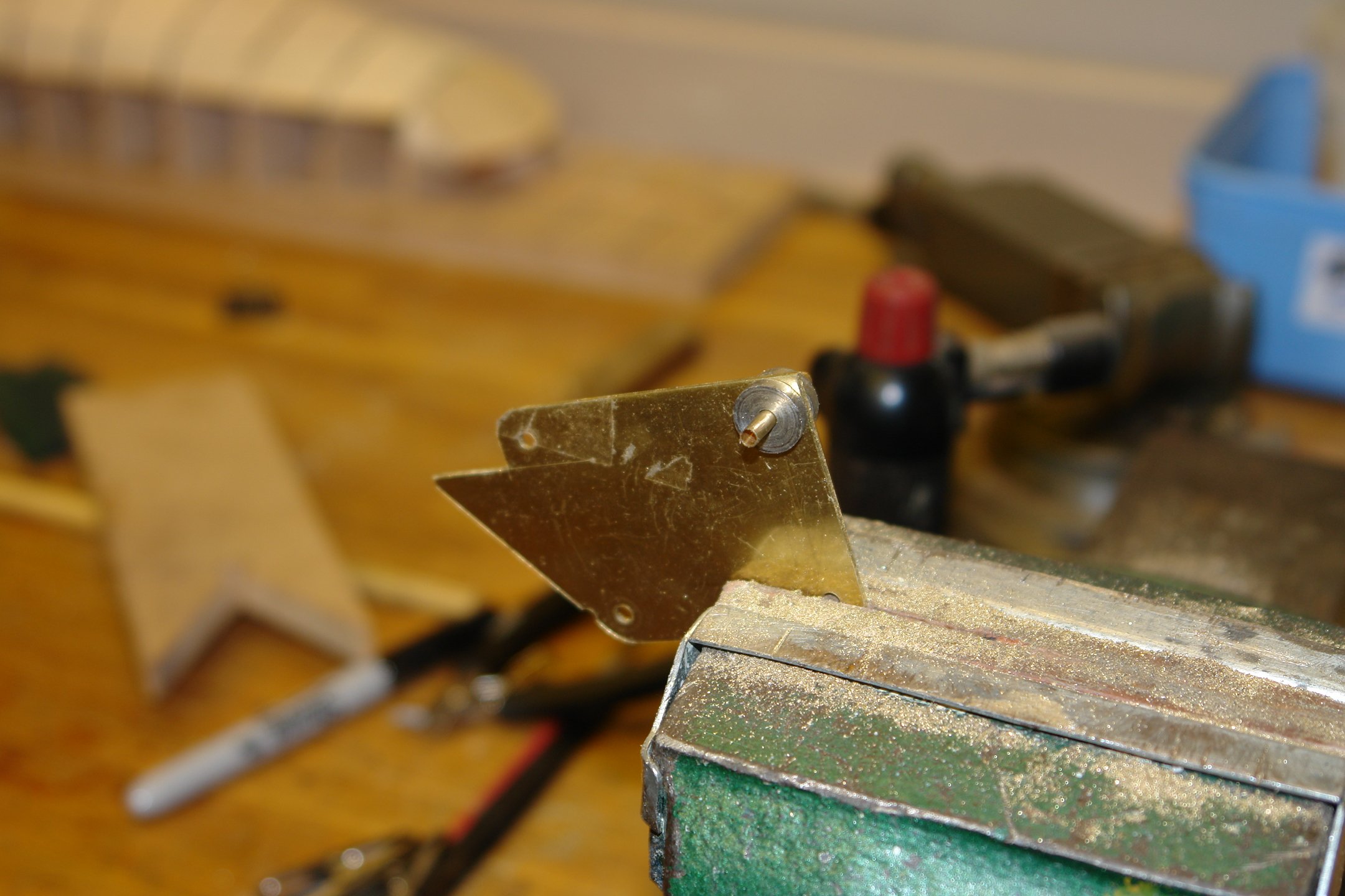
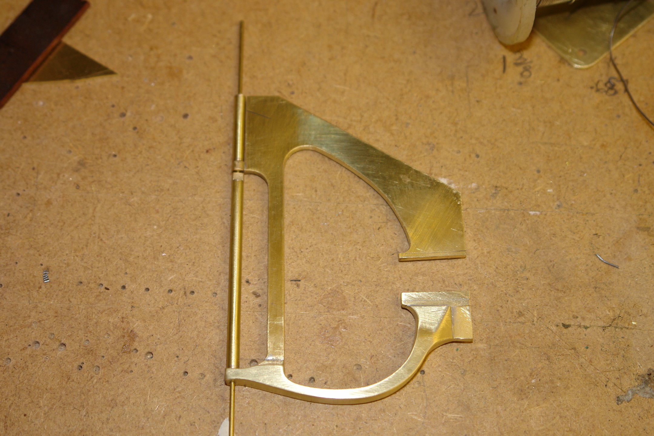
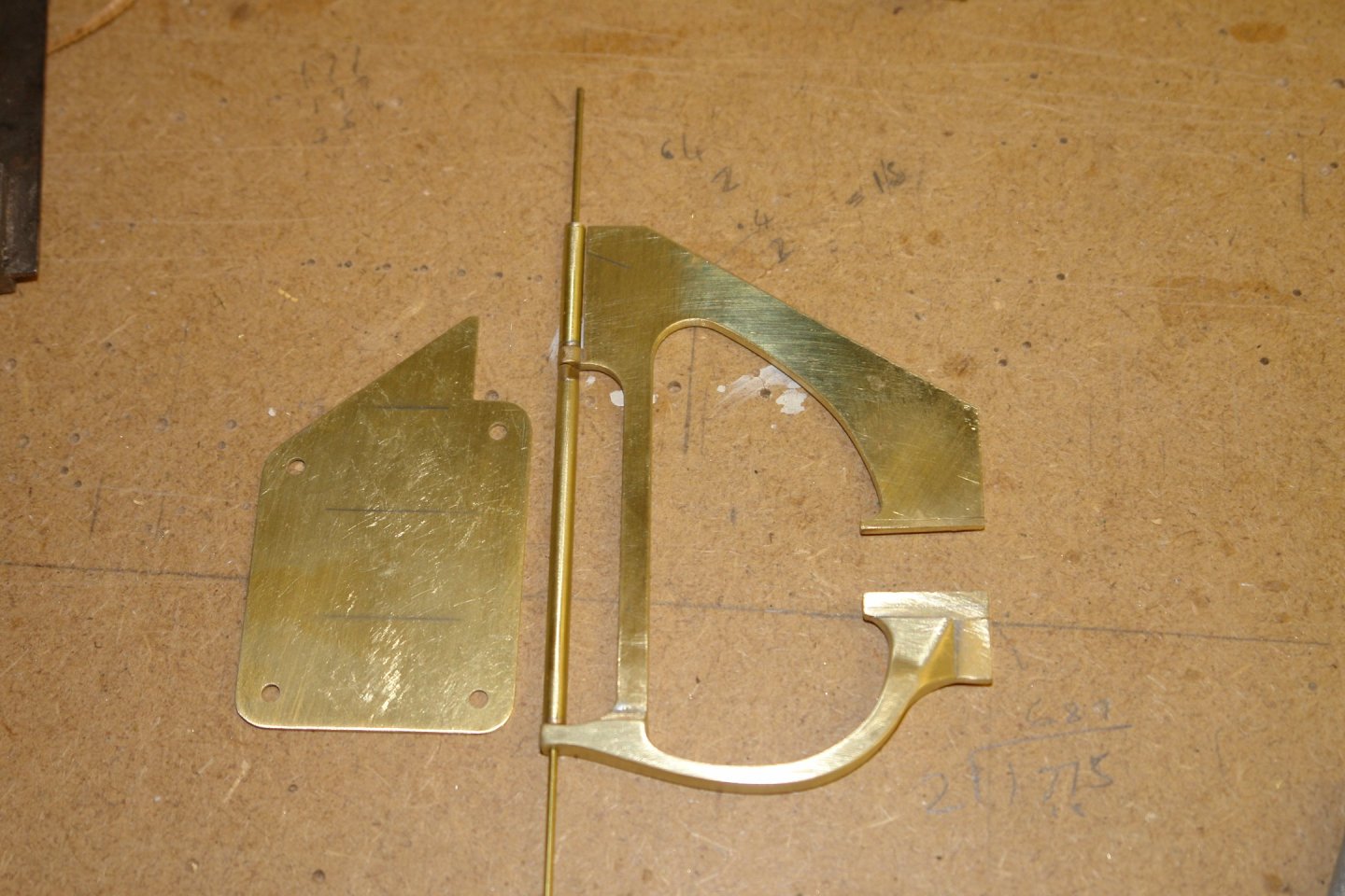
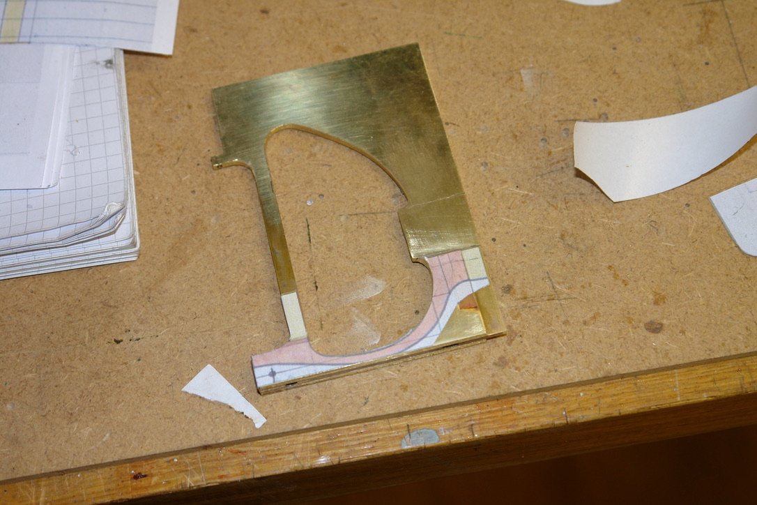
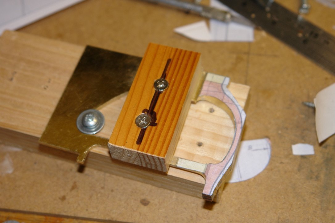
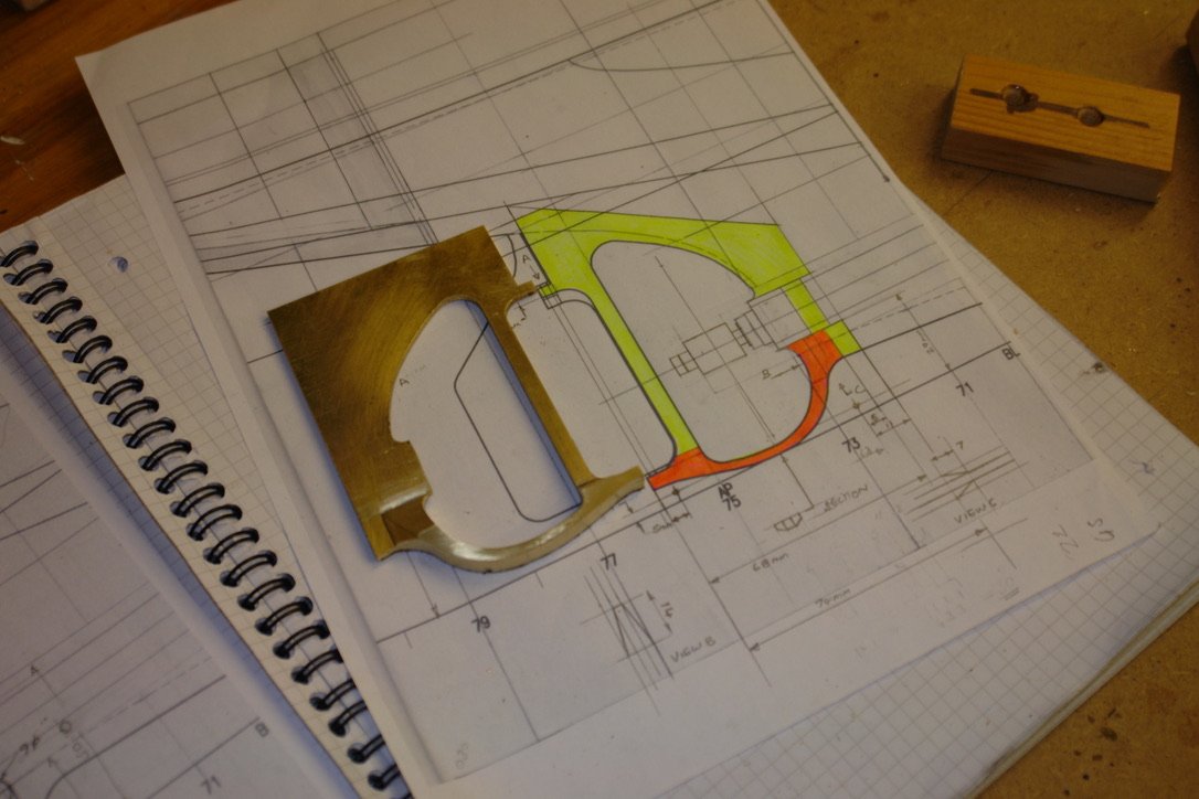
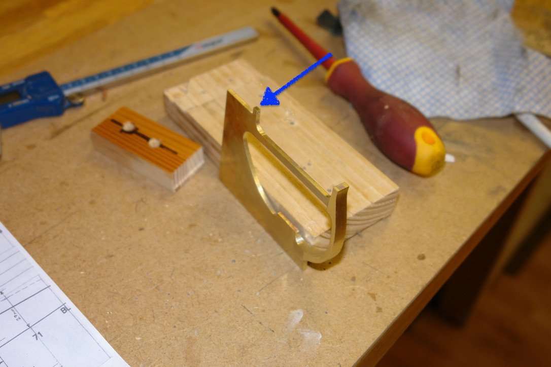
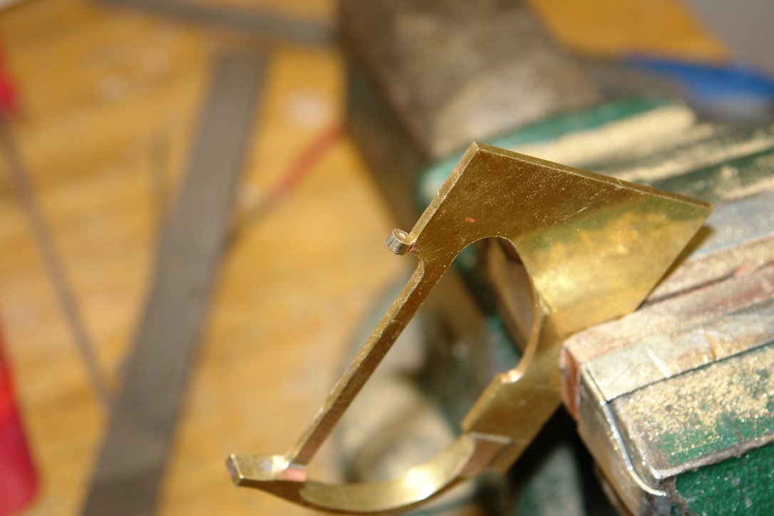
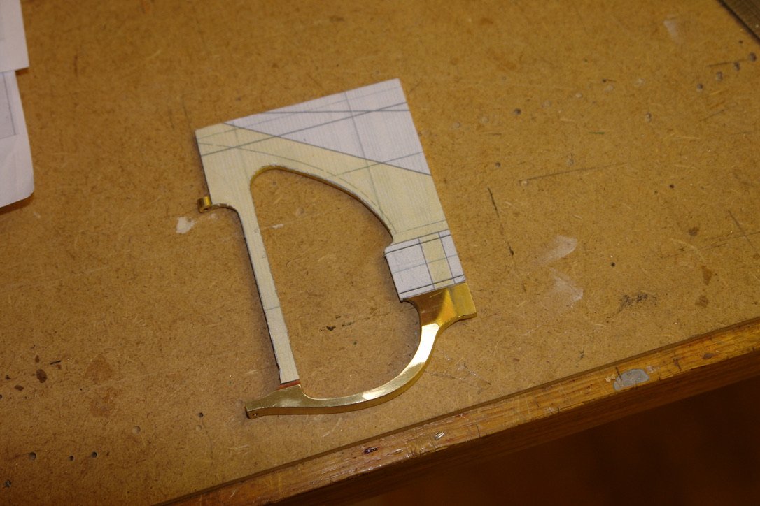
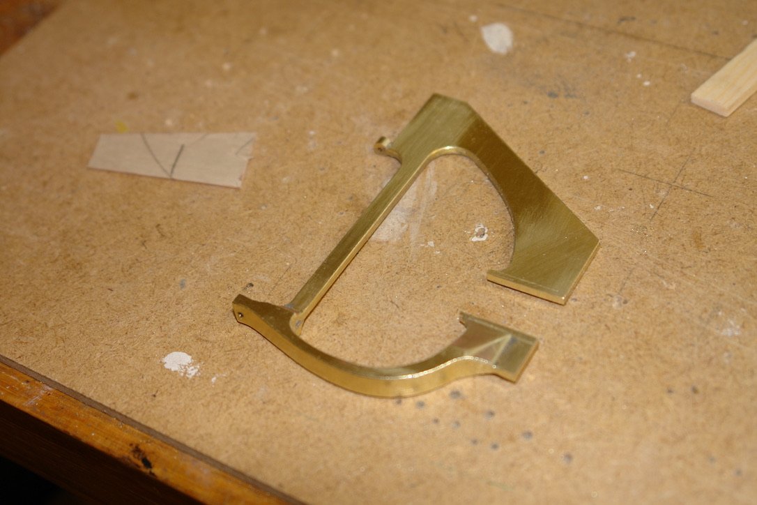
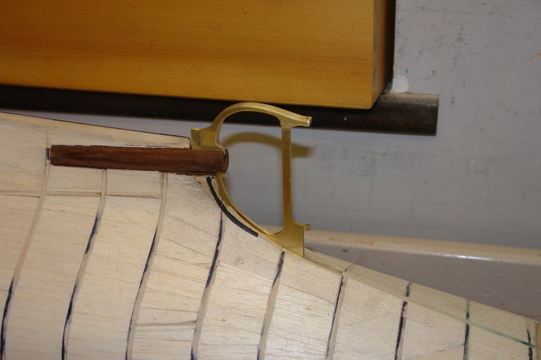
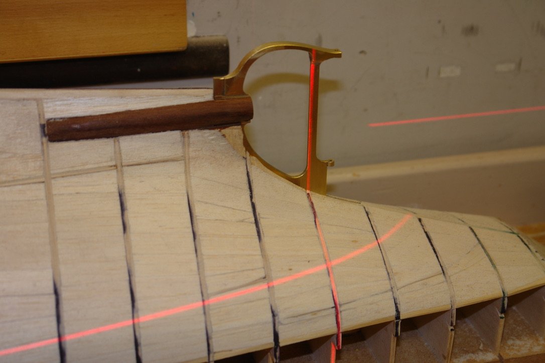
A little more progress on the rudder frame. Thank you Rick / Richard - Exactly so Richard. I am still using paper templates to get the shapes right. The wedge angles produce a little distortion in the templates but nothing worth worrying about. I cut the bulk of the excess metal away with straight cuts using my hacksaw. I then clamped the frame to a piece of wood for a bit of milling. I nibbled my way towards the desired profile using an end mill cutting vertically. I then blended the frame to shape with various files. I also drilled holes (upper and lower) to take the rudder shaft. The frame around the upper rudder bearing is round and not square as currently formed. So I needed to form the 4mm diameter round boss. I did this by first slotting out the end of a piece of 4mm diameter rod. This was then placed over square section nib and soldered in place. The excess was then cut away and the boss was cleaned up with a file. Finally a paper template was used again prior to cutting away the waste. The frame was then test fitted into the pre made slot in the hull. Although not fixed in position I checked the alignment with a laser level. The frame isn't finished as it needs a fair bit of polishing with wet and dry paper before finishing on the polishing wheel. Next the rudder.
-
Not withstanding your trials and tribulations the hull painting turned out remarkably well. The red waterline is particularly crisp.
-
Beautifully neat work Valeriy.
-
Thank you for the tip. I'd better stock up before they ruin them. like Colron wood dye and Nitromors paint stripper.