CDR_Ret
-
Posts
545 -
Joined
-
Last visited
Content Type
Profiles
Forums
Gallery
Events
Everything posted by CDR_Ret
-

Ship Ribbing with CAD?
CDR_Ret replied to Sanjith_D's topic in CAD and 3D Modelling/Drafting Plans with Software
I would recommend checking out this thread regarding laser-cut frames, etc. Kiyoo Iizawa was actively involved in this forum a few years ago and did some beautiful work using CG modeling and laser-cut components. He was writing a manual/book to help modelers get into laser-cutting modeling, but after some attempts at collaboration, I think there was an (amicable) divergence of views on how to present the process. Terry -
Ship Ribbing with CAD?
CDR_Ret replied to Sanjith_D's topic in CAD and 3D Modelling/Drafting Plans with Software
IMHO, going directly from existing drawings to code that drives a 2D laser cutter is risky when cutting out frames or bulkheads. I have no experience with the quality of plans from the big national museums and other credible sources, but when I manually compared the body and halfbreadth plans of my 1891 brigantine project, it was an exercise in frustration. Heights and breadths of station and waterline intersections did not agree among the three views. The point I am trying to make is that there is no guarantee that using existing plans (especially if they are old, original drafts) will drive a laser cutter that will result in a smooth, fair, hull surface without a lot of extra work. The above observation was the reason I went to CG drafting in the first place. After nearly a decade of periodic frustration, trying different methods and different copies of plans from the Smithsonian and other museum/library archives, I found that using the DELFTship Free naval architecture software was pretty much ideal for fairing out the hull lines because it had the features needed to visualize the shape of the hull, remove low and high spots, and compare the resulting lines to the original drawings. The bottom line here is that obtaining a set of working plans that will actually be fair and eyepleasing in the real world won't necessarily yield the same set of station lines, waterlines, and buttock lines as in the original set of plans you obtained. It is up to you how far you are willing to deviate from the original drawings. There are a number of MSW members who have posted their projects using DELFTship Free, including my own. Comparison of the final modeled stations (green) in DELFTship Free compared to the original G.C. Berger drawing stations. Waterlines (blue) were included to ensure the correct vertical scale. To understand the genesis of these lines, please refer to the Galilee research log in my signature. (High-resolution plans obtained from the San Francisco Maritime National Historical Park Library; G.C. Berger, Pacific Marine Research Society; Date and provenance unknown.) Once you have what appears to be a valid set of lines to work with, then you can start thinking about what laser setup to use for cutting out your parts. Remember to cut to the outside-most of the front and back curves for each frame or bulkhead. Terry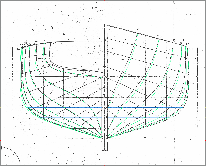
-
USF Confederacy in 3D | Blender
CDR_Ret replied to 3DShipWright's topic in CAD and 3D Modelling/Drafting Plans with Software
Beautiful, Nate! Terry -
3D Ropes/Rigging in Blender
CDR_Ret replied to 3DShipWright's topic in CAD and 3D Modelling/Drafting Plans with Software
So far, so good! -
Welcome aboard, Kevin! Yeah, the Lewis and Clark is nothing but HY-80 razor blades. There are quite a few (mostly former) bubbleheads as members here. Terry
-
Hey, Deyson. Another Coloradoan! Where are you located? I'm retired and living near grandchildren in the Springs. Great to have you aboard! Terry
-
Viriato. Eu sugiro usar o translate.yandex.com tradutor português / inglês. Isso parece fazer um trabalho muito preciso. (I suggest using the translate.yandex.com Portuguese/English translator. That seems to do a really accurate job.) Terry
-
Try reading it via the link on a mobile phone. Worked fine for me. Sad outcome.
-
My laser cut planks
CDR_Ret replied to modeller_masa's topic in Building, Framing, Planking and plating a ships hull and deck
You guys should work up a tutorial for developing laser patterns for things like cabin and roof planking, skylights, and other fine details. You might even start a small business of doing bespoke laser cutting jobs to pay for your hobby! Terry -
3D Brig 'Rose' in Blender 3.3x
CDR_Ret replied to 3DShipWright's topic in CAD and 3D Modelling/Drafting Plans with Software
Is there a simple way to add realistic crew in these renders? The main thing that indicates your image is artificial is the absence of any hands visible on deck, or at least at the wheel. Galilee had only eight assigned crewmembers (plus the five scientific expedition members), and all the photos of the ship at sea always had at least a few humans visible topside. Terry -
Most browsers have a feature to translate text to the user's default language. Looks pretty clear to me. Nice job on Bismark! Terry
-
A big miss in only 42 to 48 hours
CDR_Ret replied to DaveBaxt's topic in How to use the MSW forum - **NO MODELING CONTENT**
Not sure who to send this to, but I received this security message when I tried to access the site's article database: Probably not related to this weekend's mishap, but thought you should know. Terry
-
Where do you call home? I lived in Vermont several times in my life and consider the state my favorite. Lived in the greater Burlington area. I also drove LCT ferries to work my way through college (UVM). Best job ever! Terry
-
Looks like you are using Sketchup. Nicely done! Terry
-
3D Brig 'Rose' in Blender 3.3x
CDR_Ret replied to 3DShipWright's topic in CAD and 3D Modelling/Drafting Plans with Software
Beautiful work, Nate! -
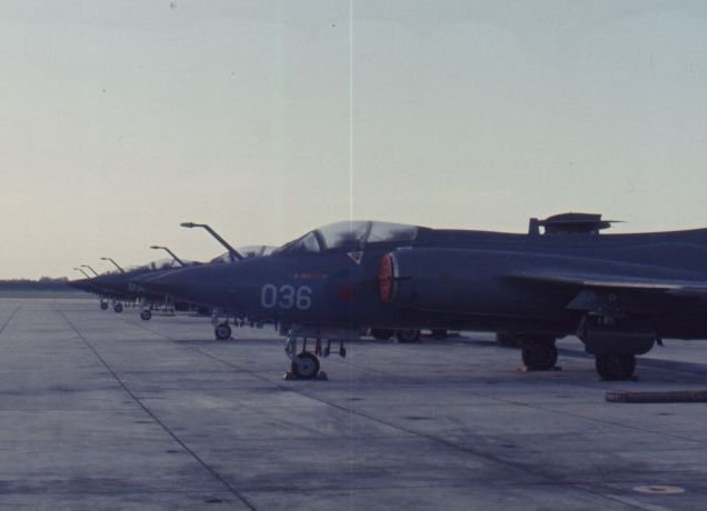
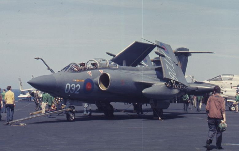
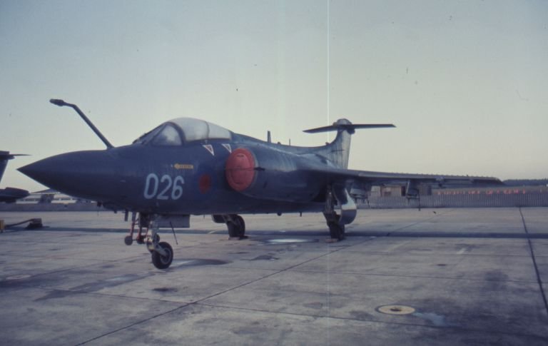
This topic reminded me of a joint US-UK naval exercise back in the Spring of 1975 that my squadron participated in. At that point I was a junior Naval Aviation Intelligence Officer assigned to an A-7E (Corsair II) squadron, VA-66, stationed at NAS Cecil Field in Pensacola, Florida. This was the year before I got my heart right and entered the Naval Nuclear Propulsion pipeline, and, ultimately, the submarine force. The exercise involved both the USS Independence (CV-62) and the HMS Ark Royal (R07) operating together in the West Atlantic. The Ark Royal cross-decked a squadron of Buccaneers to the Indy and the Indy cross-decked a squadron of Corsair IIs. This was evidently a prolonged collaboration because the photos of the aircraft taken at Cecil Field in my collection were dated March/April, 1975, while the shipboard photo was dated May, 1975. These photos were taken as Ektachrome slides, which were the thing back then. They're not great but they might be useful as a reference of operational aircraft. I failed to identify which squadron they belonged to but the date of deployment might narrow the choices. This final photo shows a Buccaneer on the USS Independence flight deck. Several A-7Es are in the background. Enjoy! Terry

-
For the casual visitor and ignorant ones like me, SIB = "ship in bottle". (I had to go look for this term to learn what it meant....) Terry
-
These are all good points to consider. The tarp in the DTM photo was put up when the weather was foul. To my untrained eye, though, the deck just doesn't look wet as much as having a gloss coat of paint. The finish is very uniform. Galilee's waterways and open bulwarks were definitely painted. One thing to remember is that during her charter period, she was classified as a yacht to avoid port fees, and DTM tried to gain public interest in the geomagnetic project by inviting the local populace onboard whenever ship was in port. So it might have been an exception to the rule regarding the finish of the decks. Galilee's weather deck in fair weather. I've treated the deck color the same as the coamings and waterways. (Courtesy Carnegie Science Library, c. 1906. All rights reserved.) As for lower maintenance, it might have been considered less maintenance to repaint the deck occasionally rather than replace or at least recaulk weathered planks. I apologize for hijacking the thread... I'll go back into my hole. P.S. In Crothers' The American Built Clipper Ship, p. 346, he states under "Deck and Deck Structures," in part, "...No paint was applied to deck surfaces. The raw wood was kept clean by constant scrubbing and mopping... Preservation was achieved by an occasional application of oil to repel water." So that may be the source of the sheen in photographs. Terry
-
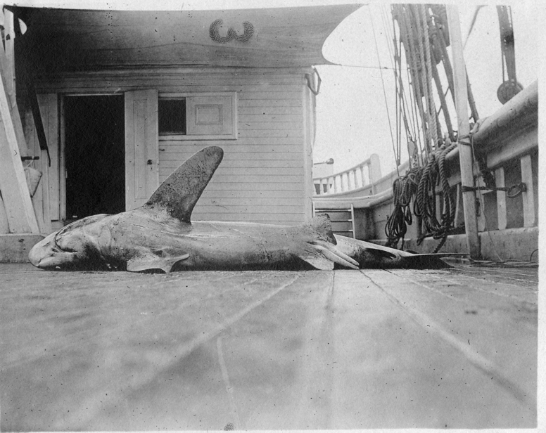
@druxey, would this statement have been true for all eras and applications? I understand that sailing warships had holystoned decks, but sailing merchants, particularly in the latter days of sail, had relatively small crews, which would have made routine deck maintenance difficult. I have some really good photos of the Galilee (1891 brigantine, crew of 11) taken in the early 1900s, and her deck definitely looks painted to me. Photo of a shark caught by the ship's crew of Galilee during her DTM Cruise II in the Pacific Ocean. (Courtesy Carnegie Science Library, c. 1906. All rights reserved.) Terry
-
Thanks @BANYAN. I've spent so much time immersed in developing the structure of the ship over the past seven years that I'm only now beginning to look at the rigging and related securements in any detail. And I'm not well versed in the jargon associated with masting and rigging, so what you quoted is mostly gibberish to me. A lot of catch-up will be required before drafting up the plans! Appreciate your efforts. Terry
-
What's easier?
CDR_Ret replied to Srenner's topic in CAD and 3D Modelling/Drafting Plans with Software
Hi Srenner, You may want to DM the other Blender users in this forum such as @Kurtis and @3DShipWright with your question. I'm afraid that the answer to your question is well above most of our paygrades! Terry -
Back in the days of "useta-fish" (US attack submarines were named after sea creatures until they started naming them after random congressmen, then cities. "Fish don't vote!"—Adm. Rickover), we typically stood one-in-three, six-hour watches underway. Generally, attack boats (SSNs) were able to keep their watchbills manned with qualified watchstanders because we did frequent local ops when not deployed. I don't ever recall a dog watch in an SSN because the watches rotated through the 24-hour cycle and everyone could get at least six hours of sleep per day. Boomer crews, on the other hand, arrived at the turnover site with a large portion of the crew either provisionally qualified on their watch stations—or not at all. This was because, for the Offcrew period, we had no boat, and personnel transfers occurred during Offcrew. For the first month or so on patrol, there were a lot of port-and-starboard (we called it "port-and-stupid") watches. After four months at sea on a Westpac in USS Hawkbill, nearly everyone was qualified to their most senior watch stations, so we were able to go to one-in-four watches for the crew and the officers were one-in-six. As Senior Watch Officer, I even let the Engineer off the watchbill completely because he had an ORSE (Operational Reactor Safeguards Examination) to prepare for on the way back to Hawaii after that deployment. I have no idea what modern submarines do. It's been more than 30 years since I've been on a boat...
-
3D Brig 'Rose' in Blender 3.3x
CDR_Ret replied to 3DShipWright's topic in CAD and 3D Modelling/Drafting Plans with Software
Very nice job! Nice rendering of the skins, which took a lot of work. I feel your pain... Terry -
Any Delftship users here?
CDR_Ret replied to Patrick Matthews's topic in CAD and 3D Modelling/Drafting Plans with Software
Very nice, Pat! I built Revell's model of the Fire Fighter as a kid. I have no idea how accurate that was. Anyway, it seems that trying to export files out of DELFTship will be problematic. And after trying to export DXF 3D geometry into 3rd-party file converters this weekend, it almost looks like the function is broken in the Free version. I only get the crease edges. No surfaces at all. -
Any Delftship users here?
CDR_Ret replied to Patrick Matthews's topic in CAD and 3D Modelling/Drafting Plans with Software
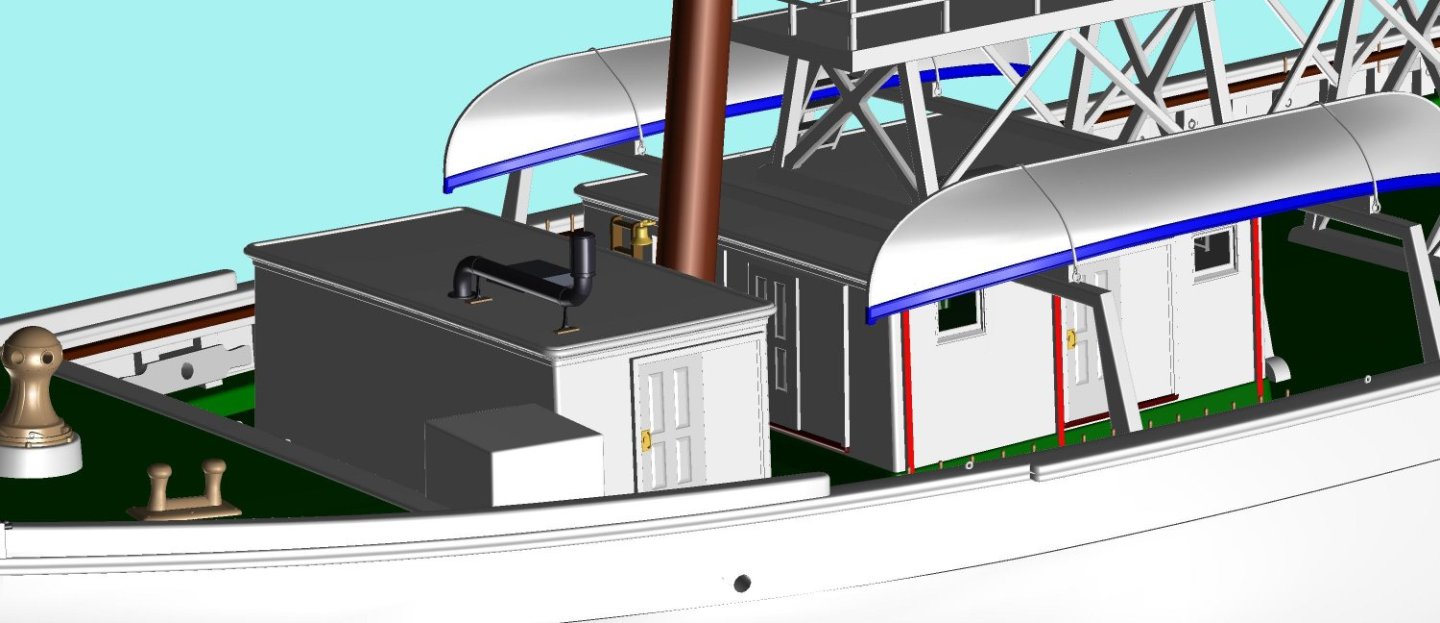
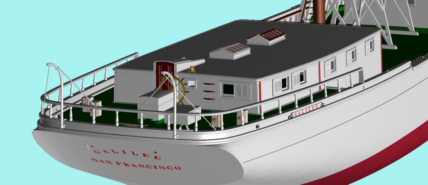
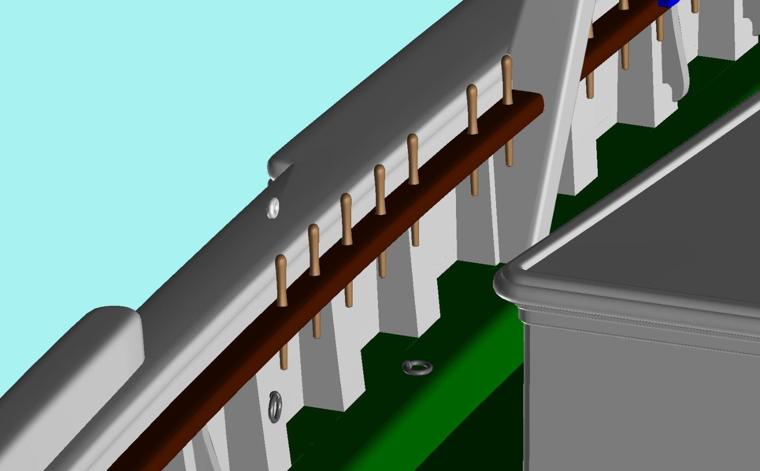
Pat, I guess I must have worded my question wrong, or at least it was unclear. Sorry about that. Ultimately, do you want to create 2D lines plans or produce files that can be 3D printed? If the former, then DELFTship Free has everything you will need for lines plans. You can create stations, waterlines, buttocks, and diagonals at any spacing you wish, The Control Net can produce as smooth a surface as desired and the surface tools can identify surface irregularities, as you mentioned in an earlier post. The choice of dimensional precision permits you to create very tiny and precise objects as well. My brigantine model has objects that are accurately dimensioned down to small fractions of an inch, though one would never be able to model those in the real world at a reasonable scale. Here are several views of Galilee in DELFTship Free showing the details possible. Exported images here are rendered within DELFTship at originally 3000 px wide. The only details I omitted in the model were the beaded sheathing planks on the cabin sides simply because that would have been too tedious for what you would get out of the work. Forward deck area of the brigantine Galilee as she was in 1907 while under charter to the Department of Terrestrial Magnetism, Carnegie Institution, Washington, D.C. Modeled in DELFTship Free. Galilee aft view. Modeled in DELFTship Free. The outboard rods supporting the davits are 3/4-inch diameter by scale. Details of hardware in Galilee modeled in DELFTship Free. Belaying pins, eyebolts, ring bolts, all were created to scale. 2D lines plans can be produced right within the program, suitable for desktop or roll printers. To reduce the clutter, you have to select only the layers intended to be printed in the Lines Plans via the Edit menu of the Layers group in the Home Ribbon. The major downside to DELFTship is that you can't produce photorealistic images of the model which might be useful for a client. Also, DELFTship does not have a lot of tools for modeling small detailed objects that other programs like Fusion360, FreeCAD, Blender, or Sketchup may have. But with patience and ingenuity, you can create just about anything. I haven't tried anything organic yet, but others have. Is this what you are trying to achieve? Terry