glennreader
-
Posts
136 -
Joined
-
Last visited
Recent Profile Visitors
1,530 profile views


-
 Zocane reacted to a post in a topic:
Scottish Maid by glennreader – Artesania Latina – Scale 1/64
Zocane reacted to a post in a topic:
Scottish Maid by glennreader – Artesania Latina – Scale 1/64
-
Karin Bartels reacted to a post in a topic:
L’Etoile by glennreader - FINISHED - Billing Boats - Scale 1:50 - Updated to represent her current fitting out
-
Bill Morrison reacted to a post in a topic:
Constitution by jfinan - FINISHED - BlueJacket Shipcrafters
-
egkb reacted to a post in a topic:
Schooner Sunset by Douglas Bennet
-
Larry Cowden reacted to a post in a topic:
USRC Ranger 1819 by Cathead – FINISHED – Corel – Scale 1:64
-
Larry Cowden reacted to a post in a topic:
Scottish Maid by Tim Curtis - FINISHED - Artesania Latina - Scale 1:50
-
Rik Thistle reacted to a post in a topic:
Scottish Maid by glennreader – Artesania Latina – Scale 1/64
-
yvesvidal reacted to a post in a topic:
L’Etoile by glennreader - FINISHED - Billing Boats - Scale 1:50 - Updated to represent her current fitting out
-
yvesvidal reacted to a post in a topic:
L’Etoile by glennreader - FINISHED - Billing Boats - Scale 1:50 - Updated to represent her current fitting out
-
yvesvidal reacted to a post in a topic:
L’Etoile by glennreader - FINISHED - Billing Boats - Scale 1:50 - Updated to represent her current fitting out
-
 Hello, I log in for the first time In 6 months (has it really been that long) and find a couple of recent messages, coincidence! I have been very busy with other things (gardening, decorating, …) and it does not look like there will be any let up until the new year, at the earliest. Everything is put away in boxes. Yes, I was really annoyed about the scale of the kit. Before purchasing (by mail order) I thought it might be out by a small amount, but when I realised it was out by so much and effectively they were just lying about the scale I was really annoyed. They cannot be ignorant of the fact. What I do not understand is why do they do it. I would not think it would make much if any difference to their sales to market it as 1/64 instead of 1/50. I thought long and hard before deciding to continue and build the model. Especially as I had always meant to go my own way with regard to decoration, sail plan and rigging. The kit is very much based on the drawing of the ship in dock being unloaded, which is totally conjectural. I had planned on displaying it alongside the Etoile, both at the same scale, almost the same size. to show the development of that type of ship in the relatively short period between there construction. But alas not possible now. I am tempted to linger and have a look at other projects I was following, but alas time calls. Look forward to getting back to work on the model. Keeps me going through all those jobs in the garden (I am the landscaper my wife is the gardener). Glenn
 -
glennreader reacted to a post in a topic:
Armed Virginia Sloop By captain_hook - FINISHED - Model Shipways - Scale 1:48
-
glennreader reacted to a post in a topic:
HM Cutter Cheerful 1806 by Blue Ensign - FINISHED - Syren Ship Model Company - 1:48 scale
-
glennreader reacted to a post in a topic:
Amerigo Vespucci 1931 by schiffebastler - Mantua - scale 1:84 - Italian sail training ship build
-
glennreader reacted to a post in a topic:
US Brig Syren by Rustyj - 1:64 - Rigging Redo
-
glennreader reacted to a post in a topic:
Willie L Bennett by Griphos - Model Shipways - Scale 1:32 - Skipjack
-
glennreader reacted to a post in a topic:
Willie L Bennett by Griphos - Model Shipways - Scale 1:32 - Skipjack
-
glennreader reacted to a post in a topic:
Willie L Bennett by Griphos - Model Shipways - Scale 1:32 - Skipjack
-
glennreader reacted to a post in a topic:
Willie L Bennett by Griphos - Model Shipways - Scale 1:32 - Skipjack
-
glennreader reacted to a post in a topic:
HMS Royal Caroline by Peta_V - Panart - scale 1/47 - from box with modifications
-
glennreader reacted to a post in a topic:
Brig Niagara by ronkamin - Model Shipways - 1/64
-
Joachim, Thanks for clarifying the size of the eyelets, though the ones along the head still look smaller than 0.6mm. I have to say that I do not think that I have ever seen sails made to such a level of detail and at 1/84 scale. It makes me wonder how you would do furled sails. I think sails are one of the most challenging parts of any ship model. Glenn
-
Joachim. The detail on these sails is just amazing. Neve seen any sails like them. Are you making the grommets from brass tube? What size? Stunned. Glenn
-
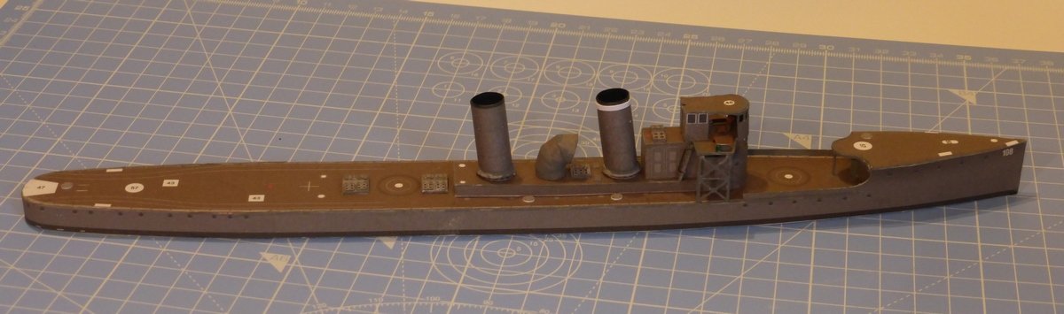
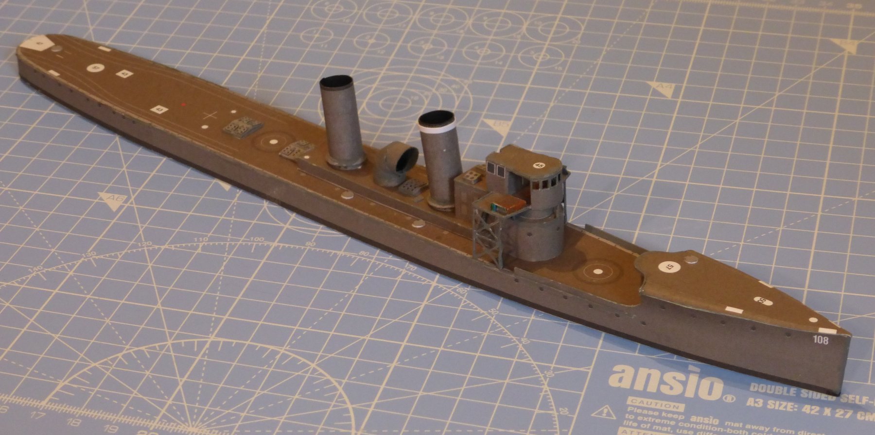
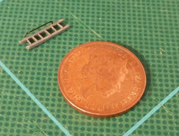
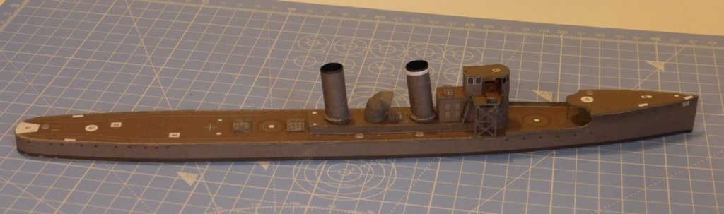
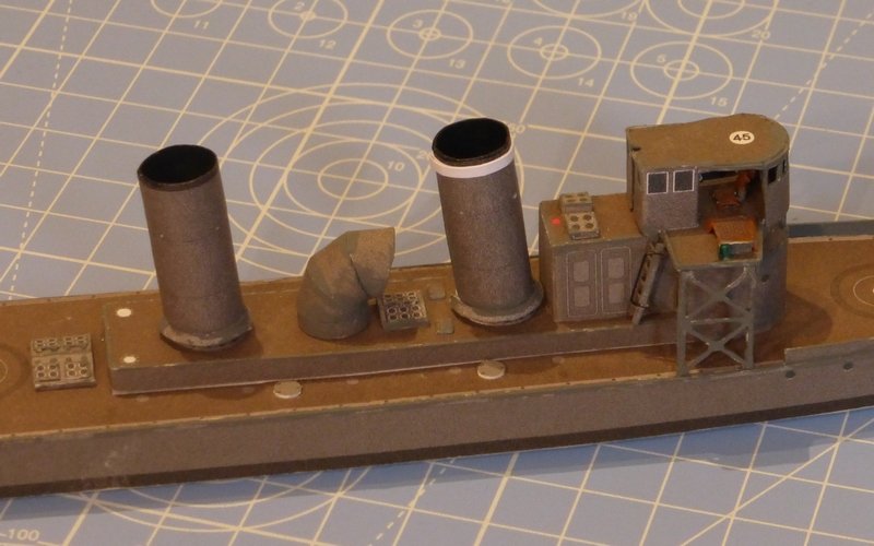
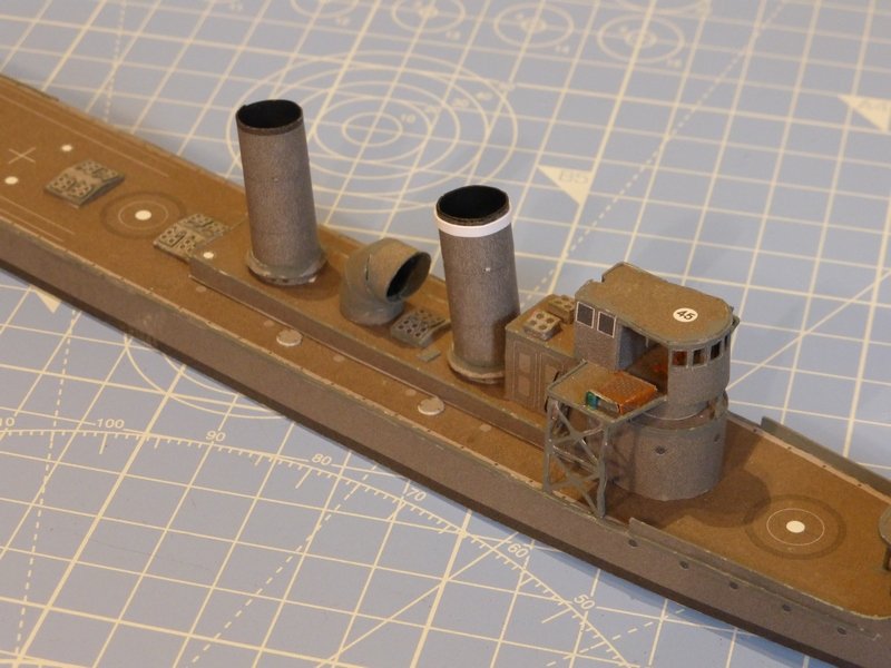
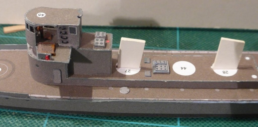
It has been sometime since I have had any time for hobbies. The sun came out and I was detailed for garden duties. However the weather has turned again and some spare time materialised. Not enough to do some work on the Scottish Maid but enough to set up a cutting mat on the dining room table. The first job was to finish cutting out and making the funnels. One came out slightly large and I had to leave a bit of excess on that conical bit at the bottom to make it stretch round. The main new technique here was rolling the funnels themselves. Using Chris’s tip of slightly damping the inside proved invaluable, but it did cause some problems with the card coming apart in layers. A very fine dividing line between the right amount of water and too much. Still I was quite happy with the results. Then came that large vent thing between. My first attempt was a bit of a flop, trying to glue the individual bits together. At one point I tried holding them together with Tamiya masking tape while the glue set, but that was a disaster. I discarded this and decided to try thinner material, as I had that printed out. This proved to be much too thin to glue edge to edge and that was also discarded. Finally I went back to my original very thick card pieces, which although they proved too thick for really sharp bends proved ideal for making into tubes and gluing edge to edge. So on my 3rd attempt at this part I finally had one that worked. I would put this down as the most difficult part I have yet made on this model. Then I made the ladder which gives access to the bridge. The steps were really tiny, maybe 1mm x2mm, but it all went together quite easily. Rather than try to make any sort of fancy jig to get everything right, at this scale I just eyeballed it. I then used some of the black beading wire I had to make a simple hand rail for the outside edge. I think that is part VI finished, I will leave the bridge railings till the end when I will do all the railings together. So next Part VII – The armament. Finally the mandatory pictures. I thought if I leave them all to the end I do not have to worry about what text goes which each picture. I also notice that I forgot to colour the edges of the fuel bunker hatches, oh well. Glenn

- 10 replies
-
- 3
-
-
- v108
- digital navy
- (and 1 more)
-
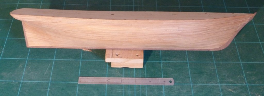
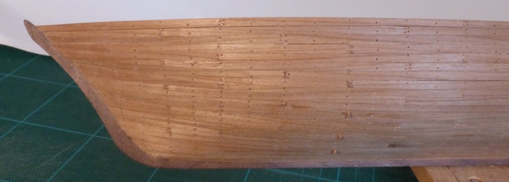
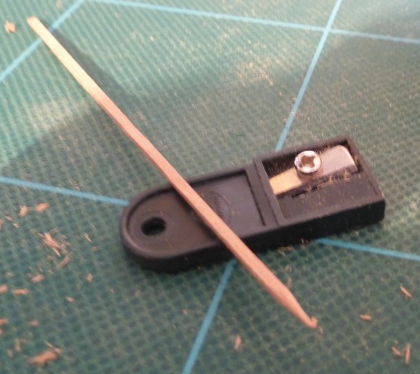
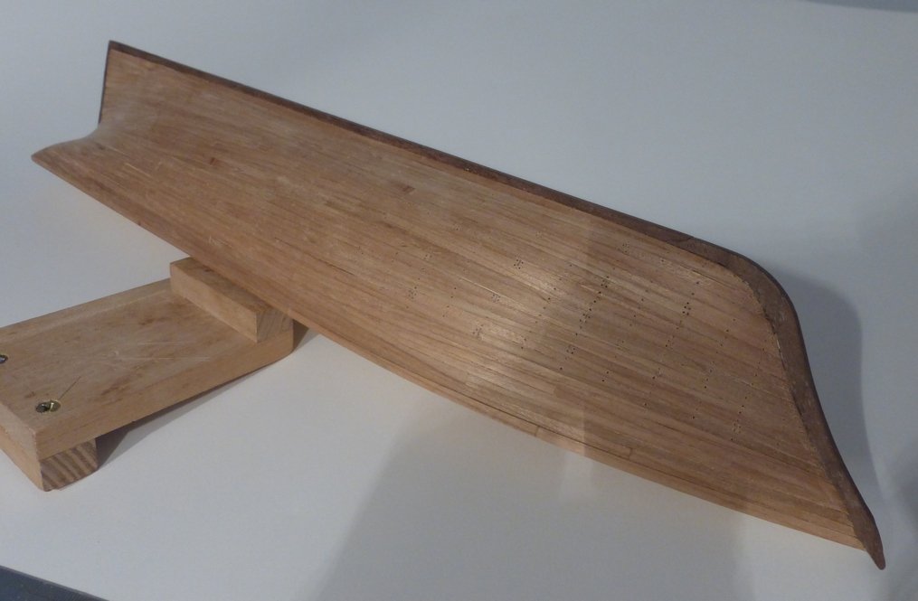
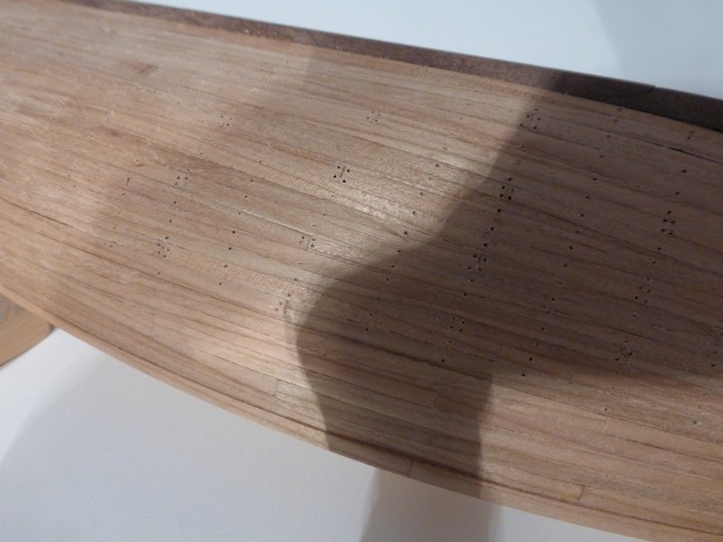
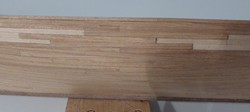
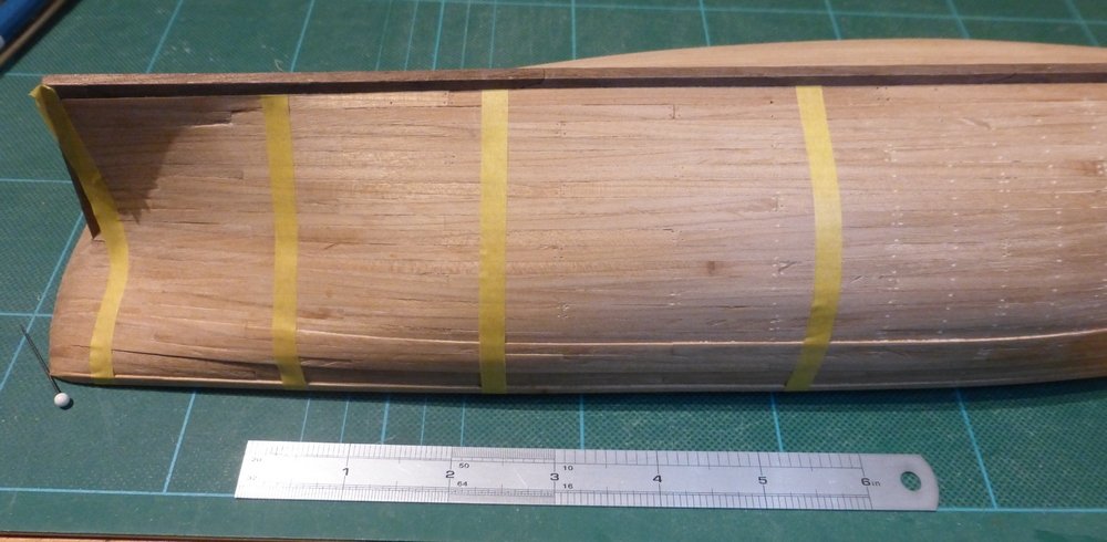
This is just a small update, because there has not been too much done since my last update. First, I have finished planking the second side of the hull up to the level of the false deck. I have finished the initial rough sanding but still need to work my way down through finer grades. I have done the tree nailing on about 1/3 of the first side. In the following picture you should be able to see one of the rows contains the ends of some tree nails sticking out. Those forward of that have been done and those aft are just holes. There are about 1060 to do each side. At the current rate that is about another 6-8 weeks work. I hope to find some more time to speed that up, it is not the most enjoyable of tasks. I managed to speed it up a bit when I realised I could use a sharpener for 2mm leads to make the points on the wood I am using for the tree nails, but I am still only getting about 50 done each session. Since I took the above picture I have done the next row of 23, which is all I have done so far today. While doing this I will also start to prepare the materials needed to plank the deck and make the bulwarks. The planking for the bulwarks will be from the same wood as the hull planking, bit it should be narrower and thinner. I have some lighter wood to use for the deck, I think it is Castillo Boxwood, but it is not too hand and I am not 100% certain. I will use some 1/8" basswood I have for the bulwark stanchions and the cover plank. Overall I am happy with the way this is turning out. I know the second side is turning out better than the first side, but I am using this project to try to do things I have not done before. I would be disappointed if the second side was not an improvement. This is also a reflection of the time I want to spend on this model, I look at this as a step forward not a life's work. That's all for now, might manage a few more tree nails before I call it a day. Glenn
-
L'Etoile by mhkash - FINISHED
glennreader replied to mhkash's topic in - Build logs for subjects built 1901 - Present Day
Hi mhkash, You are wrong, after building the L'Etoile Topsail schooners have become a firm favourite. I am now building another one The Scottish Maid. However I have possessed the kit for the Snake, a Sloop of War, for a number of years and will build that afterwards. Your model is coming along very nicely. Glenn -
L'Etoile by mhkash - FINISHED
glennreader replied to mhkash's topic in - Build logs for subjects built 1901 - Present Day
mhkash, You are progressing quickly. It looks more correct now you have the poop deck done. I am looking forward to seeing what you do. I had a look at your link to the model of CLAIRE. It does in fact state that it is a model of the L'Etoile named CLAIRE. My guess would be that the model maker had a specific reason for naming his model CLAIRE, maybe his wife's name or something similar. As for the asking price of £2000, whish I thought I could get £2000 for my model. I do not know what to say. Glenn -
L'Etoile by mhkash - FINISHED
glennreader replied to mhkash's topic in - Build logs for subjects built 1901 - Present Day
hmkash, First, never heard of a boat called CLAIRE similar to the Belle Poule or L'Etoile. What I mean by different versions is relating to things like the equipment on deck. For instance, when launched they carried 2 boats: a 6m 'Doris' and a 4m 'Youyou'. I use the French names here. Now they carry 2 life rafts and an inflatable launch. They also had manual windlass, now they are fitted with an electric system. Though from a distance they look very much the same as they did in 1932, on closer inspection there are many differences, including in the rigging. I decided my model was going to portray the ship as she is now, which was probably the easy option, lots of pictures available. The other easy option would be to portray the ship as she was when launched, very few pictures but that is as she is shown in the plans from the Musees de la Marine. Still, you seem to have the basic shape. Though if you look at my log you will see there is a poop deck. I will follow your build. If you need to, feel free to ask any specific questions and I will try and answer them. Glenn -
L'Etoile by mhkash - FINISHED
glennreader replied to mhkash's topic in - Build logs for subjects built 1901 - Present Day
Hi mhkash, The plans can be obtained from: http://www.aamm.fr/boutique/index.php?main_page=product_info&cPath=65&products_id=216 There are plenty of photos to be found on the internet. However be carful because they differ depending on each refit. Have you decided on which version you are building? Glenn -
You can use shot, as used in shotguns. It is often called lead shot but I believe that lead is now banned. You do not want the split type. It comes in many sizes and if you do not have a local shop it is available on Amazon. In the UK size 9 is 2mm. Just google lead shot size for more info. Just had another thought and searched for 2mm ball bearings on amazon. Very cheap. Glenn
- 104 replies
-
- 1
-
-
- constitution
- BlueJacket Shipcrafters
- (and 1 more)
-
Christos, thanks for the kind remarks. The planking was straightforward on this model. The width of the planks I used was 3.5mm (about 9 scale inches), which gave 23 strakes each side including the Wale. Measuring round the longest part and adding 1mm to allow for the thickness of the planks going round a 90 degree bend. Going towards the bow the length of planking on the last full bulkhead is 68mm. Thus at this point to maintain 23 strakes the width of each would be reduced to just under 3mm, which is much more than half the width of a plank. Therefore there is no need to do anything at the bow to reduce the number of strakes. There is very little further loss of width forward of this to the bow. Also, there was very little lateral bending required. At the stern each strake can be broadly divided into 2 categories. Those that end on the stern post and those that extend over the stern counter. Following the natural flow of the planks, as seen from the first planking, there are 12 strakes that end on the sternpost and the rest extend over the counter. Measuring the length of the sternpost it is 51mm, which might indicate that 15 plank widths are required and hence 3 stealers. But because the planks meet the sternpost at an angle, in some cases quite a large angle, the length of each plank on the sternpost is more than the width of the plank. Such that only 13 planks were required, necessitating only 1 stealer. The natural sweep of the strakes caused this be fitted in the third strake from the keel, including the garboard strake. For those strakes that extended over the counter, the narrowest part was above the sternpost. They then widened towards wherever they finished. It was required to soak the planks to bend them over the counter. It is very difficult to pick out the stealer on the model, let alone in the pictures. I have been thinking I should have done something to make the edges of the planks stand out more. Glenn
-
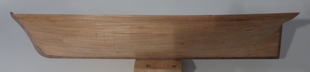
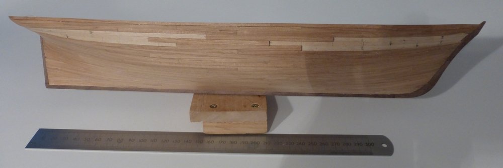
First thanks to everyone who has dropped in for a look, reacted to this or added a comment. Its all very encouraging. I have been making steady but slow progress since my last update. I have completed planking the first side up to level with the top of the false deck, which is at the same level as the top of the beams that would have supported the deck on the real ship. I have started drilling holes to represent treenails, which can just be seen in this picture. I have not finished, but I have tried various alternatives to simulate treenails in some of the holes: Cocktail sticks – After being cut off and sanded these were virtually invisible. Wood filler – Not quite the best colour but a possibility. Offcuts of the wood used for planking made into treenails – The end grain shows up quite nicely against the planks. Not too obvious but they are there. As I type this I realise I have come to a decision that this is the way I will go. I have calculated there are about 1000 to do each side, excluding the bulwarks. First time I have done this, see how I get on. I was trying to do these with a 0.4mm drill, but after getting through a few drills, either bending or breaking, I moved up to 0.5mm where I am still on my first drill. I am using a pin as a centre punch and drilling by hand. Just noticed the pin is in the last picture, just under the model on the left with a white head. I do think one of the reasons for things going better with the 0.5mm drill is just that it is a better quality drill to start with. I do find it is a problem getting good drills at a reasonable price in this size range. The really cheap ones are just junk and I do not like paying too much for something where I have no idea beforehand of the quality. This picture better shows some of the holes I have drilled. The rows are on what would be alternate frame positions. At this scale I think to do every frame position would look a bit crowded. Sorry about the shadow. Another view of the first side. A view of the other side with the first 3 planks of the wale in position. And a closer view. To get the holes in the right place I am using masking tape. Unfortunately I only thought of this after the first few rows, one of which turned out a bit wonky, which got me thinking about how I was doing this. I also wish I had thought of this before doing the planking as using masking tape would have made it much easier to draw the lines corresponding to the frame positions onto the first planking. Though I would still like a laser level. Glenn
-
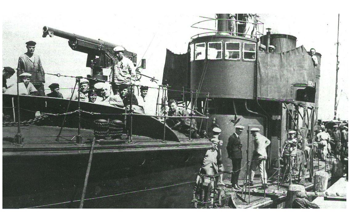
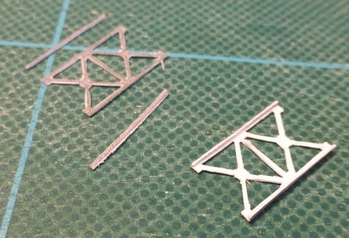
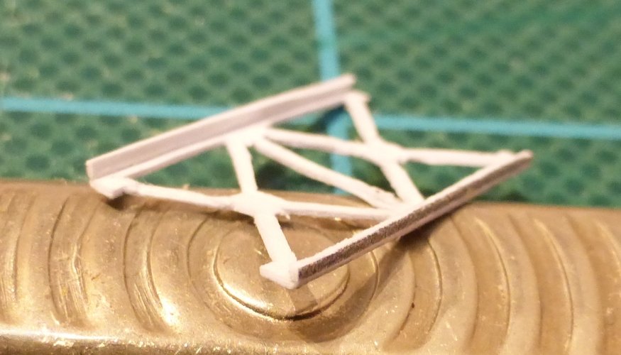
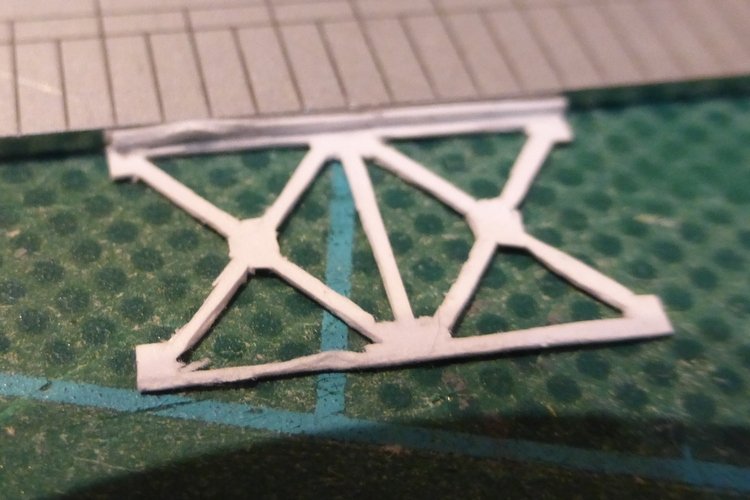
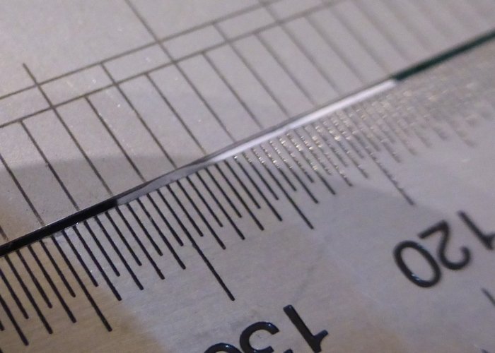
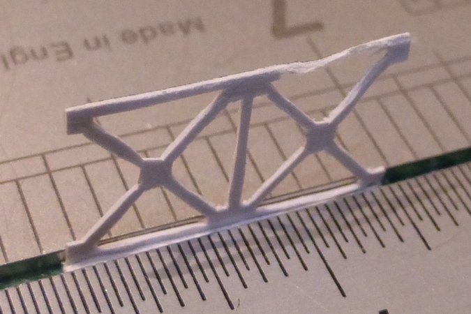
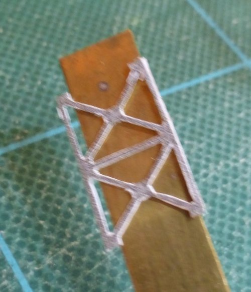
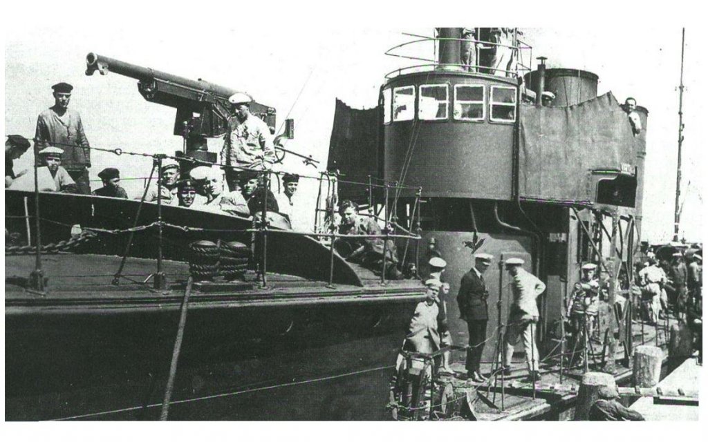
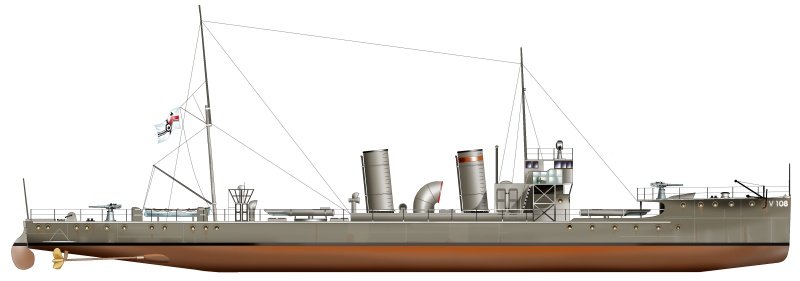
First thanks to everyone for looking in and to those who have clicked on the like button. I now move onto the bridge wing supports I made the first one of these and then thought I should document the process while making the second. I think because of this the second did not turn out as well as the first, I was too concerned with taking pictures. It looks damaged in a couple of places but this does not show without the enlargement. As mentioned a few posts ago these parts are marked as if the edges should be scored and folded to make them into angle girders. Given the dimensions this is something that looks to me to be impossible. Though I was thinking it might be possible to leave more card on, then fold them and then cut the excess off. So instead of making the two end bits into angle girders by scoring and folding, I will cut the side pieces off and then glue them back on at 90 degrees. This shows the first one done and the second prepared by cutting off the ends. Another view showing of the first one, showing the end pieces glued in place at right angles. Unfortunately the image is suffering from barrel distortion. After cutting off I apply glue and position the end piece. Then squeeze between two rulers to make sure it makes a good contact. After this I put the ruler on top of the end piece and pressed down to make sure it was flush with the end of the main piece. Then just to make sure I turned it round and repeated the process. Giving a good push with the second ruler to ensure the end piece is flush. Since I took these pictures I have got out my set of miniature, 1.5mm chisels and used them to clean up some of those bits hanging off, that I did not notice until viewing the pictures. I then repeated this with the other edge. For the final stage the ruler was too wide, so I used a piece of brass strip instead. Sorry this picture is a bit fuzzy. I still need to paint all the edges and the rear where the white card shows. I will also glue in short lengths of brass rod at the bottom protruding over the ends to make location pins as suggested by Chris. Also here isa picture and an image I dug up that I thought might be of interest. Glenn
- 10 replies
-
- 4
-
-
- v108
- digital navy
- (and 1 more)
-
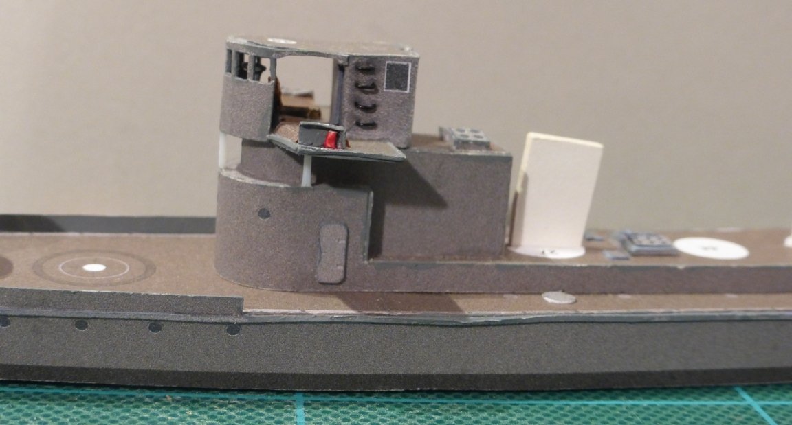
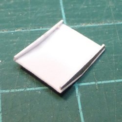
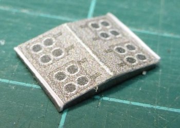
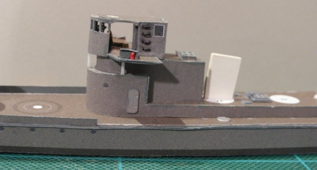
Chris, I know what you are saying is true, but they still make me feel I should be able to do a better job. Catching up on progress. There has been some delay as my illuminated magnifier failed and I had to purchase a new one. The old one was the type with a circular fluorescent tube around the lens. The new one has LED’s around the lens and can be powered from a USB output, like a phone external power pack. With the fact that it has a clip that opens to just over 2 inches makes it much more versatile than the old one. I made the skylights. Instead of scoring and bending the sides I cut them off and then glued them in place. First I scored the centre line then glued the top to the ends. I ensured these were flush by positioning the end piece, then standing it on its end and gently pushing the end piece down with tweezers. Then added the side pieces. Next will add the cut out pieces on top to give it some depth. Will touch these up with paint once they are dry. I added some steps to the side of the radio room. They are about 2mm wide and about 1mm proud of the surface. Learnt a few things here. Should have drilled the holes before assembly. Had to push quite hard to drill the holes which buckled the side a bit. Tried a sharp needle, but that did not work. Should have backed where the holes were drilled with 1mm card to help retain the steps as I pushed them in. Hopefully the ones on the funnels will go more smoothly. Since I took the picture above I have touched up the edges with paint. A couple of shots showing overall progress of the superstructure. I have fitted the bridge and made the supporting struts from 0.5mm plastic rod. Obviously these still need to be painted. Next to do are the supports for the wings of the bridge. Finally get round to those angle girders. Then the two funnels and part 44. There is just one problem with part 44, I have lost all the pieces bar one. Will have a good search and then if I cannot find them I will have to print some more. Annoying, though they are not the first parts I have lost, they are the first parts where I do not have alternatives printed on suitable material. Glenn
- 10 replies
-
- 6
-
-
- v108
- digital navy
- (and 1 more)
-
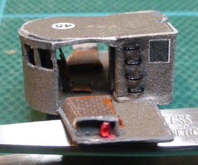
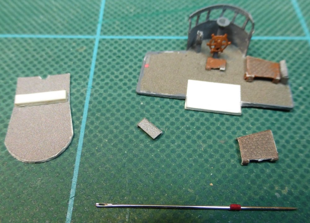
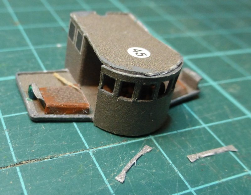
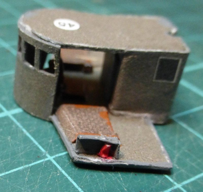
Chris, thanks for the encouragement. When I get there I certainly intend giving angle girders a go. It’s been sometime since I last got around to updating my logs. I have been making steady progress, 2 steps forward, 1 step backwards. I have been steadily working on the bridge assembly. It takes a long time to cut out all the small parts For the port and starboard lights I cut them out slightly longer, about double the length and then rolled them round the thinnest needle I could find. I was not too happy with the way cutting out the windows turned out and after I glued the piece in place I accidently squashed the top slightly and had to try and straighten it out. I also glued a bit of scrap across the underside of the roof to help when fitting the radio room. So about a week ago I had got to the point where this was all assembled. As I had some spare time I put it aside to do some work on the Scottish maid. When I came back it looked like I had sat on it. Do not know what had happened, no one else to blame. The front piece with the windows cut out, that I had squashed before was now in a very sorry state and the radio room had come away from the floor. At this point I decided that the front piece needed replacing, but I could just stick the rest back together. As I still had this piece on the thicker (0.33mm) card I originally printed I cut that out and used that. It cut out much better than the thinner card and the extra stiffness was a real bonus with the very thin frames. It looks a bit rough on top in the following pictures, may try using some filler. I still have the two side pieces to glue in place and then work out what I am going to do about the railings. I have downloaded the suggested template, but I might make my own template for this bit using the printed ones as a guide. There is a bit of scrap wood visible in this picture that I did not notice until I had downloaded them. I can see in this last picture that I have also squashed the red tube I made for the port light, must be more careful in future. Also my scoring and folding of small pieces in thick card is not very good, they spring back too much. Next bits I intend making are the skylights, instead of scoring and bending the side pieces I will cut the parts off and glue them together. I think I am getting a bit untidy in what I am doing here, as shown in the pictures. The trouble being that I cannot see any of this until I view the pictures. Using the illuminated magnifier I normally use during building I cannot see these issues. Especially the brown paint which is otherwise indistinguishable but stands out in the pictures. Once or twice I have felt like I want to start again, but I then think I am better seeing it through and then attempting something else of a similar nature. Glenn
- 10 replies
-
- 4
-
-
- v108
- digital navy
- (and 1 more)