
Chuck
-
Posts
8,985 -
Joined
-
Last visited


.jpg.d84ec4dad1d7791e855dca06210ab6f3.thumb.jpg.f45209242e851d4409eca1a09293165b.jpg)
About Chuck

Recent Profile Visitors
38,477 profile views


-
 Saburo reacted to a post in a topic:
Naval Cutter Alert by AnobiumPuncatum - Scale 1/36 - POF
Saburo reacted to a post in a topic:
Naval Cutter Alert by AnobiumPuncatum - Scale 1/36 - POF
-
mugje reacted to a post in a topic:
Sloop Speedwell by Chuck - Ketch Rigged Sloop, 1752 - POF
-
Chuck reacted to a post in a topic:
Sloop Speedwell by Chuck - Ketch Rigged Sloop, 1752 - POF
-
Chuck reacted to a post in a topic:
HM Cutter Cheerful 1806 by niwotwill - Syren Ship Model Company - scale 1:48
-
MEDDO reacted to a post in a topic:
Sloop Speedwell by Chuck - Ketch Rigged Sloop, 1752 - POF
-
Dowmer reacted to a post in a topic:
Sloop Speedwell by Chuck - Ketch Rigged Sloop, 1752 - POF
-
 Thukydides reacted to a post in a topic:
Sloop Speedwell by Chuck - Ketch Rigged Sloop, 1752 - POF
Thukydides reacted to a post in a topic:
Sloop Speedwell by Chuck - Ketch Rigged Sloop, 1752 - POF
-
Chuck reacted to a post in a topic:
Sloop Speedwell by Chuck - Ketch Rigged Sloop, 1752 - POF
-
 giampieroricci reacted to a post in a topic:
HMS PEGASUS by giampieroricci - Scale 1:36 - Swan-Class Sloop from plans by David Antscherl & Greg Herbert
giampieroricci reacted to a post in a topic:
HMS PEGASUS by giampieroricci - Scale 1:36 - Swan-Class Sloop from plans by David Antscherl & Greg Herbert
-
Chuck reacted to a post in a topic:
Armed Virginia Sloop by CiscoH - Model Shipways - 1:48
-
fake johnbull reacted to a post in a topic:
Sloop Speedwell by Chuck - Ketch Rigged Sloop, 1752 - POF
-
westwood reacted to a post in a topic:
Sloop Speedwell by Chuck - Ketch Rigged Sloop, 1752 - POF
-
JpR62 reacted to a post in a topic:
Sloop Speedwell by Chuck - Ketch Rigged Sloop, 1752 - POF
-
Chuck reacted to a post in a topic:
HiSModel - Historic Ship Models
-
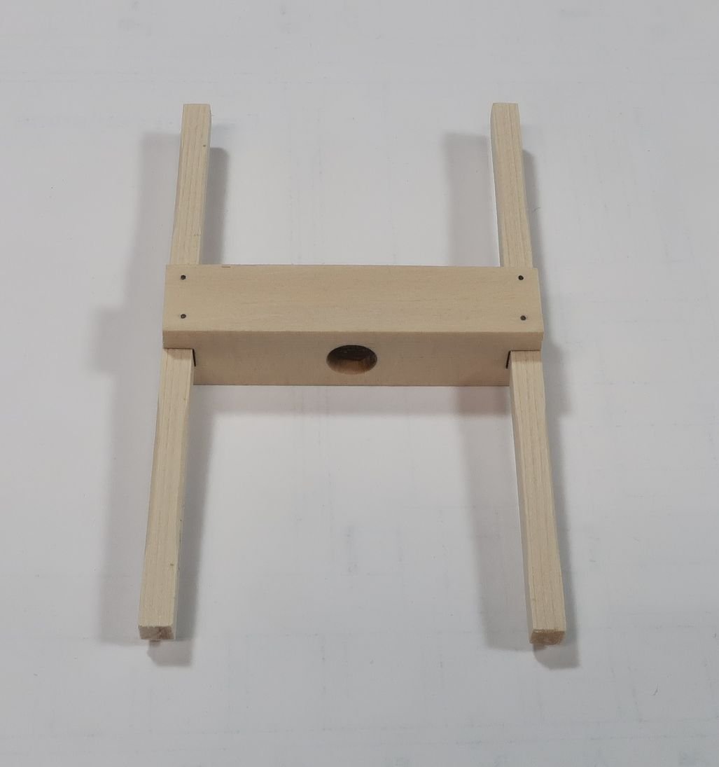
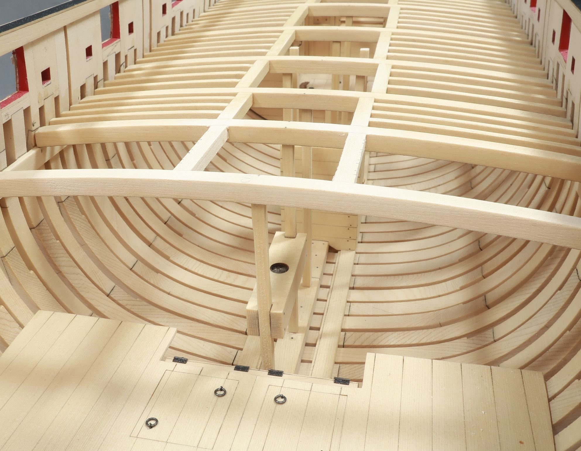
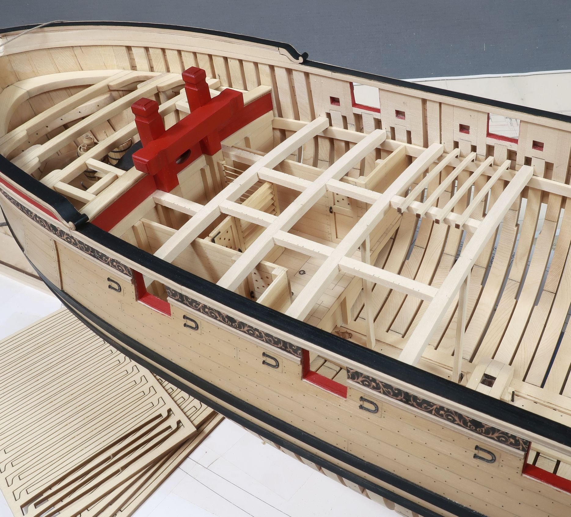
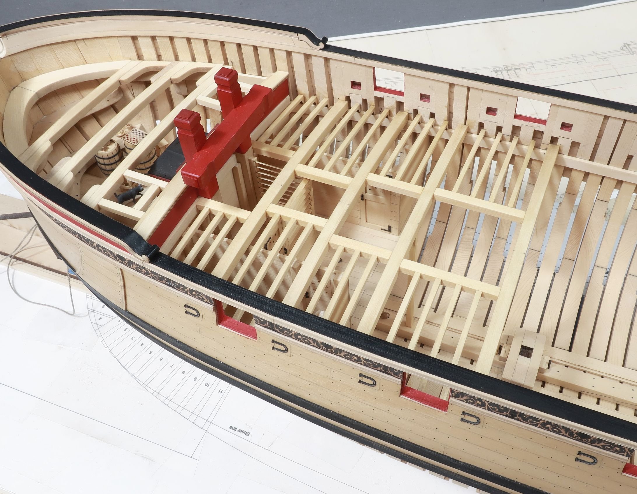
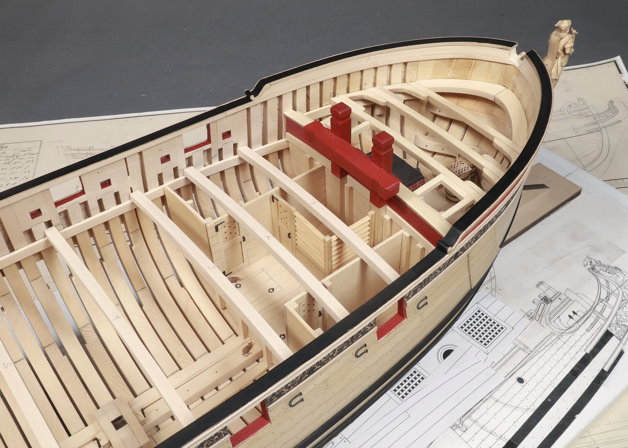
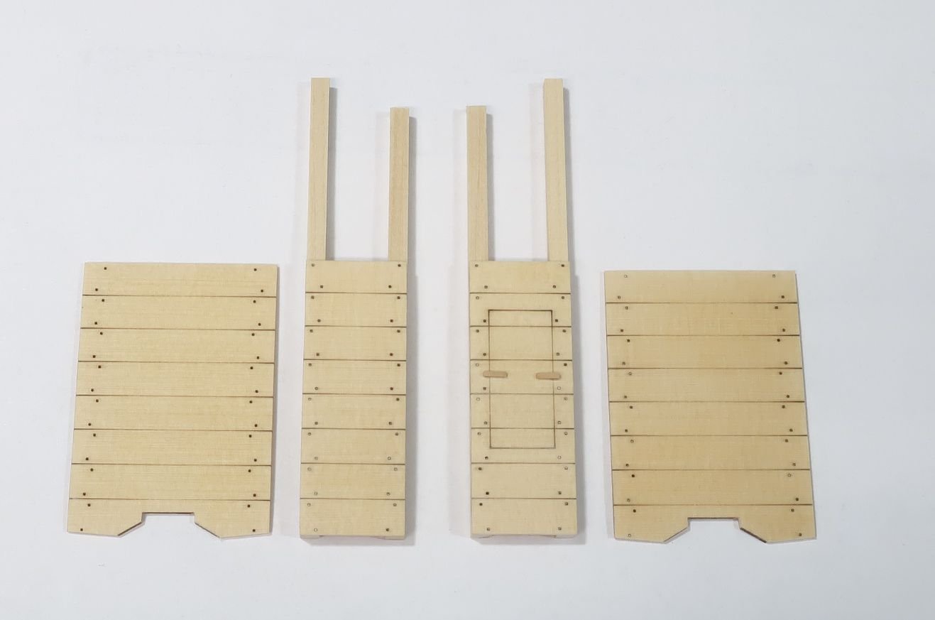
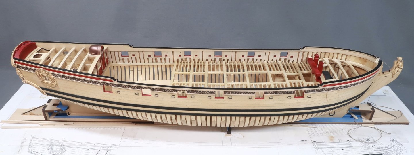
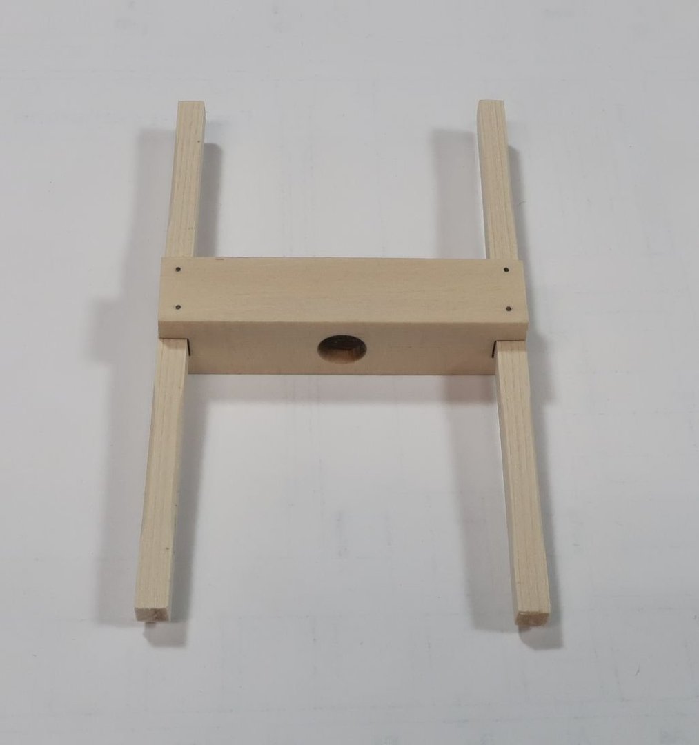
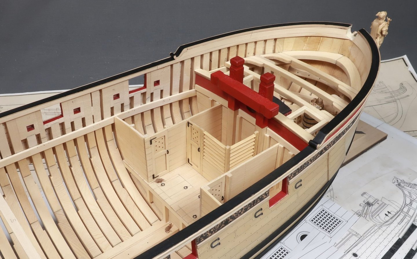
 Thank you for saying... I am trying to set aside time regularly to make a little progress. Continuing with the center line fittings below deck, the WELL was next up. This is a relatively simple structure. The four sides are laser cut and etched. You need to do just a few things before you glue up the four sides. First...make sure the fore and aft sides sit nicely on the keel. Once you adjust them as needed, you can cut the four upright columns to length. How do you determine the length of these. The two aft columns are shorter. These are simply cut to fit under the next deck beam. No big deal. The two columns on the fore side of the well are different and taller. These two columns are cut so the tops are flush with the TOP of the gun deck beams or carlings. You will have an opportunity to sand these shorter so dont over sand them initially. Assembling the well is straight forward after you glue the columns to the port starboard sides of the well ahead of time as shown above. You can also use some scrap tiny strips of wood to make the toggle handles for the access door. Then just glue them on. They are clearly shown on the plans. With the four sides glued up and square...test it on your model. After any minor tweaks you can glue it position permanently. Then the next few gun deck beams, carlings and ledges were taken care of. Eventually you will get to the beams where the capstan step needs to be built along the center line. So you will need to stop and assemble the capstan step. I glued those appropriate deck beams in position so I had a reference point to test fit the step periodically. The step is also laser cut for you and has a recessed circle in the center. This will accept the heel of the capstan drum...eventually. The step is bolted to two columns that are set on top of keel. These two columns are 1/8" x 1/8" strips just like the other support columns under the beams. Hopefully you havent forgotten to add any up until now. They are all shown on the plans. You must cut the two columns to fit under their respective gun deck beams. Now you have to determine where along those beams the capstan step will be placed. You can use the plans of course but it is doubtful it will match your model perfectly. Mine didnt. So just understand that the capstan step is slightly higher the lower aft platform and it is level. Because you know this you can mark the columns for the height of the capstan step with the columns "snug" fit temporarily in position. When I was comfortable that I had the proper height worked out, I was ready to glue it in position. But first I had to add the simulated bolts on the capstan step. I used 25 lb black fishing line to simulate these. And yes the photo shows the step upside down so you can see the hole for the drum. But rest assured it will be glued in position right-side up!! The capstan step in position...and the carlings added afterwards. And some other views...of the gun deck up to this point with the ledges completed. Almost to the other side of the gun deck. But next up are all of the cabins on the aft lower platform. Onward and upward as they say!!
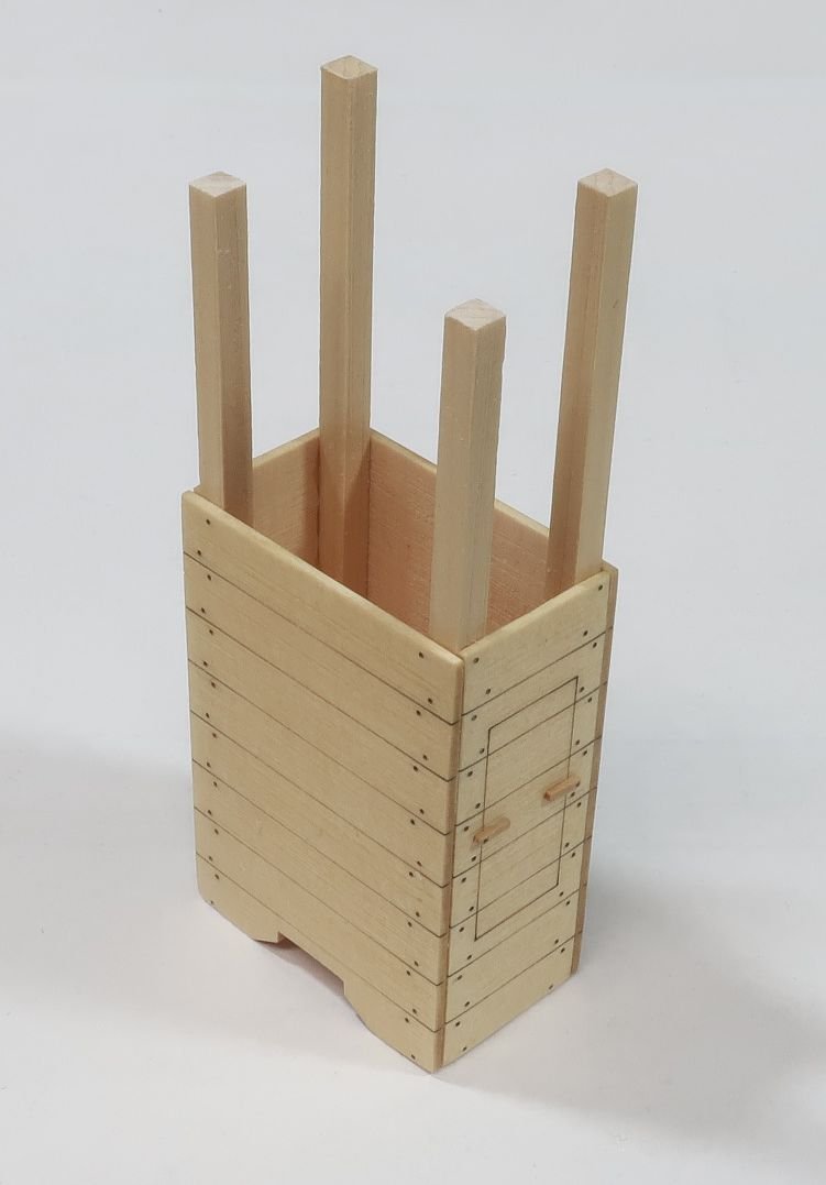


- 779 replies
-
- 36
-
-
-
- speedwell
- syren speedwell
- (and 1 more)
-
Really nice work on the model. You have a nice clean model there. Well done.
-
Chuck reacted to a post in a topic:
Mayflower 1620 by rlwhitt - Model Shipways - 1:76
-
Chuck reacted to a post in a topic:
HMS Winchelsea 1764 by glbarlow - 1:48
-
Chuck reacted to a post in a topic:
HM Cutter Cheerful 1806 by Erik W - 1:48 scale
-
Chuck reacted to a post in a topic:
Sloop Speedwell 1752 by Rustyj - Syren Ship Model Company - 1:32 Scale - POF Sloop
-
Really nice work Rusty.
-
Looking nice and clean
-
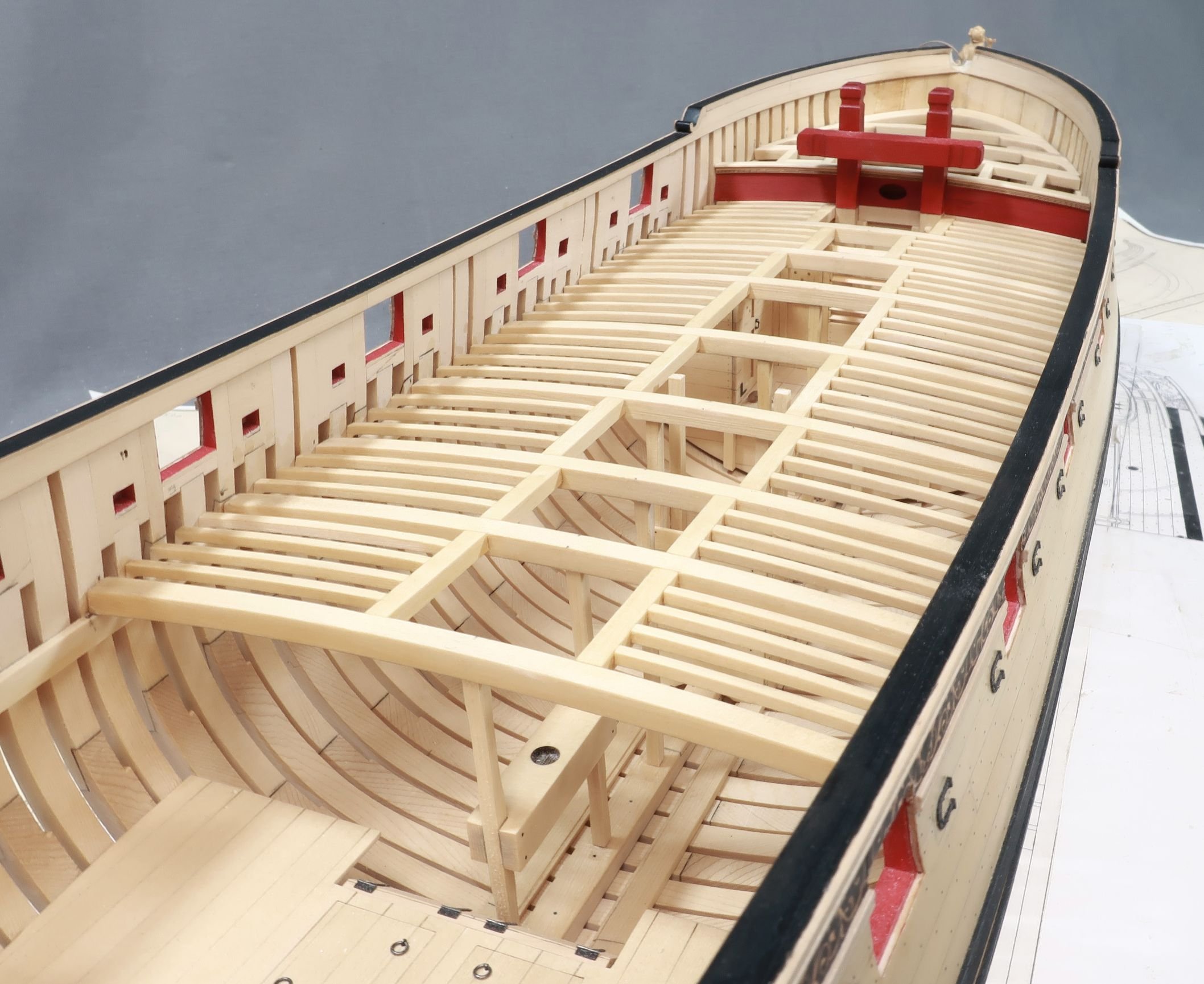
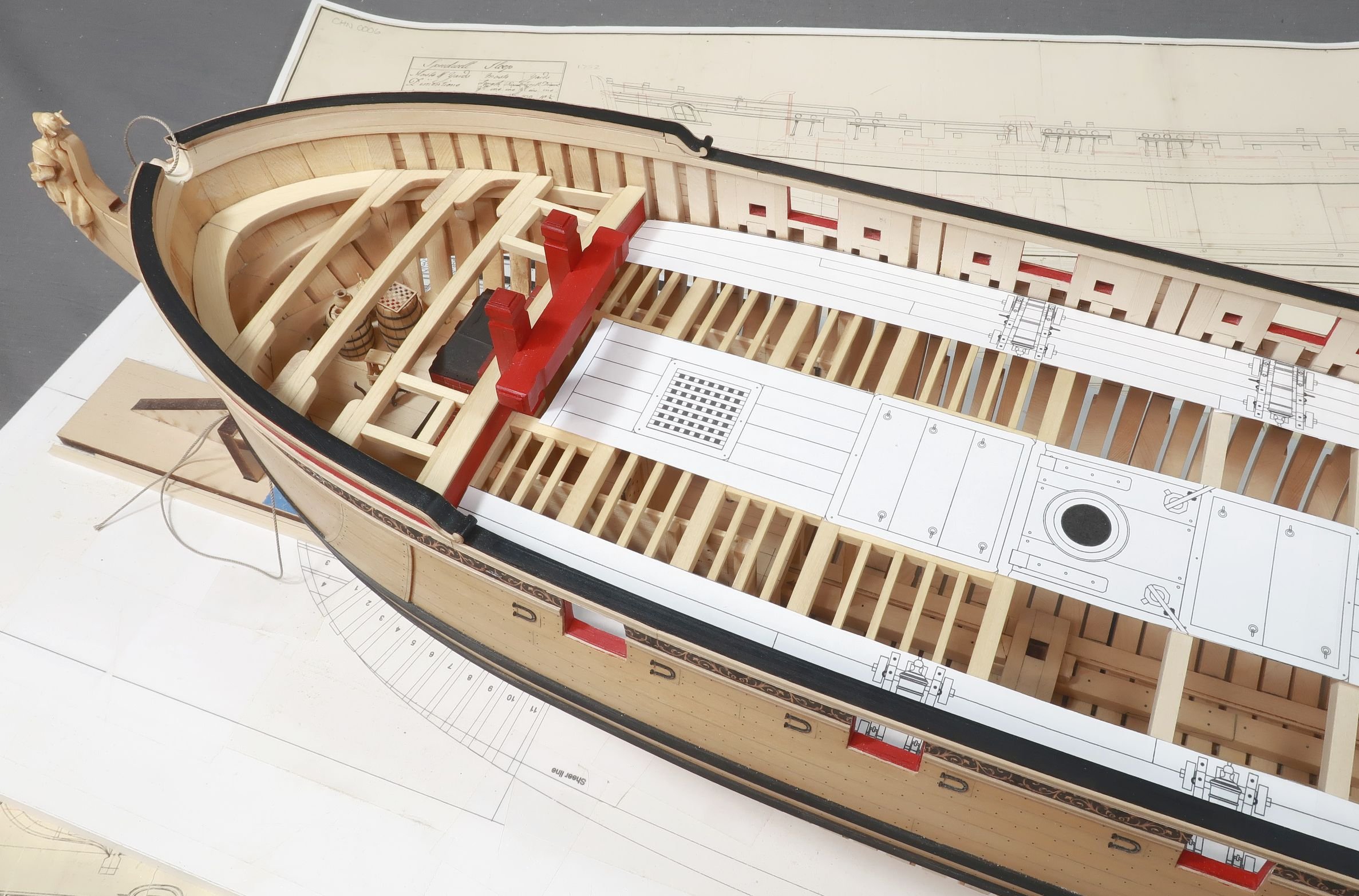
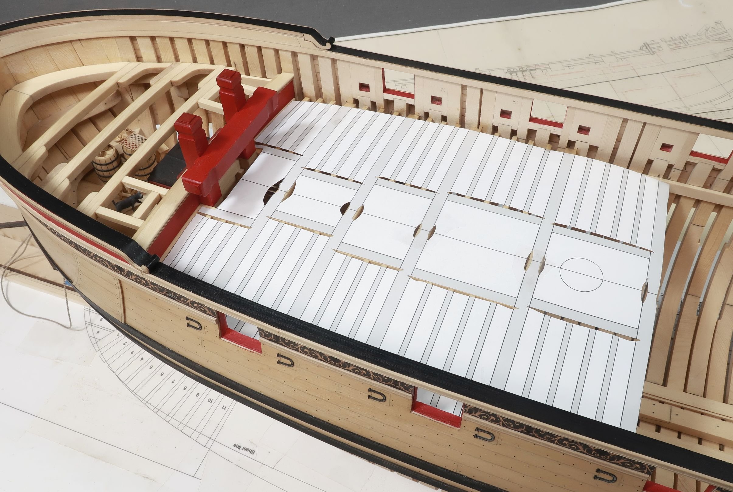
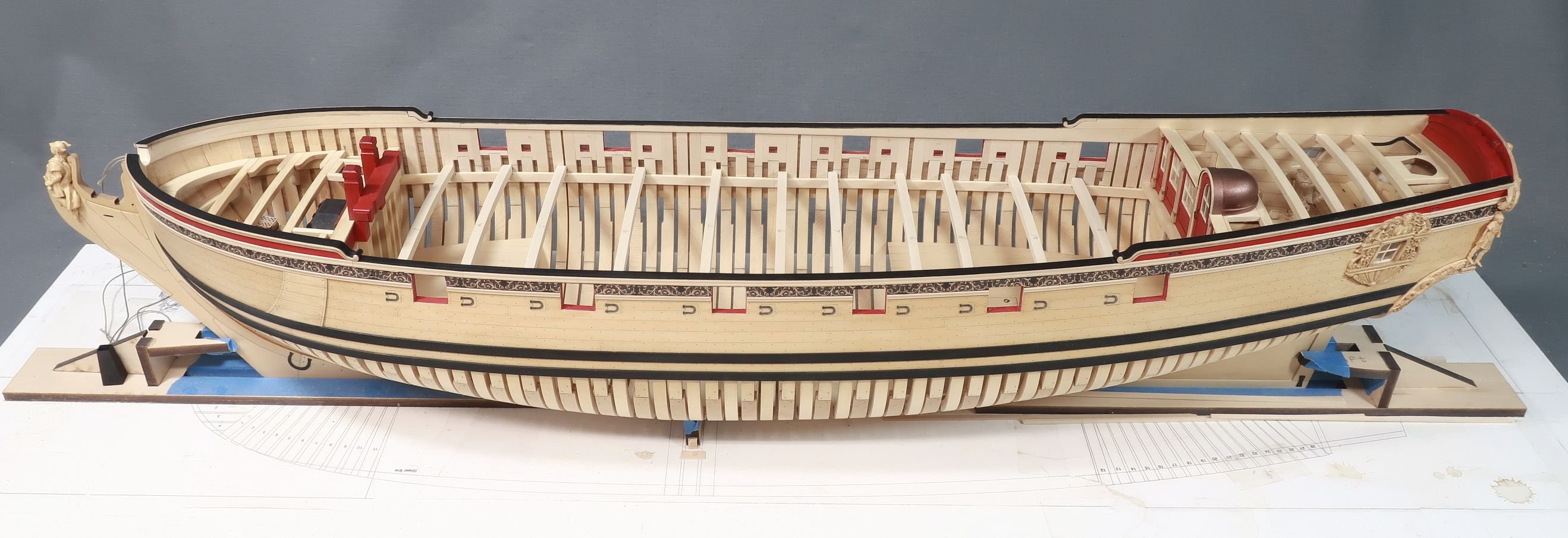
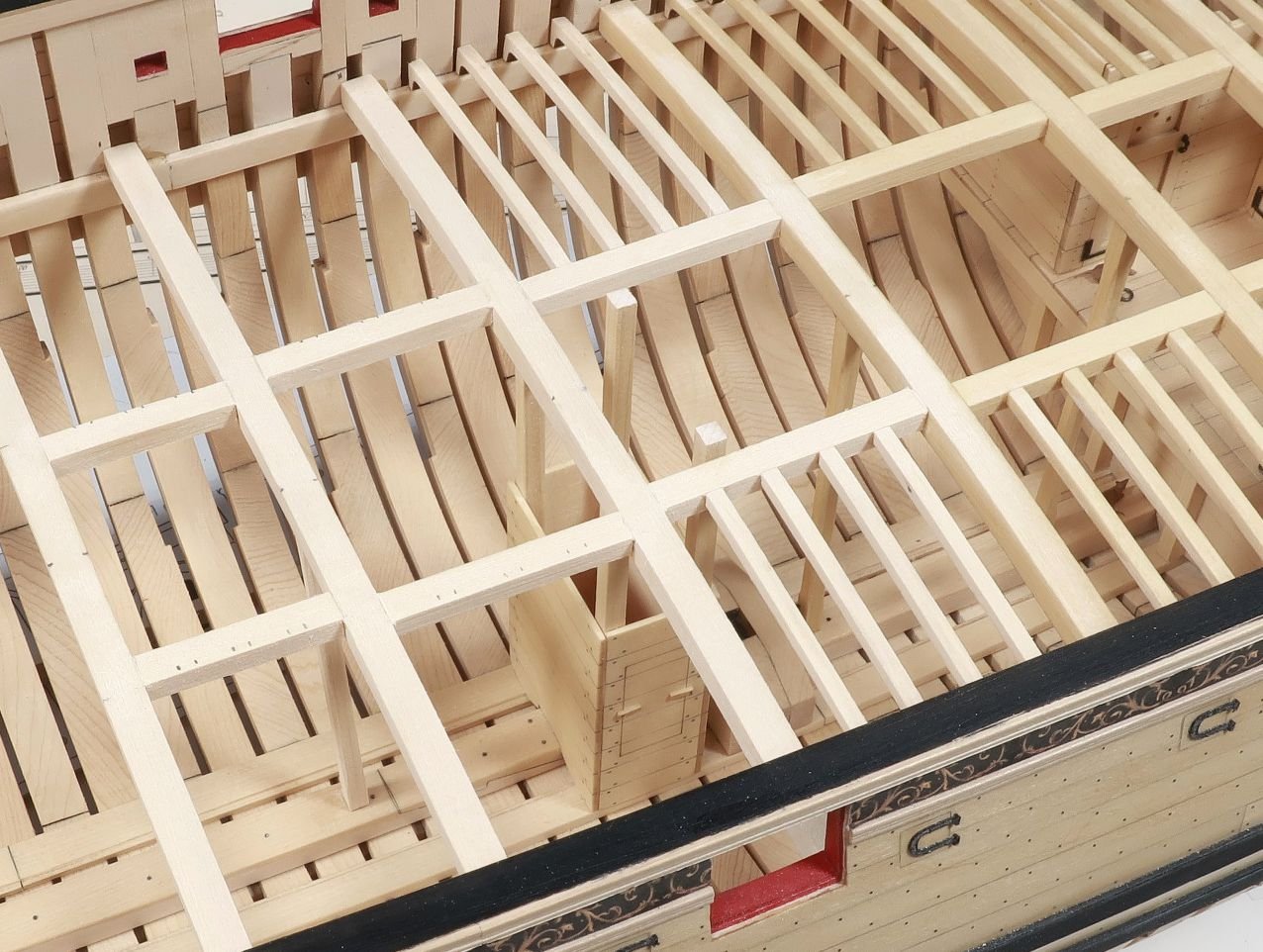
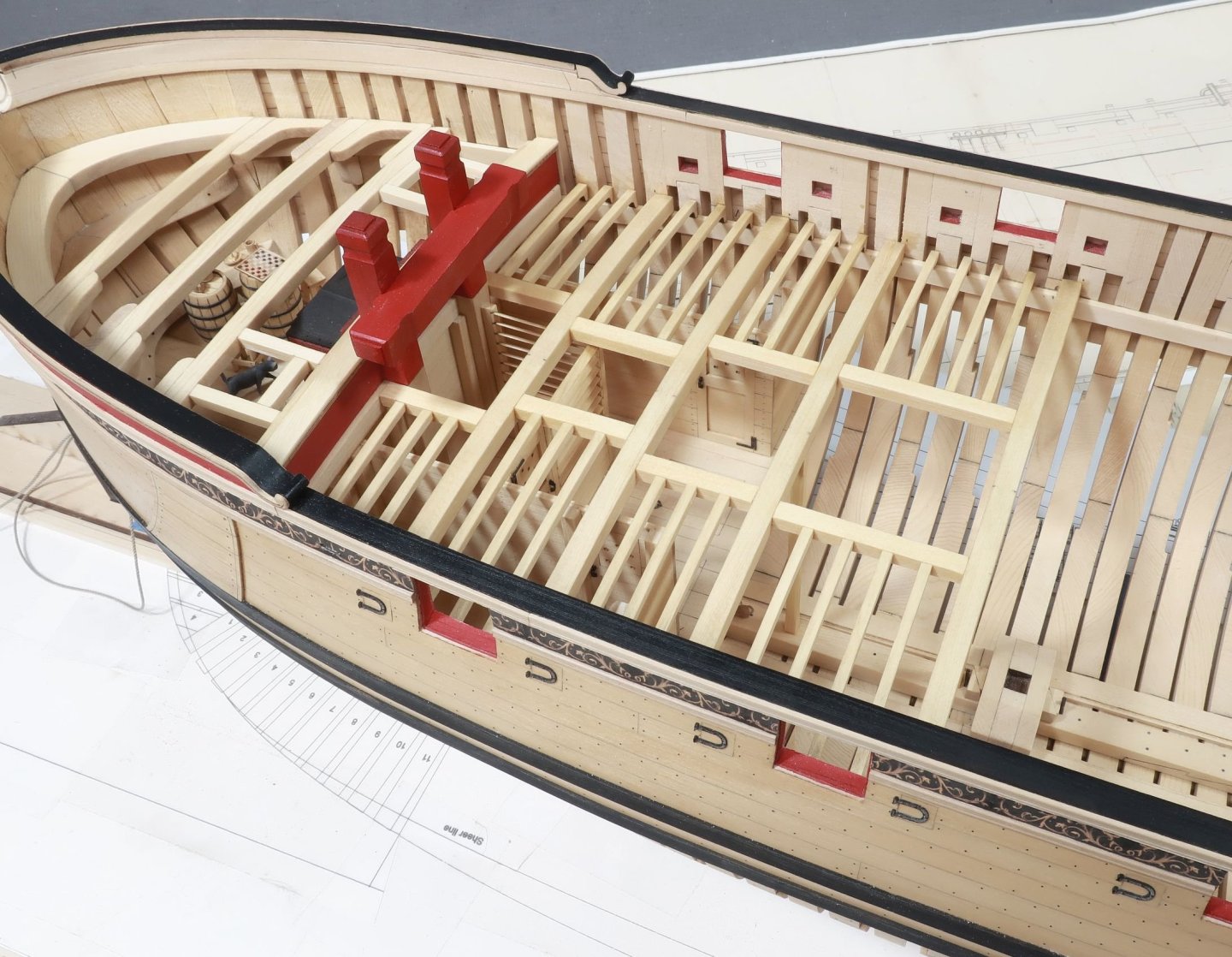
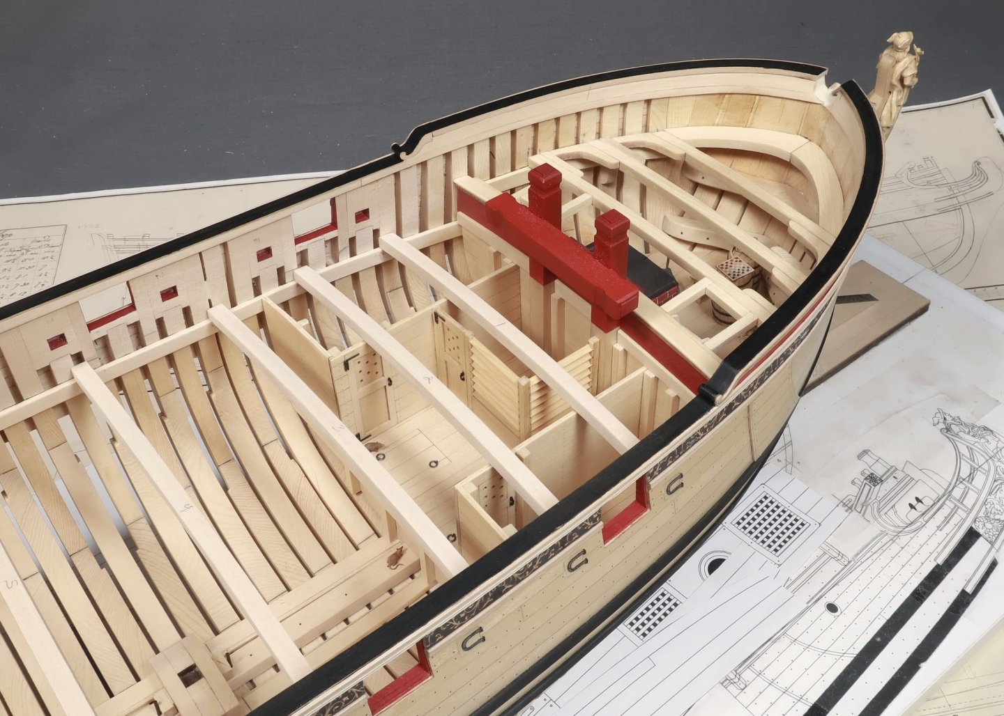
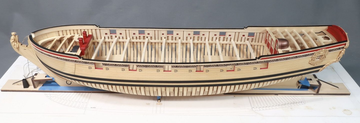
Just a quick update. It might not look like a lot of work was done since my last post but you would be surprised how involved the deck beams can be. With the cabins on the fore lower platform completed, you can start adding deck beams above them. No reason to wait until everything is built below deck to do so. In fact, waiting to do it all at one time wont be very enjoyable. Doing it this way breaks up the task a bit. This kit will be very simplified compared to the books. Because we will be planking the gun deck in the "classic" contemporary model style, there is absolutely no need to make and add the hanging and lodging knees. In fact, this would up the difficulty factor by about ten. So we will just be adding the deck beams with all of the carlings and ledges. You can however follow the Seawatch books and scratch build the knees should you really want the total experience. The photo below has a lot going on that was completed. First, The first four deck beams were glued into position... Then the carlings were added between them as shown on the plans. The carling are cut to length using 3/16 x 5/32 strips. Lastly you may notice that the after most beams have a column under them at the center. These are just 1/8" x 1/8" strips cut to length. The corners are chamfered as shown on the plans. With the first four beams added you can now add the ledges. These are the thinner "partial beams" that extend from the carlings to the deck clamp. They are laser cut for you with a special "leg" on the outboard ends. This raises each ledge to the perfect height so it will be flush with the top of the gun deck beams. So when you are cleaning the char off these...DONT sand the bottom or even the end with this "leg" on it. Otherwise you wont have level ledges with your beams. Hope that makes sense. Now in that same photo above you can see the first few ledges (cleaned of laser char...no need to clean the bottom at all actually) resting in position. All you have to do is cut the end that sits against the carling and glue it on position. NOTE: Now yes indeed...all of the carlings should be notched in the deck beams. All of the ledges should be notched into the carlings. But you know what...I am not going to do that. And you dont have to either. It simplifies things so much this way and those many mortices and notches are not so easy to make. They will also mostly be completely covered up. So you can decide. Now this may all seem simple enough. But finding the exact locations for these beams, carlings and ledges is super important. Time and care must be taken to get their location correct....otherwise you will end up with hatches in the wrong position and mast holes too!! It could get ugly. So use the plans. If you have a second set printed. Go ahead and cut them up. You can see strategically placed cut outs on the template that allowed me to mark the locations of the carlings on the beams....and the ledges on the carlings. This template also helped me position the deck beams properly which is the very first thing you need to do. Finding you center line on those deck beams after they installed is also a huge help. Gluing the parts in is easy enough...but the marking, measuring and planning takes time and patience. Then its just a matter of cutting all of those ledges to length and gluing them in position. There are a lot of them. I believe 86 in total. Note that these would also be down the center between the carlings and hatches also. But once again they will be entirely covered up and its just a repetitive exercise that nobody will ever see. To show you how the knees and other details like the ledges wont be seen...here is a look at this area with the deck planking cut and placed on the model as a test. This shows what will be very close to the final appearance using the "classic contemporary model appearance". But everyone can always deviate from that should they want to.


- 779 replies
-
- 43
-
-
-
- speedwell
- syren speedwell
- (and 1 more)
-
You are good to go...that one element (keel assembly) on the plans printed at the incorrect scale. The laser parts are all correct so just keep going. The plans have been corrected. The guy at my printer must have grabbed the edge of that object in error and shrunk it horizontally (in Corel Draw). At least that is what he said happened. If you lay those pieces on the framing plan instead you will see they fit just fine. Chuck
-
Thank you…i will continue making more. I have no plans to limit production. In fact I just listed two more sets of the first two chapters. More will follow as time and wood supply permits.
- 779 replies
-
- 8
-
-
- speedwell
- syren speedwell
- (and 1 more)
-
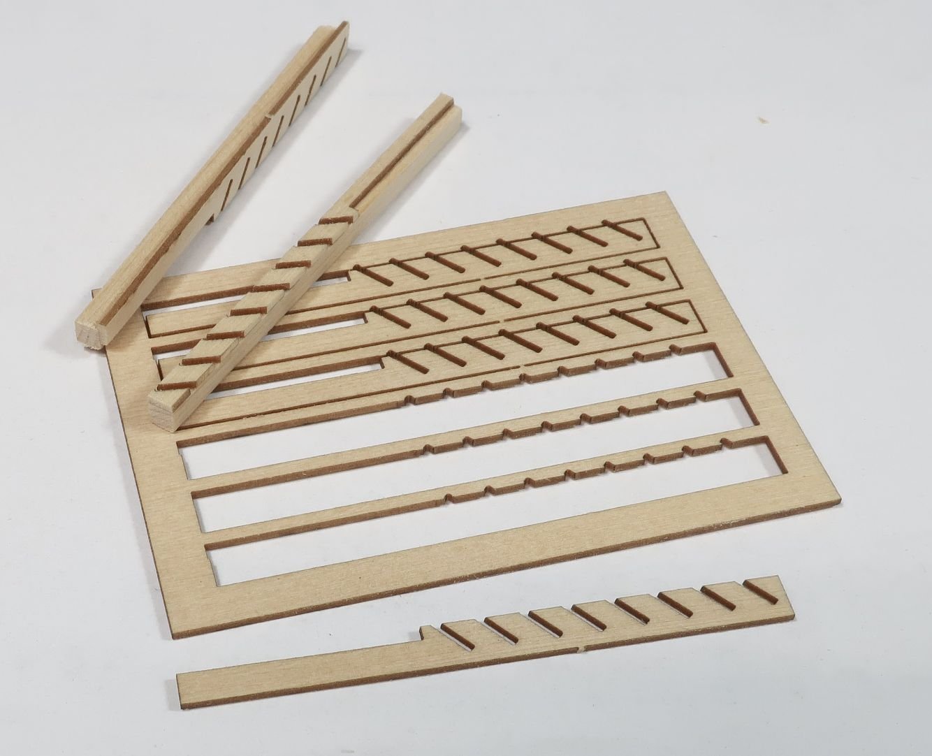
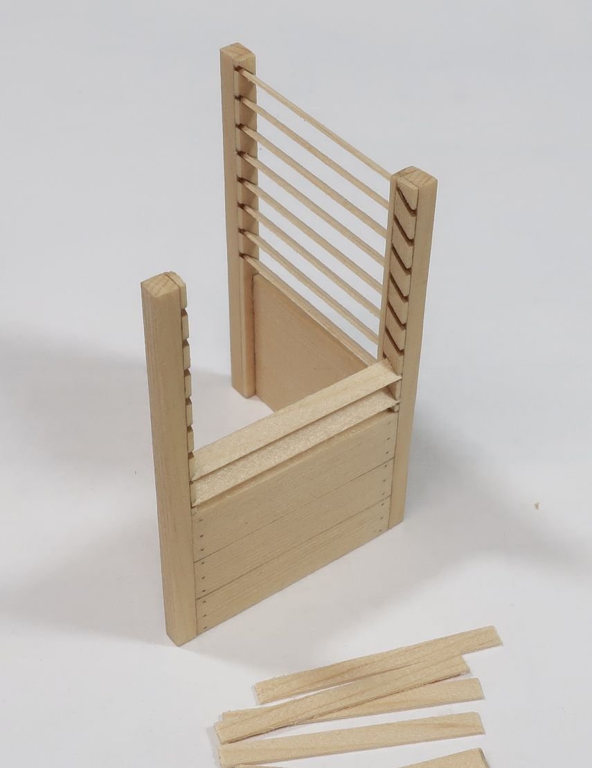
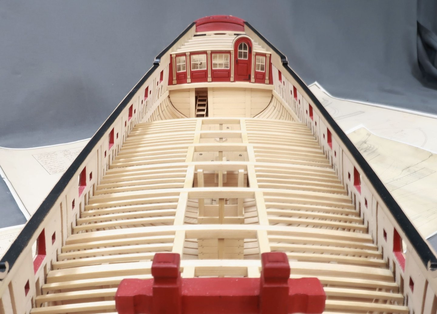
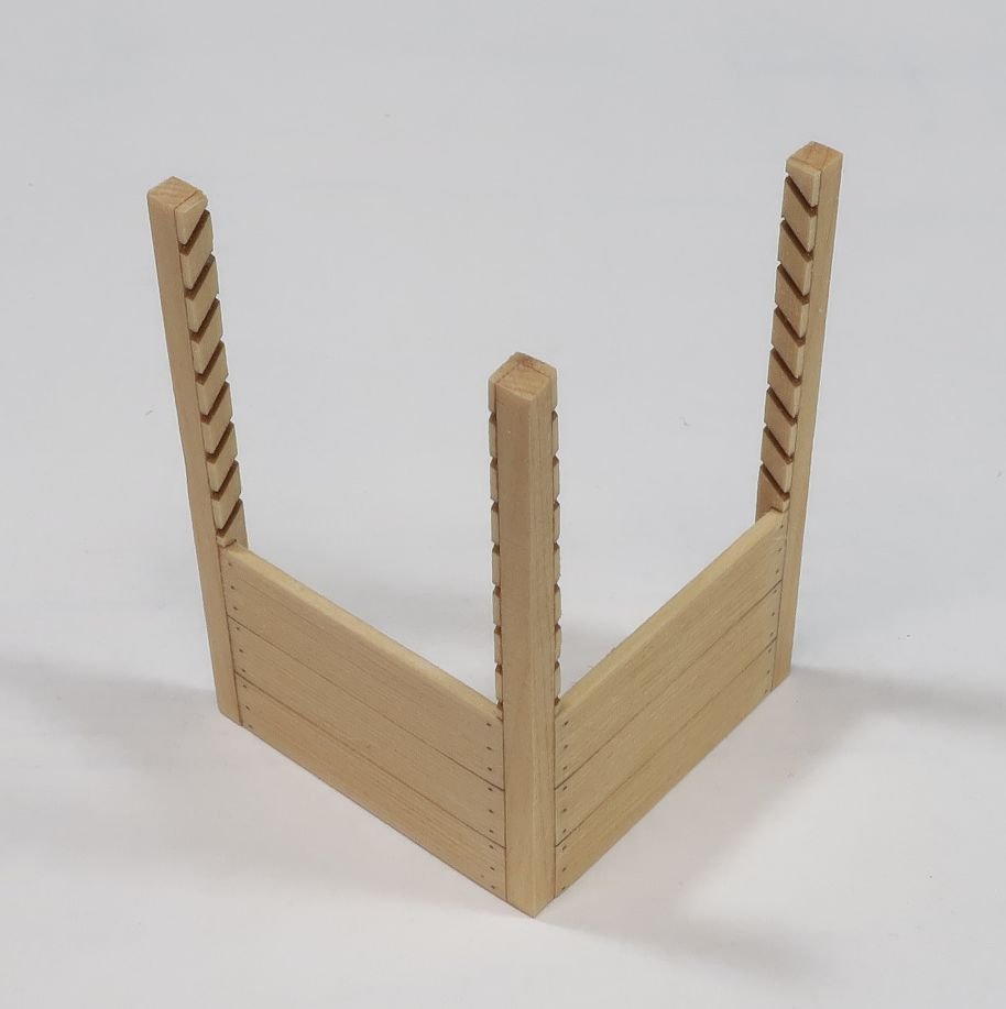
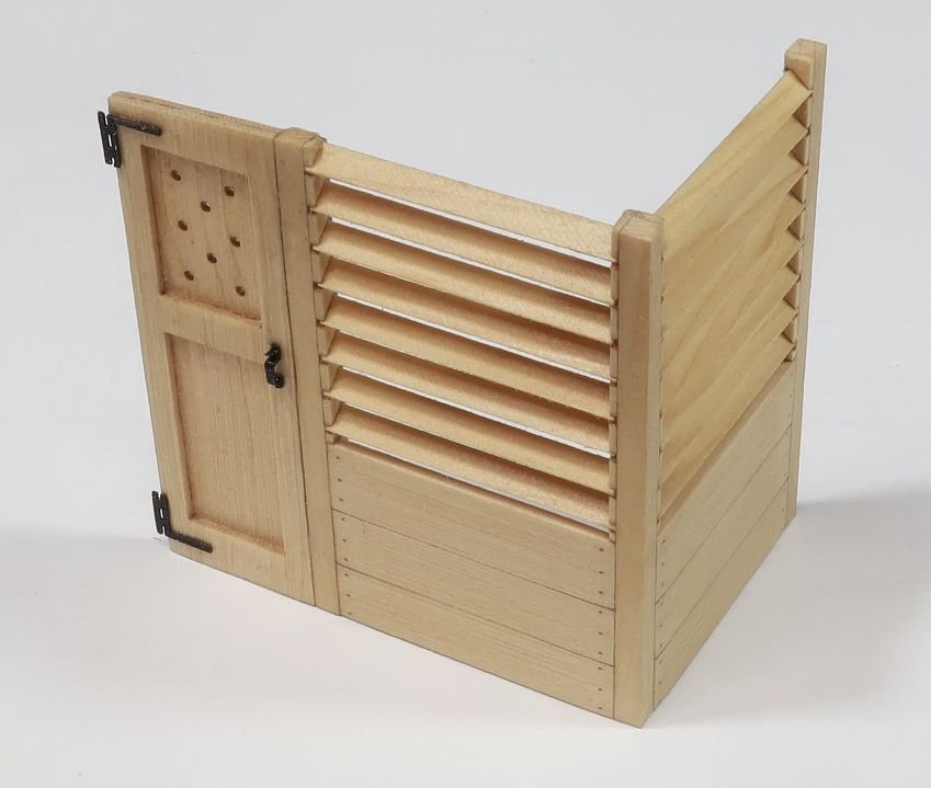
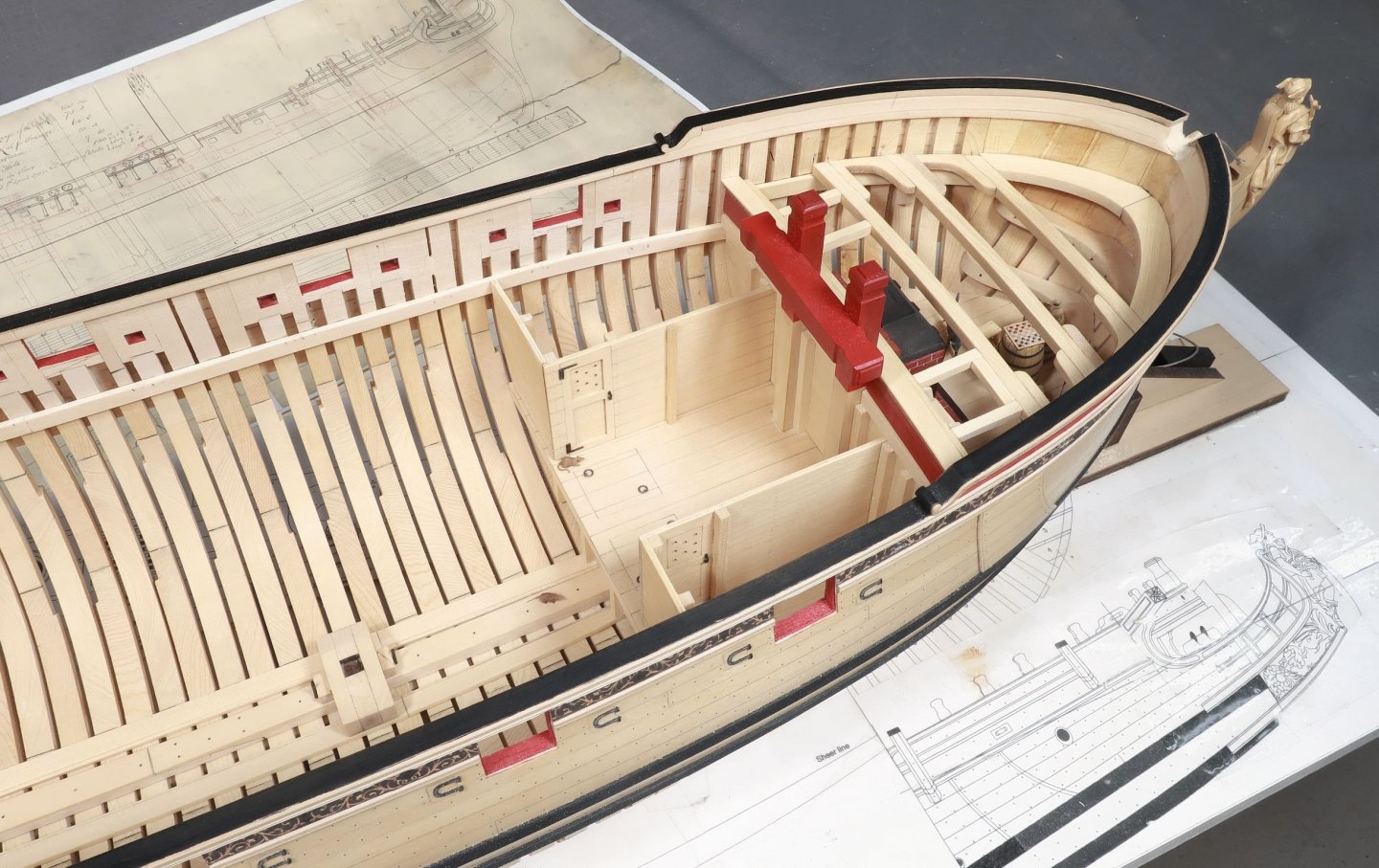
Thank you guys... I took a crack at the sailroom. First I had to make the posts for the partitions. There are thin laser cut strips that need to be glued to the sides of some 3/32" x 3/32" strips. It might be hard to see but the laser cut strips are wider than needed. You have to line up the open side with the edge of the 3/32" strip. Let the other side hang over. The upright on the left shows this. Once the glue dries, you can sand that overhang down flush with the 3/32" strip. This will leave rows of slanted slots for the louvers. They should be open on both sides after sanding off the overhang. There is also a long slot down the front edge that is created. This is for the planked bottom of each partition. It is all shown on the plans. The corner post gets two of these laser cut strips with the notches. Just be careful when you glue them on so they are facing the right direction and the louvers will be able to slip into the slots easily. Next I added the laser cut planked bottoms. This essentially makes a nice two-sided partition. The planking will fit into those long notches on the posts. It is probably easier to see them in the photo below. Keep a nice 90 degree corner with both sides. Then its time to fit all of the louvers...for ventilation. They are 3/32" x 1/64" strips. Just cut them to length and start adding them. Eight on each panel. To finish off the sailroom..I made the door. This is in two layers like all of the other bulkheads. I made the door up and added the hinges and door handles. Then I glued it to the louvered section of the sailroom. Like this. Now I could easily position the entire sailroom...hopefully. It should line up and fit onto the 3/32" post already on the boatswains cabin. And yes...we can finally glue the riding bitts into position permanently. This pretty much finishes the cabins at the bow. I was originally going to add a sail rack in the sailroom. But after a lot of thought I realized it would never be seen. The sailroom is pretty much covered up entirely by the deck planking and the deck beams. In this photo I have fitted the deck beams as a test. There will be several more between these larger deck beams too. There are thin 3/32" deck beams...sometimes 3 or 4 between each of these larger deck beams. They will obscure so much of the lower deck items. But hopefully you will get a glimpse of some of this stuff as it is quite a bit of work to build it all. The contemporary model with its many deck beams..


- 779 replies
-
- 41
-
-
-

-
- speedwell
- syren speedwell
- (and 1 more)
-
And nobody will ever see that detail once the deck beams and deck planking are completed. Too funny Greg. It actually takes a lot longer to design and draft these partitions than it does to build them. Once they are actually laser cut, it takes no time at all to clean them up and install them. If only I could find someone else to do that front end work for me. The sail room partitions wont be fun to design I can tell you that.
- 779 replies
-
- 10
-
-
- speedwell
- syren speedwell
- (and 1 more)
-
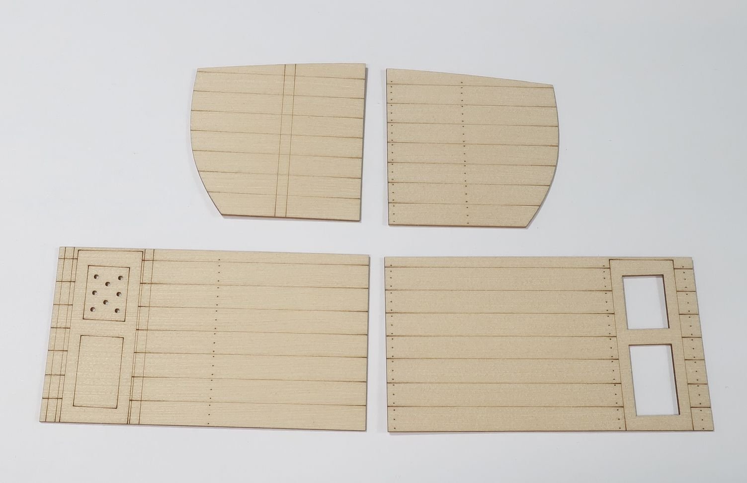
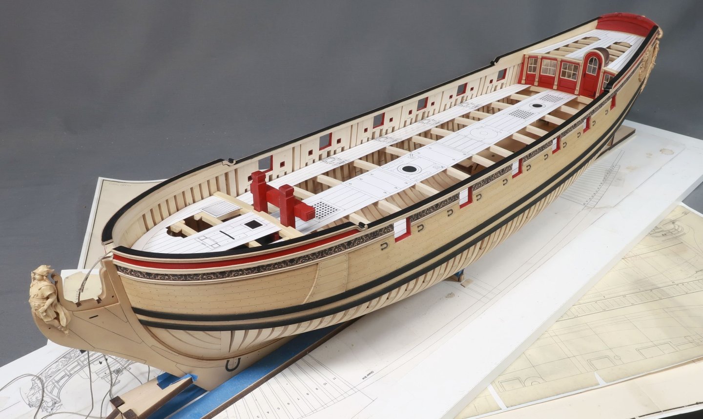
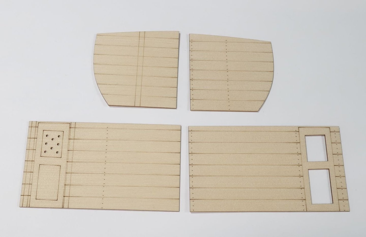
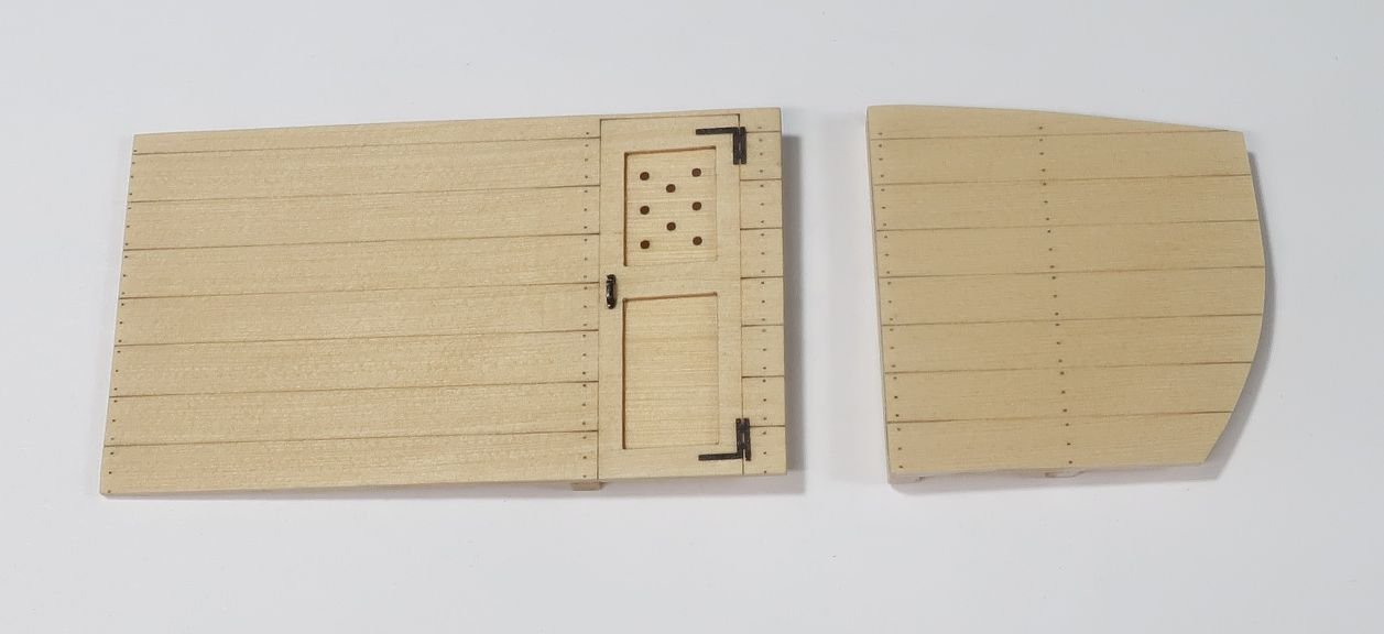
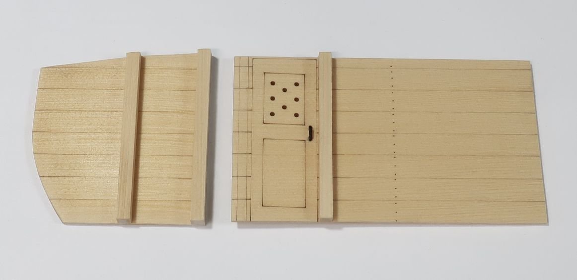
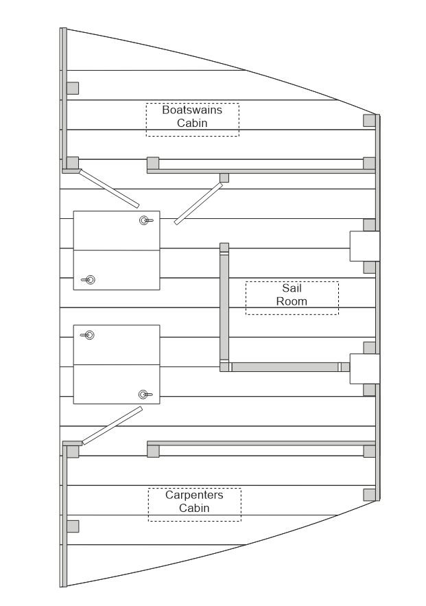
Starting chapter 7 The first thing I wanted to do, just to get it out of the way...was to get all the gundeck beams made. I cleaned the char off of all 11 beams now. Then they were cut to length using the plans as a guide. I also used the plans to establish where each deck beam is positioned. For now I will just set them aside and grab them as I need them. The last thing I wanted was to have to stop what I am doing just to clean char off a beam and cut it to length. Its a comfort knowing they are all done and ready. The photo below shows all the beams just resting on the deck clamp. This allowed me the opportunity to cut all the templates and see what the planking scheme would look like so I can adjust it now rather than later. I think its a good plan as is...and I wont make any adjustments, yet. With the beams all ready and at hand, I could start making the cabins on the lower platform at the bow. Each bulkhead will be made in two layers. Both are 1/32" thick and are laser etched with a bunch of reference lines. Now it would be easy enough to make these from scratch but this does make the building process quicker. Especially since very little of these will be seen. Below are the sections for the carpenters cabin on the starboard side. It shows both sides. I cleaned the char from the inside edges of the door panels and then glued up each layer. Before I add any details I made sure they fit on the model. I adjusted them to fit nicely in position and adjusted the heights etc. This is why it is good to have those deck beams handy. You need to have the first two beams in position to get the heights correct. Once I was sure they fit on the model OK (see the deck layout for details), I started added the hinges and stanchions. First I added the upright timbers which are either 1/8" x 1/8" strips cut to length or 3/32" x 3/32" strips. The plans show which. Then I added the door handles and hinges. Make sure to add the handles on both sides of the door. And be careful to put them on the correct side based on which way the doors open. The outside view of both bulkheads completed. The interior of the carpenters cabin detailed. Finally they were glued into position on the model. I placed the side with the doors first. Just use your planking of the lower platform to position it straight and against the stanchion on the fcastle bulkhead. Then I added the smaller section along the aft edge of the platform. This will probably need the outside edge to be sanded because I laser cut them longer than needed. So adjust the side that butts up against the frames. But remember, there isnt any planking on the inboard side of the frames so it is expected to show a gap. Just get it as even and consistent as you can. The carpenters cabin and boatswains cabin completed. Note how the top of the bulkheads against the deck clamp are flush with the top of the deck clamp. Next up will be the sail room. But that needs to be built a different way because of the louvered walls for ventilation. Chuck
- 779 replies
-
- 39
-
-
-
- speedwell
- syren speedwell
- (and 1 more)
-
You should be fine at the bow. I wouldnt worry about that. The gratings look fantastic. I came close to leaving them natural as well.
-
Yes thats what I figured. I usually dont have so many original drafts or contemporary sources as is the case with Speedwell. And when they are so different it makes for too many choices. LOL But she will be pretty when all finished no matter which way you choose. Chuck
- 779 replies
-
- 13
-
-
- speedwell
- syren speedwell
- (and 1 more)
-
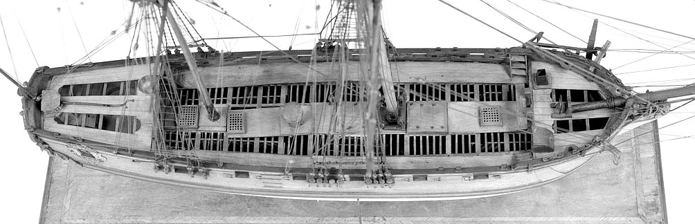
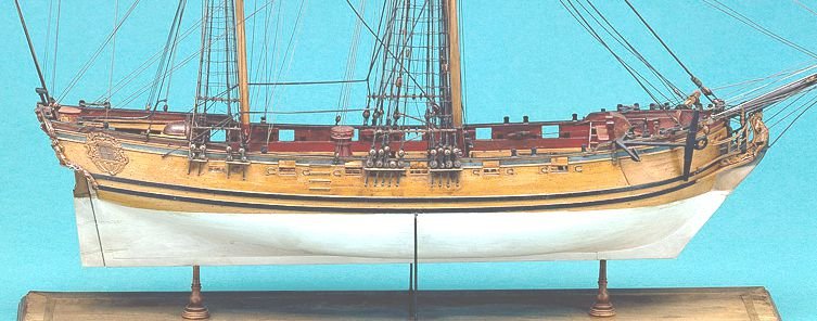
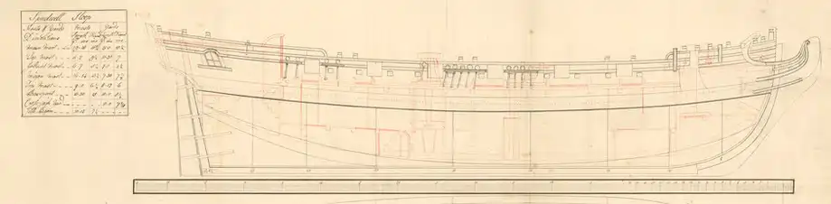
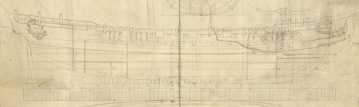
Yes indeed. I am however probably going to stick with the how the cont. model was portrayed. Its easy enough to add a few more swivel stocks for folks who want to add them. Builders choice. Aesthetically, they just ruin the elegant run of the sheer to my eye. If I were to include them however I would certainly add a rope railing with stanchions along the poop as shown on that draft detail I posted of "Fly". I think it would make sense to my eye anyway. But I am going to stick with just the few swivels mounted at the bow. I have gone with the model for so many other things.....number and position of timberheads etc. Although I have also been swayed on some other things shown on the original draft as opposed to the model. Its a trade-off. Once you start looking you will spot so many differences....between all of these primary source references. I forget how many swivels you ended up with per side. Seven or eight? The draft for Cruiser does show a heck of a lot more swivels...as shown below (bottom). Just to show folks who will build the kit and want to go another way. Cont model with two swivel stocks per side. Speedwell draft with two swivel stocks per side. Cruiser class draft with 10 swivel stocks per side. Very different appearance with the open sheer rails as well.
- 779 replies
-
- 16
-
-
- speedwell
- syren speedwell
- (and 1 more)
-
Lovely workmanship. Keep it going...slow and steady.