George-JK
-
Posts
57 -
Joined
-
Last visited
Content Type
Profiles
Forums
Gallery
Events
Everything posted by George-JK
-
Hello Harbourmaster, This is exactly the thing! WOW Now I can move forward a bit on the build again. Thank you very much! Cheers, George
- 90 replies
-
- 1
-

-
- fairmount alpine
- billing boats
- (and 1 more)
-
Hi Rob, Mark @Rob: Thank you for the link, the stanchions from the second link look exactly right. Many thanks! Even if they are slightly off, it will be fine, as long, as they have the correct shape,which they do. @Mark: Many thanks for your build images! I actually once found these pictures, and decided to go with the Fairmount as well. However I lost the link in the passage of time. So thank you for posting the link here. Cheers, George
- 90 replies
-
- 1
-
-
- fairmount alpine
- billing boats
- (and 1 more)
-
Hi, thank you for the suggestion! Can you send me, post here a detail of the stanchion? Also how tall are they, the ones I used are 14mm 3hole ones, if these are similar in size, that would be perfect. Thanks! Cheers, George
-
Very good looking model! I also am a big fan of IJN ships. The weathering looks awesome, much better then what I can produce. 😀 Regarding the weathering, I personally feel, it is a bit too much for a ship in service, meaning it looks more like an abandoned ship, then a ship in service. But this is just my personal opinion on the matter, never seen a ship coming back from deployment in a war, so can't comment on how rusty they are. I just go off what can be seen on modern working ships... Never the less if you like how the model looks, that is the most important thing. I don't mean to start any argument here, just my opinion on the weathering, even so I think it looks very nice, and very good job, keep at it. Maybe one question, what you use for the rigging? I build model in 1/350 scale, but never do the rigging, as I couldn't find what to use, to make it look realistic, everything I tried looked just way too thick. Looks great! Cheers, George
-
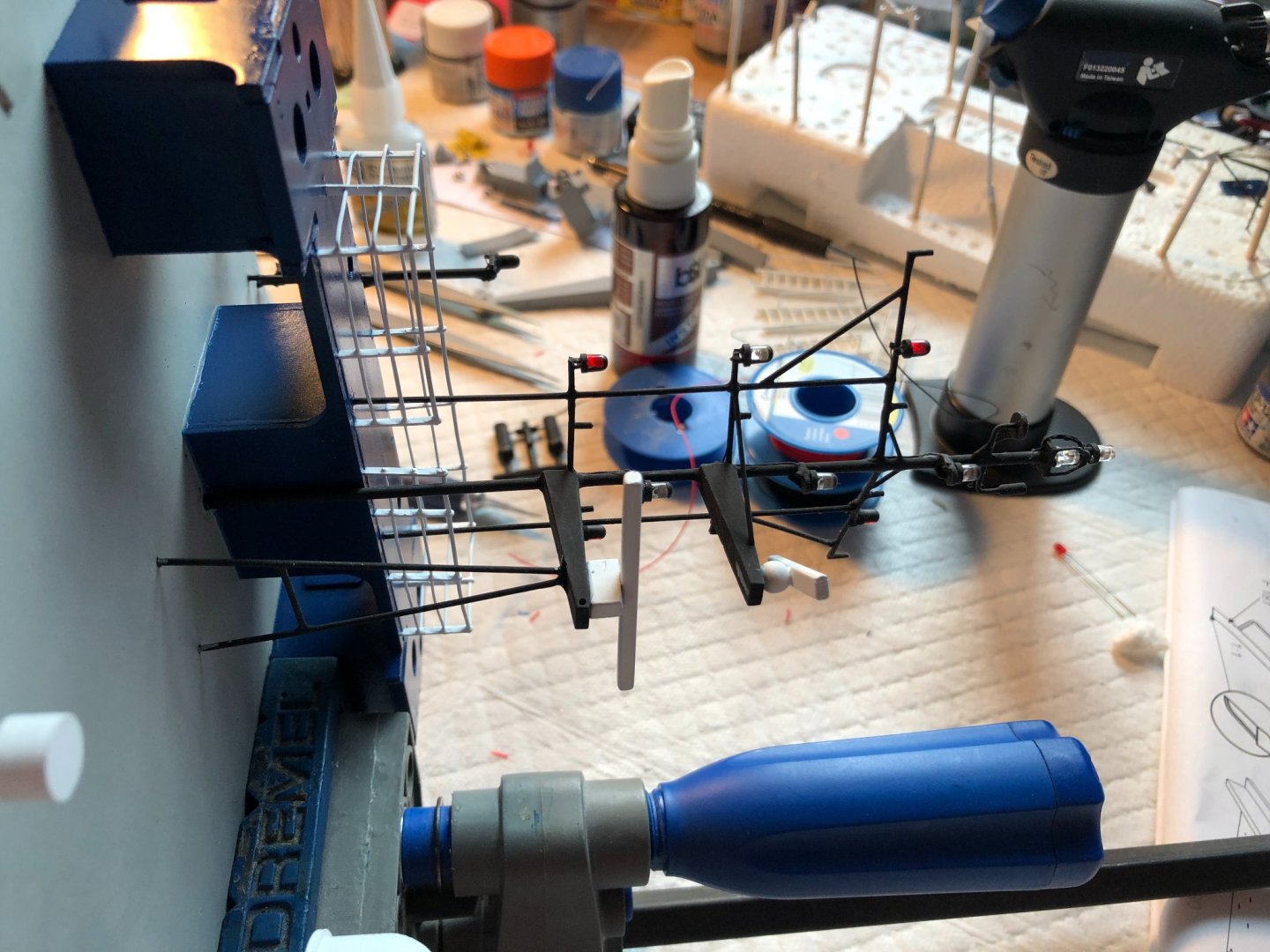
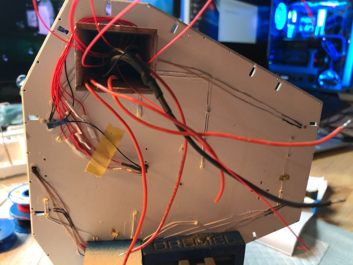
Hello All, A short update on the progress of the build. It is still ongoing, but very slow. The reason is that I miss 20 rail stanchions to finish the bridge railings, and since the Graupner, company that made the ones I used, vent bankrupt, again. There is no stock anywhere of this tipe of railing stanchions. But none the less here are a couple of progress pictures. I worked on the superstructure, assembling the main mast and the bridge roof. Gluing of the mast onto the roof, I fastened the roof in a Dremel vice top to hold it on its side. A big cable mess coming out of the mast, through the chimney down the bridge. Finished the connector soldering on all the lighting on the roof. And the "finished" superstructure. By this time I already managed to knock off the top LED once, but luckily it was a relatively easy fix. A couple of words for the intermediate conclusion. First let me mention a couple of things I found the KIT can improve upon: 1. The plans of the vessel in any part of the included building instructions, and the big plan DO NOT SHOW the picture of the LEFT SIDE of the vessel. I didn't manage to find any reasonably good pictures online, to see where to place all the details on that side of the boat. 2. Some details are not mentioned in the instructions, where they go to, presumably they are meant for the left side. But also one piece on the hull going on both sides (a stripe of wood 1x1mm by 40mm long) just appears on one detail in the plans, easy to overlook, just like it happened to me... Maybe it is me being incompetent. But I find the the instructions, for a KIT quite incomplete... I have build, successfully, the HMS Pegasus by Victory Models, yes there are master-full build logs on here featuring this model, but still, the instructions had all the necessary information to build the kit. Other issue, completely my fault is that, the model does swell in the water, I didn't correctly seal the wood. As I found out acrylic and lacquer paints do not seal the wood, who would have guessed. So whenever I sail the boat, everything, that was not epoxied swells and cracks. I should have used an enamel based primer, which would solve the problem, however it is too late for that now. That is also the reason why the build is taking so long, I don't know how to move on, as the boat, meant for being in water, can't really go in water for longer times. Cheers, George

-
Hello Jerry, I am glad to help you. Cheers,
-
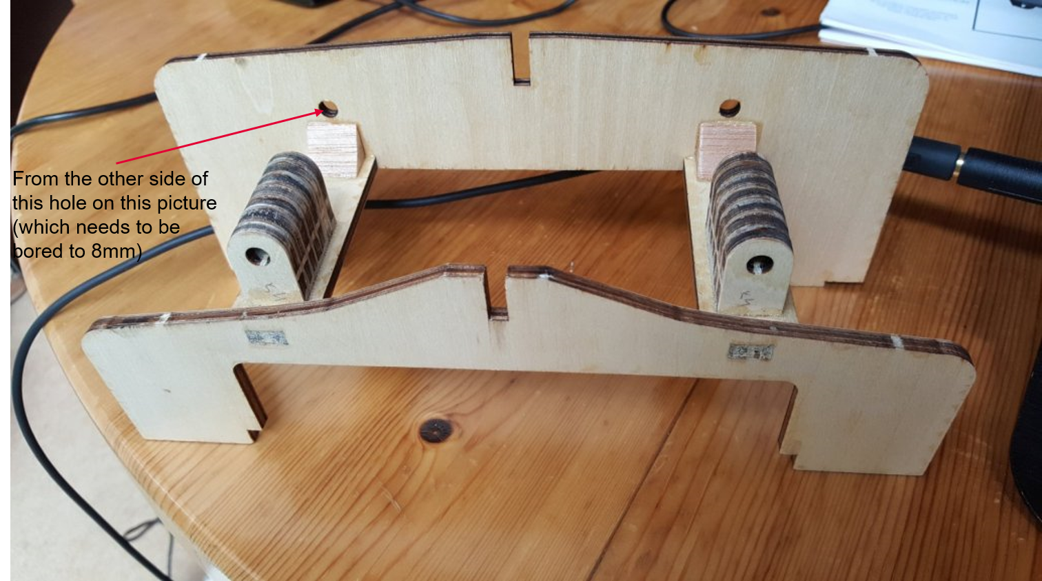
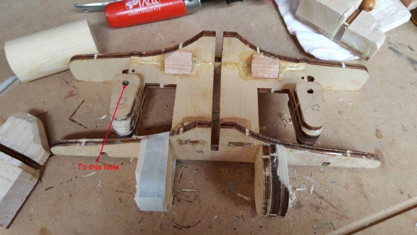
Hello Jerry, I measured the shaft, only roughly, but they seem to be the 255mm variant, which would fit their size quite well. However I suggest once you start building the stern, you do a quick measurement from the rudder shaft axis until the inner side of the wooden shaft pass-through. This would give you the minimal length of the shaft itself, without the engine flange. I think this distance is something less then 200mm, so I opted for the 255mm shafts as I was not sure how long the shaft flange is. What I mean is these two holes, naturely when the bulkheads are on the keel, properly spaced: I hope it is clear what I mean. Do not forget, all the hole, through where the shafts are going, need to be bored to 8mm if the MP Jet shafts are used. Cheers,

-
Hello Jerry, I am glad the information helped you. I understand your issues. Well at least the motor can be anything you can get in the US, the only requirement are the mounting hole placement, and the KV number (the number of revolutions per Volt, lower is better). The propshaft can be a bit more tricky, as I haven't seen anyone else do the same design, even though it is the best way to ensure that the two shafts are coaxial, motor/sropshaft. Cheers,
-
Hello Jerry, Thanks for the clarification. The "silver" joiner is a aluminium hard joint that was supplied with the propshafts. Simply they are Alu rods with 4mm hole dia and 4x M3 grub screws, two per side. They are good if the shaft-motor axes are concentric, then they are the best solution, as they minimize the noise. I think I had to drill the holes, because they are supplied in 3.2/4 mm size, typical for the intended brushed motor shaft of 3.175 mm. I believe one can get even a 4/4 mm ones in the aftermarket parts. Then regarding the motor mount itself, the bigger Alu part, is a "600" size motor flange, this is taken from the size of the standard brushed motors. This is dependent on the hole spacing of the used motor. the entire shaft assembly is build by the Czech company MP-JET, here is the link to their website with the prop shafts: https://www.mpjet.com/news/index.php/en/boat-parts/compact-boat-shafts I hope this answered your question, I am glad to be of help to you. Cheers,
-
Hello Jerry, Sorry for my late reply. I am not sure I understand what you mean by couplers. If you mean the Electronic Speed Controllers or ESCs (for big machines they are called inverters), then I used a chinese version of these ones: https://www.hobbywingdirect.com/collections/seaking-series/products/seaking-30a-v3-esc?variant=840986853 But any brushless ESC that has a forward/reverse mode should be fine. Be careful if they are sensored as many of the ECS for RC cars that have FW/REV mode are for sensored motors. They don't need to be extremely powerful for these kinds of boats (if you would be building a speedboat, that is of course a different story). I hope I understood your question correctly. So the main point would be, if the selected brushless ESC has a forward/reverse mode. Additionally if they are waterproof even better, as the brushless ones are really bad with water, know this from personal experience. Cheers,
-
@popeye the sailor The PE hand wheels are supplied by a Polish model shop super-hobby, they have multiple web addresses, depending where you live in EU, each is in that country language, I use the Austrian one, but lined is the UK shop... https://www.super-hobby.co.uk/products/Hand-wheels-1-selection.html They have quite an extensive assortment of things for plastic models. Cheers George
-
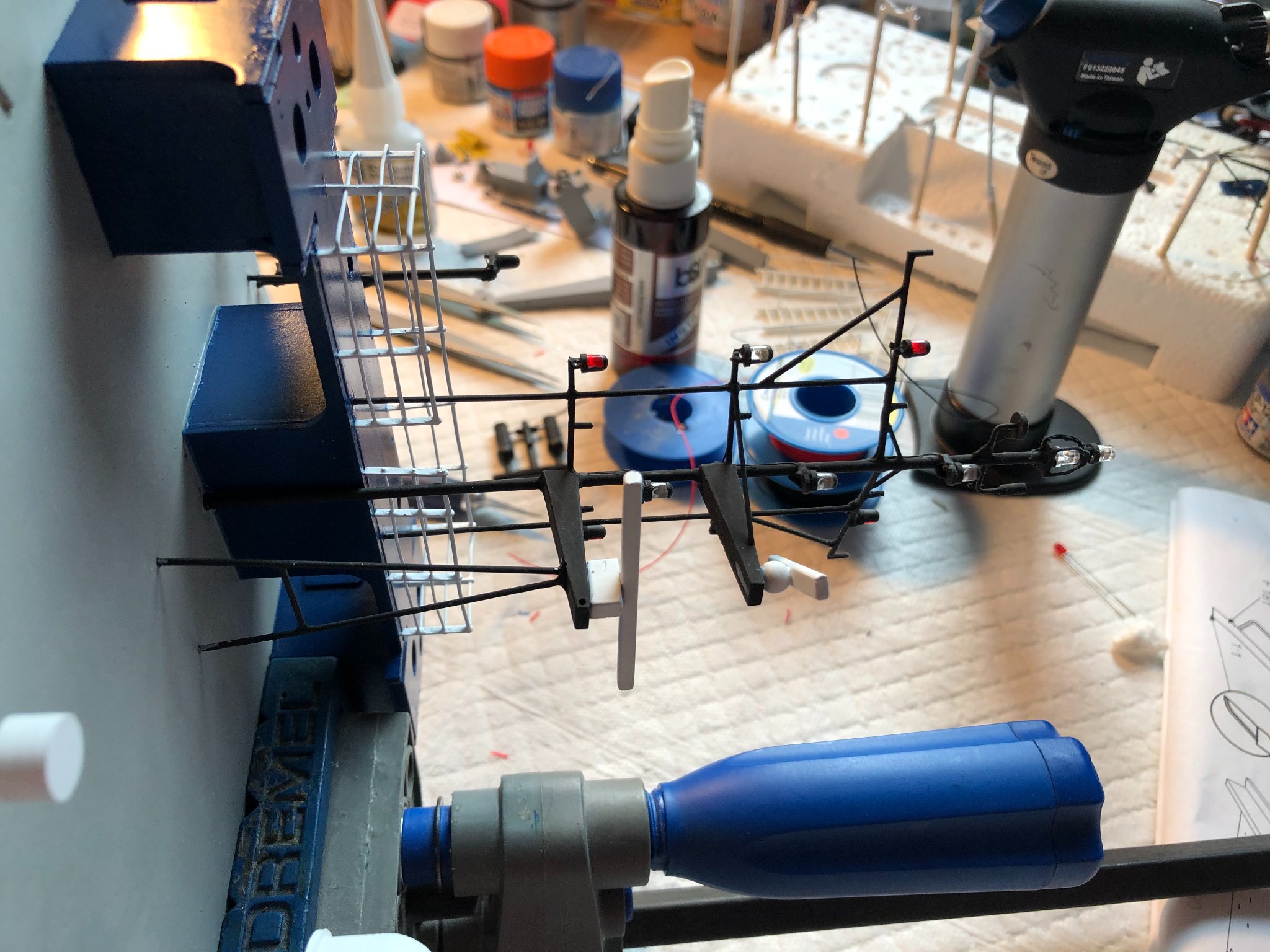
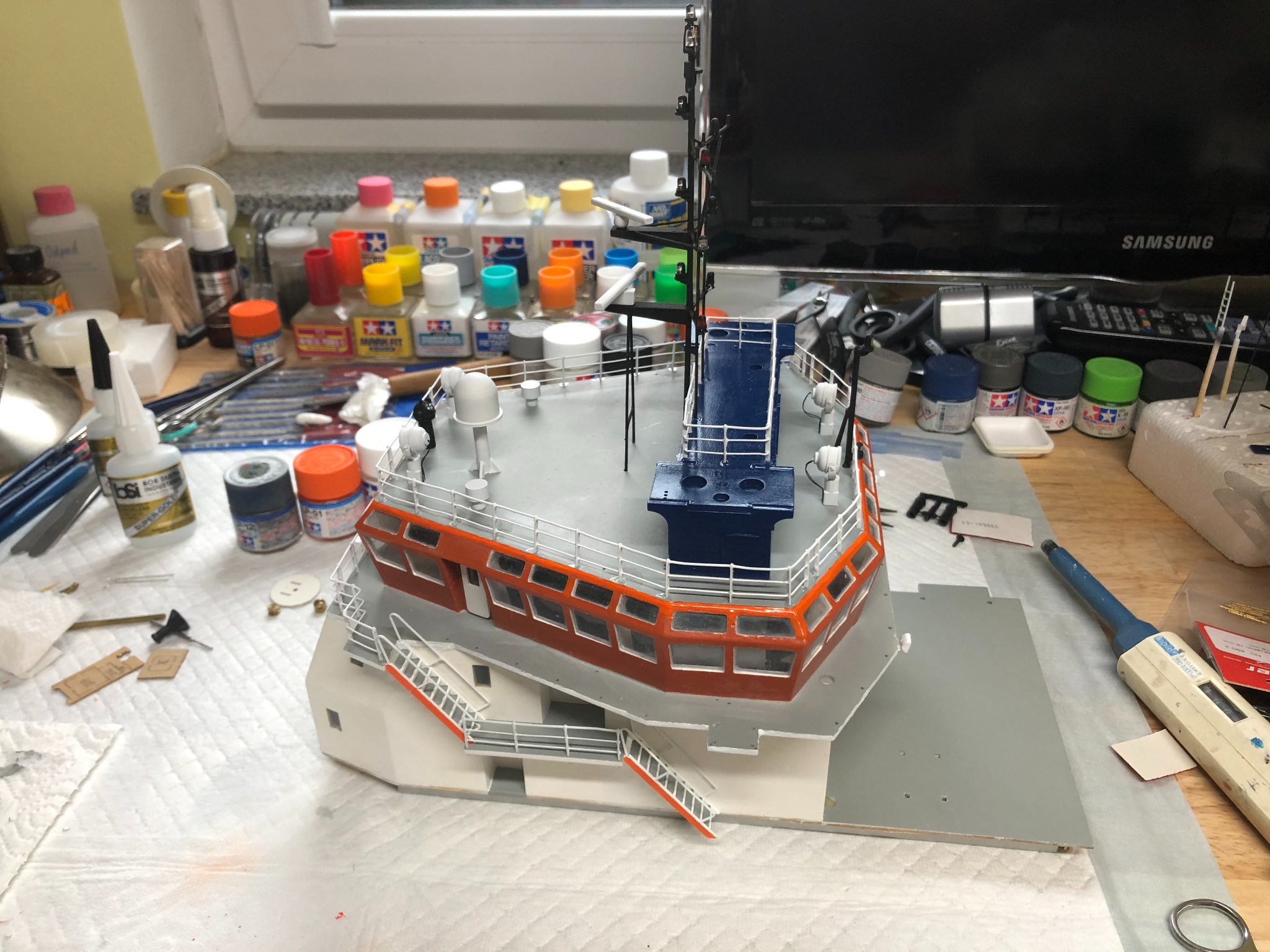
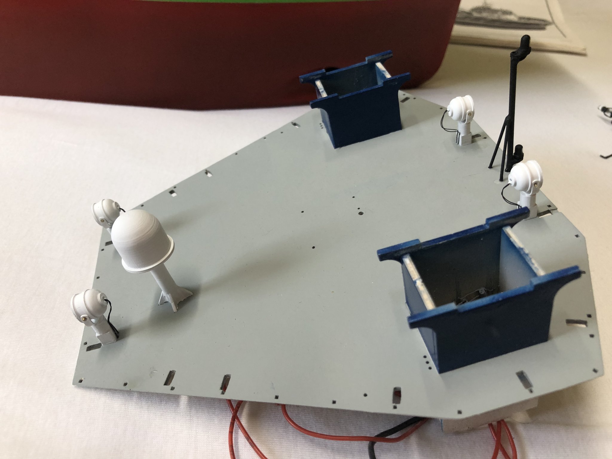
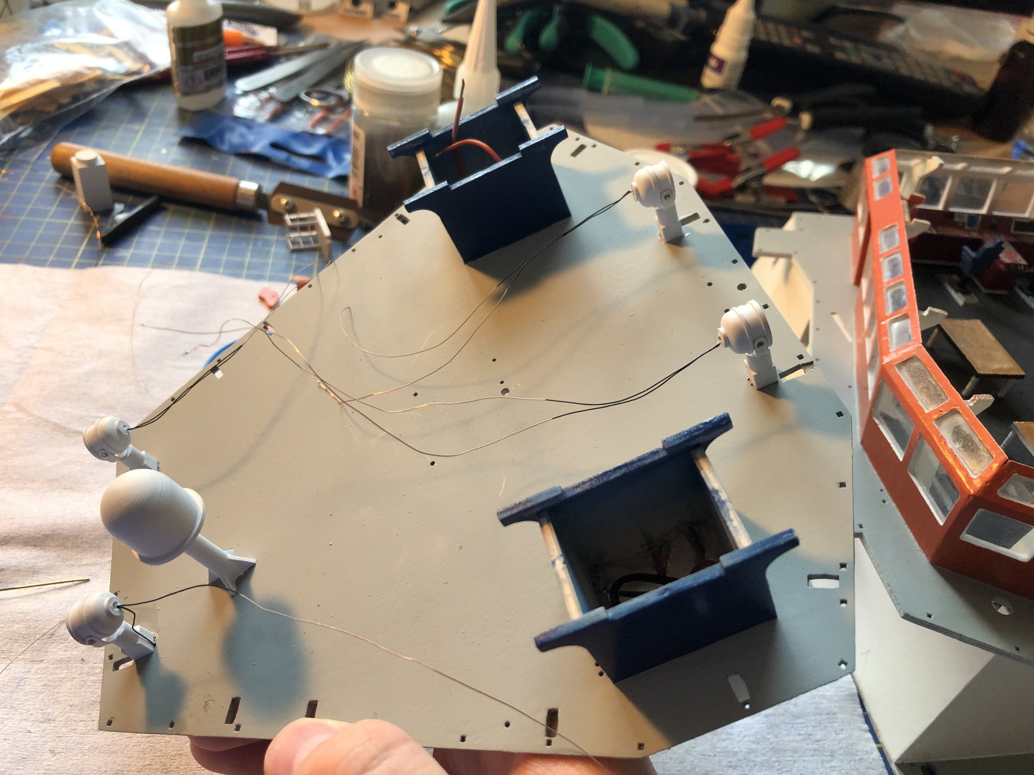
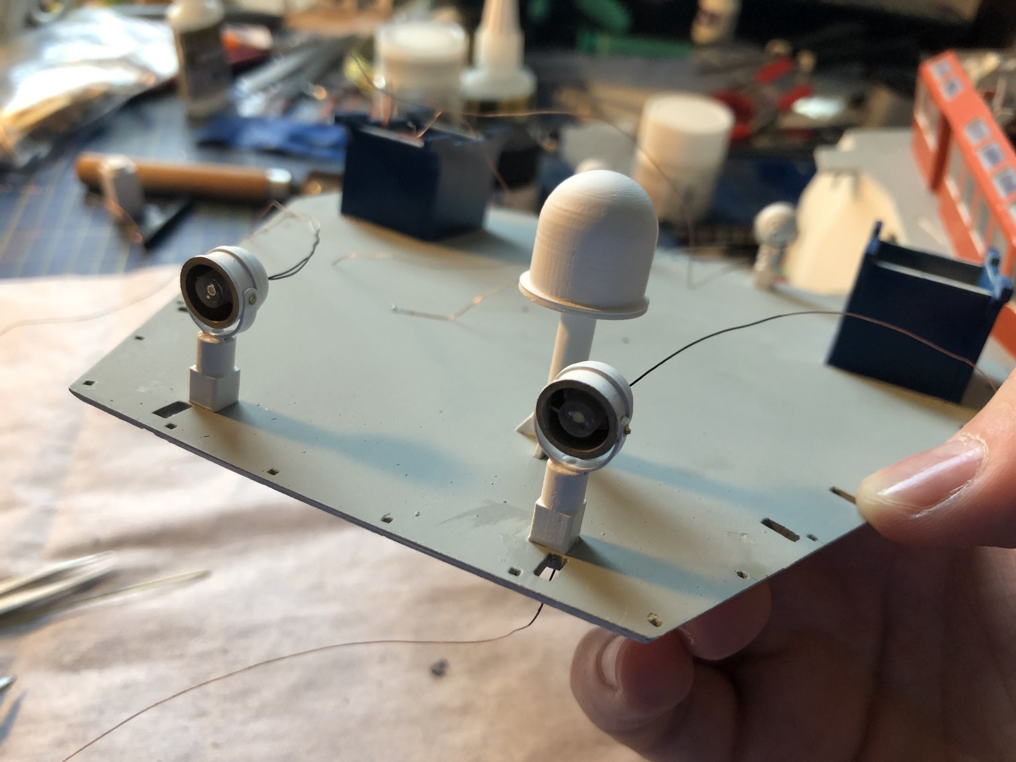
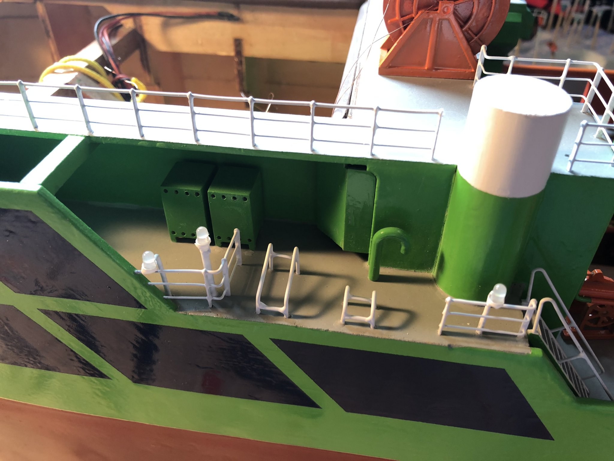
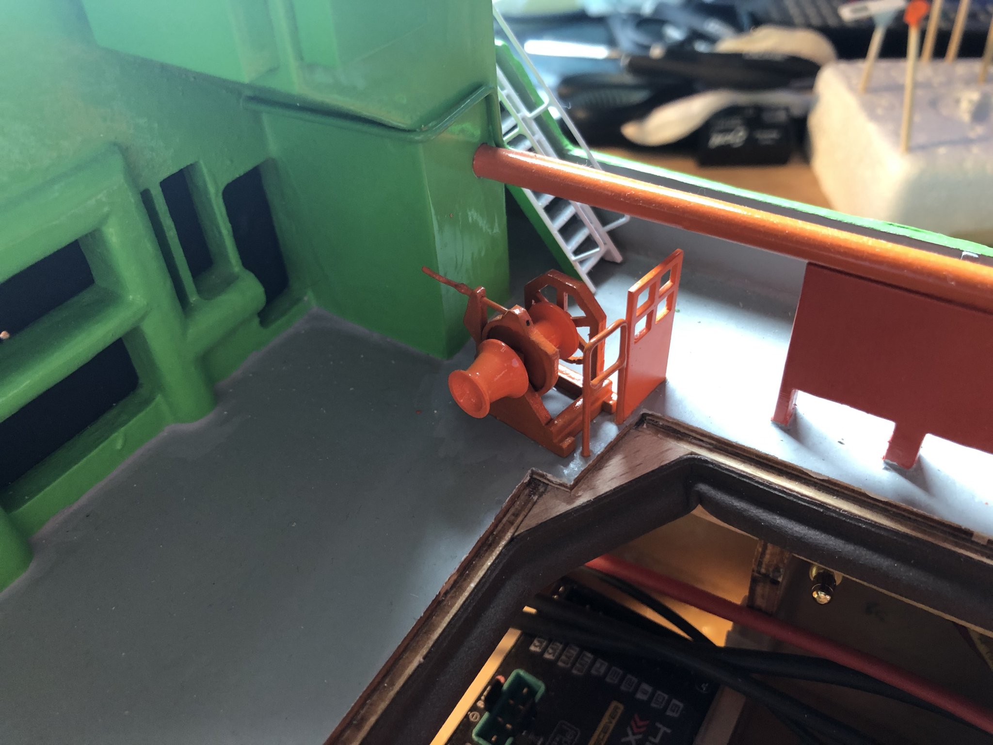
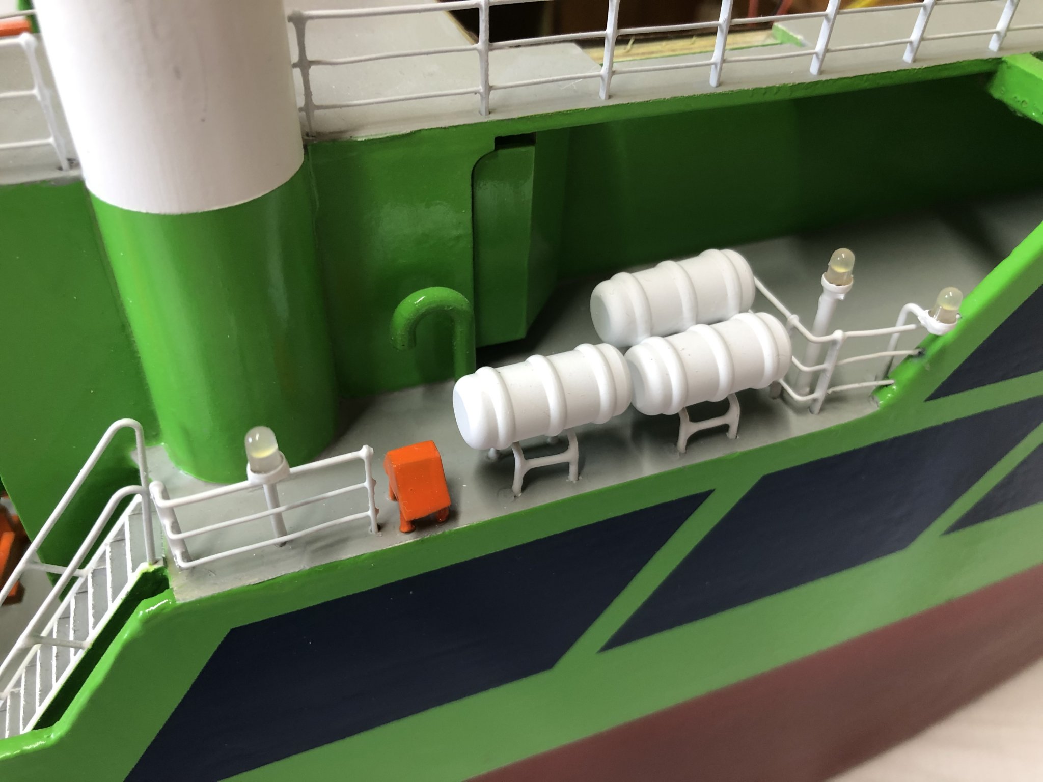
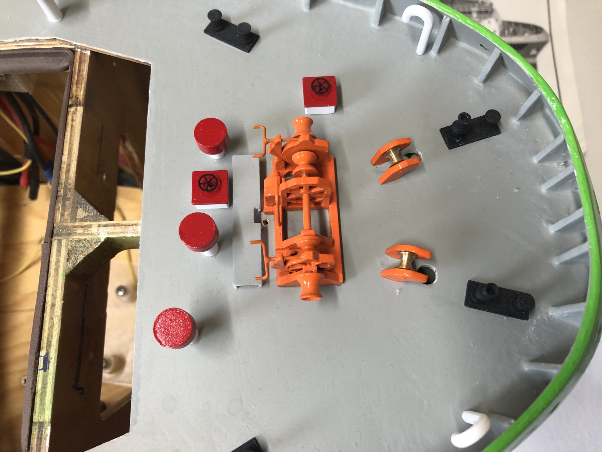
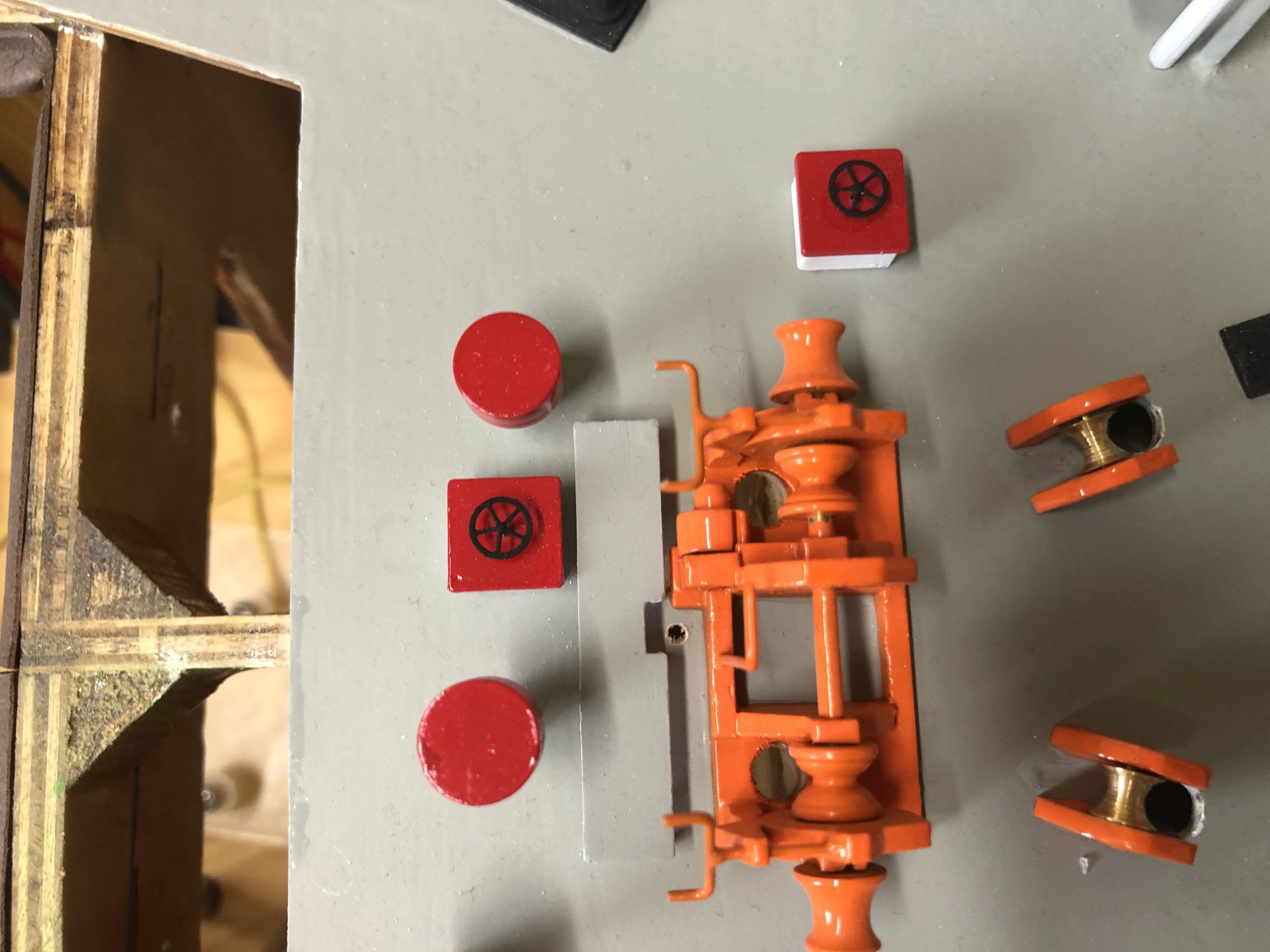
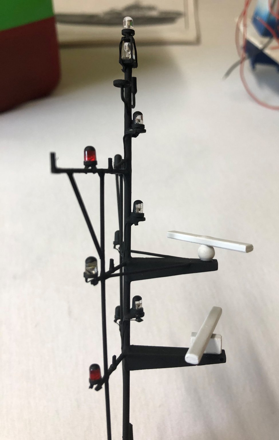
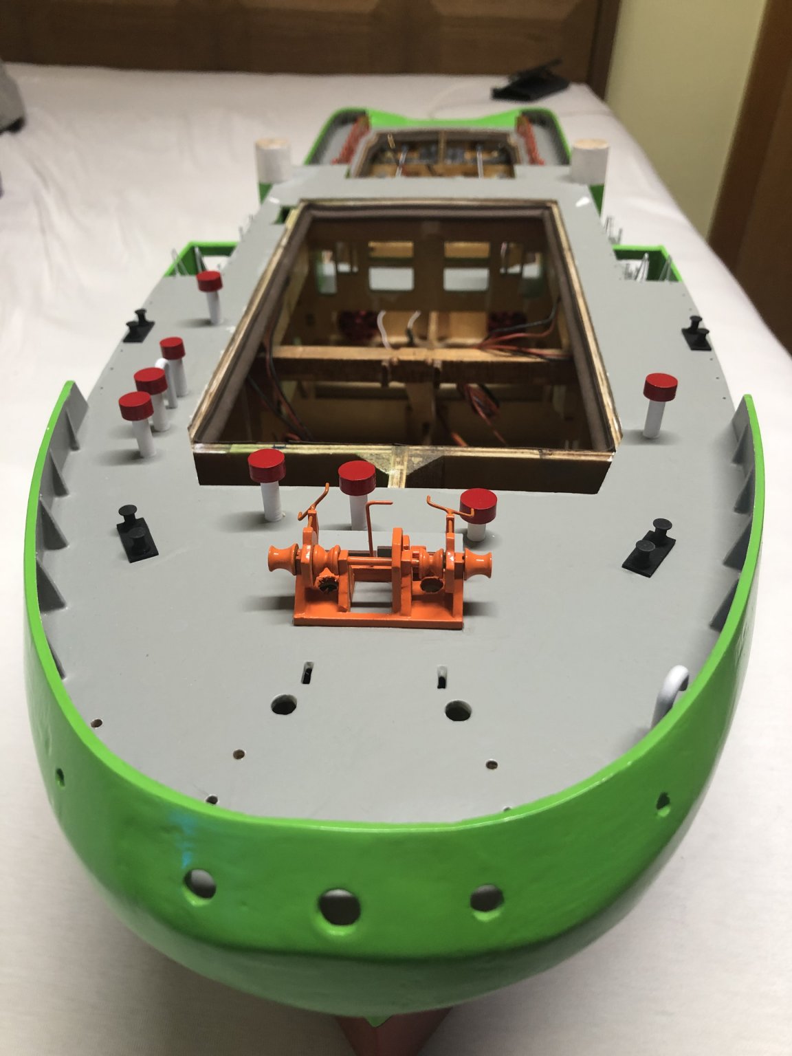
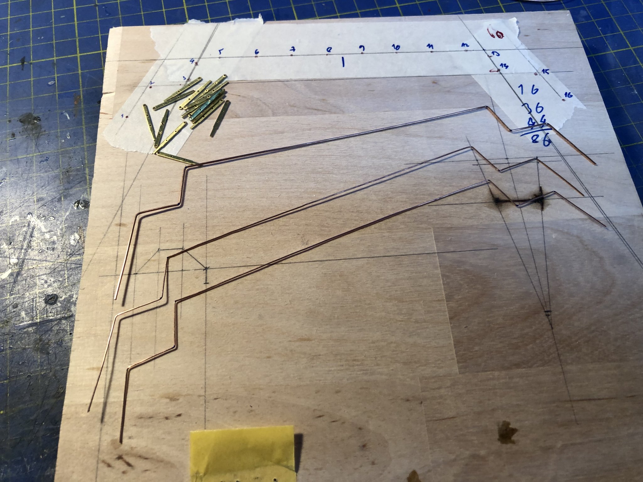
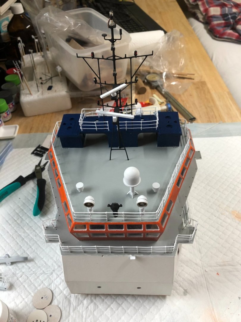
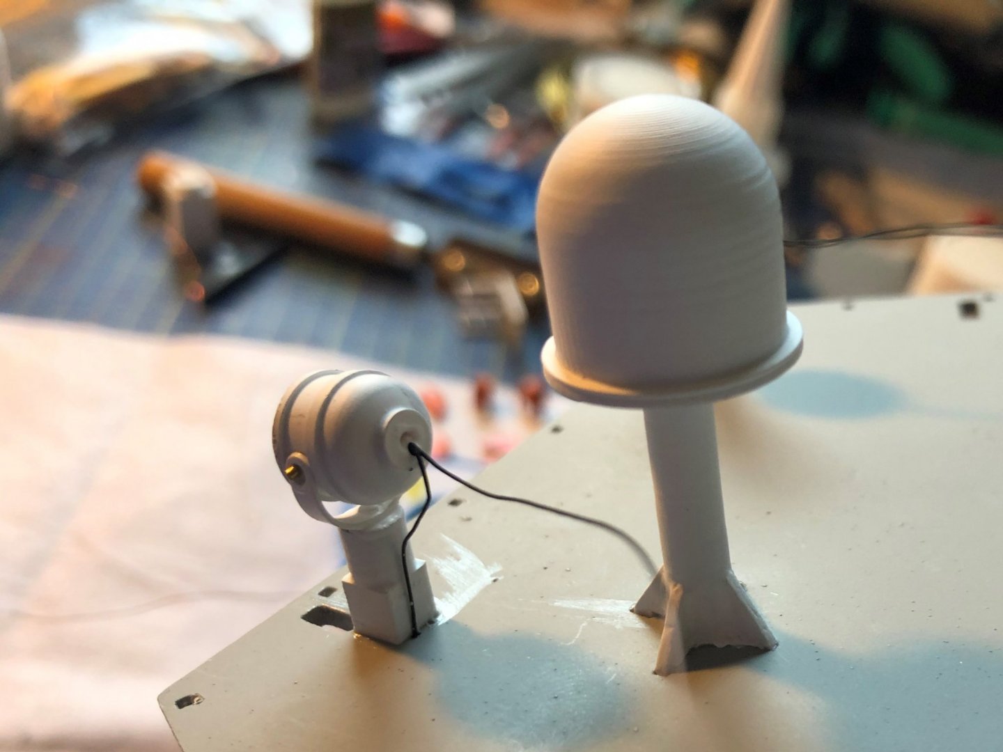
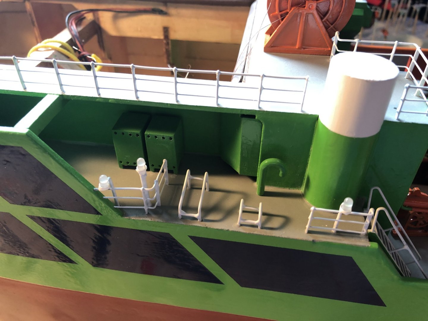
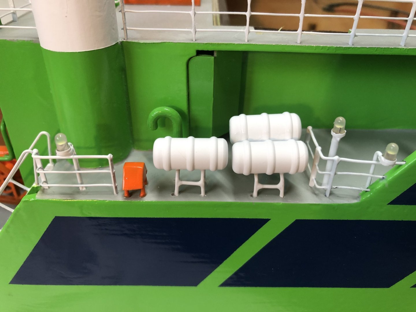
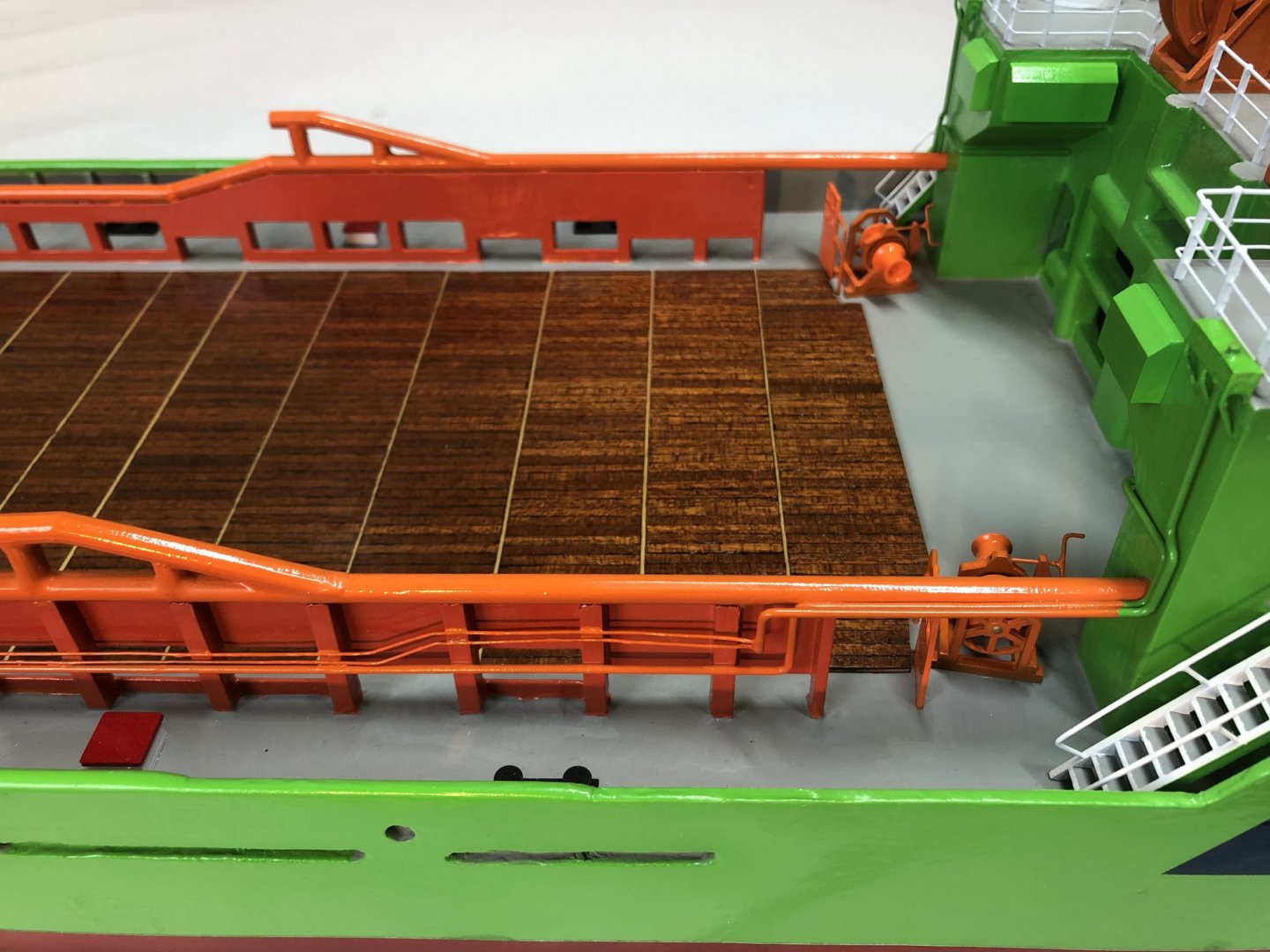
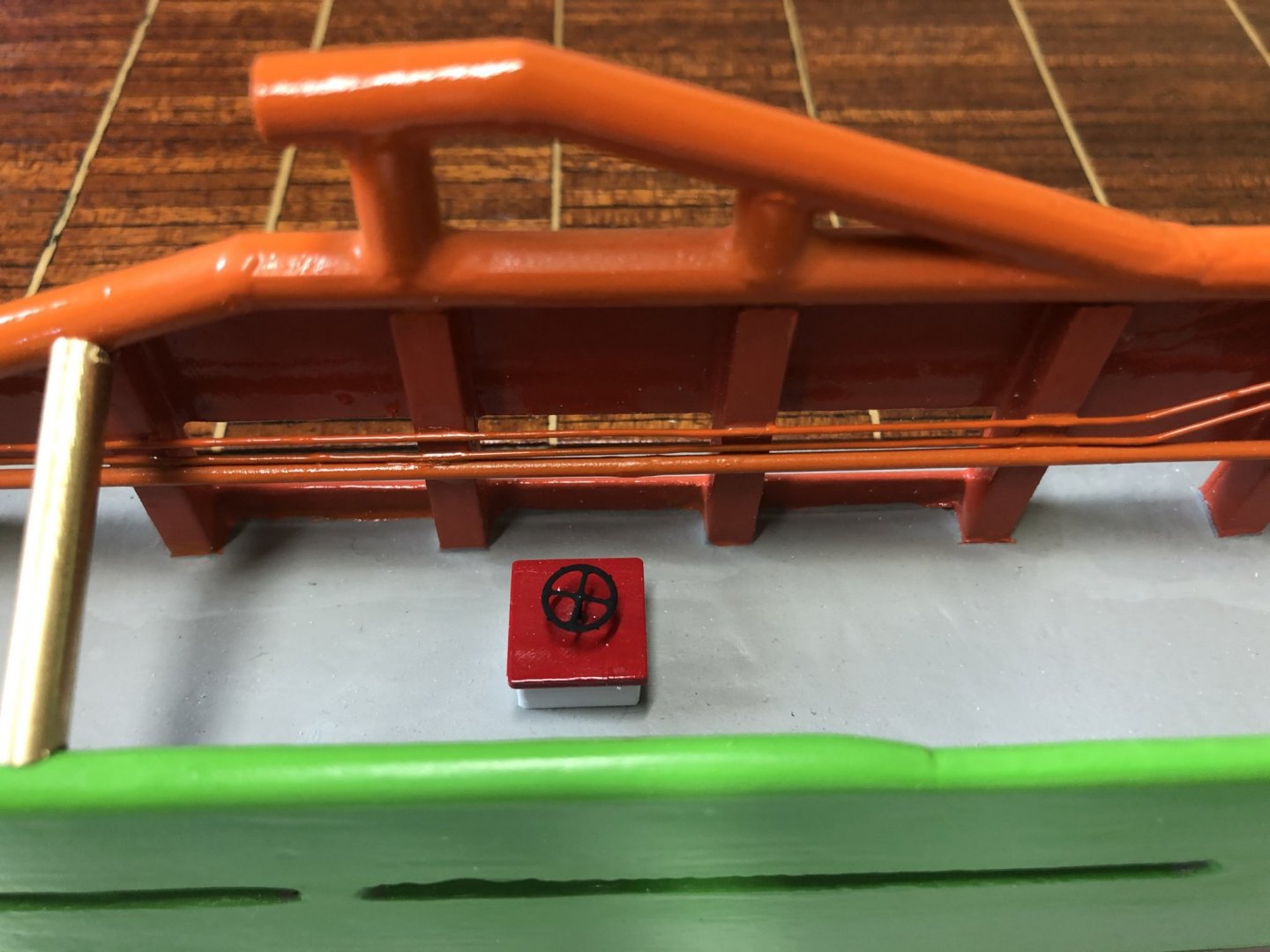
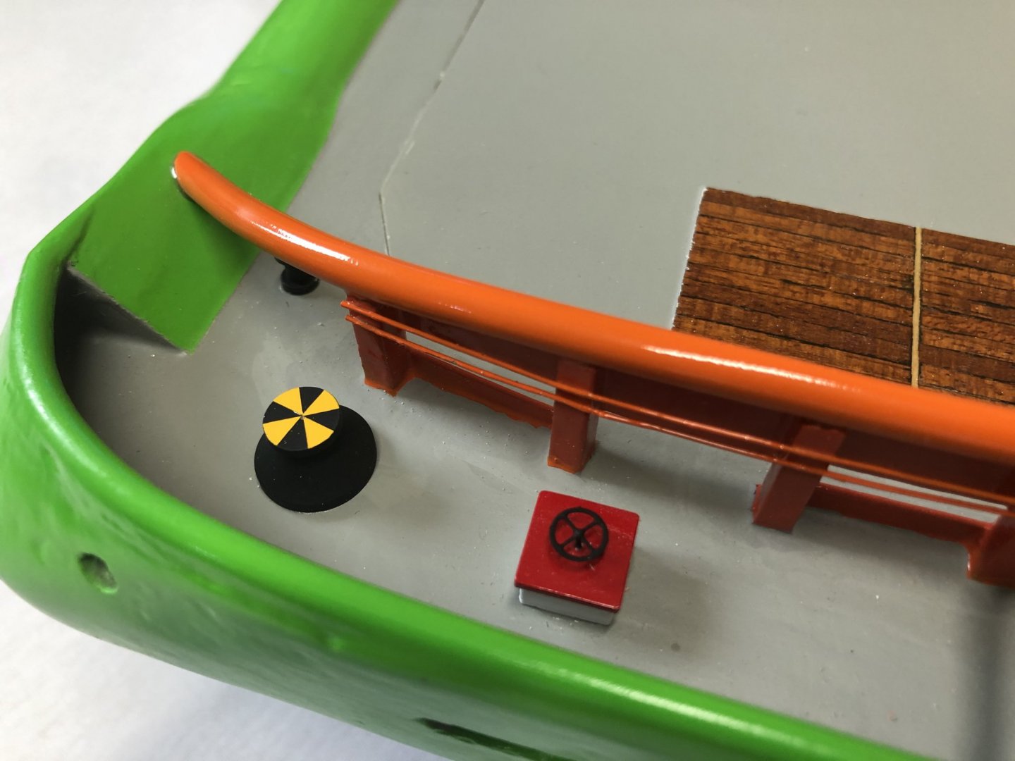
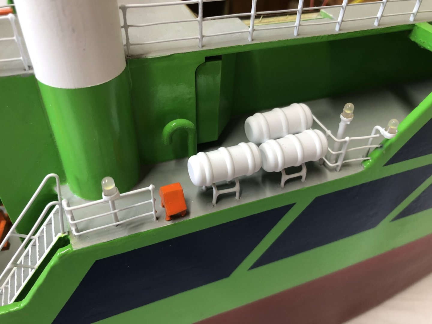
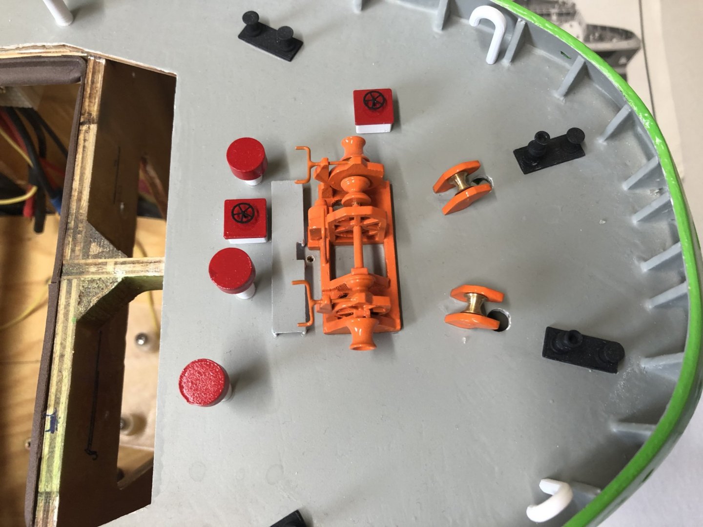
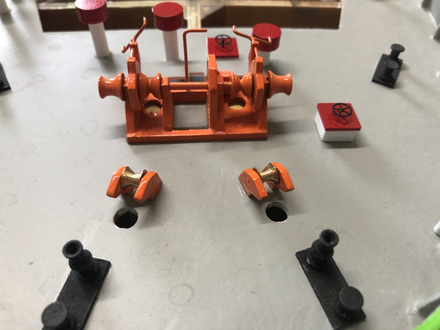
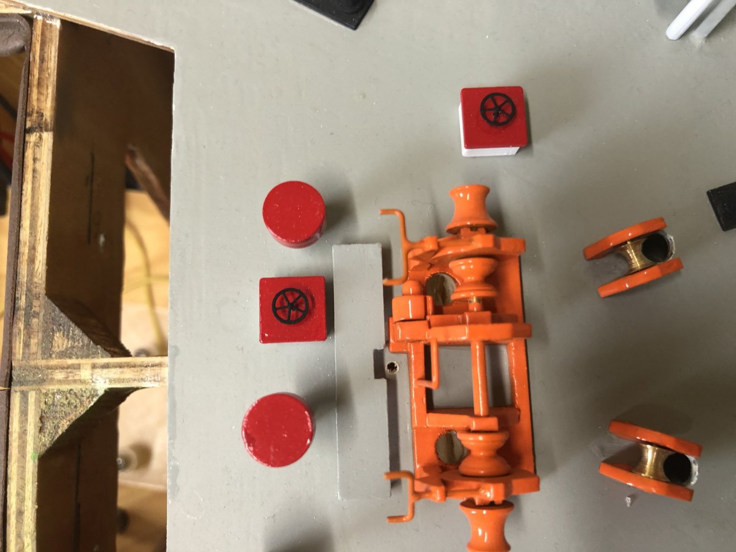
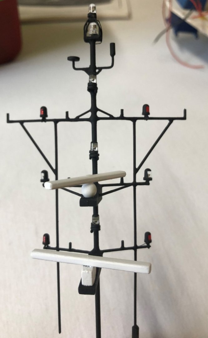
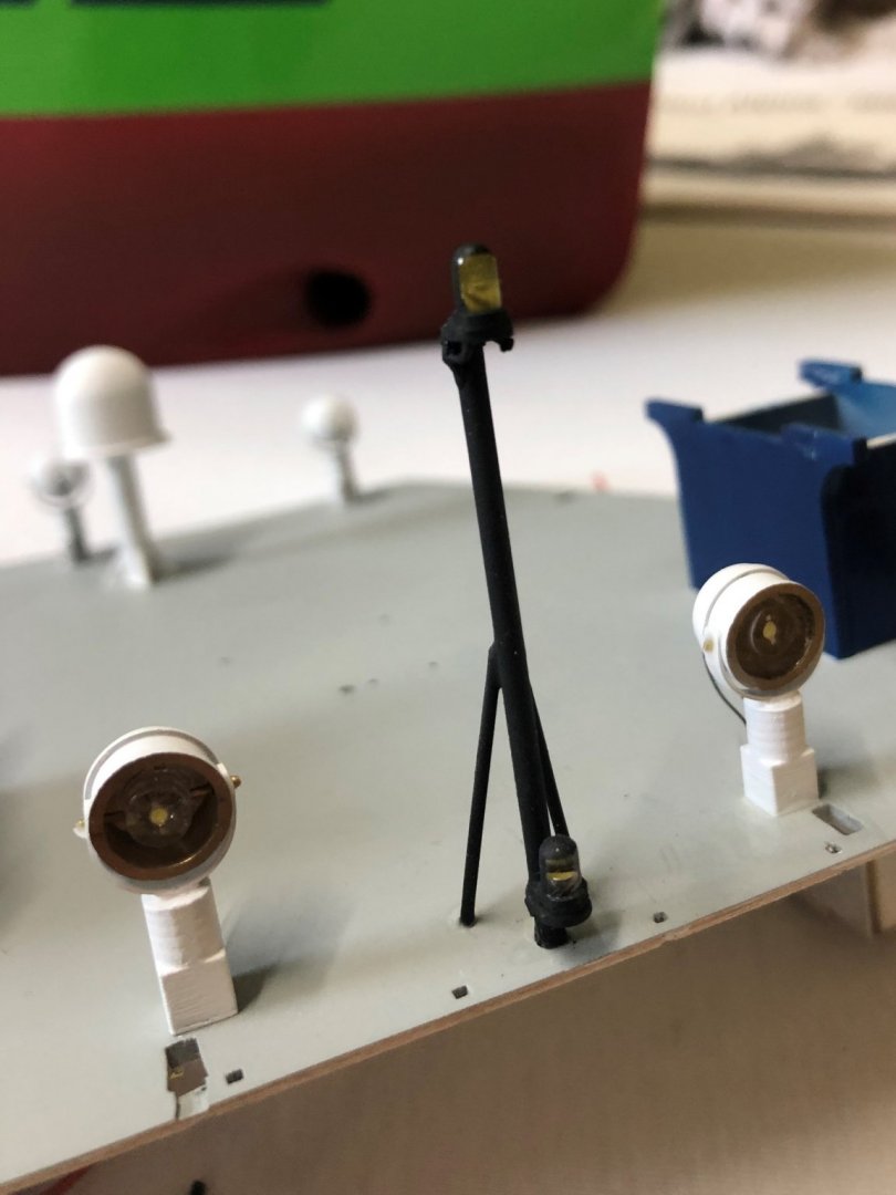
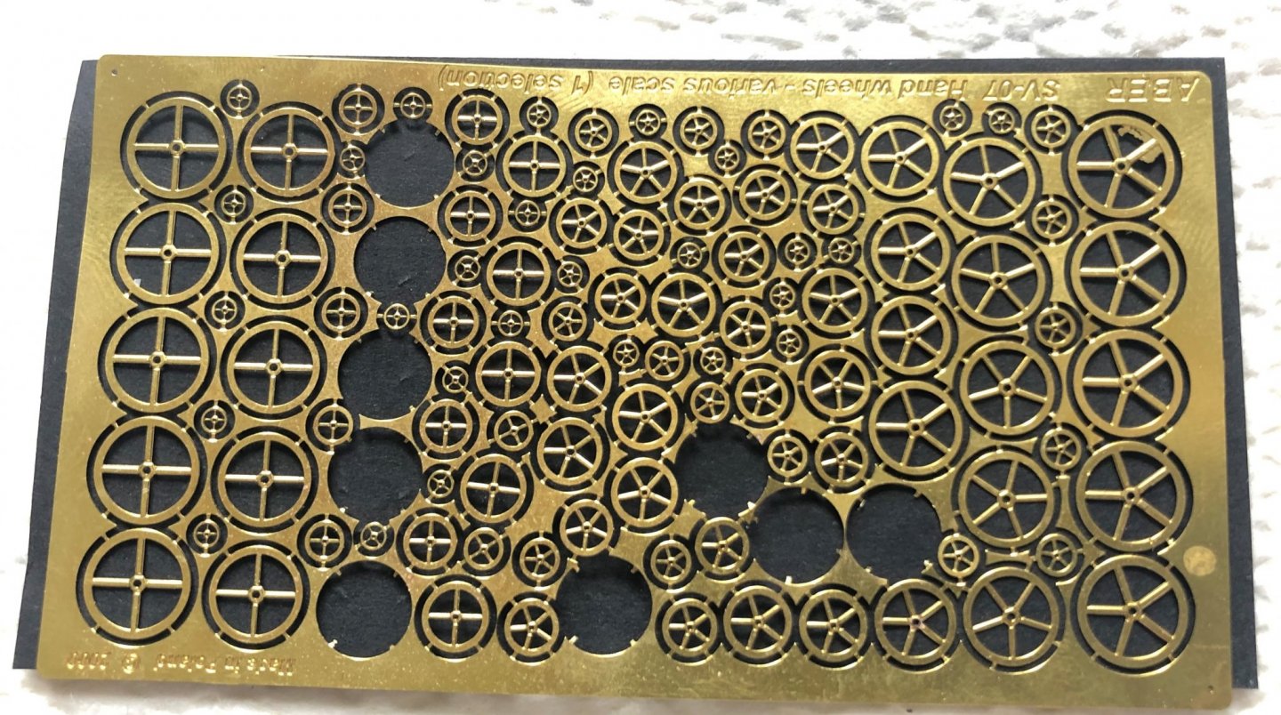
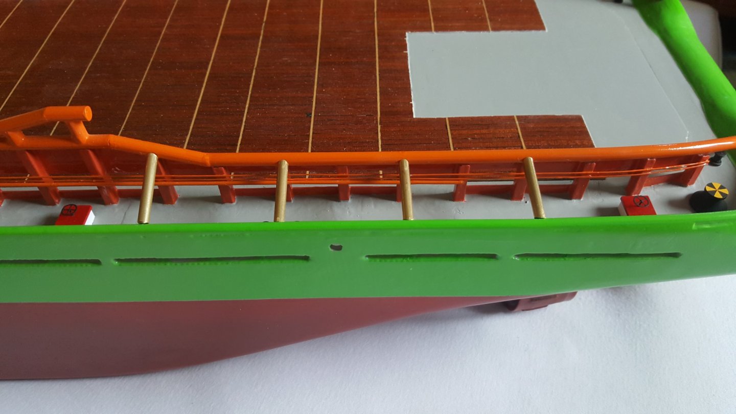
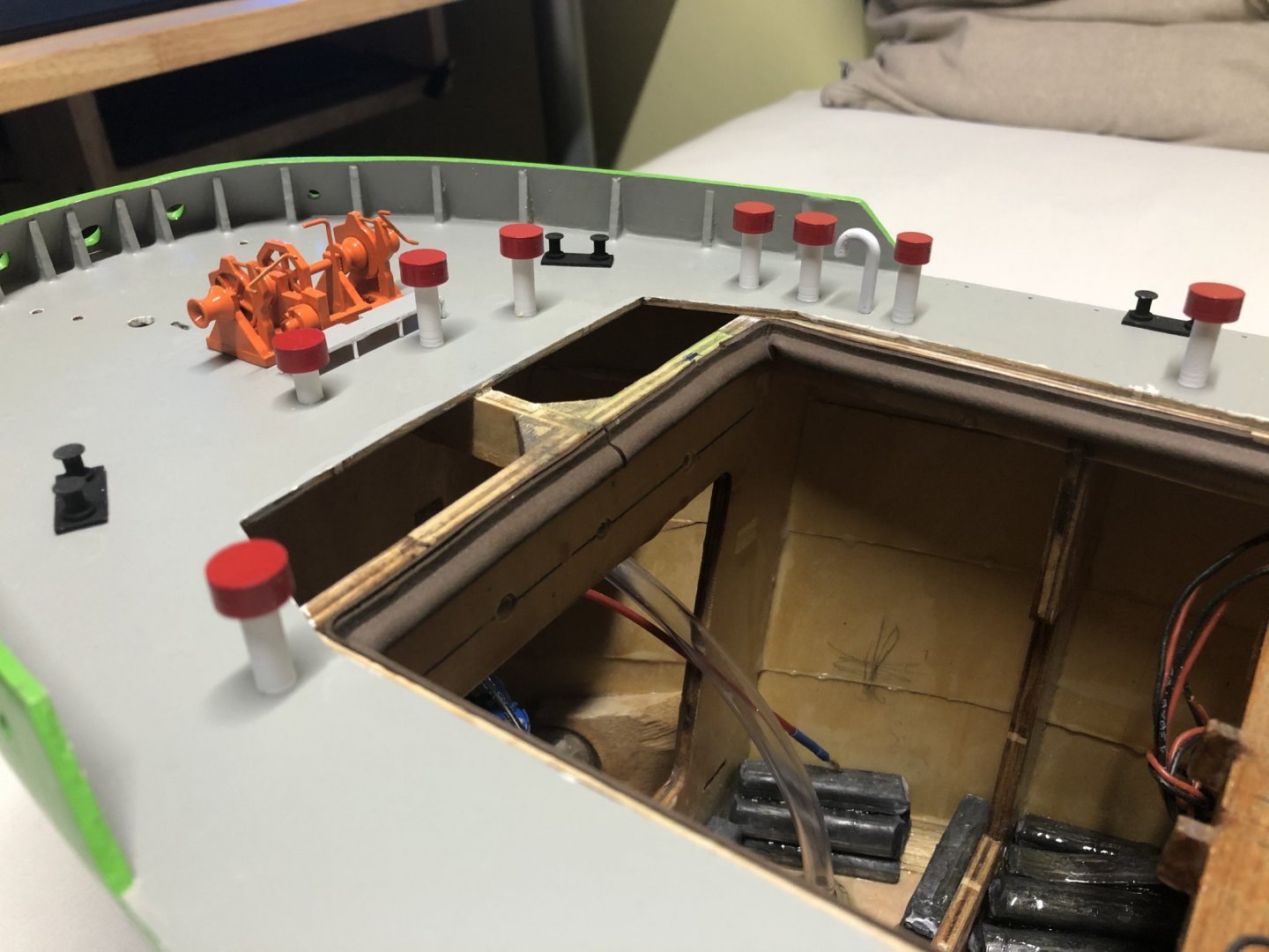
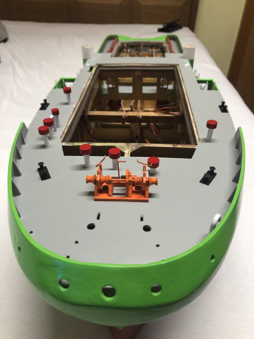
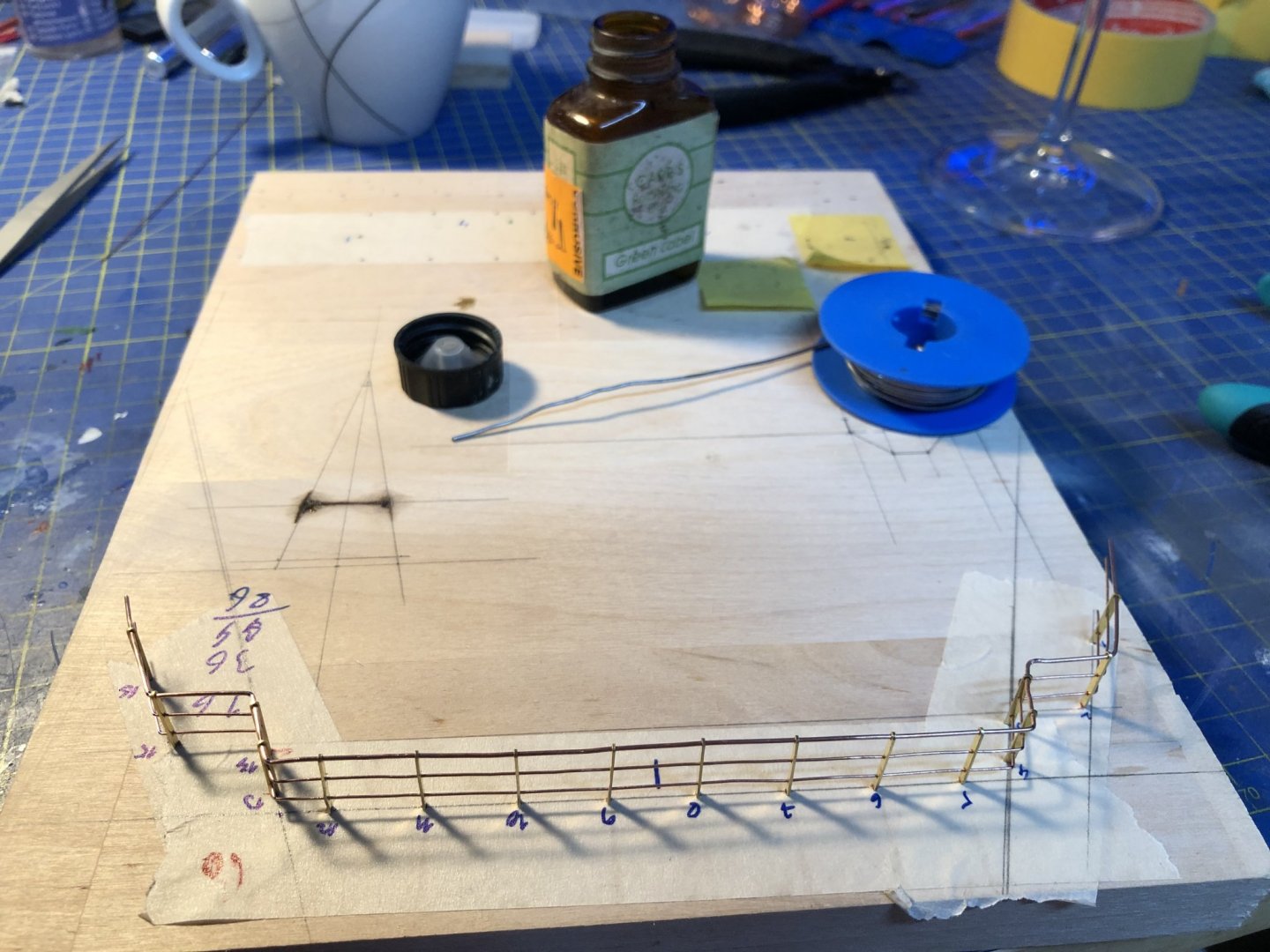
Hello All, Sorry for the long response time, I was doing some different builds for some time. In the mean time I mostly finished the hull. There should be just a couple of pieces left, that need to get pained and glued on. I added the life floats on the mid decks on both sides as well as the lights to these decks. The following picture shows the gluing of the life floats, the kit supplied ones are made of brass, they look really nice, but are terribly heavy, so I will see how long they will survive glued on with super glue... The used LEDs are some cold white 3mm diameter ones with high brightness. I will later paint their tops with silver and white, so that they don't shine just to the sky. Similar to how i did it with the mast LEDs, pictures will follow. Afterwards I added the winches and windlasses, that were still missing, as well as control wheels to the red square things on deck (no Idea of their names). For the control wheels I found a photo etched sheet with different wheel sizes and used ones that looked appropriate for the scale. Here is the photo etched sheet itself, for each size there are 5 wheels, with 4 and 5 spokes. Since I needed 6 in total, I used two 5 spoke ones for the fore deck, and four 4 spoke ones on the stern deck. Lastly the pieces that are still missing in the hull, should only be the braces between the rope guides and side rails. These are made of brass 4/3mm OD/ID tube. Originally they are to be mady from 4mm round wood stock. However I couldn't find the one supplied with the kit, probably lost it somewhere in the general mess, or just spend all of it on the stern rails, as they are also made of 4mm round sock. Nevertheless I find making them out of brass is better, as the surface finish is relatively easy, compared to making wood into smooth metal like finish. Regarding the Superstructure: I Started slowly attaching the bigger details as light, and so on. I went for simplicity and made them non movable, as that would over-complicate the build even more. The black wires are actually functional, I tried to bend them so sort of realistic shape, don't know if it passes... The main and mizzen masts are mostly finished as well. As I mentioned before, I painted the LEDs on them, to make them into the corresponding sector lights. I painted them first with a coat of silver paint, to at least reflect some of the unused light out of the LEDs in the right direction. Aftervards I pained them in a coat of black, to match the masts. I will try to post more frequently, but with the quarantine I actually have more projects ongoing, so I forget to upload here. Sorry for that. Cheers George.


- 90 replies
-
- 3
-
-
- fairmount alpine
- billing boats
- (and 1 more)
-
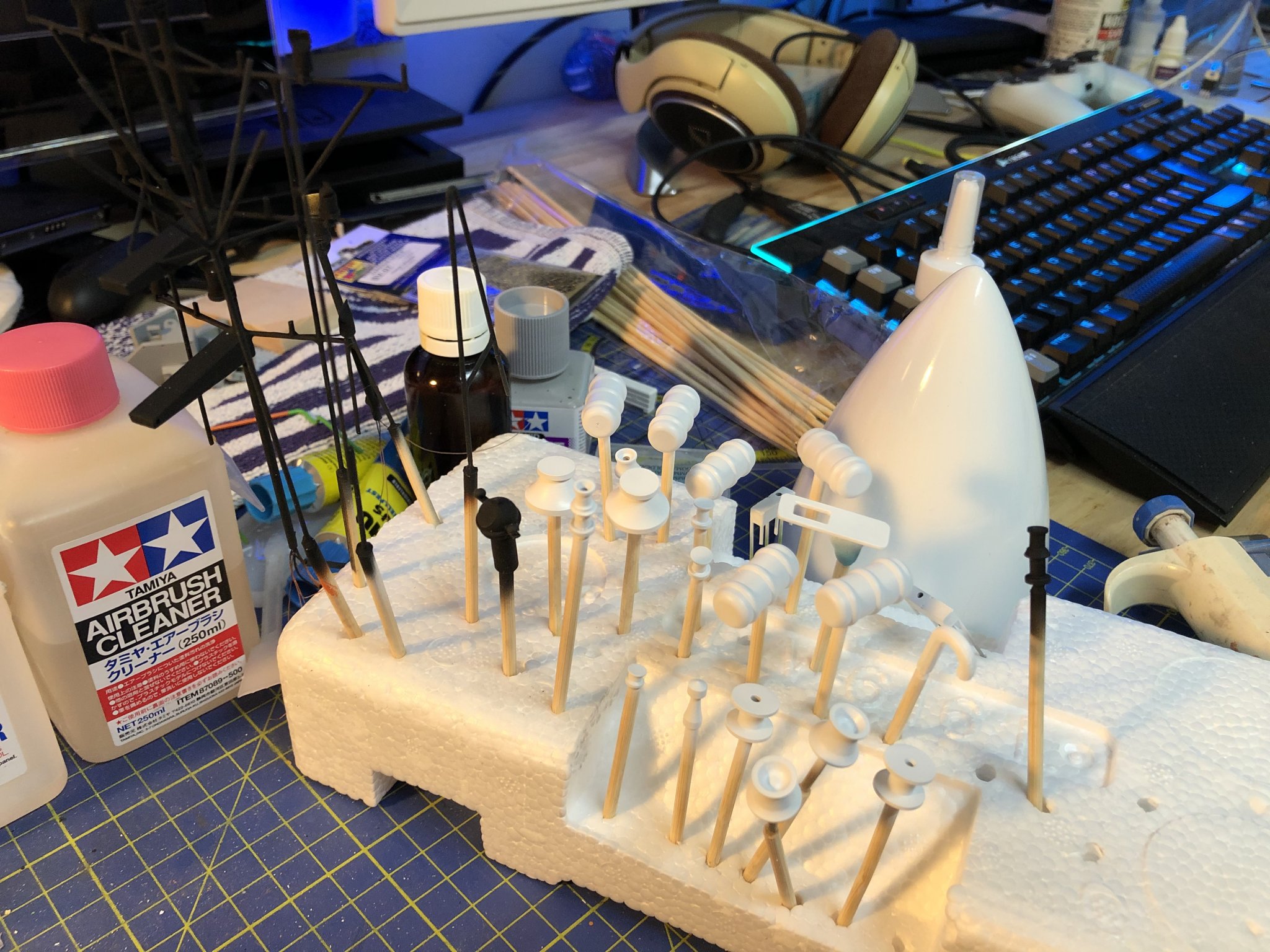
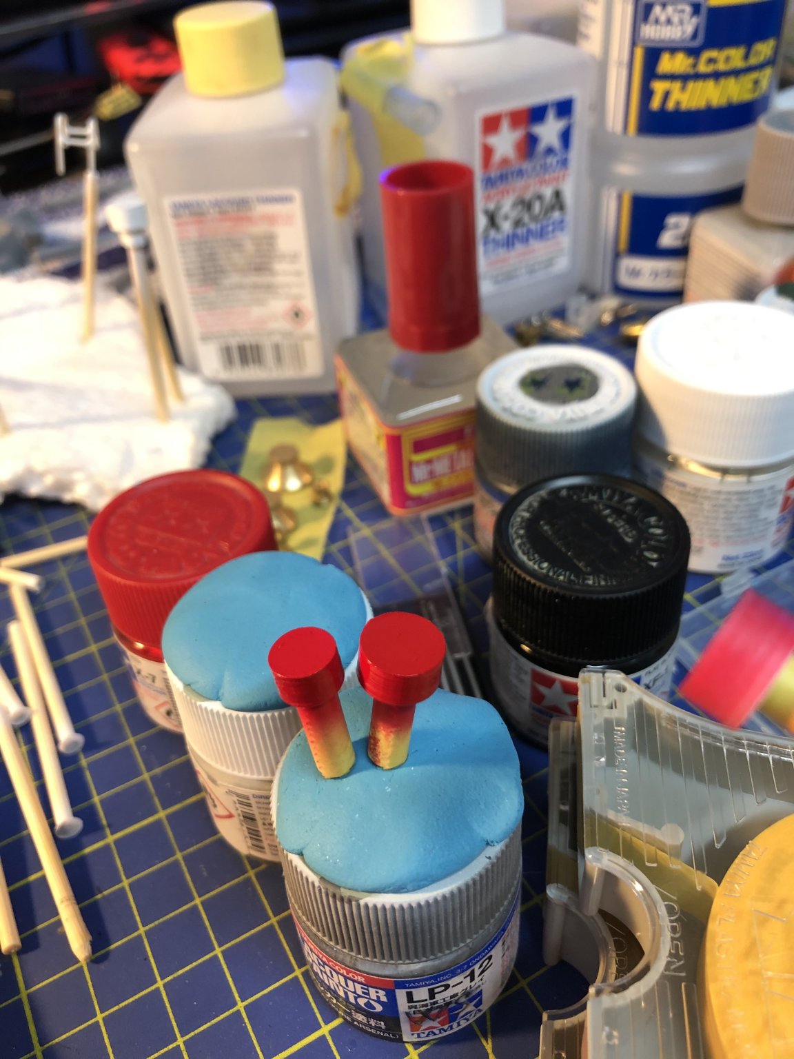
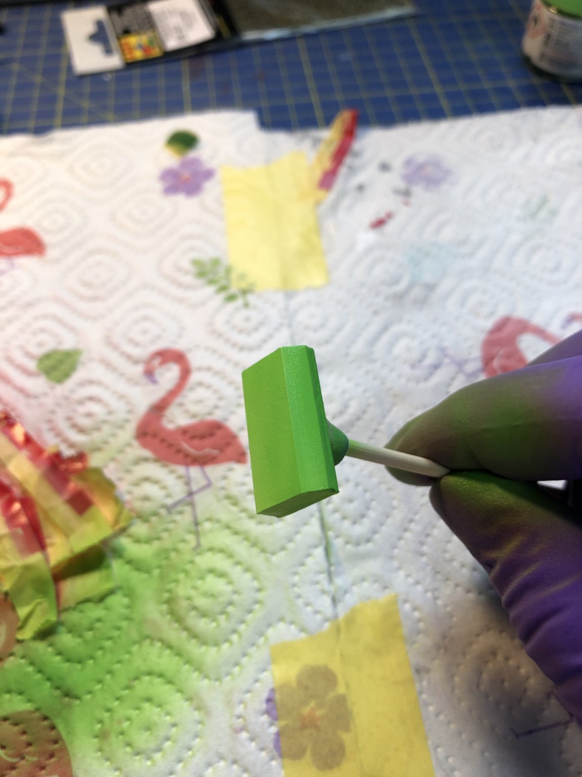
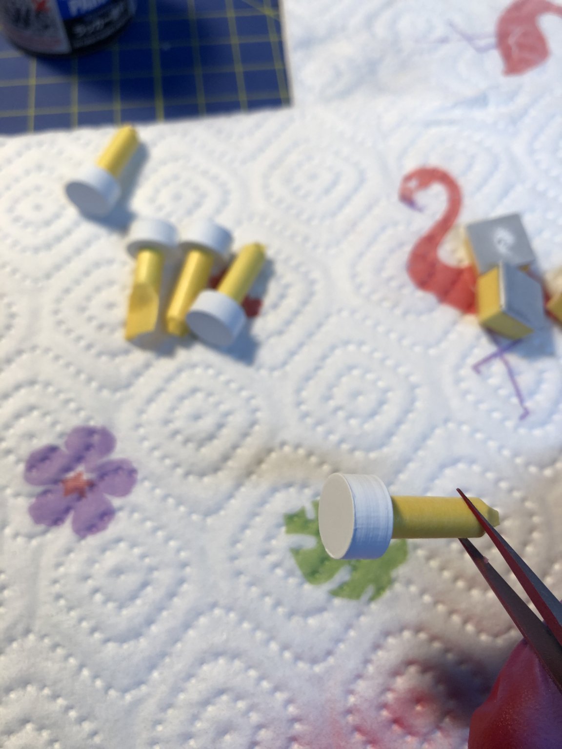
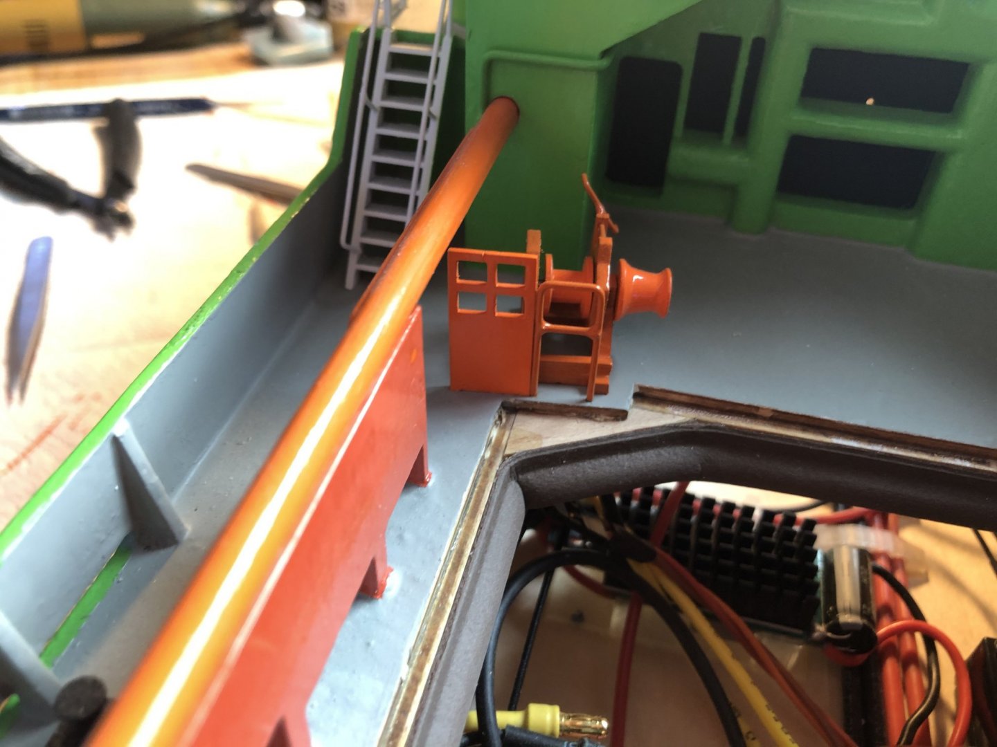
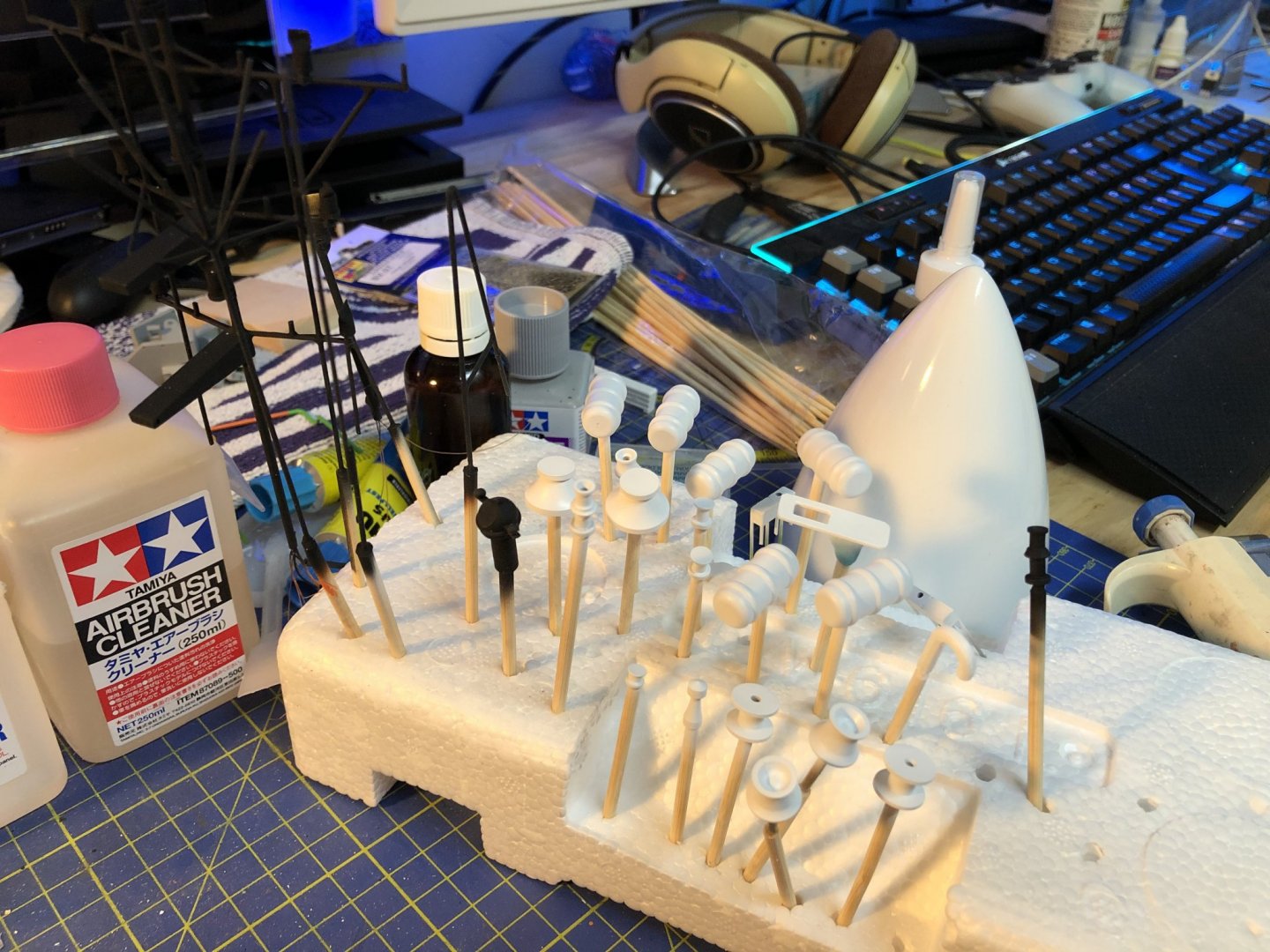
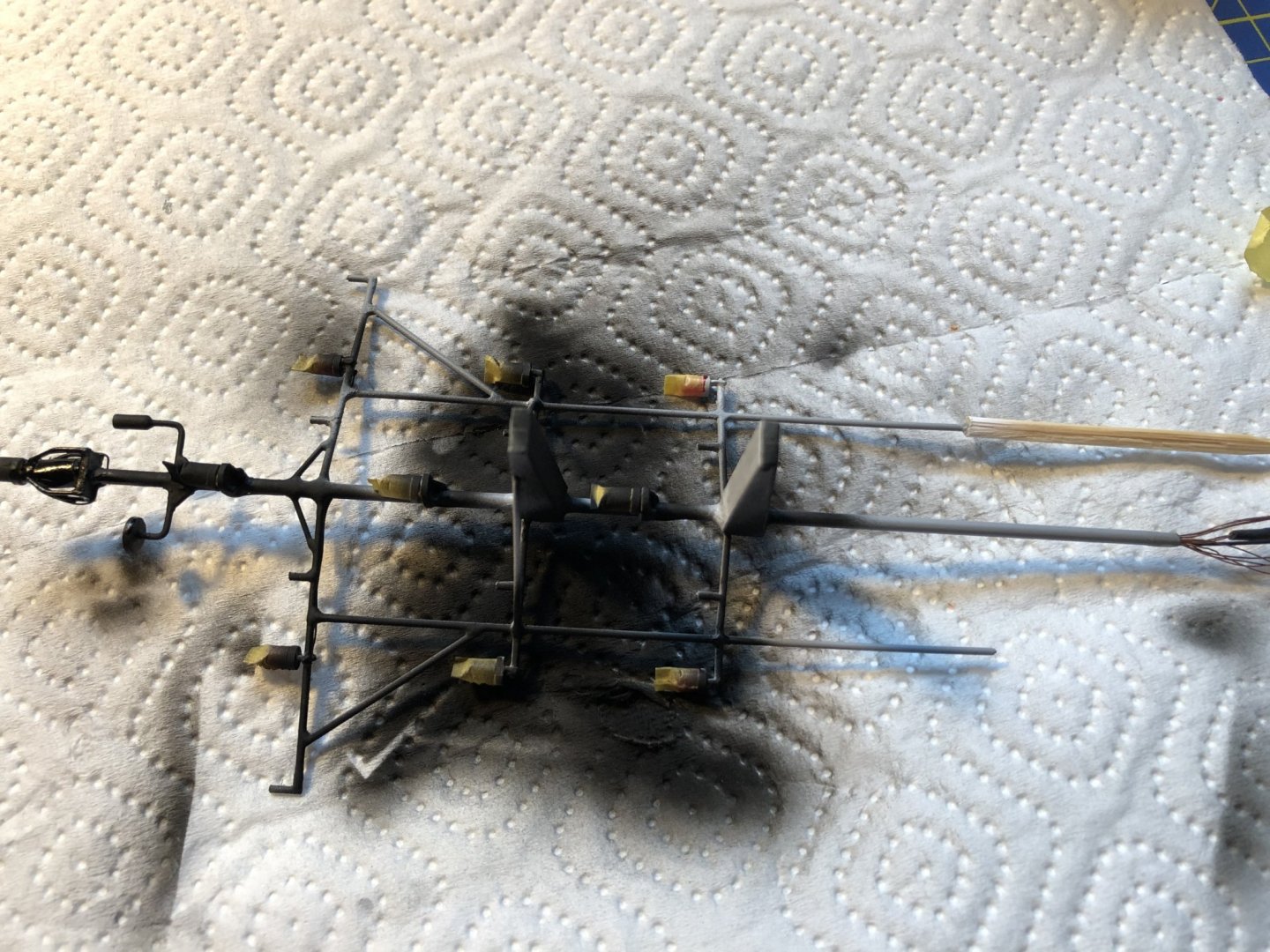
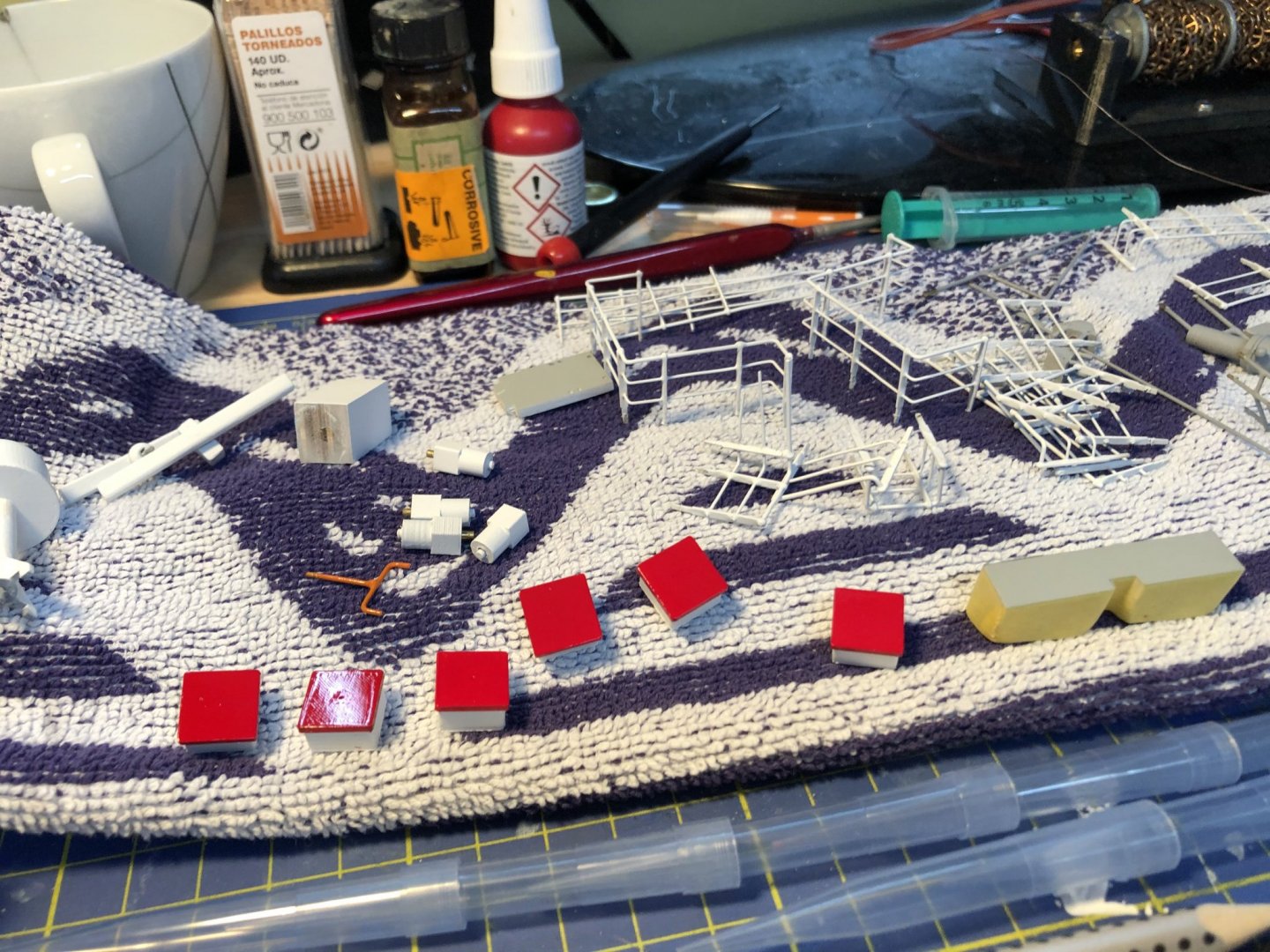
Hello All, Just a short update, I need to start making more pictures... But here are some preview photos of the progress up to now. Gluing of the rope guide rails with epoxy. Yes the shade of the orange is completely diffident... But it will have to do now. And some detail painting, first the main mast being painted in the black, and then some miscellaneous details being primed in white. I must apologize for the composition of the last picture, next time it will be better as I cleaned my table on Sunday. And yes that thing behind is an airplane nosecone waiting to be painted as well. Cheers, George

- 90 replies
-
- 3
-
-
- fairmount alpine
- billing boats
- (and 1 more)
-
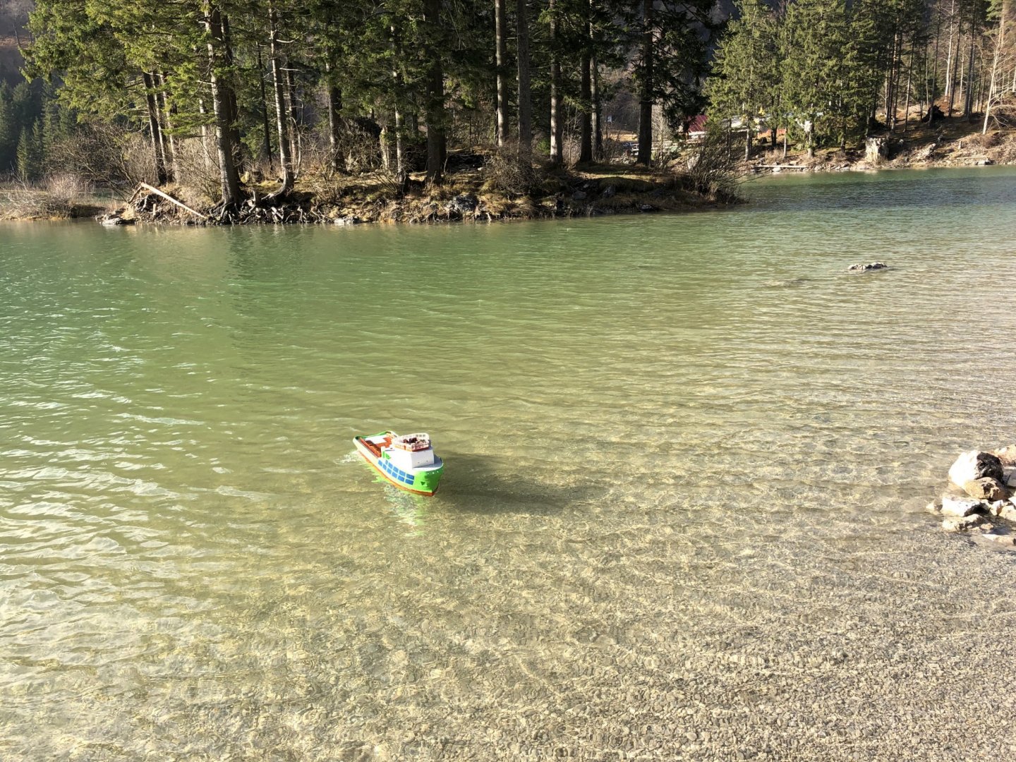
Hello All, @popeye the sailor Thank you, I use these occasional sail as a motivation for the build. @Imagna Yes I can imagine that the Alps here produce similar vistas to those in the Northwest US. Although I only seen that part of the world in pictures... I like that spot on the pictures because usually the water is calm there, and since even in Sommer the water does not reach temps higher than 15ºC there are usually no swimmers. Cheers George
- 90 replies
-
- 1
-
-
- fairmount alpine
- billing boats
- (and 1 more)
-
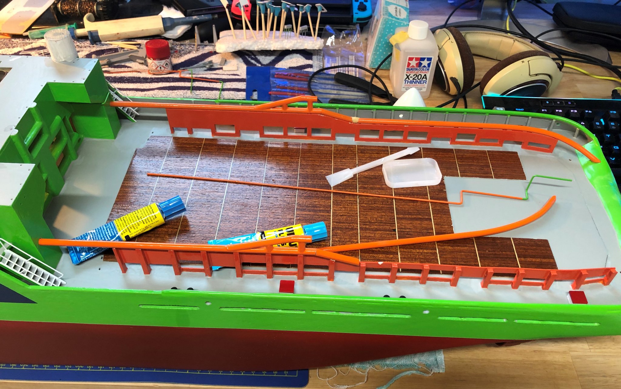
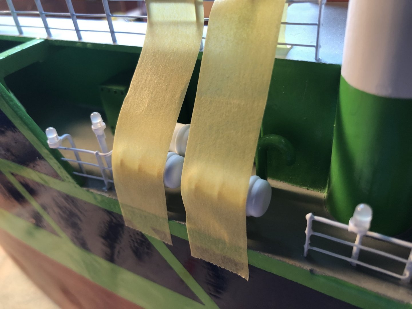
Hello All, As I said here are the pictures of already installed details. The rest of the finished details is waiting for the main towline guards (the pair of orange tubes running on sides) to be painted orange. Cheers George

- 90 replies
-
- 6
-
-
- fairmount alpine
- billing boats
- (and 1 more)
-
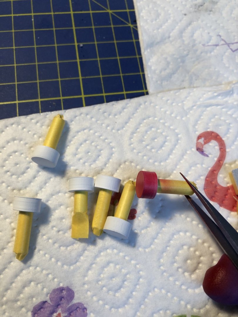
So After a long brake, back to the build. I started by finishing the details for the hull, so the different vents, hatches and so on. For now I will just post a couple of pictures of the details painted, in the following post I will include also when they are mounted on the hull. The hatches still need the locking wheels added. For this I found a PE sheet with different wheel sizes, which I will use for this. I will include a picture in the following post. Cheers George


- 90 replies
-
- 3
-
-
- fairmount alpine
- billing boats
- (and 1 more)
-
@Pete m Hey Pete, Yes I would be glad to share them. Just write me what you want. I will have a look for the files and send them to you in .stl format. Also it is the highest time for me to get back to this build after the winter. BR George
- 90 replies
-
- 1
-
-
- fairmount alpine
- billing boats
- (and 1 more)
-
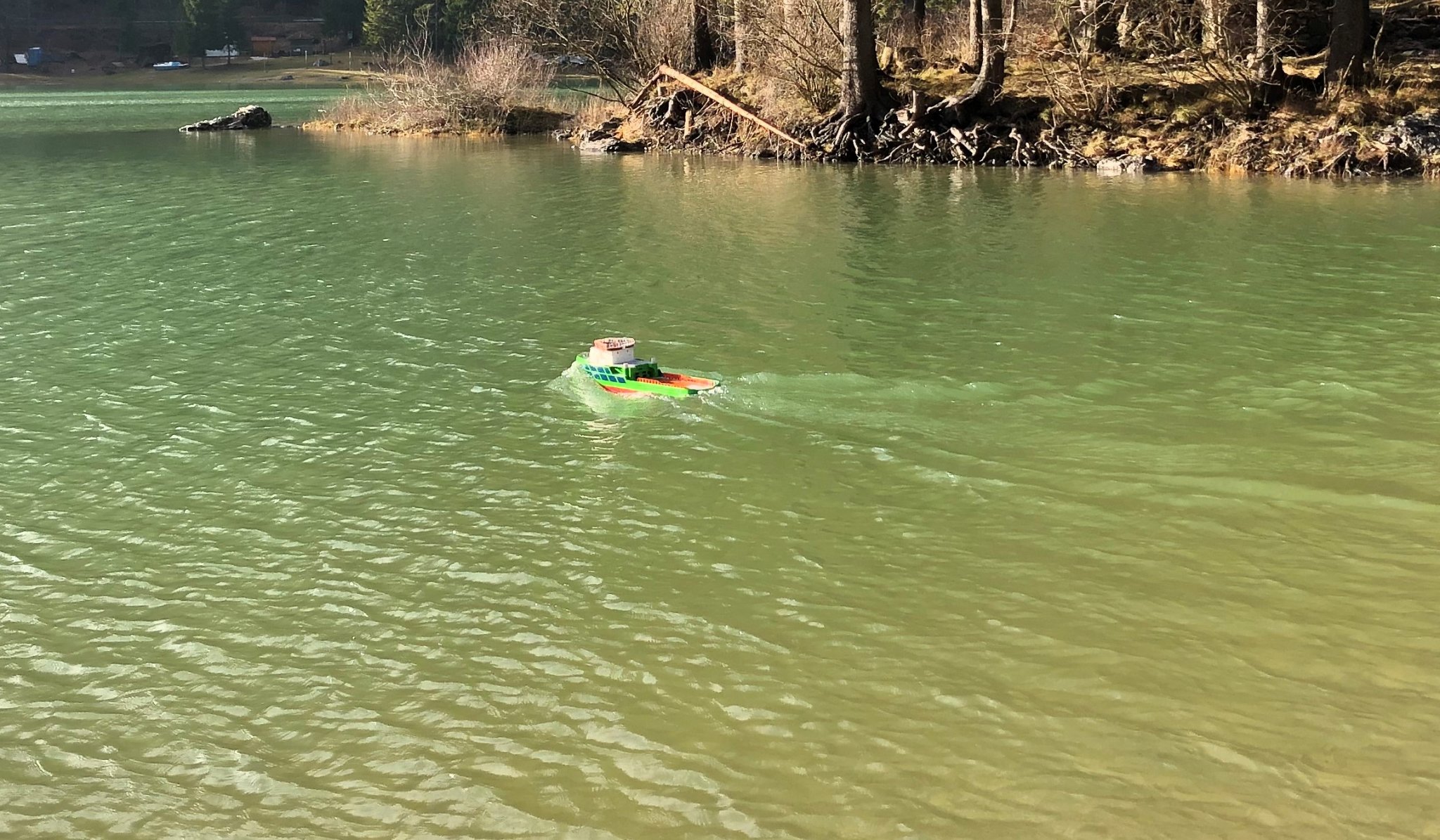
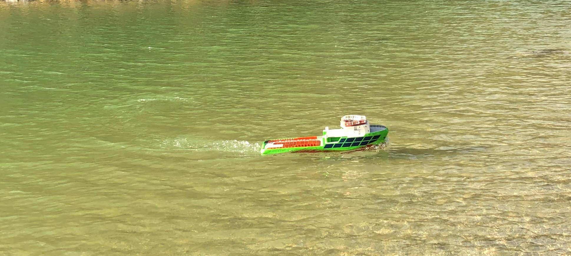
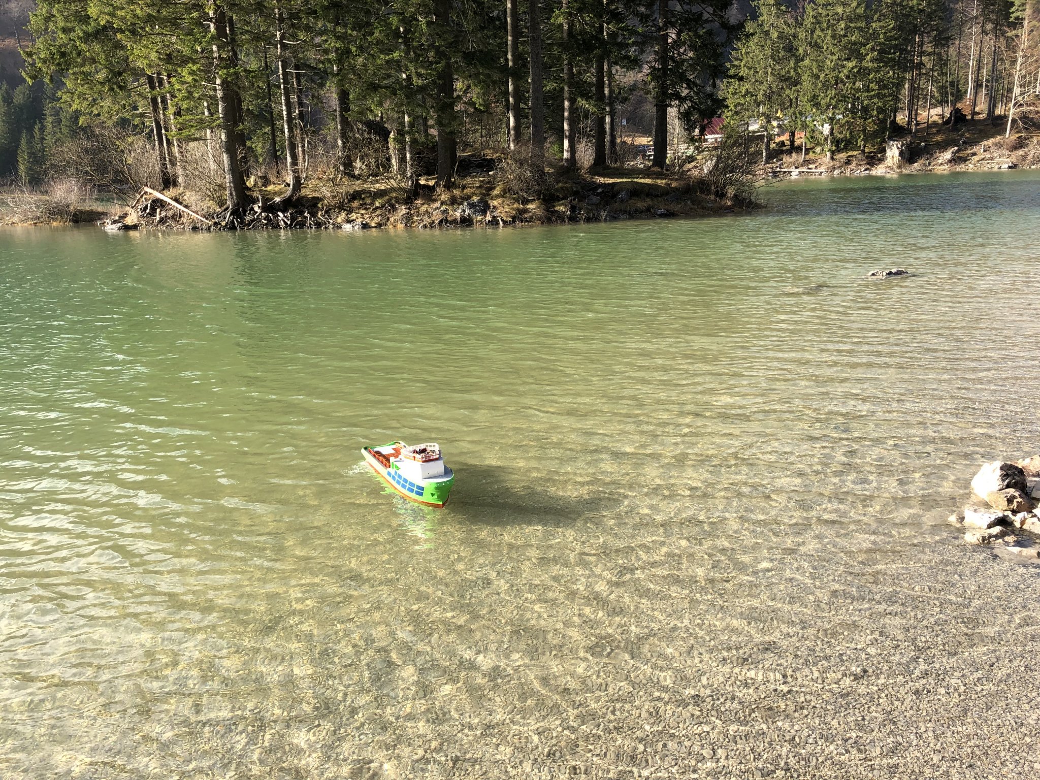
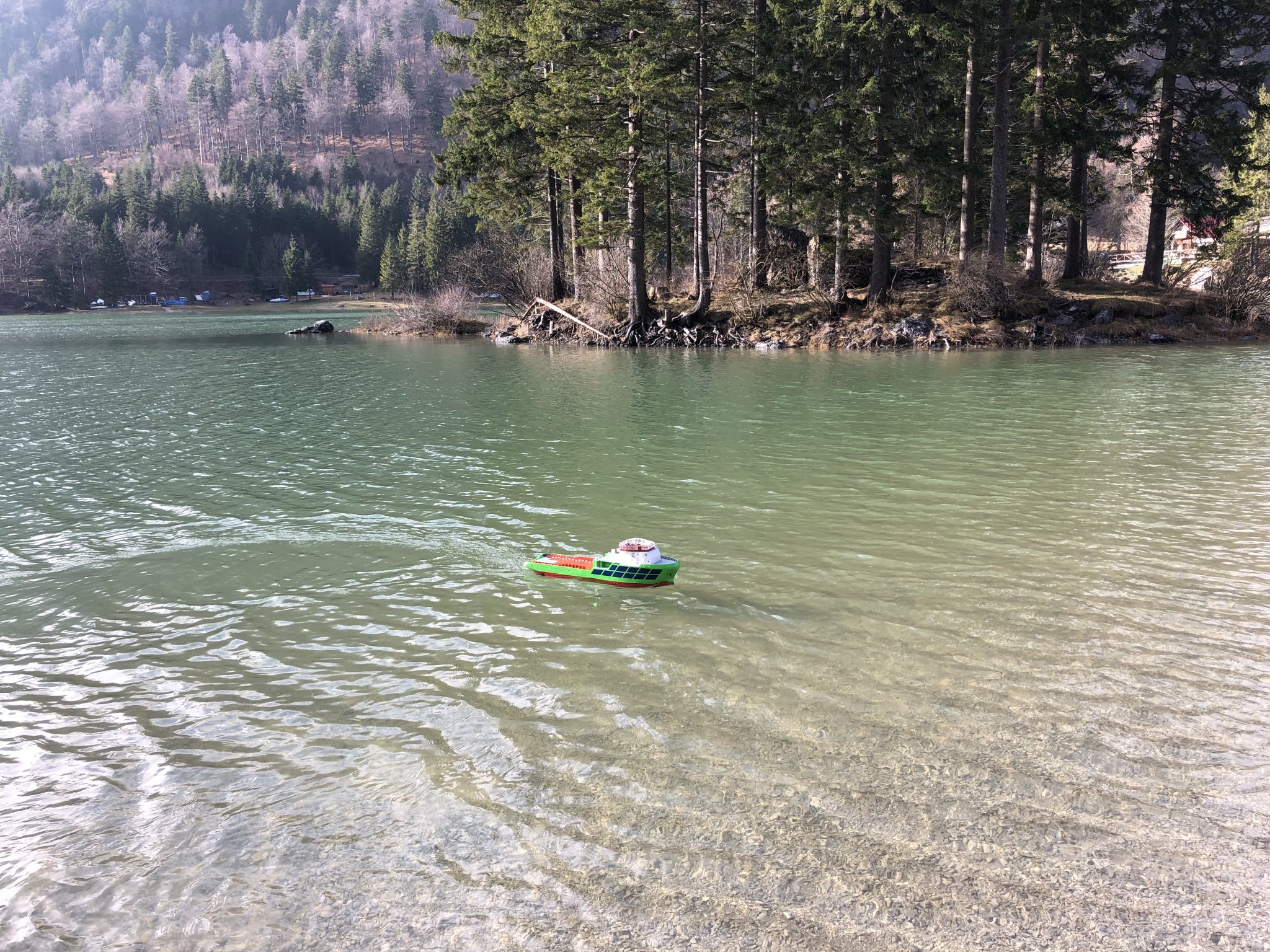
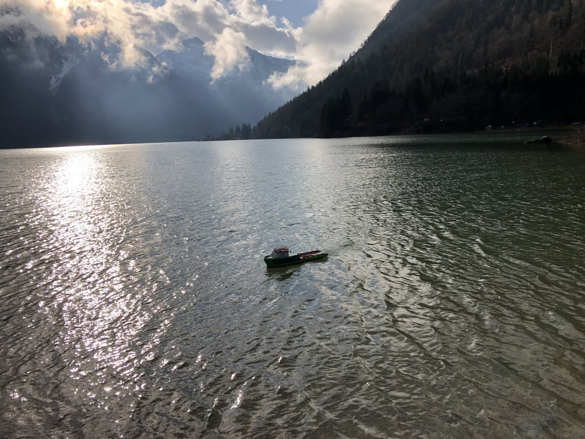
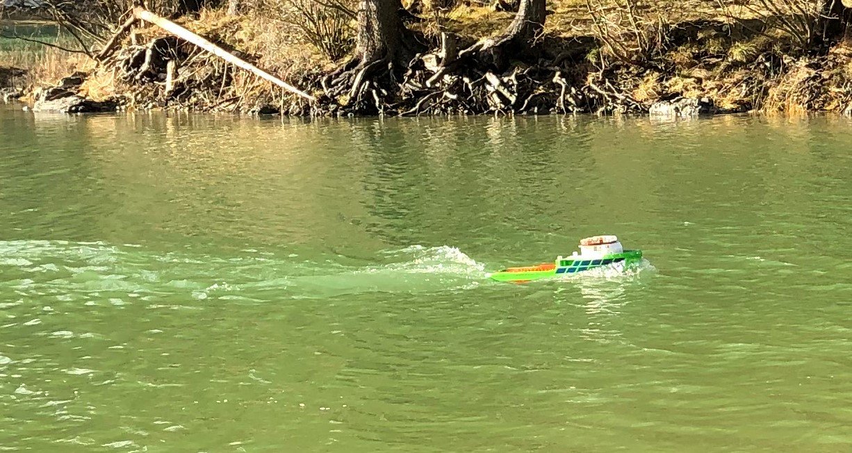
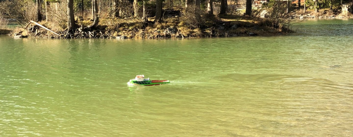
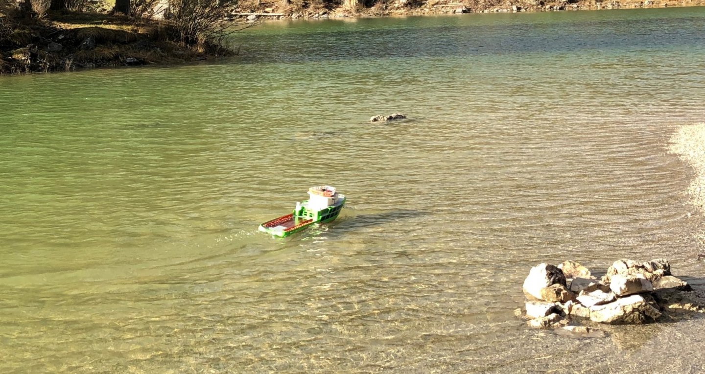
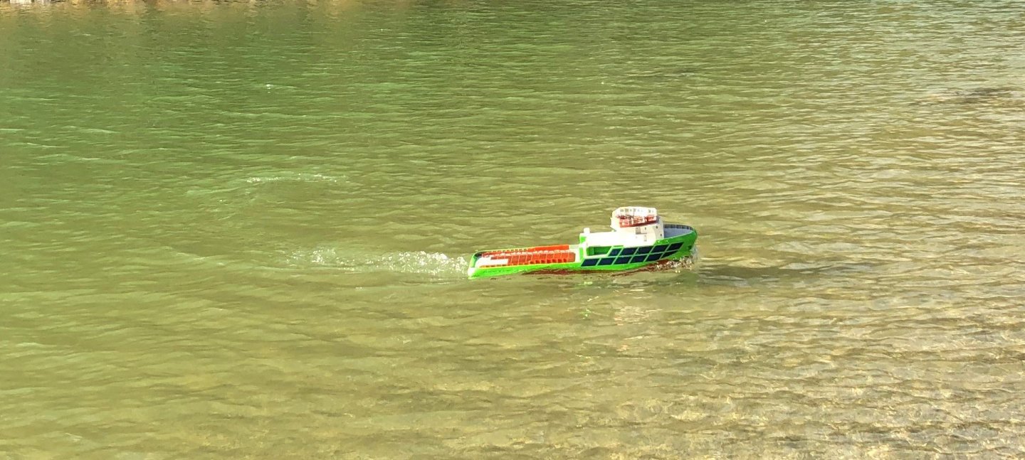
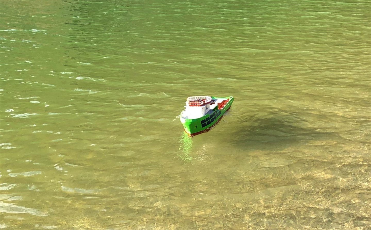
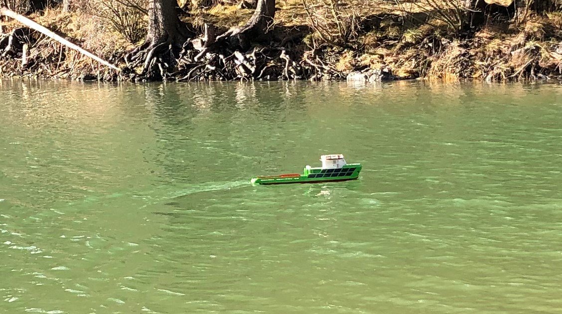
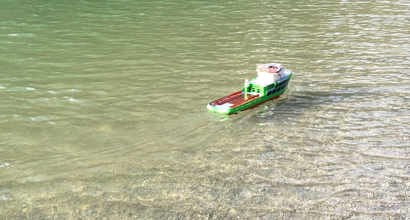
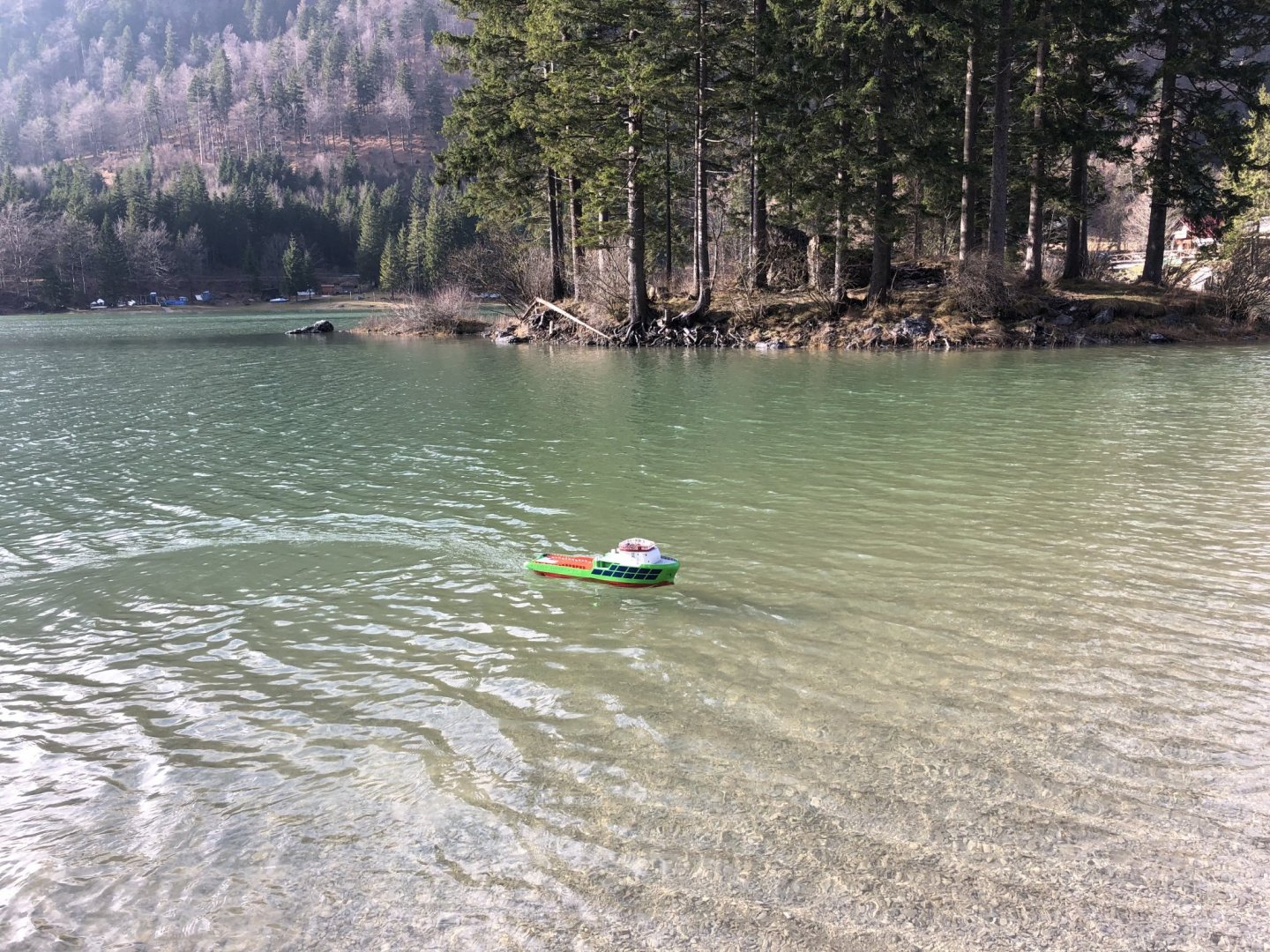
Hello All, I must apologize for my silence in the last couple of weeks, because of the Christmas stuff and work I did't really move forward in the build. The only thing I did still in the November, I sailed the boat here on a lake before it froze. So I will post a couple of pictures from the trials and in the end describe some plans for the future. For the conclusion of the trials, the boat is quite stable even in mild waves. The installed engines and propellers are powerful enough to get the hull info planing mode of sail, which is really unrealistic, but I needed to test the throttle response. I also wanted to check the water tightness in real life, but since I managed to flood the stern deck from the not so slow decrease in throttle, which resulted in a wave running over the stern and breaking on the opened bulkhead where the tow lines are exiting the hull (no idea if it has some special name..). This resulted in almost 0.5L of water in the hull, so instead of hull water tightness I tested the electronics resistance to flooding, also important test, but completely unnecessary one. In regards to the latest displacement, it is 11kg and the hull still sits quite high above the water, it is still almost 10mm to the painted waterline. In the end I was quite satisfied with the overal behavior of the ship, I learned that it will be necessary to add a seal on aforementioned bulkhead, to minimize the chance of flooding the batteries again, as well as to protect the planned light control unit which is meant to be situated right there. Regarding future post, I am not sure if I will post until after the holidays. So I ask for prolonged patience with following updates. Cheers George


- 90 replies
-
- 4
-
-
- fairmount alpine
- billing boats
- (and 1 more)
-
Hello All, A small update, on the buil, today w/o pictures, I apologie for that. Yesterday I did an electrical testing the the systems, I found a slight problem with the main engines. First they start to vibrate at relatively low RPM, this will require some bracing of the shafts near the engine mounts. this was an expected, but still unwanted event, a piece of balsa wood and glue per shaft will do the trick. And the second problem, which is quite interesting is that during the initial testing the two engines didn't start to run on the same throttle position, however this problem disappeared after more testing. I suspect a combination of the ECS settings and different "resistance to turn" of the two shafts, I will try to improve this by programming the ESCs. And last problem that was discovered was, that I probably siliconed the stern thruster too well so to speak, meaning I blocked the paddle from turning. For this was an easy fix, since the silicone doesn't bond strongly to either piece the disassembly was easy, I returned to the supplied O-ring and generous amount of grease, the same one as I use in the main shafts. Today I hope to do a new bath tub test of the water tightness and if the weather allows on Saturday go to Italy to do a sail on one of the Alpine lake here. @Seamanpeter I am also planning to put the DIY LED lighting control unit on top of the battery-pack, however first I have to build it, that will be a challenge. Cheers George
- 90 replies
-
- 2
-
-
- fairmount alpine
- billing boats
- (and 1 more)
-
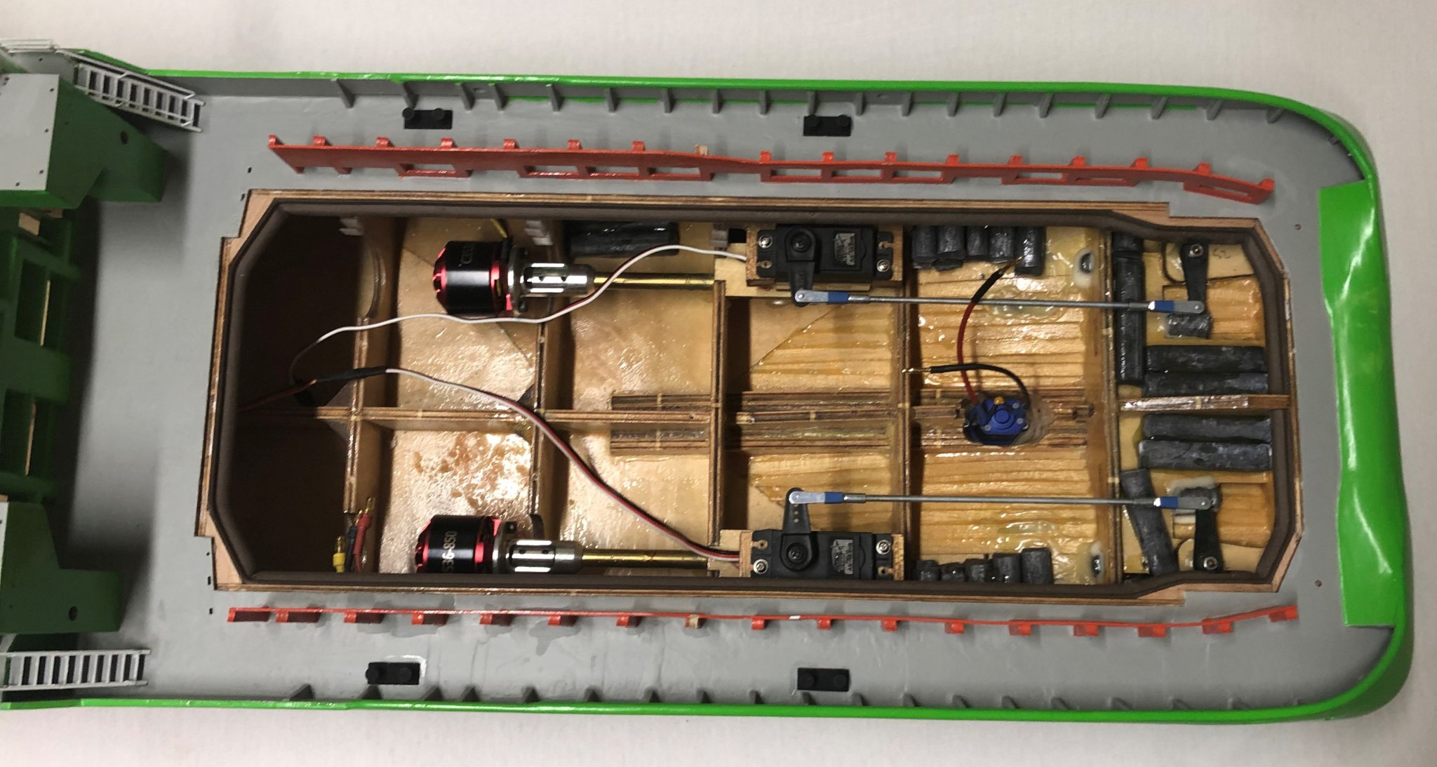
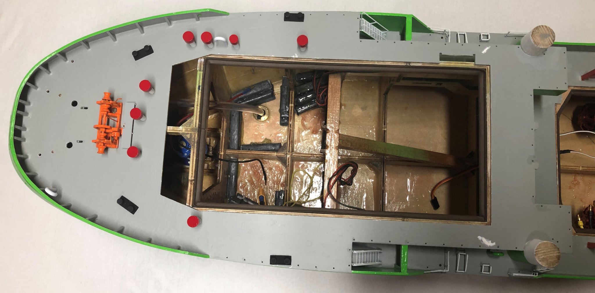
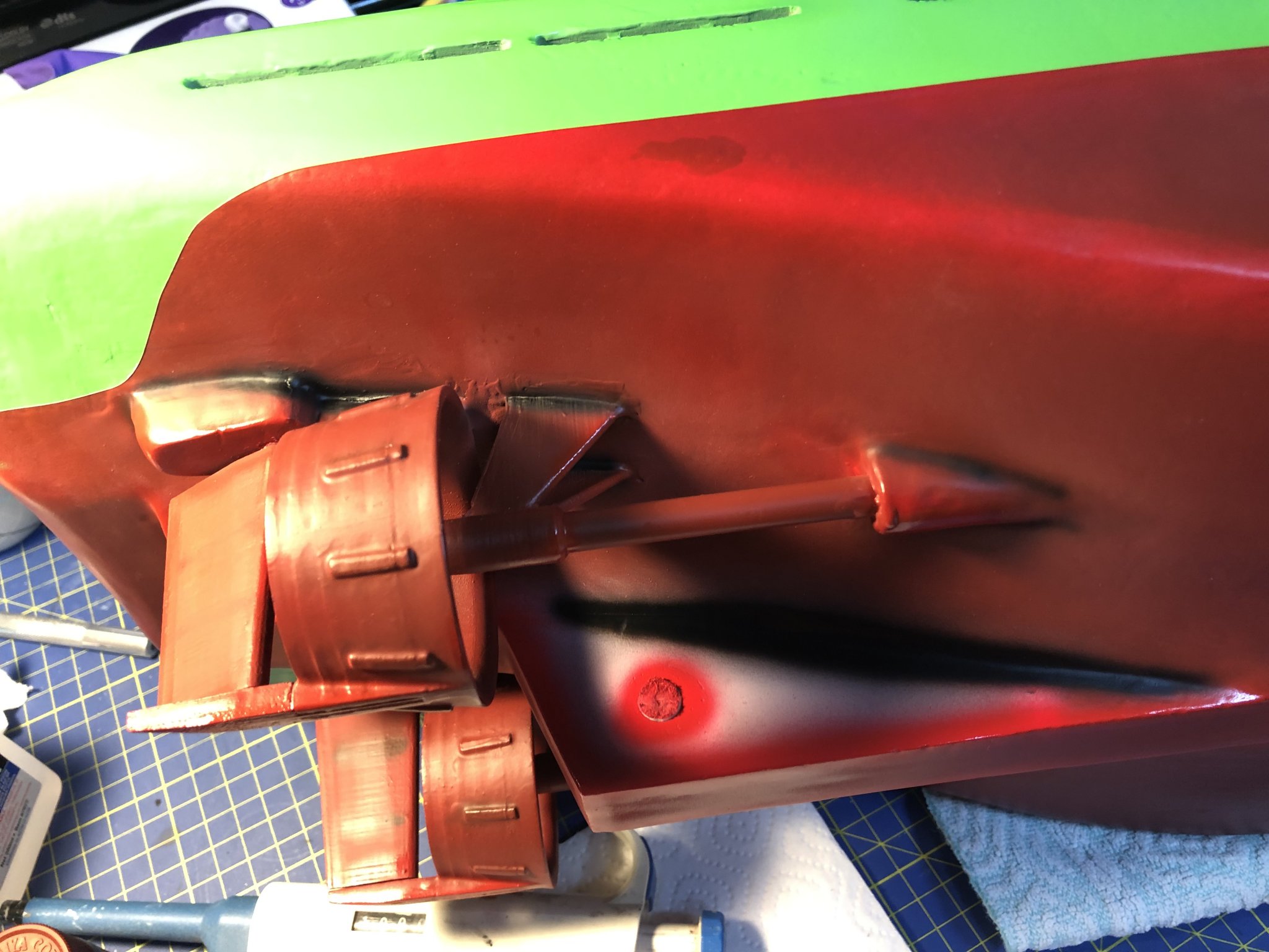
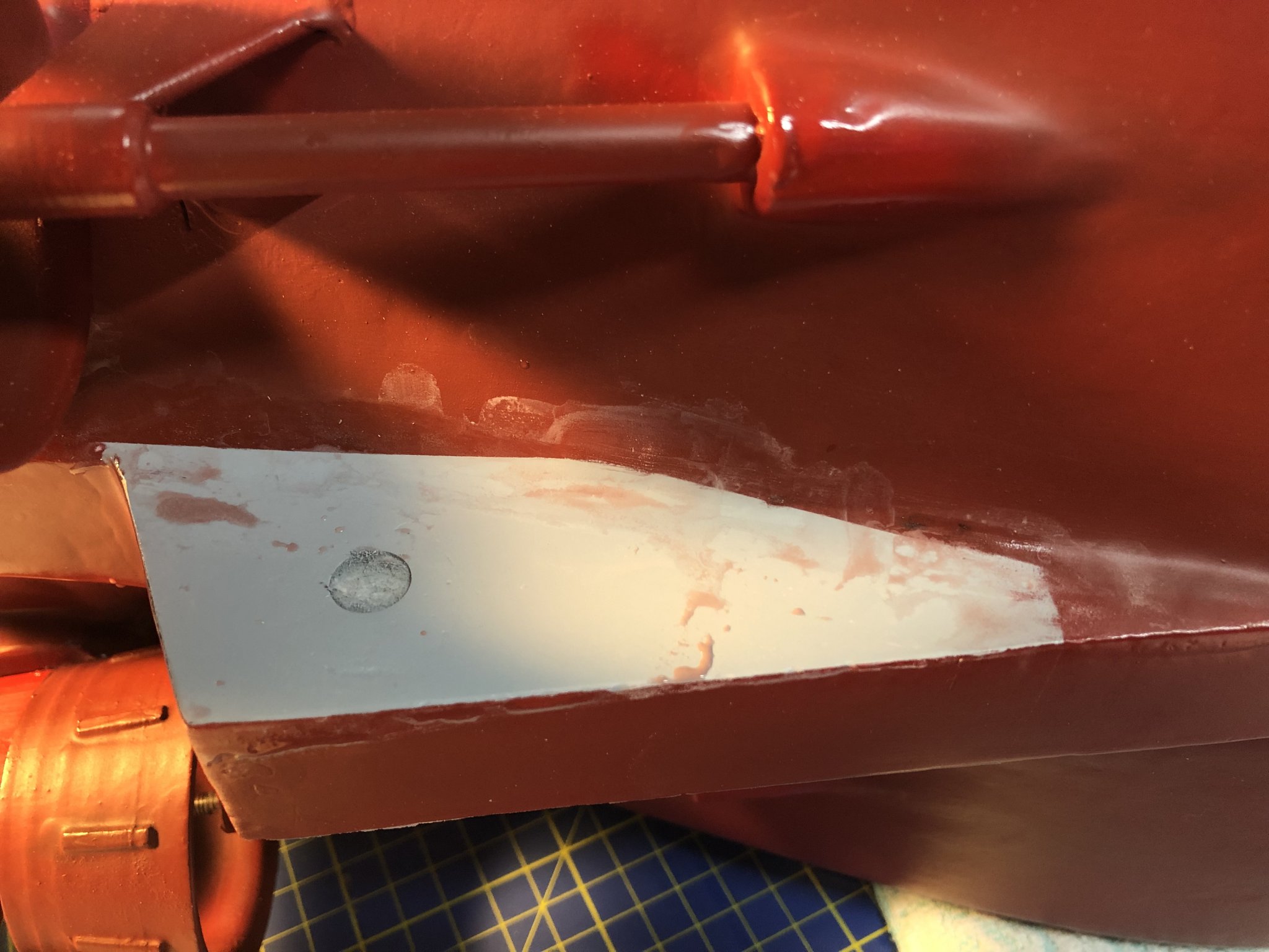
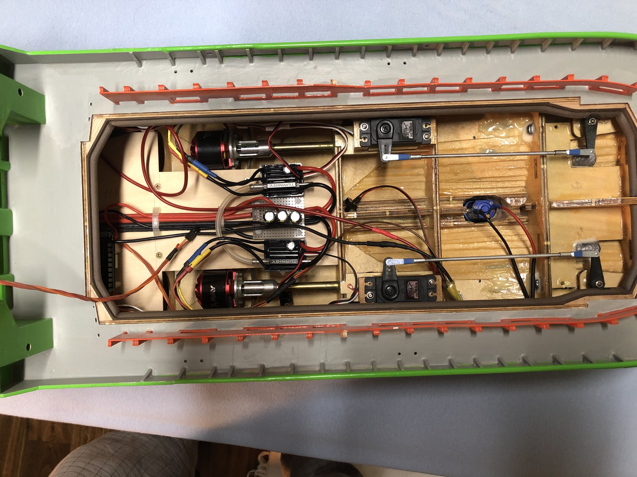
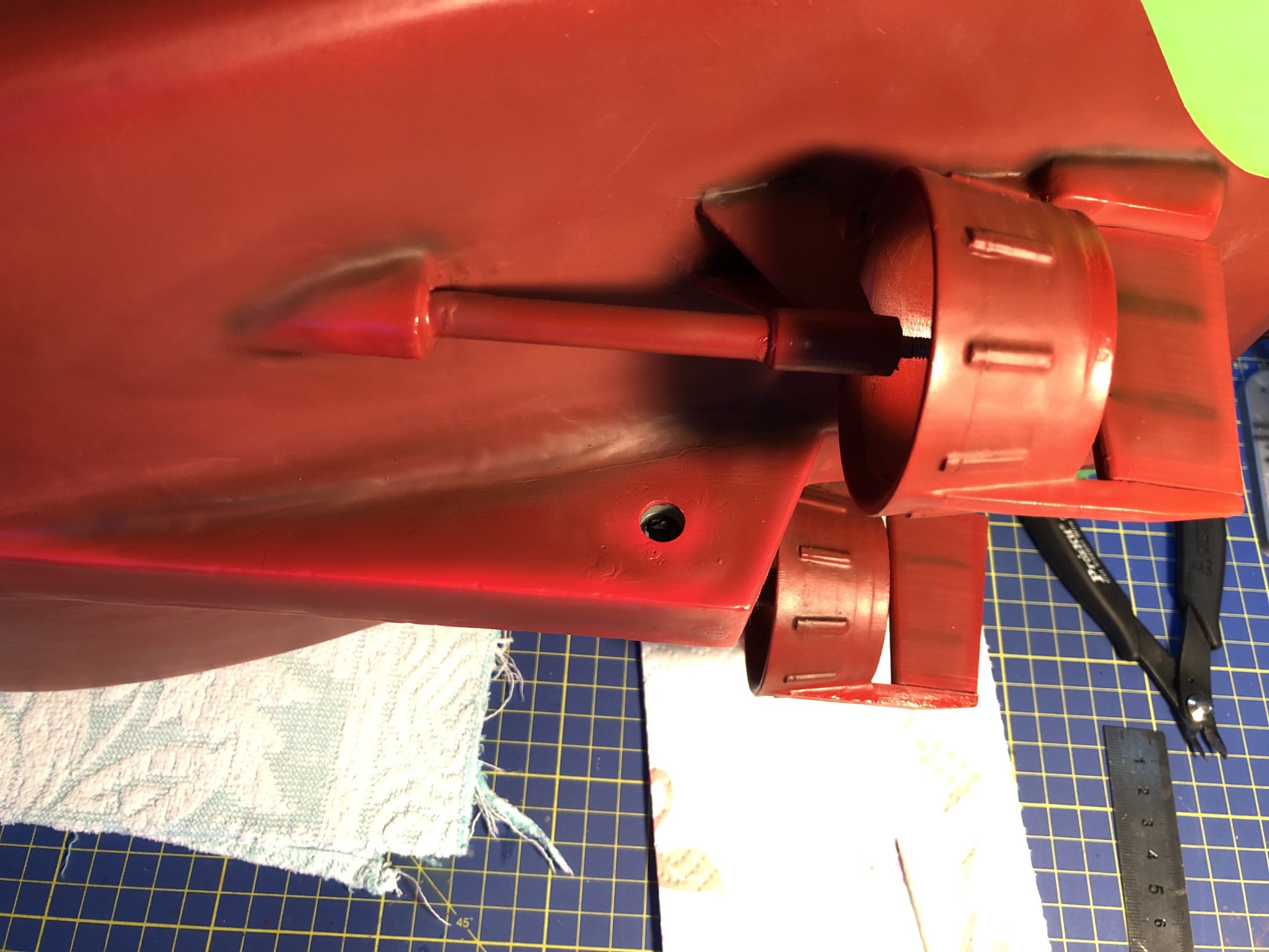
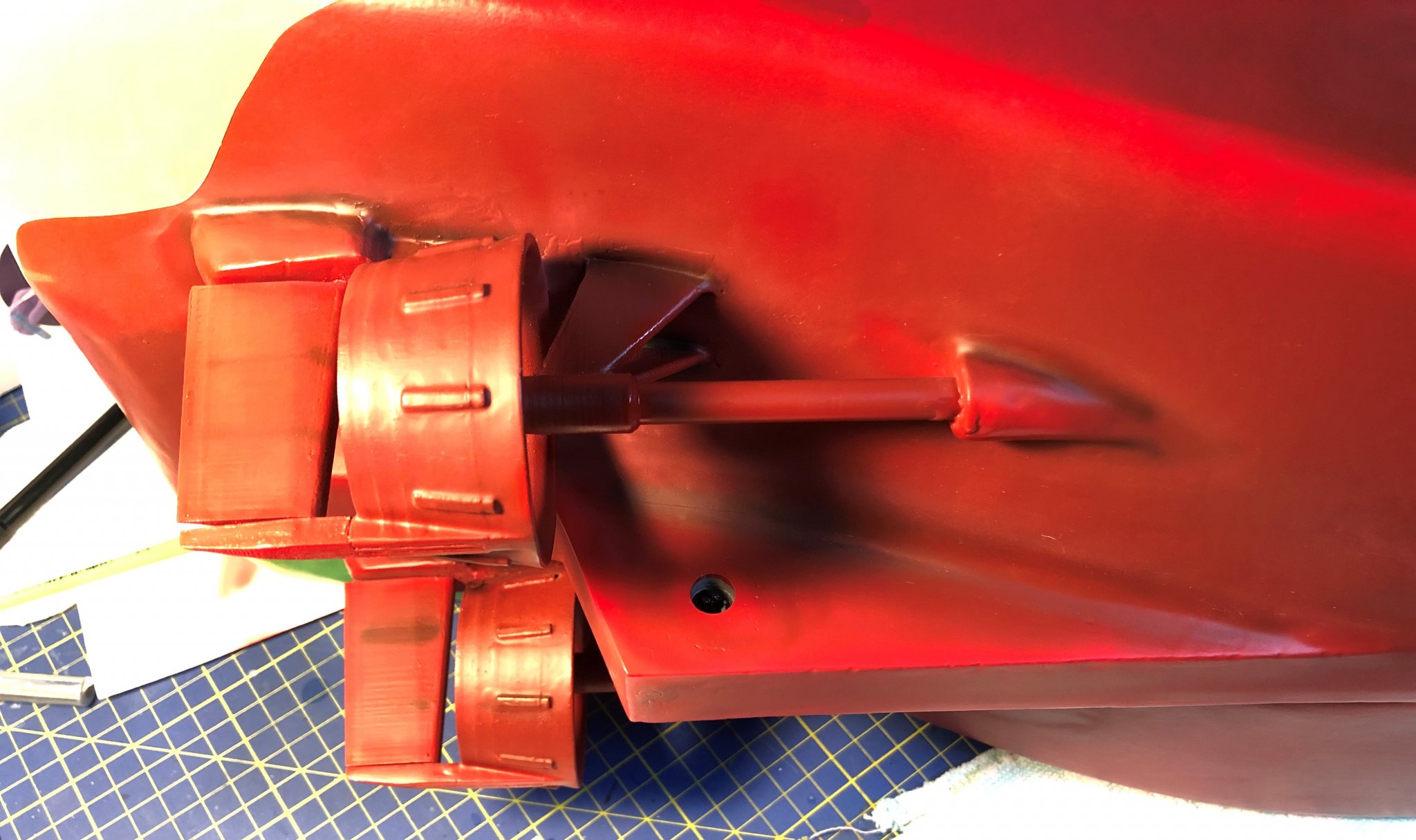
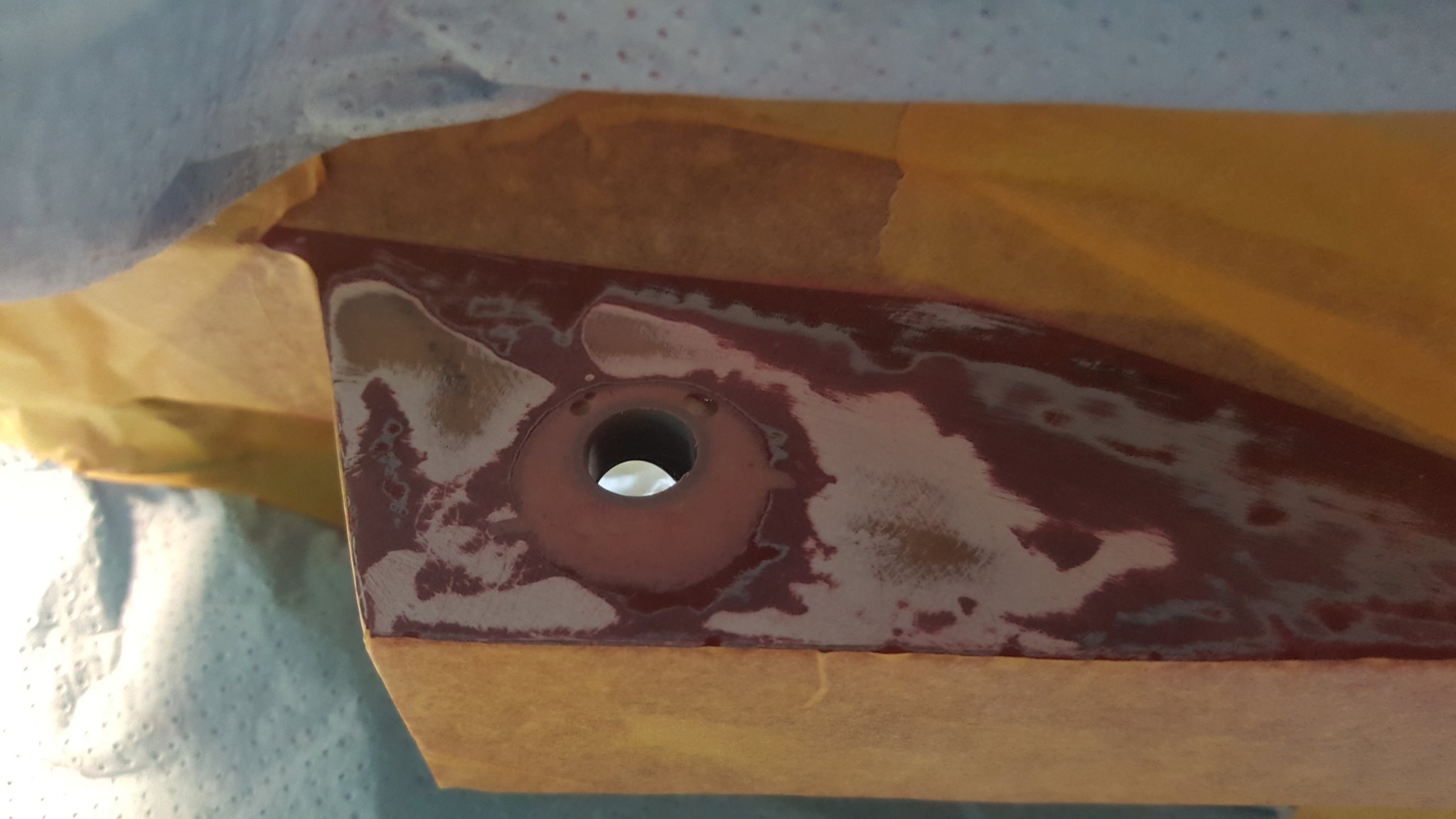
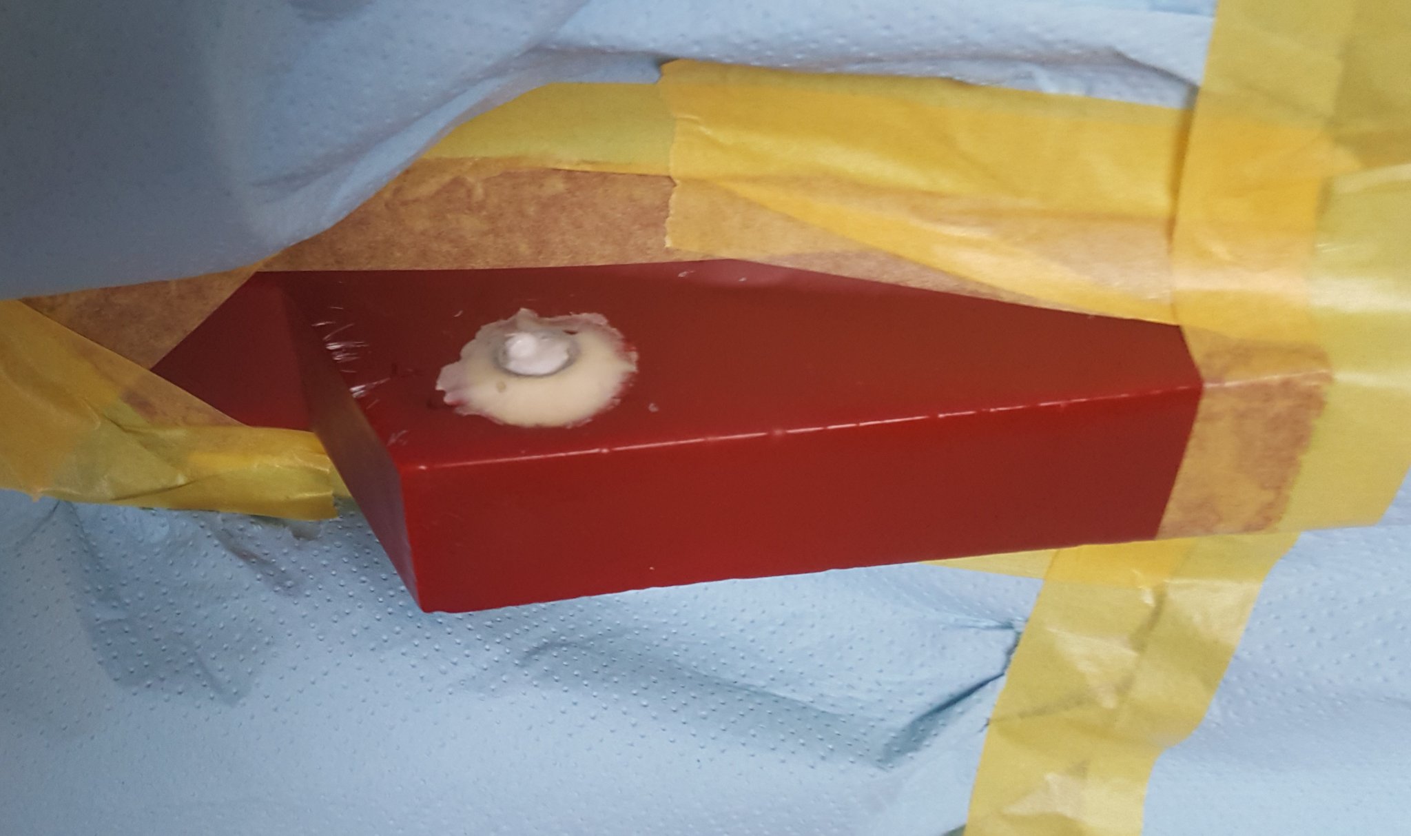
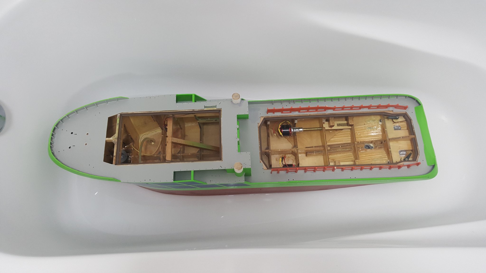
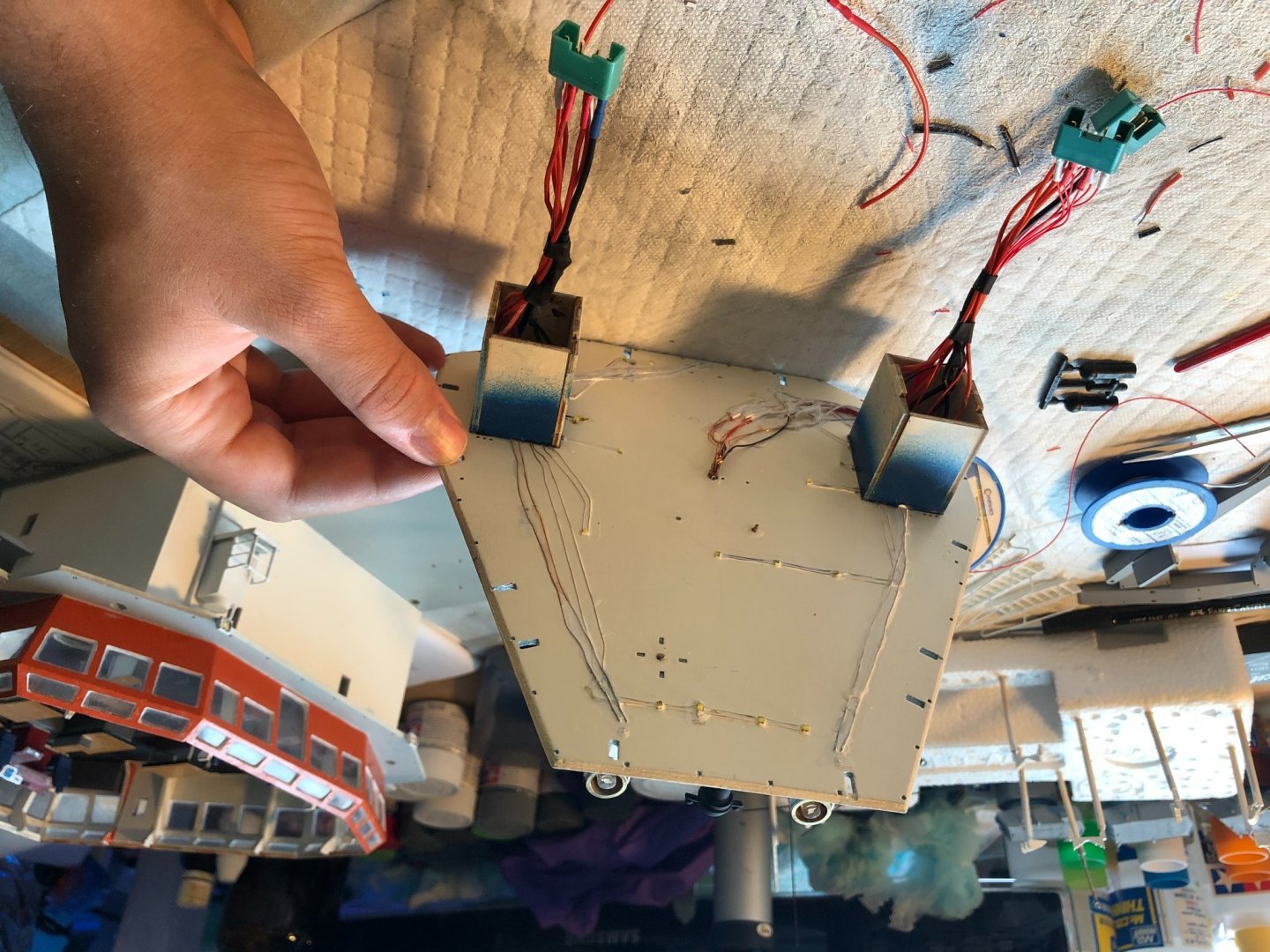
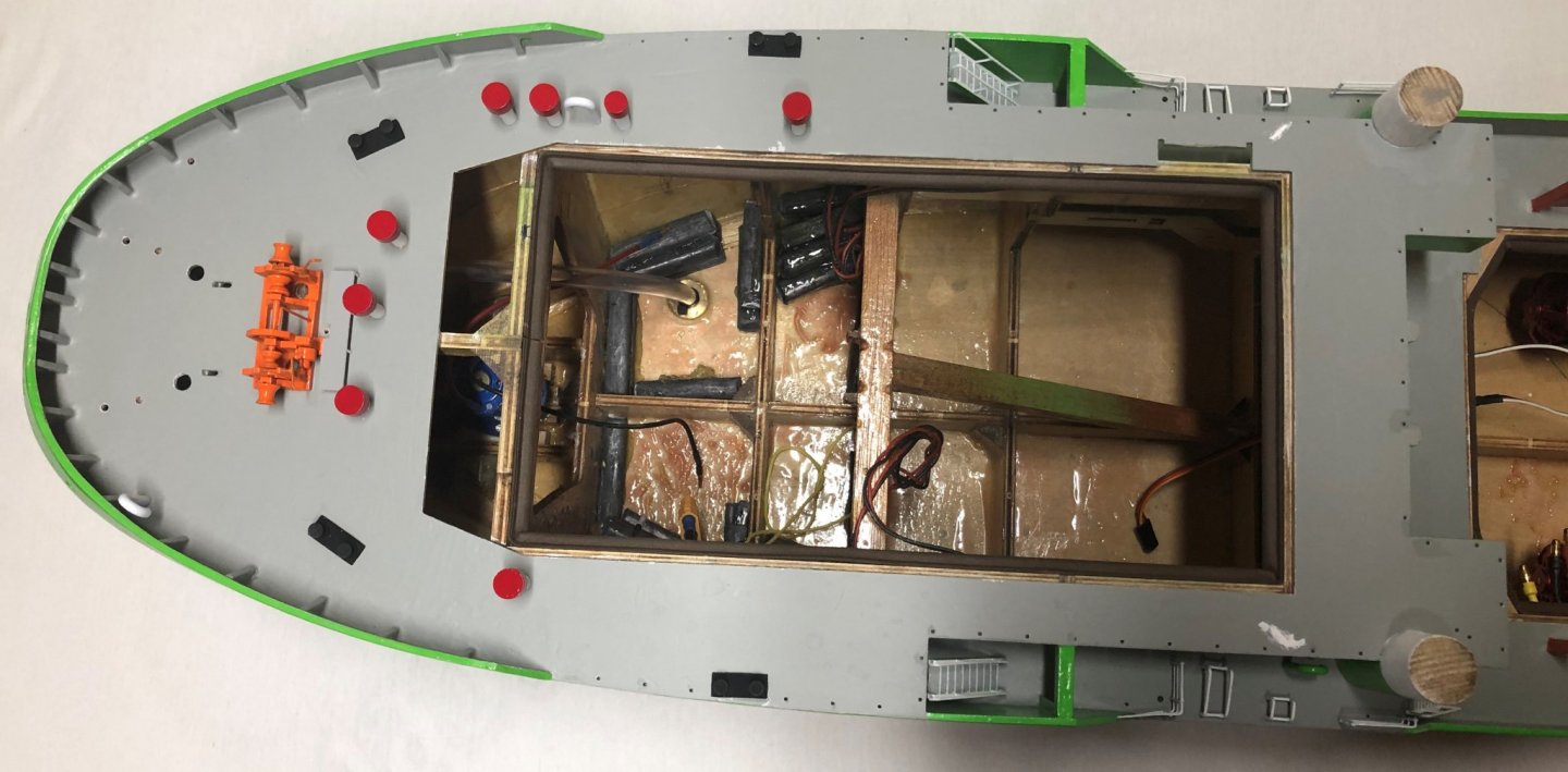
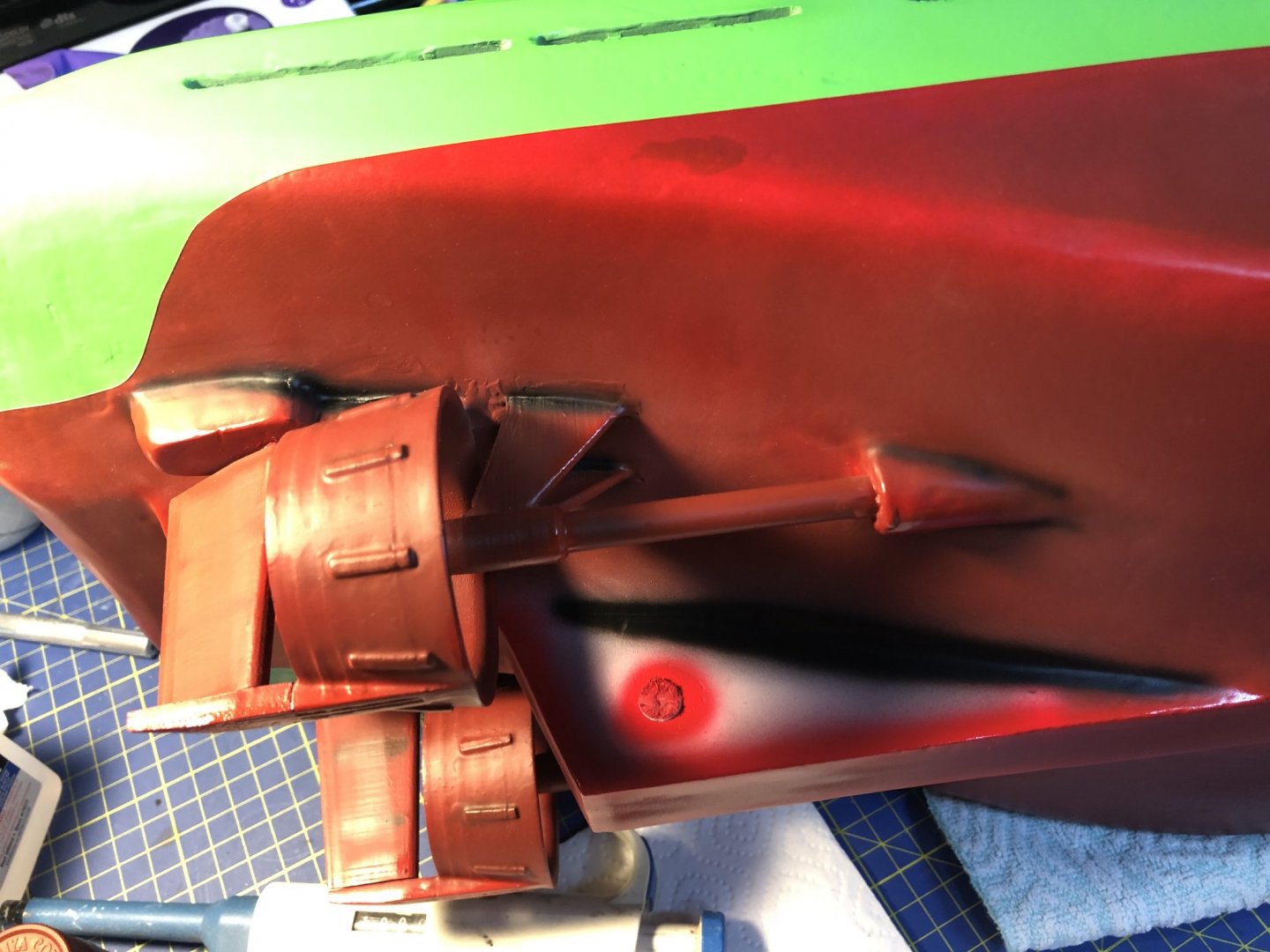
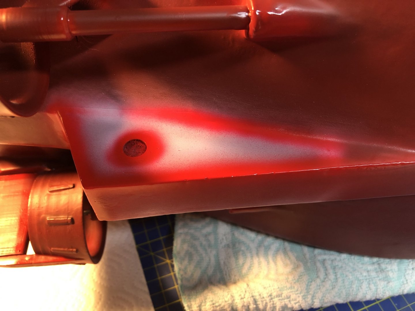
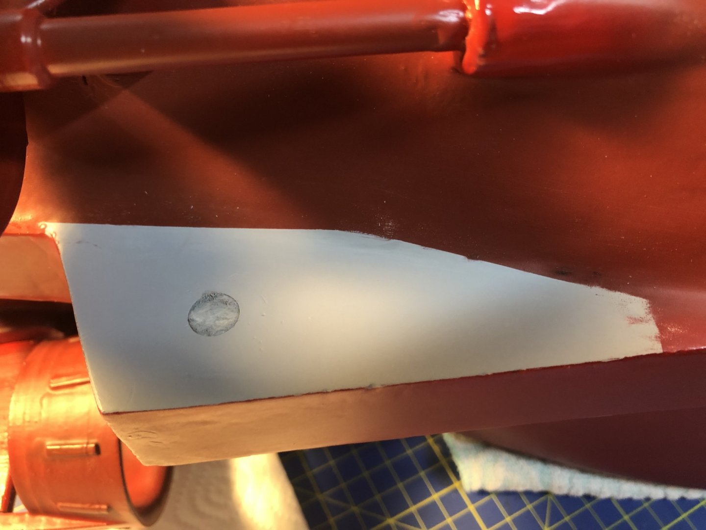
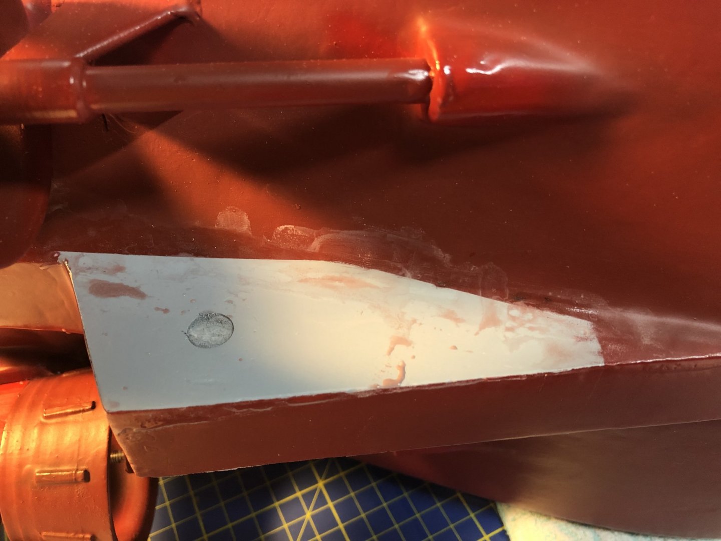
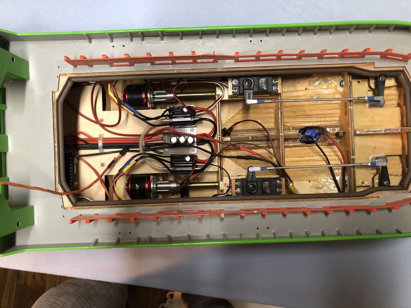
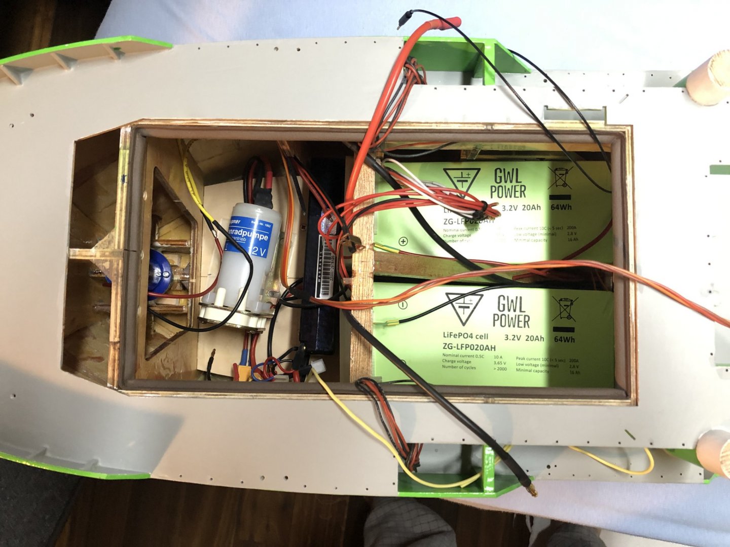
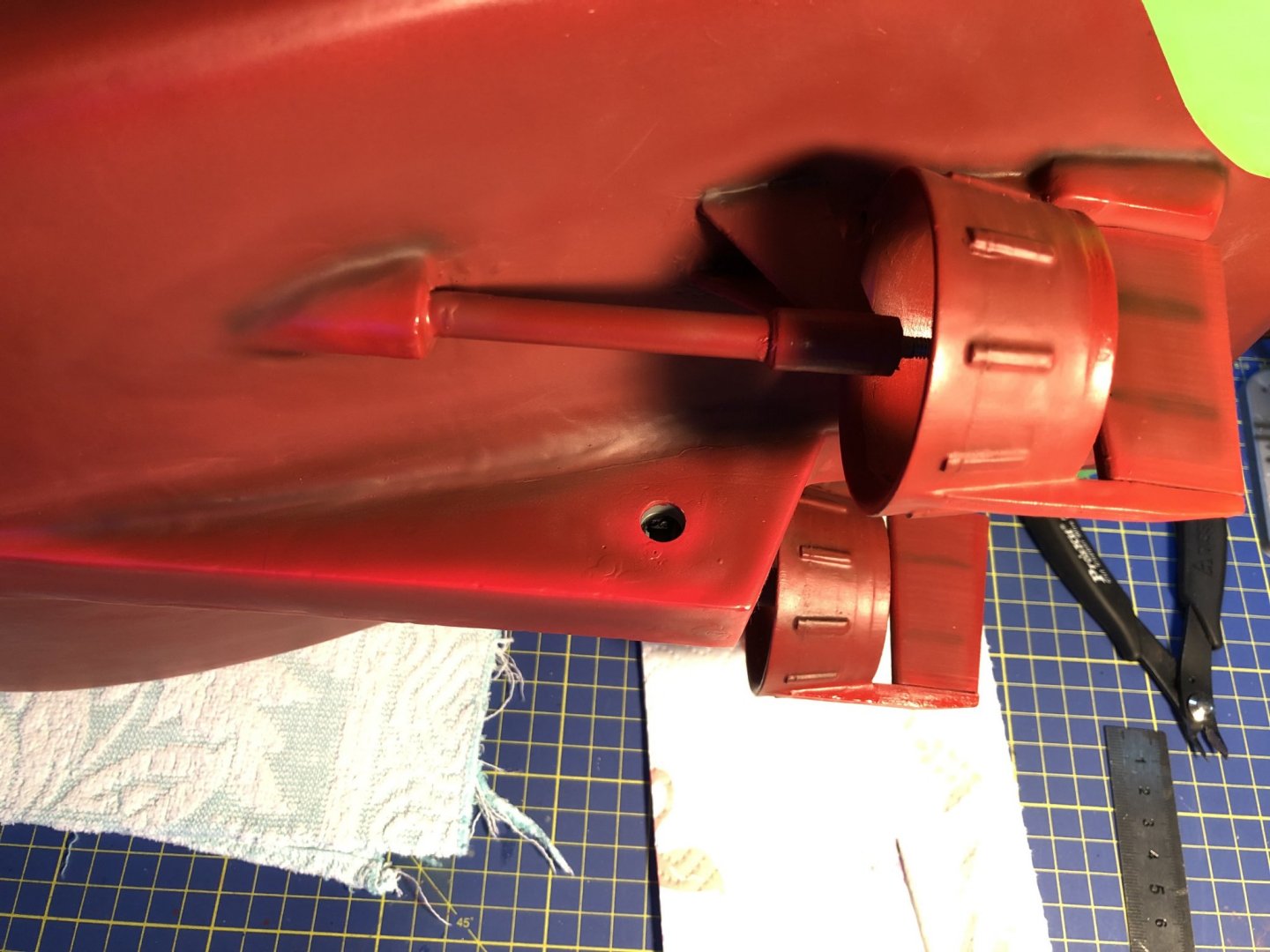
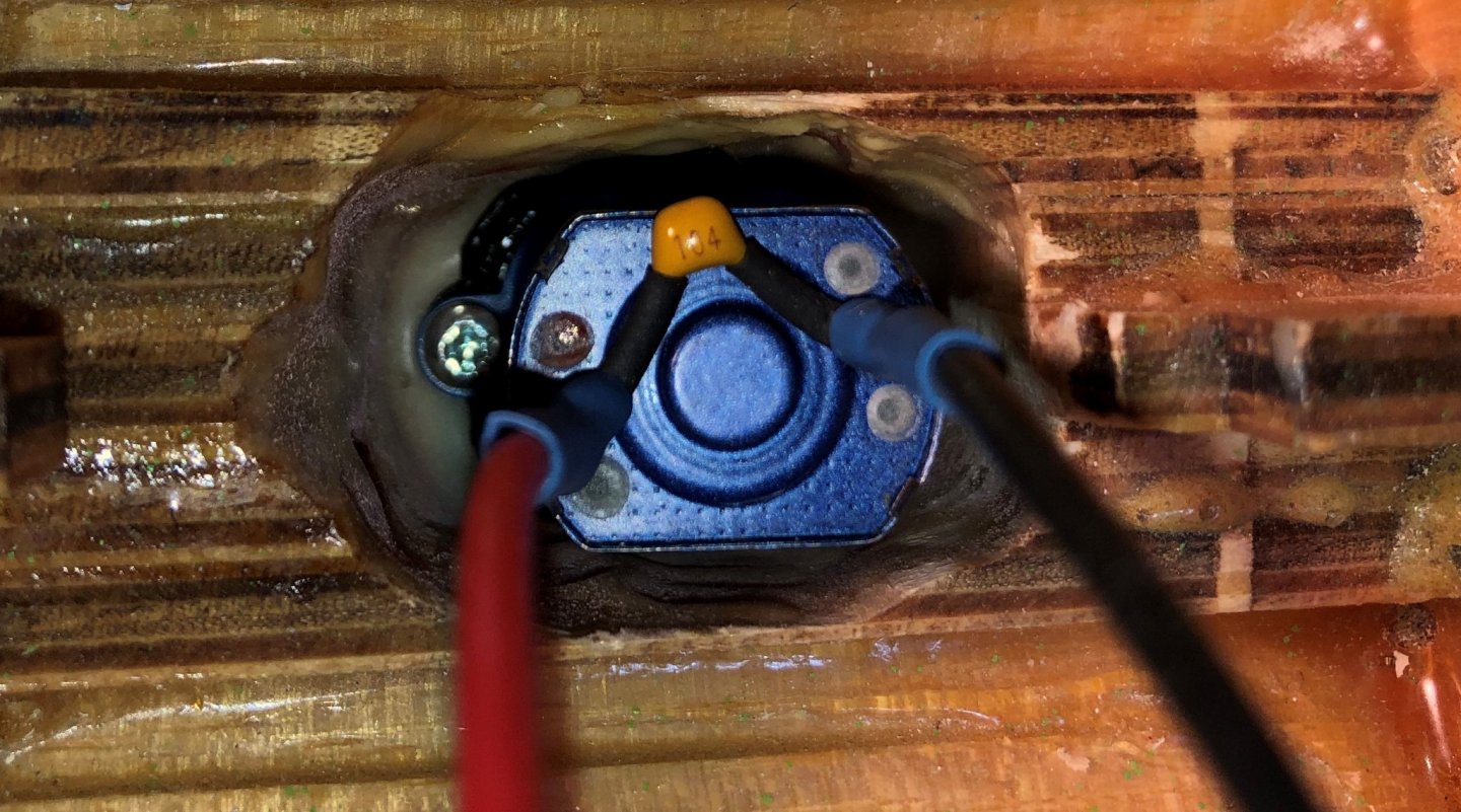
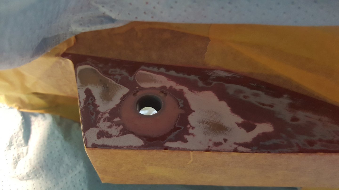
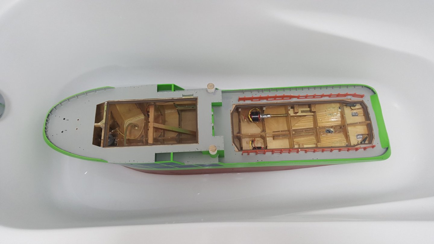
Hello All, A small update today. I finished the repairs on the deadwood? (I think this is the correct term for this part of the stern. I used again Tamiya primer, and afterwards some accenting with red and black and finally the Dull red as the antifouling paint. First I wet sanded the transition between the new primer area and the already painted area. Accenting using the red and black paint. Final overlay of the dull red paint. I find this colour to be quite tricky to apply as when it is fresh airbrushed it is almost translucent. As it dries it becomes more and more opaque. So it is quite difficult to get the layer thickness correctly on complicated shapes with lots of shadows as is the case with this deadwood?. I mounted the stern thuster motor using generous amount of high temp silicone, as I experienced a leak from the original O-ring. This should solve that problem and keep some level of serviceability to the thruster. And finally for today post pictures of the interior of the hull with installed RC equipment. With this equipment the weight is at 6.4kg including the two battery packs needed for the 12V and 7.2V parts. Cheers George

- 90 replies
-
- 3
-
-
- fairmount alpine
- billing boats
- (and 1 more)
-
Hello Peter, For now I suspended further works, as when I get from work it is already dark outside, so not the optimal weather for painting with rattle cans, I will do some progress on the weekend. I have yet to make all the details on the superstructure, I went on the details the same way as with plastic models, first I paint and prepare the details off the model, and I add them as I go with the complete build. Which works with plastic models, with this, I am not sure, but we will see.... Regarding the kim keel, I originally wanted to build it in, but later I forgot, or rather decided not to build it in, as I didn't to make the build more complicated then necessary at that time... I will therefore have to be smart as to how I distribute the ballast, as physics should be able to compensate for the missing keel a bit. And it should be possible to calculate in a first approximation. Cheers Geroge
- 90 replies
-
- 2
-
-
- fairmount alpine
- billing boats
- (and 1 more)
-
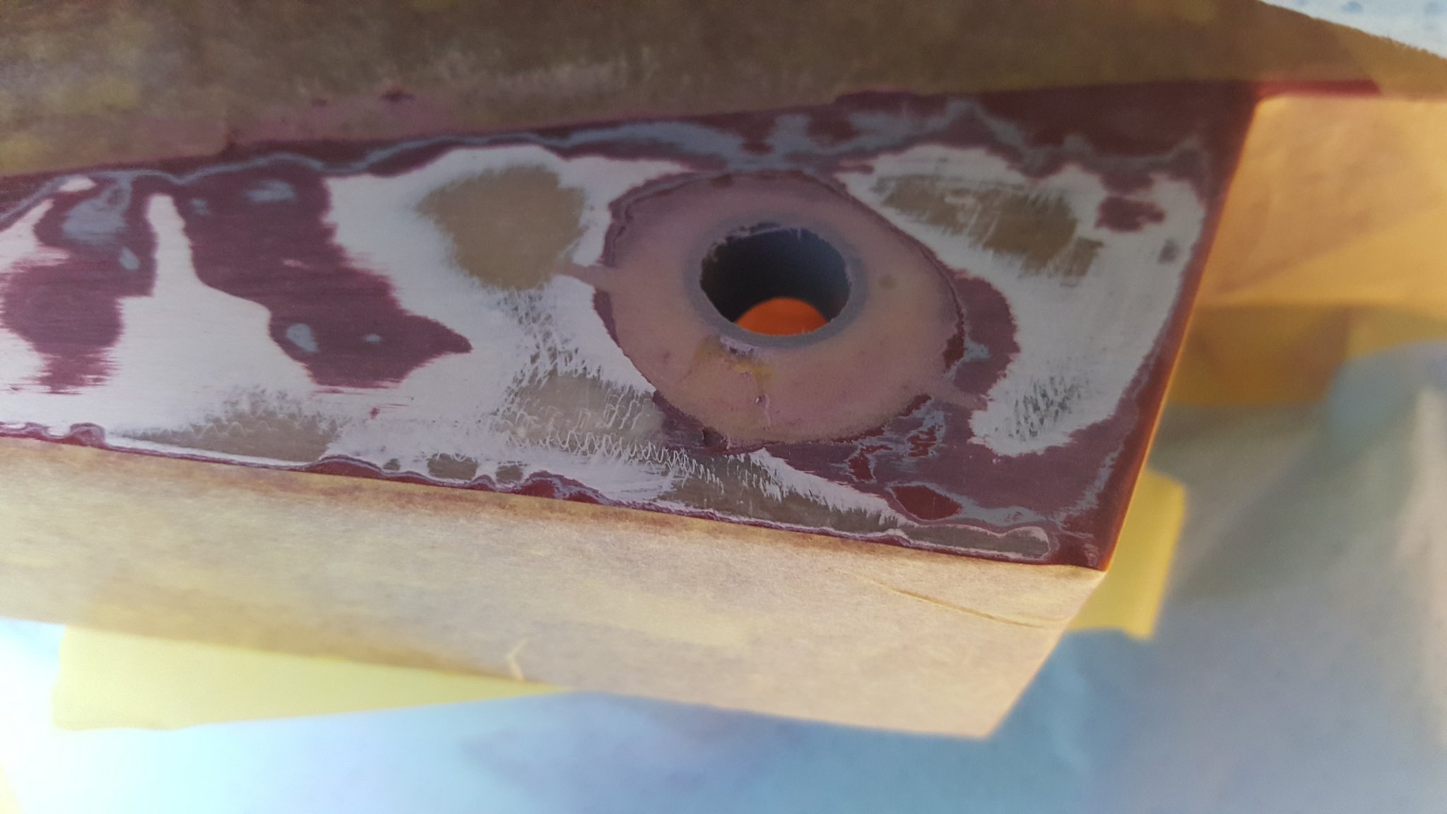
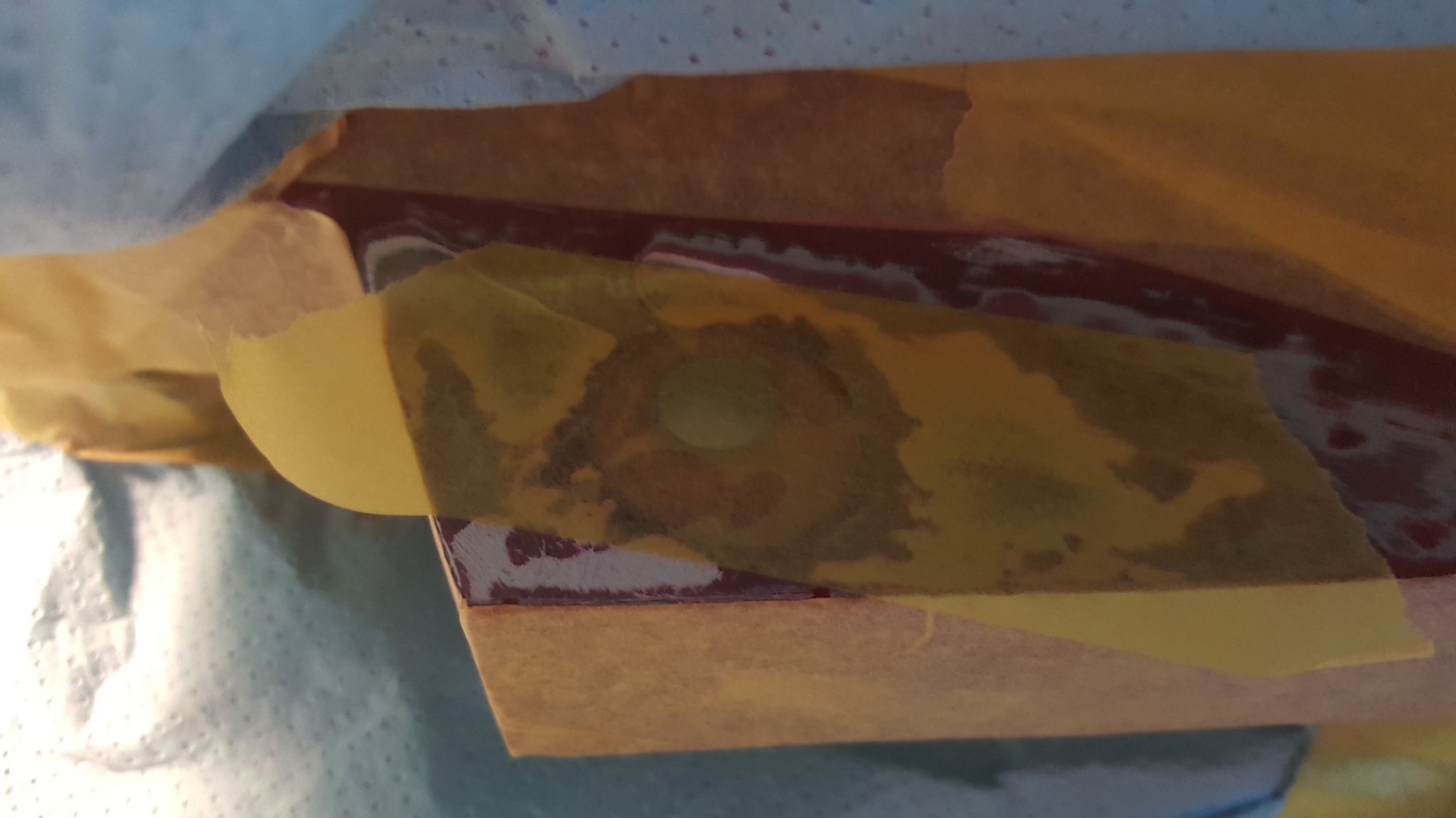
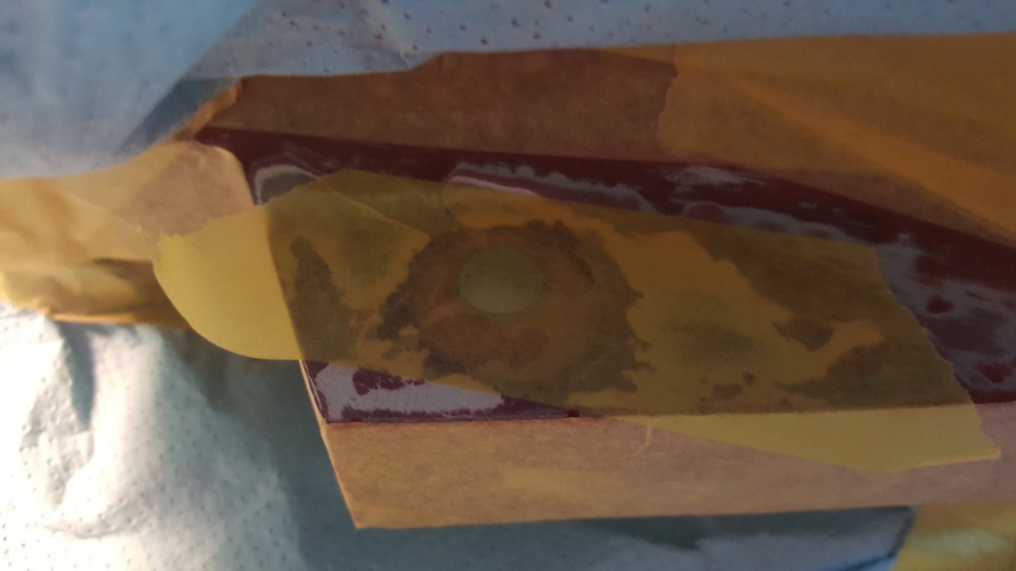
Hello All, Today as well only a short update on the build. During the weekend I primed extensive amounts of detail parts, as well as the rails for the hull. however due to running out of Matt White paint, I suspended further works on these parts. I finished with the stern thruster mounting during the weekend, wen the rain let out a bit. I didn't proceed with the painting of the stern section, because there were a couple of air bubbles in the epoxy filling, that needed to be plugged. This led to one day technological wait, for the epoxy to cure. before painting ca start. Ready for some sanding on painted hull, and sanded using 60 and 120 grit. Finished sanding using 60 and 120 grit, this gave surprisingly smooth surface. And last picture, filled bubbles are taped over, so the epoxy doesn't flow out when the hull is flipped to fill the imperfections on the other side. Cheers George


- 90 replies
-
- 3
-
-
- fairmount alpine
- billing boats
- (and 1 more)
-
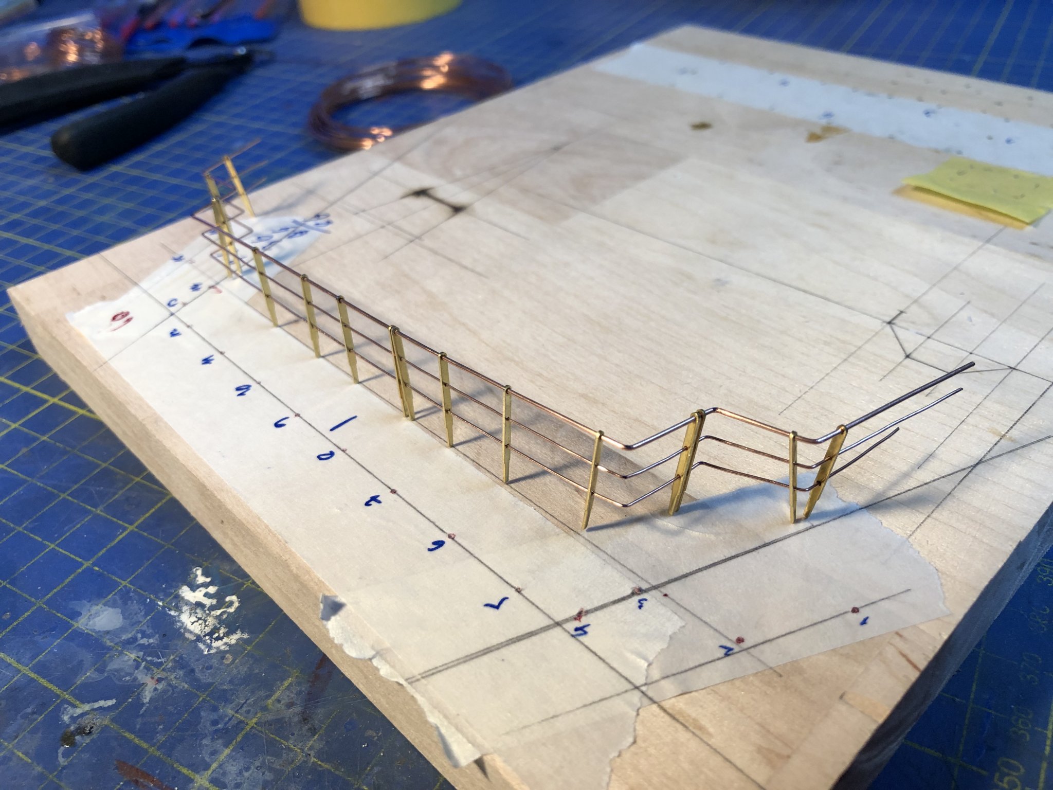
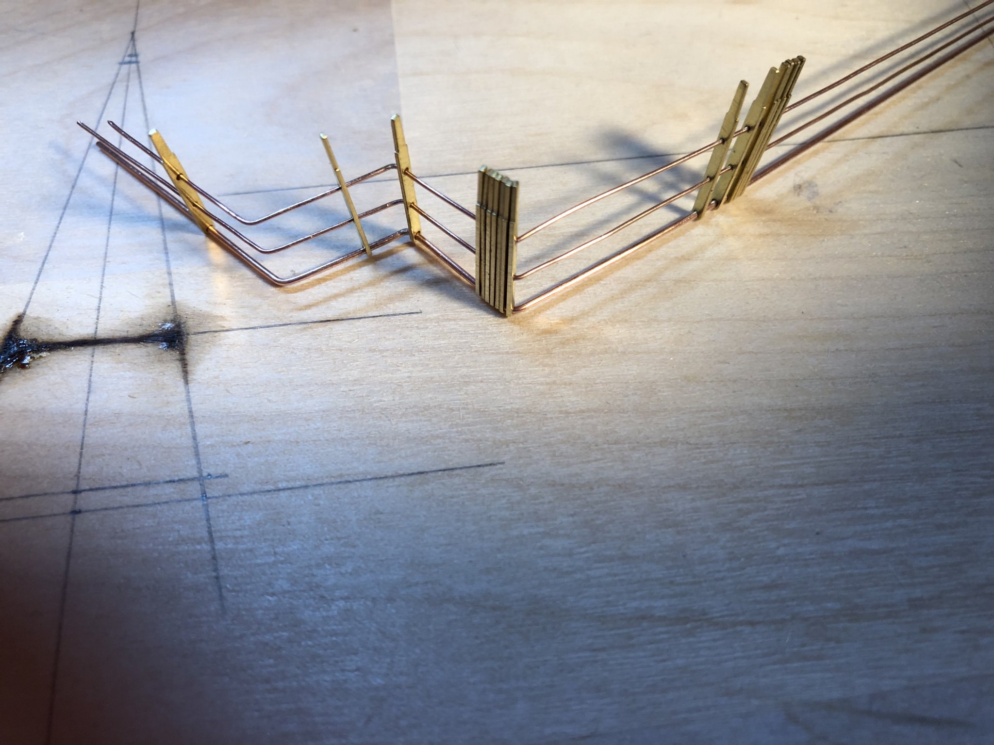
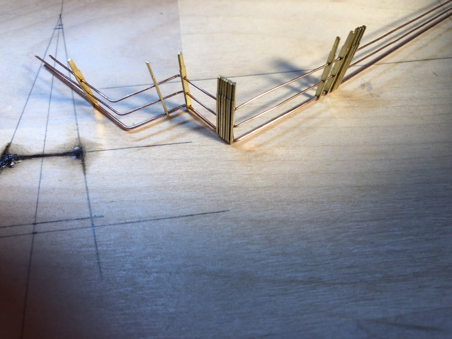
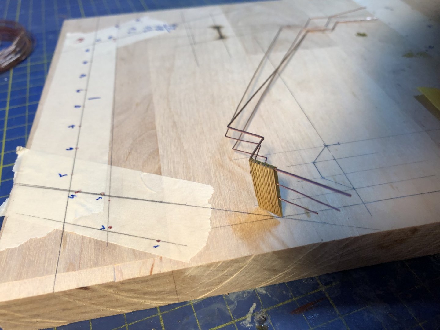
Hello All, today I will do only a short post before the weekend. Just a closer look on the hand rail soldering, I will let the images do the talking. Cheers George


- 90 replies
-
- 4
-
-
- fairmount alpine
- billing boats
- (and 1 more)
-
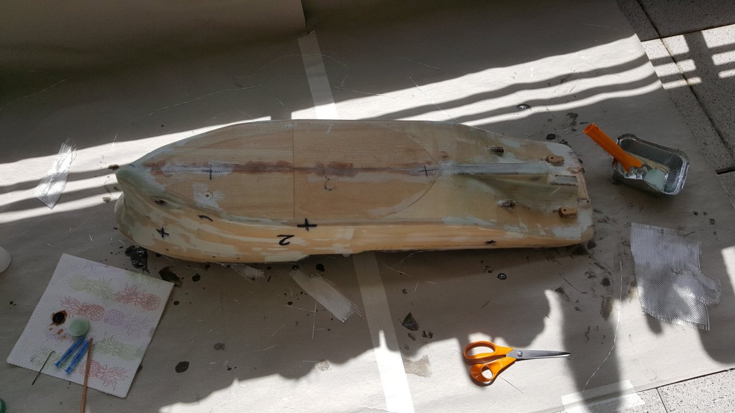
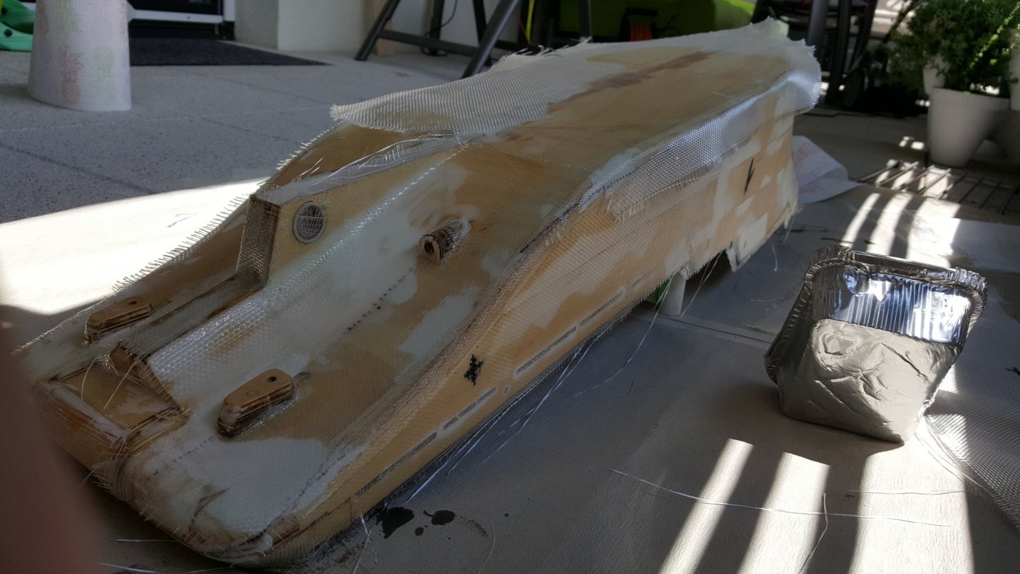
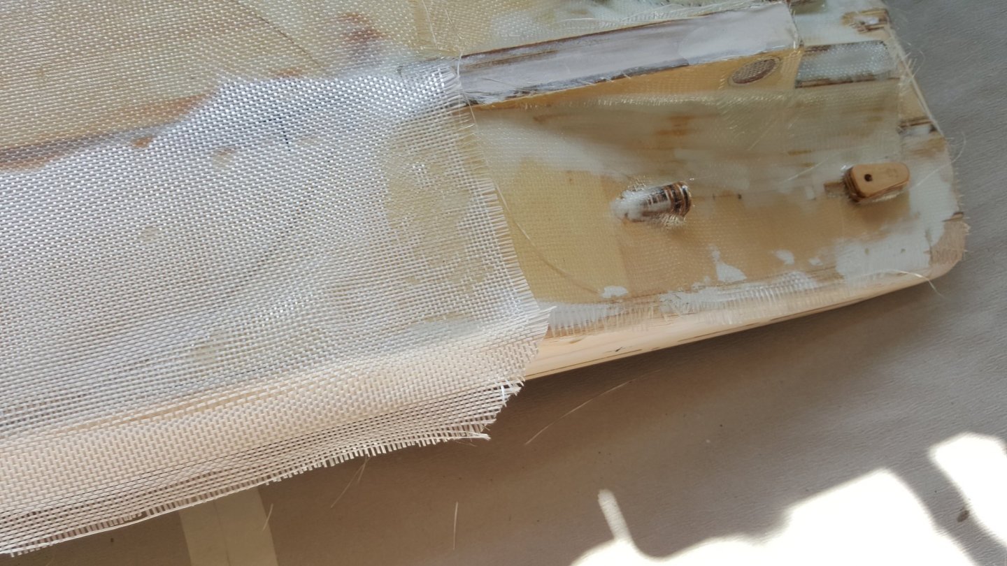
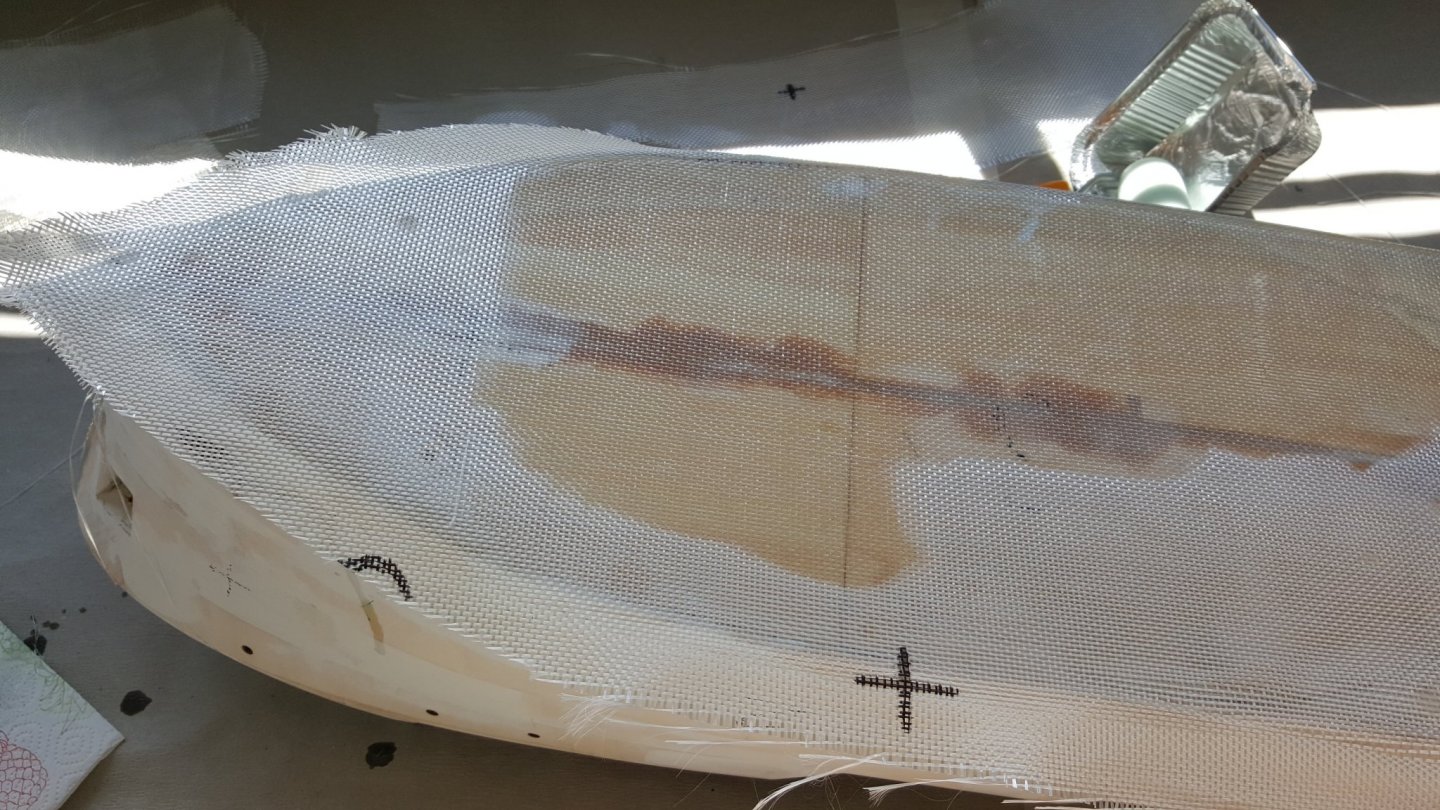
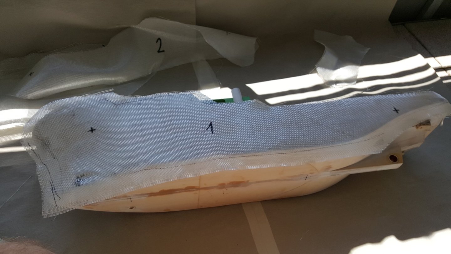
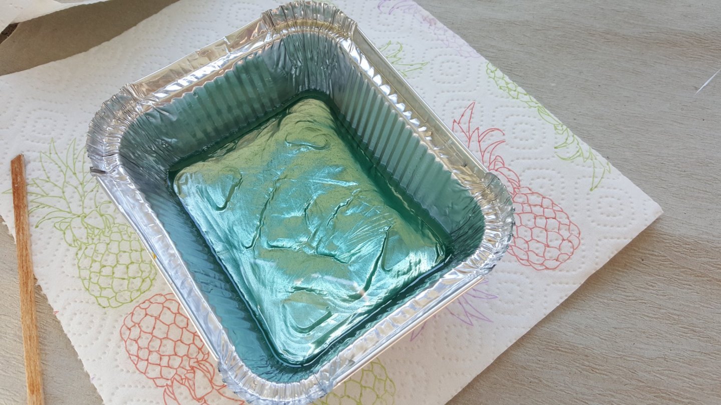
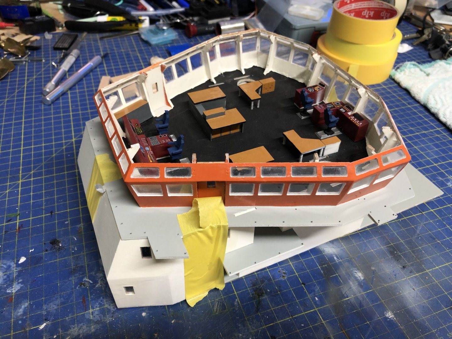
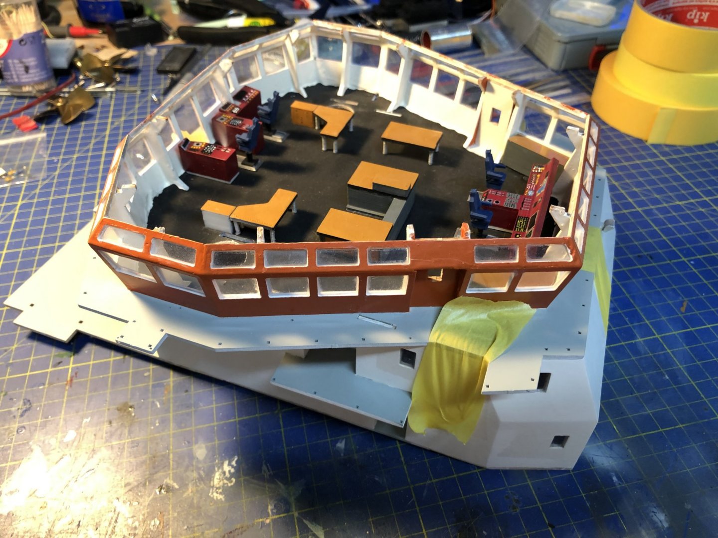
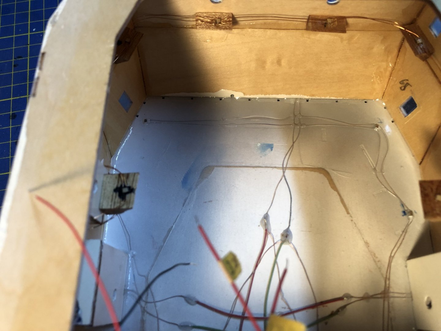
Hey Peter, This flooding was only a freak incident, and shouldn't happen on normal sailing occasion, as the hose will normally be connected to the water pump for the fire monitors. Either way, there will be more water tightness tests following further down the road. Now I found out that only 8kg of lead in the hull are not nearly enough to get it to the desired draft, it wanted at least 5kg more. Also personally I have never seen a model with an actual bilge pump, I think it is quite an over kill. Since we expect some occasional small leaks around the shafts of different propulsion parts, these leaks shouldn't be more than a couple of drops per minute. Any more severe leaks that theoretically could happen should then be from running aground on rocks in high speed, which happens mostly close to shore... But nevertheless I am interested in where you plan to mount the bilge pump, and also regarding the fact, that the hull is sectioned with the bulkheads, which are, as I learned yesterday quite watertight, as the flooding I experienced was only in single hull section, confined by the bulkheads. Also my hull is actually laminated from the outside and smeared with epoxy on the inside, it already survived one "crash test" falling into an empty bathtub, which resulted in some dents in the bathtub, not the hull. Here are some pictures of the process, as i wore gloves, completely covered in the epoxy, I did take only a few pictures, to keep the phone clean. And don't worry I will slow down the build around this weekend, as I am getting to painting of details, and it is almost freezing outside. And the other things, like the coffee corner, and the lighting needs some time. Regarding the coffee corner, it is a good idea to add it in, only I have no idea how it should look like, and where it should be placed. I don't drink coffee du to blood pressure skyrocketing, only tea. Still if you could mark it on one of the pictures, where would be an optimal position for such a thing, and a picture of how it should look like. Also I plan to make some chairs, to add around the tables on the bridge. Regarding the monkey deck, I plan on gluing it on, as either way it would be almost impossible to take it off once all the cables and hoses are in place. Since the LEDs should not burn out as normal lights (that is the theory, usually holds, until one applies higher voltage) there is no real need to access the bridge. Cheers George
- 90 replies
-
- 2
-
-
- fairmount alpine
- billing boats
- (and 1 more)
-
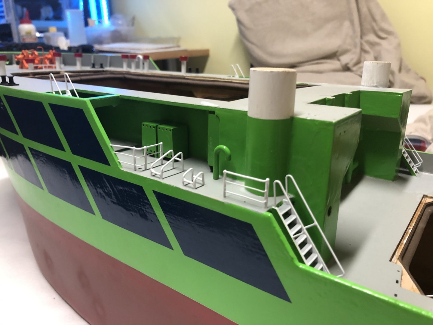
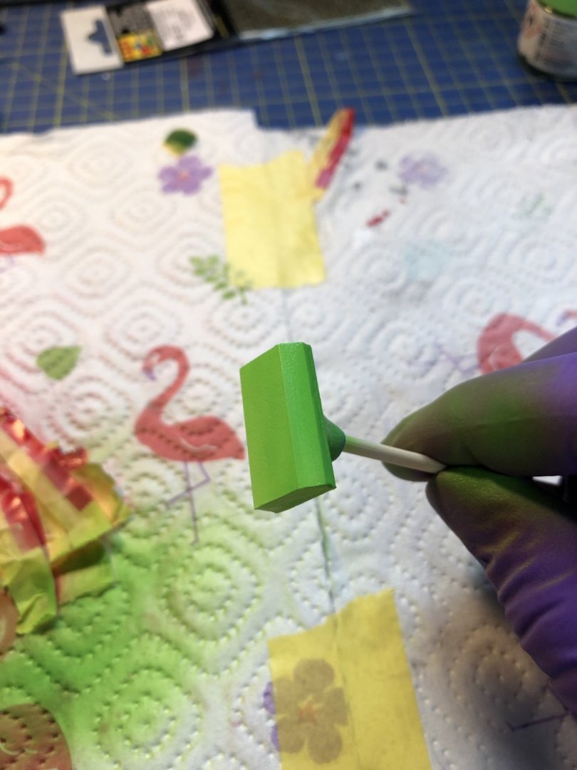
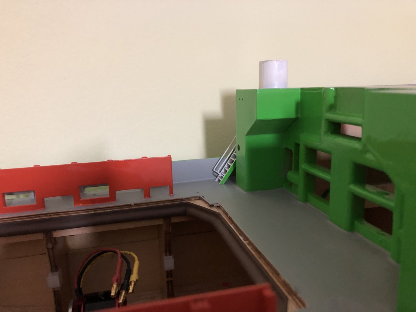
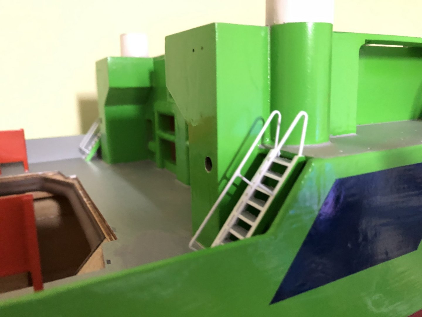
Hello All, So yesterday was a water leak test in the bath tub. This ended relatively well, I almost drowned the model. I didn't observe any leaks through the glue joints, just some minor leak through the stern thruster seal, this will be solved by changing the supplied rubber O-ring for a silicone sealant bead, once I will finish with the sanding of the excess glue. The major leak however happened from water pump inlet, where I put on the inlet hose, but then proceed to put a bag of lead pellets on top of it, so the entire hose ended below the water line, and trouble was born. Now I wait until the hull interior is dried. In the mean time I will most likely work on the details and the superstructure. After the test I went and glued together the first two parts of the superstructure, after I tested all the mounted LEDs, if they work. And lastly pictures of the controversial green sided ladders: I personally think it looks pery good with the green sides, as they are only on the outside, it makes the ladders blend in a bit. Cheers George
- 90 replies
-
- 4
-
-
- fairmount alpine
- billing boats
- (and 1 more)