Modeler12
-
Posts
1,716 -
Joined
-
Last visited
Content Type
Profiles
Forums
Gallery
Events
Everything posted by Modeler12
-
 The most common way is to loosen the collet from the top with a wrench that can turn the spindle. You hold the collet while loosening the spindle. Then you may have to give the spindle a tap with a mallet which should drop the collet down. You can then continue to loosen the spindle until the collet drops into your hand.
 -
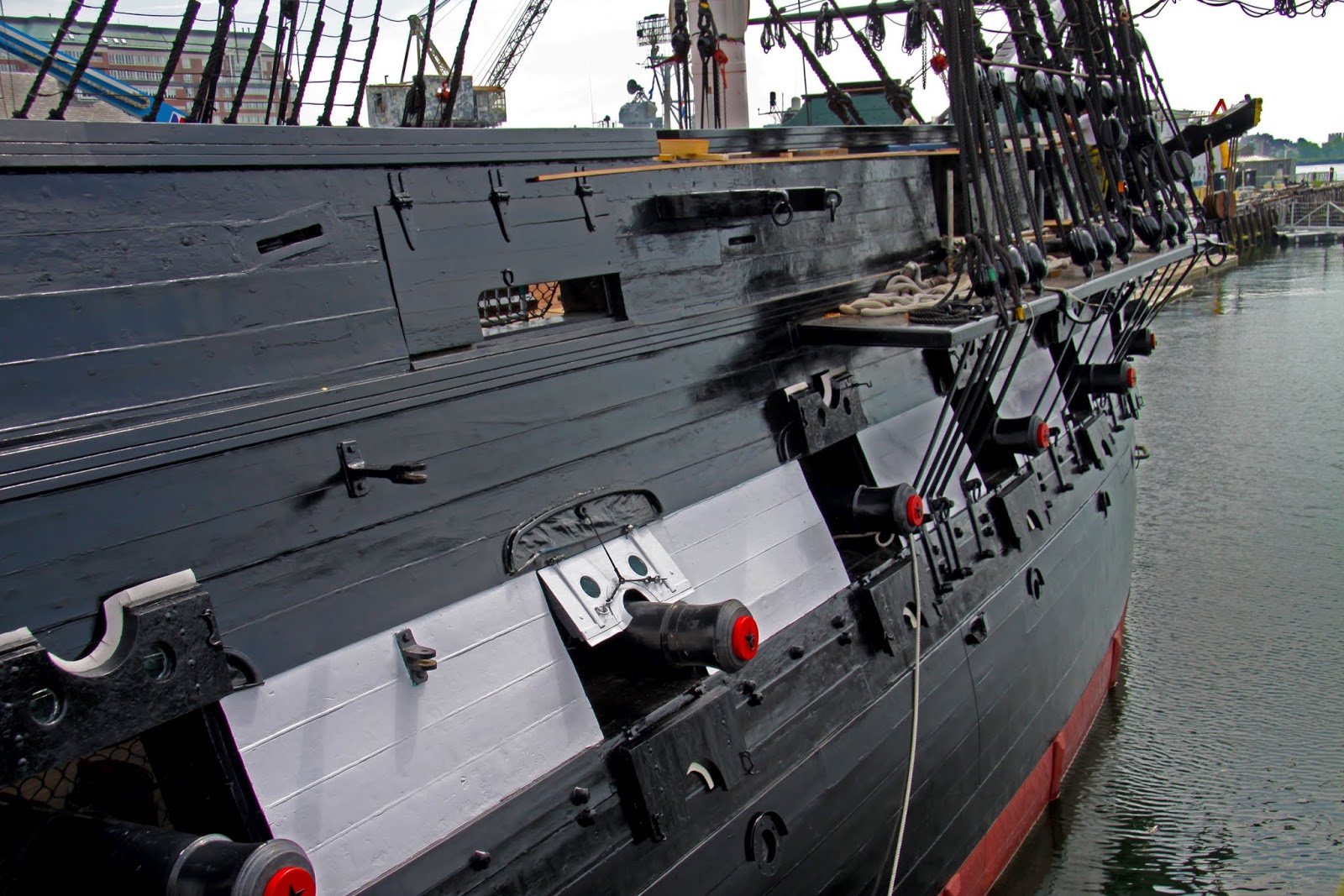
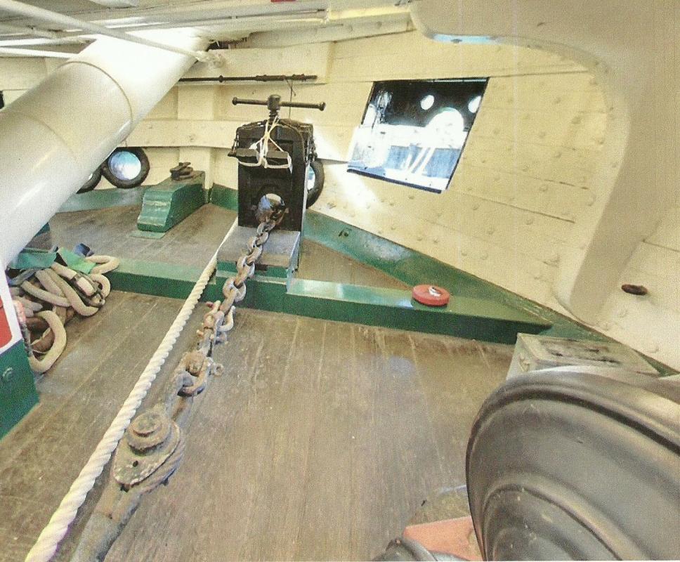
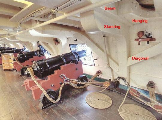
Very interesting, Tom. Again some changes were made after 1812 because the current ship has the two part gun ports near the bow. However, as the picture below shows, the forward opening is almost useless for a gun since there is hardly any room (even before the use of chain instead of heavy rope for the anchor). There is actually a gun mounted at the second opening on the starboard side, but not on the port side). I bet they left it that way so they could say the ship had more guns than she actually used.
- 1,348 replies
-
- 4
-

-
- constitution
- model shipways
- (and 1 more)
-
I like to add one more thing to the excellent advice by Keith the Bear. Chatter can occur when you mill at a slow speed. It will create a rough surface. For milling metals you might also try a lubricant such as some WD40. It is messy but gives much better results. On my mini-mill I usually go high speed with small diameter tools (eg. 5000 rpm for a 1/16 inch bit). I don't take deep cuts on metals but am not afraid to try increasing depths on wood. Burning wood usually means a dull cutter or a wood full of resin. Why pine for small stuff? Try some pear or birch. Go Bears!
-
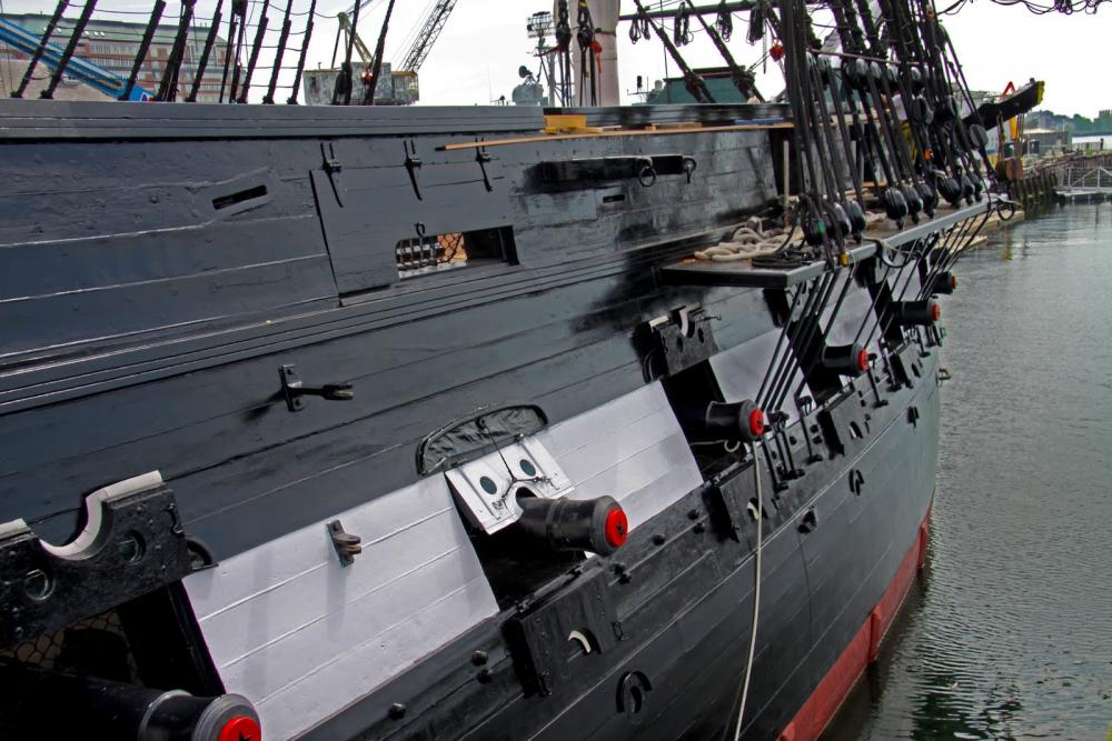
Tom, I am really impressed with the detailed work you are doing. Especially your addition of the gun deck section. I have a question/comment about the gun ports and the doors. Your post 893 on previous page. The plans I have show the two doors, and the picture below does also. You show this correctly for the guns that are nicely visible, but not on the two doors that are closed towards the bow. I know this is a bit of nit-picking, but I was wondering if you are aware of this.
- 1,348 replies
-
- 2
-
-
- constitution
- model shipways
- (and 1 more)
-
Very neat work, Geoff. One small suggestion for the shrouds. You might use a small piece of tape with a number on each one to identify where they go. They will get longer as you go aft and it is easy to mix them up. As they go aft, they also slide a bit aft around the mast. Yours look like they are loose enough to make that adjustment when the time comes. I have used tape intended for identifying electric wire. See https://www.amazon.com/Kableflags-KFA001-Cable-Identification-Blank/dp/B000TO8GGW But you can make your own, of course.
-
Thank you guys. It was not like I was not working on my workbench, but it involved a bit of different 'work'. That is just like me: 'Get involved and work hard', 'Get involved and work harder'. next . . 'Relax and take a trip'.
- 572 replies
-
- 3
-
-
- constitution
- frigate
- (and 1 more)
-
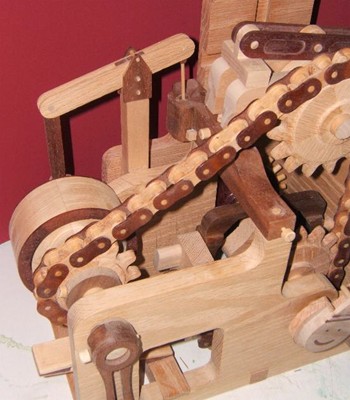
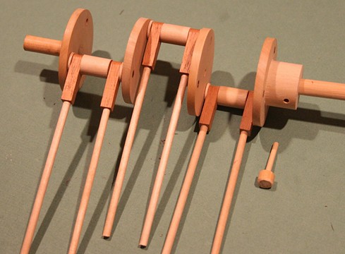
So, I have recharged my batteries and should be able to continue where I left off last December. What happened is that I got side tracked with 'Le Machine' (a wood working project of things that move but don't do anything useful). I'll post some detailed pictures elsewhere, but here is the idea. All wood, no metal, some glue, but mostly wooden pins. I can reassemble all while adding new features. A hand crank to move chain and sprockets, gears, cams, and on and on it goes. Then we traveled some more, took videos and had to spend time to edit and publish them. Then I got lazy . . . . Thanks to some of you who 'reminded' me of MSW. The cross section is still sitting on my work table in the garage like I left it several months ago. Time to get going, Jay.
- 572 replies
-
- 8
-
-
- constitution
- frigate
- (and 1 more)
-
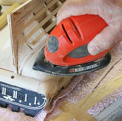
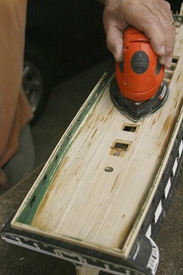
No Mark, the mouse has a flat surface on the bottom and would not work on concave surfaces. Hence is works fine on the outside planking of a hull but not on the inside. I was curious if the mouse is still available. It has changed a bit but is still there at Home Depot for $40. http://www.homedepot.com/p/BLACK-DECKER-Mouse-1-2-Amp-Detail-Sander-BDEMS600/205545909 Be careful of others that are a bit cheaper but don't have the flexible tip.
-
What I have used in the past is a very small sander made by Black and Decker called the mouse. It has a flexible tip (with separate tip sand paper pieces) and does a decent job even on sanding decks. At one time it was sold by Home Depot for about $35 but had a bad review because people were trying to use it as a 'power sander'. PS the second picture was taken when I was not happy with the spar deck planking (not smooth enough) and decided to redo it. Another comment about 'sanding by hand'. It is true that your fingers can feel slight bumps or other deviations better than your eye (sometimes), but that does not imply that you should sand by hand. For areas that should be smooth and continues, use a sandpaper block by hand. I think that is what Mark Taylor was referring to. If you ever have done any bodywork on a car, you know what the finger tips can do for you.
-
I might add that the way the 'foot of the topsail is spread' is by having the sheet of the topsail go through a sheave in the mizzen cro'jack yard and then back to the mizzen mast. The same as all other sheets for square sails above. In addition, having a course sail on the mizzen interferes with the spanker sail and spoils the wind going around the spanker when on a reach. I think that is more of a problem than stealing the wind from the main course. But I may be wrong, Henry.
-
Thanks Greg. Most of it has been fun. But there also have been times where I had to scratch my head about how to proceed. This is one project that I don't want to rush, so I take time out to read, walk and have fun with the admiral.
- 572 replies
-
- 5
-
-
- constitution
- frigate
- (and 1 more)
-
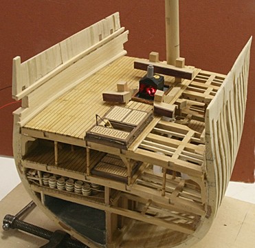
I encountered a bit of a set back. While installing the standing knees and then the diagonal knees I found it almost impossible to align them with the spar deck beams. I was trying to do this without having that deck in place and simply mark the spots. The diagonal knees are supposed to butt up against the spar deck beams, but I had major gaps with the first two and gave up. What I now intend to do is to remove several deck planks on the spar deck and work from above to cut and align those diagonal knees. I hope that makes sense, but it will take some more time. Actually that gives me a chance to do a better job with the spar deck planking since those will be all visible from above. Likewise I want to add a few more short planks along the starboard side front and back. That way I gradually phase into a 'complete' upper deck while still showing the carlings and joists in the center locations. My plan is still to have the upper bulwarks, channels, etc finished on both sides. When I am satisfied with the next step I will open up the starboard side.
- 572 replies
-
- 6
-
-
- constitution
- frigate
- (and 1 more)
-
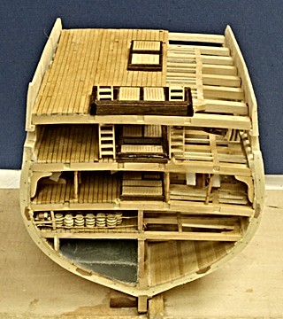
I'll take the above suggestions in consideration. Thanks to all of you. But it comes later. Meanwhile I have dry-fitted the spar deck so I can determine where those beams go before I install the knees on the gun deck. Keep in mind this is all loose - as you can see by the slanted ladders (which were also made well in advance). The proposed 'half-gun assembly' would be located on the gun deck to the left of the slanted ladder. Of course not yet included are the mast, chimney and many other details.
- 572 replies
-
- 9
-
-
- constitution
- frigate
- (and 1 more)
-
Well, you guys are posing too much of a challenge not to give it a try. My thoughts are to make the barrel out of wood, mill it in half and paint the outside black and the metal cross section grey with some 'grain'. I will simply have to use some glue to hold this part in the saddle, etc. All of that is in a very small scale so quite a tricky operation. Don't hold your breath because I have lots of other work yet to be done.
- 572 replies
-
- 5
-
-
- constitution
- frigate
- (and 1 more)
-
I thought about that also and maybe I could hold the half up by gluing the breach line (on the other side) down to the deck. It would be interesting to show the inside of the bore with powder cartridge and cannon ball in place. I do have some cannon balls, but am not about to try to cut those in half. Cutting the cannon and carriage in half is just a crazy idea, but I am not throwing it out of the window, yet.
- 572 replies
-
- 4
-
-
- constitution
- frigate
- (and 1 more)
-
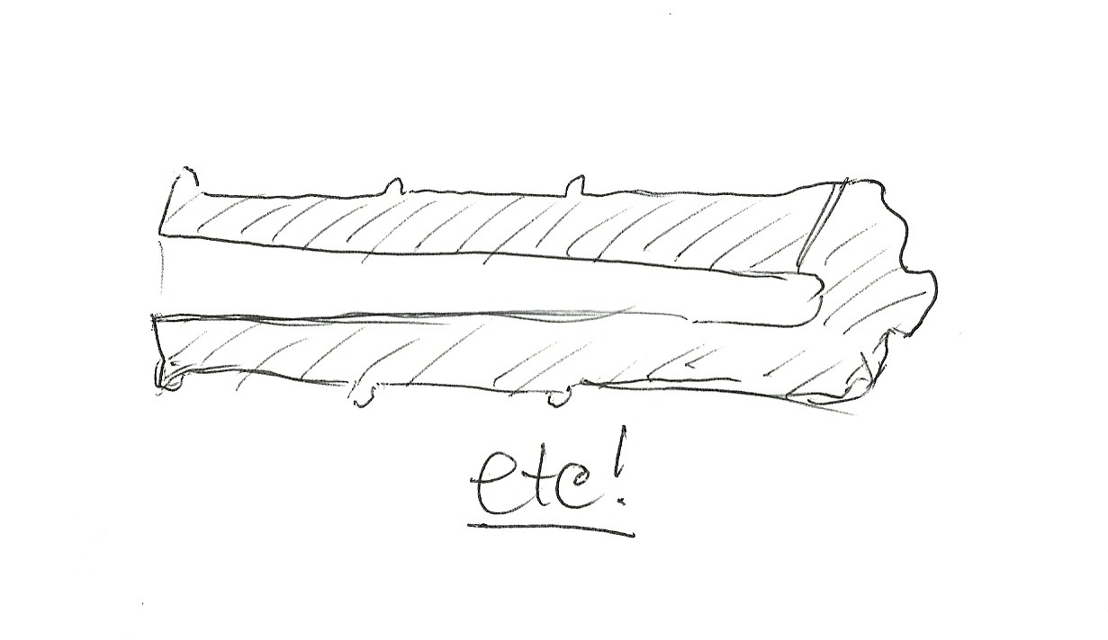
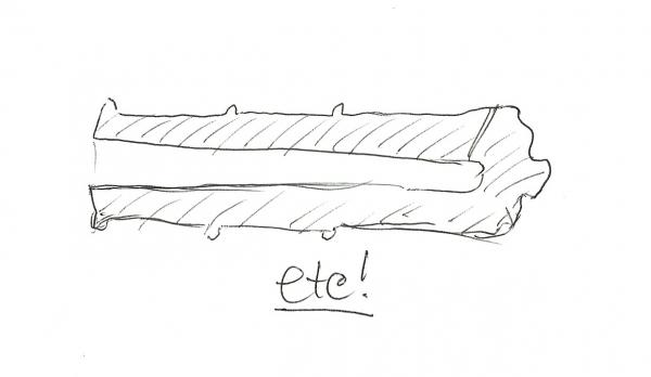
Has anyone ever done a cross section of a gun and carriage? My section would have one gun port right in front and it is cut in half. That means the gun and carriage should also be cut in half, right? I mean length wise. I know this is a crude sketch and the barrel should have a straight bore . . . ., but what about the carriage? MMMMM?????
- 572 replies
-
- 2
-
-
- constitution
- frigate
- (and 1 more)
-
Thanks Dave, I am aware that when I post pictures I could increase the pixel count, but some time ago I decided to keep it to where I simply crop to the size you see (5 inches vertical in most cases). In the case of post 504 I just wanted to show the overall layout before it is finished. Later I will show the gun deck up close, but it is far from finished. Likewise the front has a lot of wood sticking out and needs to be trimmed flush, and other such details. In fact, I am removing the planking along the port side because I had trouble cutting the gun port holes. I need to reinforce the frames, cut the opening from the outside first (add the horizontal parts) and then cut the planking to fit the openings. Just like you (and I) did on the full size models.
- 572 replies
-
- 3
-
-
- constitution
- frigate
- (and 1 more)
-
I find it interesting that a soft wood like balsa is harder to cut accurately and uniformly than a hardwood like pear or boxwood. The problem with balsa is that the fibers are large (even though they are spaced apart to give it the low density). To cut balsa across those fibers is easier than cutting them at an angle or slightly off center. Likewise balsa does not sand nice and smooth like a hardwood. It should be kept for fillers as Mark suggests or for really lightweight places like model airplane frames. I might add that cutting balsa with an Exacto knife is not as good as using a razor saw. Again it is a matter of cutting those fibers and a saw does a better job than a knife.
-
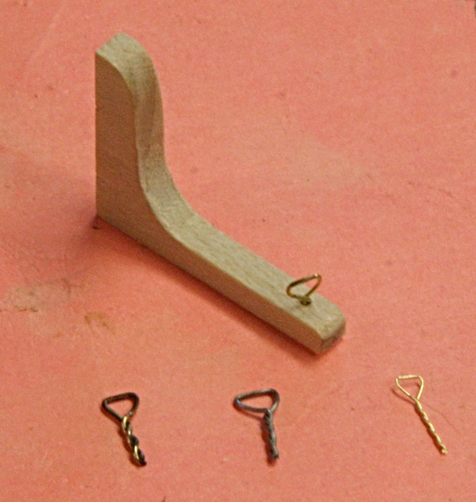
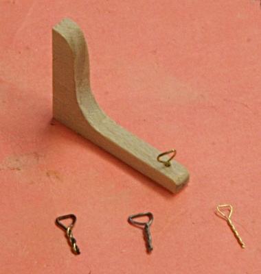
Correction The 'eye bolts' shown above were too heavy, too thick. So I tried a couple more using some steel wire (of the same thickness, 0.015 inch), brass at 0.012 inch (28 gauge) and brass at 0.007 inch (32 gauge). I think the 28 gauge looks about right. I will also use that gauge to make the hooks and probably go down to 2.5 mm for the blocks. That translates to 7.5 inches full scale.
- 572 replies
-
- 8
-
-
- constitution
- frigate
- (and 1 more)
-
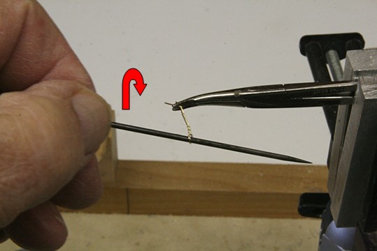
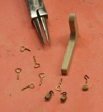
Eye bolts for the gun tackles After the knees were made, I decided to add the eye bolts that are fastened to the standing knee and hold the double blocks for the gun tackle. There two, one for each gun as shown in the photograph above. I figured those are easier to install on the bench. To make the 'eye bolts' I used some 0.015 inch thick brass wire, made a loop and inserted a steel pin. That was rotated to twist the wire and make an eye. Using a pair of pliers, I flattened the end as if there are two hoops. They still need to be blackened. The two blocks I show are 3mm and have the hook and strop soldered on and then the wire was blackened. That's why the dark color. I have also made these by making the hook separate, drill a hole in the end of the block and glue the hook directly into the block. All of that will come later when I make the gun carriages.
- 572 replies
-
- 8
-
-
- constitution
- frigate
- (and 1 more)
-
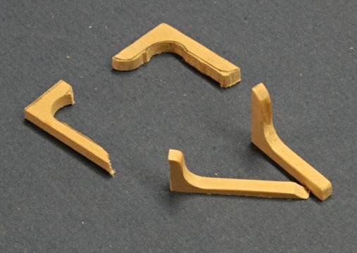
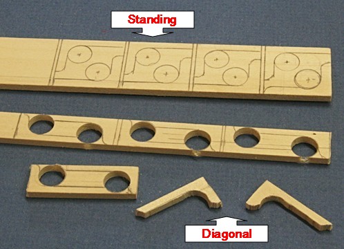
Here is the before and after filing and sanding. The long legs still have to be cut to length and the short leg of the diagonal needs to be beveled. But that will be done during final fitting and glue-up.
- 572 replies
-
- 10
-
-
- constitution
- frigate
- (and 1 more)
-
Jud, I think I understand what you are referring to, however, keep in mind that the pieces I show are cut roughly to shape. A lot of filing and sanding will smooth out those transitions and make them look like the real thing (I hope). I should add one more comment about the thickness of the knees. A real closeup of the real ship indicates that the legs of all knees that are against the bulwarks are really against the frames and the inside planking was added afterwards. Structurally that makes a lot of sense but for my model an impossible task. Hence those legs will be filed thinner and glued against the planks.
- 572 replies
-
- 6
-
-
- constitution
- frigate
- (and 1 more)
-
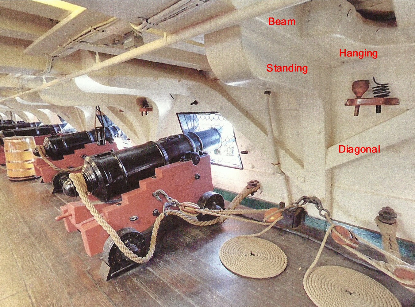
Thanks Albert. Knees The gun deck has several knees to support the spar or top deck. They straddle the gun ports and for the most part are all slightly different in size and shape. Hence I will have to sand and fit each one individually. There are standard or standing knees and diagonal knees. The hanging knees will be attached to the bottom of the spar deck beams. But they all meet as shown in the picture below. To make them, I used pieces of 1/8 inch thick wood, laid out the basic shape, cut the hole and band-sawed the pieces. Some sanding will clean them up and then they will be sanded to fit around the gun port holes and meet the standing knees.
- 572 replies
-
- 8
-
-
- constitution
- frigate
- (and 1 more)
-
Thanks guys and happy Thanksgivings to you also. Actually we are having two hens instead of turkey this year, and there will only be three of us. I would be afraid to see the inside too closely, David. Those hammocks are not too pretty. When I finally open up the side I will have a lot of 'adjusting' to do.
- 572 replies
-
- 6
-
-
- constitution
- frigate
- (and 1 more)
-
Update It has been a while since I worked on this model. But slowly I am getting a few things done on the gun deck. The deck is finally glued in place and I am starting the structure above it for the spar deck. I did include the stairs going down to the berth deck and added one of the stantions and railings. I also decided to cut the aft riding bit in two so you can see the stove and the fire inside better. All of this is still loose (as you can see with the two pieces of the aft riding bit). However, there are a few things yet to be done before it all comes together. The bulwarks need to be finished and knees installed, after I cut the gunport holes. Then I have to make and install the guns. So, give me time.
- 572 replies
-
- 14
-
-
- constitution
- frigate
- (and 1 more)