Srodbro
-
Posts
287 -
Joined
-
Last visited
Recent Profile Visitors
2,078 profile views


-
 Bill Morrison reacted to a post in a topic:
Red Jacket by MrBlueJacket - FINISHED - BlueJacket Shipcrafters - Scale 1/8" = 1' (1:96)
Bill Morrison reacted to a post in a topic:
Red Jacket by MrBlueJacket - FINISHED - BlueJacket Shipcrafters - Scale 1/8" = 1' (1:96)
-
Srodbro reacted to a post in a topic:
Charles W Morgan 1841 by toms10 - FINISHED - 1:96 - POB
-
Canute reacted to a post in a topic:
Yellow Boxwood from Model Expo
-
thibaultron reacted to a post in a topic:
Yellow Boxwood from Model Expo
-
mtaylor reacted to a post in a topic:
Yellow Boxwood from Model Expo
-
Any words of wisdom regarding the veracity of other woods they sell, like Cherry or walnut?
-
Srodbro reacted to a post in a topic:
Gjoa by Papa - FINISHED - Model Shipways - 5/32” = 1’ - old solid hull kit
-
Srodbro reacted to a post in a topic:
Charles W Morgan by Papa - FINISHED - Model Shipways - 1/64th scale
-
mtaylor reacted to a post in a topic:
Help with translation of rigging term
-
Harvey Golden reacted to a post in a topic:
Help with translation of rigging term
-
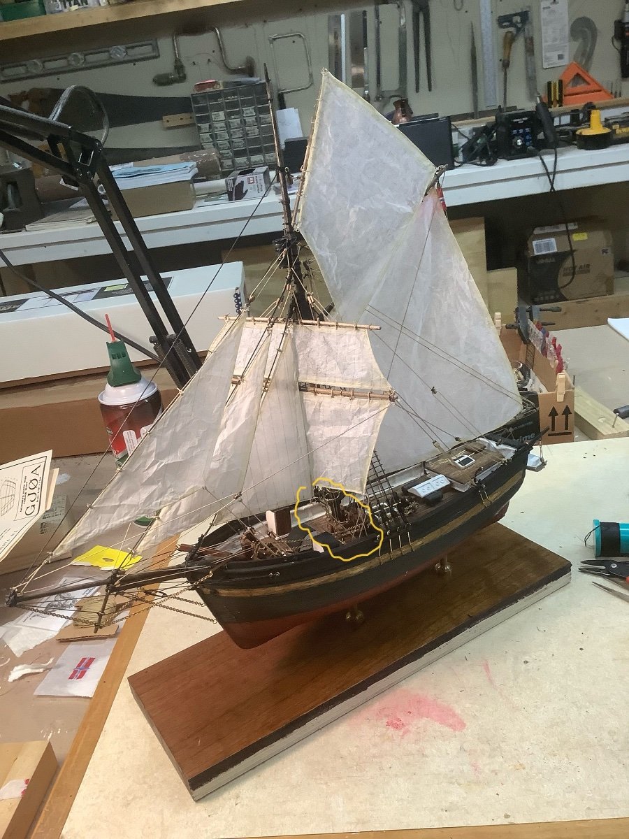
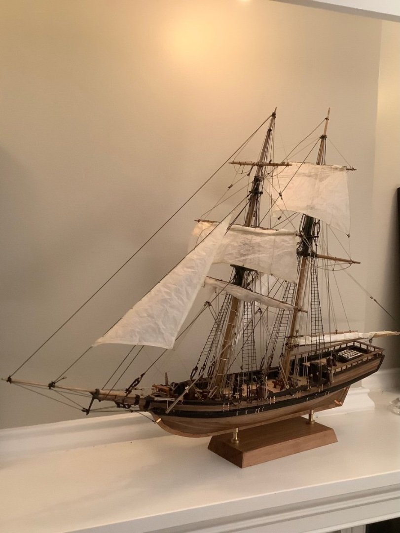
I recently completed my version of Gjoa, which I did with sails. I had the same question about that item, and as near as I could tell it is where the sheet of the fore staysail attaches to the rail traversing the deck forward of the mast. I think the term comes from the idea that this line would “ slap” from port to starboard ( or vice-versa) while tacking. Here is a not so clear pic of my model with the subject circled in yellow. At least, that is how I interpreted it. Though, keep in mind my Norwegian is limited to “ Aquavit” and “Skol”!

-
Srodbro reacted to a post in a topic:
Charles W Morgan by Papa - FINISHED - Model Shipways - 1/64th scale
-
mbp521 reacted to a post in a topic:
SS Benjamin Noble by Roger Pellett - 1:96 - Great Lakes Freighter
-
Canute reacted to a post in a topic:
SS Benjamin Noble by Roger Pellett - 1:96 - Great Lakes Freighter
-
Srodbro reacted to a post in a topic:
Charles W Morgan by ESF - Model Shipways - 1:64
-
 Roger Pellett reacted to a post in a topic:
SS Benjamin Noble by Roger Pellett - 1:96 - Great Lakes Freighter
Roger Pellett reacted to a post in a topic:
SS Benjamin Noble by Roger Pellett - 1:96 - Great Lakes Freighter
-
mtaylor reacted to a post in a topic:
SS Benjamin Noble by Roger Pellett - 1:96 - Great Lakes Freighter
-
I am always blow-away by the micro-soldering skills on these forums. Wonderful work!
-
Srodbro reacted to a post in a topic:
US Brig Niagara by Usgecko - Model Shipways
-
Srodbro reacted to a post in a topic:
US Brig Niagara by Usgecko - Model Shipways
-
Srodbro reacted to a post in a topic:
Charles W Morgan 1841 by toms10 - FINISHED - 1:96 - POB
-
Srodbro reacted to a post in a topic:
Gjoa by Papa - FINISHED - Model Shipways - 5/32” = 1’ - old solid hull kit
-
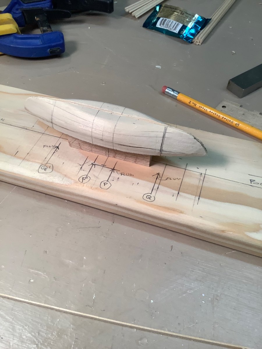
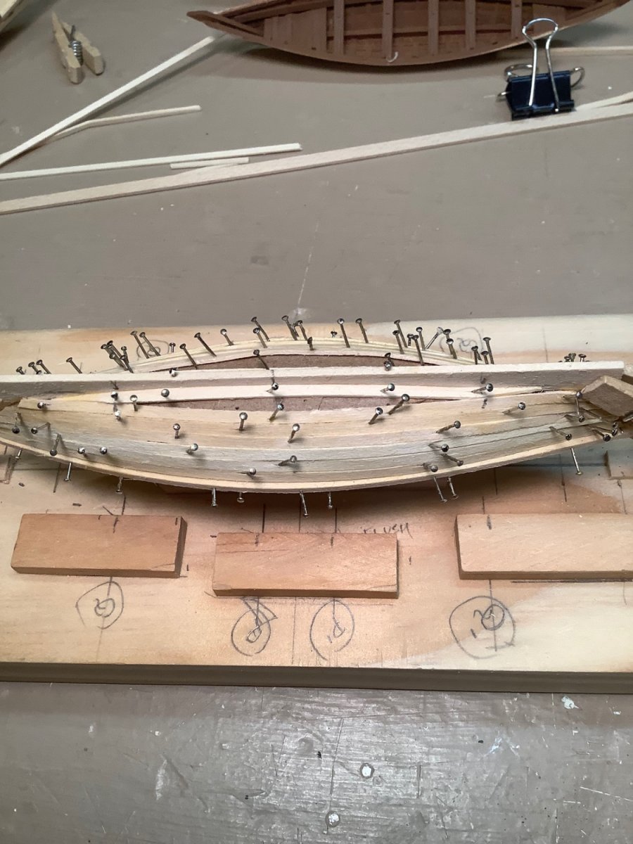
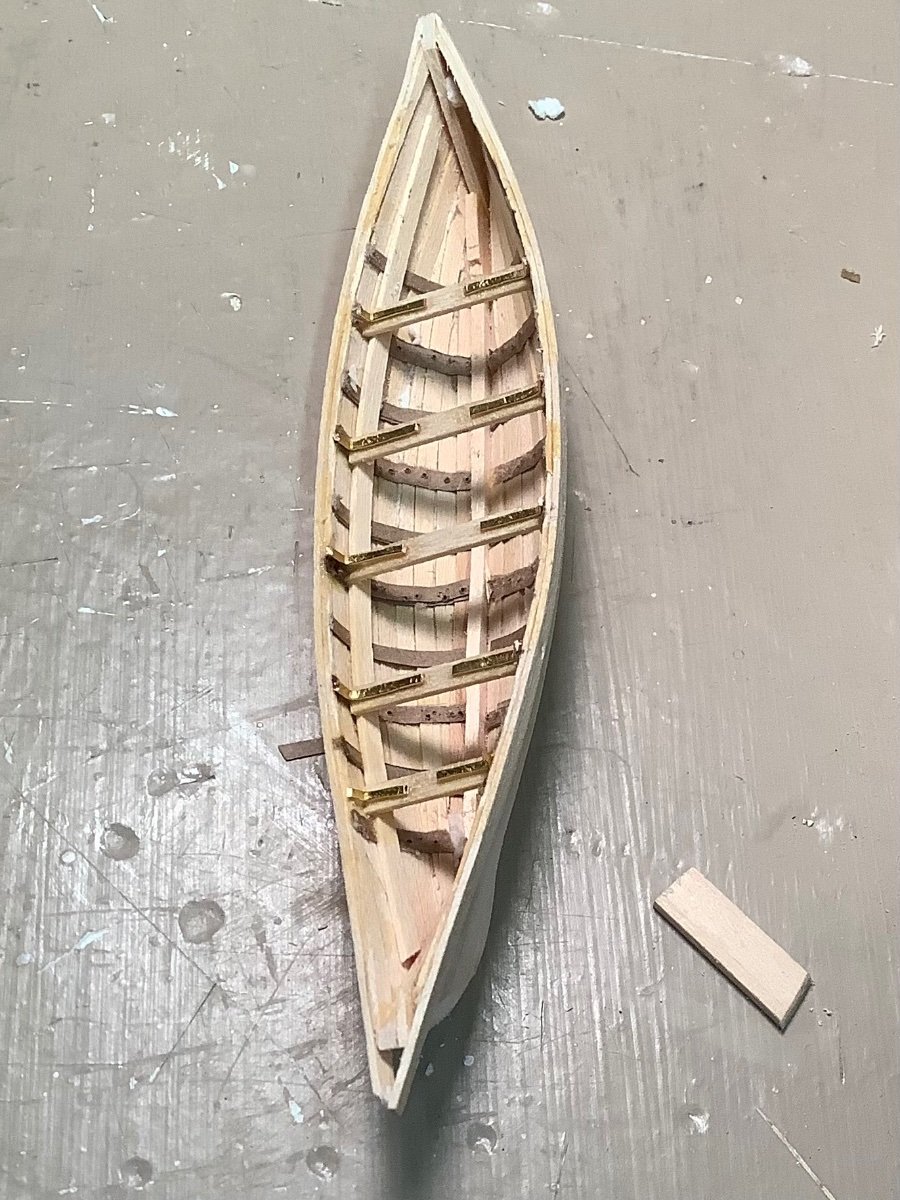
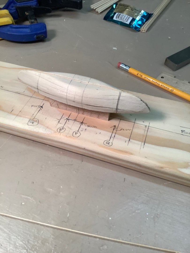
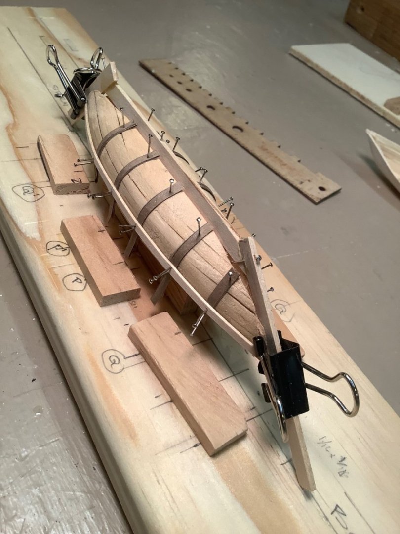
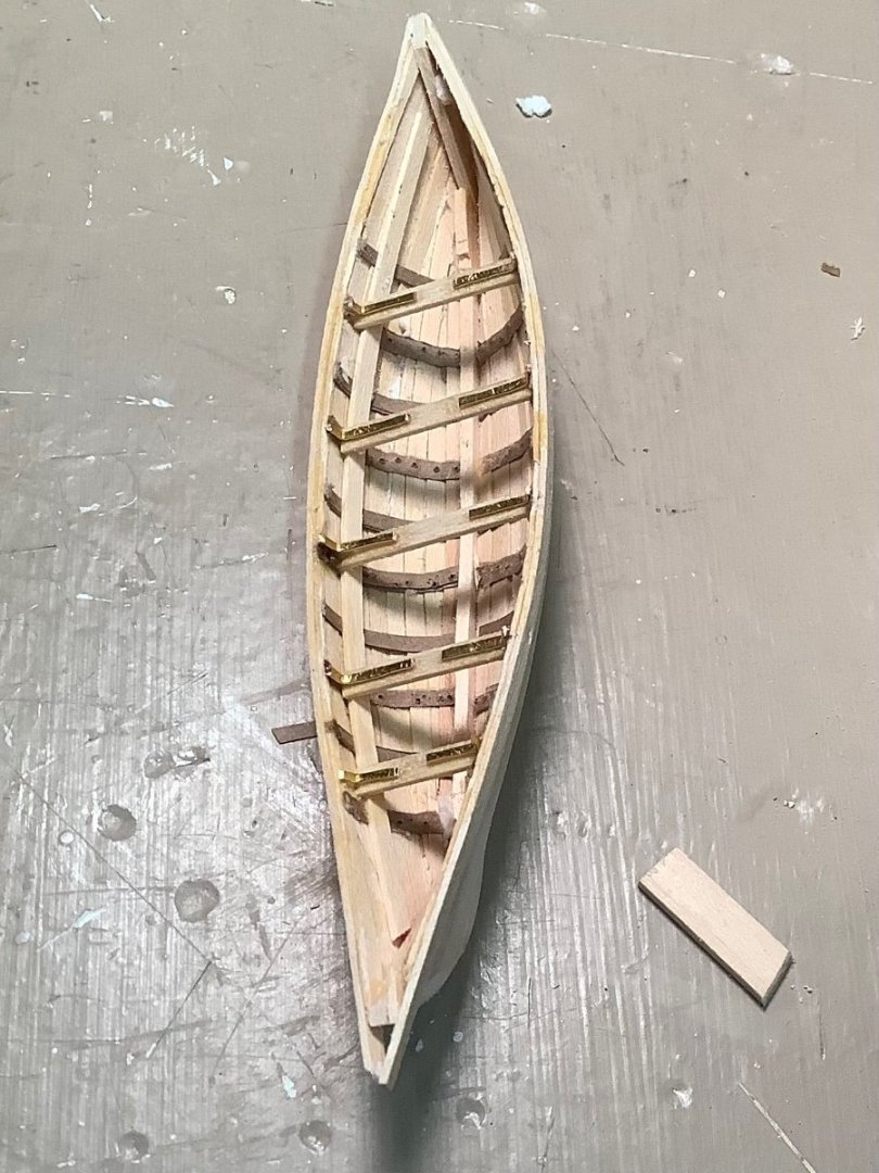
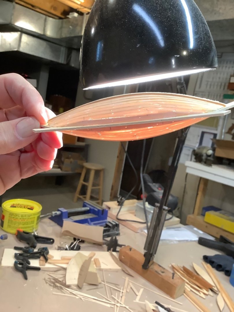
Your boats are progressing nicely. I am concurrently building Morgan and Kate Cory whalers, and decided to first build all the boats for both (like 12 of them). There are some really good examples of whaleboats built by other modelers on these forums, and I cannot dare to compare in the finished quality. I have never had success at grinding/ sanding the interior of these small boats ( uneven, poke-thru’s). So, I used a different methodology. Using the lines provided on the kit drawings, I built a mold upon which I assembled keel and paper ribs, then planking. Filling and sanding gave me a thin hull. Now, honestly I used the center “ scrap” portions of the laser cut boat parts for my mold pattern, so dimensionally I am not super accurate. Nonetheless, I found it sufficed for my purposes. Now, my craftsmanship is far below that of others, but with a bit more patience and skill, and attention to detail ( like more attention to uniformity and number of ribs, etc,) I think this methodology used by the right hands, could be a viable building alternative. Just a suggestion. Love following your progress.

-
Srodbro reacted to a post in a topic:
Charles W Morgan by ESF - Model Shipways - 1:64
-
Missing your posts. Great work.
-
When drilling holes in, say, a farelead, ….several aligned holes in a small piece of wood, or a hole near the end of a piece subject to splitting, I’ve had luck first coating the wood with CA, letting it dry, then drilling. Drill first with your finest bit, then enlarge. Seems to form a chemical matrix on and in the wood that reinforces it. But, consider how you want to finish the piece, since stain won’t agree with the CA. Good luck.
-
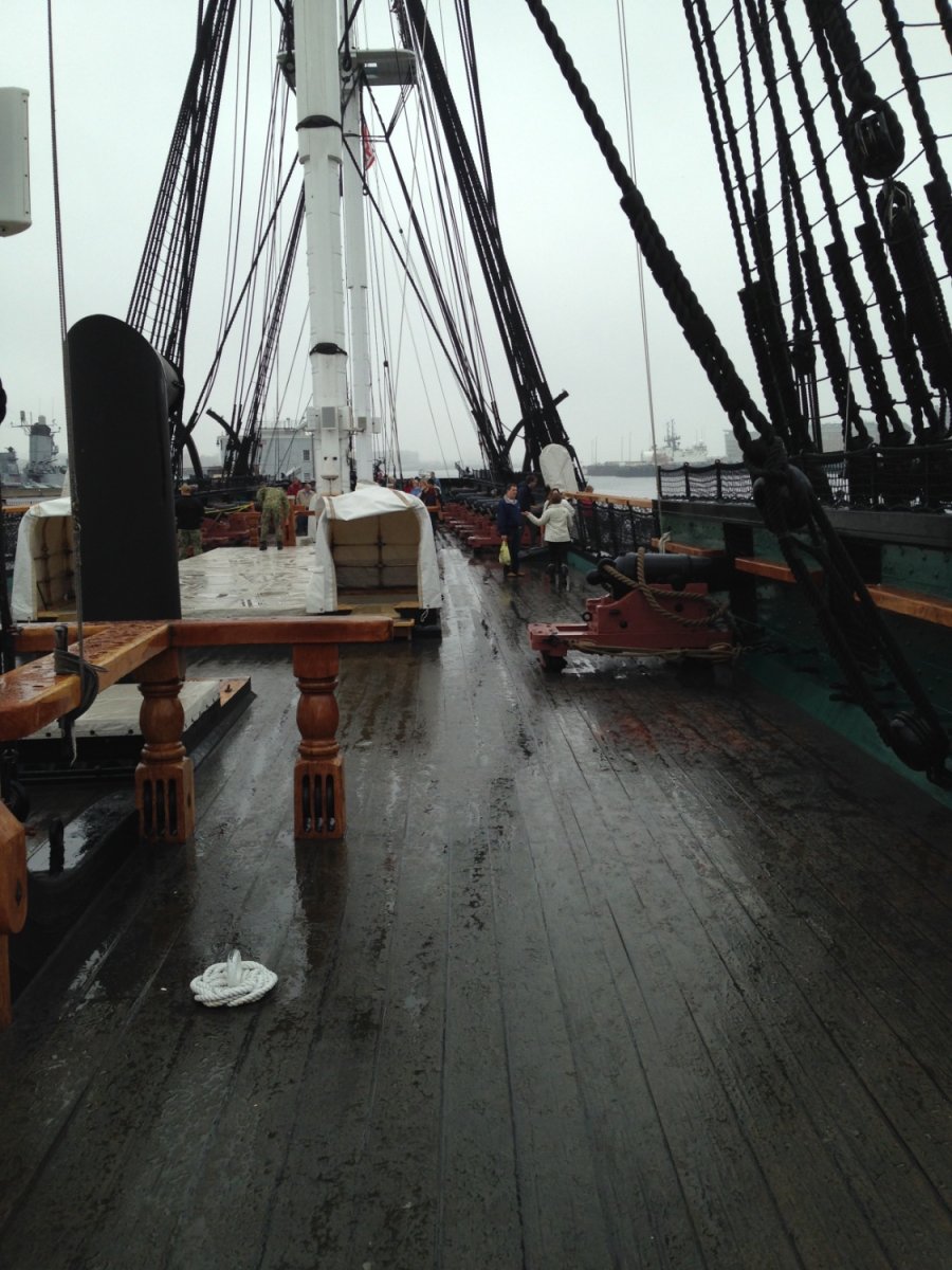
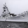
The model color looks pretty close to the color it was in 2018 when I took this pic. Tho, the light level may affect the perception.

-
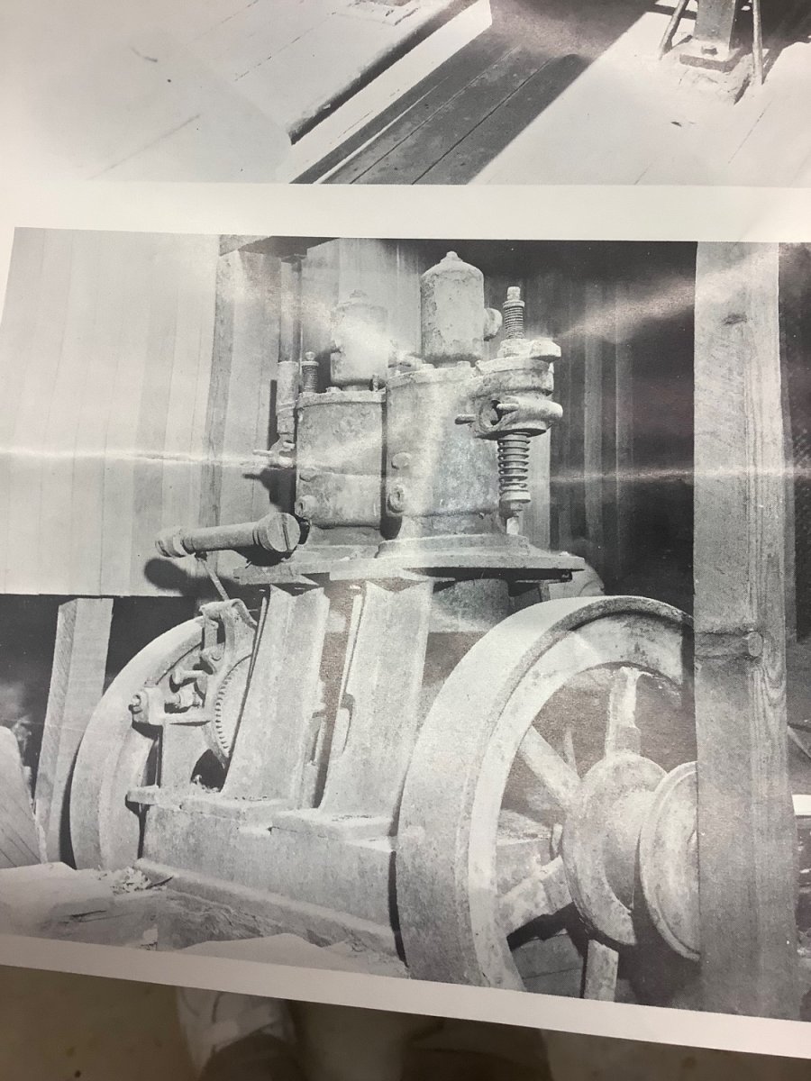
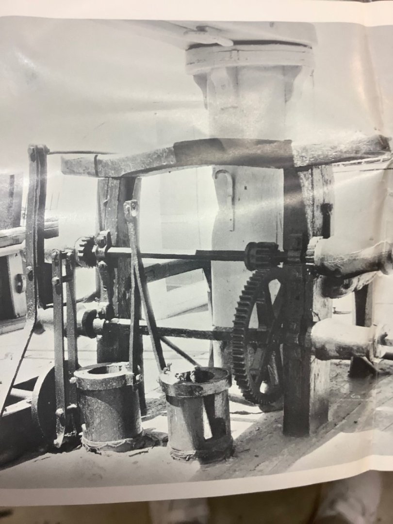
Another pic from the kit is of the Dan engine. This view appears to be looking aft. At the fore end ( right of the pic) adjacent to the flywheel is a sheave that on the model drawings is identified as a chain drive … which would have a chain rising to a mate above, thence to the drive shaft that extends forward to the after most windless. Just guessing that the diameters of all the gears in the drive train to the pumps results in the pumps operating at about 60 strokes per minute ( the rate that might be reasonable for hand pumping? I can’t imagine that rig stroking at a much higher rate), then, working back to the engine and seeing not many reductions thru the various gears and chain wheels, the engine RPM must have been very low, maybe 120 RPM. I wonder if the propeller, driven from the aft end of the engine, would have turned at this low RPM as well. This sketch is what I understand Wefalck describing at the pumps.


-
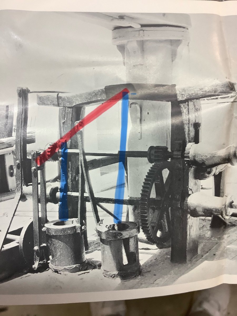
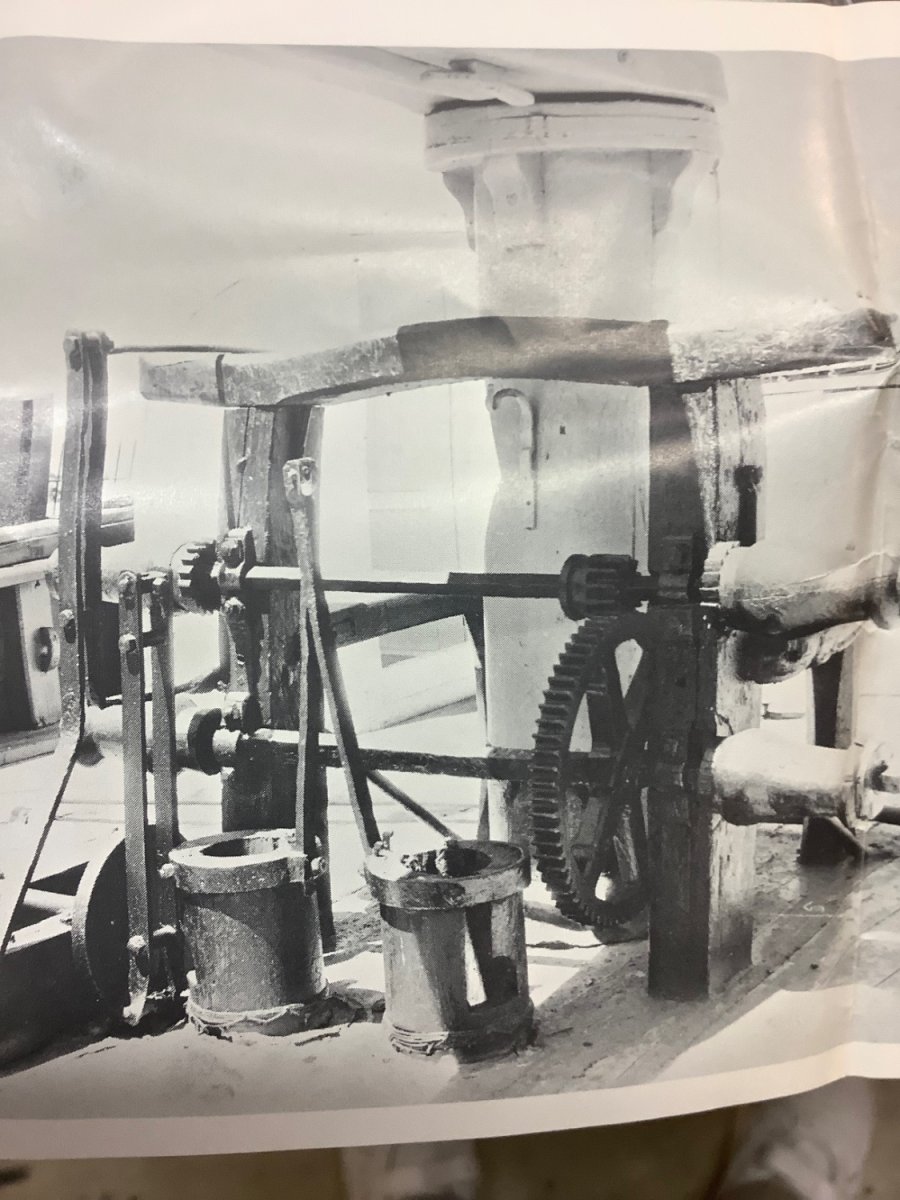
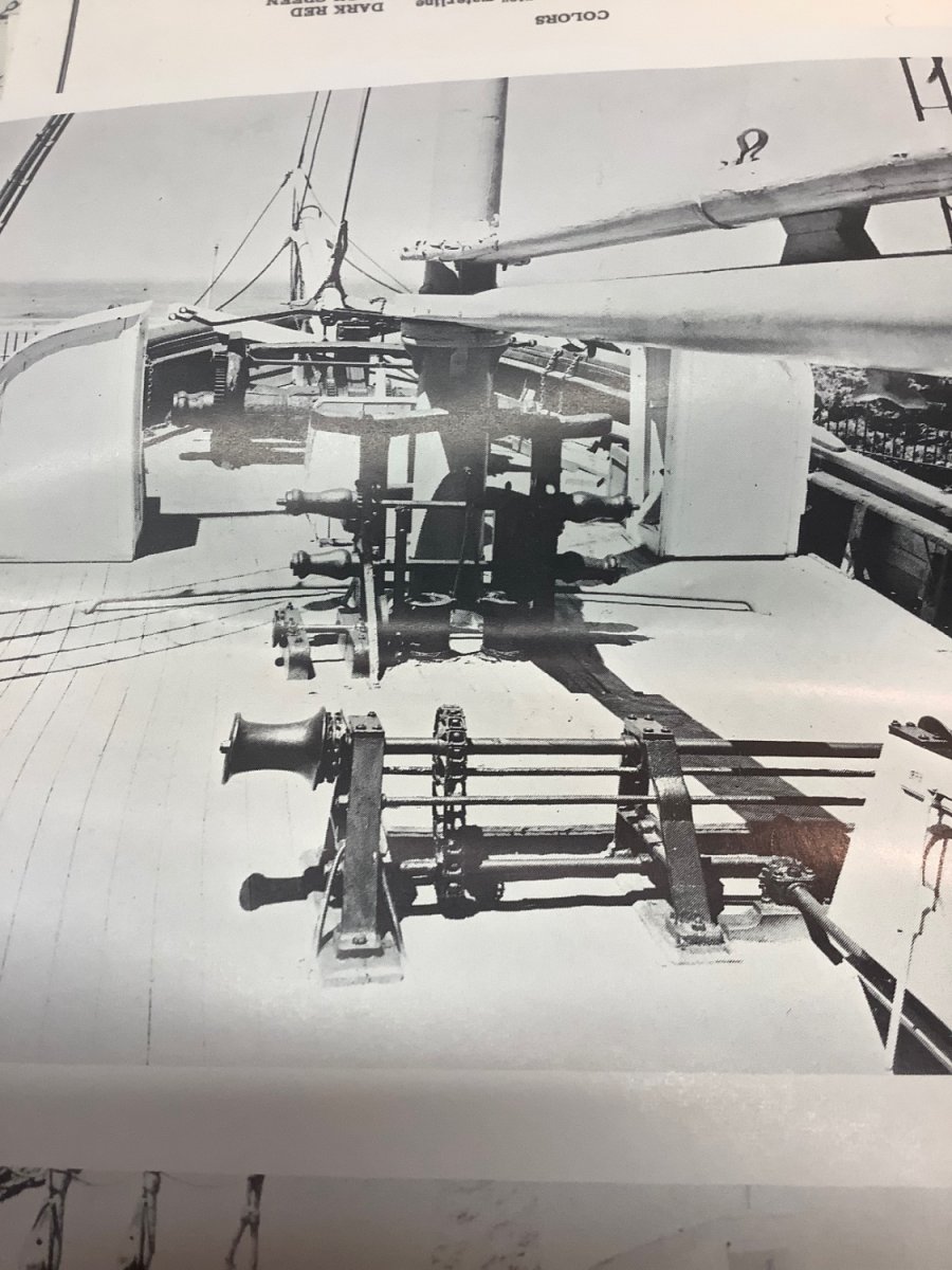
Don’t know if you have these pics … they were included in my Model Shipways kit. In the upper pic, it looks to me that the upper shaft ( of all that equipment just ahead of the pumps) can be engaged-disengaged from the large gear on the lower shaft by sliding the open ended gear at the starboard end of the upper shaft. Also, it appears that the chain gear ( on the aft windless, just inboard of the portside barrel), the chain gear on portside of the assembly near the pumps, and the chain gear on the upper shaft of the forward windless, all three align. But, while I can imagine a drive chain running from the chain gear on the aft windless all the way forward to the main windless upper shaft, and a separate, shorter chain used to run from the aft windless to the portside chain gear on the shaft near the pumps; I can’t imagine how any power is transferred from the shafts driven by the chain to the two shafts just forward of the pumps.

-
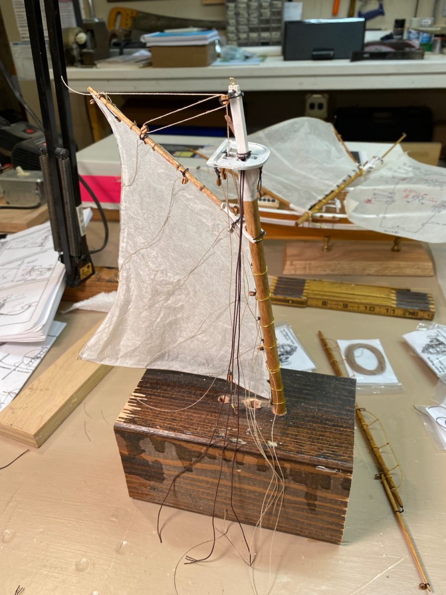
I like the look of silkspan sails. I fabricate them using fine brass wire for the bolt ropes, which then allows forming the sail as “ billowing” as you like. I also prefer to mount them off-model, since my ham-fisted hands have difficulty accessing the yards if on the ship. I also found that, if modeling furled sails, to use about one-third less material, as even with silkspan the furled sail seems too bulky otherwise. But, to each his own. My models are not “ museum quality”, just good enough for my shelf. Have fun.

-
Stuart: Have fun with your Niagara. To the references already mentioned, I would add A Signal Victory by David Skaggs and Gerard Altoff. I found the descriptions of obtaining materials and building the ships at such a remote frontier location to be fascinating. When I was building My version I found such animosity on line about unverifiable historical details that I decided to name my model the Lawrence to avoid contrary comments. Seems much surrounding these ships involved contrariness. Perry named his flag ship Lawrence, after his friend who died with the final words “ Don’t give up the ship”, which Perry emblazoned on a banner….and then promptly did just that, when he transferred from Lawrence to Niagara! Anyway, enjoy your project.
-
Ahhh…Excellent! Thank you for the links. The wiki.cdd.no link led to two others, which finally provided this: “From the start in 1894 until 1925, DAN exclusively built 4-stroke glow-head engines, but around 1925 the first 2-stroke engine was tested.” So, clearly, the engine is four stroke. There is clearly a wealth of info about these engines in the attachments; unfortunately, the only other Danish words my Bestafar taught me were “ aquavit” and “ skal ”. That said, my question has been answered. Thanks again.
-
During the course of building a model of Ronald Amundsen’s Gjoa, I have become curious about the vessel’s engine. In his book on the Northwest Passage voyage, Amundsen says: ”Our little motor — a 13 H.P. of the “Dan” type — which was connected to everything that could possibly be driven with its aid, was easy to work and practical in every part. The motor was the pet of every one on board. When it was not working we seemed to miss a good comrade. I may say that our successful negotiation of the North West Passage was very largely due to our excellent little engine.” I have search for info on this “Dan” type engine, and come up empty handed. I am wondering if there has been a mis-translation or typo, and if this should have read “Day” type engine, meaning an early two-stroke gasoline engine. Anyone have any insight on this? Thanks.
-
Absolutely beautiful work on the windless! I look forward to your interpretation of the mechanism at the pumps.
-
Just my 2cents worth, and for another angle on old wood: Several years ago I got a MS Dapper Tom, solid hull kit on eBay that was old, as near as I can tell from late ‘60s, maybe earlier ( the instructions were on one 8 1/2x11 sheet). I believe the hull blank was southern yellow pine; the color and grain was much different than more recent versions of this kit from MS, and working with it was a dream. (The cast metal fittings were another story: flaky white and crumbly). I’ve made other old “ yellow box” MS kits, and agree the wood planks and sheet can be tricky to work, but, I really liked that old solid hull wood.