rodgerdodger
-
Posts
95 -
Joined
-
Last visited


-
 Auger reacted to a post in a topic:
Robert E Lee by rodgerdodger - FINISHED - Amati
Auger reacted to a post in a topic:
Robert E Lee by rodgerdodger - FINISHED - Amati
-
 BobG reacted to a post in a topic:
Mary Byrne 1826 by rodgerdodger - Modellers Shipyard - Admiralty Model
BobG reacted to a post in a topic:
Mary Byrne 1826 by rodgerdodger - Modellers Shipyard - Admiralty Model
-
Fernando E reacted to a post in a topic:
Mary Byrne 1826 by rodgerdodger - Modellers Shipyard - Admiralty Model
-
Thukydides reacted to a post in a topic:
Mary Byrne 1826 by rodgerdodger - Modellers Shipyard - Admiralty Model
-
Gregory reacted to a post in a topic:
Mary Byrne 1826 by rodgerdodger - Modellers Shipyard - Admiralty Model
-
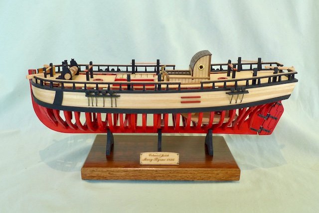
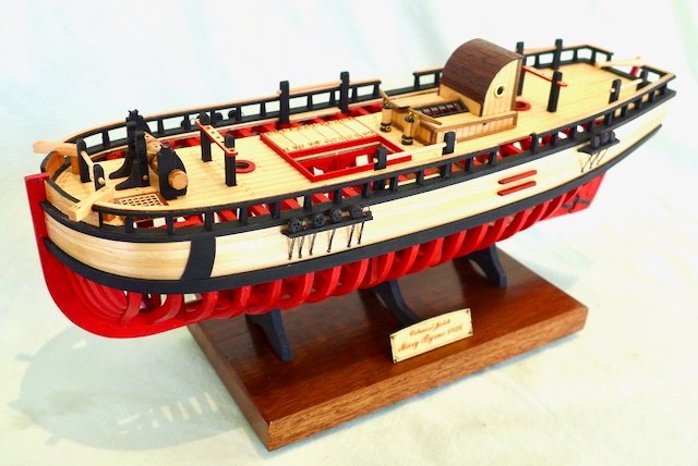
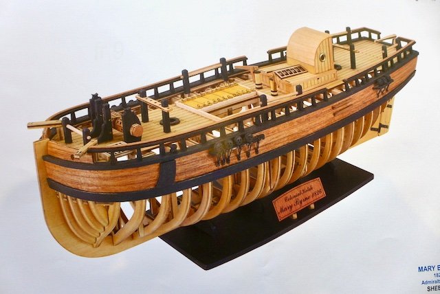
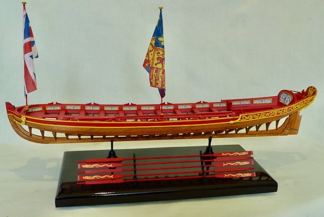
 Have now completed the last stage of fixing steps, channels, deadeyes and straps. The straps are simply made from brass wire as provided after being blackened. All relatively straight forward. That finishes the model. I made a new base to try and enhance the display of the model and a couple of shots of the finished article follow together with the picture of the model as displayed on the kit box for comparison. Picture of model from kit box cover. I have enjoyed making the model but it is disappointing in certain respects as mentioned in my log. However it has suited me as I wanted something to do during our Covid lockdown and it doesn’t have any rigging. My hands have lost the magic touch when it comes to rigging details. The model supplier has given the model a difficulty rating of 4 that surprises me since the full model of the Mary Byrne with full rigging is rated 3. This may put off any one attempting modelling for the first time. However I think it is a suitable kit for a novice modeller as it has the essential ingredients for making a ship model and would be useful as a learning exercise. I don’t think it would be of interest to experienced modellers unless they are in my situation having some time to spare but not as much as a year or two for a larger model.
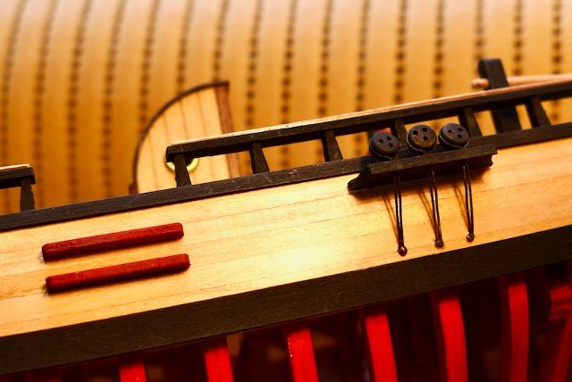
-
BobG reacted to a post in a topic:
Mary Byrne 1826 by rodgerdodger - Modellers Shipyard - Admiralty Model
-
ccoyle reacted to a post in a topic:
Mary Byrne 1826 by rodgerdodger - Modellers Shipyard - Admiralty Model
-
Fernando E reacted to a post in a topic:
Mary Byrne 1826 by rodgerdodger - Modellers Shipyard - Admiralty Model
-
hof00 reacted to a post in a topic:
Mary Byrne 1826 by rodgerdodger - Modellers Shipyard - Admiralty Model
-
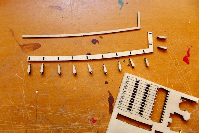
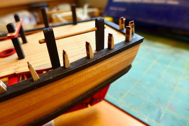
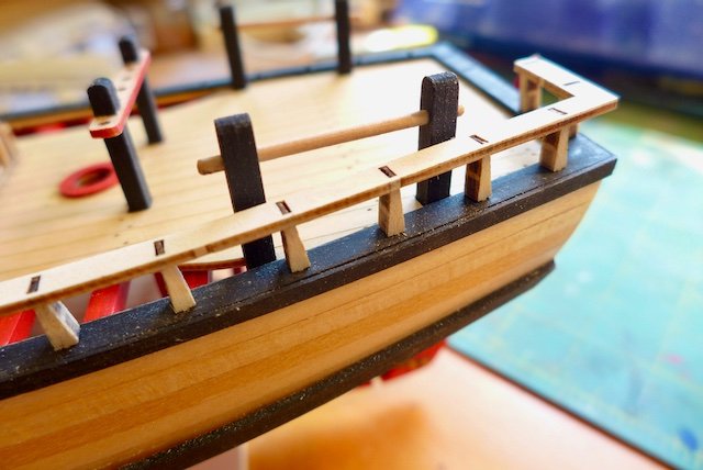
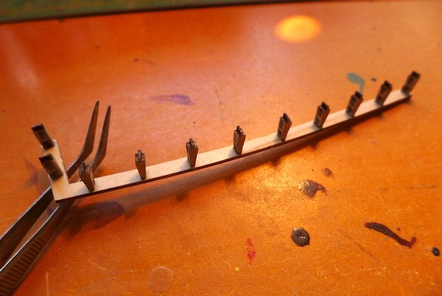
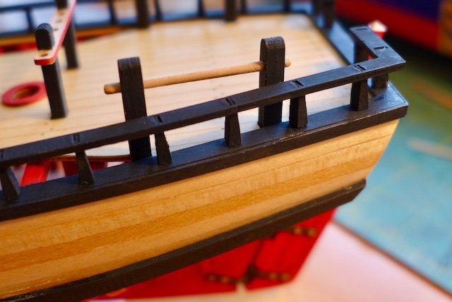
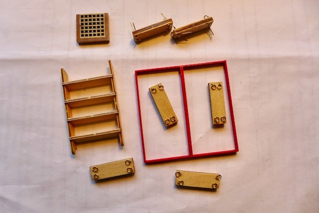
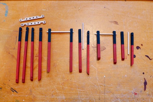
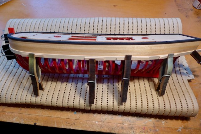
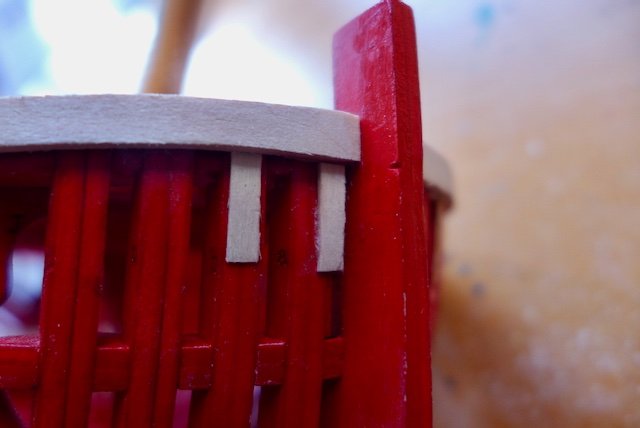
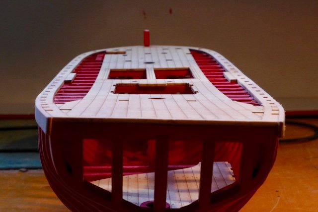
All deck furniture and fittings are now in place. The next task is to complete the fence and cap rails. The fence consists of small fiddly stanchions, a slotted plywood cap rail and a thin cap rail trim that covers the slots in the cap rail. I was concerned that if the stanchions were fixed in place into the slots in the fence base first it could be difficult fixing the cap rail if there was any misalignment of the stanchions. The longest length of cap rail had 13 stanchions to match up. So I decided to insert each stanchion in the fence base, but not glue them. (I should have dusted off the dust before taking this photo!). I then fixed in place the fence rail, juggling each stanchion into place as required. I then glued the stanchions to the top rail by dropping a dollop of CA into each slot in the top rail. I then carefully removed the top rail together with the stanchions and painted the underside of the rail and stanchions. The final step was to glue the assembly back on to the fence base with a dollop of PVA in each slot in the fence base. The PVA gave me time to make any adjustment and pull the plug if there was a disaster. Fortunately it worked! The rail trim has yet to be installed.
-
Gregory reacted to a post in a topic:
Mary Byrne 1826 by rodgerdodger - Modellers Shipyard - Admiralty Model
-
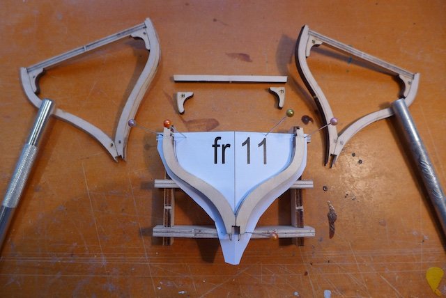
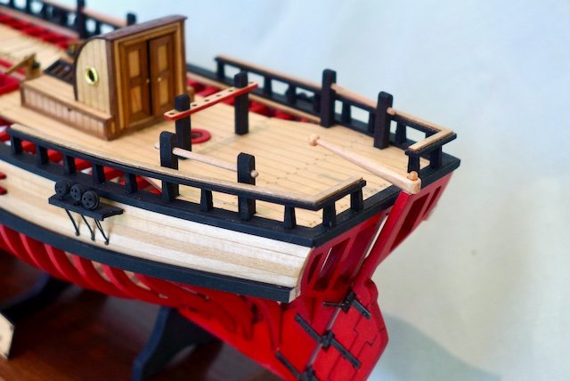
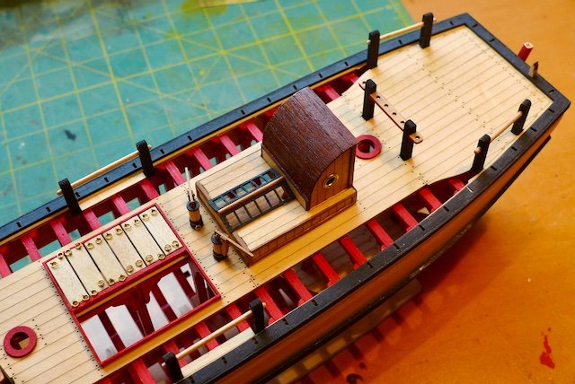
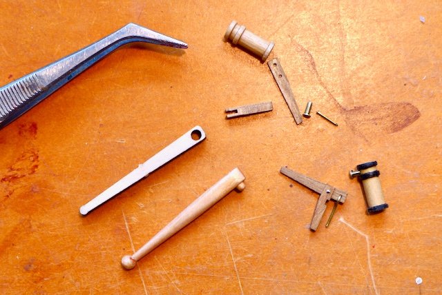
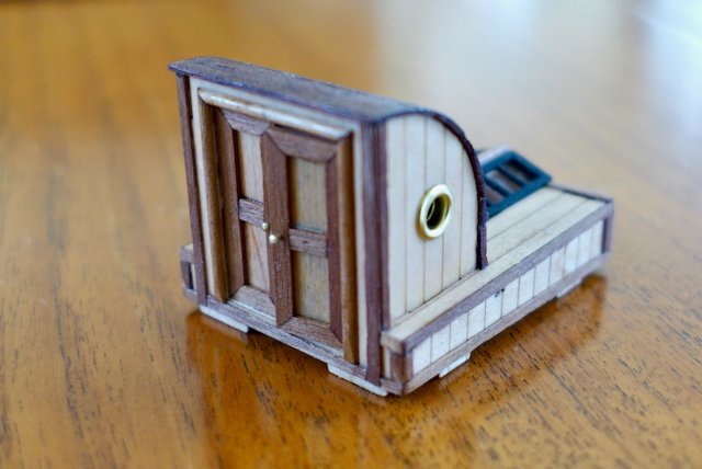
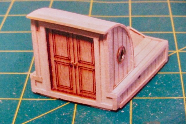
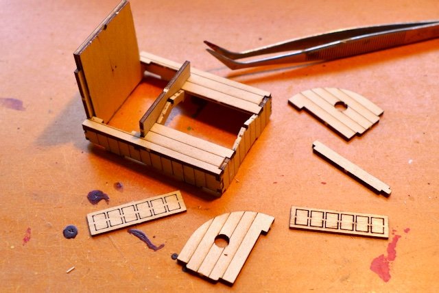
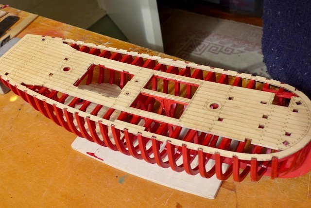
Work progressing on the deck fittings and furniture including the cargo hatch framing and covers, and steps that are between the lower and top deck. Looking at the step dimensions has raised a query in my mind about the scaling of the model. The steps are not seen when installed so haven’t bothered to conceal the plywood edges. Have also finished the fife rail pin bits and pin rail bits. Each bit is located in a pre-cut hole in the deck adjacent to a hull frame face. The end of each bit has to be checked for length and tapered to suit the frame profile at the same time as setting the bit plumb and at the correct height. The frame 11 at the stern of the hull is not vertical having been built at an angle, so the bit at frame 11 had to be cut short at just below the deck with enough contact with the frame to be held in place. The only ‘error’ in the construction details I have come across so far. Two pumps in progress and a tiller I carved from basswood to replace the unattractive plywood tiller provided. The companionway is assembled from laser cut plywood components with etched cladding pattern and doors. The companionway as provided is pretty ordinary and decided to upgrade it with a bit more detail. The companionway as illustrated in the building instructions. The companionway after upgrading with trims etc. The assembled companionway sits comfortably and precisely into the opening provided in the deck. That completes the deck fittings and furniture.
-
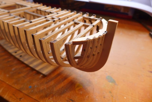
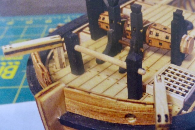
The following is a photo from the instruction manual of the bow area to compare with my last posted photo. You can see why I was keen to disguise the plywood used throughout this model. Not a flattering photo unfortunately and doesn’t help to promote this model.
-
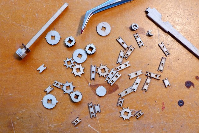
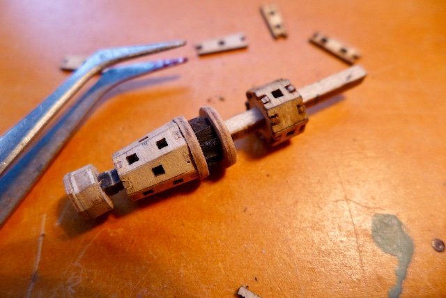
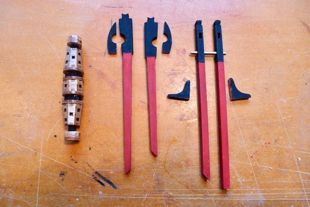
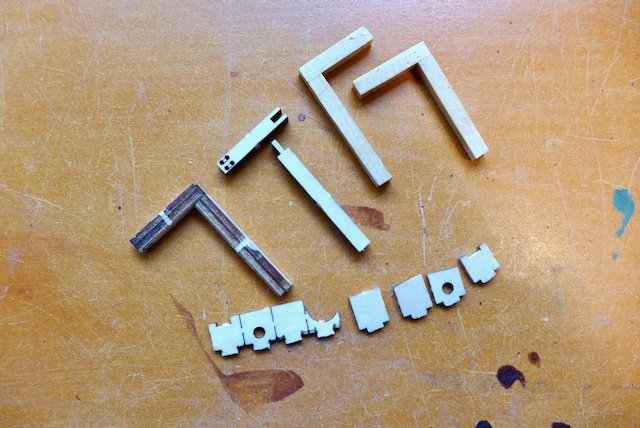
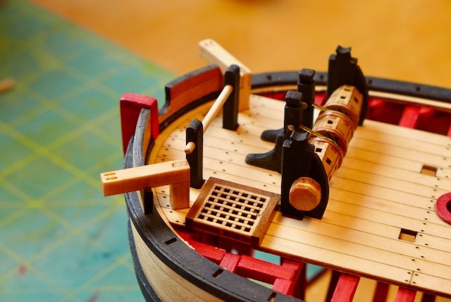
The directions suggest fixing the deck fittings and furniture before the rails, for access reasons no doubt. The first item for attention was the windlass. This is where the 3-dimensional jigsaw concept has been taken to the extreme, clever but very fiddly indeed and a poor result. I considered making an alternative out of a solid piece of timber but decided it wasn’t worth the effort for the moment. The pieces making up the windlass, small, frail and easily broken. Slowly piecing the windlass together. The completed windlass, carrick bit pins and pawl bit pins ready for installation. Having painted the hull frames I was obliged to similarly paint the below deck sections of the pins (and later the fife rails etc.). The completed length of the windlass, governed by the length of the axle, did not match the spacing of the carrick bit pins as set out on the deck, which necessitated widening the deck openings for the pins. At the same time I worked on the Hawses and Catheads. The hawses and made from three pieces that slot into the deck fence base and the planked both sides with thin ply strips. The catheads from the ply looked pretty sad so I made alternative catheads from some spare 5mm sq basswood. A view of the bow after installation of the hawses, catheads and windlass assembly, plus the forward fife rails and a small section of deck grating.
-
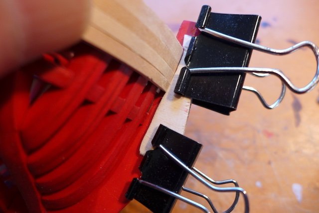
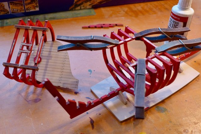
Glad to hear you are continuing with your model. It recently took a month for a new kit to get from Sydney to my address in Melbourne via the mail, due to the Covid restrictions they tell me, so I can only guess how long anything will take to get to your part of the world. The clothes peg looking clamps in the penultimate picture are modelling clamps that conveniently fitted between the frames and were more than adequate for this model, plus some help with fingers and thumbs of course.
-
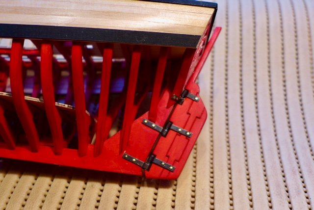
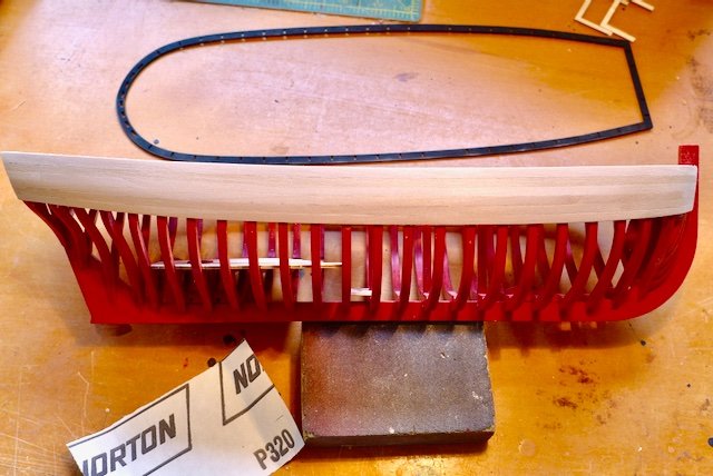
The deck fence edge trim is now completed and the wale is pegged in place after soaking in water. After drying out the wale will be painted black before fixing. The 6mm x 2mm limewood wale took a bit of encouragement to conform to the desired curve and CA was essential when it came to fixing it in place. The instructions suggest fitting the rudder as the final task. But I am glad I decided to fit the rudder before starting on the deck fit-out as it proved a difficult task particularly because of the top hinge arrangement. The hinges are very well made, the best I have come across, but I still managed to break the top hinge trying to bend it to shape. I suspect the designers had a few extra hinges for trial and error before getting the right fit. I will paint out the nails in due course. It is now a good time to do some patch up work on the painting as inevitably there are a few scrapes and scratches from handling the model. I am glad I chose to paint the frames that can be easily touched up as opposed to some alternative finish that would not have been so easy to repair.
-
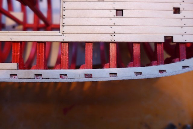
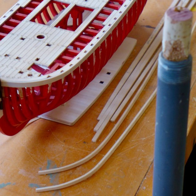
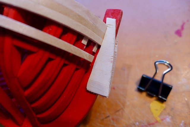
I fitted the first length of hull planking (5mm x 2mm basswood strips) on each side aligned with the top of the deck. The deck overlapped the top of the bow assembly by approx 1mm despite my best endeavours to position everything correctly. Not worth mentioning usually and normally solved by sanding back the excess to match the bow profile. But this was not an option as the following piece that will be placed on top of the deck edge would not fit correctly if sanded back. The solution was to place a couple of shims so that the plank aligned with the edge of the deck. This is a view of the top of the first plank that shows the lodging knees peeping through. I could have spent more time in locating them correctly relative to the frames but this closeup photo exaggerates any misalignment of course. Got a nasty surprise when I checked the hull alignment and found there was a slight twist after fixing the first plank on each side. I am sure I can correct it when I install the next planks but something to look out for. Narrower planks, say 4mm, would make the planking easier and more suitable for this size model. I was surprised that this would occur as I had no problem with the Queen Anne Barge that is a similar open frame model without a deck and lighter frame construction although the build method is very different. This gives me an excuse to show off my version of the excellent model by Syren. Needless to say there is no comparison when it comes to quality of material and components. I followed the well detailed instructions for tapering the planks. There is plenty of advice out there on planking but I will just mention a couple of my ideas on achieving the best result. I prefer to soak each plank in water, place and clamp in position, go walk the dog to allow the plank to dry out, remove the plank and finally fit/trim/bevel if necessary then glue in place. A slow process but makes the final fixing and gluing much easier with fewer clamps required and definitely no nails. To soak the total length of the plank I use an irrigation pipe, plugged one end, stood vertically and filled with water. The cork is to keep the planks immersed in the water and stop them from popping up. A bit over the top for the length of planks on this model but has been useful on previous larger models. Clamping the plank at the bow of a bluff shaped hull is always a problem. My preference is to use a template cut form thin ply profiled to the shape of the bow. Normally I would pin or tack glue this template to the keel but since the keel is painted I used bulldog clips. I have made many a mistake forgetting to fully push in the plank to fit flush with the keel, and leaving a gap. Difficult to fix later. Checking next plank for fit etc. The planking is completed and sanding to shape underway. I did not need to use any filler and the end result is adequate I think to dispense with the second planking with tanganika planks that are provided with the kit. Anyway, I don’t think the finish colour of the tanganika suits this model. Note in the background the next item to be fixed, the deck fence base. Again a flexible, flimsy item easily broken (just once this time while sanding and painting in matt black). The Deck Fence Base fits very precisely onto the deck, and is a large piece to glue and place accurately in position in one go. Firstly I glued the stern edge in place and when set I was able to gently lift the sides one at a time to glue and postion into place.
-
I experienced exactly the same problem and occasionally wondered if I had taken too much off when cleaning the laser burn. It wasn't a problem during the trial assembly as the hatch framings and the braces supplied were adequate to hold the frames together, although at times as you aptly describe you could do with six pairs of hands. However when you start to instal (glue) the frames, i.e. frame 1 it is essential to check it for plumb and alignment and it allow it to set firmly before installing further frames. All the other frames are then installed relative to frame 1 using the hatch framings and temporary braces. Glad to hear you are making a start. I have been diverted from modelling for a moment to house duties now that spring is here and the lawn needs mowing etc.
-
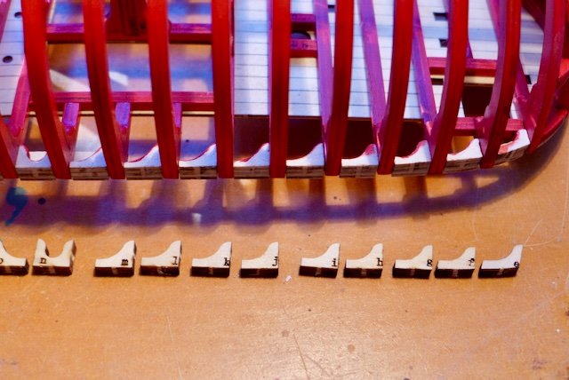
I am now installing the lodging knees to the underside of the port and starboard edges of the deck. A feature new to me. While providing support between the hull frames they also provide a base for placing the first plank to the hull. Very fiddly small pieces and test the patience as it is necessary to remove laser burn and round edges. Having painted the frames I decided I had to paint the knees especially as a part of each knee can be seen when looking down on the deck. The picture shows the port side knees installed ready for final paint. I painted the knees in two steps, before and after installing, for ease of handling. The starboard knees are lined up ready prior to cleaning and painting.
-
I hope you enjoy the model as I have - so far at least. I continue to be impressed how everything fits together very well, like a 3 dimensional puzzle, with some modelling skills required along the way. I look forward to hearing how you might tackle the plywood issue.
-
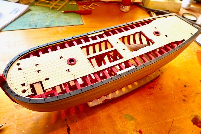
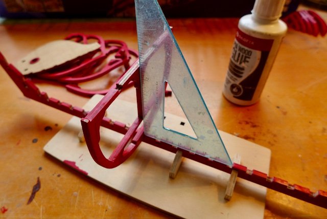
Now the fun starts installing the frames on the keel, starting with frame 1. I had to make sure it was square with the keel as the frame did not sit as tightly on to the keel after removing laser burn. Also it was necessary to check that the frame was plumb by sighting along the keel, and the centre post of frame 1 helped in in this regard. I prepared the lower deck in accordance with the manual, scribing the deck layout on the underside and sealing with matt polyurethane. Contrary to the instructions I installed (but not glued) the four frames supporting the lower deck on the keel to be sure that the frames and deck lined up with frame 1. I trial fitted then glued the lower deck to the four frames and removed the assembly when the glue was set. I followed the instructions and installed frames 2-4, using the companion way beams for alignment. The beams are then removed to install the lower deck assembly but I could not reinstall the beams without cutting them into two sections. I can’t see any way this could have been avoided and it is not mentioned in the instruction manual. While installing the frames and lower deck assembly it was essential to keep checking the alignment of the frames by sighting along the centre line of the deck. The installation of the remaining frame proceeded without any hiccups. When it came to the frames X to D and the main hatch I was able to avoid the problem of installing the hatch beams without having to cut them as for the companion way. The answer is to install frames X and D and glue into place the side beams to assist with alignment. Then instal frame B by weaving it around the side beams followed by the centre beam. Then frames A and C can be installed by weave the frames around the beams. Clear as mud I’m sure! Now for the main deck. I prepared the main deck as per the manual, again scribing the deck layout on the underside, and treating with matt polyurethane. The deck piece in 2mm ply is delicate, especially the outer edge pieces and I managed to break it – twice. I found the edge notches to accommodate the frame were very tight indeed and had to be widened to fit comfortably rather than having to exert too much pressure to make the deck fit, thus risk a breakage. I had a couple of trial runs fitting the deck into position before taking the plunge to glue it. I have been using PVA glue so far on this model to allow a bit of time to get things into final position before the glue sets. It does require a bit of patience to allow one piece to set before moving on to the next.
-
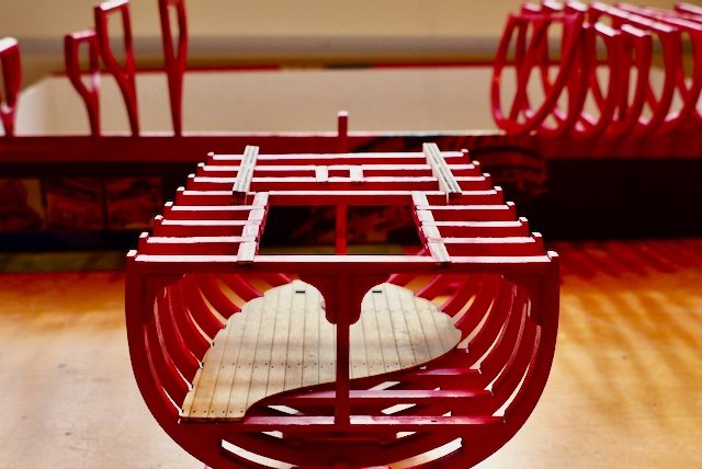
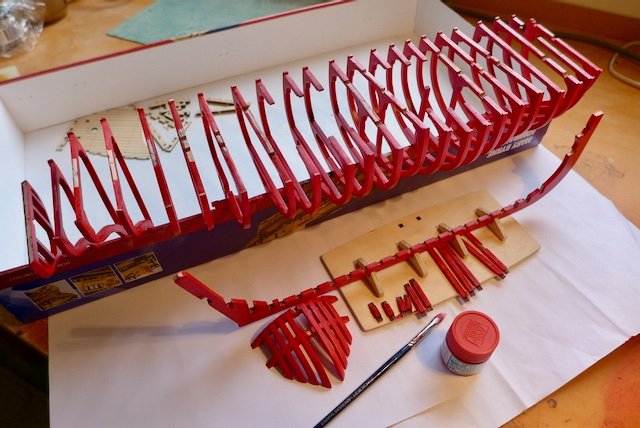
I hope you don’t have to wait too long to receive the model kit, Chief. I see that you are also in lockdown now so will have time to work on the model? Oak might have been the timber used in the actual full size ship but I don’t think they would have used oak in the Admiralty Models but to be honest I don’t know what they would have used. Having decided to paint the frames I had to work out what colour. I tried using a colour similar to a light wood but found the result too artificial and it looked just like painted wood. So I finally decided to be different, go bold and paint the frames red. Hopefully it will be a good contrast with the natural timber look of the deck and the black edge rails etc. It was easy to eliminate any alternative colours such as blue, yellow, green etc. I firstly sealed the frames then applied two coats of modellers acrylic flat red paint. Even then it has not obscured the ply veneers or the etched numbers but it has certainly helped to camouflage them. The edge of the lid of the kit box provided a handy drying rack.
-
I certainly do plan to continue with the build log but I am in the middle of a long pause at the moment, aided and abetted by the Covid lockdown restrictions in Victoria. My idea of camouflaging the ply has come unstuck as the end product was not to my satisfaction. Fortunately I had treated just a couple of frames before I backtracked on the idea. I think I am going to have to paint all the plywood. Taking my time to think it through and make sure I am on the right track.
-
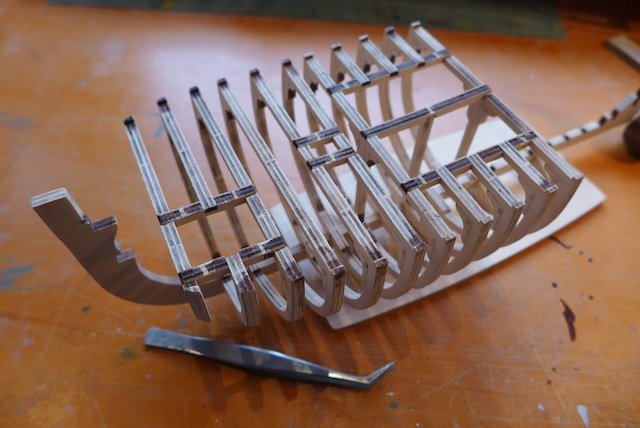
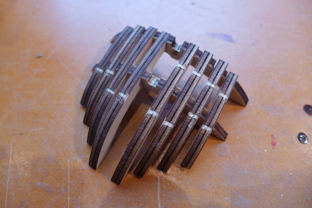
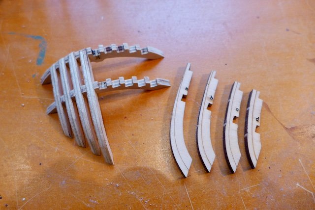
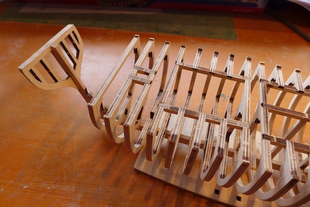
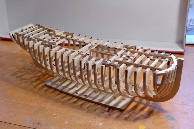
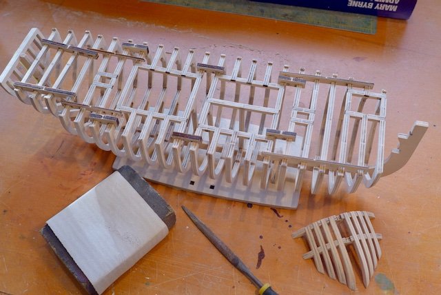
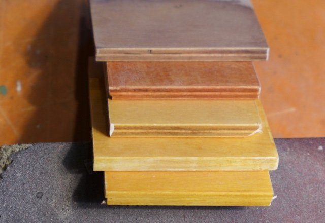
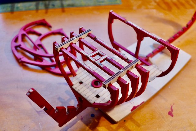
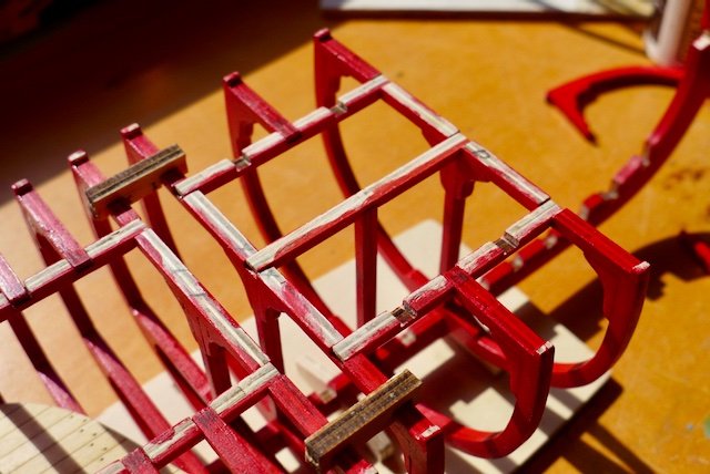
All the fore frames now completed and positioned. Hatch and mast framing installed that helps to keep the frames in place. Note nothing has been glued into place – all dry fitted. Dry assembly of bow block components. Took a bit of pushing and shoving and broke a piece in the process (the first one). Note fairing lines again. Assembly placed on bow in final location but not glued. There appears to be an out of level alignment between bow assembly and the connecting frame that will have to tackled later. Now installing frames aft of centre frame together with further hatch framing that helps to hold everything together and in place for the time being. This is an interesting feature that you don’t see on typical plank on frame models. The final three frames, as the hull tapers to the stern transom, are not made in a flat plane, but are angled. A jig is provided with templates of each frame to assist with this task and to get the angle correct. I discovered that the templates are not exactly to size and it was important to check the gap to take the top deck beam before gluing the joint. Have reached the stage where all frames are now made and installed. Have also installed the temporary braces between the frames that hold everything in the correct position and help to check deck alignment etc. The project so far has been similar to a 3-dimensional jigsaw puzzle getting the numbered pieces in the right position with some modelling work here and there. Very well engineered and every part fits snugly. I now have to dismantle the whole lot for final cleaning and sanding. Took a couple of hours to clean all components of laser burn and final sand. For the moment keeping frames assembled on keel for convenience. No matter how much I sanded the frames (the plywood is made of soft wood and sands easily so you can overdo it not careful) it was not possible to eliminate the laser burns evident in the edges. So the problem of solving the appearance of the ply frames etc. has to be addressed. I selected a piece of excess ply left from the laser cut boards. I sealed the ply including the edge with sealer (Feast Watson that I had from another project) and applied stains that I happened to have in the cupboard. The top layer is Wedge, the second Jarrah and the third Baltic Pine. It is obvious that regardless of the colour the stain does not conceal the ply layers. It requires an opaque layer such as paint before applying the stain. For the 4th layer I applied a coating of white acrylic gloss hobby paint to the edge. I didn’t notice it was gloss until later so I used white acrylic flat hobby paint for the 5th layer. Not perfect but a much better result than leaving the edges as is. I like the Baltic Pine colour but I don’t know if it is appropriate for this type of model. However, the big question is do I really want to take the time to seal every component, paint the edges (inner and outer) with paint and finally stain them? Time to pause and take a break.