Hubac's Historian
-
Posts
2,941 -
Joined
-
Last visited
Content Type
Profiles
Forums
Gallery
Events
Everything posted by Hubac's Historian
-
 All beautifully coped together.
 -
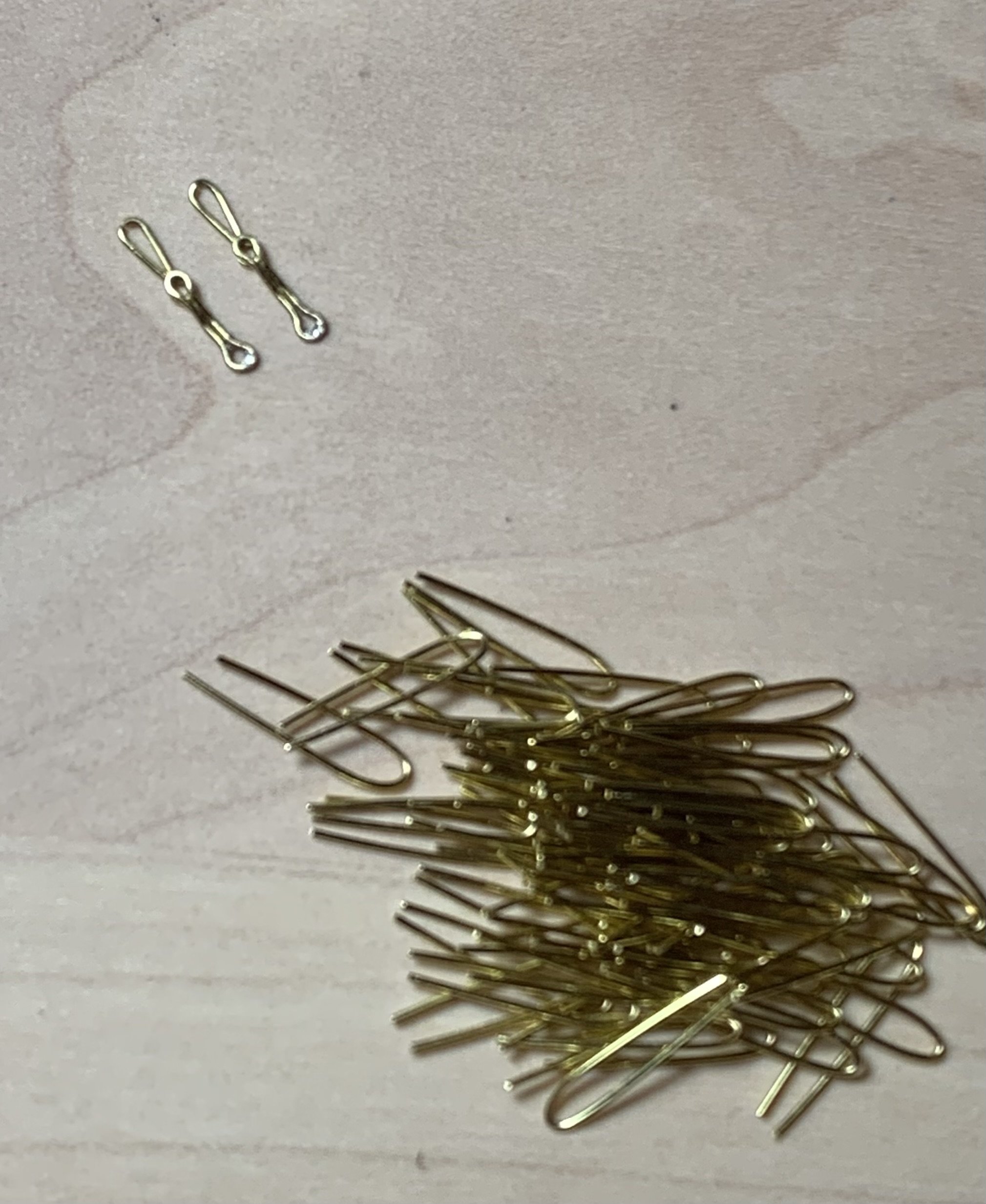
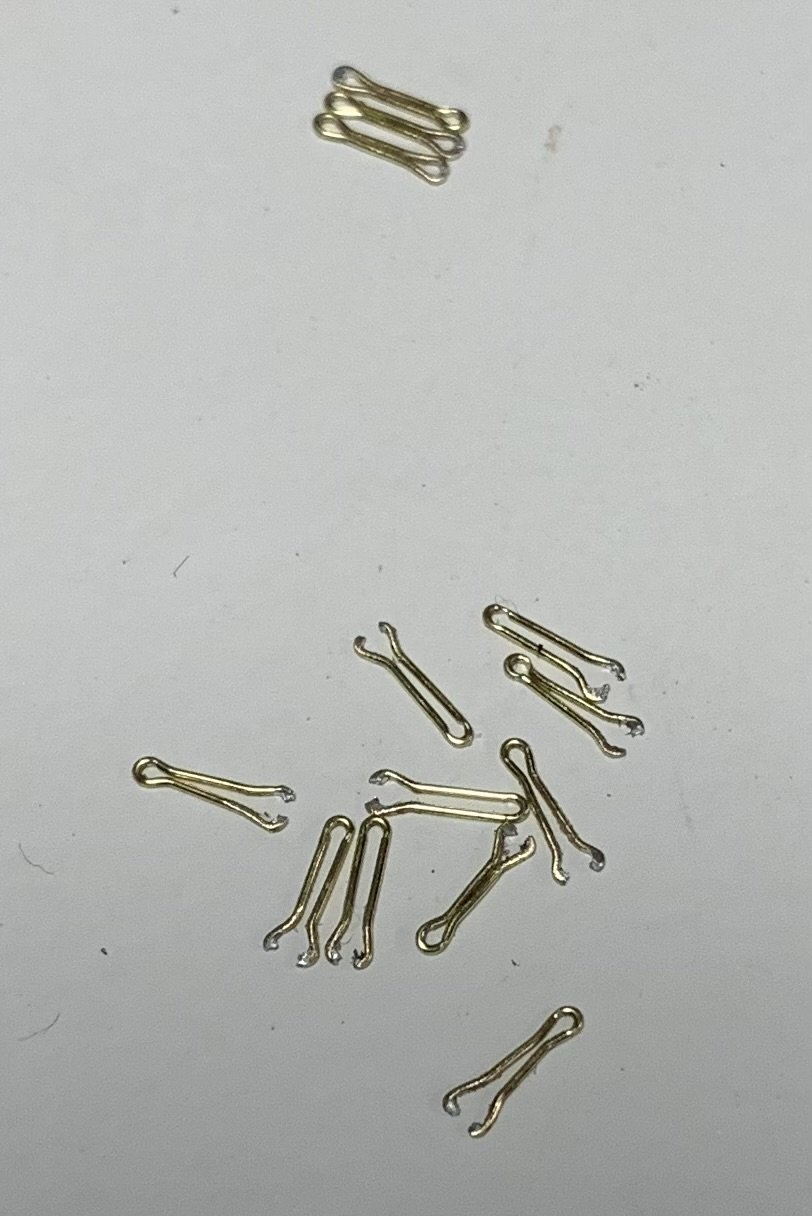
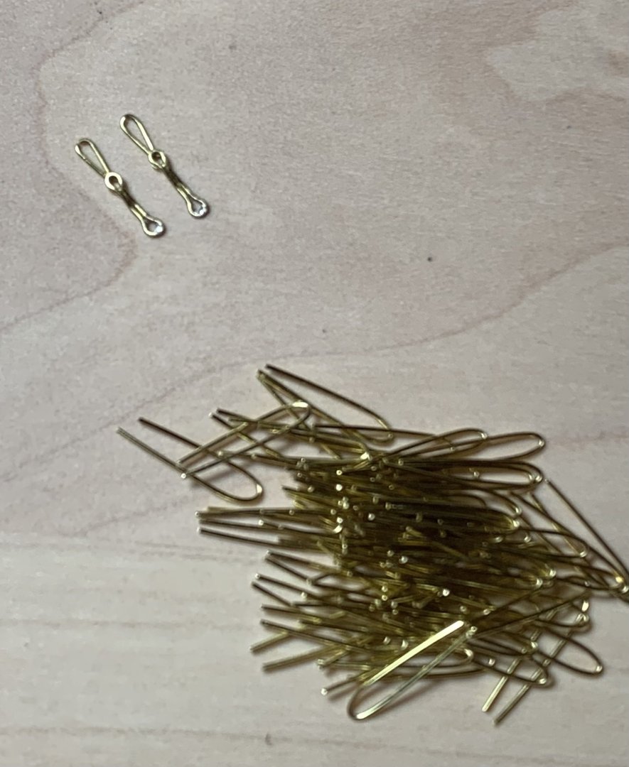
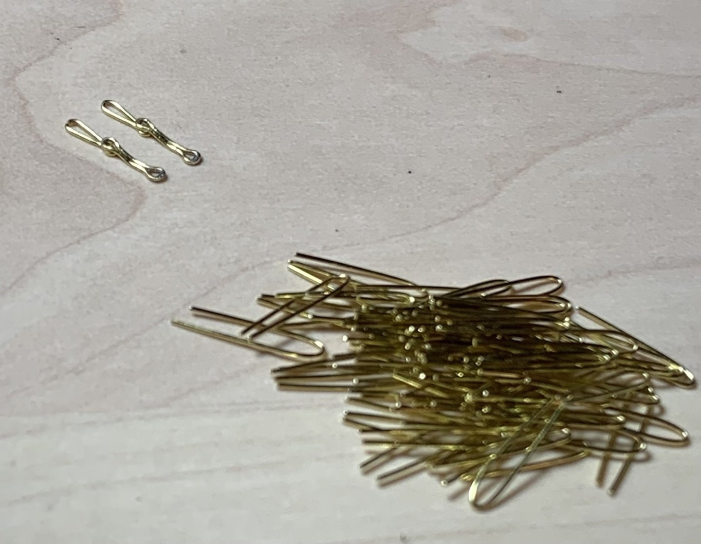
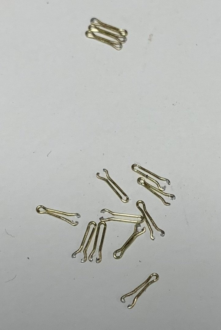
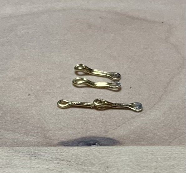
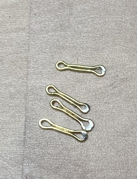
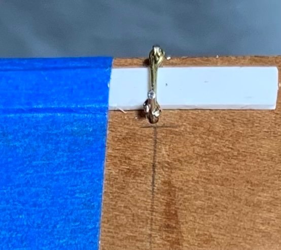
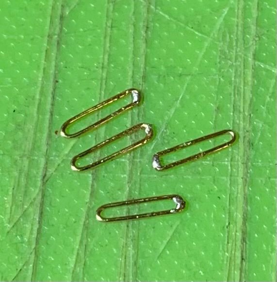
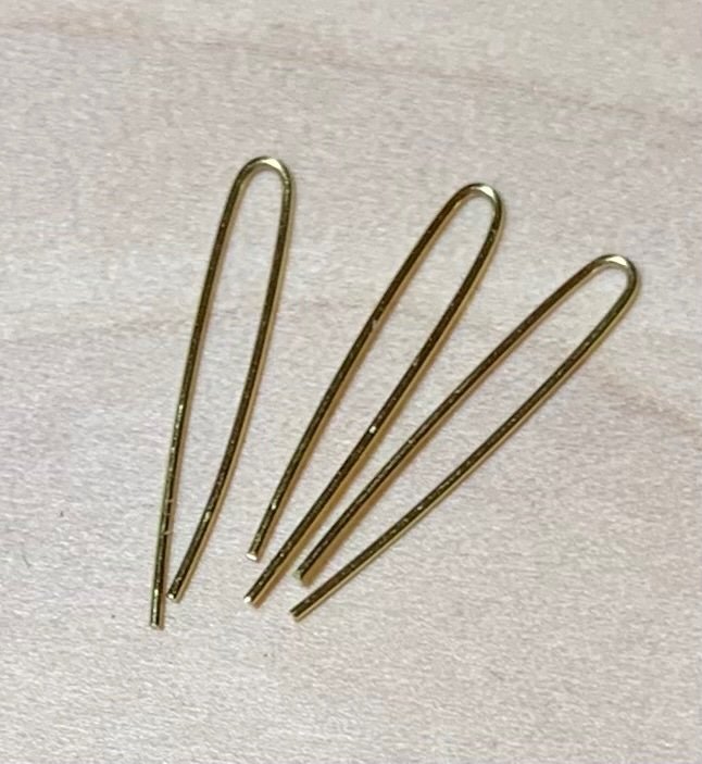
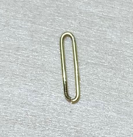
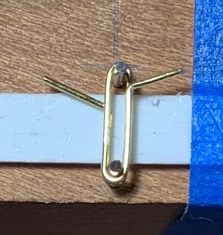
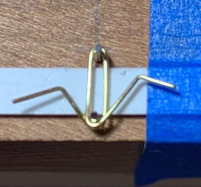
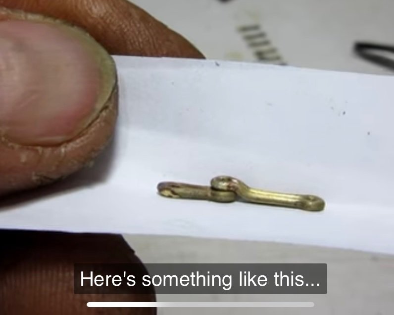
I can’t escape the fact that I continue to fail at this chain-making exercise. As the old maxim goes, though, every failure is one step closer to success. I’ve now thrown away two whole batches of chain preventer plates. While I was quite right to follow Andre Kudin’s example, for the process of their manufacture, I eventually discovered that that process is not entirely transferable from 1:48 to 1:96 scale. After forming his basic links, Andre solders them closed at one end, and then places the closed link back onto the two pins so that he can crimp an eye on each end with his round pliers. Well, the 28 gauge brass wire I’m using does not provide enough surface area for a strong enough bond to survive the crimping. My success to failure ratio was pretty poor: So, my lesson from that exercise was that I needed to do the crimping before soldering one end closed: These soldered loops will be the lowest end of the chains, bolted into the wales. That way, I could induce a series of bends into the upper half of each preventer plate, so that they could overlay the next small link: Above I’m just using another preventer plate to check that the bends I’m making are sufficient. So, I spent a good chunk of time cleaning up the solder and inducing bends into the remainder of the preventer plates. The solder joint will be re-enforced with the CA glue that fixes the pin-bolt in place: With that out of the way, I could make a new, slightly closer-spaced pin jig for the next small link, which is only crimped on one end, where it seats beneath the preventer plate. Now that I have a process that I know will work, and now that I’ve had all of this practice, these next links should go fairly quickly: I have a lot of these to make, solder and bend - about 70 to ensure I can use the best. This has all been a colossal PITA, but it was really important to me that all of this look very clean and uniformly shaped. In the process, I have acquired some very valuable metal skills that will only enhance this and future projects. That said, I am going to experiment with using black nylon thread of an appropriate diameter to connect the deadeye strop loops to the small links. This would essentially be a variation on the way that the stock kit represents these links, but I will do individual chain loops that draw tight with some form of slip-knot that I can pull up and hide behind the deadeye strop. Andre had a great method for producing these variances, but it is all just that much more tedious in the smaller scale. The advantages of doing this are several. So long as there is not a jarring difference in appearance between the black thread and the blackened metal, it will save me tremendous amounts of time. It also simplifies the difficulty of accurately measuring and keeping track of a series of increasingly longer links as the shroud angle increases from fore to aft. Lastly, it greatly simplifies the placement of the deadeyes because I can add the retaining strip, in advance, and it also makes it much easier to locate and properly secure the bottom two links. Hopefully, that will work out. Well, I keep saying that I’m going to get back in the swing of the project, and then I get sucked into coaching another basketball team - now my son’s Spring rec team. Meanwhile, the Rangers and Knicks are just too compelling to ignore this post-season. At least for now, I can see the end of the tunnel for these chains, which is tremendously motivating, and then I can return to the more immediately gratifying work of outfitting and arming the main deck. Thank you all for taking the time to look back in on This Old Build. More to come!

- 2,437 replies
-
- 10
-

-
- heller
- soleil royal
- (and 9 more)
-
Another brilliant subject, Tomek. I love the clean and simple lines.
-
This all looks great Eric. I like your aft increase in wale sheer. I’m debating whether it makes sense to have a corresponding increase in the middle band of wales, as the sheer would have run parallel. The upper main wales - at the juncture of the upper bulwarks are pretty fixed, although one could add to to top edge of the upper most wale and feather it back. It mY not really be worth all of that extra effort, though.
- 94 replies
-
- 2
-
-
- Ship of the line
- Heller
- (and 2 more)
-
Beautiful carving and a fascinating display!
-
Lighter wash was the way to go!
-
Or, can you simply wash back the grey a but with a little solvent? Always test in a little scrap decking, or the underside of the actual decking, if it’s not already glued in.
-
Are you considering balsa fillers for the lower (below waterline) portion of the bulkheads? As you say, she has a very bluff bow and the bulkhead spacing is a little sparse. Fillers would make the under-layer of planking much easier to fair and secure.
-
This all looks fantastic Bill - nice and clean! You did an excellent job of fairing the sheerline.
-
Ian, you continue to amaze with this build! I was just talking it up to my club, last night, so you may soon have a few new on-lookers. The bulwark sweep, previously, did not jump out at me as problematic, but after modification I can see what an improvement in practicality and aesthetics you have made. Well done!
- 502 replies
-
- 4
-
-

-
- Quadrireme
- radio
- (and 1 more)
-
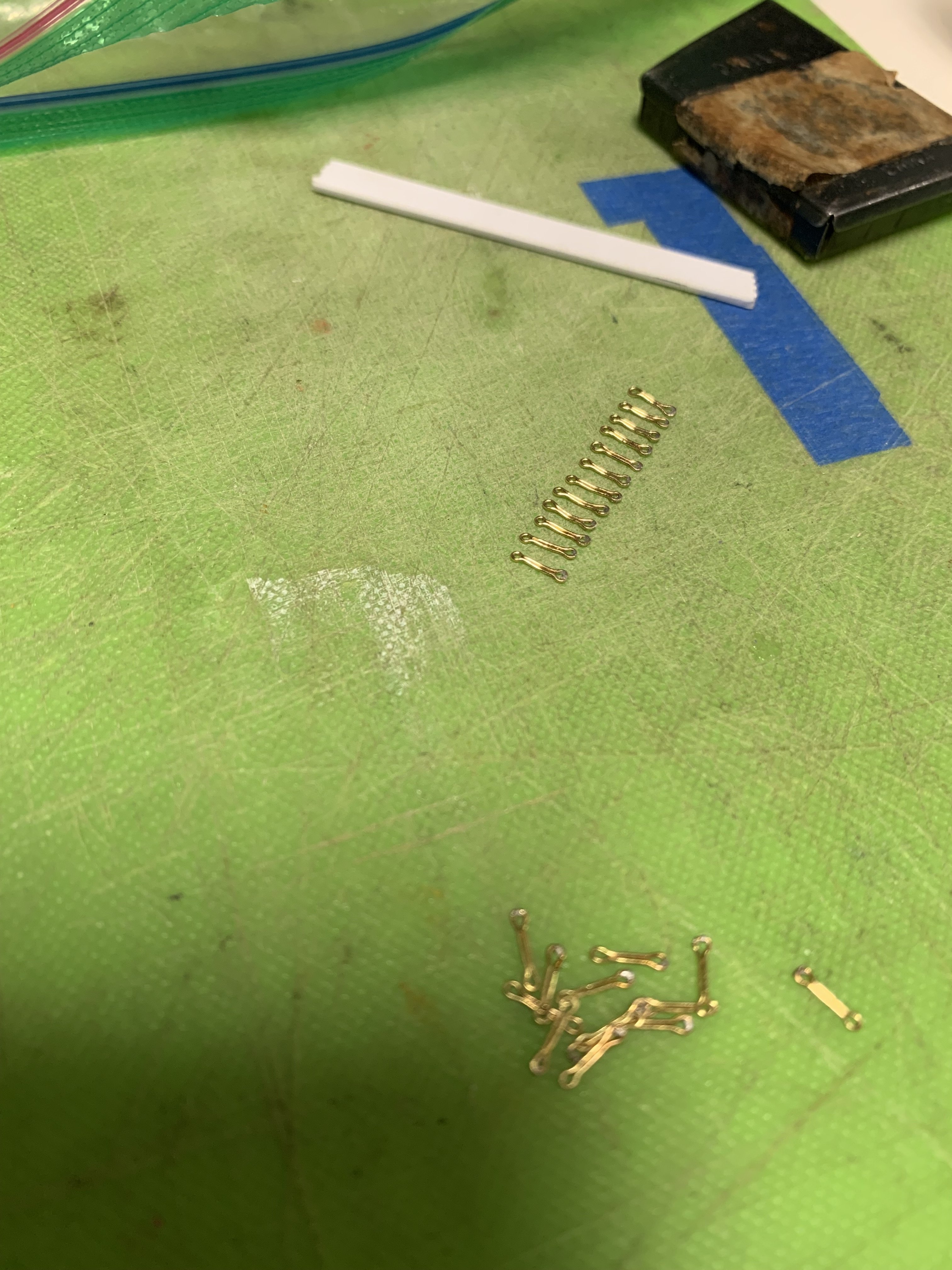
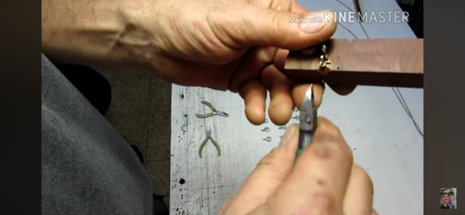
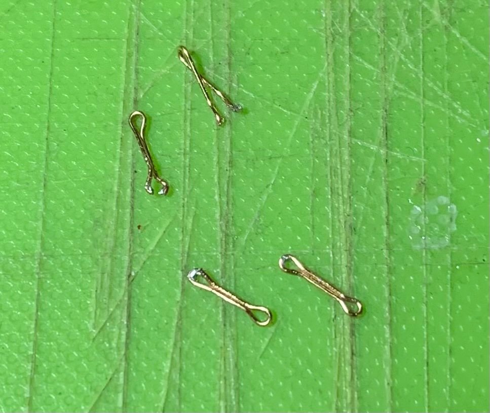
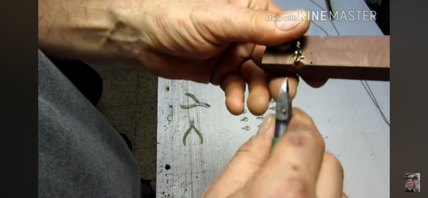
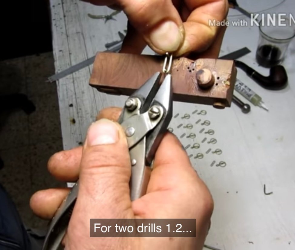
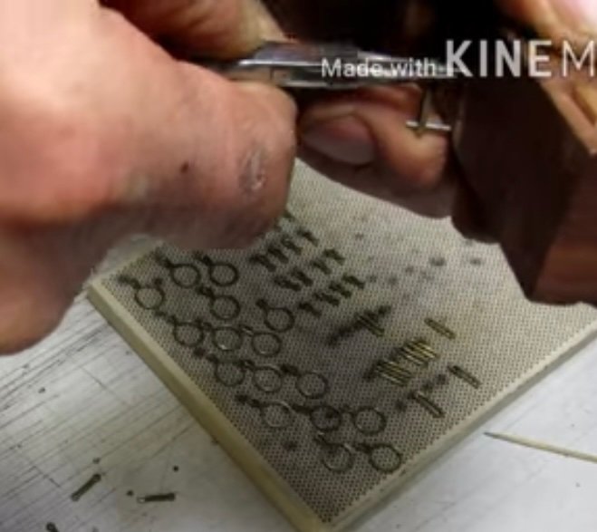
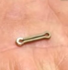
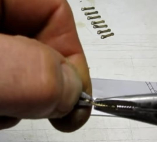
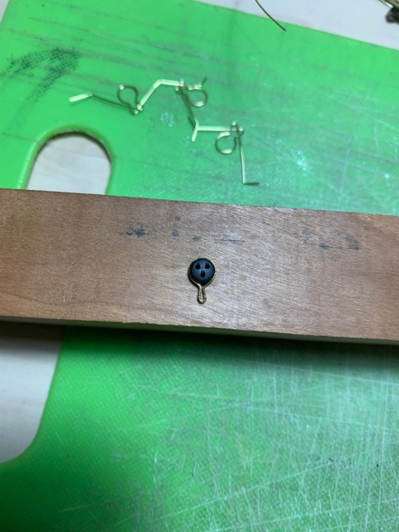
Well, the 6th grade CYO basketball season has drawn to a close and our team succeeded beyond my wildest dreams: we went 13-1, and captured the Manhattan division title. Our second and final loss came in a division matchup with the Bronx winners. We played a gritty first half, and kept it close, but made mistakes in the second half. We were simply overmatched. Nonetheless, it was a wonderful and extremely rewarding season. The Knicks, on the other hand, continue to surprise, so my attentions remain somewhat divided. That being said, I am lately looking to focus more on model building. I’ve completed all of the fore, main and mizzen channel deadeye strops. Although Andre Kudin’s particular method is definitely more efficient with less clean-up - he solders the lower strop loop at a neatly cut joint - I stuck with the R.C. Anderson overlap method I had been using because the strops were coming out uniformly, nicely shaped, and strong. I will change my approach for the deadeye strops in the tops. Next in order to be made are the chain preventer plates. One of the key differences between what I had first tried, when making the chain preventer plates, and what Andre does is that Andre bends each plate from an individual length of wire, rather than try to economize on material by wrapping a longer length of wire, many turns, around an appropriately sized former. When you do the latter, for one thing - you may succeed in crimping the continuous loop neatly around the former, but it is nigh impossible, after parting the links to get the links off the former without pulling them all out of shape. The other issue with parting the links in this way is that you end up with one neat flush end and a pinched end, which leads to a weaker solder joint. What I am after are uniformly straight chain links, free of odd kinks, and sloppy joints. To that end I set up a simple bending jig like the one I see in Andre’s videos. Following is a series of screen captures from his YouTube videos. This particular video is either #13 or #16, in the series, if I remember correctly: And following along, I first pre-bend short lengths of wire around a drill mandrel: I’ve placed a shallow spacer beneath the link area, so that the ends will be slightly raised and easier to crimp with my parallel pliers: I crimp snug around the upper pin, then use my pliers to pull each end snugly around the lower pin. I then crimp around the lower pin: I can then remove the link, and flush-cut each side of the link. A little tweezer/finger manipulation creates a nicely closed link: Silver solder paste has proven to be really great as I can control its application with the tip of an Exacto. A touch to the iron, and I have nicely soldered joints that only require a little cleanup: Now, Andre puts the soldered loops back over the two-pin jig and uses his round-nose pliers to crimp eyes at each end. I found, though, that the joints with this 28 gauge wire simply failed when I tried this: Alternatively, I found that I could place each link end over the lower pin, hold the outer end with a tweezer, and use my round nose plier to crimp around the single pin. This worked beautifully: Now, It’s a simple matter of doing that over and again about 60X. It is, of course tedious, but satisfying to achieve the result I am after. More to follow! Best, Marc
- 2,437 replies
-
- 16
-
-
- heller
- soleil royal
- (and 9 more)
-
Just awesome, Bill. A beautiful display!
-
It’s funny - I was wondering at the necessity for the card re-enforcements, but then I got a better sense of the scale with your arm in one of the previous shots. This is a fairly large hull. As always - great progress, Gary. Hull looks sweet!
-
I echo the sentiments of all above - simply extraordinary!
- 397 replies
-
- 3
-
-
-
- cutty sark
- revell
- (and 2 more)
-
Peter, you must be in the midst of the middle phase of your working life, when it is most demanding on your time. Well, fear not - we will wait for you, when you are ready. This build is too good to simply forget about. Best, Marc
- 30 replies
-
- 1
-
-
- Corel
- wappen von hamburg
- (and 1 more)
-
BTW, Bill, you really are a master of weathered deck effects. Looks great!
-
Well, when simulating a deck with underlying framing, you have to first determine the likely spacing of the beams. The hatchways are always a useful starting point for figuring this out. Once you have a reasonable layout - and I don’t think this necessarily has to exactly match that of the Endeavor replica, it just has to be plausible and regular - you can then figure out, at scale, where planks land on beams within the 25-30’ range. This is one of those things where, since you’re not making a rigorous, fully framed and exact copy of the original ship, there is some latitude, IMO, in executing the details. The goal is an improvement over stock, and that the execution not be jarringly wrong. Of course, the Endeavor is an example of a type of ship called a “Whitby Cat.” If you did want to produce a fully authentic deck layout, I don’t imagine you would have too much difficulty finding original construction drafts that would show the deck framing. It’s really up to you, as to how far you want to take it.
-
I hadn’t realized how far behind I’d fallen on your build, Michael. She truly is the “Golden Devil,” now! Really beautiful paint work and filling-in of the missing ornamentals.
-
Yeah, I agree that alternating butts are fine on the lower deck, but a 3 or 4 butt shift looks much better on the main deck.
-
Many congratulations, Bill, on completing this magnificent model. I have always thought this model looks best on its waterline, and the diorama you have created shows her to best advantage. I look forward to watching your Endeavor take shape!