Beckmann
-
Posts
344 -
Joined
-
Last visited
Content Type
Profiles
Forums
Gallery
Events
Everything posted by Beckmann
-
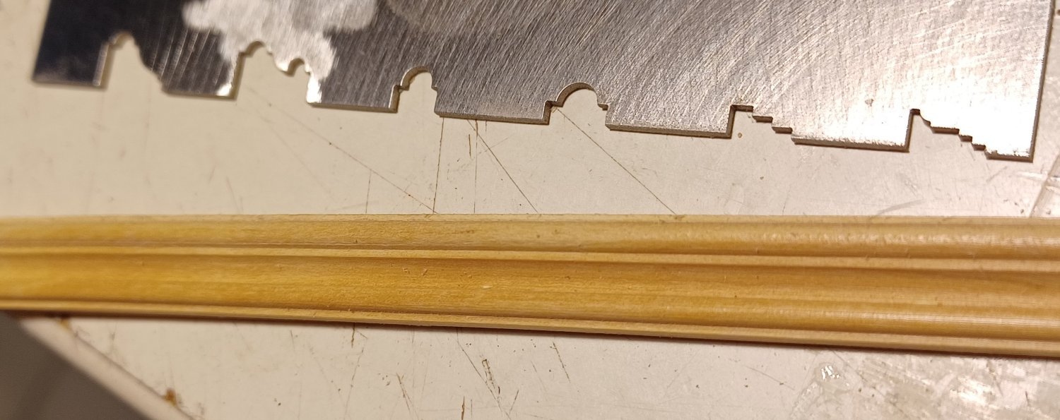
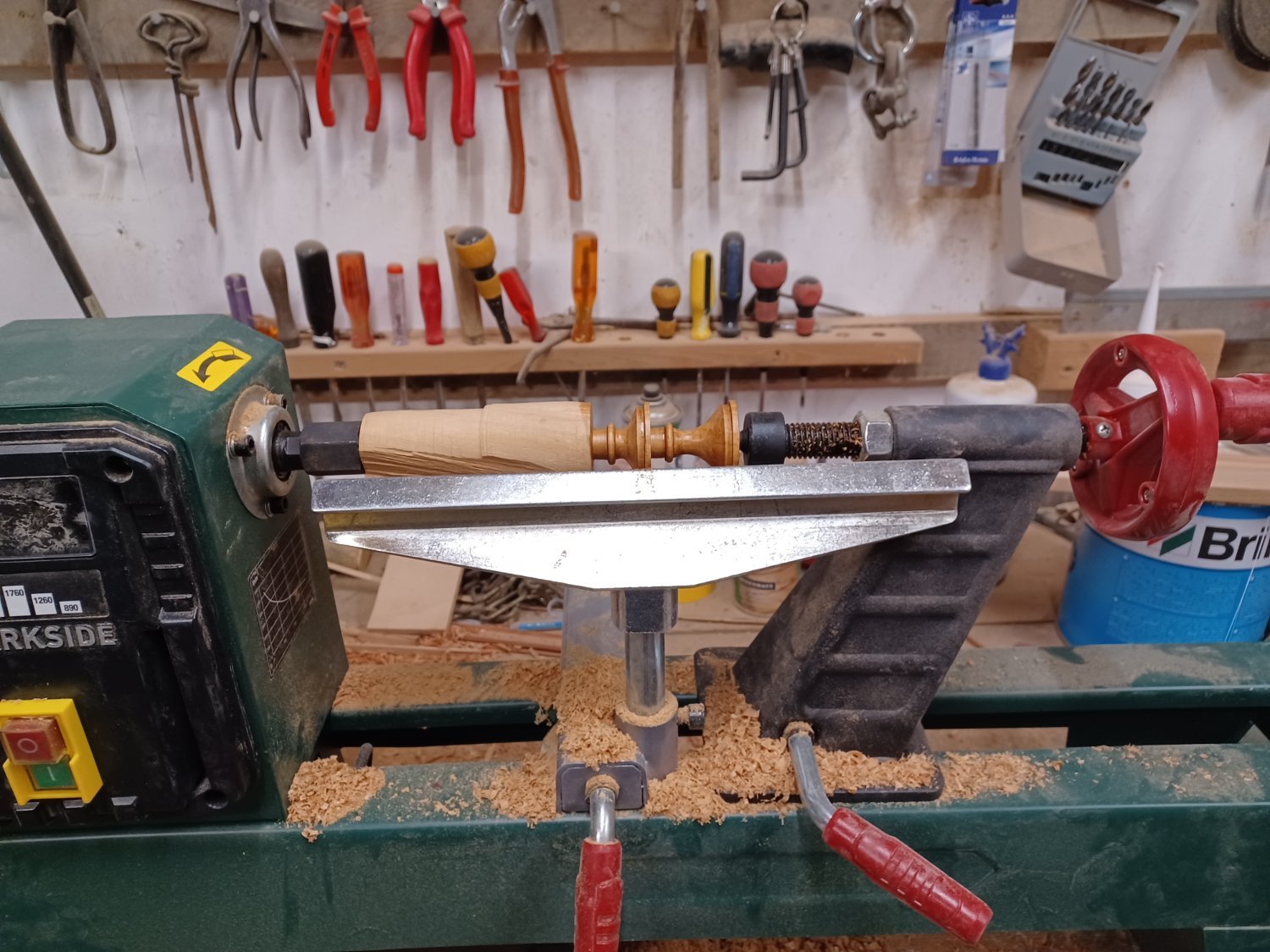
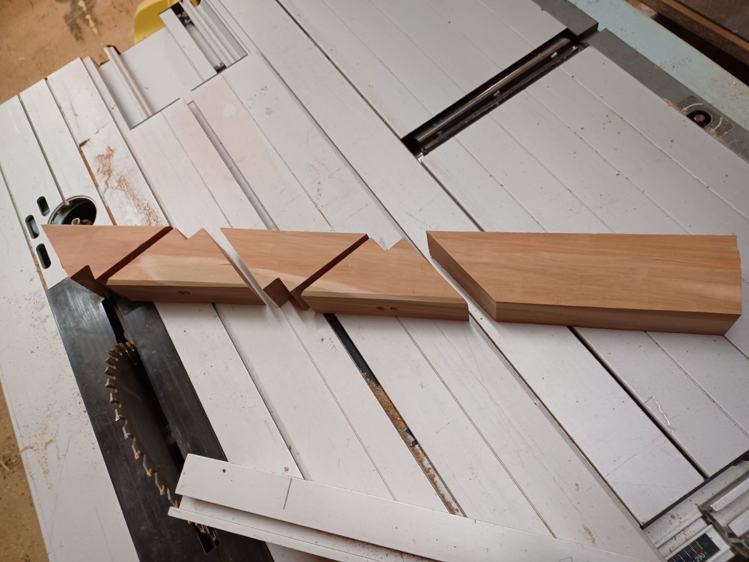
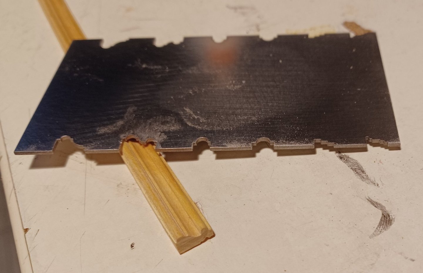
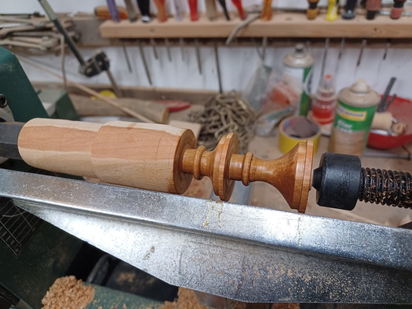
 Hello everyone, Just a small note today, perhaps the information will be helpful for some of you. The fancy moldings of the TRE KRONER are an important element, so I have been looking around to see if it is possible to get an ornamental scraper wich is more precise than I can achieve by hand with a file and saw. After several inquiries, I ended up at the company MetallEhrnsberger in Teublitz/Germany, which also accepts such small private orders. I had to send them a CAD drawing of the desired profiles and of course select a material for the scraper, that was all I needed. I chosed 1 mm thick steel, the costs were €40 altogehter. I am very happy with the result. I couldn't have made the scraper that nice. The material thickness of 1 mm also makes it possible to sharpen the burr several times if it gets a bit round. I used boxwood as the material for the strips. I had sawn up a supply of it some time ago and left it to dry. Matthias
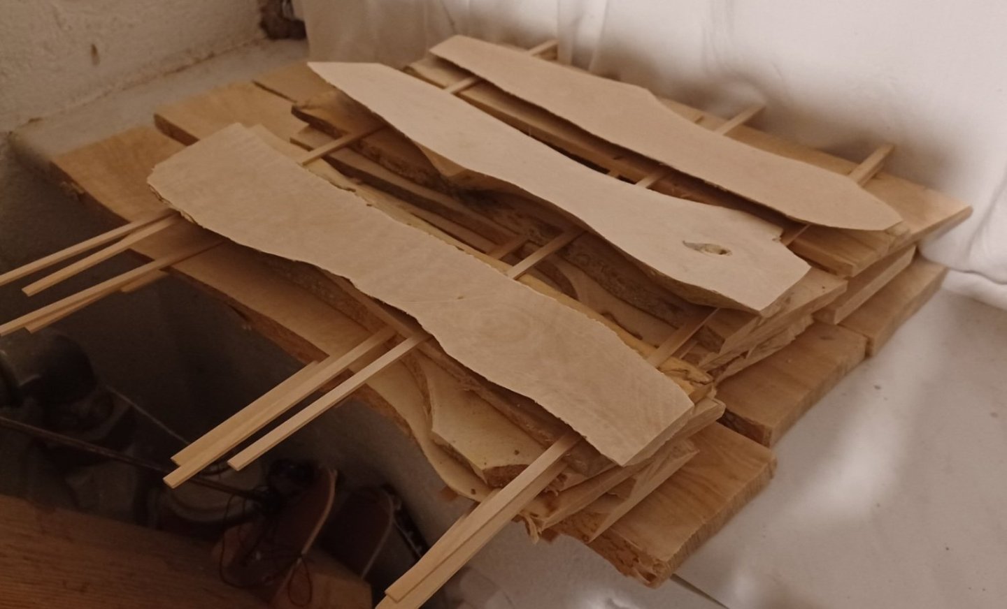

-
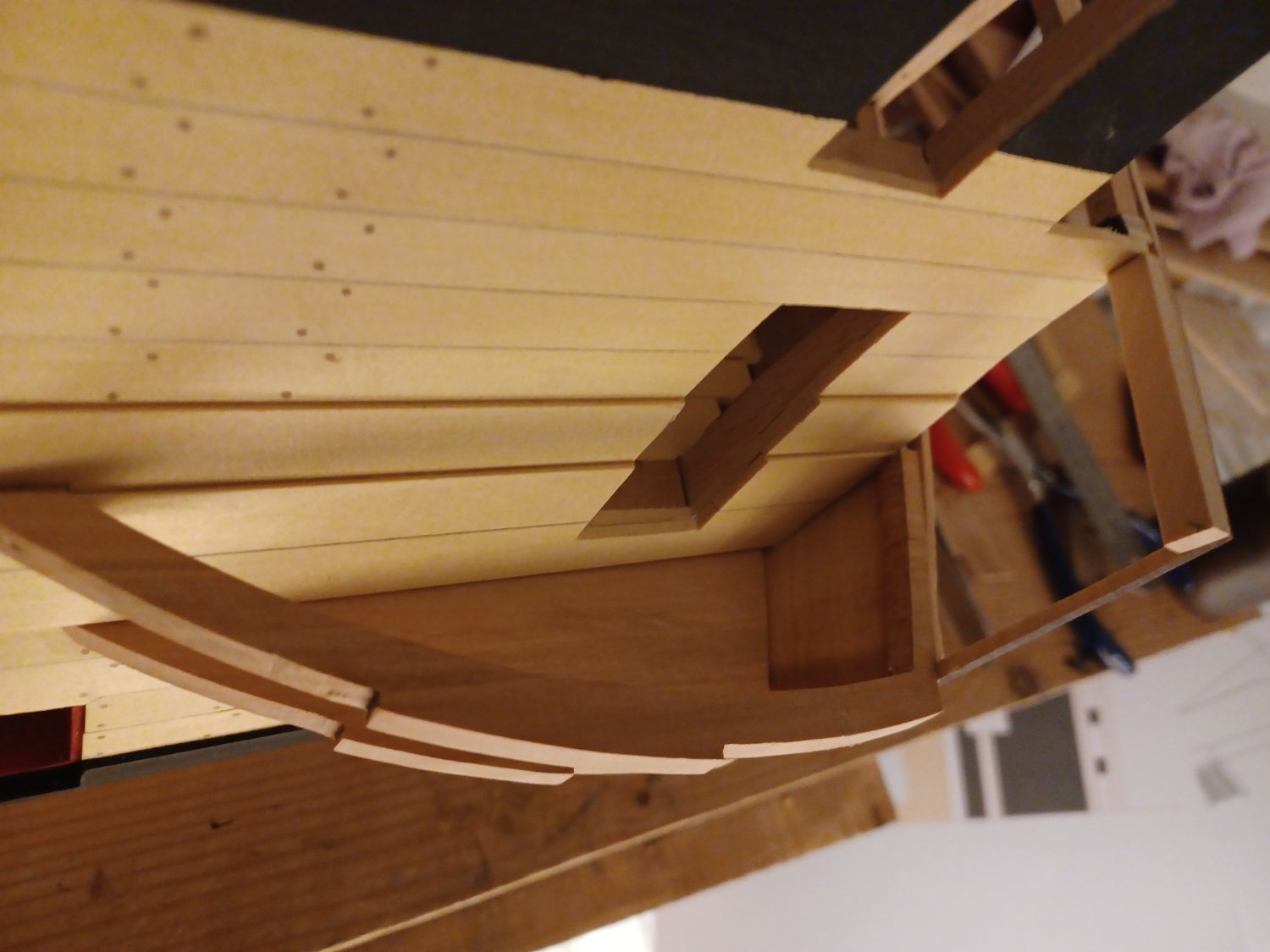
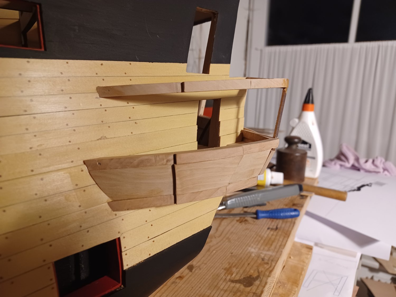
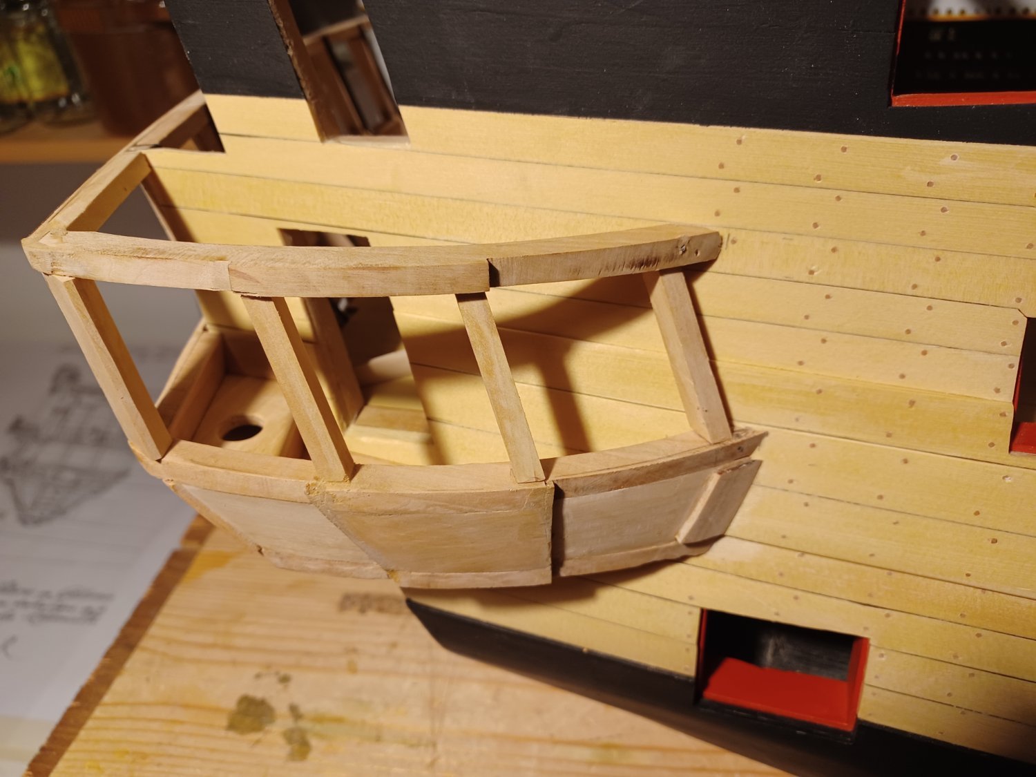
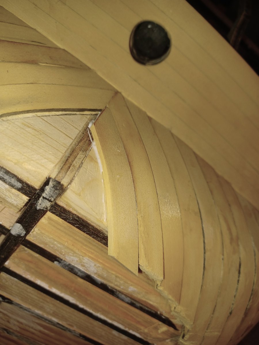
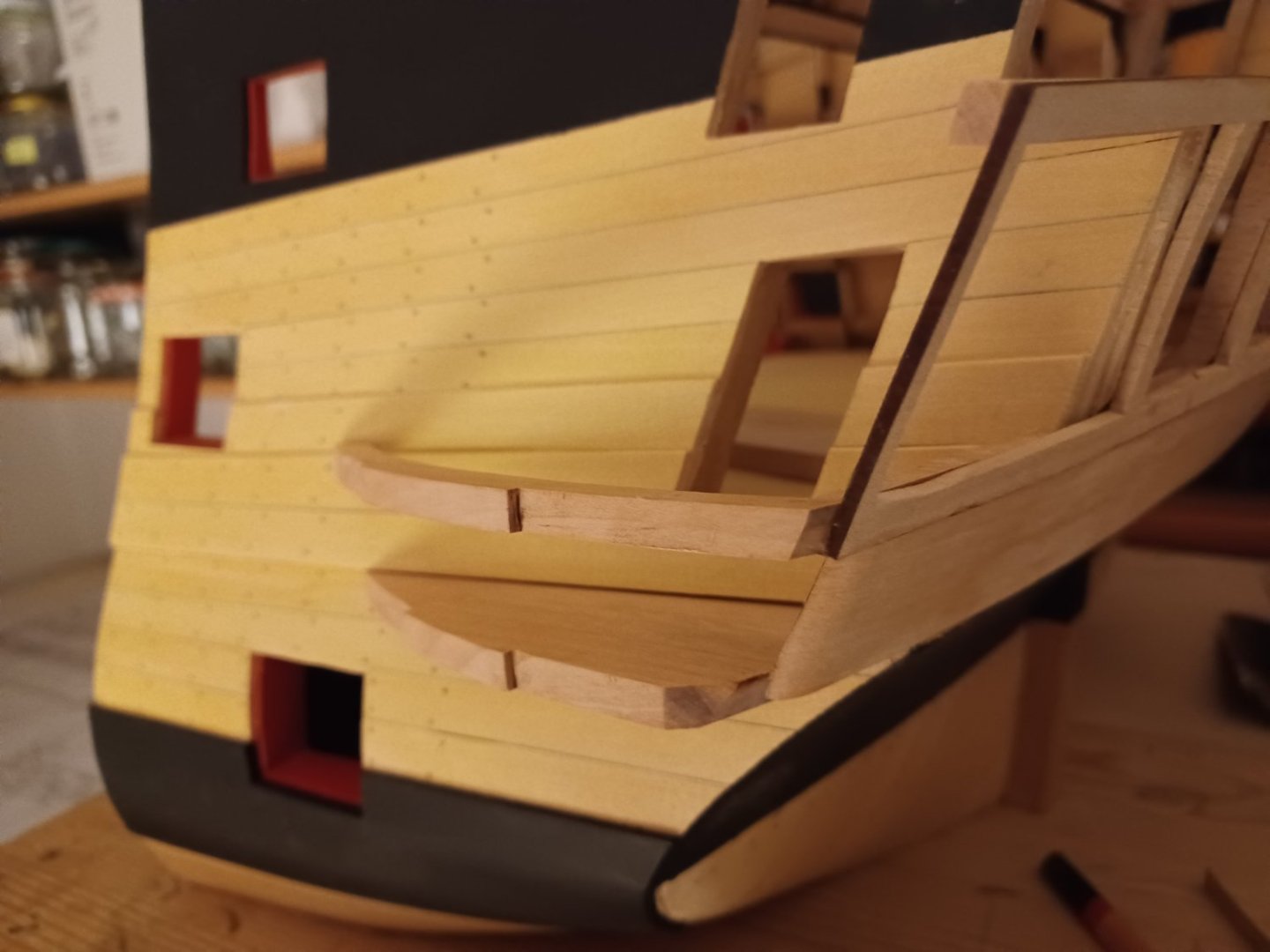
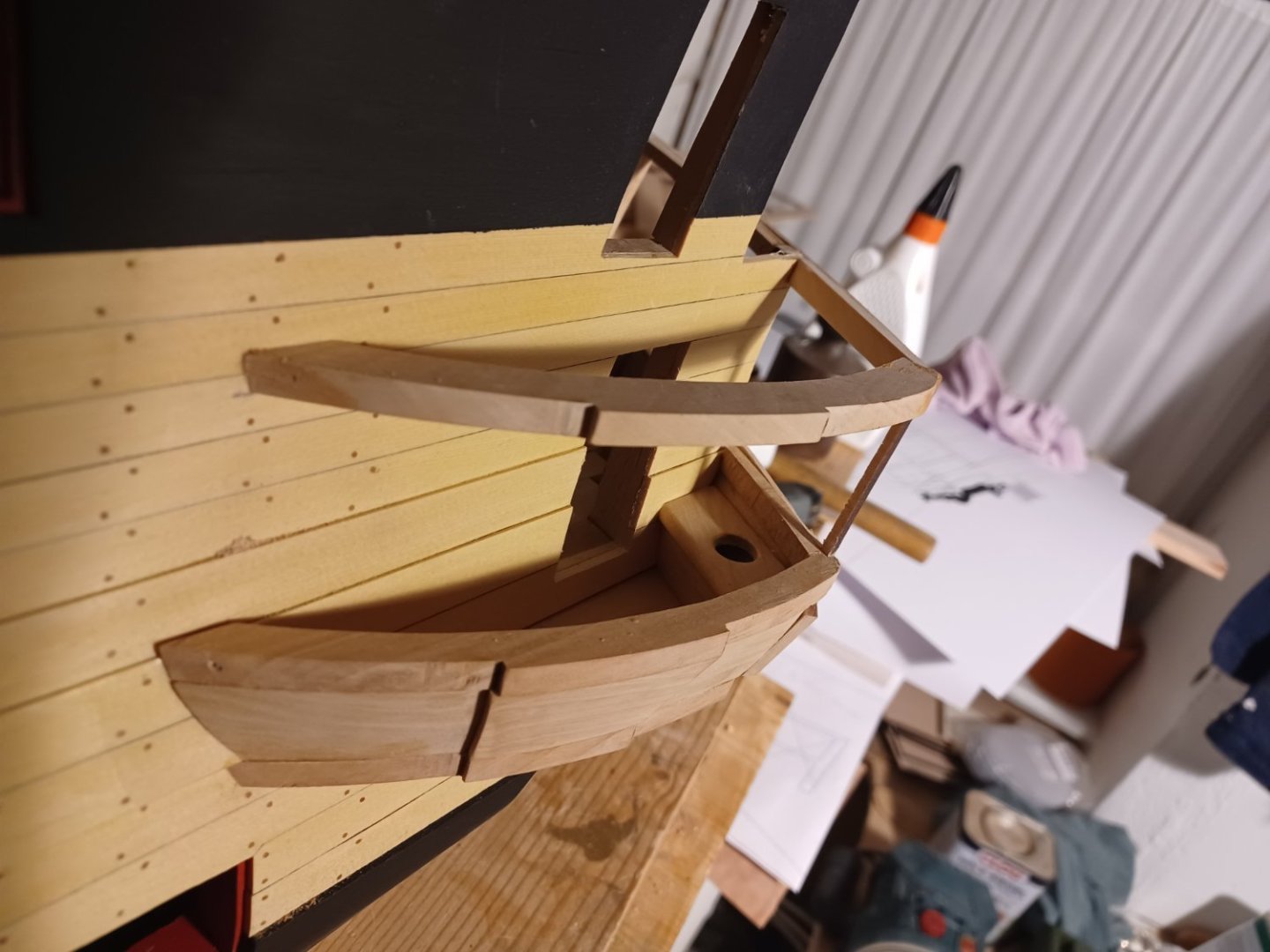
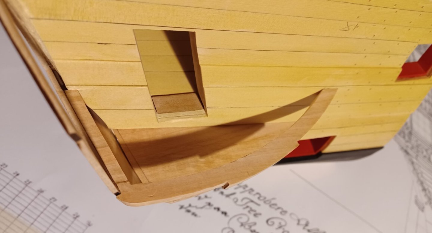
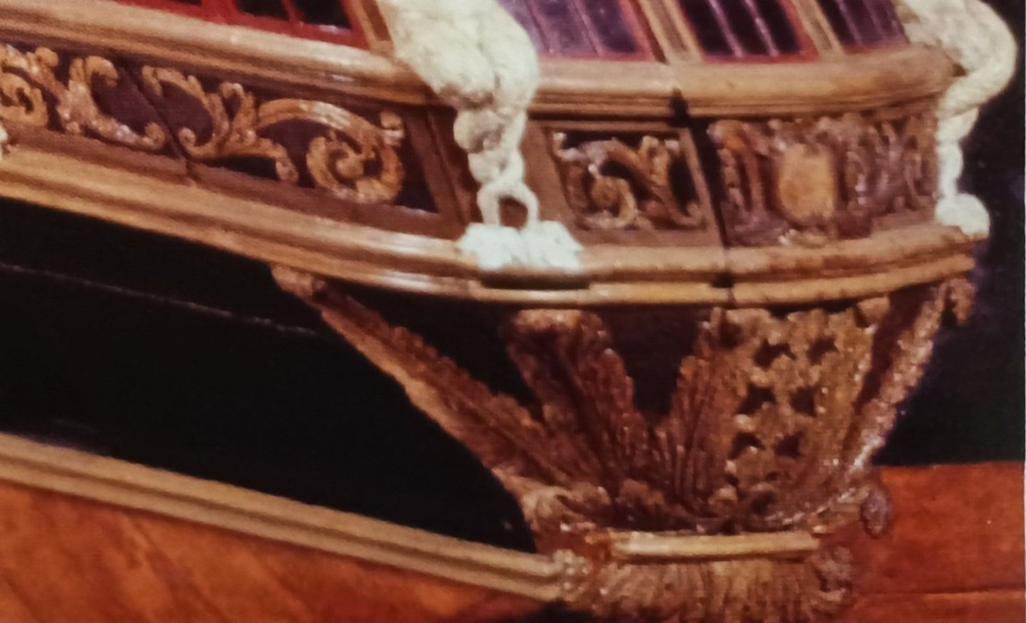
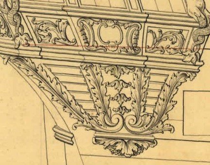
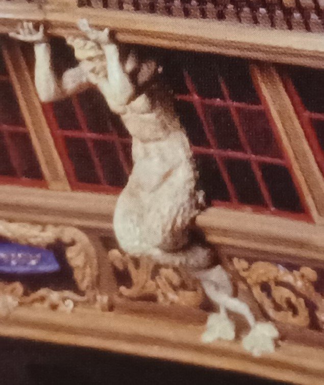
Hello Everybody, just a small update on the construction of the Quarter-Gallery. I started with the horizontal frames of the construction and added the lower front-panel. Having glued everything to the model, always checking the plans, I added the vertical parts and the seat of ease. The corner, where the Quarter-Gallery touches the stern gallery is not correct yet. I think now it must be round and not flat. I will overwork that next. It is hard to see this on the plans or on the contemporary model, because it is almost completely covered with the sculpture of the two-tailed merman. Matthias


-
Hi Chuck, that is good news, that produktion of Speedwell chapters will not be limited. I will take my time to finish my own 3/8" scale project and start with Speedwell later. Matthias
- 786 replies
-
- 5
-

-
- speedwell
- syren speedwell
- (and 1 more)
-
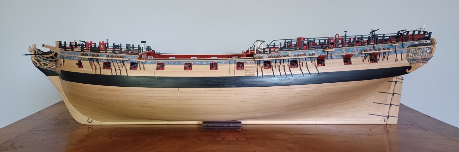
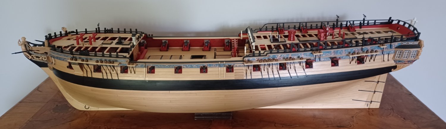
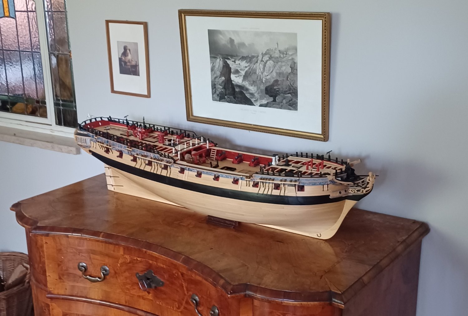
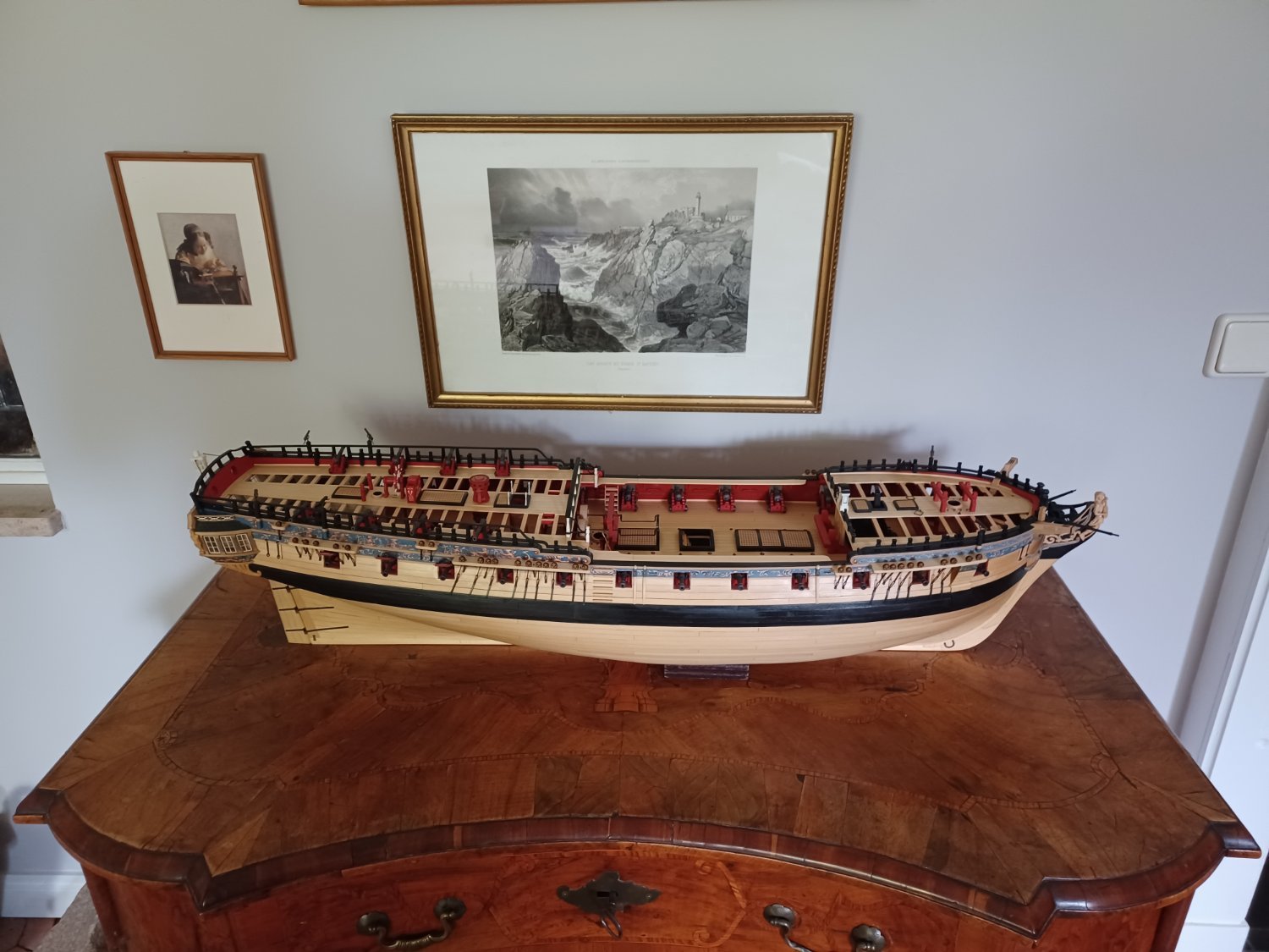
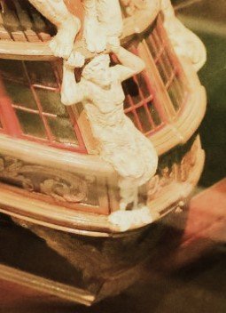
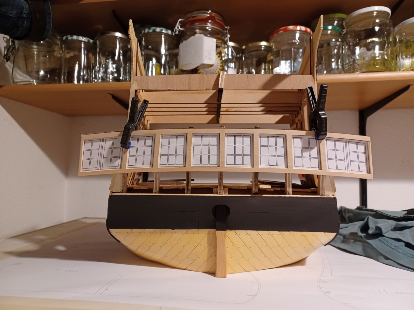
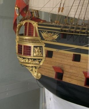
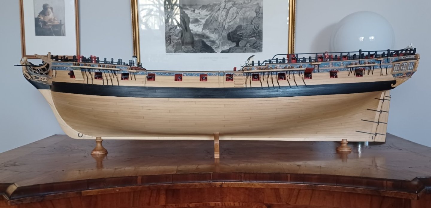
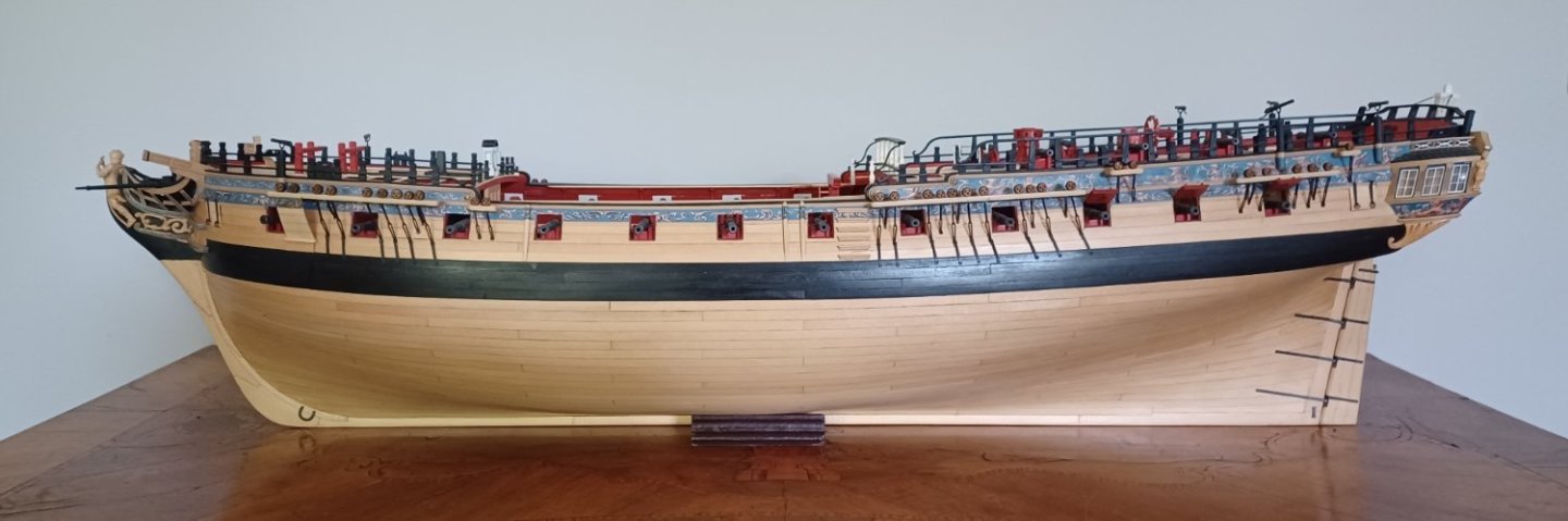
Hi Siggi, the original model is even shorter then mine. I made it a bit longer and added one gunport each deck to get a feeling for the size of the ship. This photo was taken in the museum, you can see how short it is. Matthias
-
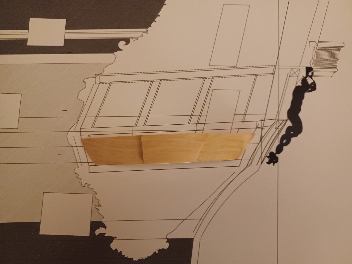
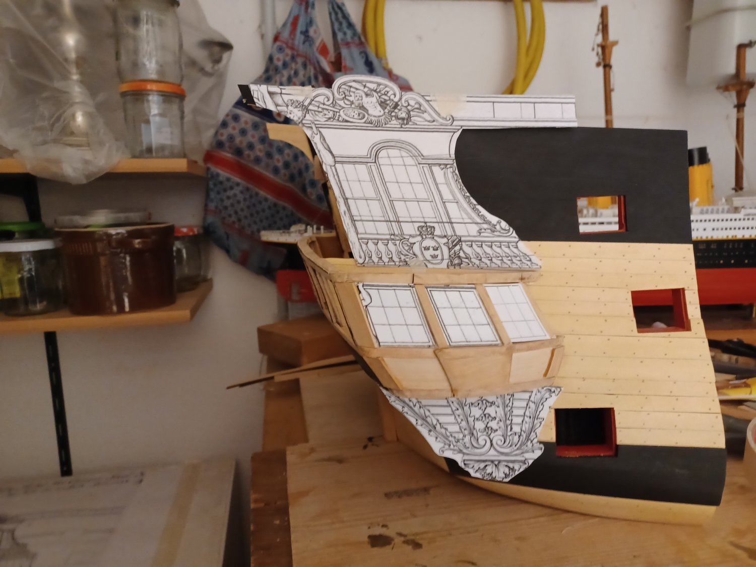
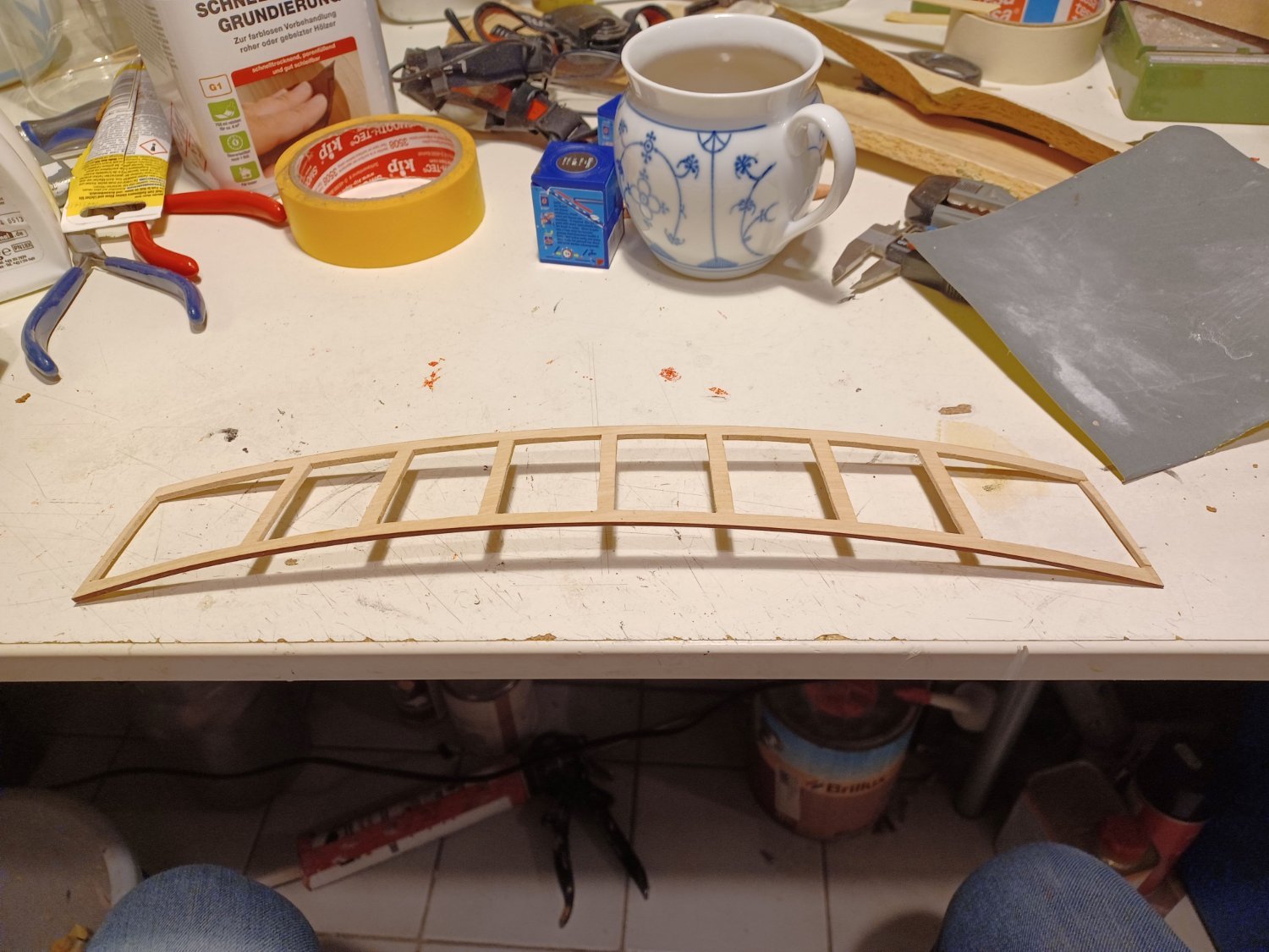
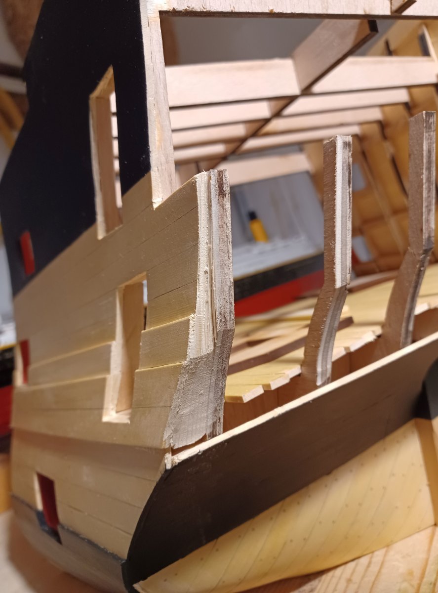
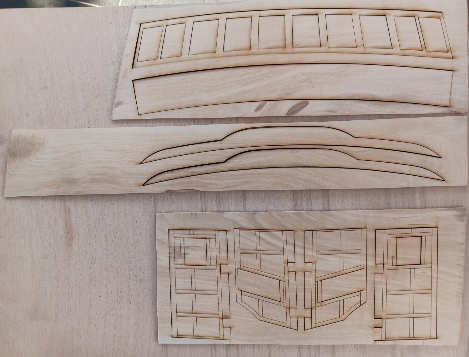
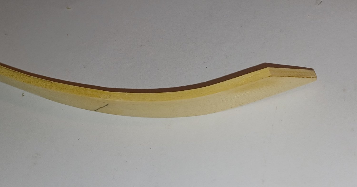
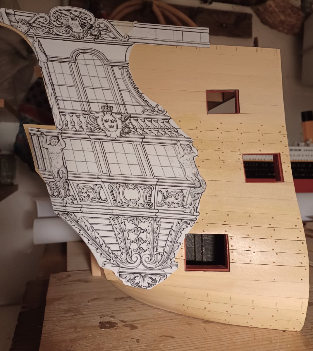
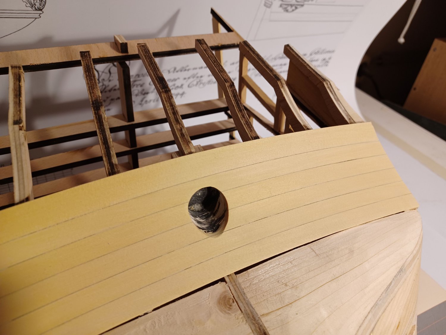
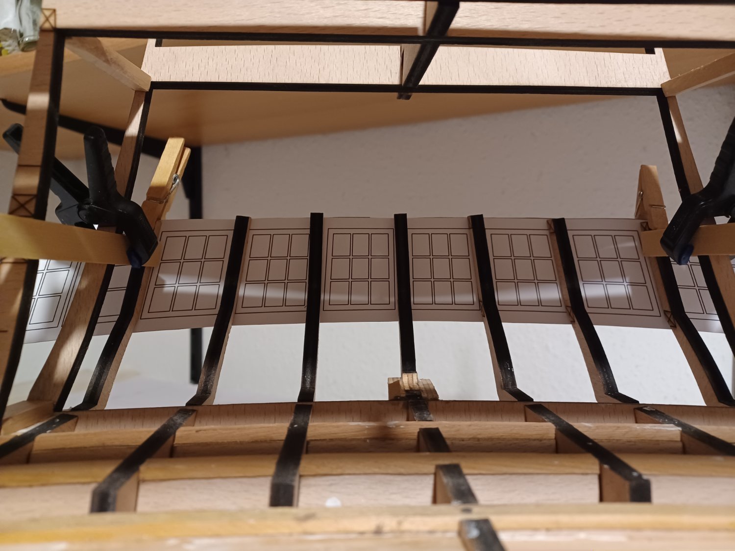
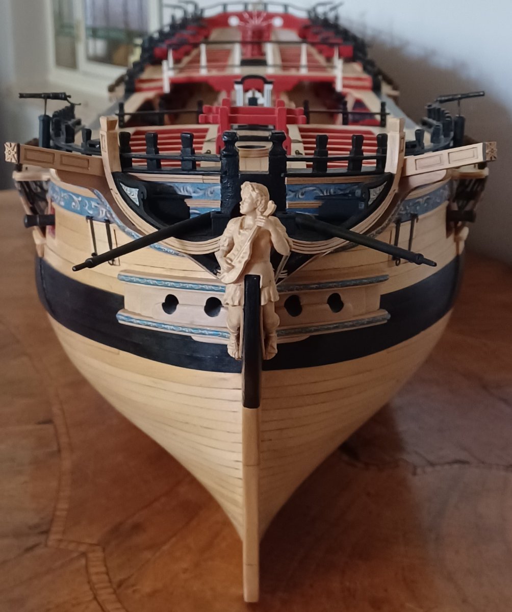
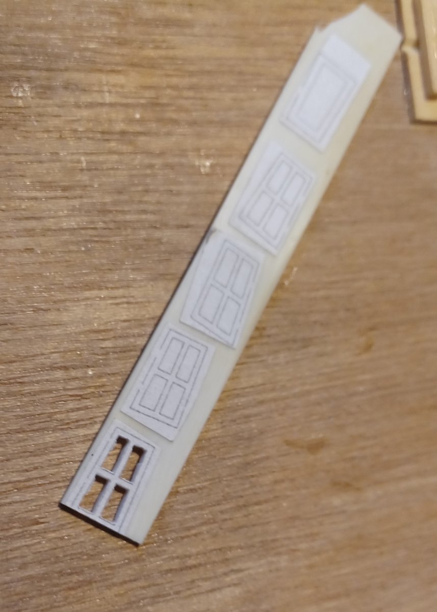
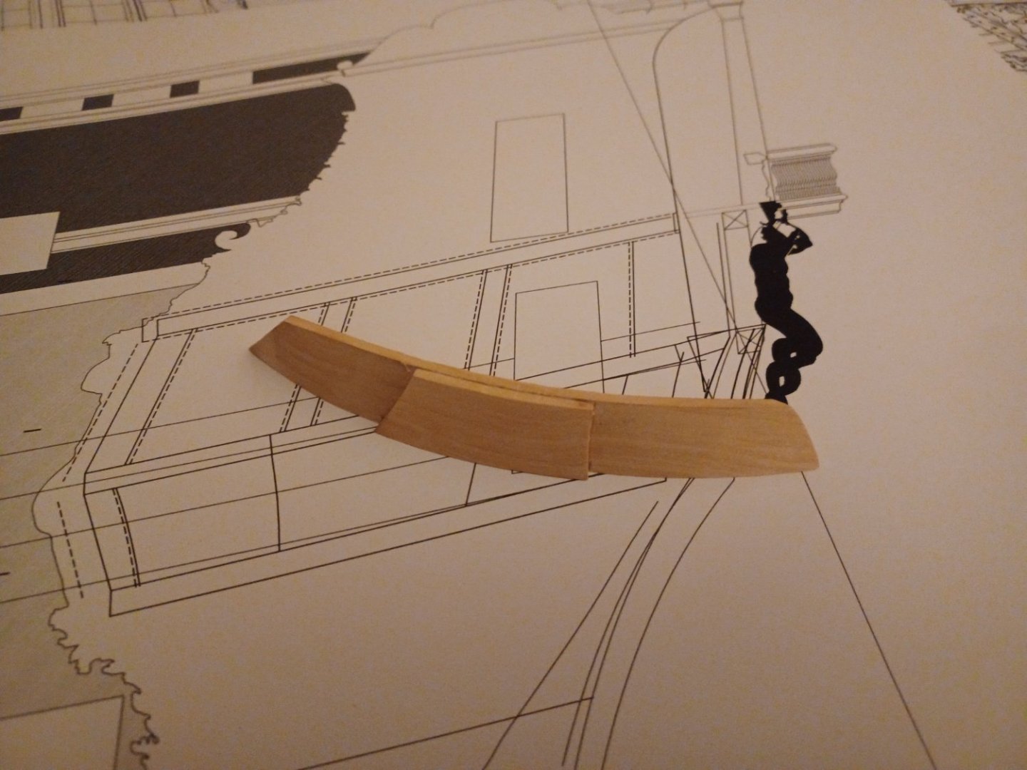
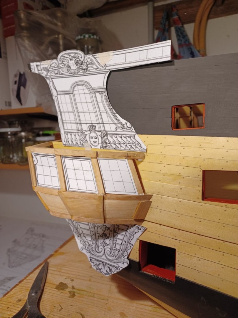
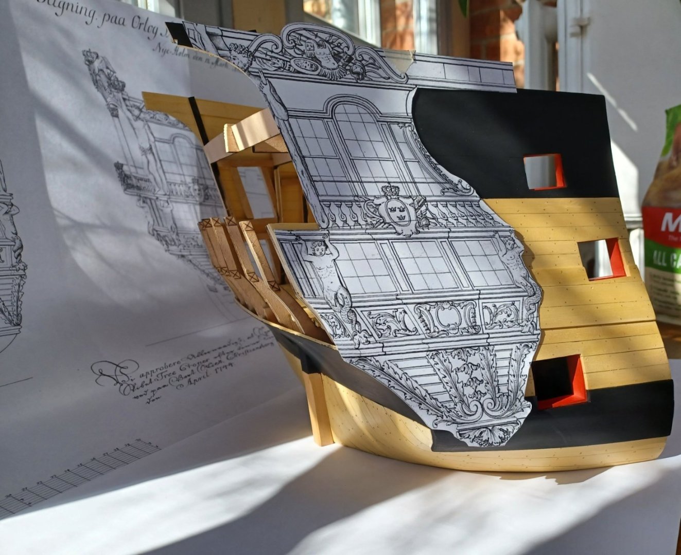
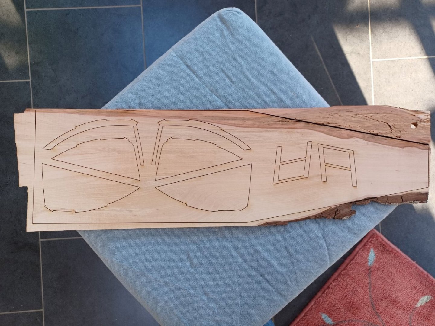
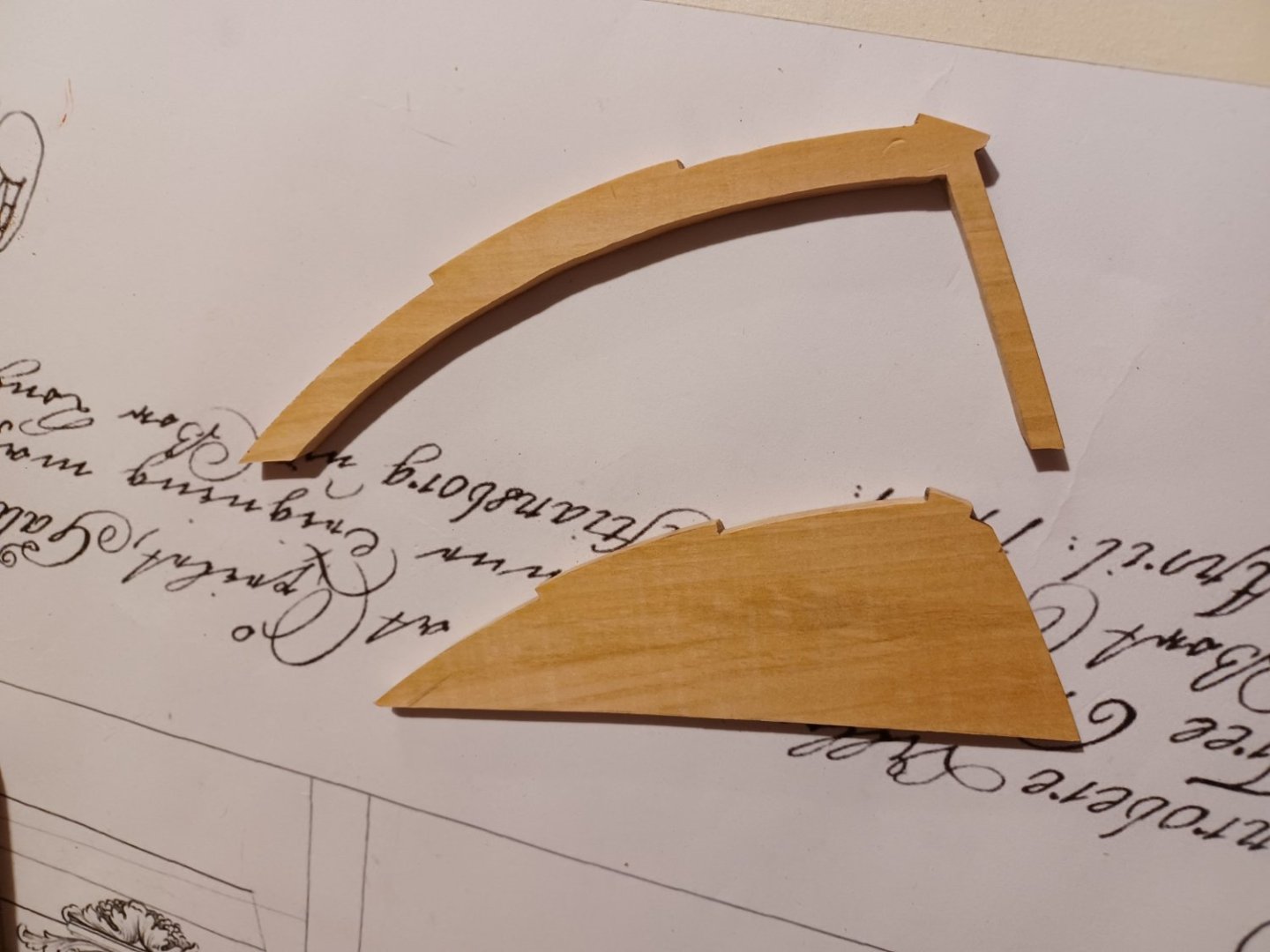
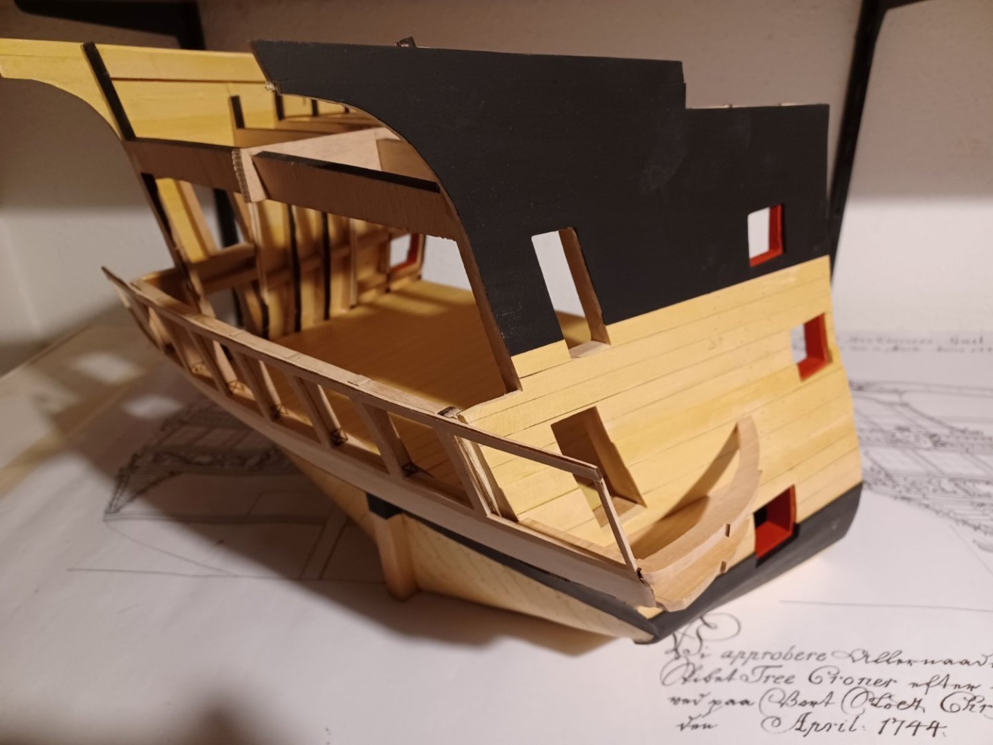
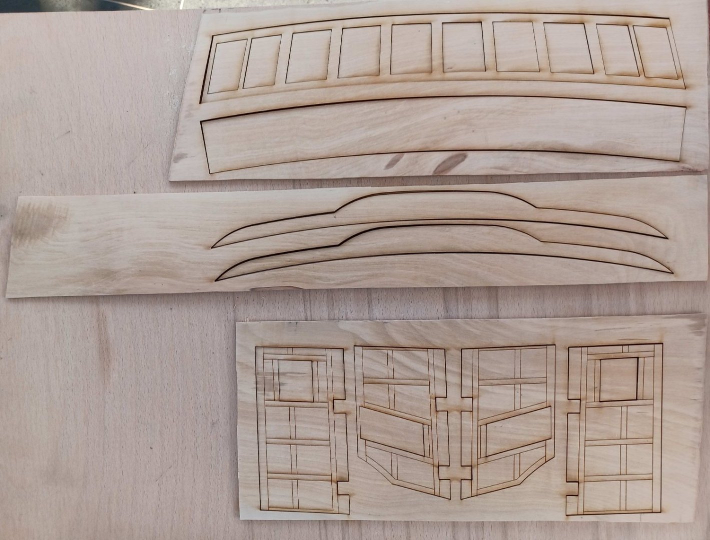
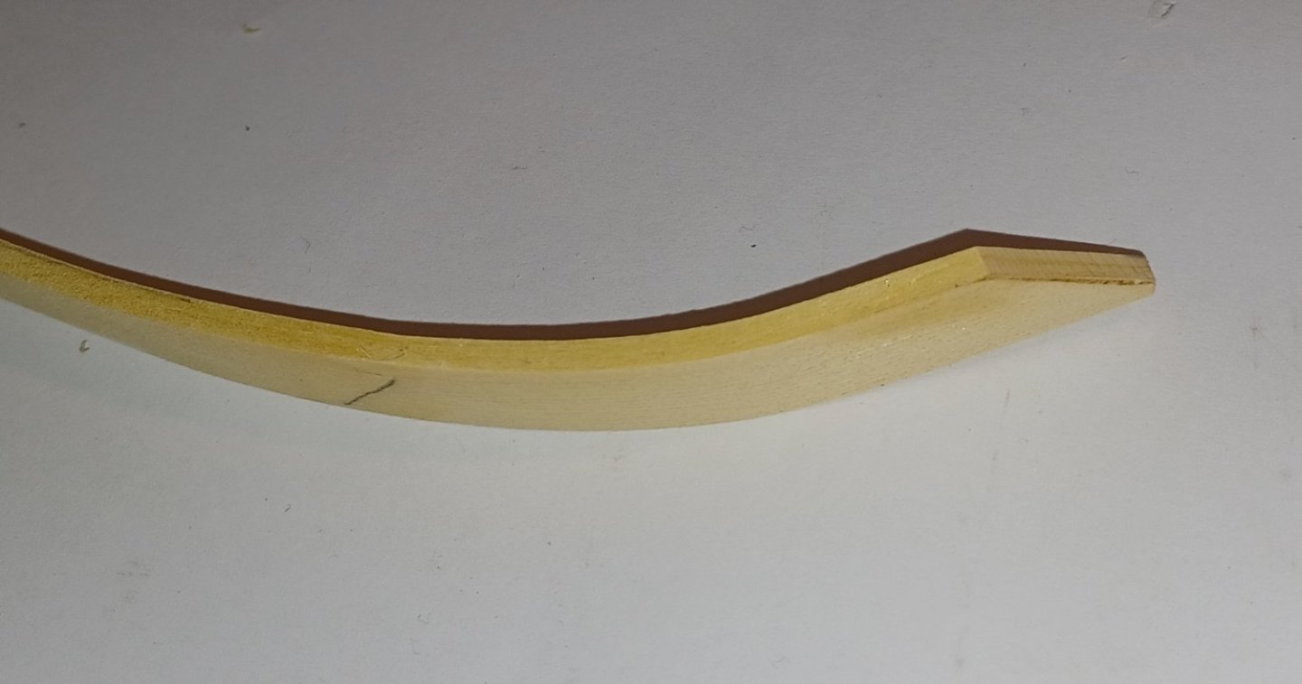
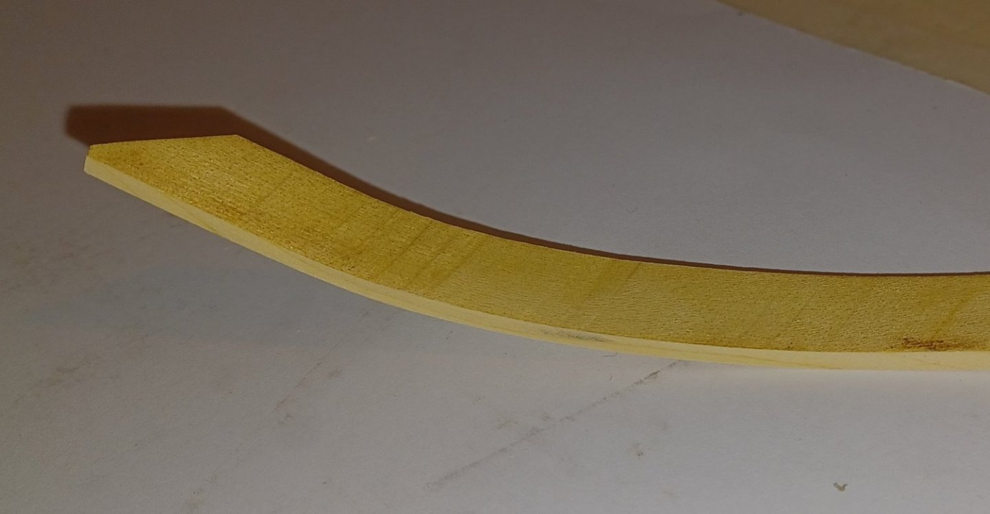
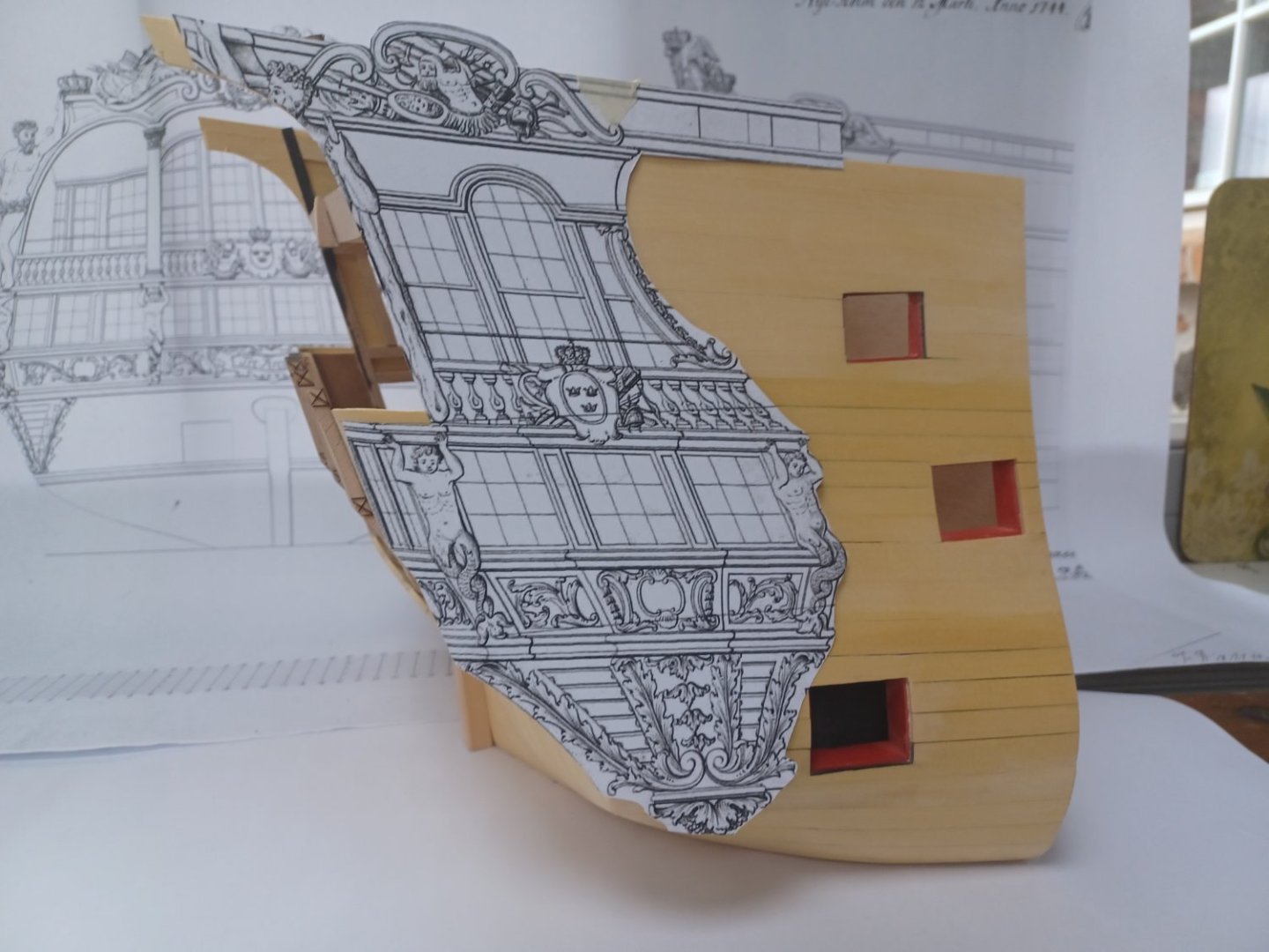
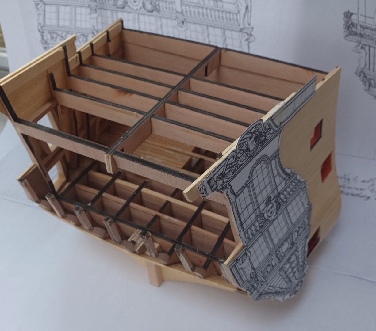
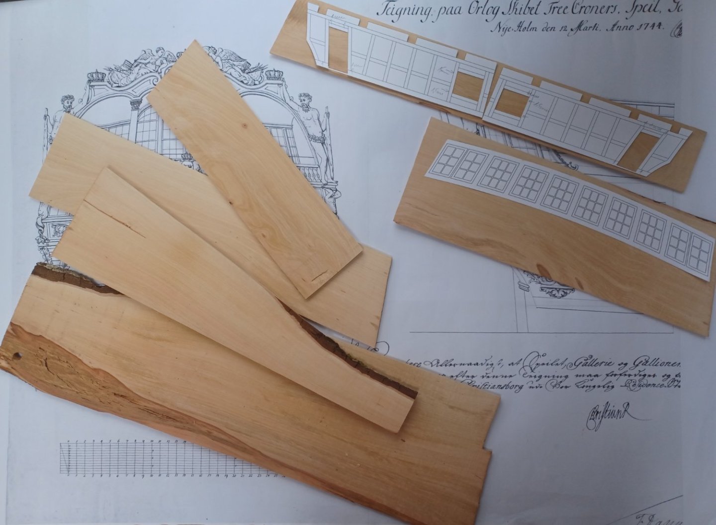
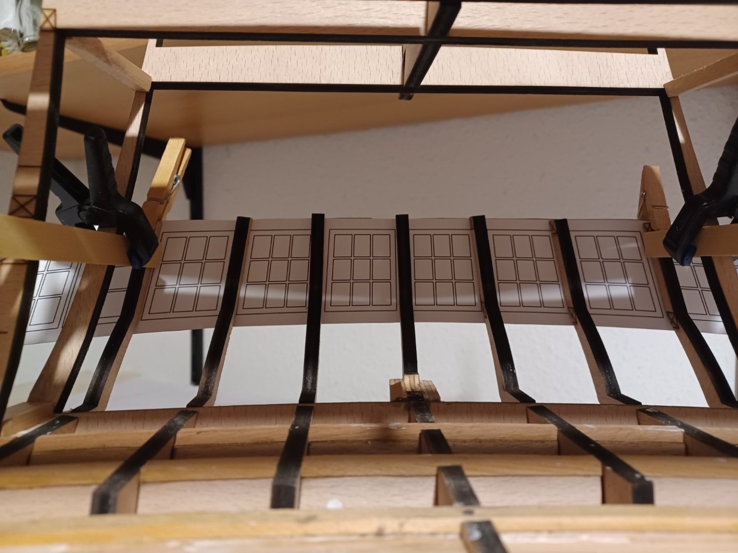
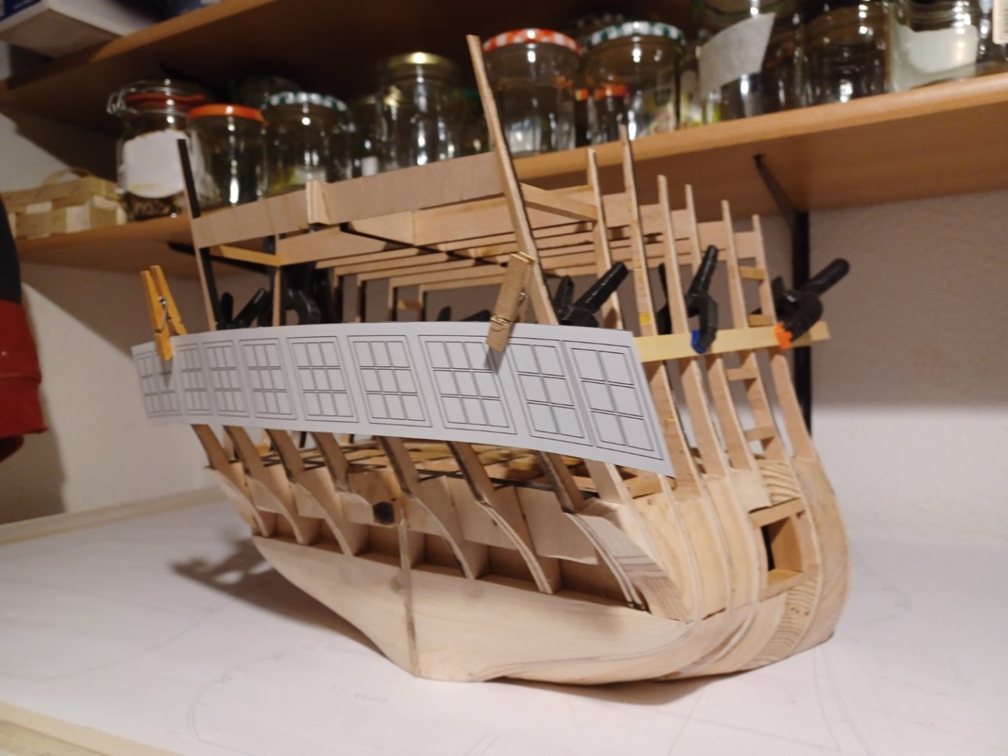
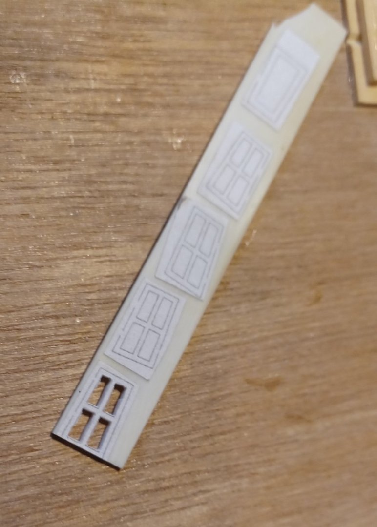
Hello everyone, The planking work on the hull segment is now almost complete. All the visible planks have also been nailed and the black surfaces such as the whales and bulwarks have been painted. The template shows the position of the quartergallery and will later be used to precisely position the horizontal sections of the QG. The sets of drawings from the Danish National Archives are very accurately drawn. There are hardly any contradictions between the actual construction plans and the ornamental drawings. This is very helpful. Here are the prepared parts for the next construction stages The prospectus for the lower gallery windows follows next. It is moulded in advance with moisture and heat. The first structural elements of the quartergalleries now follow. The curved frame elements form the horizontal structure. On top there will be the fancy moldings. These are curved and also jump back and forth in several positions. That will be fun. The surfaces up to the windows are closed in line with the shape and are later subdivided into individual fields, which are filled with ornamental carvings. The overall composition is very much the French Baroque style and differs a lot from englisch ships of comparable size and age. Matthias


-
Thank you, yes I will try different ways to approach the carvings. At the moment I am cutting the blocks for the figures, my boxwood is a bit fresh, because I cut it only 4 weeks ago, I want to get it dry in time. Matthias
-
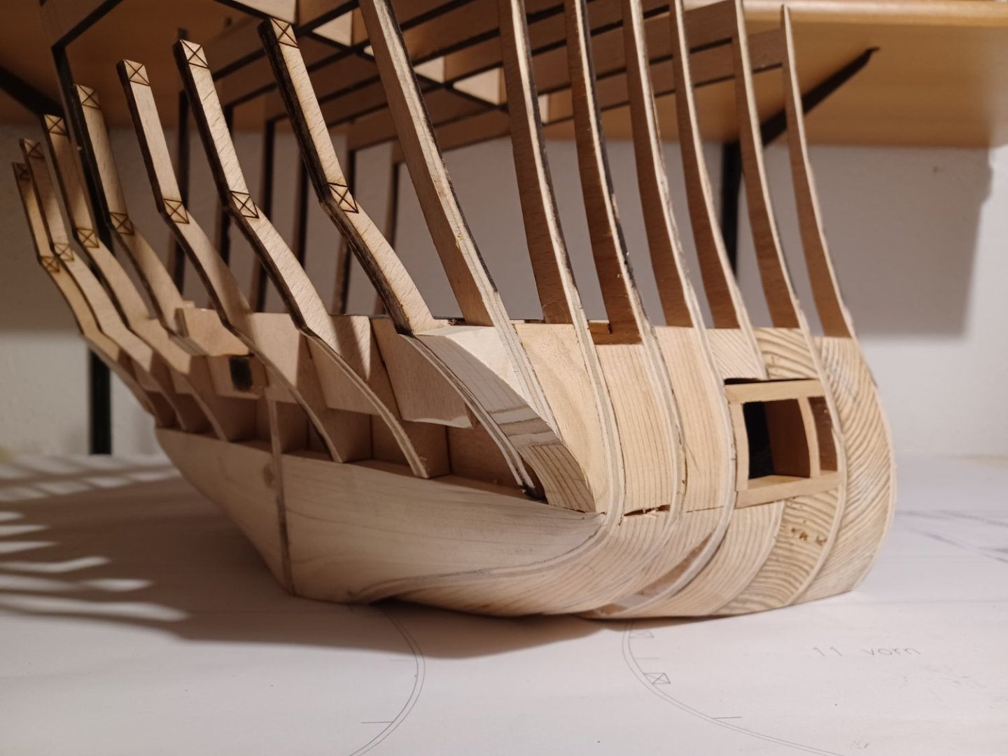
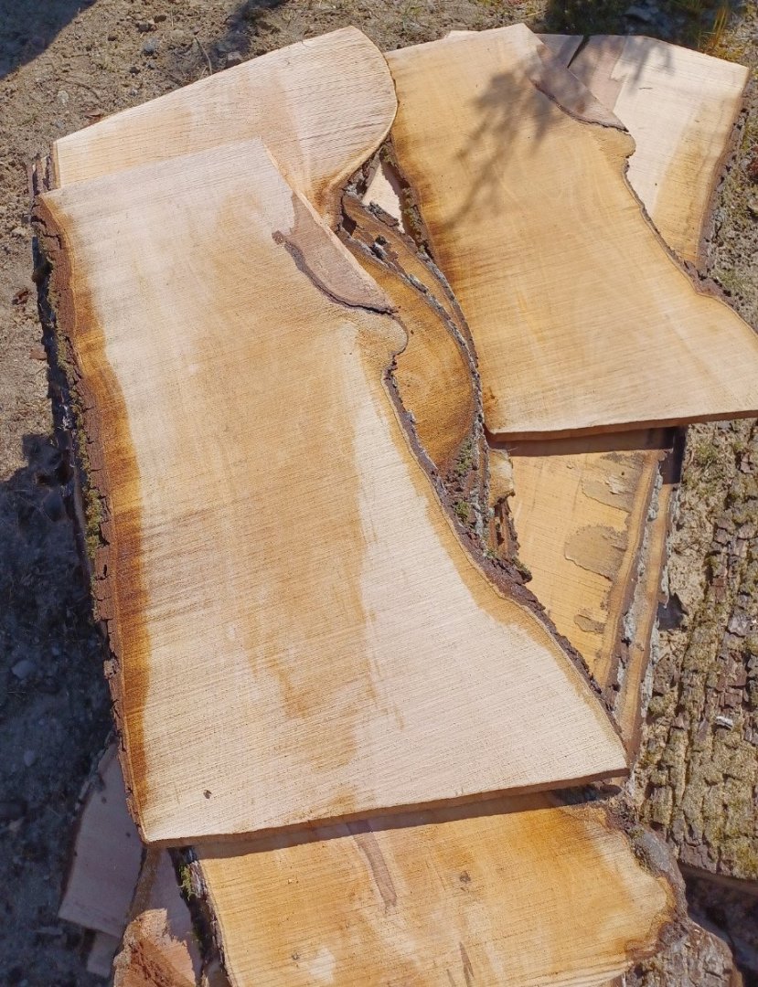
Hello Everybody, the last weeks I was busy, planking the model. Bending and twisting of planks with dimenson of 2/13 and 2/11 mm was more challenging than I thought ist would be. The curves in the lower areas of the model are very narrow. Here you can see some pictures of the progress. After this was done, I faired everything. The colours will be like other contemporary models from the Krigsmuseet in Copenhagen. Model of CHRSITIAN DEN SIETTE Model of FYEN I decided to nail the bright parts of the hull. After finishing this, I will paint the black areas of the hull an start building the stern and quartergalleries. I already made the drawings of most of the parts and tested them on the model and prepared the wood to be laser-cut. It ist all pear-wood I cut in a garden close to the place to our village. Matthias


.jpg.cf2d588bb6b10cf805c531f051d1c1e6.jpg)
-
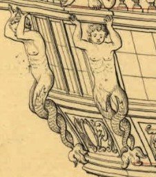
Hello Greg, I know, that the carvings will be the real challenge in this. The rest of the model is just the stage for them. If the carvings don't come out compelling, the whole model won't be. Ther are two types of carvings, the flat ornament and the figures. I plan to work from bottom to top. So the first carvings will be the flat ornaments of the quartergallery and the transom. I will draw them digitally and get them laser cut in 3 mm boxwood. Then I carve them in detail by hand. Luckily, the plans and photos are detailled and in scale, so that will help a lot. After that, I plan to approach the 6 Watermen who carry the balcony. My CAD skills are more in 2D-construction. I don't have the software and the time to make digital 3D-figures. I will propably try different ways. The original model has them carved in wax. One could consider that. Carving wax is still in use for industrial design purpose. But these figures would be very fragile. Sculptors use 2K-modelling-clay, this is intersting, because you can form them easily, and carve this afterwards and add missing or broken areas. The third method is of couse carving them in wood. I made more simple wood carvings in the past. I carved animals and other figures for the toy farm of the kids, but this is much more challenging. I will propably try all methods and see, what happens. Matthias
-
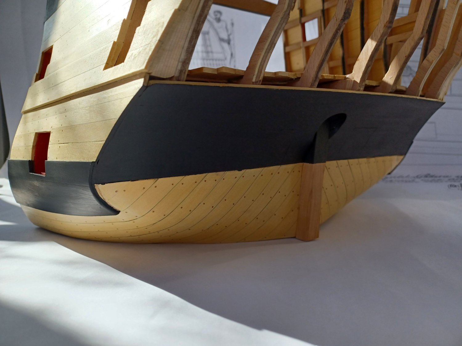
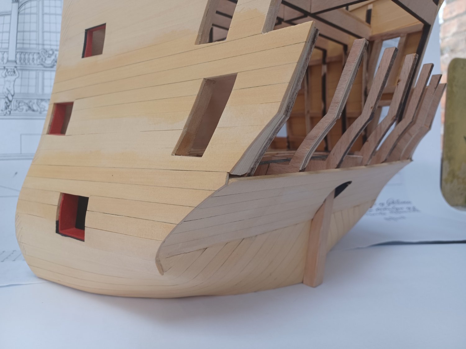
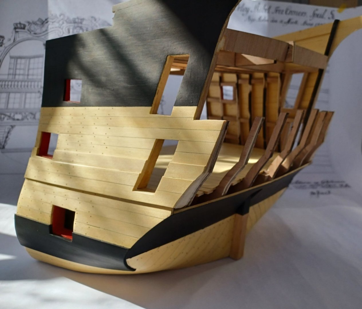
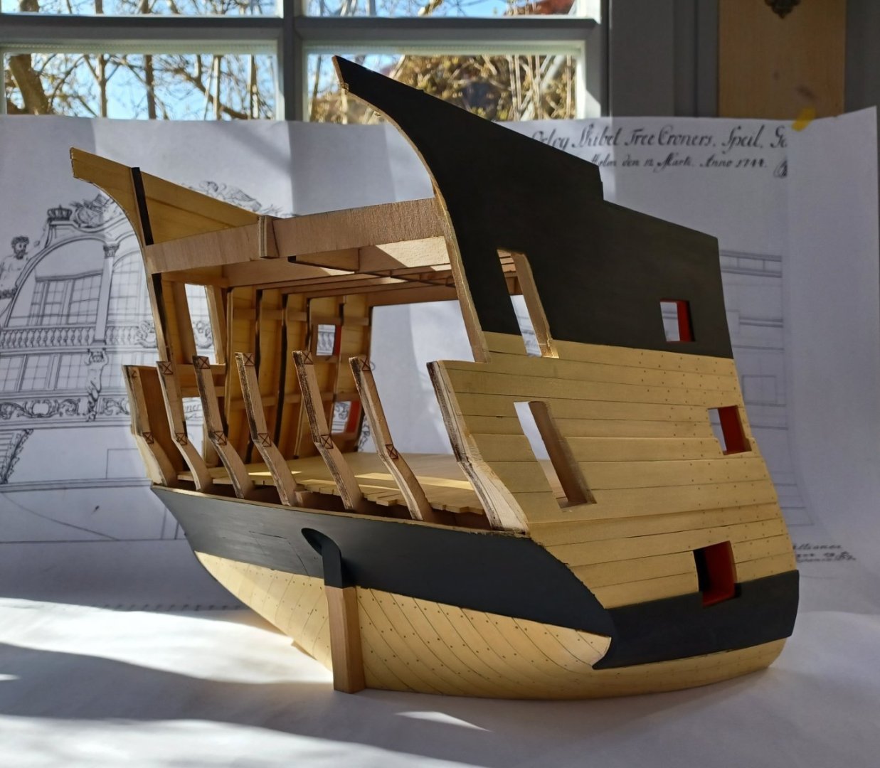
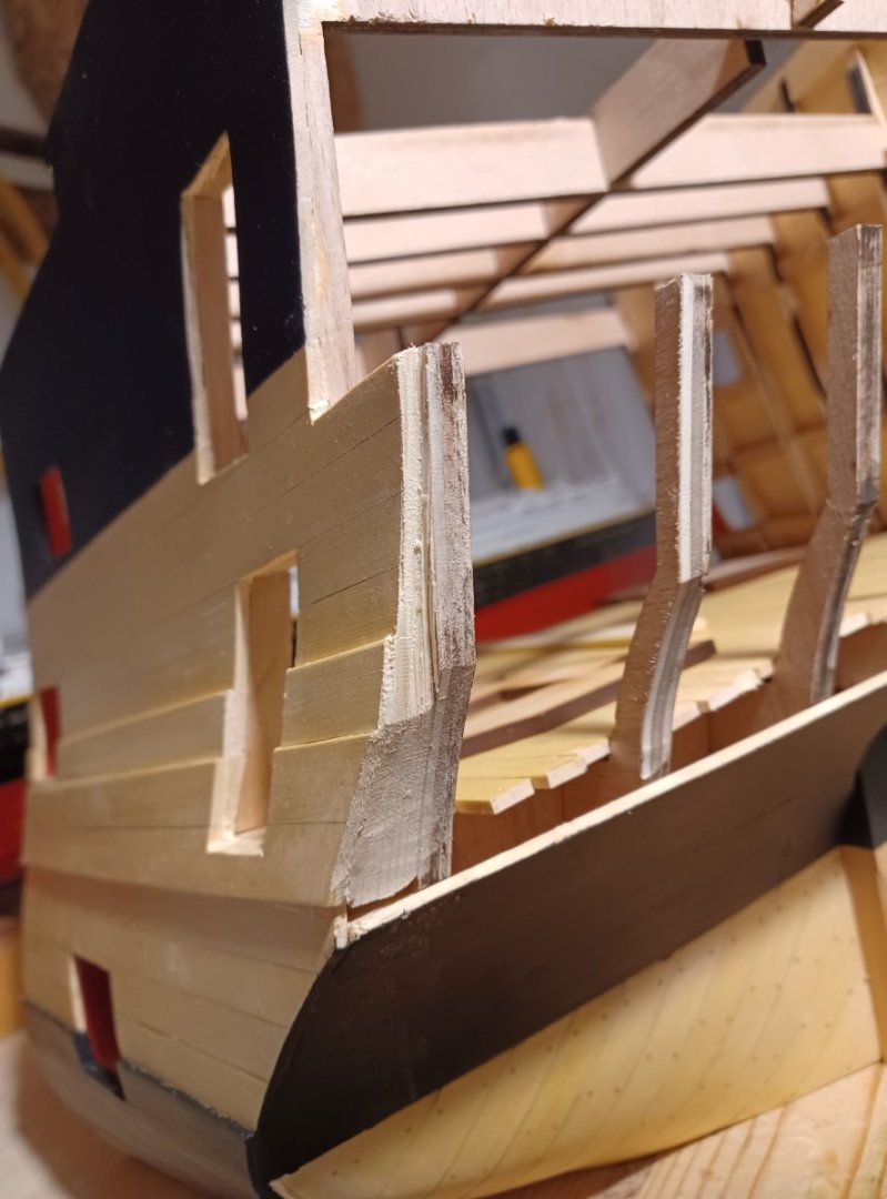
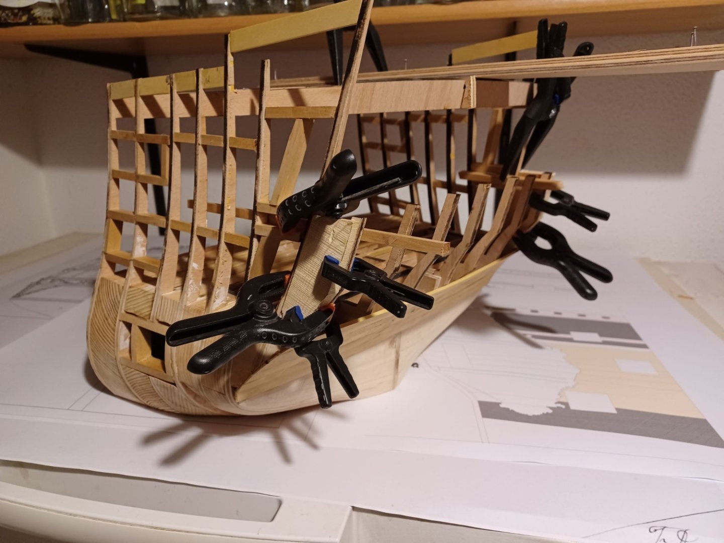
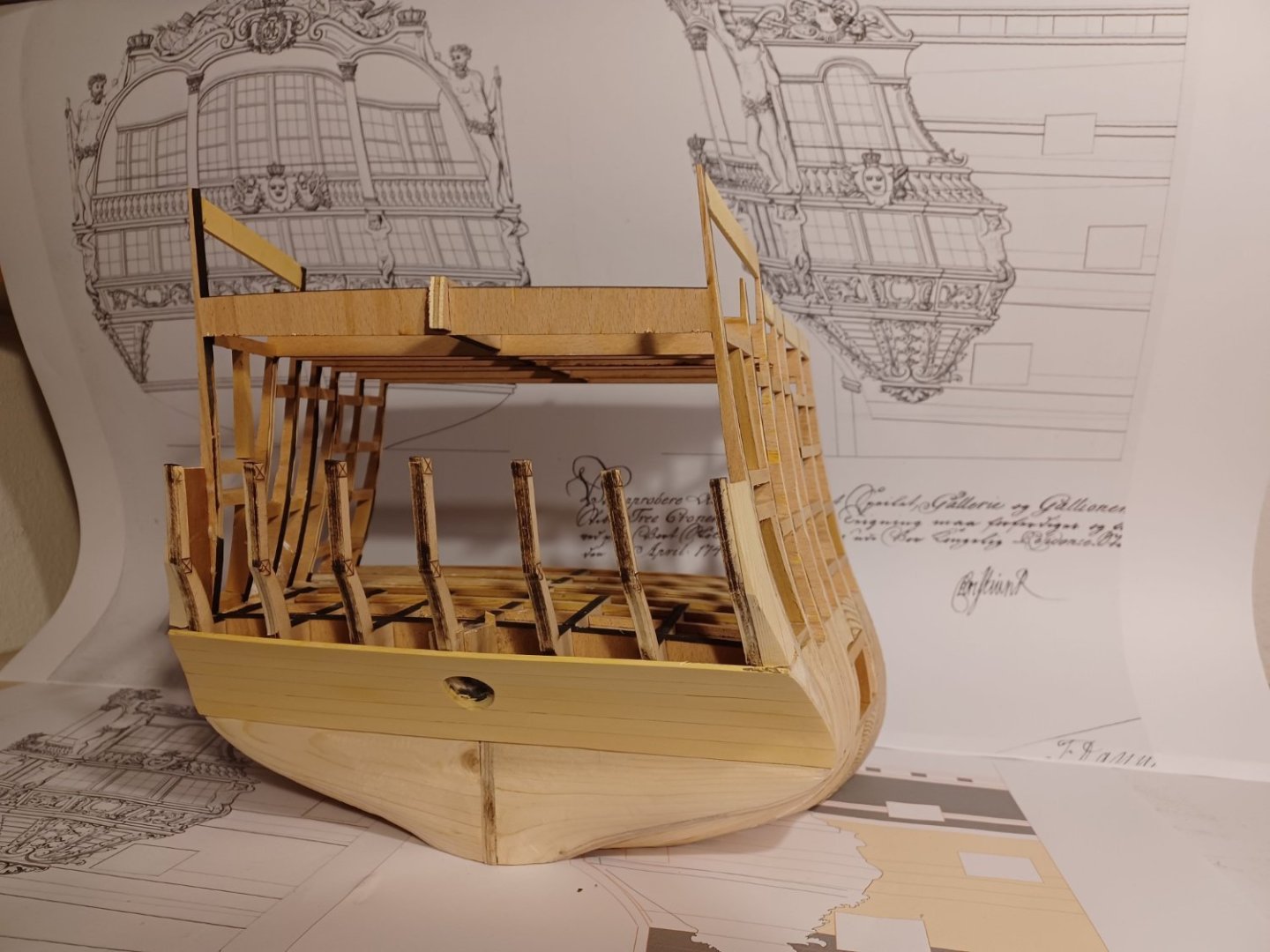
Thank you , The framing is now finished and I sanded all the fillers and gunport-frames. After that the transom was planked and the opening for the rudder-head was made. The next steps involve planking the outside of the side walls. Before I start with this, the planking layout has to be precisely defined. In principle, I had already done this in the area of the front bulkhead, but I'll have to check again whether it still works in the stern area. Matthias


-
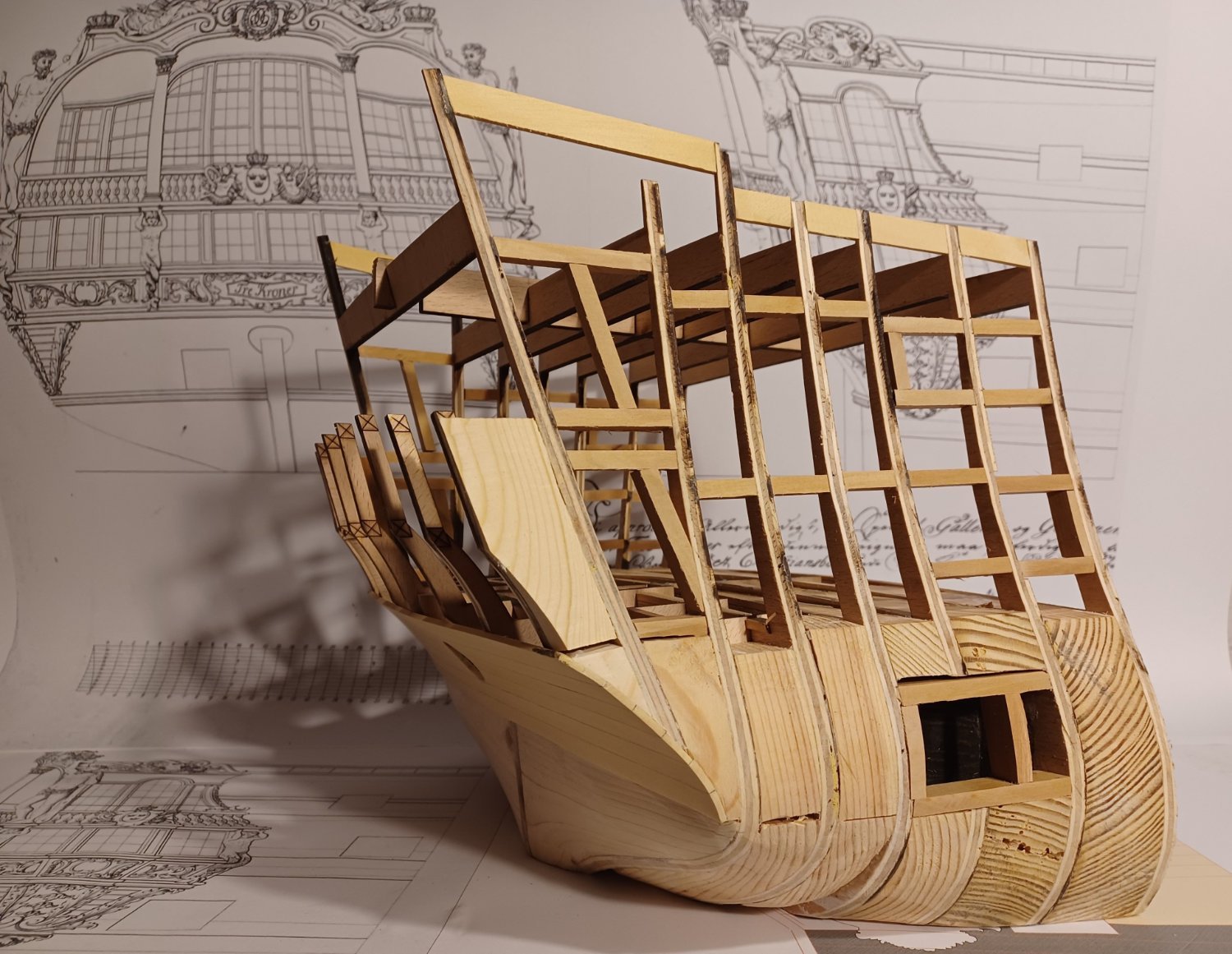
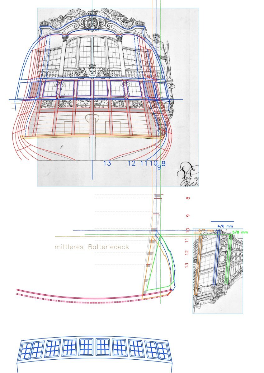
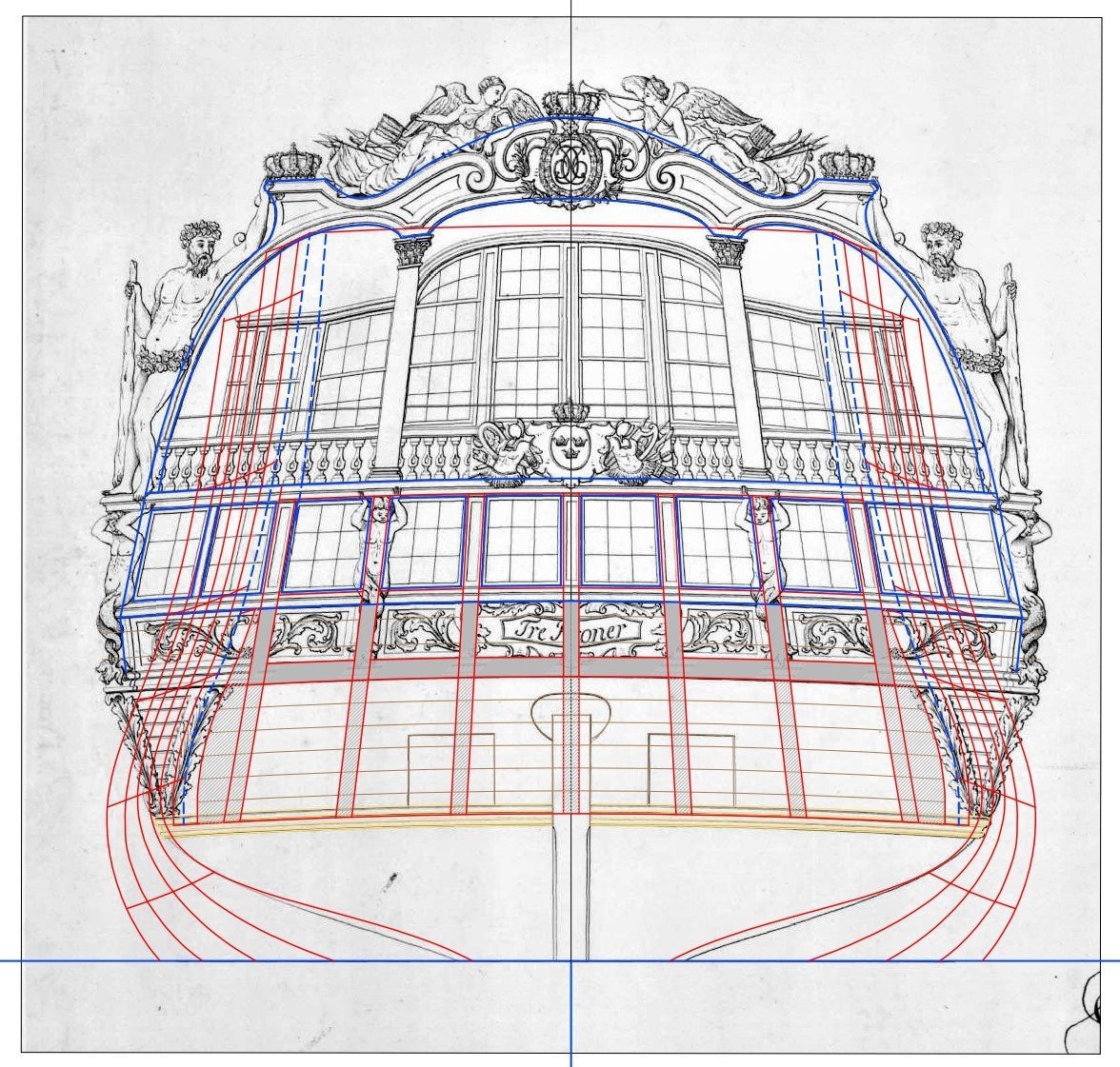
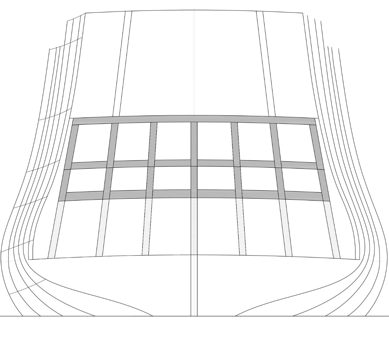
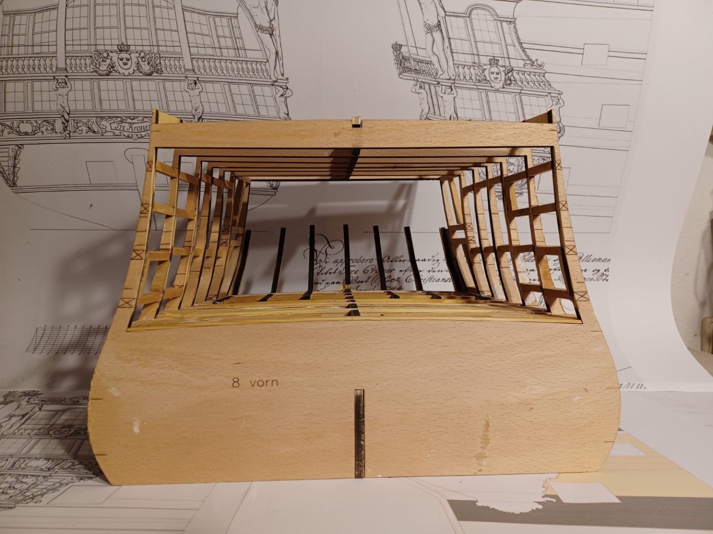
Hello everybody, the last week, I continued assemblying the bulkheads an gluing solid fillers into the lower-gundeck part. There will be a tiny "black box" behind the gunport. The fillers werd sanded in shape, so the planking should have a nice run. The more complicated parts will be of course the construction of the quarter-galleries and the stern gallery. I make the CAD-drawings and test them with paper-templates. So far, everything seems to be okay. But before getting parts to be laser-cut, I need to complete the framing and get the hull planked. Here you see the procedure of constructing the quarter-galleries. Matthias

-
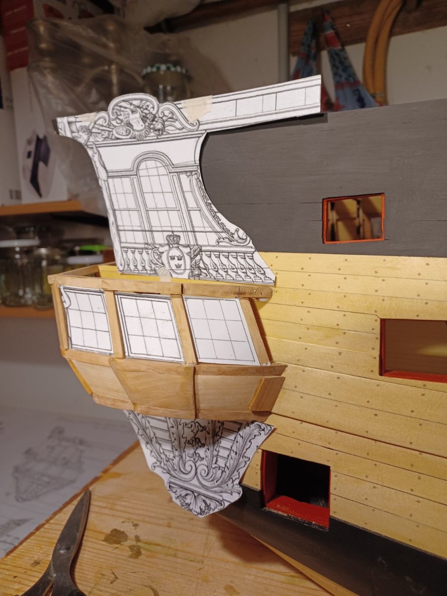
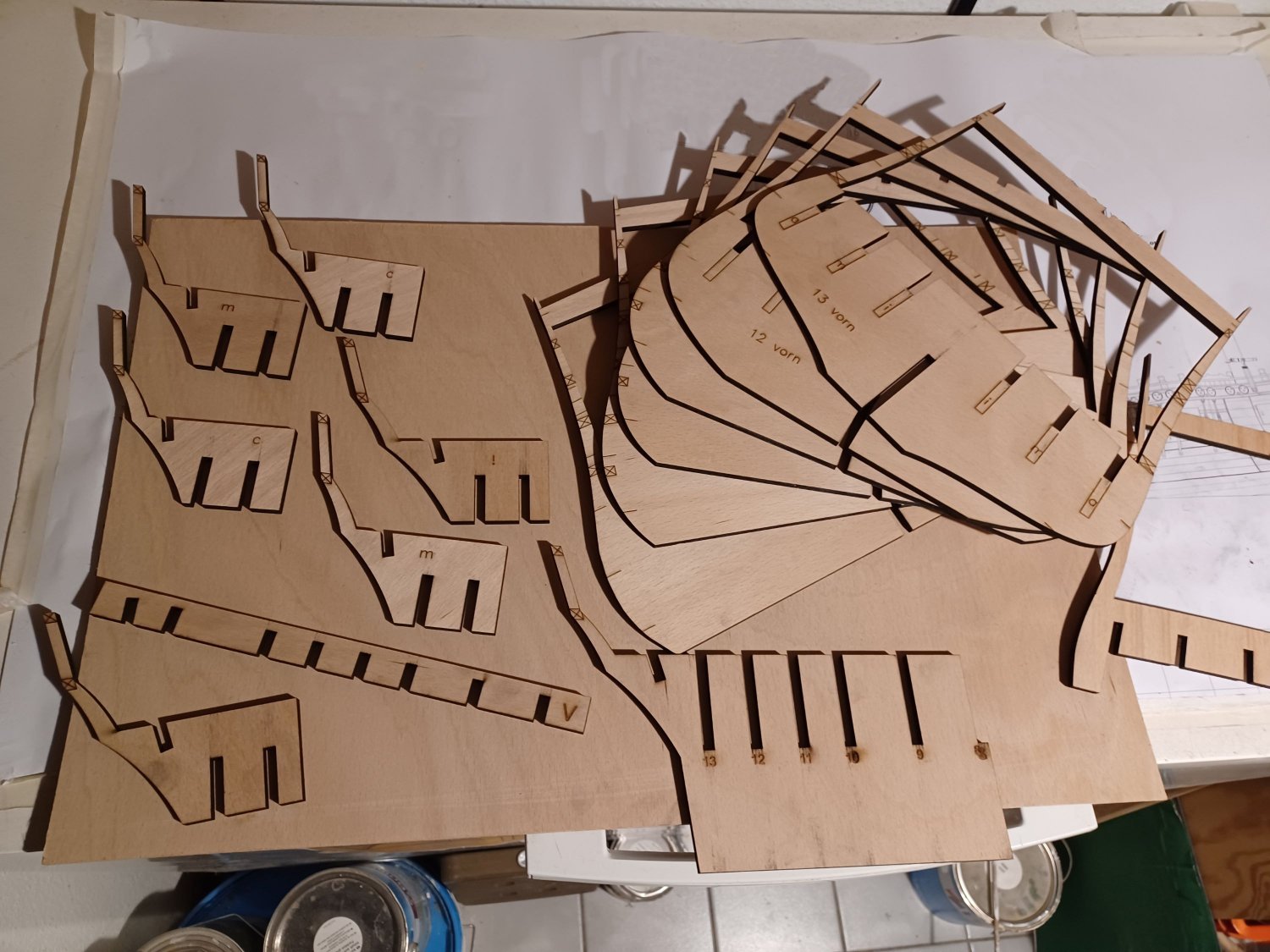
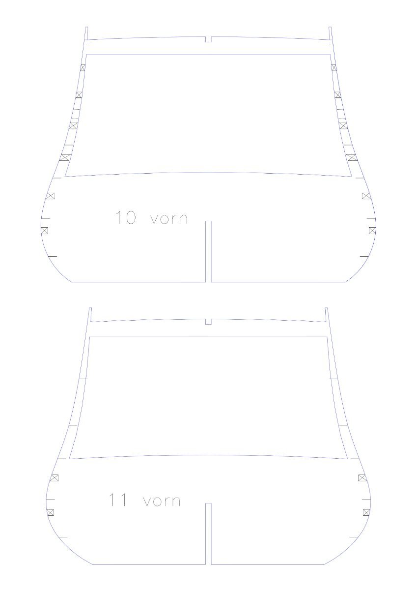
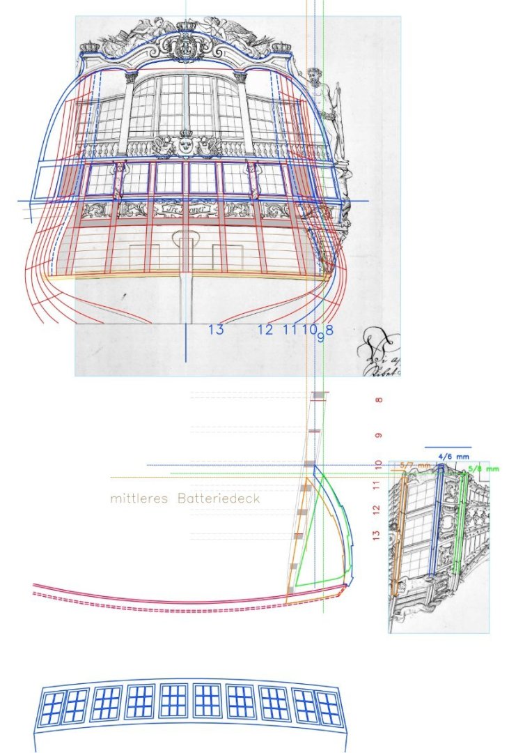
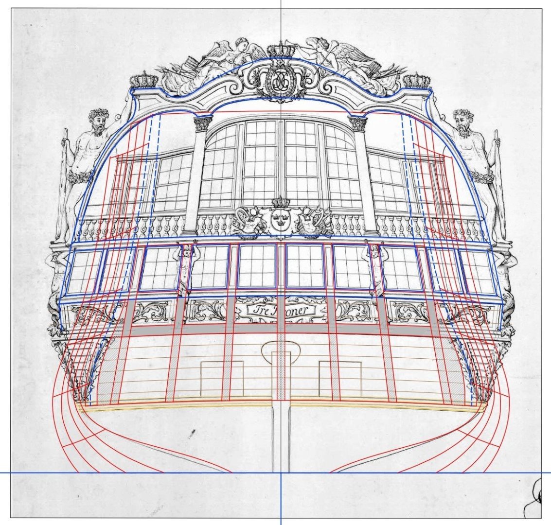
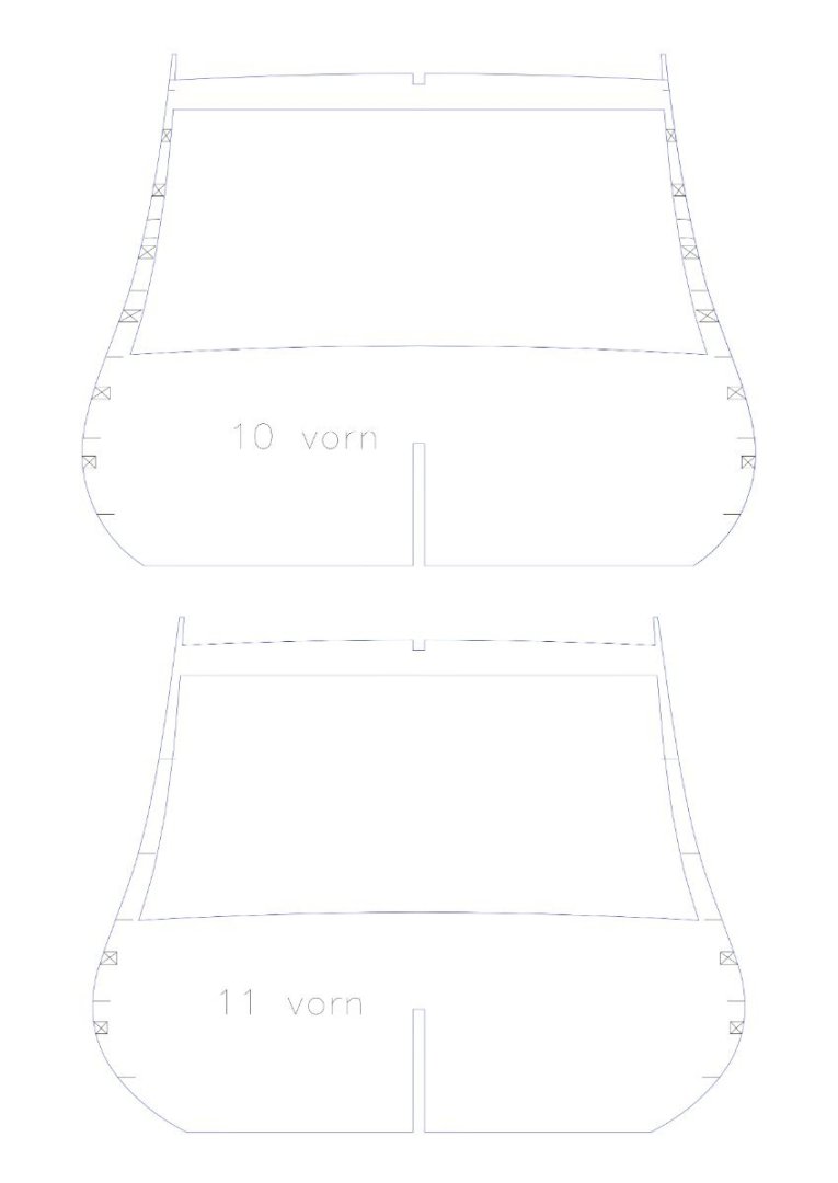
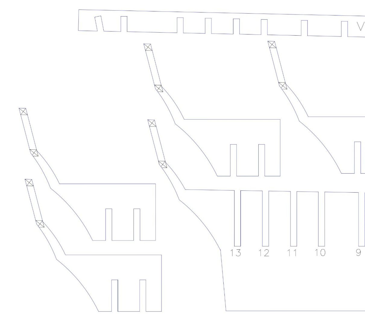
In this drawing, the main shaping components are shown in blue here. I have pulled the rear front into the perpendicular, as it is inclined in the view, in order to obtain the actual unfoldings for the components. I can then use this drawing to cut out the shape of the lower gallery later (material thickness approx. 2 mm), the upper sheet must then be cut from approx. 38 mm thick solid wood, as it is curved and has a material thickness of approx. 8 mm. (25 cm in the original) Between the penultimate and third-last windows of the lower rear gallery, as seen from the outside, the side wall meets the window front, which then continues over the side gallery. Here, at least the inner window must have been designed as a blind window, if not both outer windows. I had the parts laser-cut from 6 mm plywood, here you can see the pile of puzzle pieces: At first glance, everything seems to have worked out. The parts are a bit loose, as 6 mm plywood is often not 6 mm thick, but rather 5.7 mm. I should have held the sliding gauge to it again beforehand, but it will work. Everything fits together for now... Matthias

-
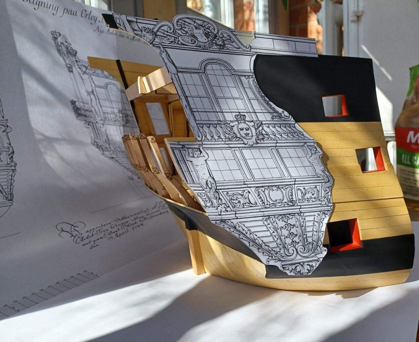
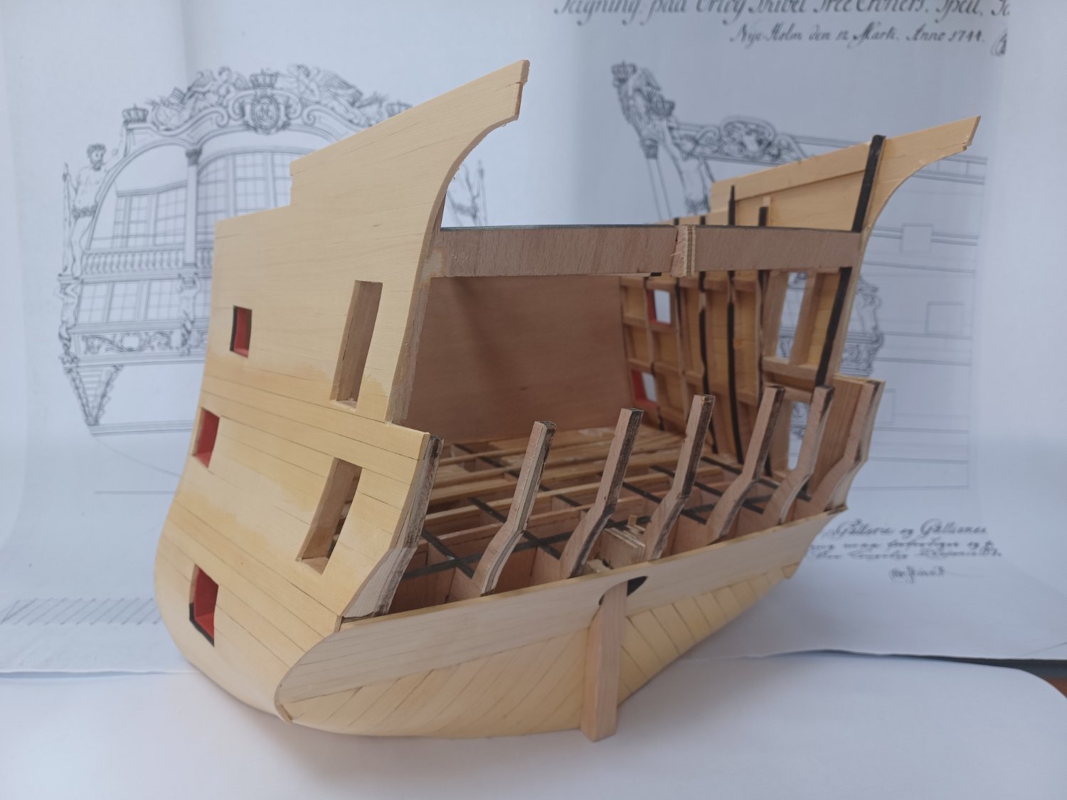
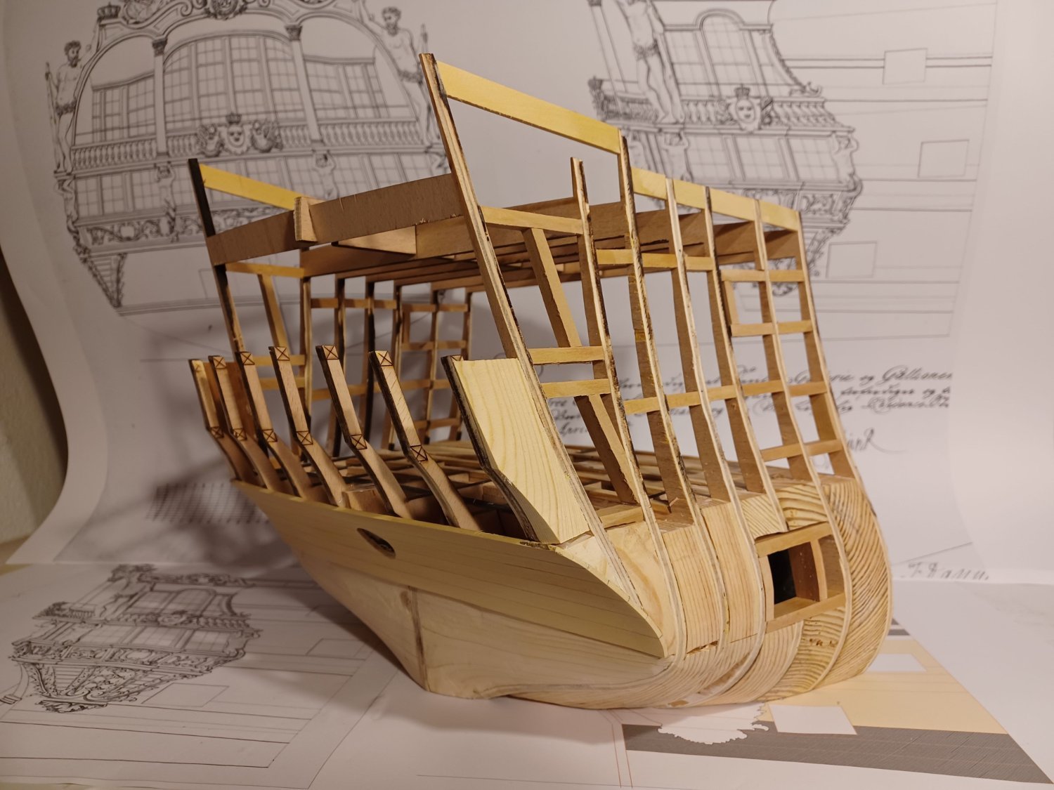
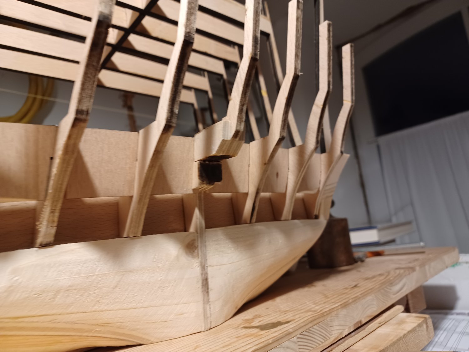
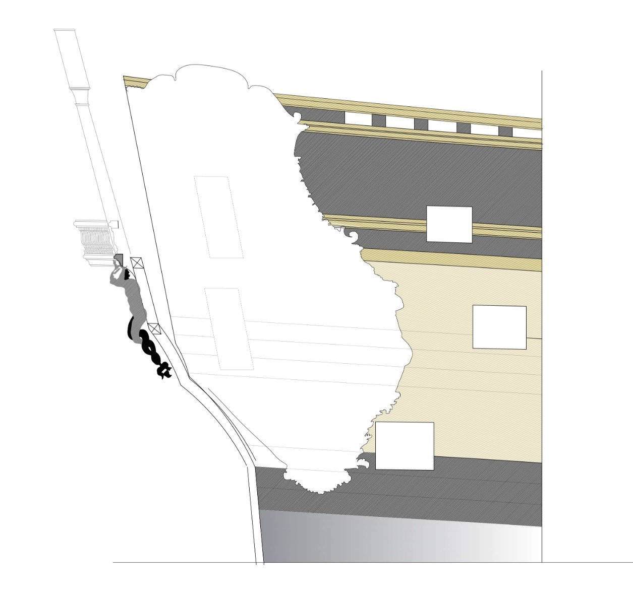
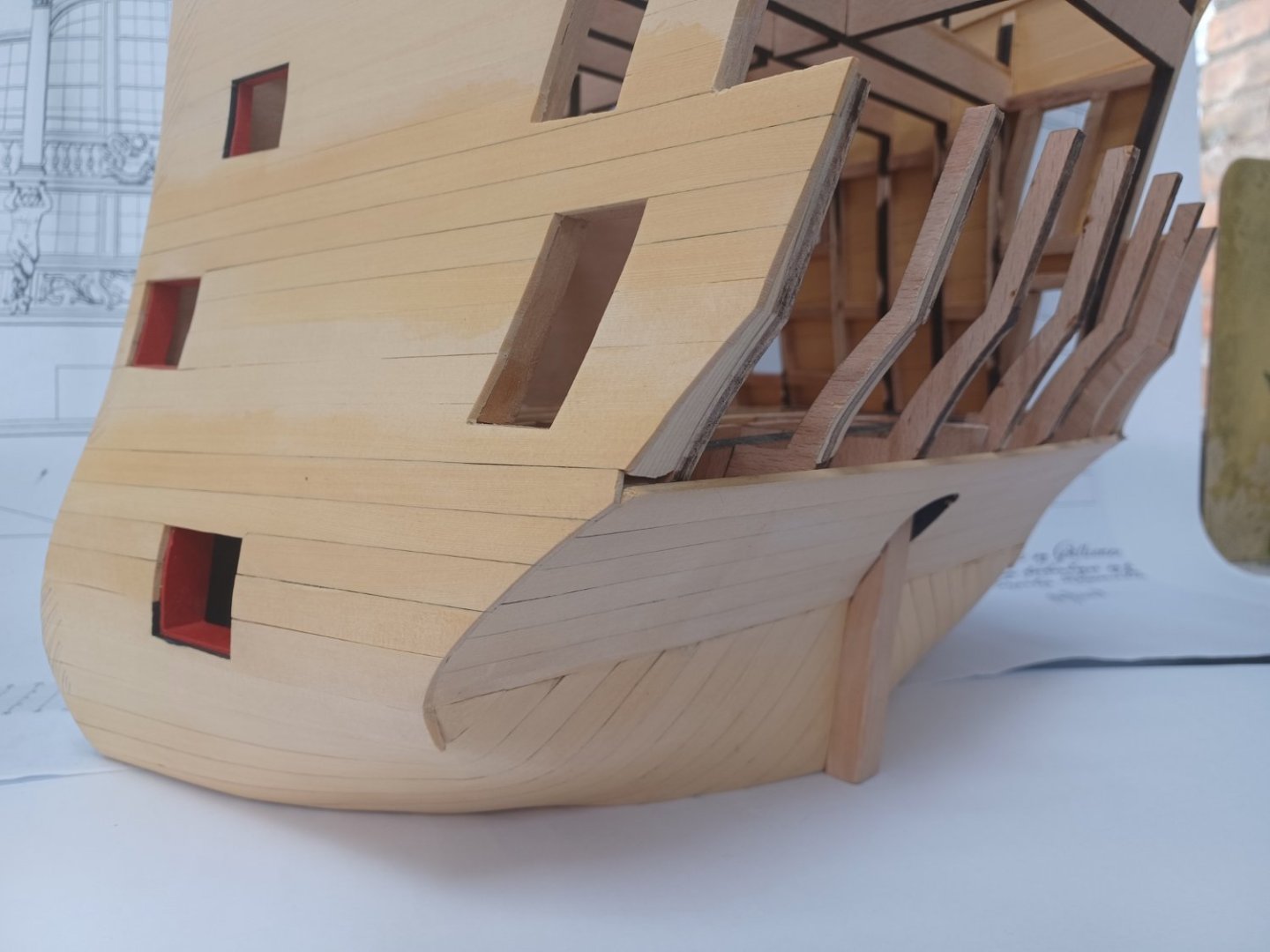
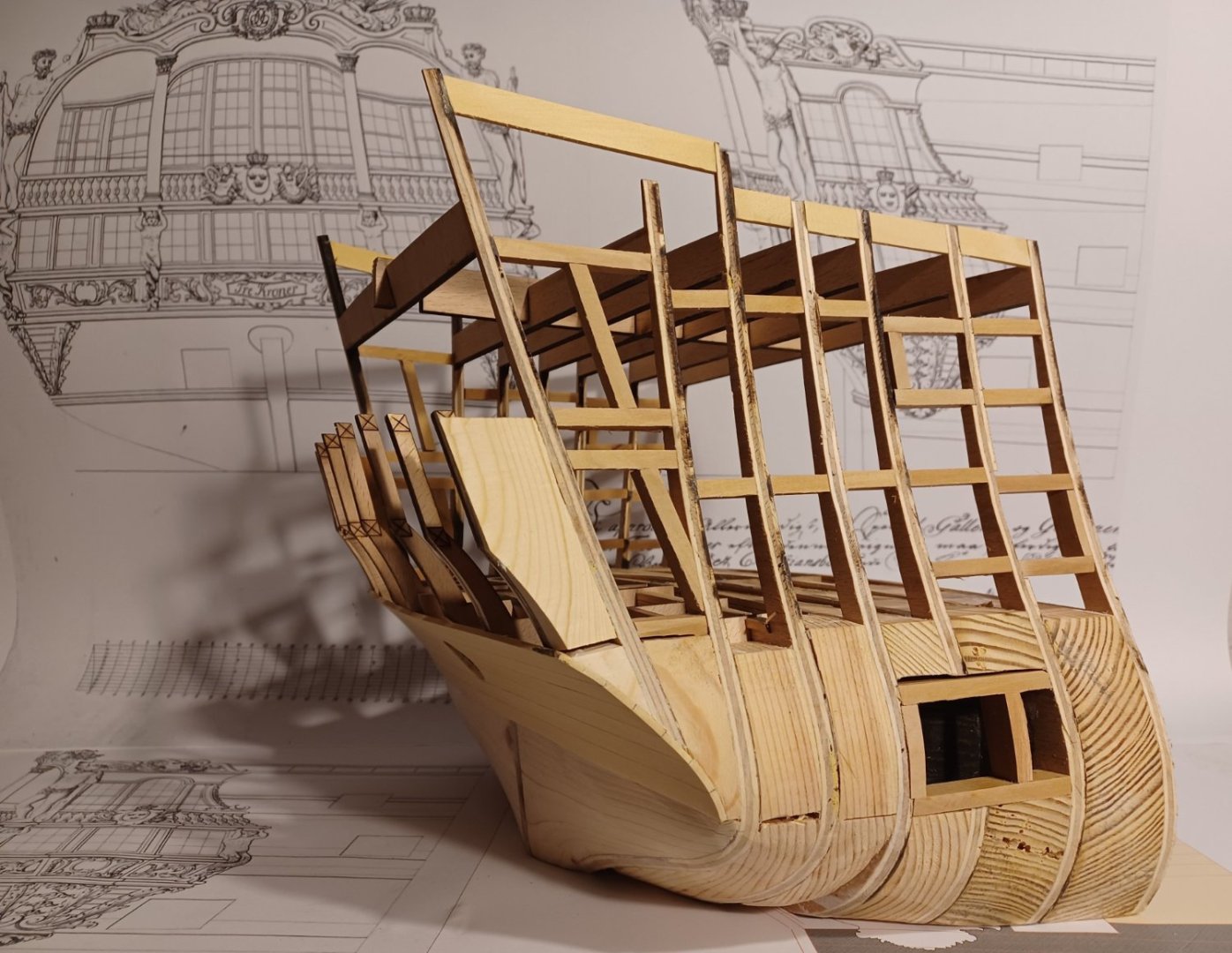
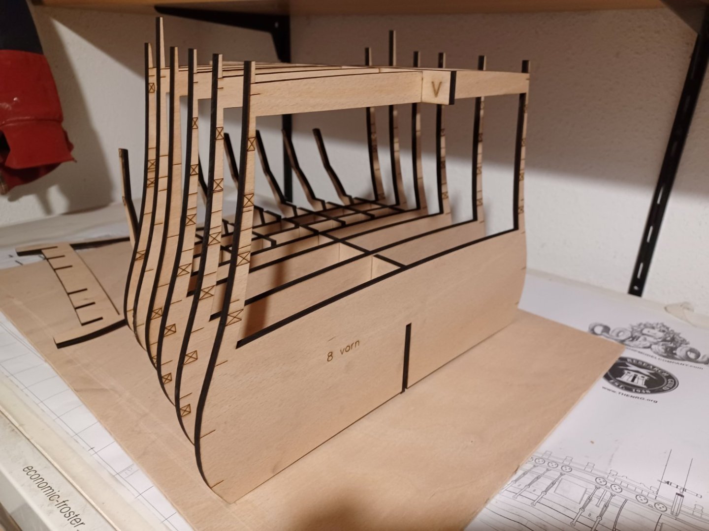
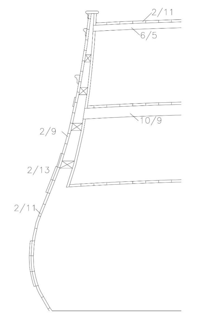
As the historical model was only used to show the stern decorations, I am focussing on that too. The hull segment itself will not be fitted with fittings, and other details but only built as correctly as possible in 1:32 scale in terms of shape, planking and gun ports. This will be the first step in finding a way to build the decorations and figures on the basis of the drawings and with the hull on the table. In order to be able to build the hull segment effectively, I prepared the plans so that the parts can be laser-cut, actually like a kit. I built a kind of height-adjustable plug-in parts for the stern, which form the framework for the lower gallery. I can adjust the height and, if necessary, the depth by widening the slots a little. The angle in relation to the vertical should be fine. The plank division was based on a comparable Orlog ship in a simplified form (one thickness, not the planking thickness decreasing from bottom to top) for the hull segment. And here the side-view of the model-section. Matthias


-
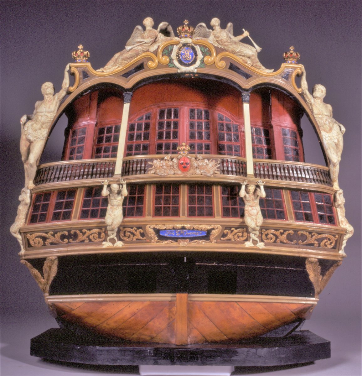
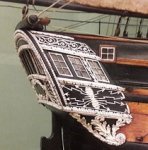
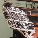
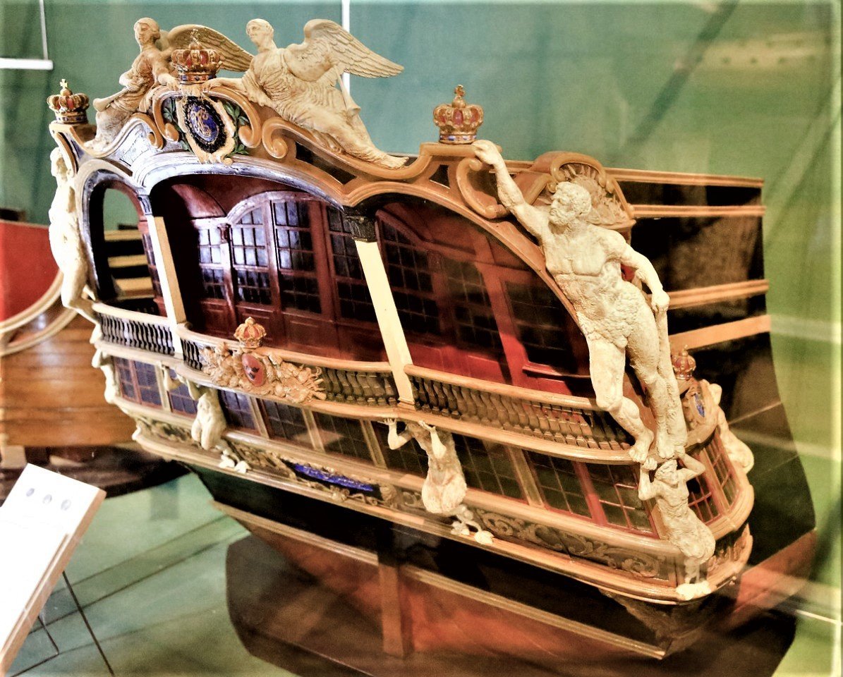
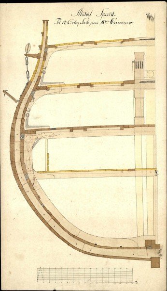
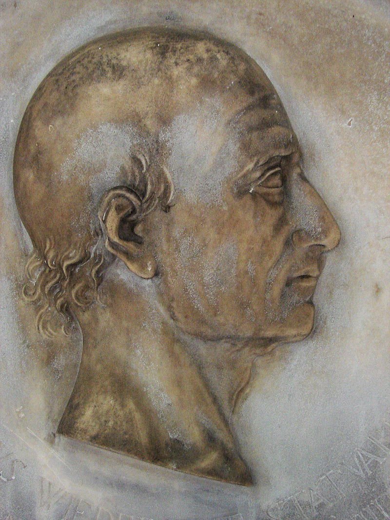
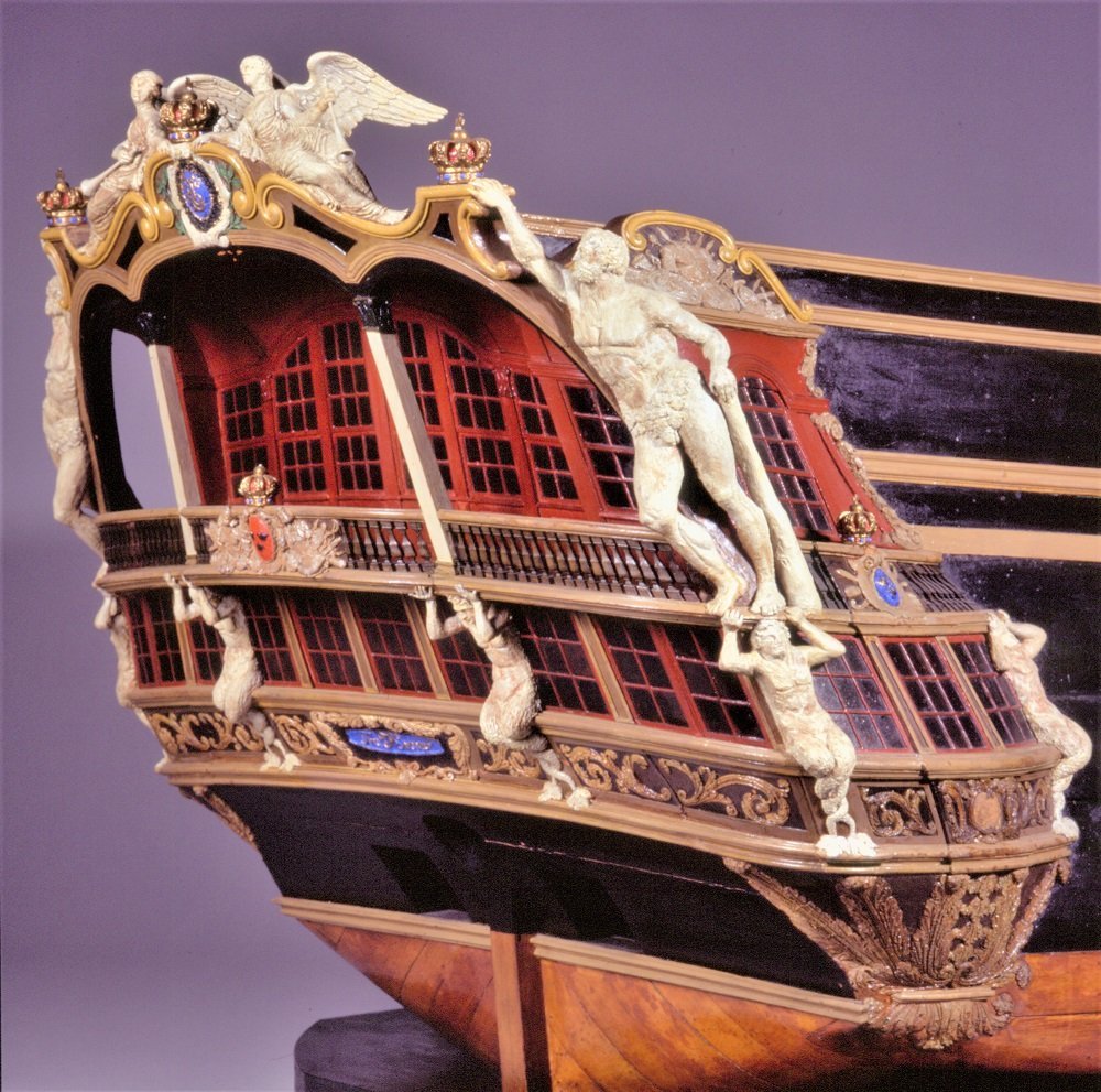
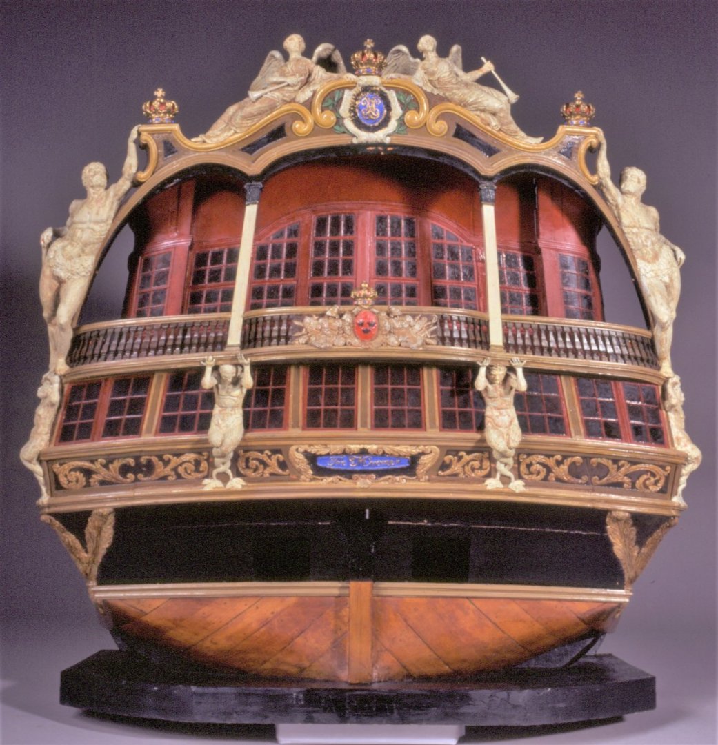
Hello everybody, First of all I want to start with some background information on my new model project, the Transom-Model of the Danish ship of the Line TRE KRONER, built in 1742. The scale will be 3"/8', 1/32. I have read some literature (source: Danske Orlogsskibe 1690-1860) about the sculptor and the shipbuilder of the TRE KRONER from 1742, which is interesting, as the ship sculptors are often unknown and the creators of the models anyway. This impressive relief by Johannes Wiedewelt depicts his father, Just Wiedewelt, who was master carver of the royal shipyards on Holmen between 1734 and 1757 and who is the subject of this work. Unlike many of his predecessors and successors, he was a true master of his trade. There are marvellous marble busts by him of the Danish royal couple Frederick IV and Louise from 1719. Incidentally, the Wiedewelt family immigrated to Denmark from the Thuringian Vogtland, more precisely from Schleitz, in his father's generation. Wiedewelt prevailed against several competitors in a competition for the post on Holmen and held the post until his death. The 1:32 scale model of the stern of the TRE KRONER in the Danish Krigsmuseet is by his hand. The sculptures are made of wax, the hull of the ship of wood. (Source: War Museum staff by email) The master shipbuilder who designed and built the TRE KRONER as a 70-gun liner was a Frenchman named Laurent Barbé (1696-1754). As far as I know, no illustration of him has survived. He was called to Denmark by the Admiral-General and head of the naval administration Friedrich Danneskiold-Samsøe, as after several scandals, confidence in the local forces was apparently so low that an Englishman or Frenchman was needed to fix it. He was appointed chief designer on 6 May 1740. Barbé seemed to have been a somewhat obscure person. Nobody knows where he came from in France or where he had learnt the art of shipbuilding. Interestingly, French naval historians have never been able to find any information about him in his home country. From the very beginning, there were difficulties in the co-operation between Barbé and the Danish design commission, which had to supervise the shipyard's operations. Barbé had accepted his appointment on the condition that he would not pass on his design methods. When he was finally asked to explain his construction method, Barbé explained that he had been promised that he did not have to reveal his method and that knowledge of this method was not necessary in order to build according to his drawings, and that he "did not want to publicise what is precisely my science and art, because if it became known, every shipbuilder could do the same as me, which would be one of the most miserable events as a foreigner in a country". It is well known that in several cases he used French drawings, which he could hardly have made himself; he apparently simply tried to adapt French designs, which he had at his disposal, to Danish conditions. In 1744, for example, he was asked to draw a galley. He then submitted drawings that had to be changed, partly because the benches for the rowers were designed for southern Europeans, whose average height was smaller than that of northern Europeans. He was finally dismissed in 1747. He had married in Copenhagen and therefore remained in the city, where he died in 1754.
-
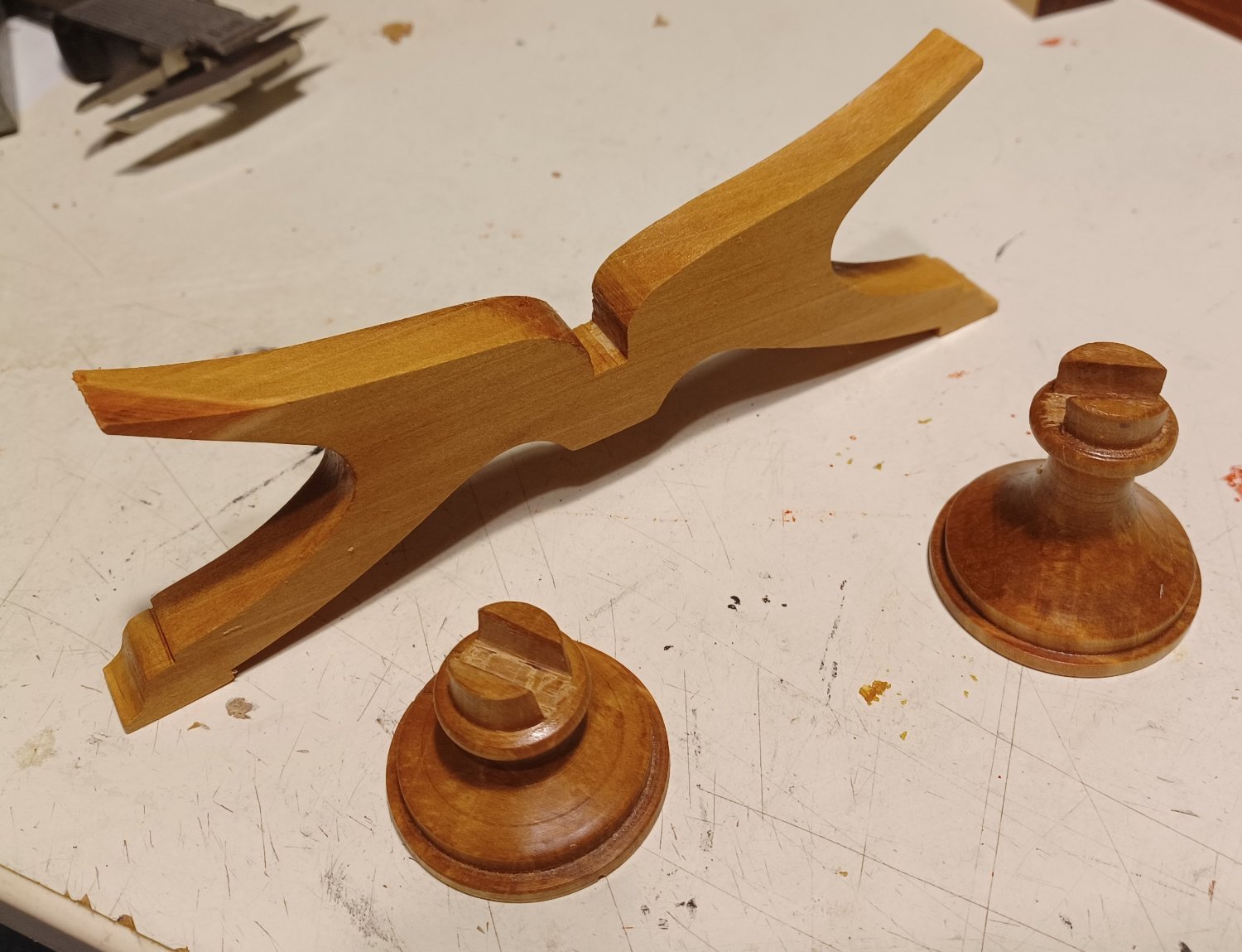
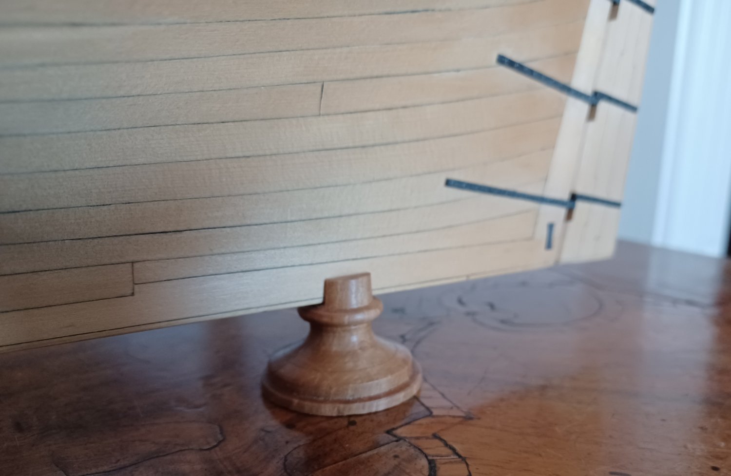
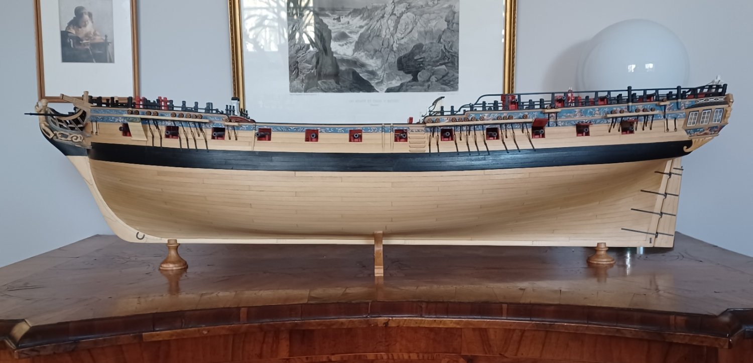
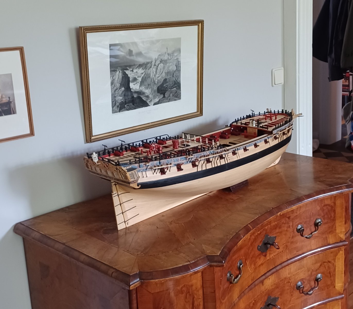
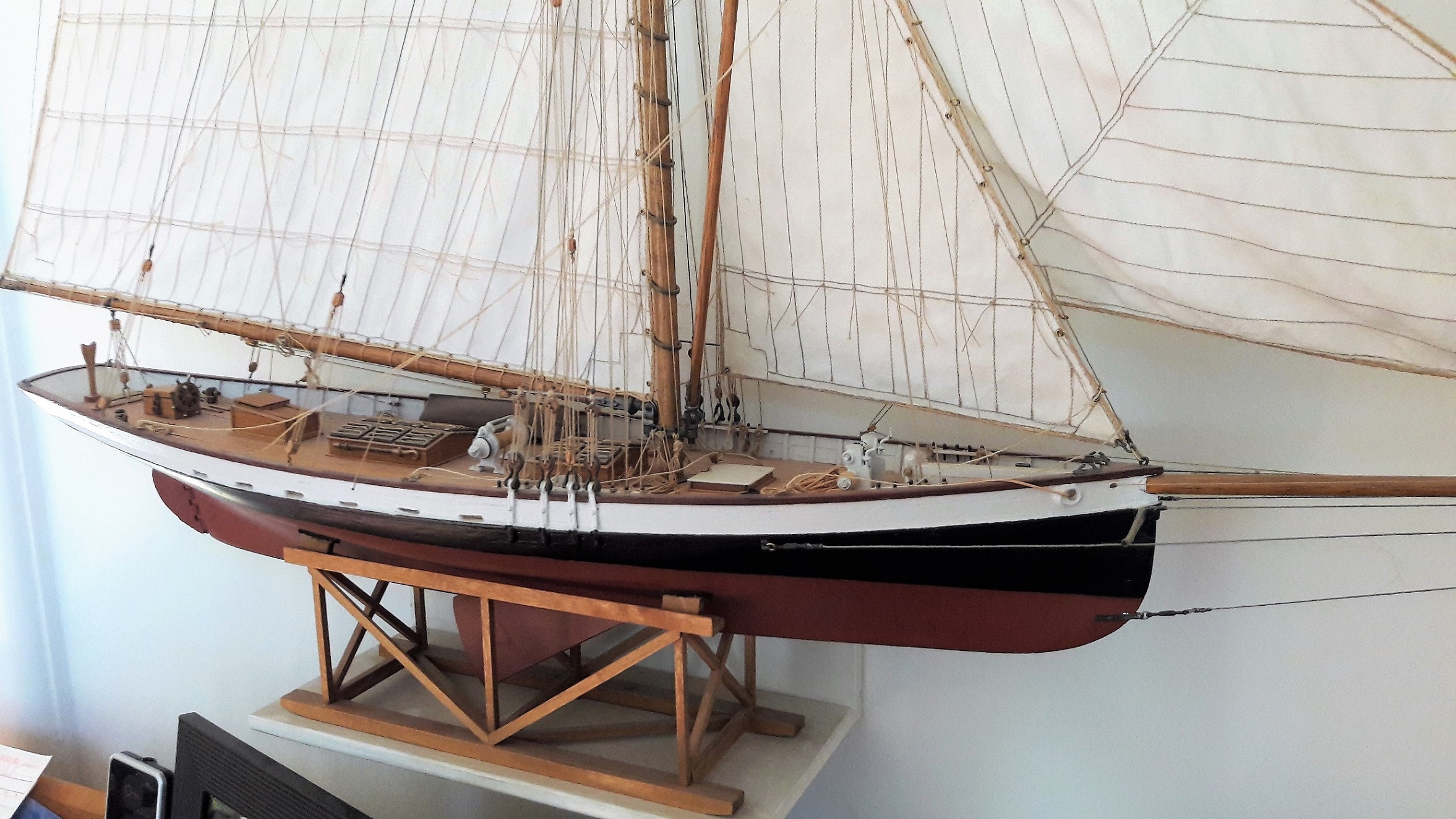
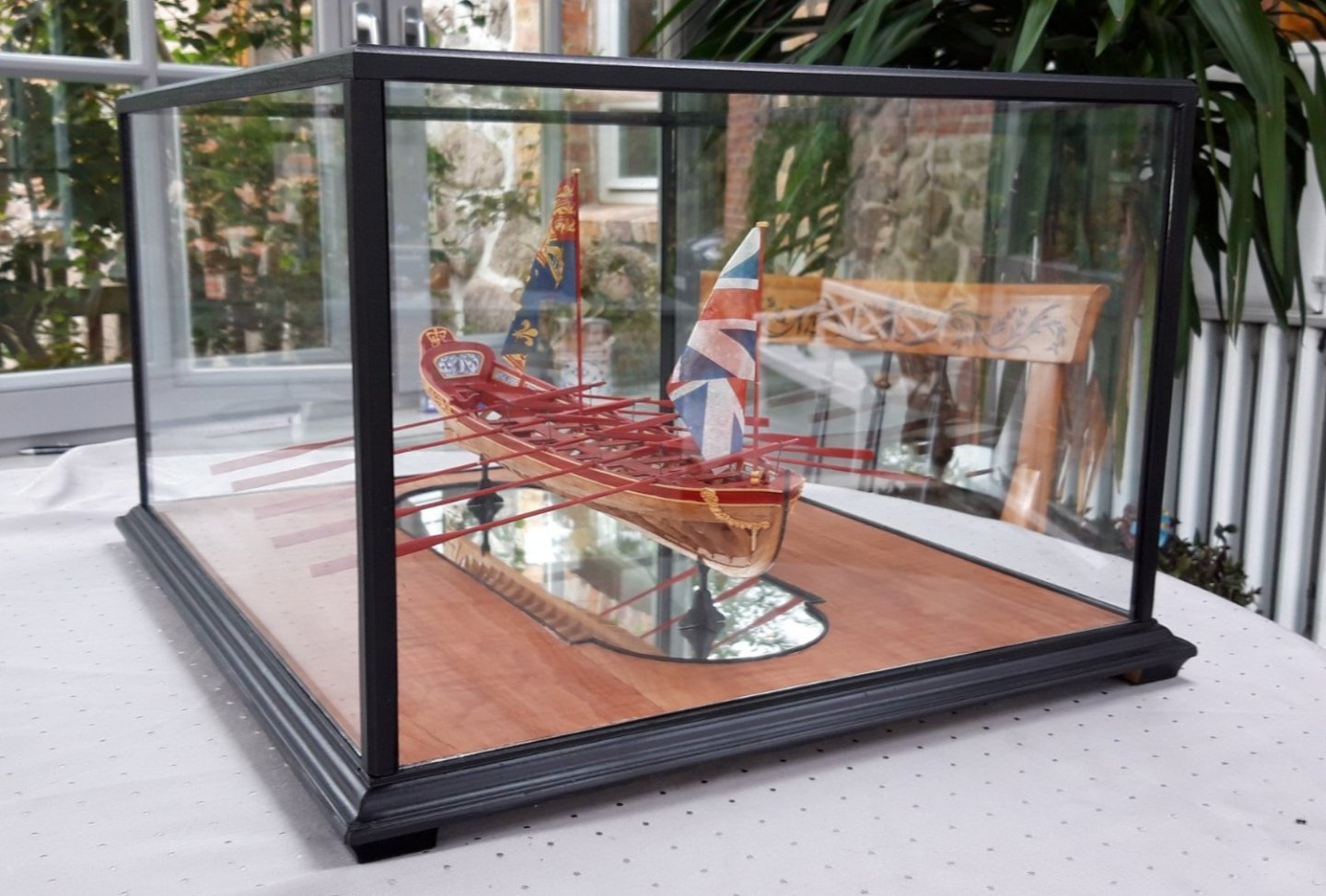
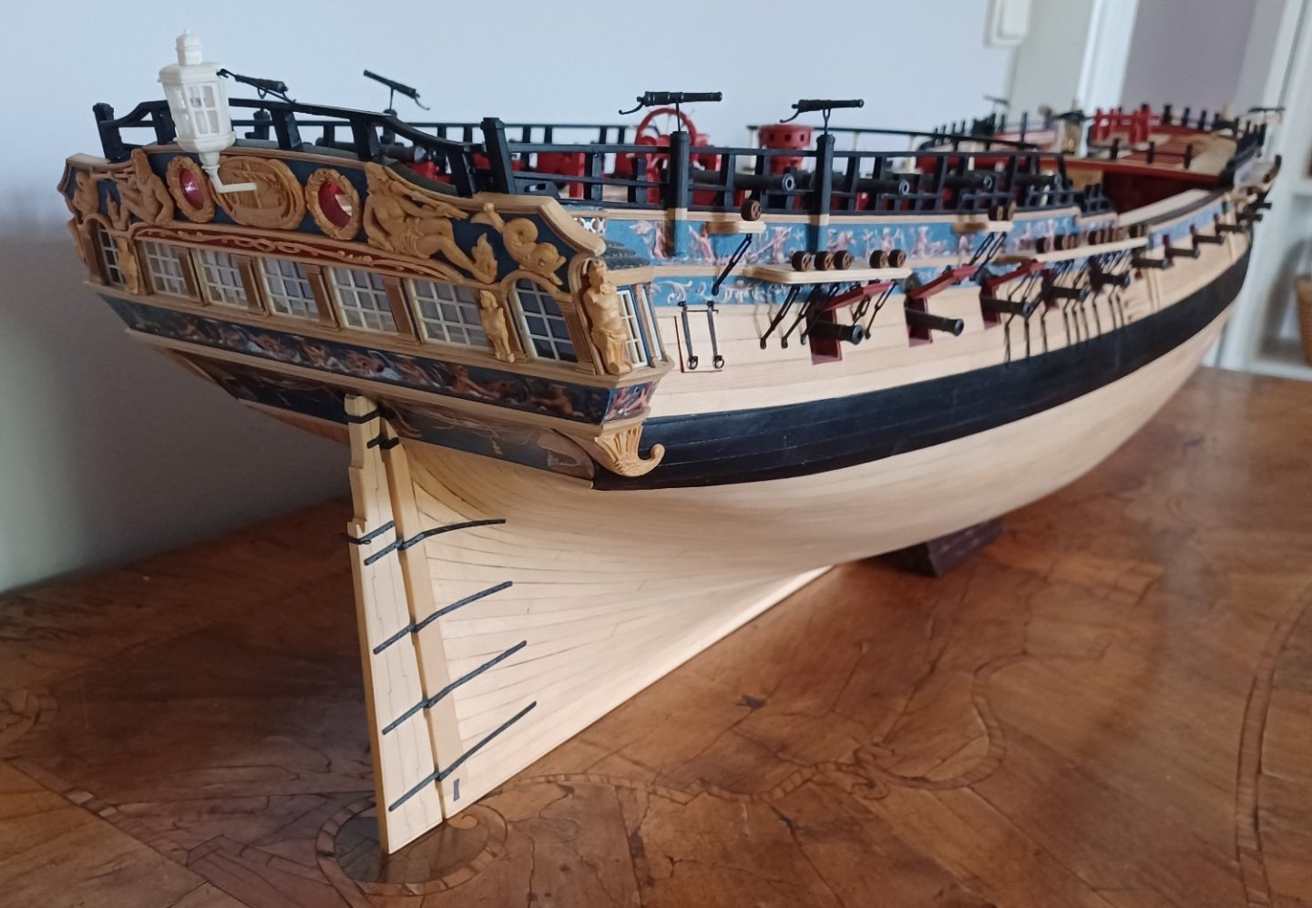
Hi Everybody, my display case is still not finished, but I managed to make some progress with the stand. I saw, that many displays have the model parallel to the keel, my model will be sitting parallel to the waterline. There will be two collumns, one at the bow, one at the stern wich have a different length to get the balance. Here are some pictures: Matthias


-
Hi Chuck, one question: Did you make the Winchelsea display-stand parallel to the waterline or parallel to the keel? The Amazon display is obviously made parallel to the waterline, the bow column is longer than the one at the stern. Thanks Matthias
- 1,784 replies
-
- 1
-
-
- syren ship model
- winchelsea
- (and 1 more)
-
Thanks Frank
-
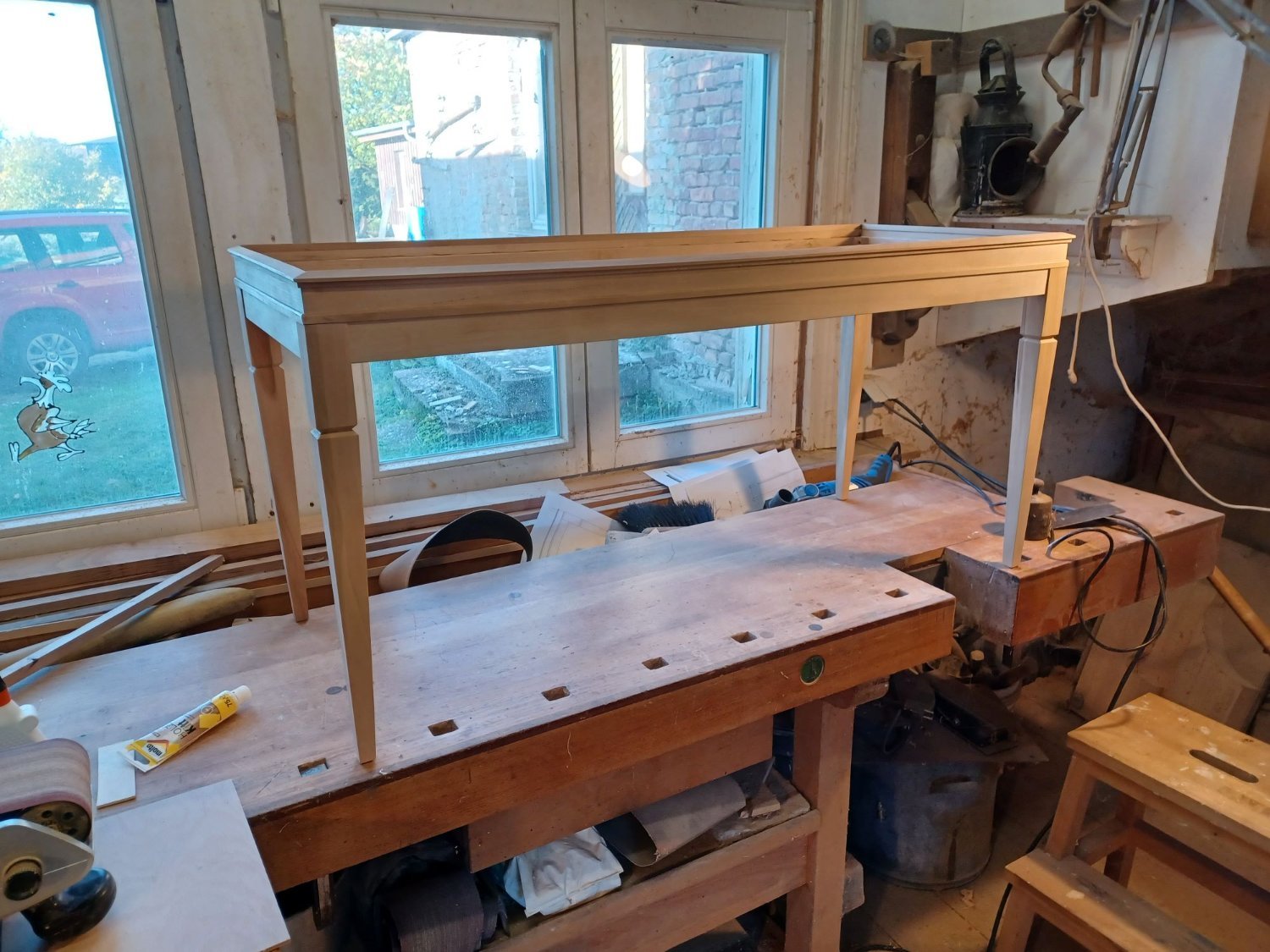
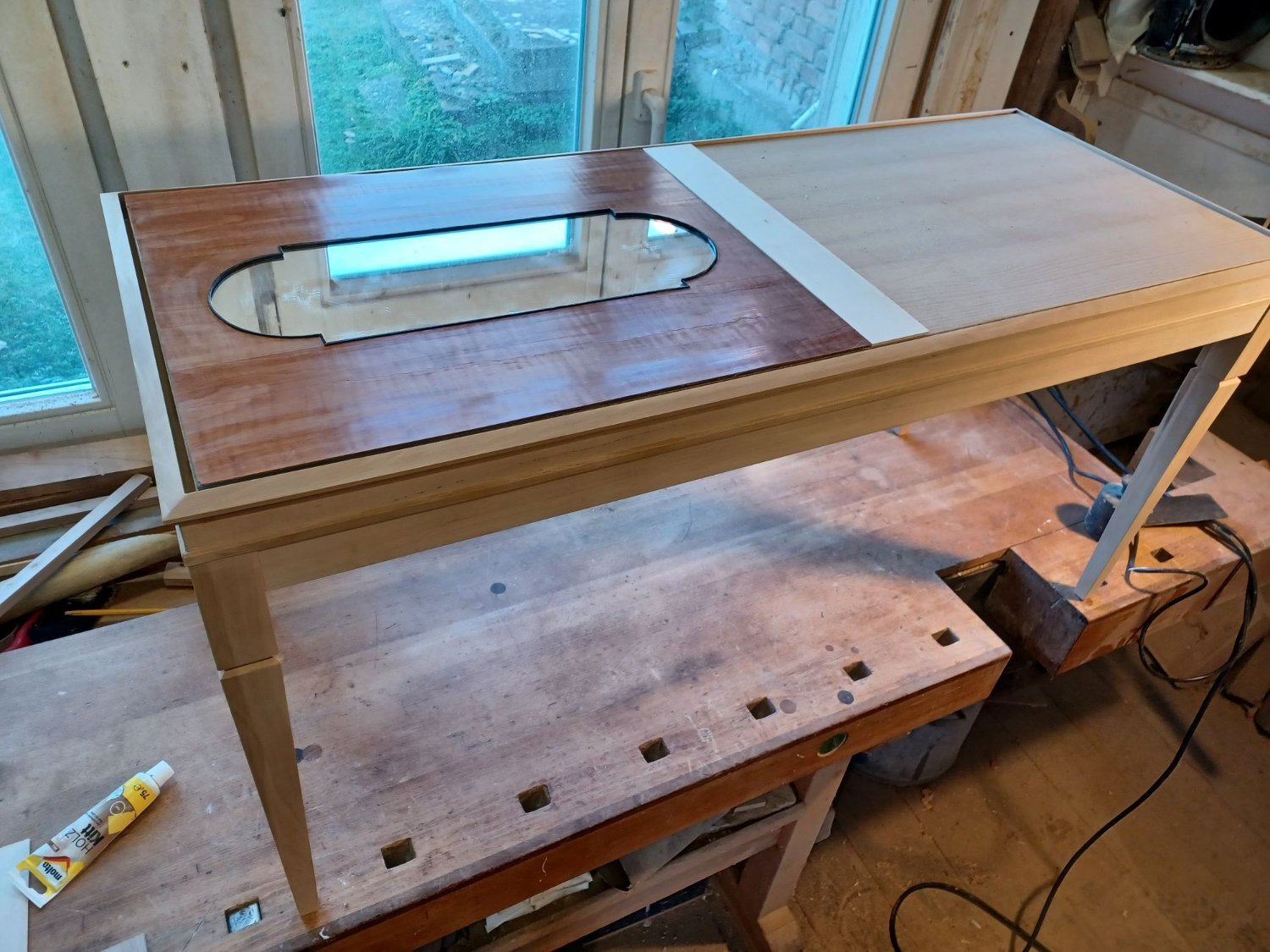
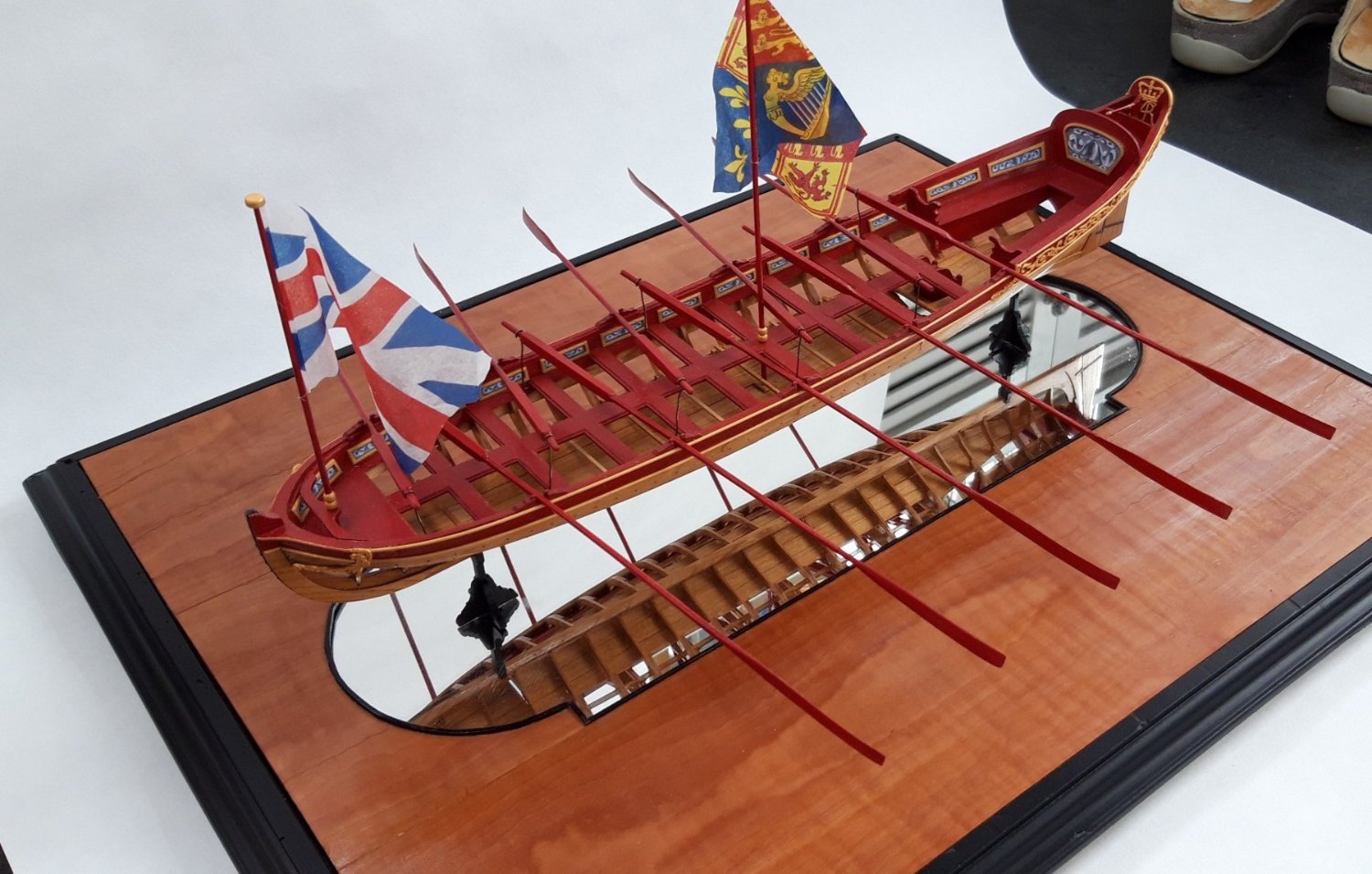
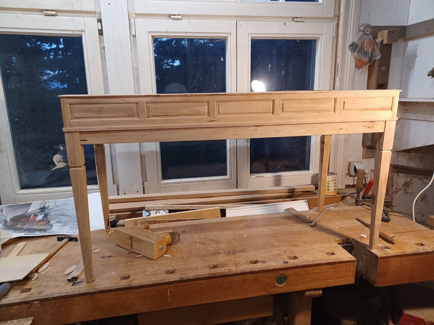
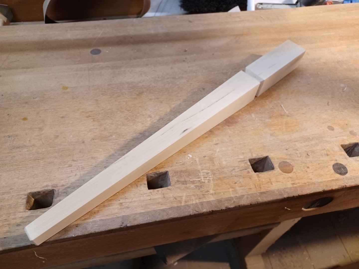
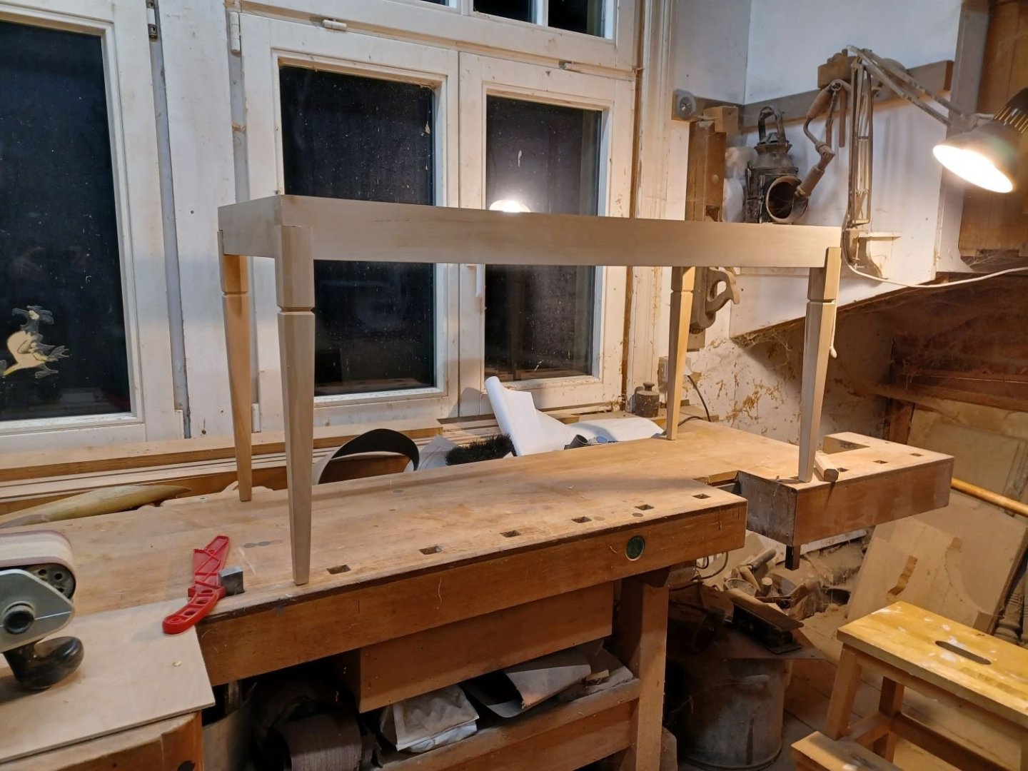
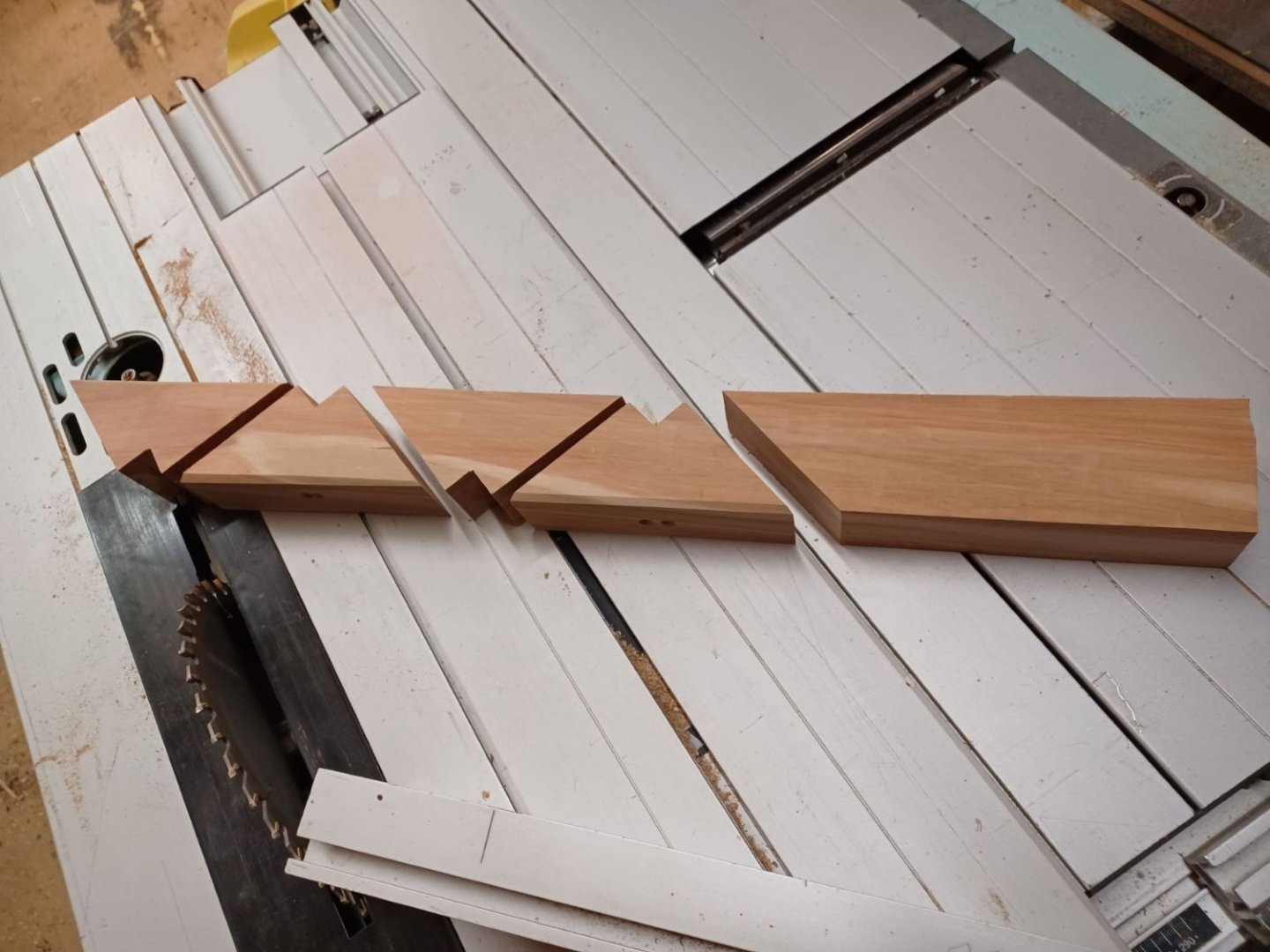
Thank you all for the comments and likes. at the moment I am working on the dispay case. As I showed above, I want to make a case for three models. My Queen Anne-barge 1"/2' scale and my bone model of the azorean whaleboat wich I showed in my other build log on MSW, also 1"/2' scale. They will be together in the "ground floor" and above them the Winchelsea. Last year I cut a pear tree and so I have some nice pearwood for the case. by now it is dry enough and I started on the table of the case. I started with the legs for the table, dimension 40/40/400 mm Then the table was put together... some parts to stiffen the construction in the corners... Some strips to cover up the top... Here ist one of the models for the ground floor, the mirror-basement will come into the display case as well. Matthias


-
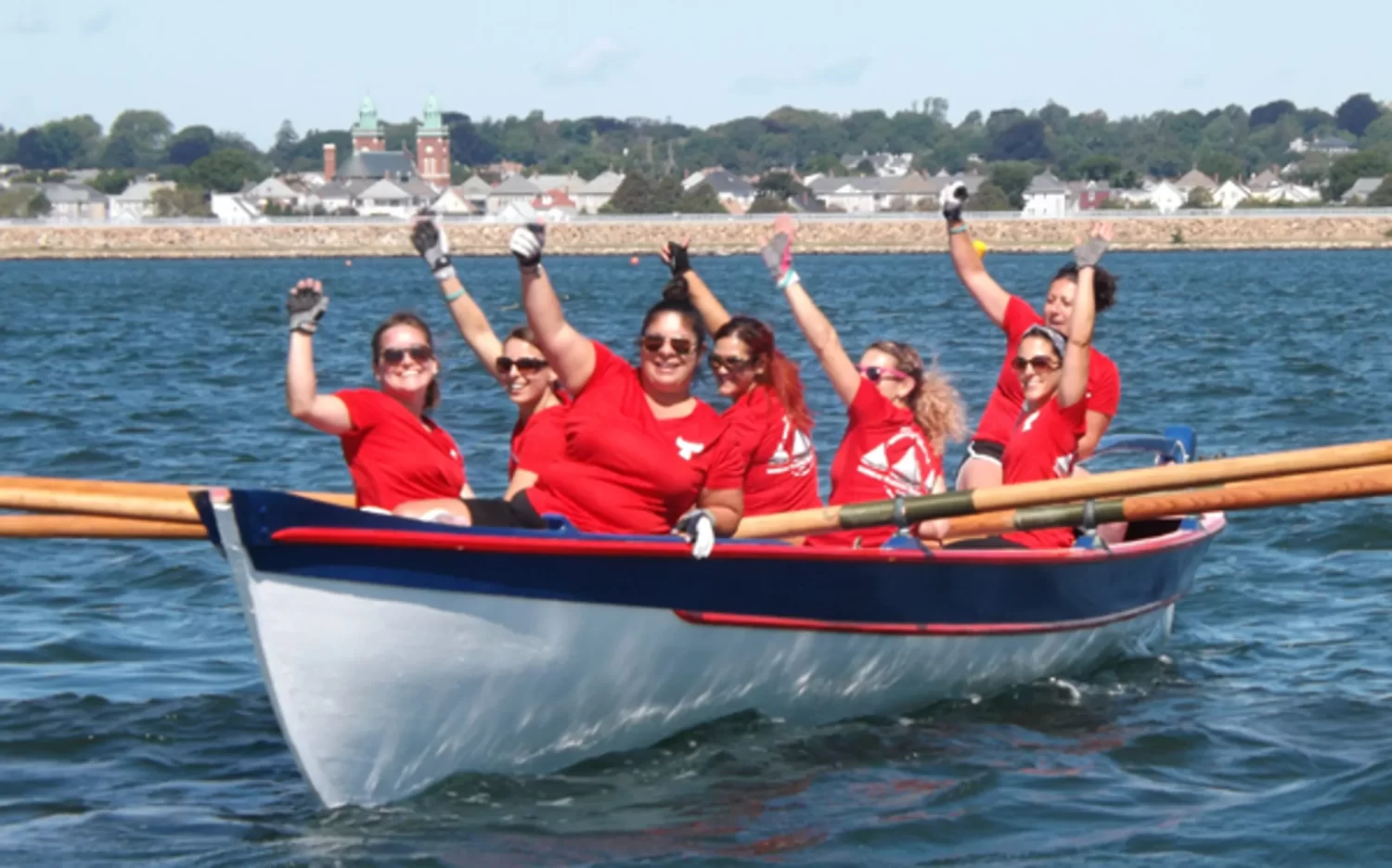
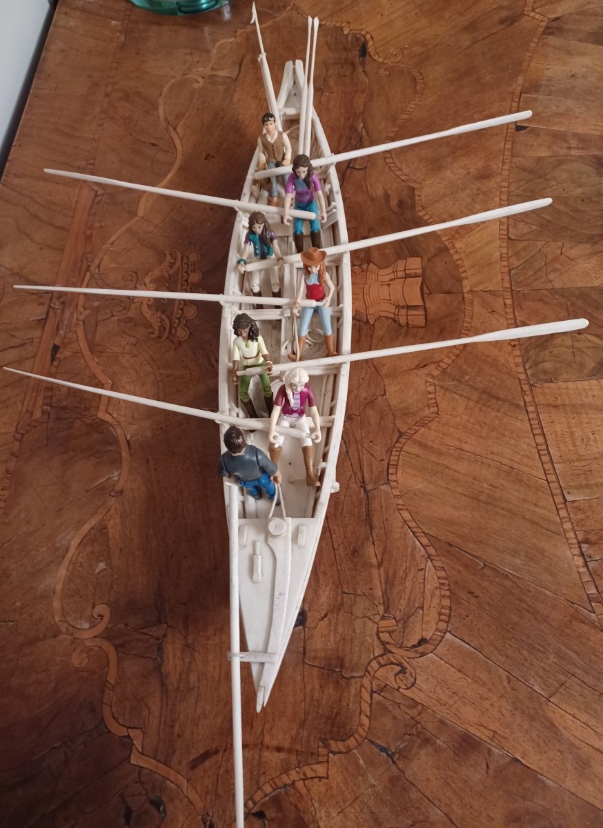
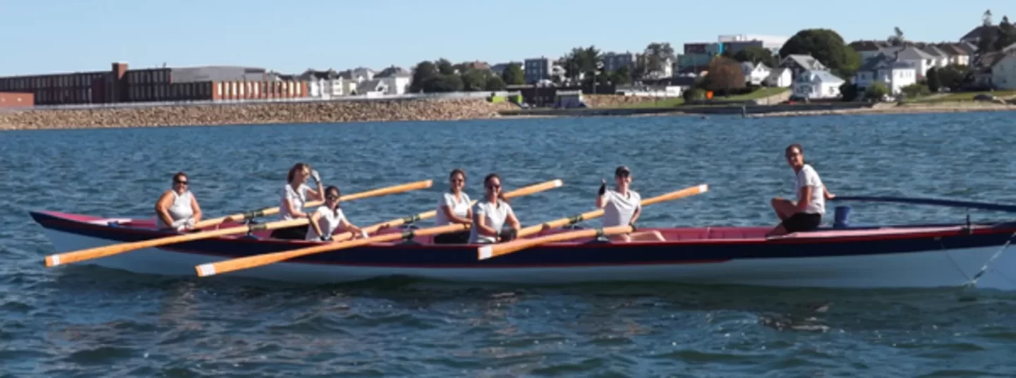
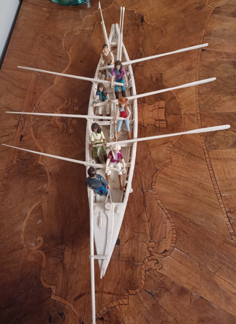
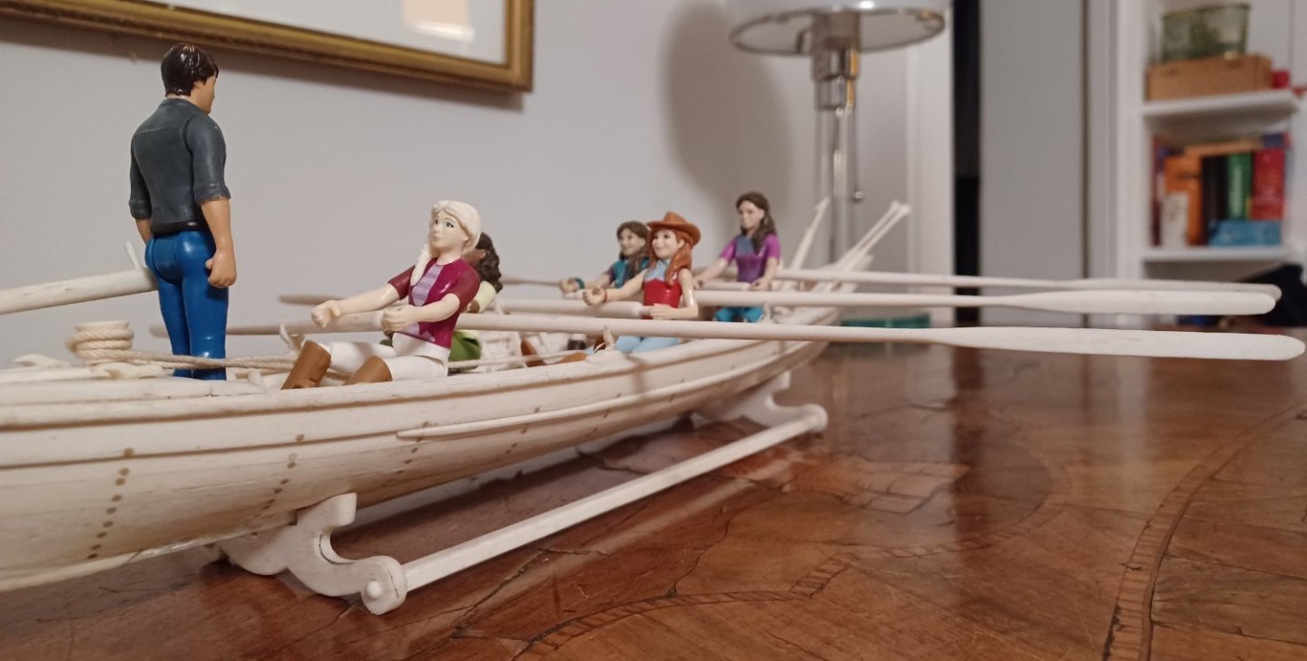
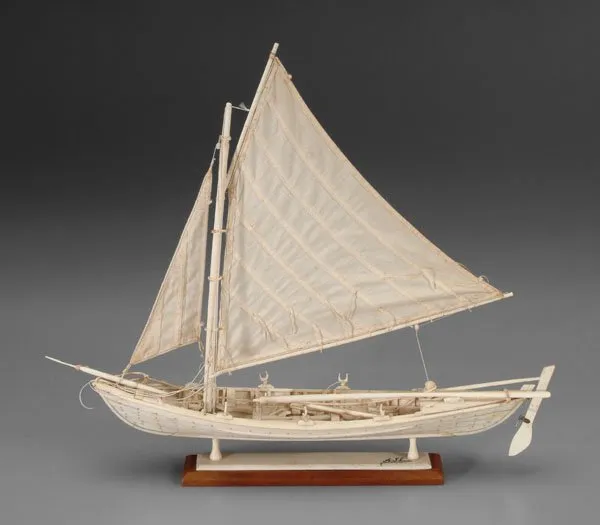
Thanks druxey, here my inspiration for the crew: nowaday they still build these boats for touristic and sport events. They sail regattas and row them. There are lovely photos on the internet I am married and we have 5 daughters, so guess, what I am dreaming of... Matthias That

- 7 replies
-
- 3
-
-
- whaleboat
- restoration
- (and 2 more)
-
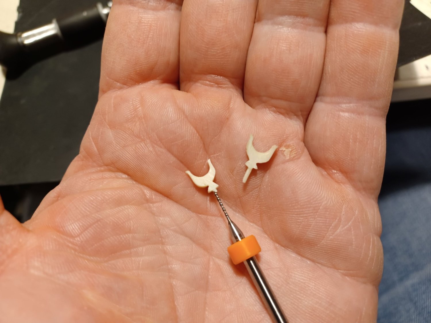
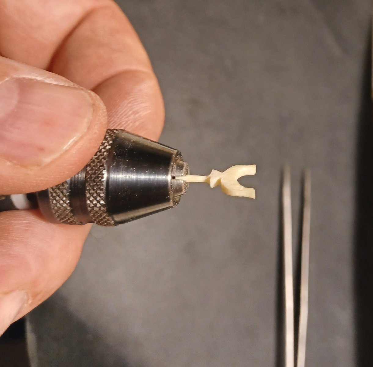
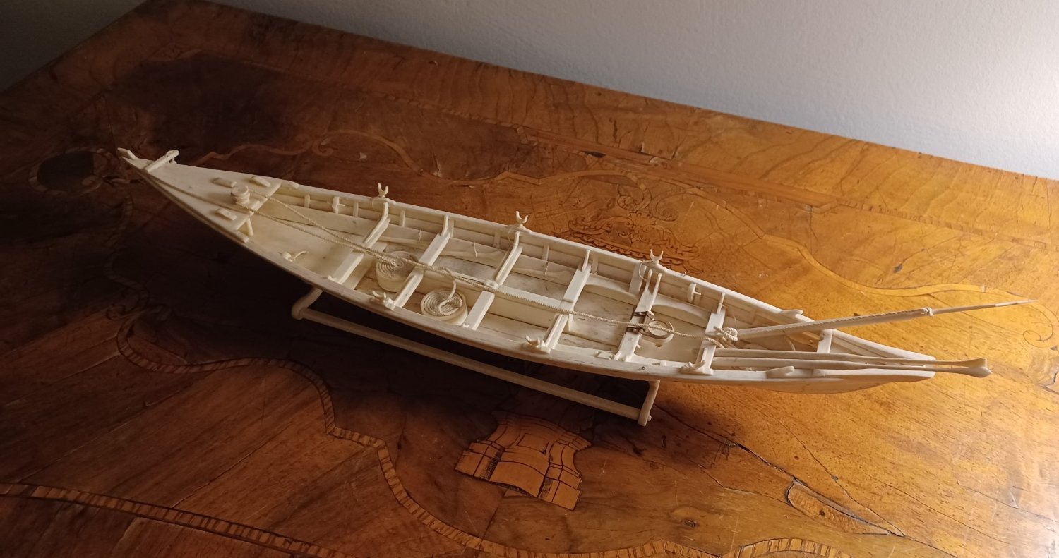
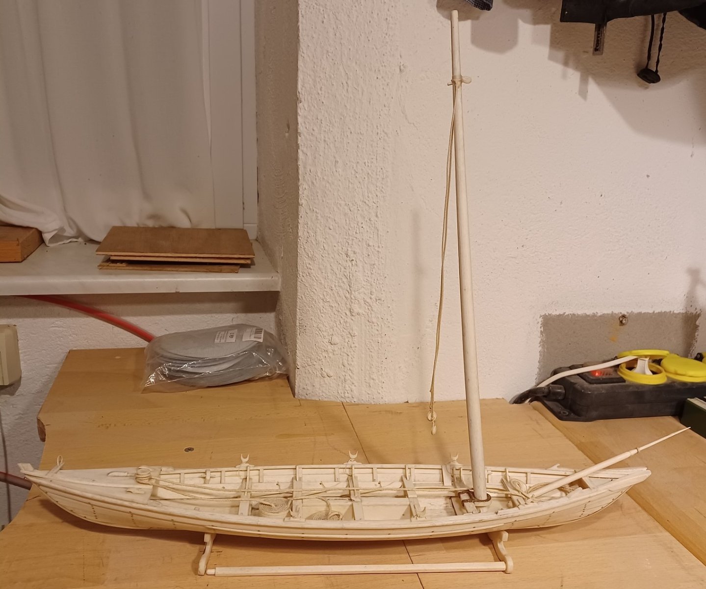
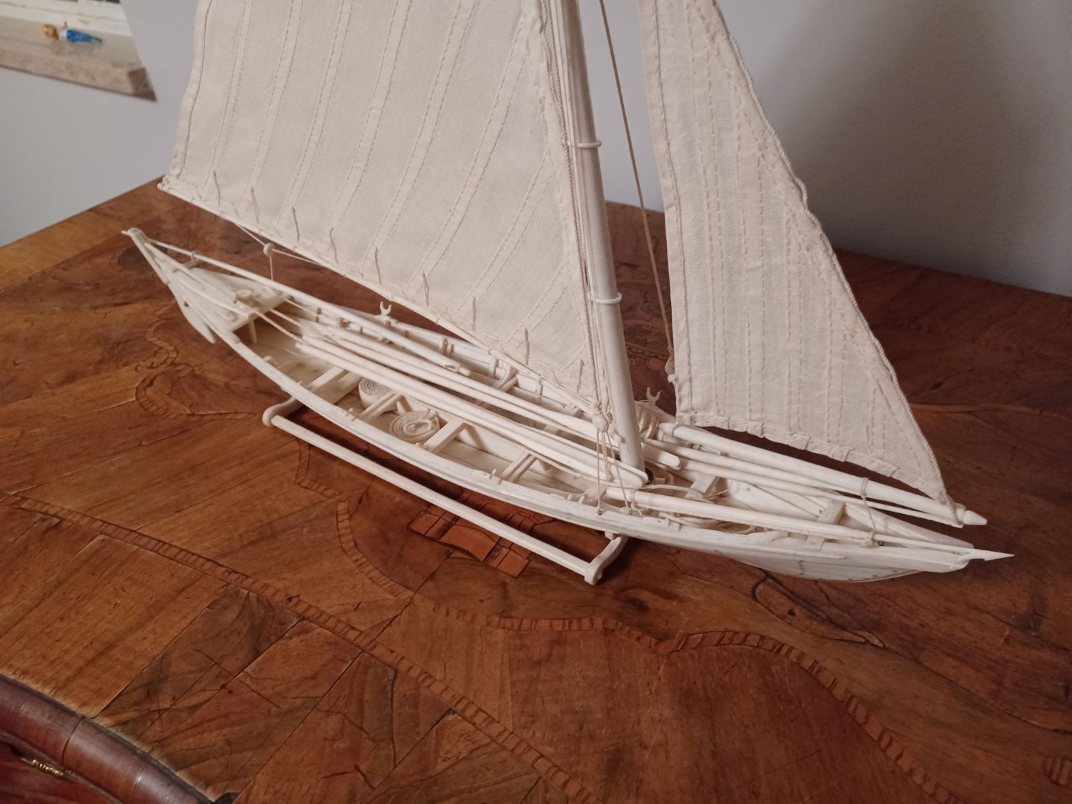
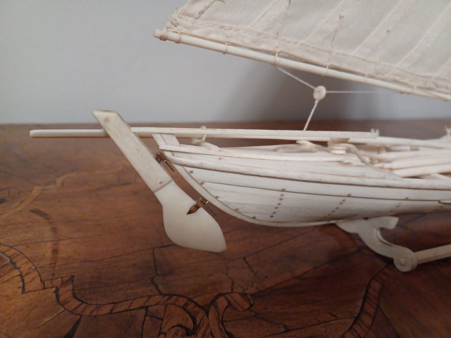
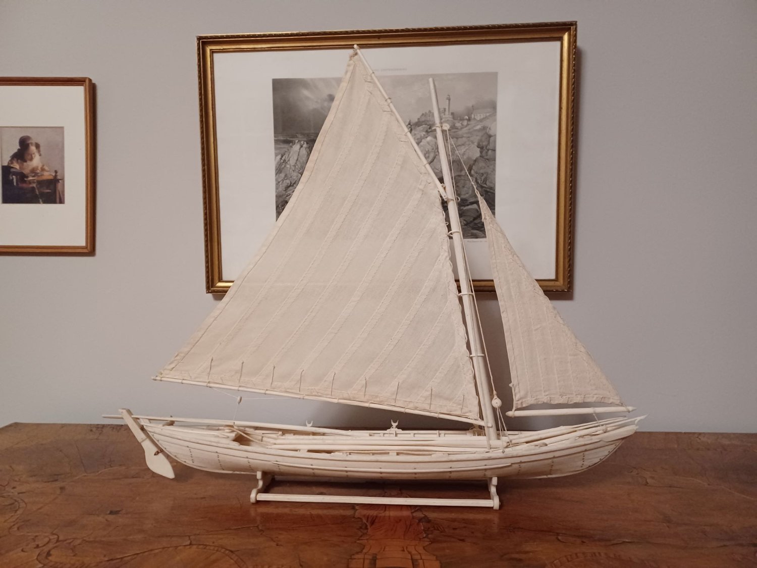
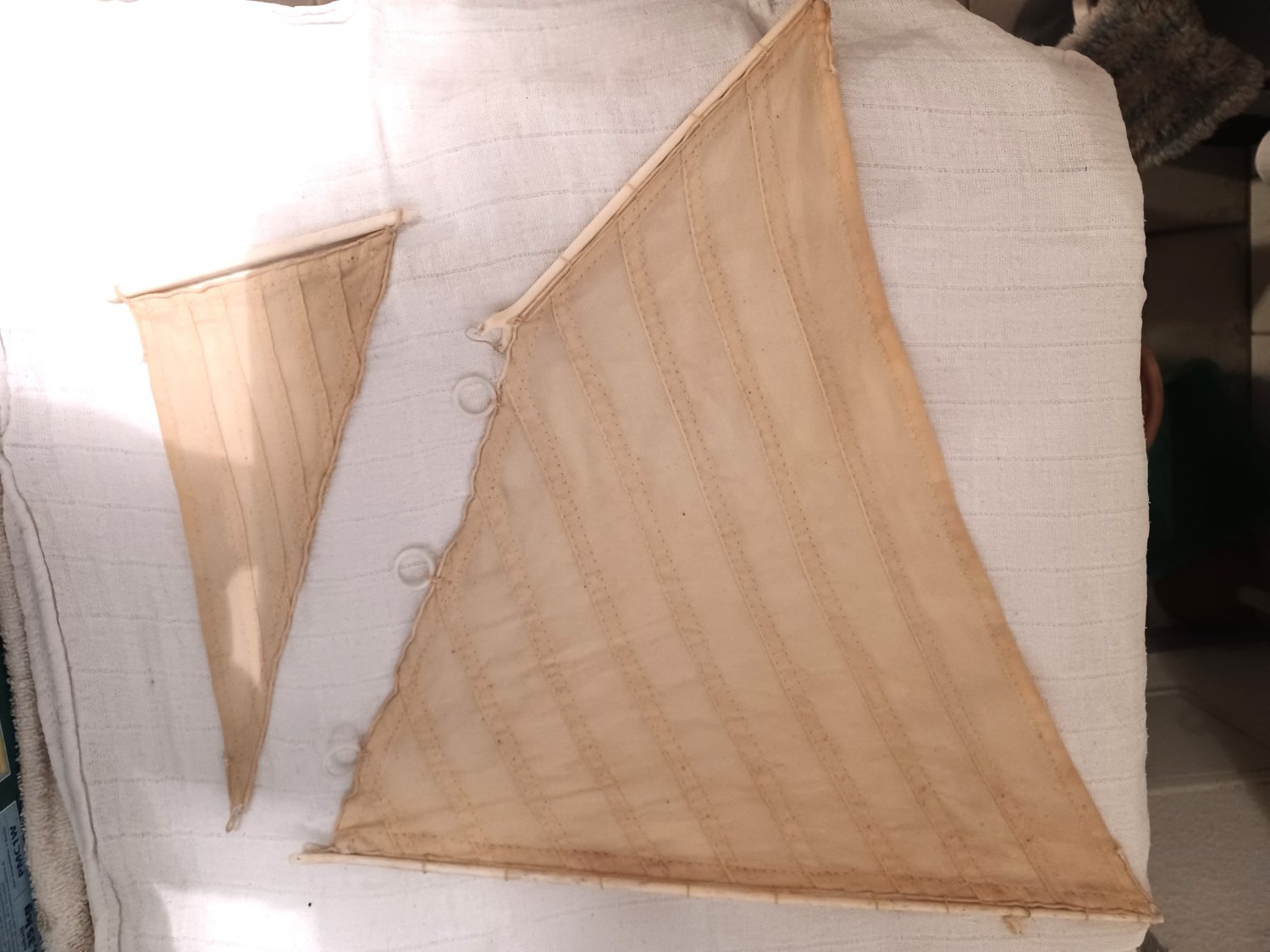
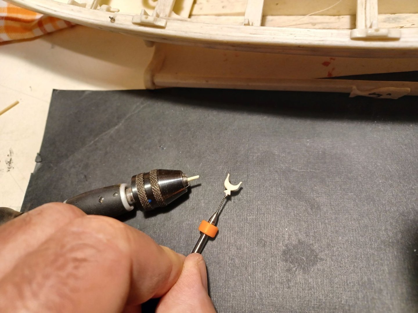
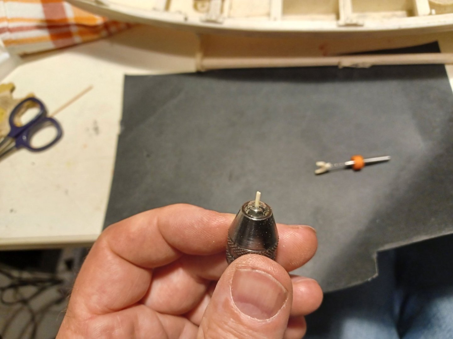
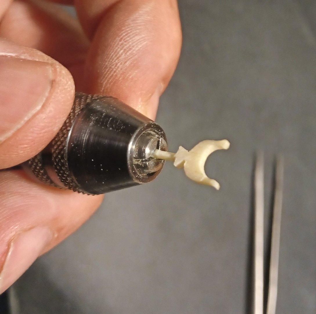
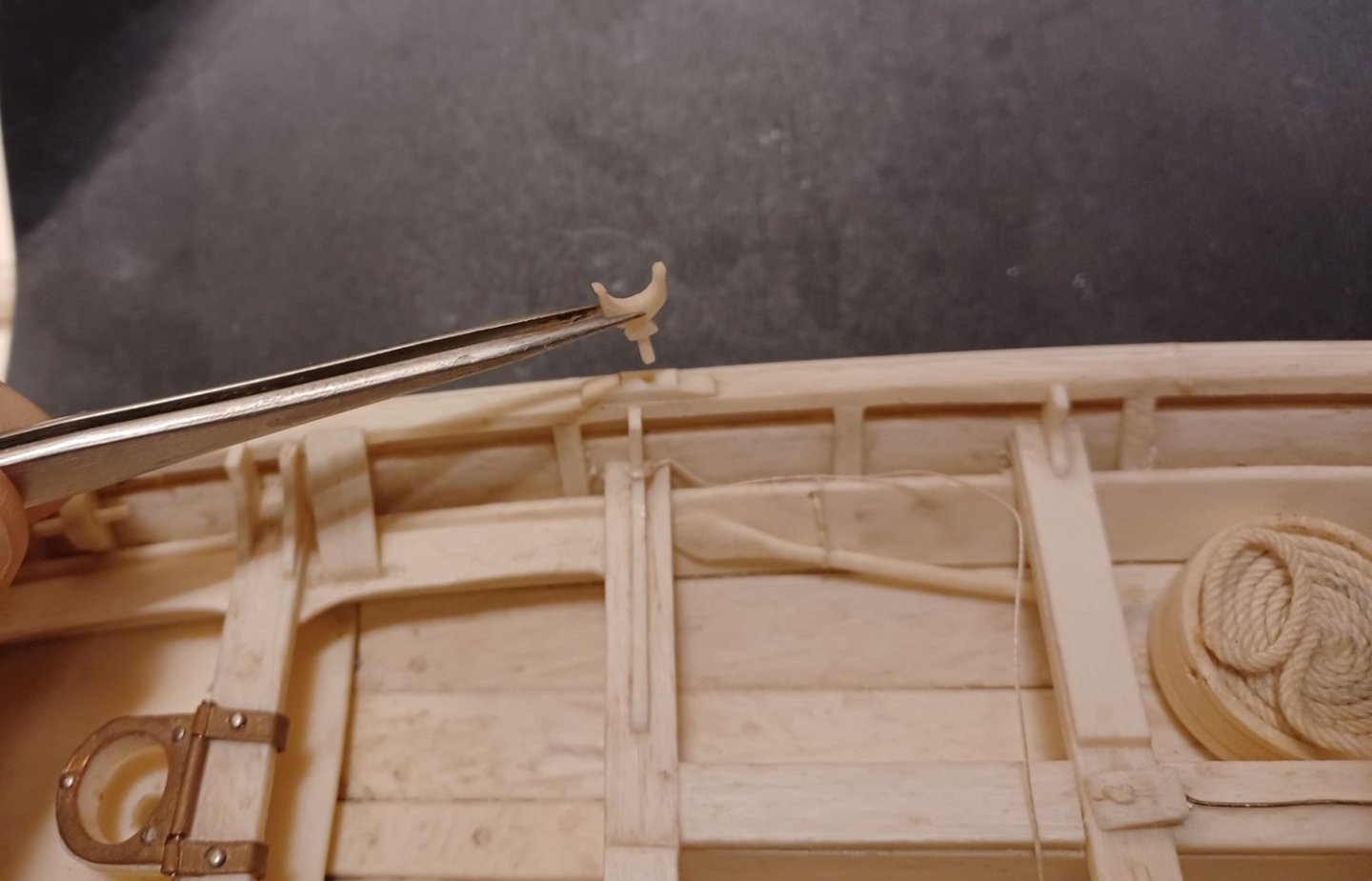
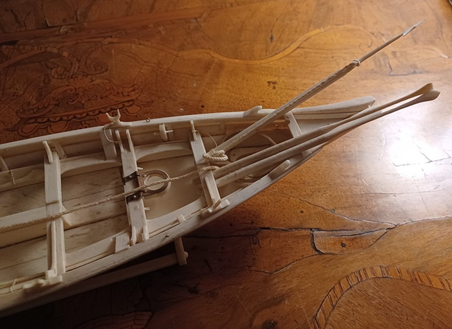
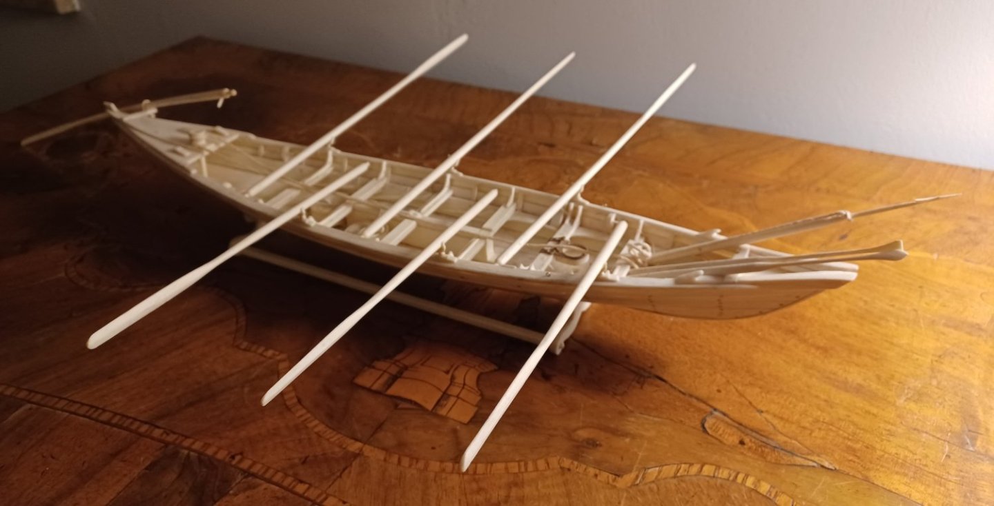
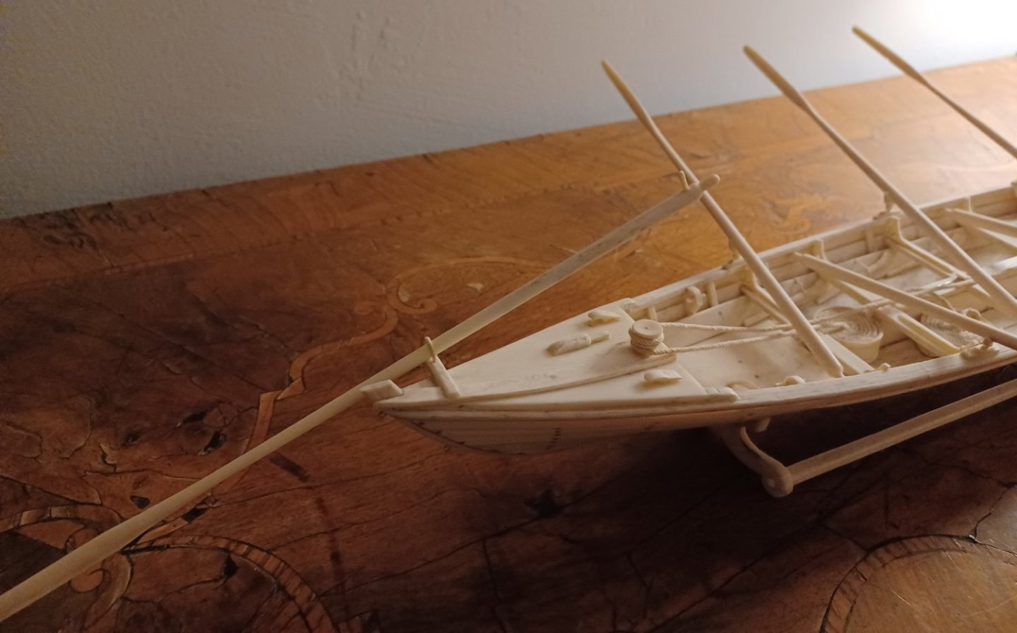
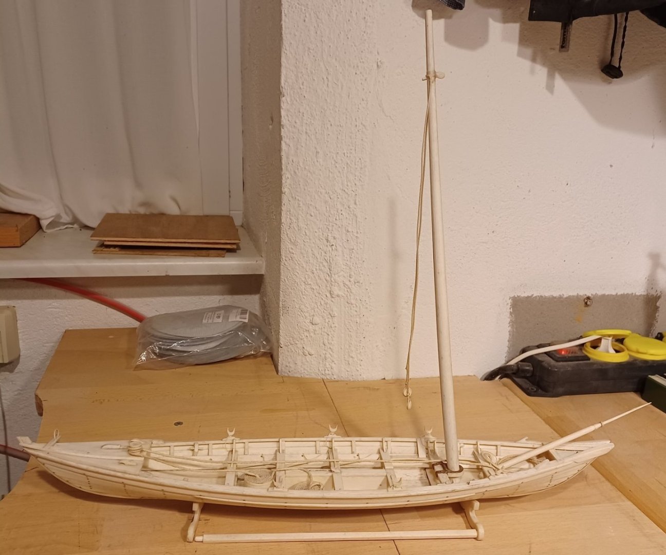
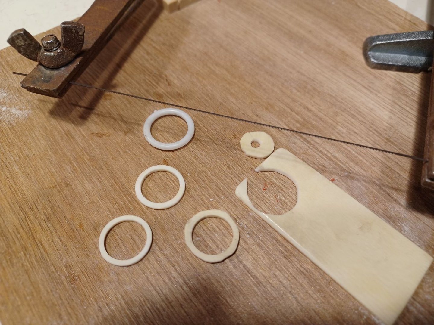
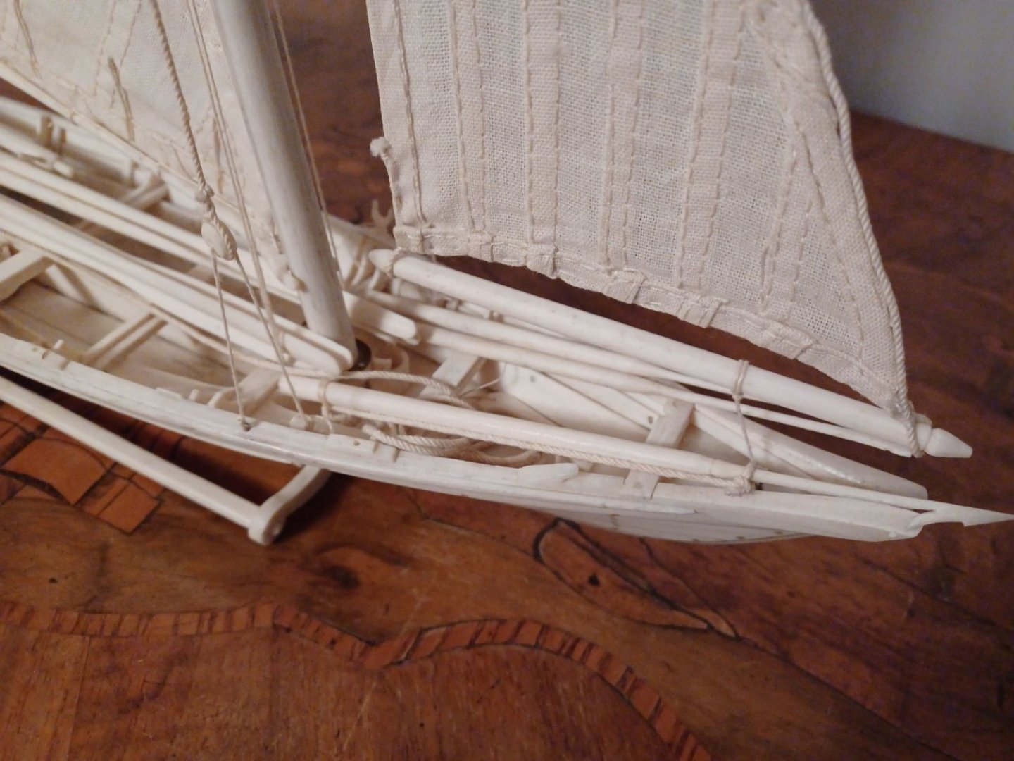
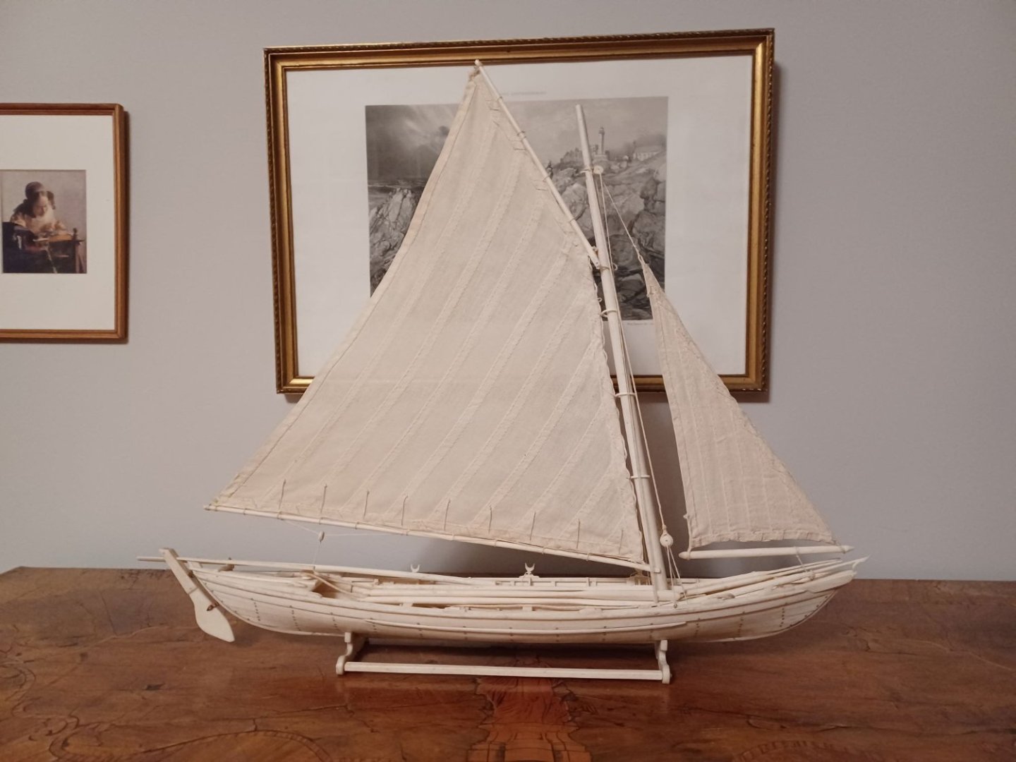
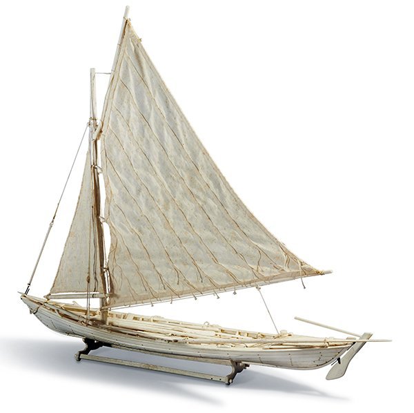
Hello Everybody, my little whaleboat-project continues. First of all I had to repair a broken thole. I repaired it by replacing the pin with a new one I made from bone. Here we go... After this litte work, the boat is ready for being rowed by a crew of 6 oarsmen and led by the master on the rudder or the steeringoar. I asked my daughter to help me out with a crew, so I can get an imagination of the whole thing in action. That was fun for the both of us. The model is actually very sturdy. No fragile parts. It has much of a toy, perhaps it once was made to play with? I don't know. I proceeded with the rigging. It is a very simple rig. Once the mast stands upright in his bracket, you only have to fix one shroud to each side and thats it. I renewed the mast-rings, becaus they were from plastic and looked very cheap. I made new ones from ivory. After having washed and ironed the sails, the whol rig came together. A very elegant model, I must say. Matthias


- 7 replies
-
- 12
-
-

-
- whaleboat
- restoration
- (and 2 more)
-
Hi Chuck, in my opinion, the costs of a single chapter are more important than the total cost of the whole model. I never counted together, what I payed for all the chapters of the Winchelsea, because it does not matter. But I always had a look on the price of the next chapter + tax + delivery. So for most of the people it is probably best to not make a chapter more expensive than 250 to 300 $. You probably need 750 to 850 $ for the framing, so you better make 3 chapters for the framing and there will be many folk able to afford it. I am shure, everybody wants to build this model. Matthias
-
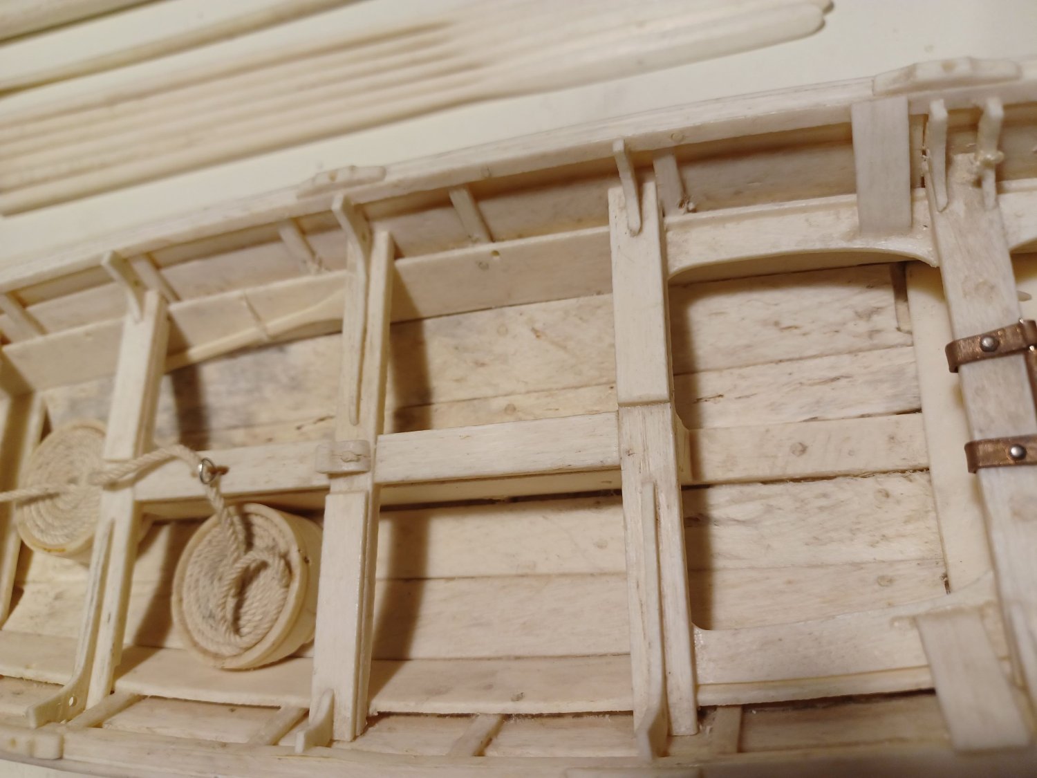
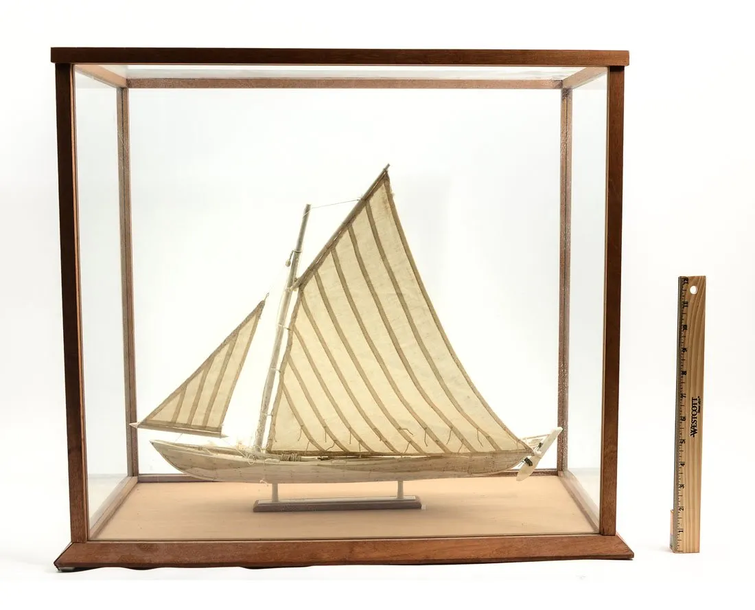
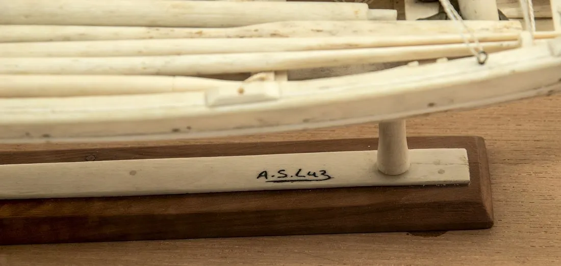
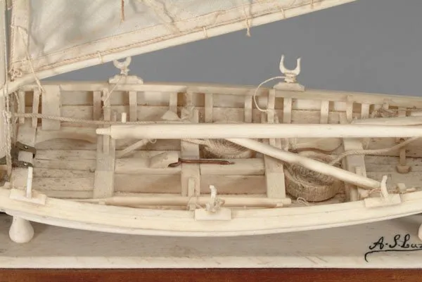
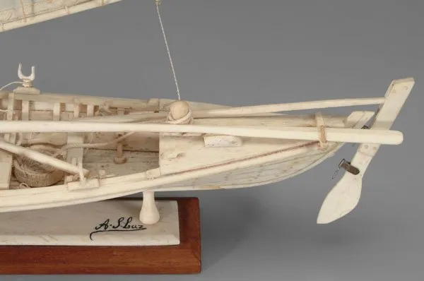
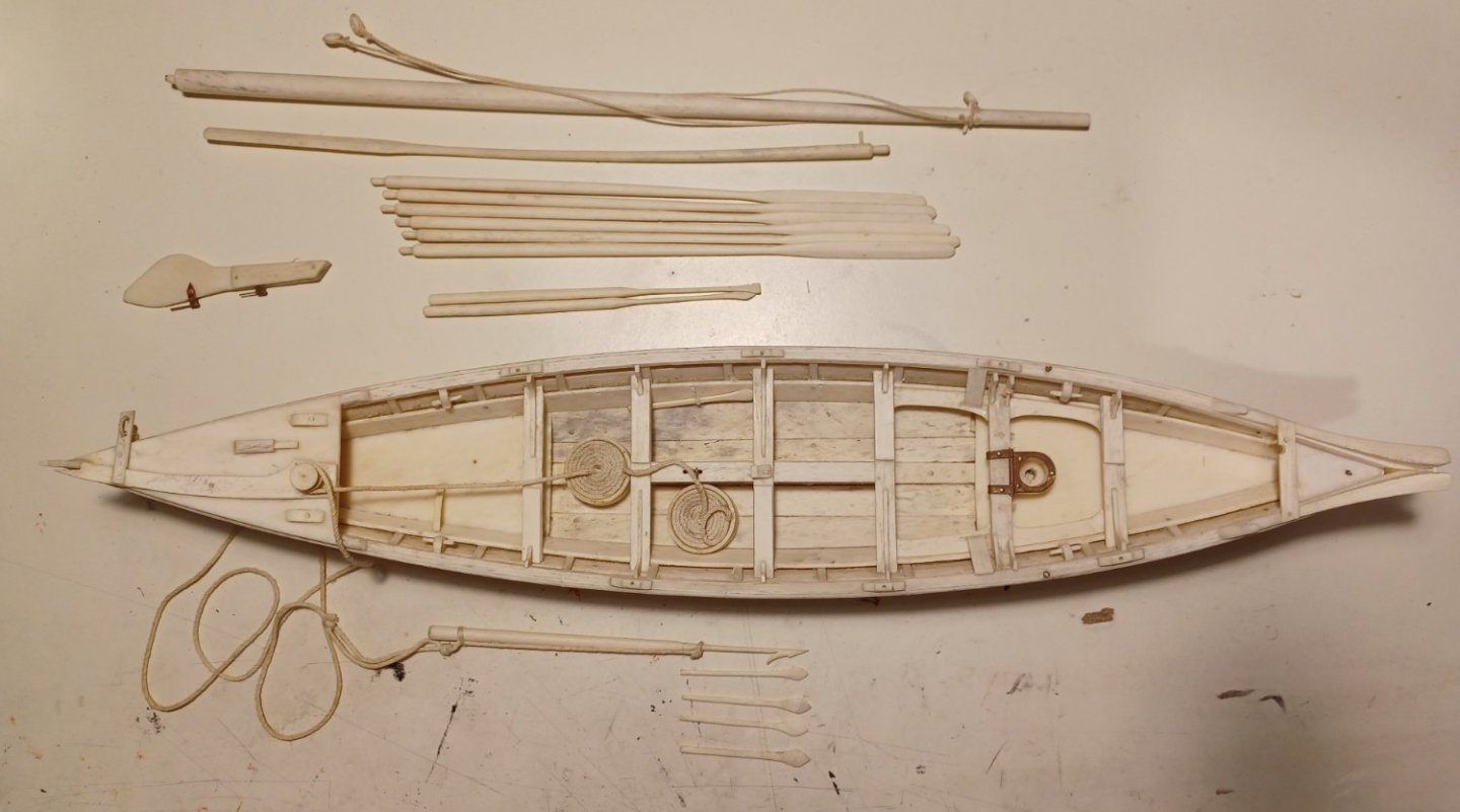
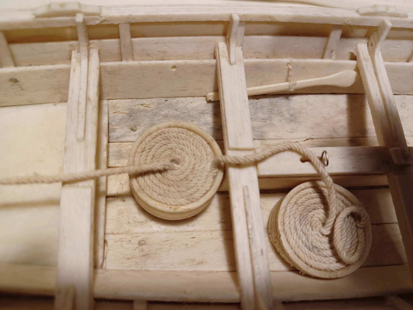
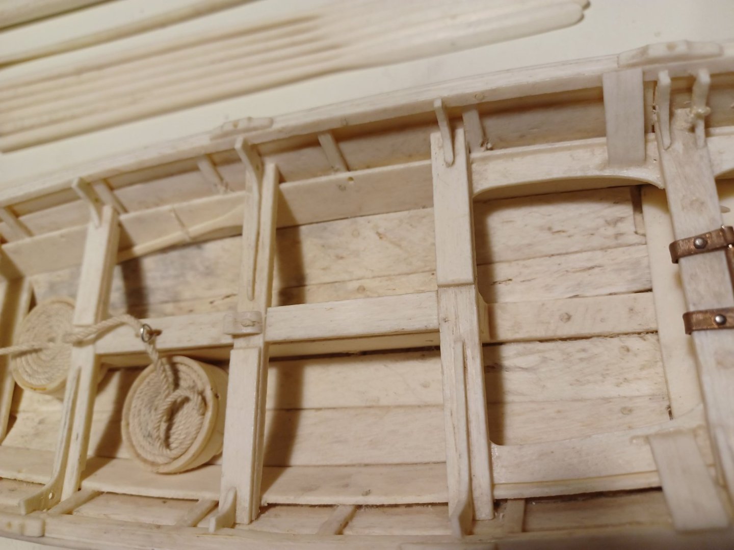
After being busy with other projects, I now want to continue with the restoration of the bone model I already showed you back in 2021. I found a couple of similar models in auctions around the world, several of them made by the same builder Albertino Sousa Luz. In fact, almost all of the models seem to be signed by A.S.Luz. So it is propably a retired (and very talented) whaler who made them rather then a local tradition. I dismantled my model, becaus it was a dirty mess and started to clean it first with a dry brush and then with a wet ear stick. I am happy to say, that no parts are missing. All of the long oars, the steering oar, the paddles, the rudder, the rowing oarlocks and the hunting tools are still there. Some of them were fixed to the model with rope. I removed these ropes, because they were very dirty and partly unraveled, I will replace them. Here you can see the harpune rope-drum. I also cleaned the sails. The mast-rings are made from plastic and don't look very nice. I will propably replace them by rings made from bone. Matthias

- 7 replies
-
- 9
-
-
- whaleboat
- restoration
- (and 2 more)
-
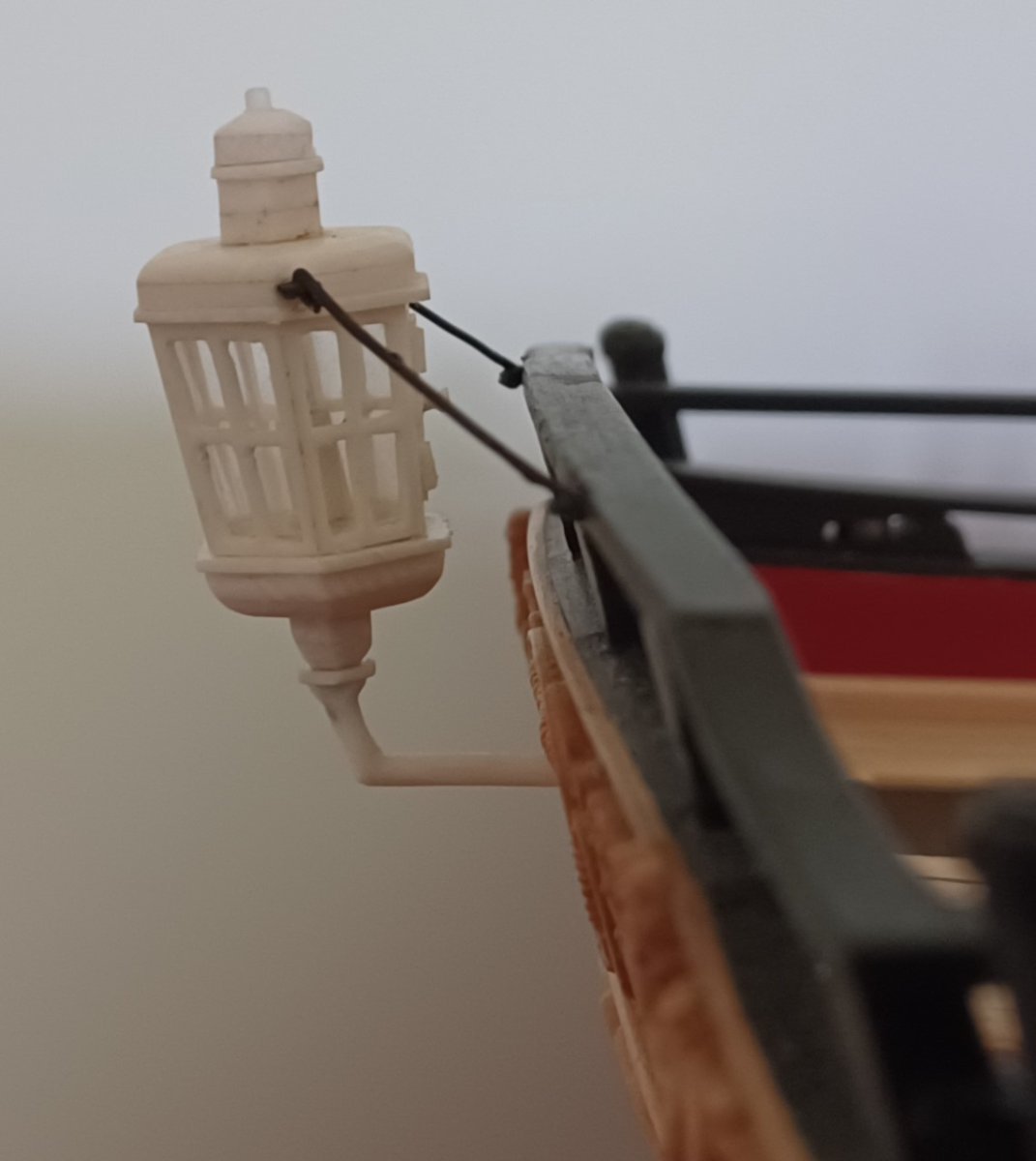
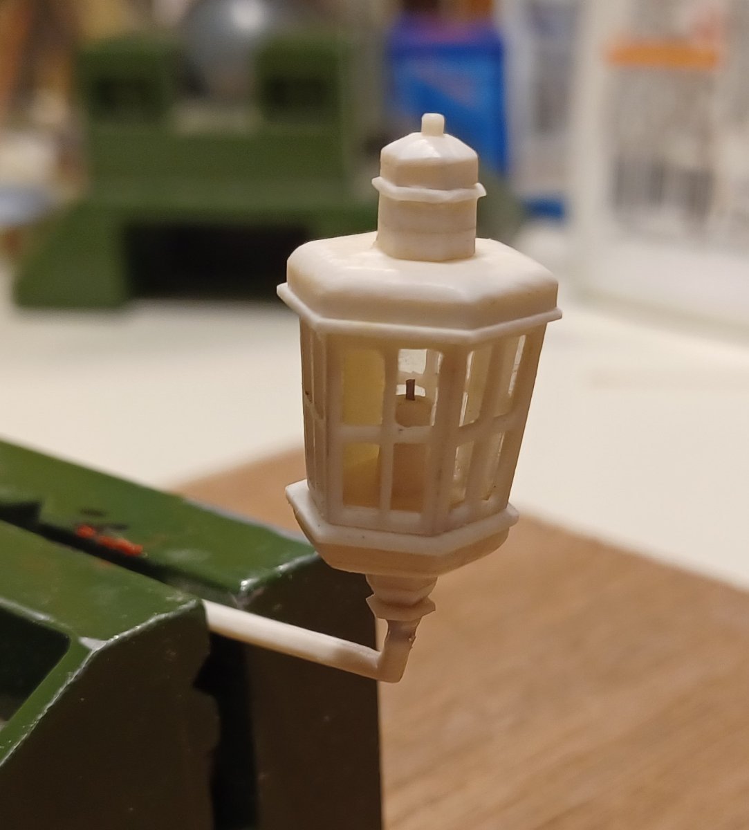
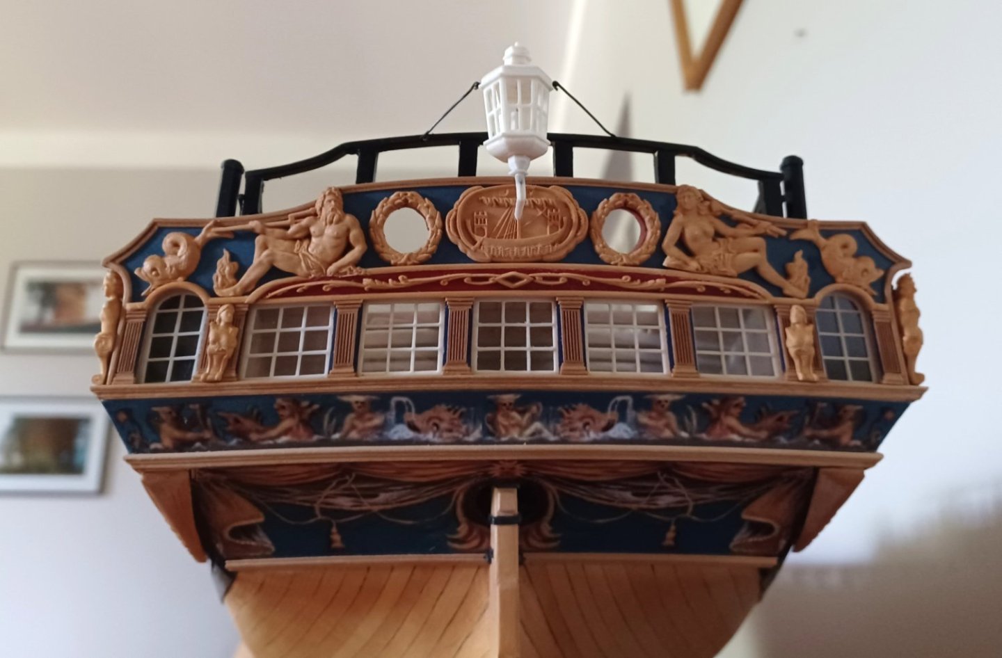
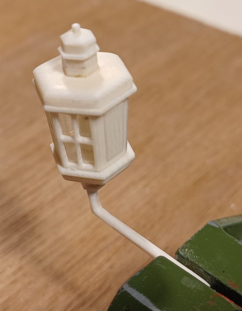
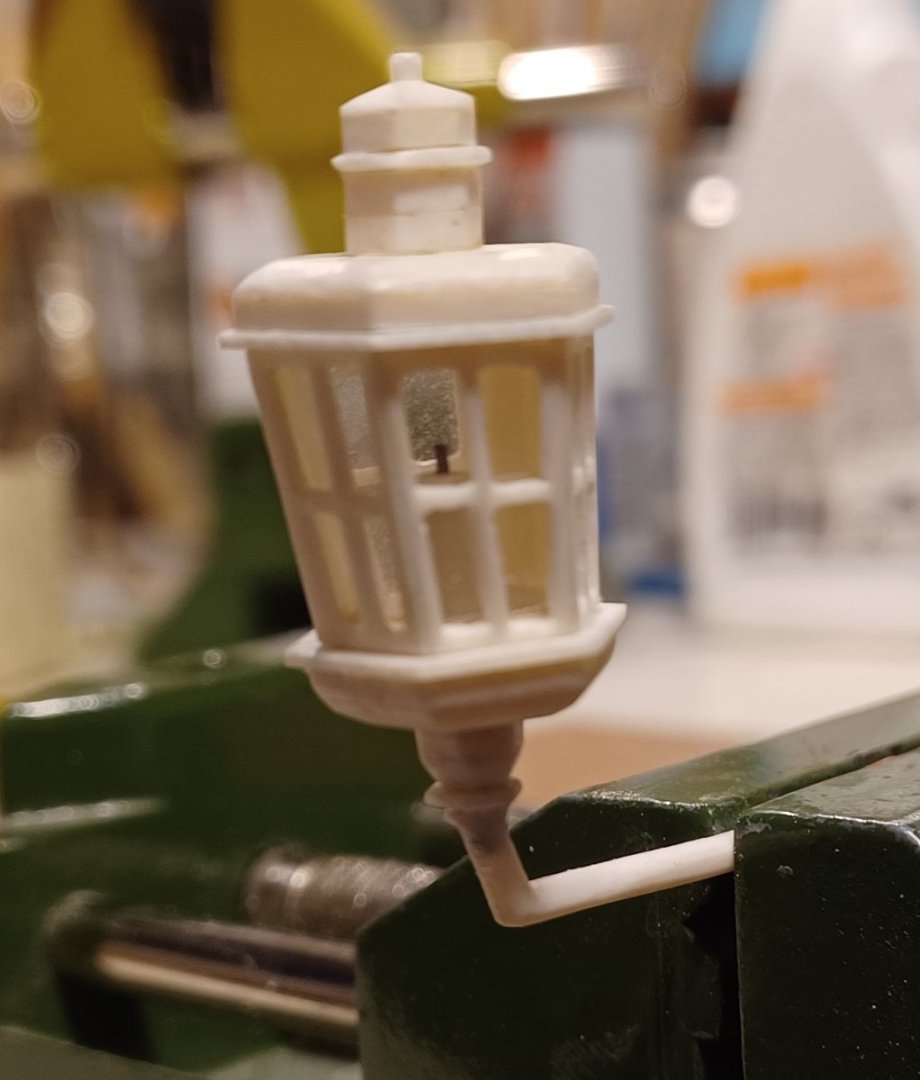
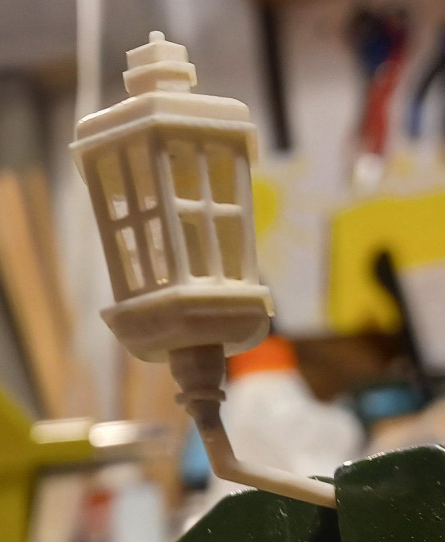
Hi Everybody, still no progress with my display case, but I mounted the stern lantern on the model. Matthias


-
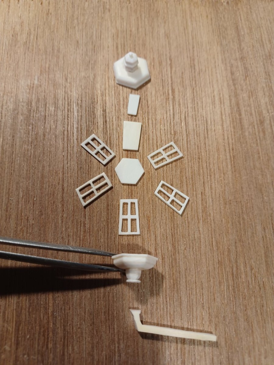
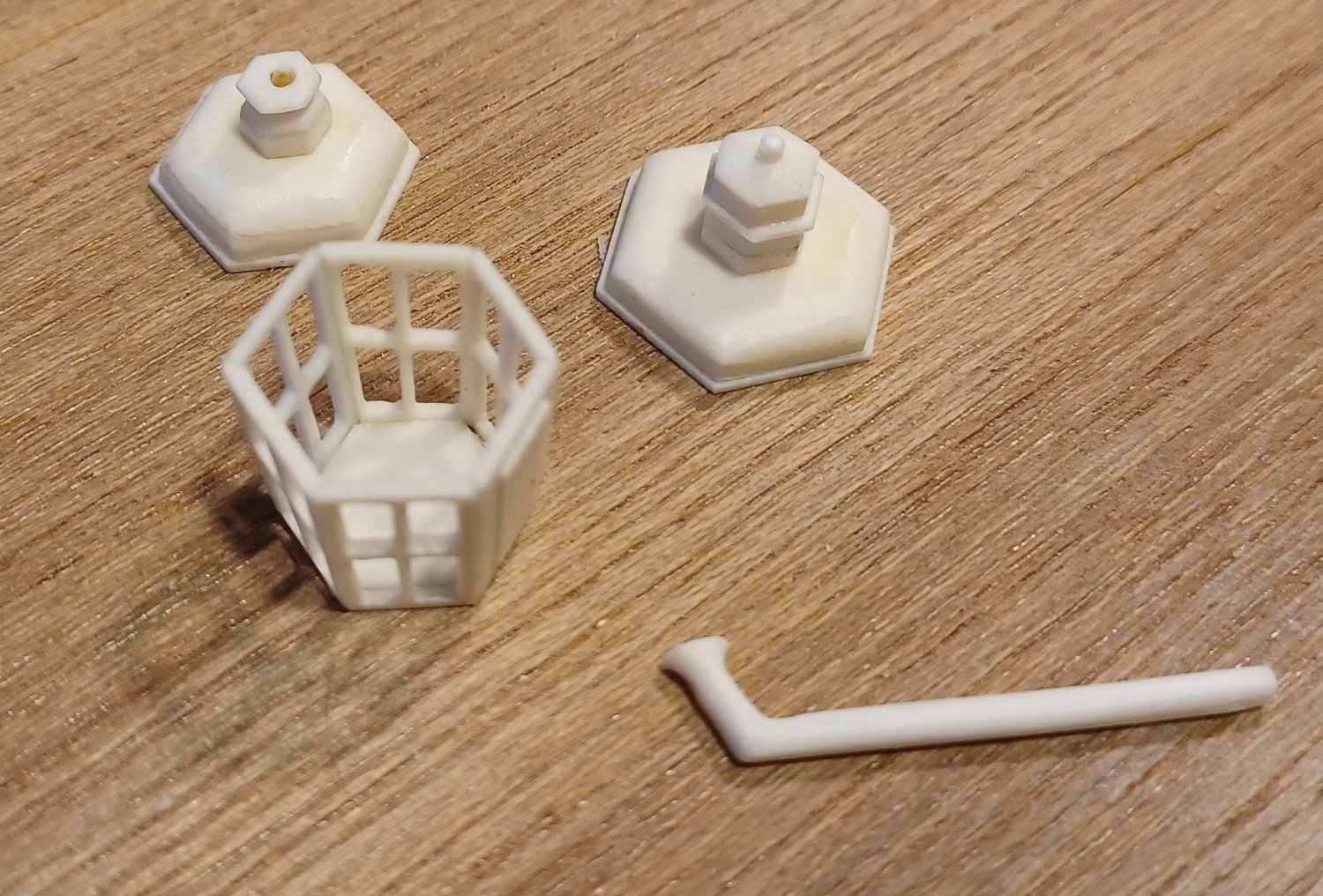
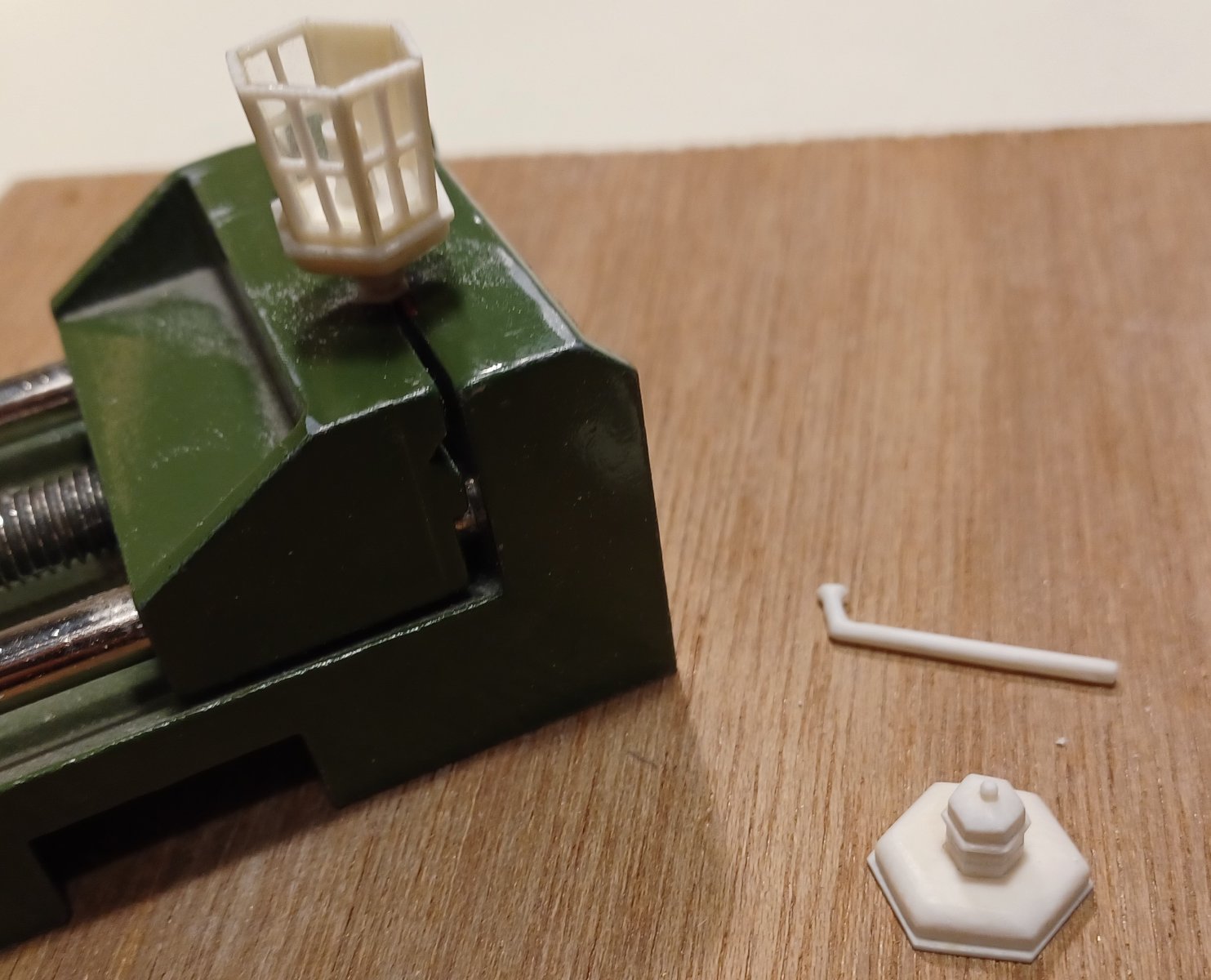
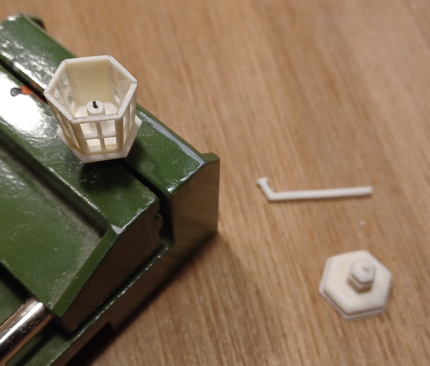
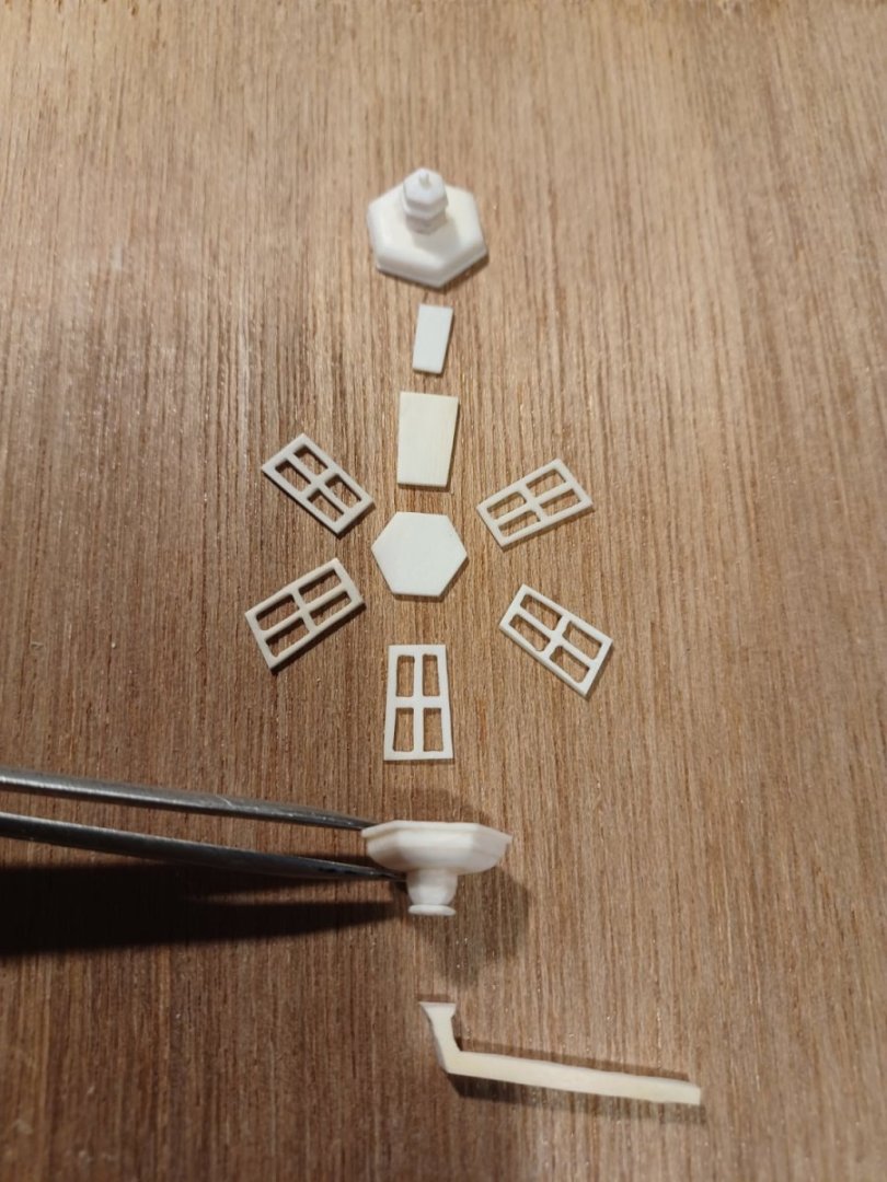
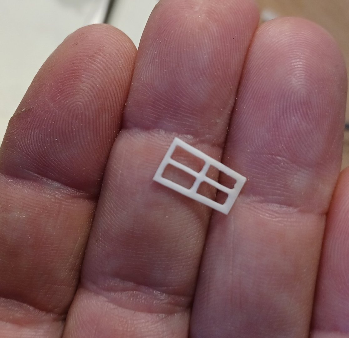
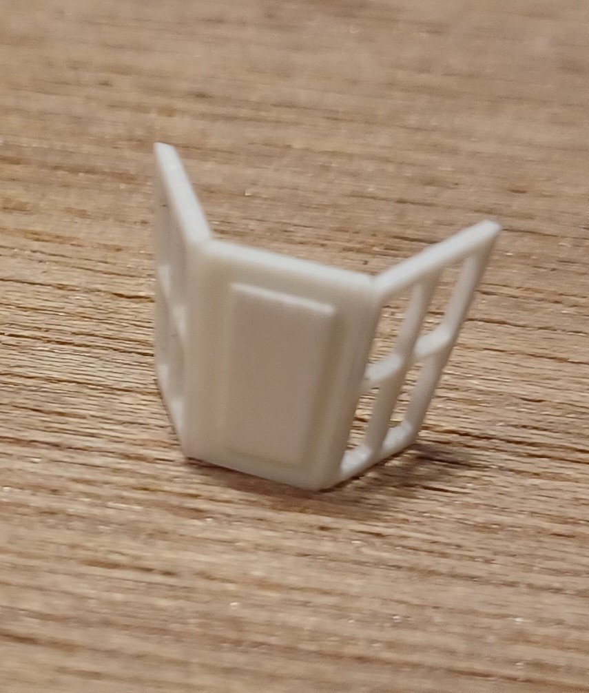
Thank you! This weekend I made the stern lantern, as I said from ivory agein, like some of the other features. I did not use laser cut, like I did for the galery-windows, but cut the parts with a jigsaw. I must say, this is better than laser cut, because the heat of the laser somehow affects the material and makes it a bit yellow and more fragile. After cutting out all the parts I made the bottom and the roof, wich are assemblied from several parts. The windows needed a careful sanding, to not look too crooked. Then I glued the parts together... ...added the candle and the glazing... and here we go, everything finished for being mounted on the model. I will add the lantern to the model, once the display case is completed. Otherwise I will break it of for shure, while carrying the model around. Matthias


-
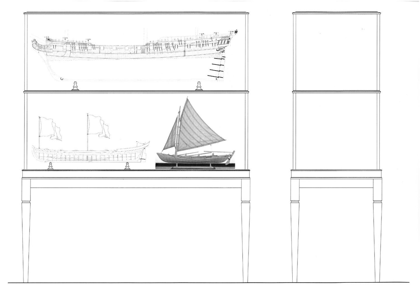
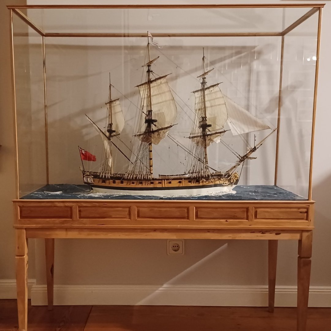
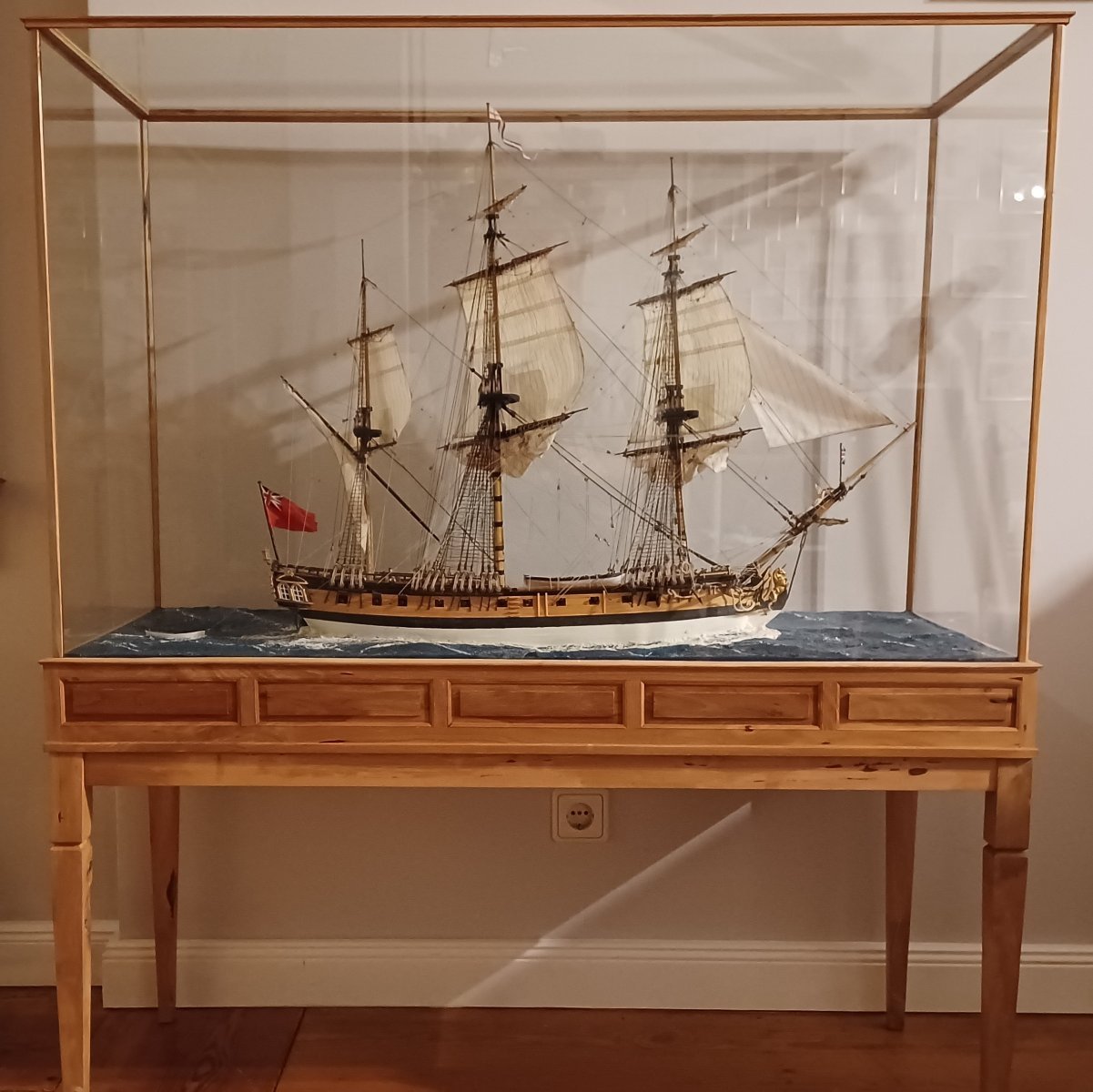
Hi Don, I will make a display-case similar to the one I made for my HMS-Unicorn model. I have got same pear-wood for this wich I plan to use. Here you can see the case I made and the drawing for the new one. I will post pictures, when I build it. Matthias