Heronguy
-
Posts
863 -
Joined
-
Last visited
3 Followers


.thumb.jpeg.fc5d633a7b34428fcf19419a73d56d55.jpeg)
About Heronguy

Recent Profile Visitors
3,430 profile views


.thumb.jpg.6d6ee4bdbfaac2c58ecc77e7b80ae374.jpg)


-
 FrankWouts reacted to a post in a topic:
HMS Winchelsea 1764 by Heronguy - 1/48
FrankWouts reacted to a post in a topic:
HMS Winchelsea 1764 by Heronguy - 1/48
-
FrankWouts reacted to a post in a topic:
HMS Winchelsea 1764 by Heronguy - 1/48
-
Edwardkenway reacted to a post in a topic:
Introducing myself and already seeking advice
-
Keith Black reacted to a post in a topic:
Introducing myself and already seeking advice
-
FrankWouts reacted to a post in a topic:
HMS Winchelsea - FINISHED - 1764 - by Chuck (1/4" scale)
-
GrandpaPhil reacted to a post in a topic:
Barque Stefano by Heronguy - MarisStella - 1:63
-
FrankWouts reacted to a post in a topic:
HMS Winchelsea by Beckmann 1/48
-
Dale Hallier reacted to a post in a topic:
Bluenose II by Heronguy - Artesania Latina #20500 - Scale 1:75 - 2nd build
-
FrankWouts reacted to a post in a topic:
HMS Winchelsea 1764 by Heronguy - 1/48
-
FrankWouts reacted to a post in a topic:
HMS Winchelsea 1764 by Heronguy - 1/48
-
Heronguy reacted to a post in a topic:
Le Coureur 1776 by captain_hook - CAF - Scale 1:48
-
Heronguy reacted to a post in a topic:
Le Coureur 1776 by captain_hook - CAF - Scale 1:48
-
Heronguy reacted to a post in a topic:
Barque Stefano by robdurant - MarisStella - 1:63
-
 I'm still working on my PdN but tell me what you need - written instructions or plans?
 -
Heronguy reacted to a post in a topic:
Barque Stefano by robdurant - MarisStella - 1:63
-
Heronguy reacted to a post in a topic:
Barque Stefano by robdurant - MarisStella - 1:63
-
Heronguy reacted to a post in a topic:
Barque Stefano by Heronguy - MarisStella - 1:63
-
Heronguy reacted to a post in a topic:
Barque Stefano by robdurant - MarisStella - 1:63
-
Hi Rob, I didn't use side cutters. I used a scalpel or x-acto blade to free up the 1st row from the panel. Subsequent rows just need the end tags cut then bend the whole row back and forth a couple of time and its free. I did bend a few individual plates. They straighten out just fine as long and the bend is not too sharp. When it came to trimming plates (near the end of the coppering process) I cut them with snips that I bought for the purpose. I'd get a slight curl but it was easy to flatten. Biggest challenge I had (other than tedium) was getting the plates to adhere to the hull. Ended up using thin CA glue. Weather is getting better here so may get back to the shipyard soon.

- 79 replies
-
- 1
-
-
- marisstella
- barque
- (and 1 more)
-
Heronguy reacted to a post in a topic:
Help needed for handling cross-grain parts without splitting
-
Heronguy reacted to a post in a topic:
Avos by etsinko - FINISHED - Master Korabel - 1:72 - Russian tender
-
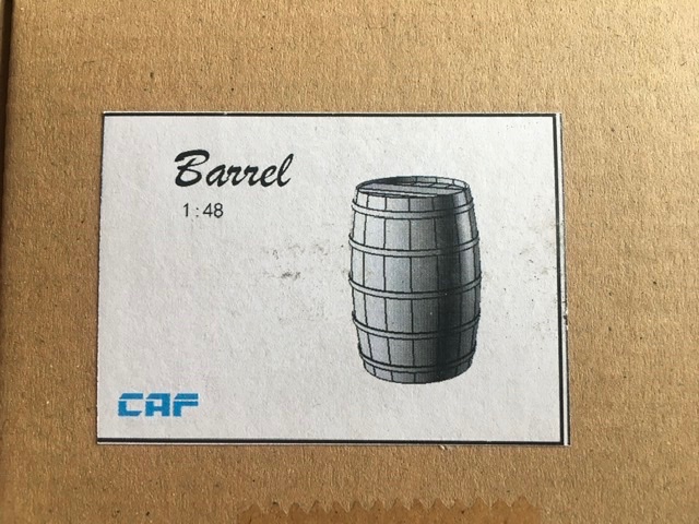
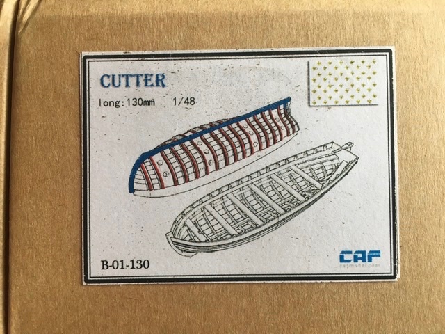
Hi Lou. The ship’s boat (cutter part no L130) was the only extra (other than a rotary cutter that I’m concerned will never float!). No little people. I had ordered a set barrels and a cutter (different version that used a moulded hull to form the ribs on). It will be interesting to me to find out which cutter (excluding the rotary 🤪) turns out to be easiest to assemble. I’ve had ship’s boats from Model Expo, Dusek and Master Korabel so far. Two of them were fun to build.


-
great project and you’ve got a good start! It will be fun to watch. I’ve got the kit now and am keen to see you approach to construction steps. Given how delicate the frames are at this stage it seems like it will be a challenge to clamp them while you fair the tops of the frames. Have you done any bevelling on the frames near the bow or stern yet?
-
Heronguy reacted to a post in a topic:
Le Coureur 1776 by UdoK - CAF - 1/48 - POF
-
Very handsome indeed! Well done.
-
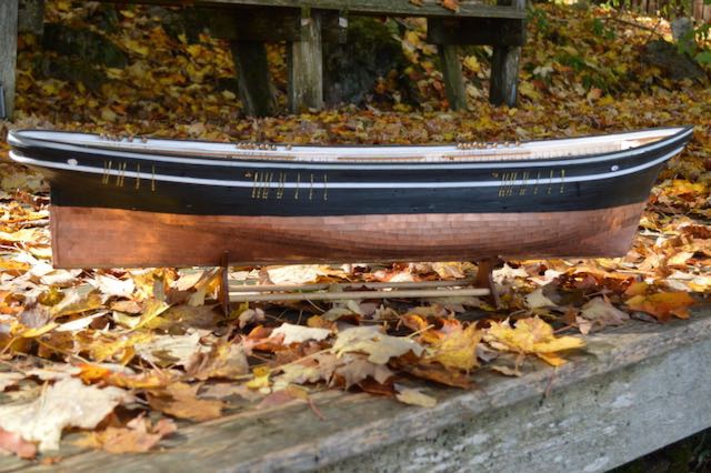
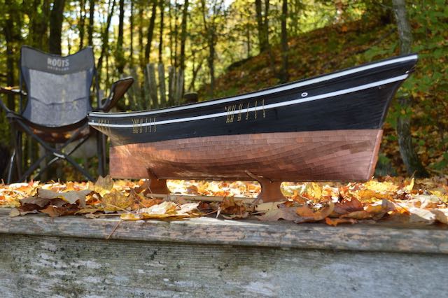
At long last I've finished the coppering of the hull. It hasn't been a very intense effort until the last month but I'm happy to have completed it and am satisfied with the results!
- 79 replies
-
- 13
-
-
- marisstella
- barque
- (and 1 more)
-
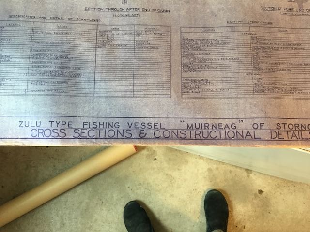
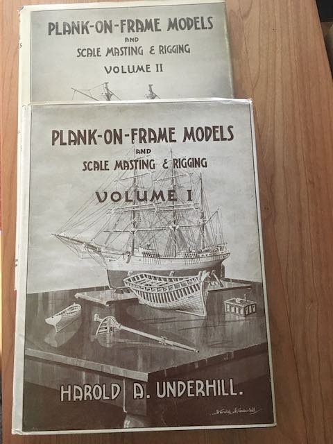
I was just gifted with a set of blueprints for the Zulu Muirneag. Plans were drawn by Harold Underhill in the 1950's. His book "Plan-on-Frame Models" has reduced version of three of the plans. I can't use the blueprint set so they're listed in Traders... One source of detail.
- 195 replies
-
- 1
-
-
- lady eleanor
- vanguard models
- (and 1 more)
-
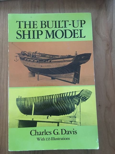
An unblemished, and perhaps unopened copy of this classic. I have it already so I'm offering this one to whomever wants it. I'll just ask for the postage cost.
-
These are Harold Underhill's 6 sheet blueprints of the Muirneag. Volume 1 of his Plank-on-Frame Models has versions of 3 of the 6 sheets. This is the full set. They are apparently available online in digital format for about $70. Asking $30 plus shipping cost.
-
A friend gave me her husband's copies of Plank-on-Frame Model volumes 1 & 2. Since they are already on my shelf I'd be happy to sell them. Both in very fine condition. They seem to be boy $40 on abe books. I'll sell for $20 plus postage.
-
Encouraging - thank you!
-
Thanks for the advice. I had cut the frame guides from some 3/64" sheet but couldn't get them to stay in place even with rubber band pressure. Clearly then 'll have to unglue the ST-CD upright and adjust the slots until things more closely match the framing guide.
-
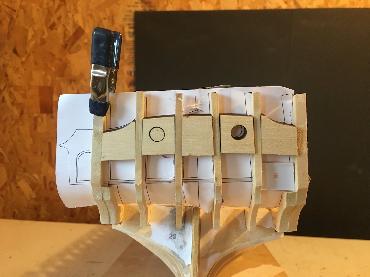
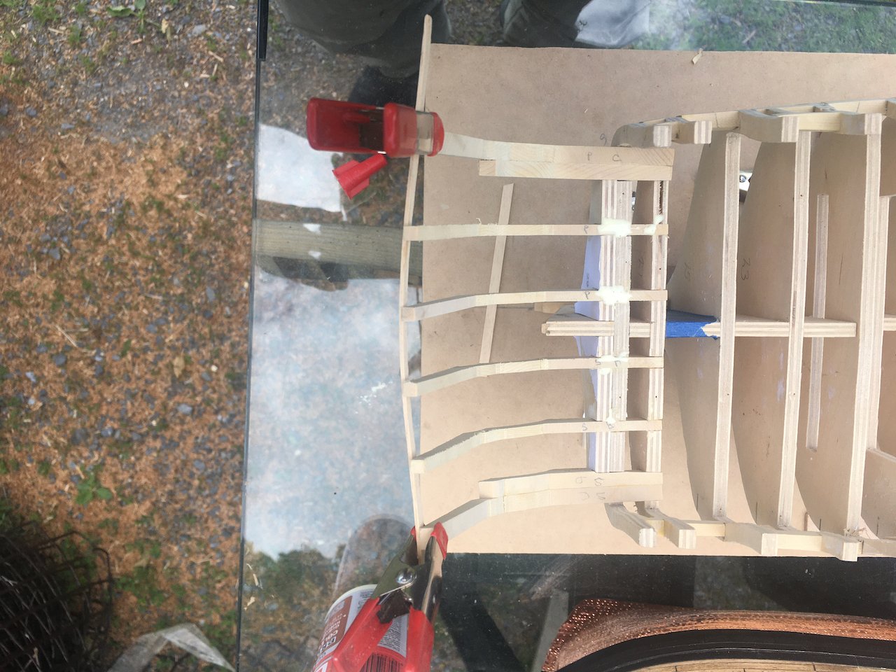
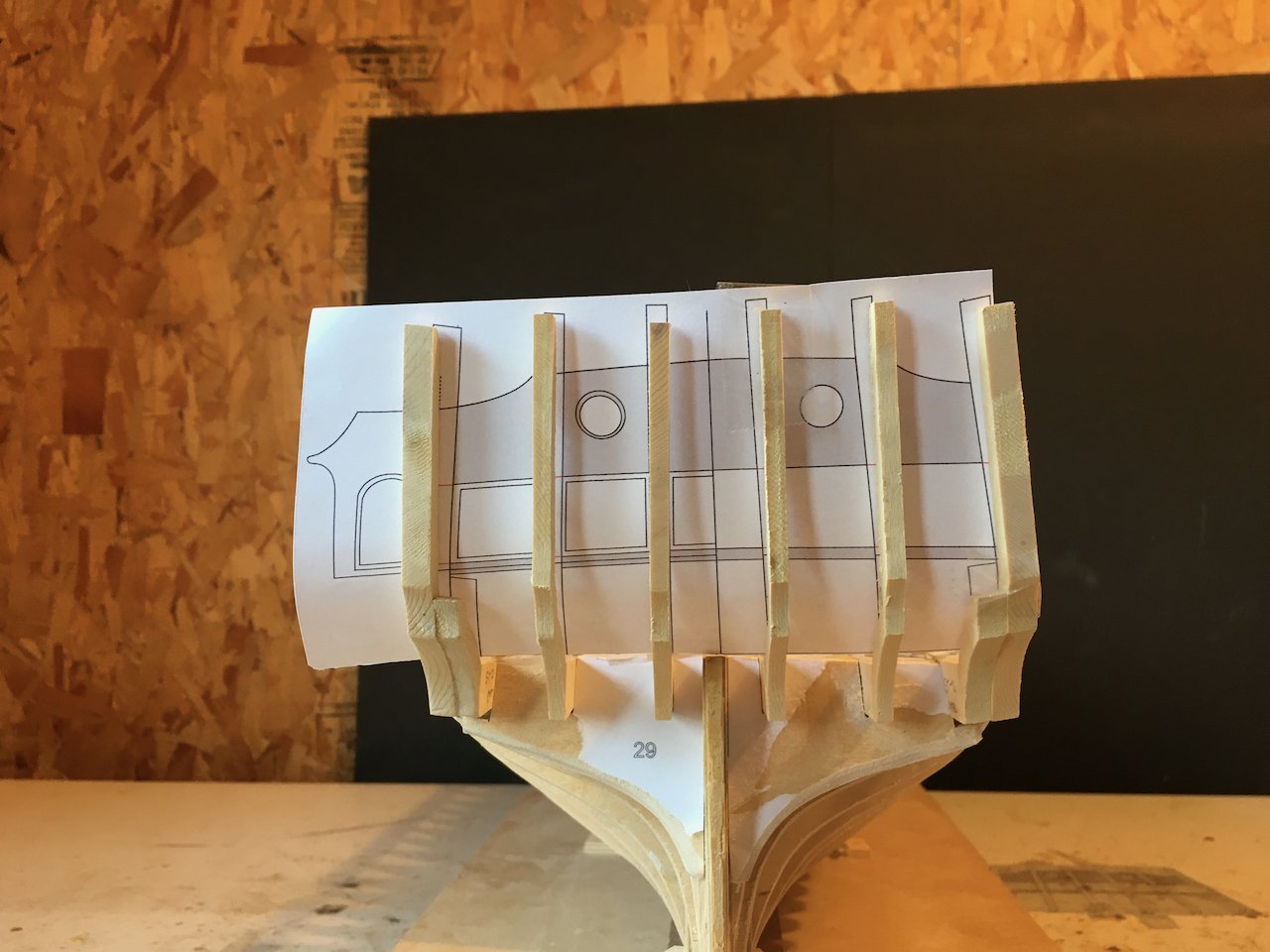
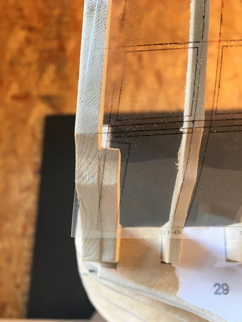
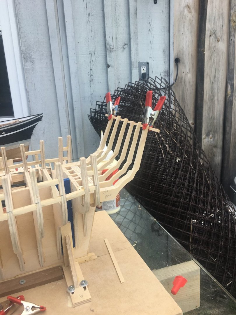
Now I have run into some difficulty and would benefit from advice! I'll preface my problem with a reminder that I had decided to try to scratch build. To me that meant milling my own wood and using Chuck's plans to cut out all the pieces rather that using the lasercut components. I did purchase the chapter 1 laser cut material as a reference. So far I have used it only to compare my scratch bits with the precision ones. (aside : as I look at quarter gallery description in Chuck's build log and the more advanced builds in this group I'm questioning my hubris at attempting this - oh well) To the stern. I slapped it together with the hope that things would lie just right. A quick visual inspection showed that ST-A on the port side was a little low but maybe that didn't matter (I've subsequently fixed that). I printed the stern frame guide to use as a visual check on the stern uprights - printed on clear acetate so I could put it on the outer surface. Things didn't look too good! Printed again on paper so I could glue it to be inside surface for an easier view. The middle three uprights I could coax into alignment with the draft quite easily but the outer one are very rigid and not able to be coaxed with pressure. (BTW this image is before I fixed ST-A(port)) I figured I was going to have to remove ST-CandD from both port and starboard, change the angles of the slots in bulkheads 28&29 and iterate until I got a better visual. However before starting that I thought to try the stern window guides to see how well they fit. They weren't bad so I I tried the upper sills. Here I had another disappointment. Using the laser cut sills to check it appears the the port side fit nicely but the outer two on the starboard side don't. As Chuck describes in the chapter 1 notes the guides will fall out if the sills need a bit of tweaking. When I see how far out the starboard ST-C&D upright is I'm a a loss for what I should do to try to salvage what's here. Advice gratefully accepted!
-
You're motoring' along I can see I'll have to catch up to you!!
- 152 replies
-
- 1
-
-
- model shipways
- syren
- (and 1 more)