Ben752
-
Posts
64 -
Joined
-
Last visited
Content Type
Profiles
Forums
Gallery
Events
Everything posted by Ben752
-
Kris, I shared a few things just to show some similar research but totally agree with your analysis. I was curious if you happen to have Mac version or even better a GitHub repo with the source? I’ve encountered the same challenge and love your approach. As an aside, I wrote a small a Python script that used scipy’s genetic algorithm to fit splines that output control points compatible with how Fusion 360 constructed knots. Great work!
-
Veritas Miniature Worktop from Lee Valley Tools
Ben752 replied to Jack12477's topic in Modeling tools and Workshop Equipment
I have quite a few of the miniatures, I use the shoulder plane and block plane constantly. My favorite vice is one of these https://www.cousinsuk.com/sku/details/vices-bench-vice-jaws/v9692
-
Just want to point out this is: Awesome Computer Vision research The known references certainly assist dramatically. I recall reading a paper about removing lense distortions by using a reference photo of a checkerboard, fitting the edges to make grid points and then fitting a transform function. Seems like an adaptable solution. https://mzucker.github.io/2016/08/15/page-dewarping.html https://arxiv.org/pdf/2007.09824.pdf https://github.com/gwxie/Dewarping-Document-Image-By-Displacement-Flow-Estimation/blob/main/90_paper.pdf
-
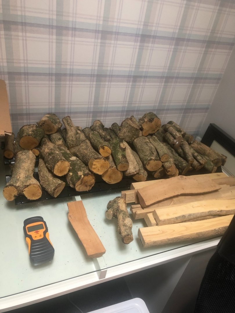
Thought others might like to know that there has been a small bit of green and some dry boxwood as of late, presumably due to the ongoing infestation of the box tree moth caterpillars. Regardless, I’ve ordered from several different sources listed below: https://www.workshopheaven.com/wood-blanks/boxwood.html (limited stock) https://www.ebay.co.uk/usr/hucrompto0 (in stock) https://www.englishwoods.co.uk (out of stock) The green logs, albeit many are twigs, I purchased as lot for £9 plus shipping. So deals are out there, I found eBay saved searches indispensable.
- 1 reply
-
- 7
-

-
H.M.S. Atalanta - Drafting my own plans
Ben752 replied to Ben752's topic in CAD and 3D Modelling/Drafting Plans with Software
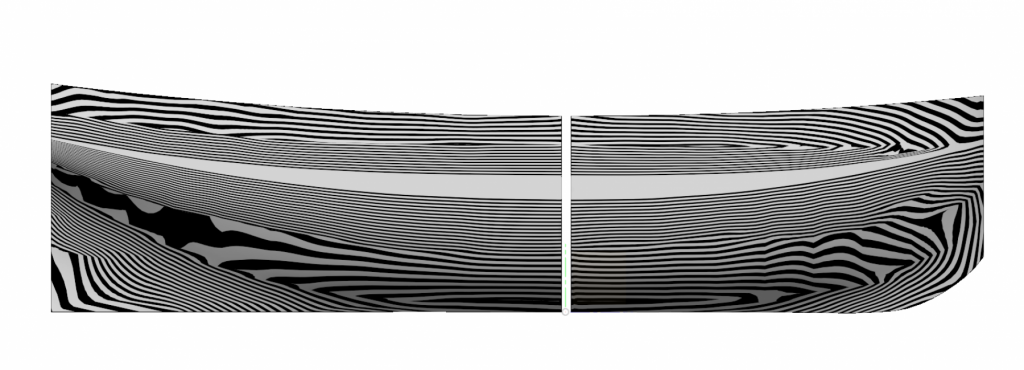
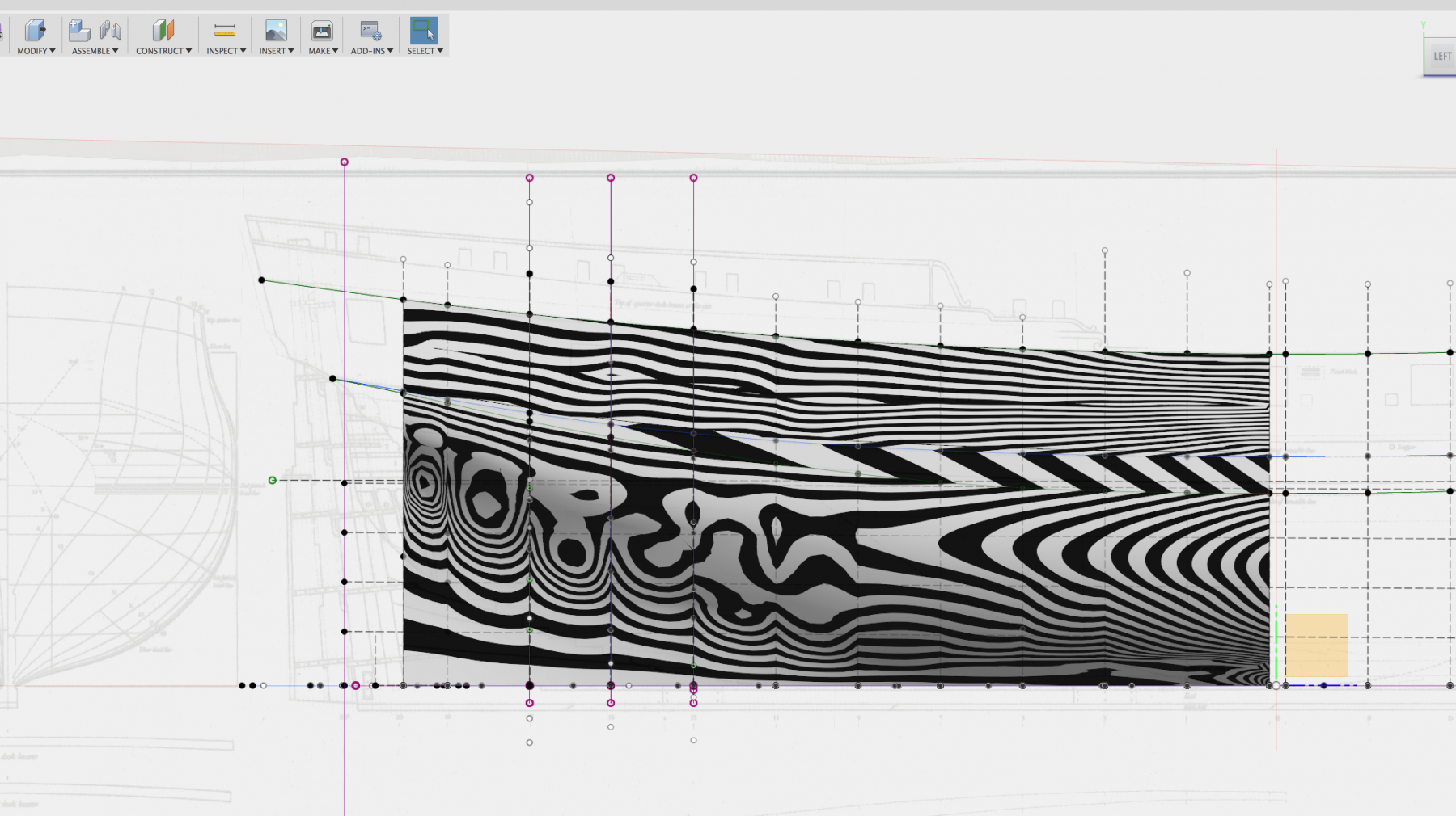
"a pile of patches" was actually pretty accurate in that it was constructed with several tangent arcs. I had a similar experience of feeling it was just not right -- and that a different technique was needed. Fusion 360 has curvature combs, draft analysis and curvature map analysis features. Here is a curvature map analysis I ran, I haven't been able to to see much except when using the min/max settings and cranking the max values way up. Hopefully this is a good thing (my prior hull showed more variance). The CVs close together are a byproduct of using a mathematical fitting technique. Fusion using fixed spacing for knot placement of curves. While I'm not NURBS expert from the match side, my understanding is that if you are using uniform knots then you would need two CVs close together for it to generate the curves. Now whether they should be split vertically like that, my guess is probably not. I did run the fitting routine several times and it tended to favor placing them like that. While i'm not totally satisfied with it, i'm trying to remind myself that I aught to start working on other areas and come back to it later. When I intersected a plane with the hull the pattern for a frame seemed to match up well against other resources I have so hopefully that's a positive side.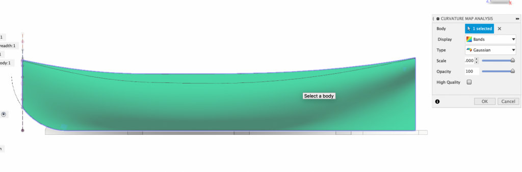
-
H.M.S. Atalanta - Drafting my own plans
Ben752 replied to Ben752's topic in CAD and 3D Modelling/Drafting Plans with Software
That was my thinking! My own inability to be happy with moving the CVs (i'd never be happy enough) led to me searching for a different solution. I ended up using the Python library scipy as it has the relevant spline objects in scipy.interpolate and I used the differential evolution algorithm as the solver. -
H.M.S. Atalanta - Drafting my own plans
Ben752 replied to Ben752's topic in CAD and 3D Modelling/Drafting Plans with Software
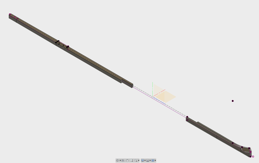
That is correct. It took quite a few tries to figure out exactly how AutoDesk implemented the spline knots (they actually confirmed it in a support request in their forums). In the first screenshot above, I used measurements at each station line and it gave me the output of the 7 control vertices (with the first and last being the corresponding points I provided). -
H.M.S. Atalanta - Drafting my own plans
Ben752 replied to Ben752's topic in CAD and 3D Modelling/Drafting Plans with Software
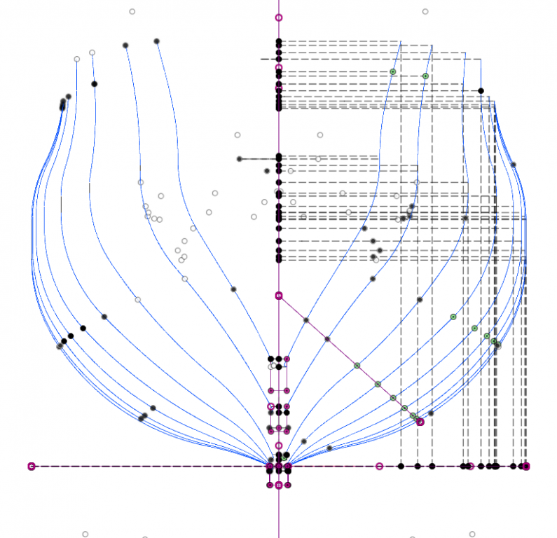
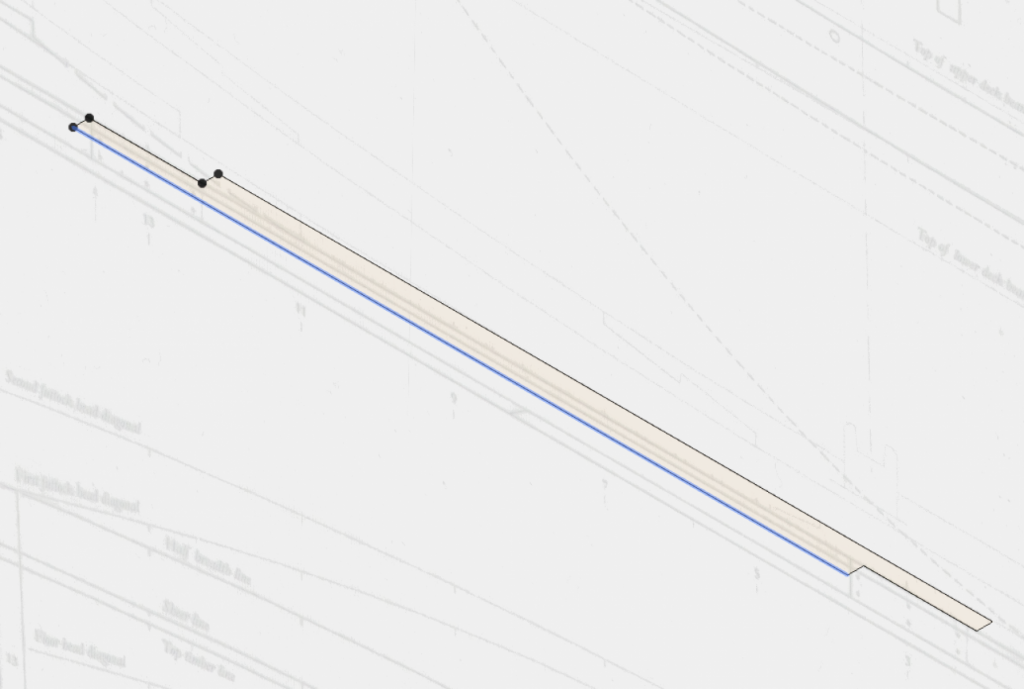
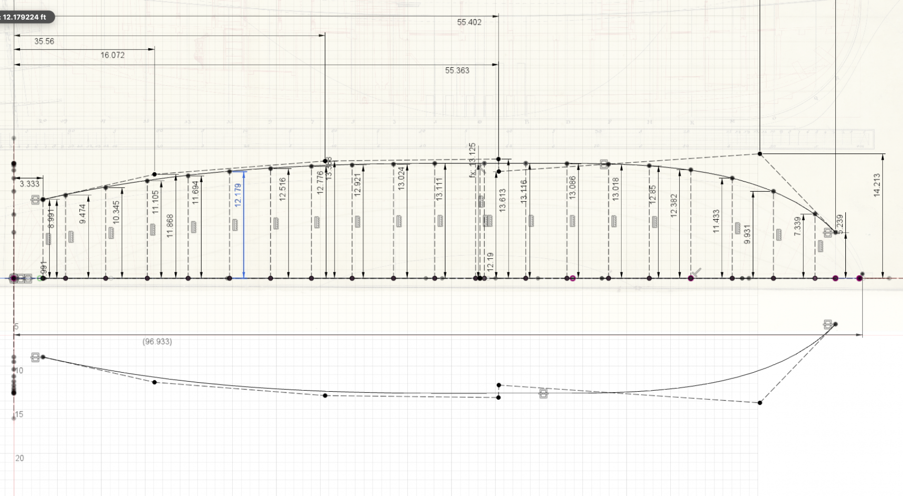
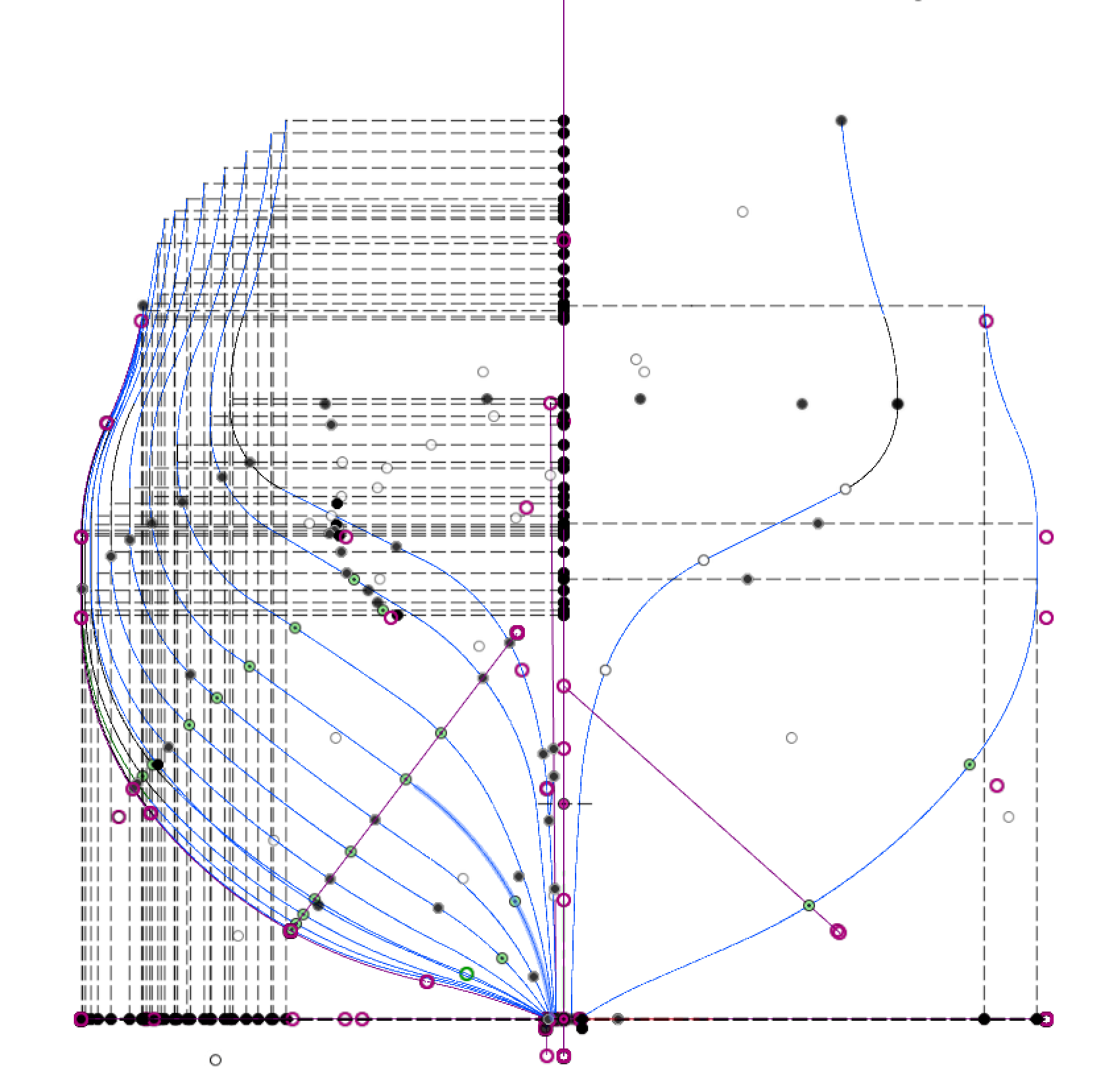
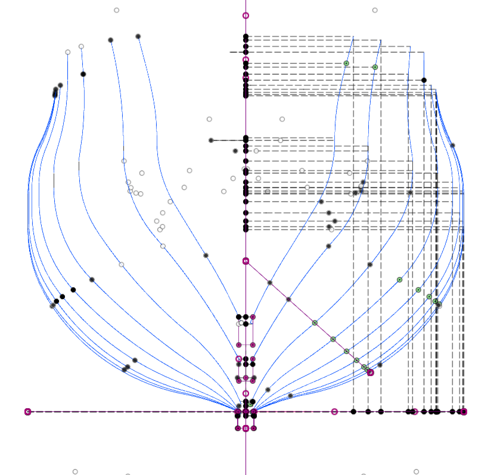
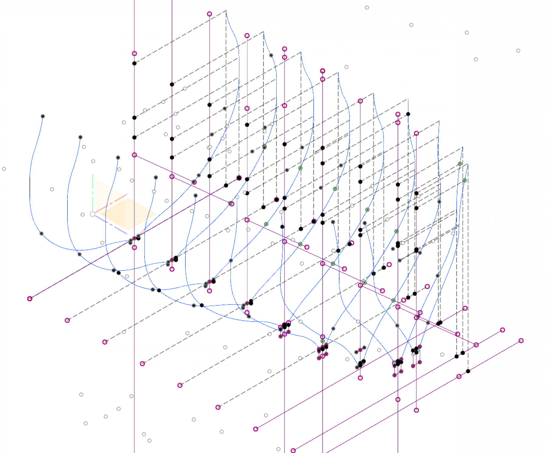
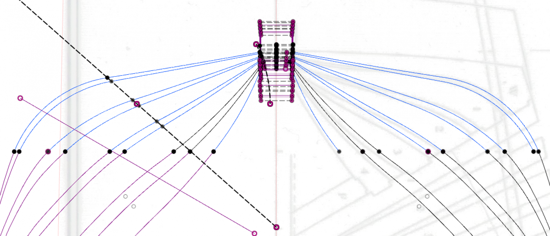
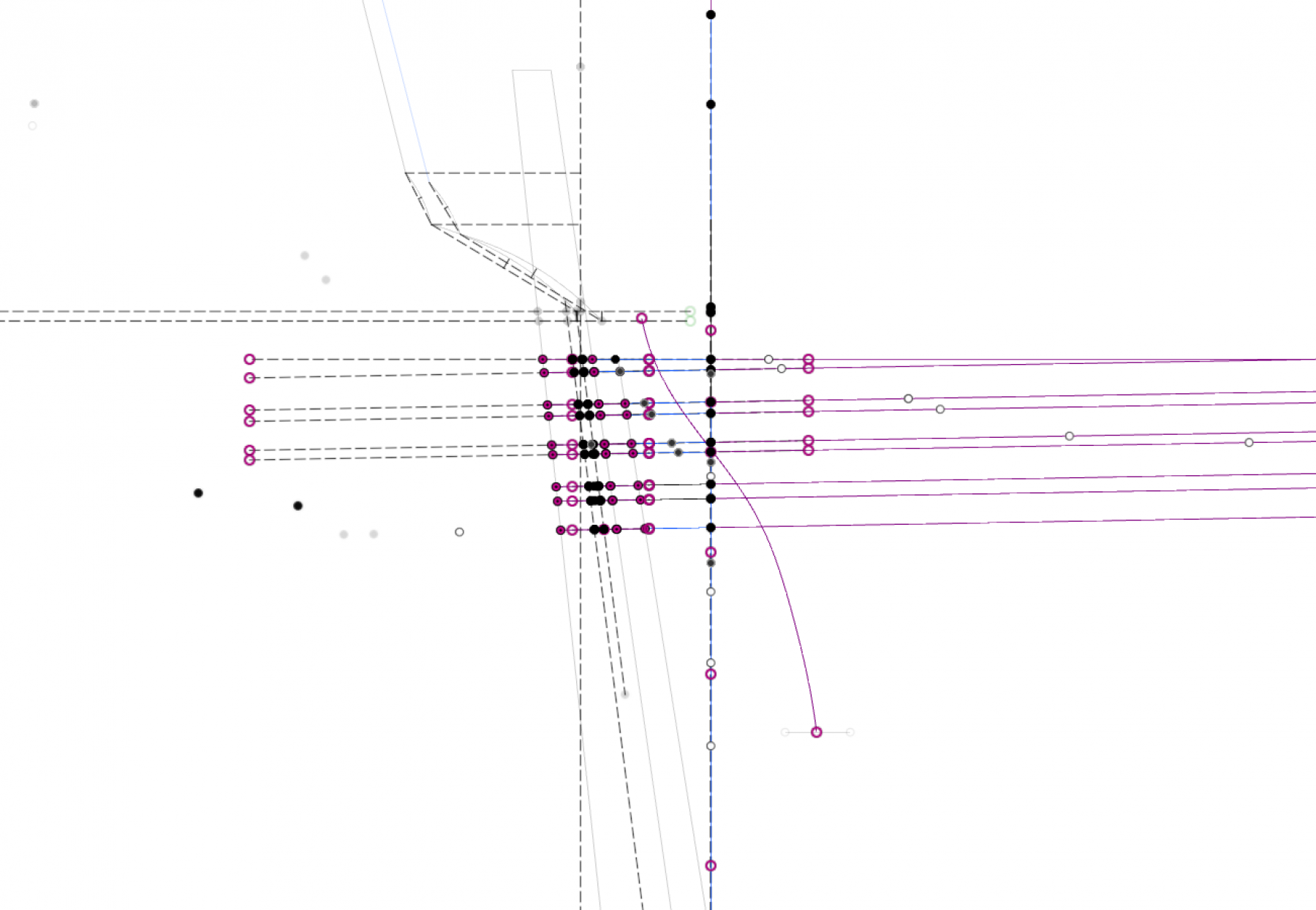
Hi everyone, I wanted to give an update on my progress. Normal life stuff has been busy since the last post. My company was acquired, subsequent expansion of our office here in the U.K., met a nice English girl and more focus on my U.S. Brig Niagara. All sorts of great things. Anyways, enough about that. As I was progressing through later parts of drafting, I came to realize I wasn't really happy with how some of the lines were formed. Also, AutoDesk launched CV splines for Fusion 360! I ended up starting a starting over my 3d model to incorporate lessons learned about Fusion and feedback from ya'll. Also, I stopped straddling the fence on how much to use from the TFFM plans and the original drafts -- I've decided to go using the original references almost exclusively. In this second start, I've switched to the following techniques in fusion: Using CV splines for the body plan and striving to keep the same number of control vertices Defining key curves using CV splines that are fit using numerical optimization methods. This last part took some R&D (I work in technology and spend a bit of time doing data science/AI type solutions). Below is an example of what I've done relating to this. I started by taking measurements off the drafts and correlating them across plans. This yields points to fit, one challenging is that fitting CV Splines isn't a common practice. This is partly because they are parametric which to my knowledge doesn't have an analytical solution. What I did was use a genetic algorithm to solve for solutions that are very close using the points that match above. The result seems to be a more smoother fit that is much closer to real curve than I could manage moving points around. FWIW, there are a few naval architecture research papers that describe this technique. Below is an example of a breadth curve fit to the measurements. One interesting consequence of this is that it yields a fully constrained sketch in Fusion. It seems that splines also tend to work better when lofting. I think overall it's a much nicer fit than the previous technique I used.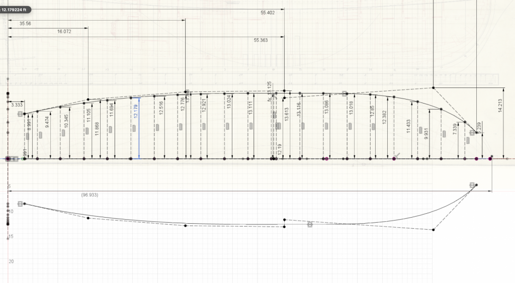
-
Opinions on Sherline DRO for Lathe
Ben752 replied to rtropp's topic in Modeling tools and Workshop Equipment
Does anyone happen to know the specs on the DC power supply for the DRO box? -
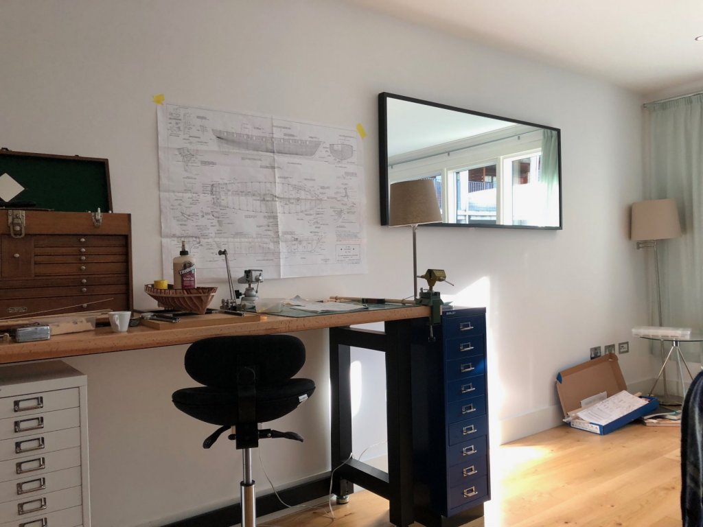
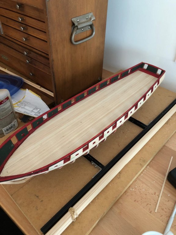
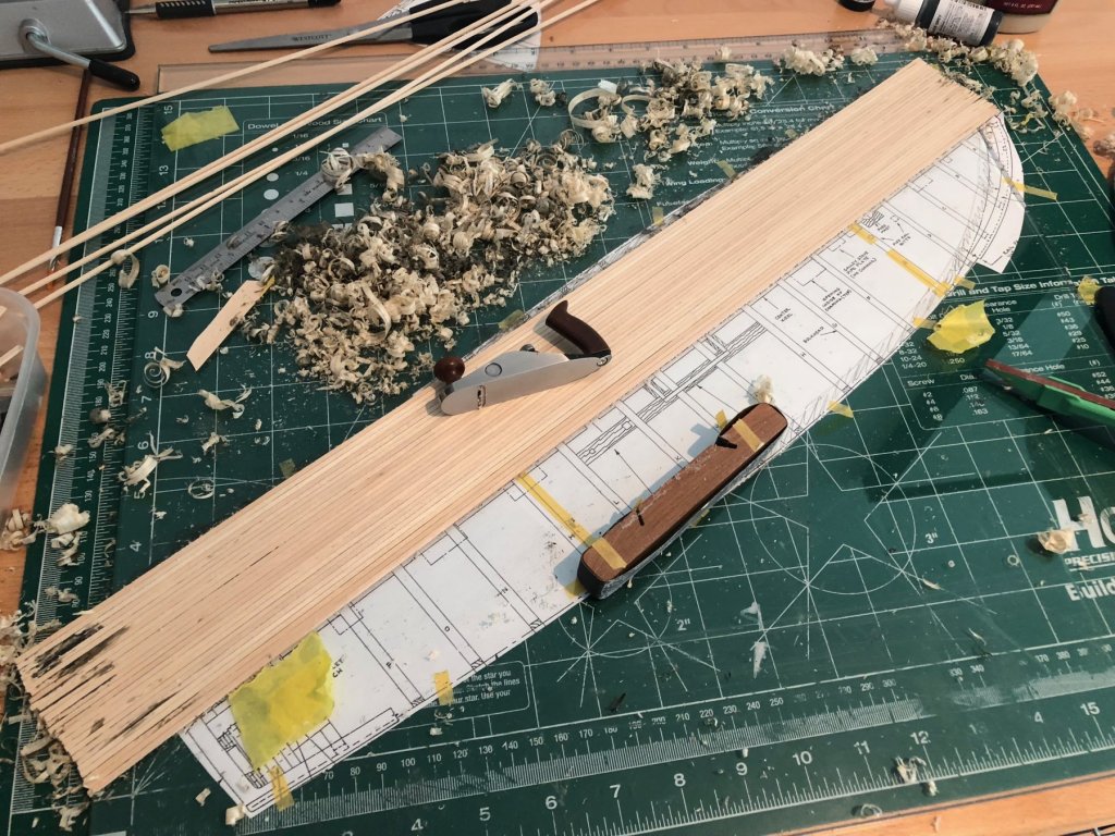
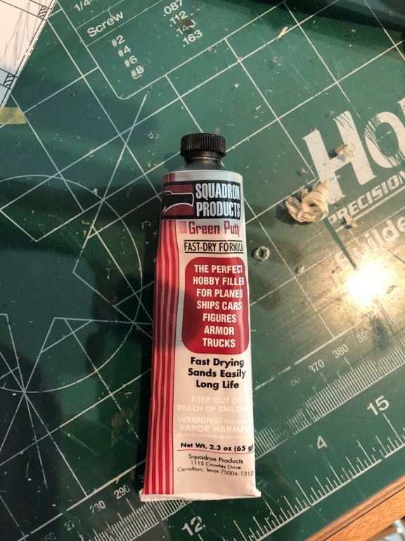
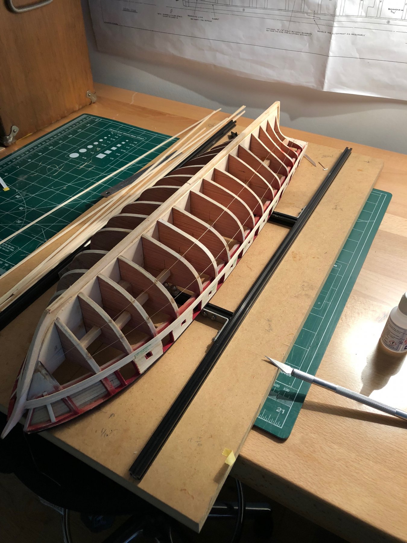
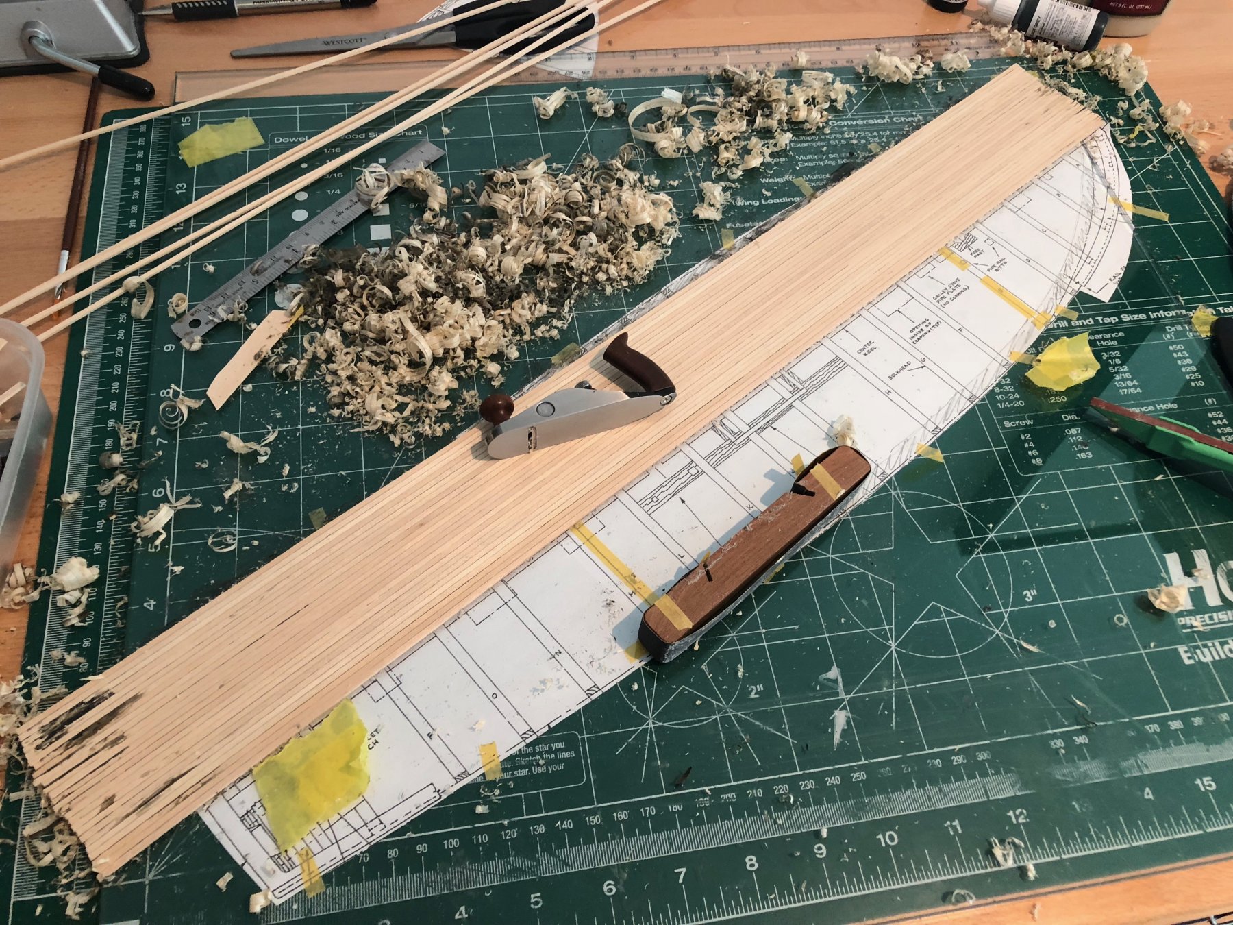
Finally the new model workshop setup after my move to Edinburgh, Scotland. There is a rather impressive hobby store called Wonderland Models just walking distance from my flat. I found this squadron green putty a good substitute for the bondo spot putty. I laid out the deck in a similar manner to xken, and used dark Titebond II along with some black grey to mimc the caulking. I then used my miniature veritas bench plane to remove the excess and borrowed a piece of glass from my furnished flat to create a flat surface to plane on. Later I ghosted the plank ends using a mechanism pencil, a compass to create a pattern to trim the deck. Last evening, I started laying out the plank belts using thread.

- 18 replies
-
- 5
-
-
- niagara
- model shipways
- (and 1 more)
-
Steel files vs. diamond files
Ben752 replied to Moab's topic in Modeling tools and Workshop Equipment
Steel files are the way to go, diamond impregnated ones seem to cut too fine for wood. After buying cheap ones and then later purchasing some Vallorbe needle files (I think Grobet USA is the same company), I can say it’s one of the best purchases I’ve made. https://contenti.com/jewelers-metal-files http://www.ottofrei.com/jewelry-tools-equipment/bench-tools/files If you want to hog lots of wood, woodcraft has some great needle rasps. -
H.M.S. Atalanta - Drafting my own plans
Ben752 replied to Ben752's topic in CAD and 3D Modelling/Drafting Plans with Software
Turns out they just launched CV splines (control vertices), https://www.autodesk.com/products/fusion-360/blog/july-26-2018-product-update-whats-new/ -
H.M.S. Atalanta - Drafting my own plans
Ben752 replied to Ben752's topic in CAD and 3D Modelling/Drafting Plans with Software
One of the limitations of fusion is that the spline support is far from great compared to others out there. They should be launching proper CV curves within the next year or so. They have recently published a post showing some of the upcoming capability, which should put them more inline with that of solidworks. -
H.M.S. Atalanta - Drafting my own plans
Ben752 replied to Ben752's topic in CAD and 3D Modelling/Drafting Plans with Software
This is great info. I've was going back and forth of using two different radii on this. Seeing this confirms it's possible that might be the case. -
H.M.S. Atalanta - Drafting my own plans
Ben752 replied to Ben752's topic in CAD and 3D Modelling/Drafting Plans with Software
Thank you druxey. I revisited the the sternpost and found that the roughly matching the rate of concave curvature inward on the the half breadth plan suggests the head would be approximately where you said it should be. Reconciling the different plans and sources certainly adds a wrinkle to selecting the right path when they don't appear to agree! -
H.M.S. Atalanta - Drafting my own plans
Ben752 replied to Ben752's topic in CAD and 3D Modelling/Drafting Plans with Software
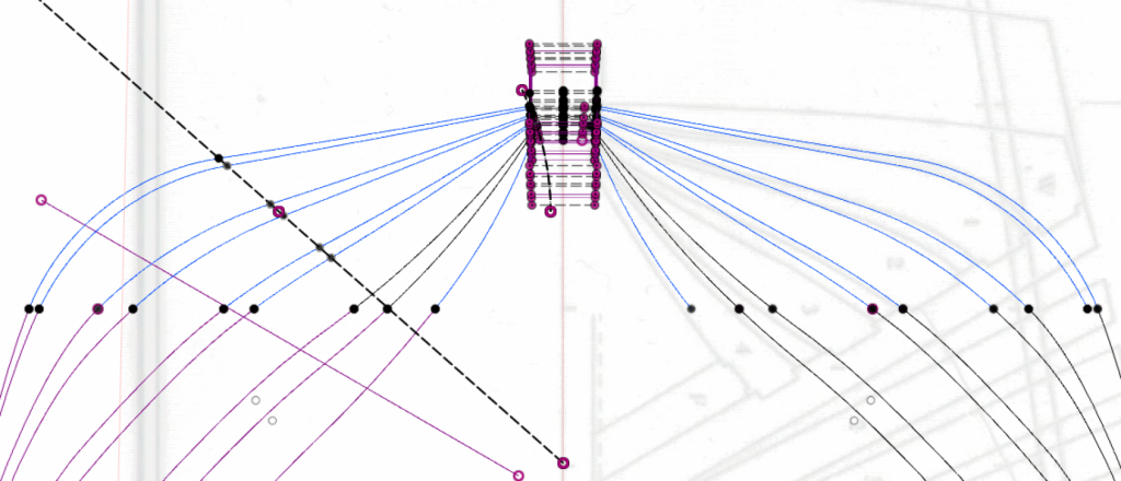
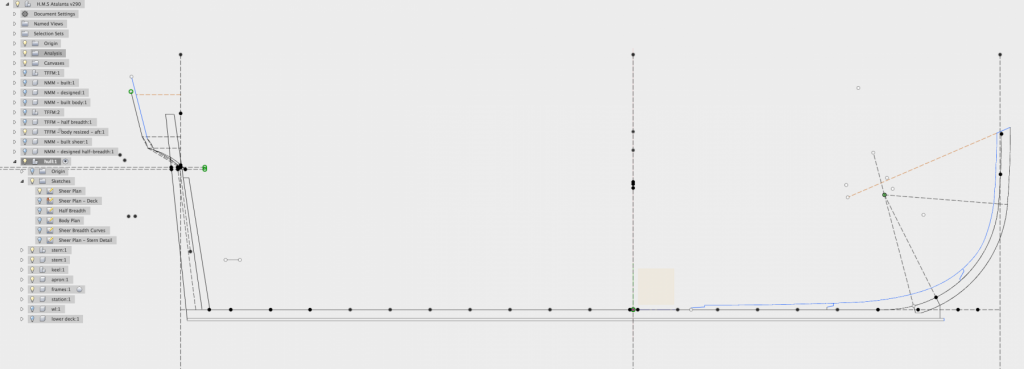
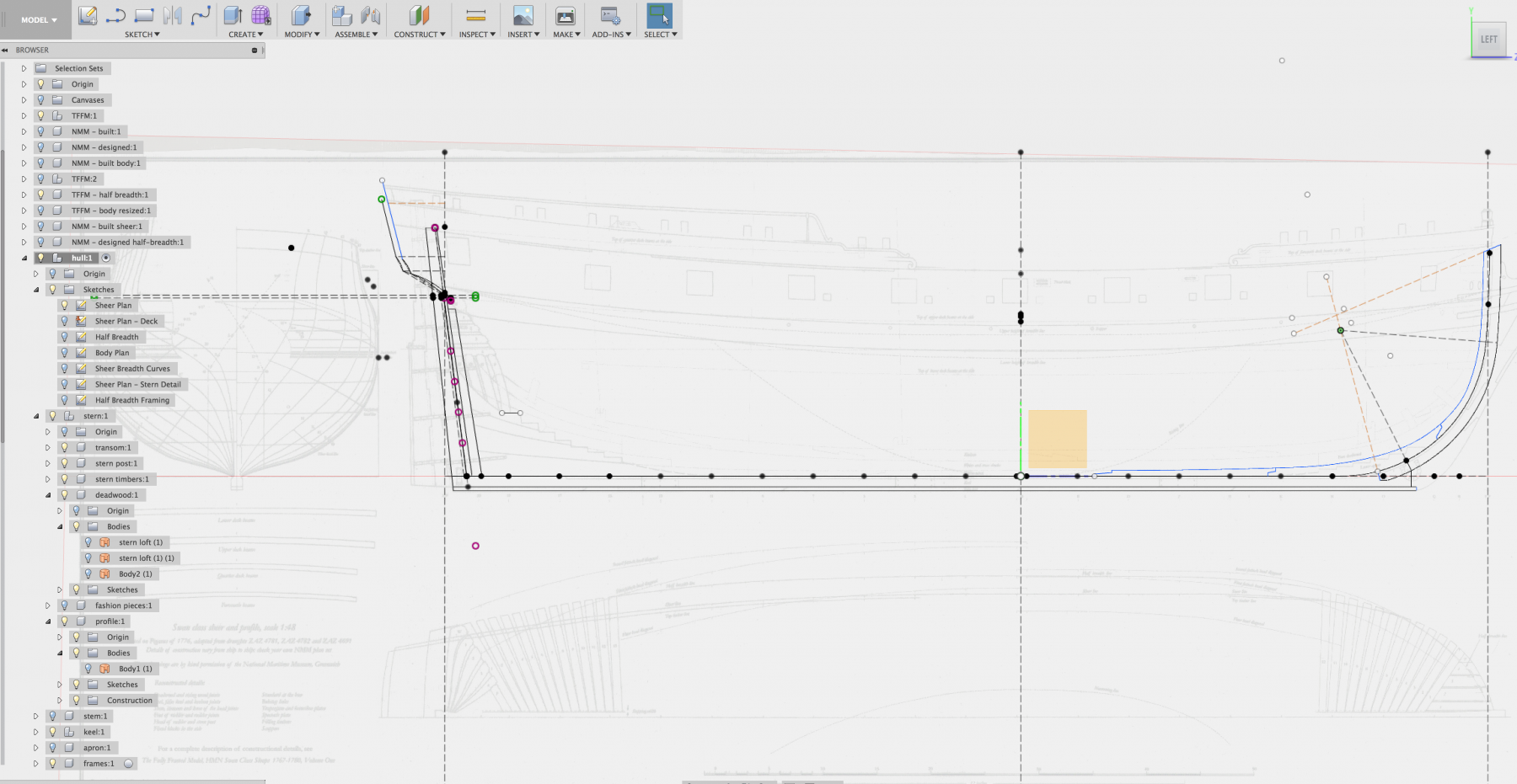
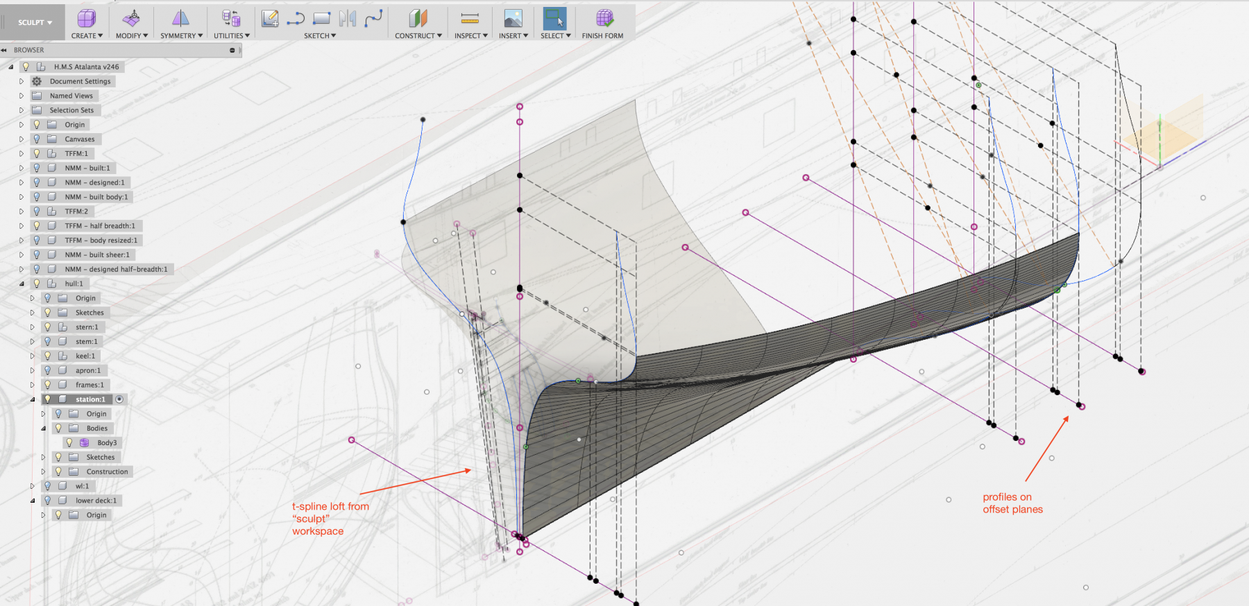
After a few transatlantic flights, I've managed to the roughly sketch body plan across the relevant planes set along station lines. I ended up going back to the patch workspace instead of t-splines as the ability to edit edit and adjust far out-weights the smoothing ability. I've ended up using projected points from the relevant half-breadth and sheer sketches combined with construction lines to establish bounds of the geometry. Unfortunately it looks a little noisy in the screen capture. I tried using splines but quickly became frustrated and went back to using arcs and tangent constraints. Originally I used 4-5 arc segments for some but once I discovered the zebra analysis and repeatedly adjusted the curves for fairness, it became apparent that as few arcs as possible will result in improved fairness. While still can be improved, if I keep continuing at this point i'll be spinning my wheels until I'm able to model other areas. Which brings me to how to bridge the stern post, station 20 up through the wing transom. I created construction planes using the sheer plan for the bottom of the wing transom, transom #1 - #4, and one in between the keel and the bottom of #4. I then created sketches on these planes. This adds some complexity as projections will be skewed when looking down towards the top of the keel. I added the various reference points and intersected the stern post at each sketch. However, a rough sketch of the filling transoms (?) profiles appear way off from the TFFM half breadth plans. I've struggled making the 15" square at head of the stern post fit the rest of the plans. TFFM states 1' 3" on pg. 41, pg. 64. However, the plans seem to agree with about 12". Additionally, the contract I have for the Hornet states: "The stern post to be of good wound? oak tim of the best kind free from defects. sq. at head 12 1/2 (which is t run up to bolt in the Lua? deck beam)" Which leads credence to the ~12" dimension. Does anyone have thoughts on regarding this? This screen shot is taken top down which means the profile lines for the filling transoms are project per the angle of they're drawn on.


-
H.M.S. Atalanta - Drafting my own plans
Ben752 replied to Ben752's topic in CAD and 3D Modelling/Drafting Plans with Software
Thank you for pointing this out. I plan to go back and alter them but wanted to keep it simple as I work through the various components. -
H.M.S. Atalanta - Drafting my own plans
Ben752 replied to Ben752's topic in CAD and 3D Modelling/Drafting Plans with Software
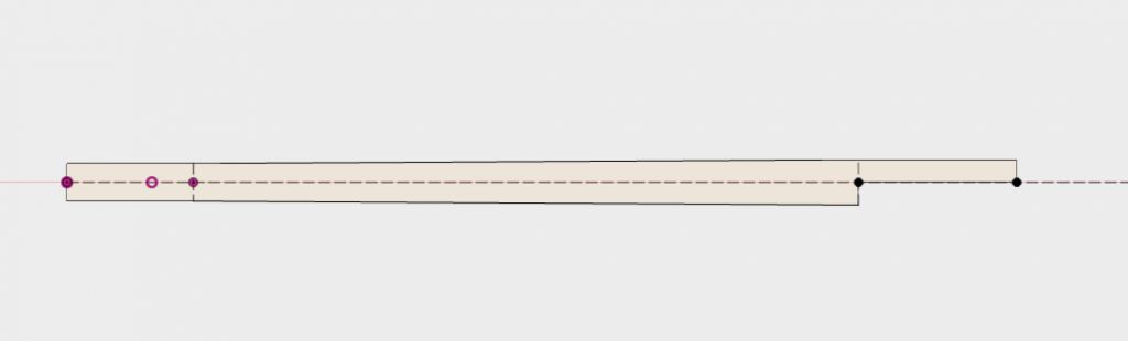
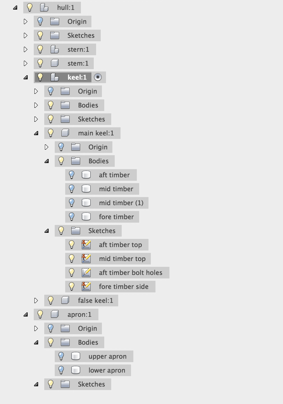
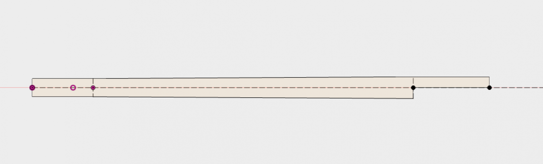
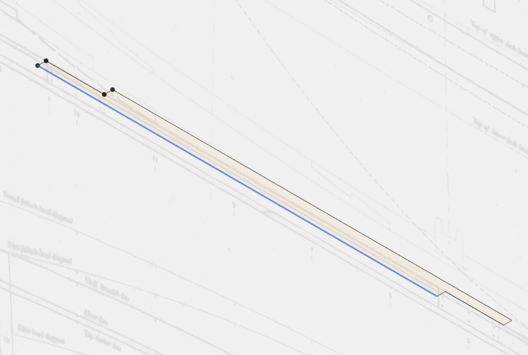
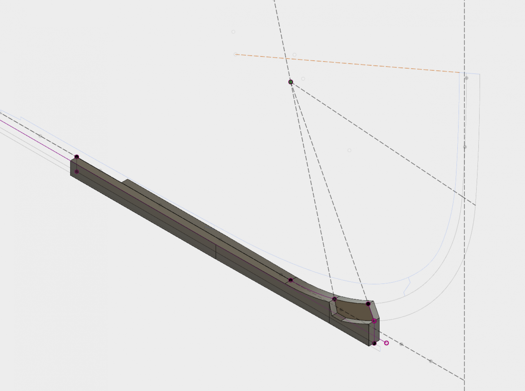
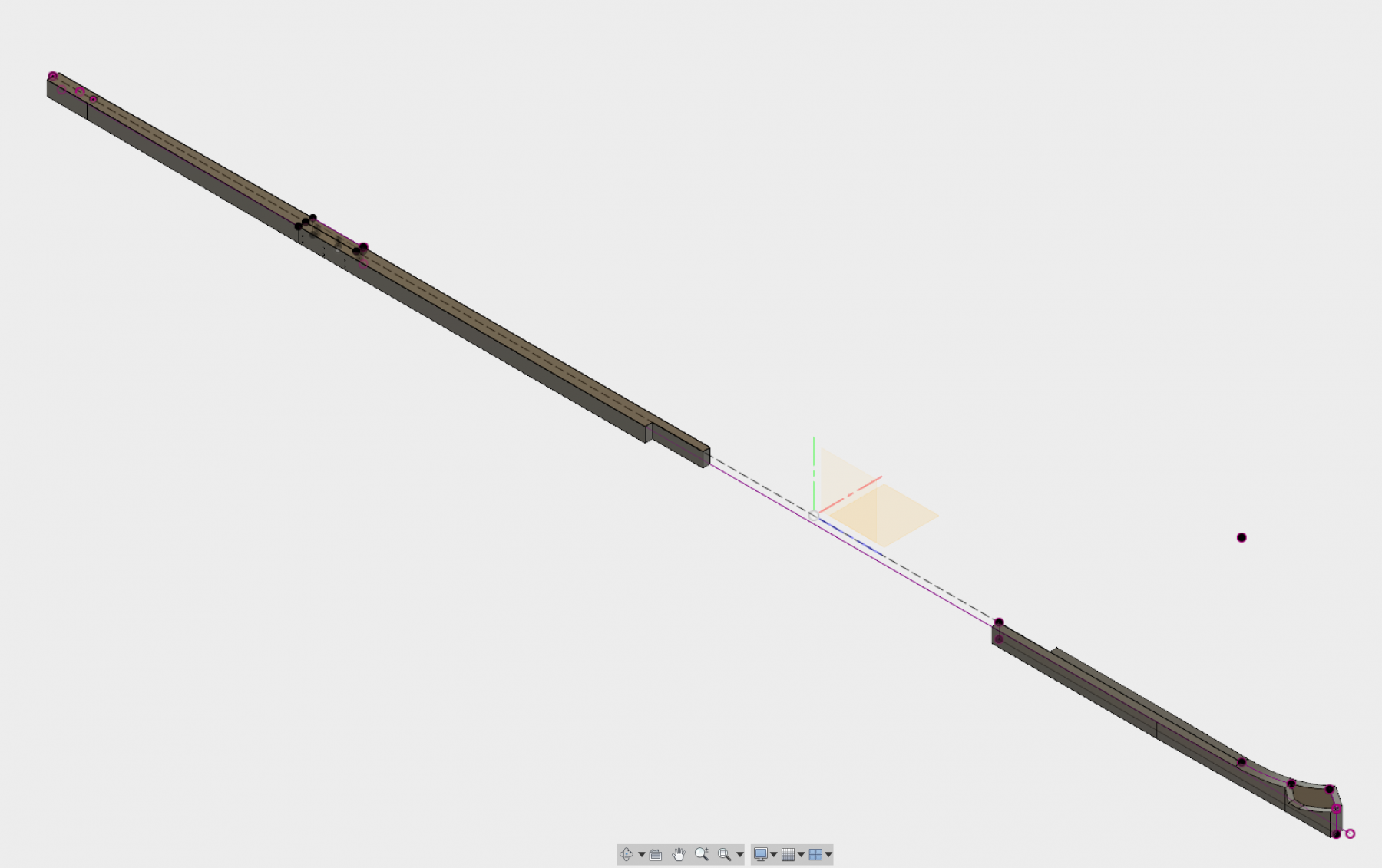
When I initially started this project, I started down the path creating a 3d model in Fusion following the order of the book. It quickly became apparent that this strategy is not an optimal way of working. However, the work below on the keel is fairly simple and was able to be salvaged before I shited to following a construction order closer to what is described in Steel. The process used is as follows: 1. Under a new component create separate sketches for the fore, aft and a middle timber of the keel. 2. The top plane worked well to construct the aft and middle sketches as it lends itself well to a extrude along the Y axis. Because the mid keel components are repeated, I repeated the component using the rectangular pattern feature. This gives me a reference edge to project in the fore timber sketch with the added bonus of propagating tweaks forward. 3. On the fore timber, I constructed the sketch using the left side plane as it allows for projecting the arcs of the stem to model the the boxing. Whenever possible, I"ve used projections off of one of my "master" sketches to allow for propagation of changes to the bodies that model the timbers. 4. To create the simplified boxing joint I created the sketch for the lower stem on the left plane, extruded on one face left face to 1/2 the thickness and used the combine/cut option on the fore keel. Then did the same on the other side but make the fore keel the cutting tool.

-
H.M.S. Atalanta - Drafting my own plans
Ben752 replied to Ben752's topic in CAD and 3D Modelling/Drafting Plans with Software
These have really thrown me off. I started tinkering with this Fusion model about 5 months ago and while I was able to make some progress in the drafting, I would hit a spot where dimensions would be way off and I"d start second guessing everything. My natural inclination is to stop and review my work, and years of technology work has taught me to exhaust all explanations of issues using my own work before second guessing the work of others. However, I have found that the body plan on the TFFM plans appears to be inconsistent in some areas. Last week the use of the diagonals clicked and made a strong case the plan does seem to be off (incidentally the station on the designed and built draughts are very close to where i've drawn the curve). I will say that the HMS Hornet contract I found in the RMG library (outside of the plans collection) has been very useful in providing a 3rd party dimension reference. It contradicts some of the dimensions in TFFM in ways that appear to be consistent with the draughts. For those that are interested, http://collections.rmg.co.uk/archive/objects/512680.html#uaX1DK6V18Qgr5bl.99 the hornet contract is in SPB/27 This is not a criticism of TFFM at all! -
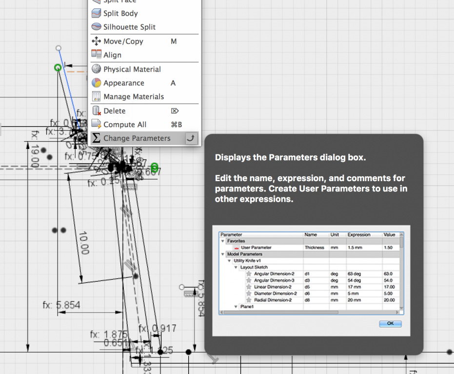
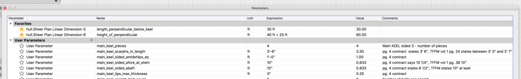
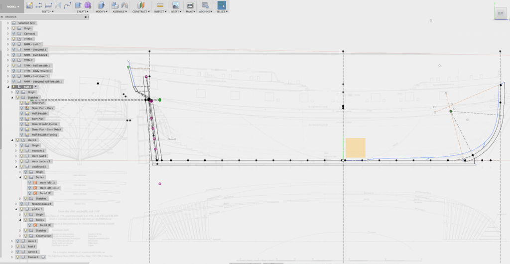
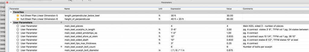
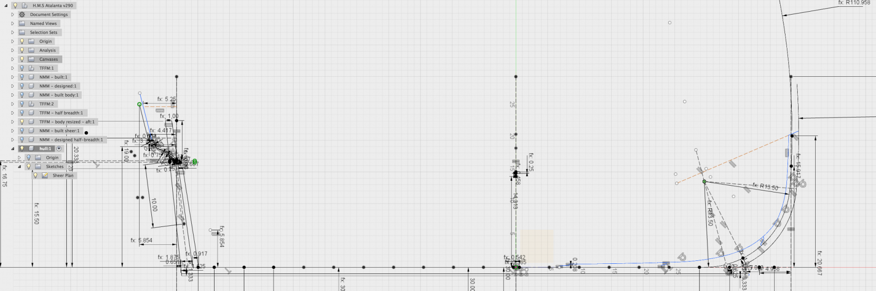
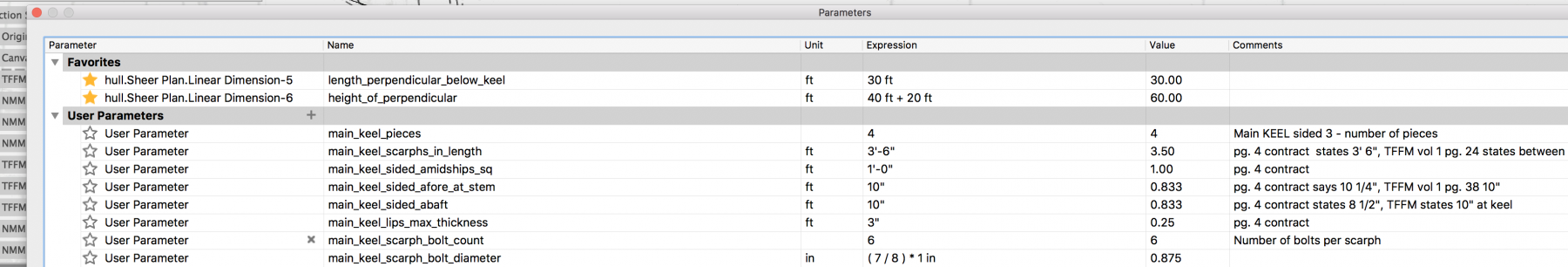
Good day everyone, I've recently moved to Edinburgh for work. My personal effects are somewhere in the middle of the atlantic (above water hopefully). This has given me time to focus on planning my first scratch build, the H.M.S. Atalanta. I've selected this ship due to the wealth knowledge in the TFFM series, availability of contemporary plans from Admiralty models, historical plans and many build logs. The hope is that with all of this information, it will give me enough information to stumble through the creation of plans using CAD and construction of the ship to a high level of quality. I'm using Fusion 360 as my CAD program due to it's excellent price (free for hobbyist), professional quality and integrated t-spline, anlysis tools, parametric modeling features and CAM support. I have made several false starts on the plans as Fusion is stew relatively new to me. One of the trickiest things is getting a good scan of the draughts into fusion and scaled. When you can zoom in to miniscule details of the draughts it becomes apparent how warped and skewed they are. One technique that I've found useful in fusion, is that when using the "attach canvas" that if you first create a component, you can then duplicate the component and translate it. This is quite welcomed after you go through the laborious process of aligning and rescaling the draught. To start off, I've made a considerable effort to follow the practices outlined in Steele. The dimensions have been sourced through a contract I found for the HMS Hornet at the RMG and the TFFM books. When there is a discrepancy I've sided with the TFFM as the books are my guide. My effort is to not trace but rather draft using a combination of traditional methods and 3d approaches. Given this, the sheer plan is first up. In Fusion, I've created "primary" sketches for each major major plan with the exception of more detailed aspects (following the order of Steel lends itself well to this approach). For more detailed areas, I then create a separate sketch and project or intersect the references needed. Fusion prefers this approach as it runs faster and easier to apply constraints and such. For starters, here are my sheer sketches. Below is the sketch in edit mode so the dimensions are visible (when zoomed it the dimensions are more manageable). I've found using custom parameters exceptionally useful for cataloging scantlings and the source reference material I used.

-
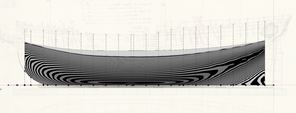
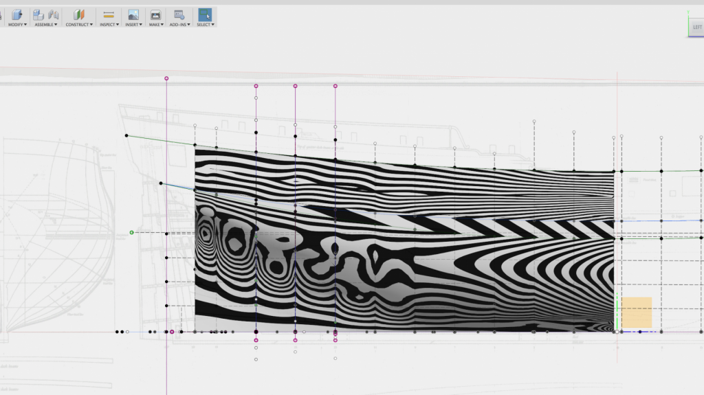
The zebra analysis tool also has been quite useful in getting a feel for the cursory fairness of the hull.
-
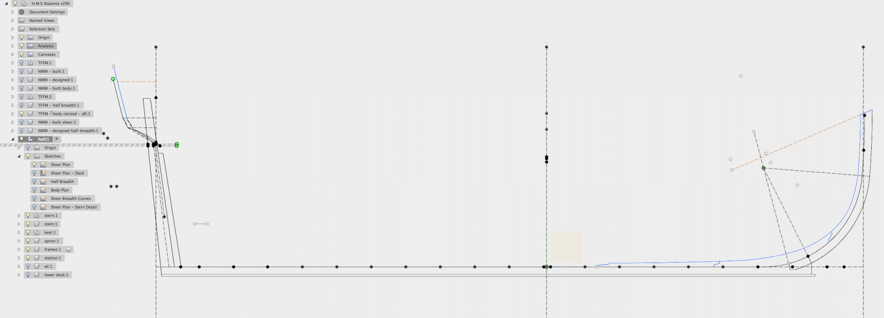
The approach I've taken so far follows something like this: 1. Draft the sheer plan on a sketch following the approaches outlined in Steel. I've been using model parameters to define the scantlings to support changing values easily. The description has been very useful for providing traceability. 2. Create a half breadth & body plan sketch. 3. Start building up additional detail on subsequent sketches on the same plane as the sheer, e.g. deck curves, transom details, etc as it seems fusion works best with more sketches with fewer details. 4. Build up the profile of the hull using offset planes at station intervals with sketches representing the details of the body plan. While I originally used the patch workspace loft command, the t-spline (from the sculpt workspace) loft allows for more flexibility in fairing.
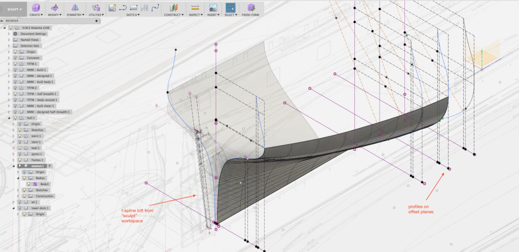
-
Swan class 3D model in progress
Ben752 replied to dvm27's topic in CAD and 3D Modelling/Drafting Plans with Software
Looks fantastic Greg! Will there be anyway to see measurements in the 3D model? I hope the Hornet contract was useful. Looking forward to getting this to help with my future Atalanta build.- 104 replies
-
- 3
-
-
- pof swan series
- swan
- (and 1 more)
-
I was looking to get a 4 jaw sometime this year but given their prices rarely are discounted it looks like I'll be getting one this month. https://www.sherlinedirect.com/index.cfm?fuseaction=product.display&Product_ID=1507&CFID=140895239&CFTOKEN=82798041
- 1 reply
-
- 2
-
-
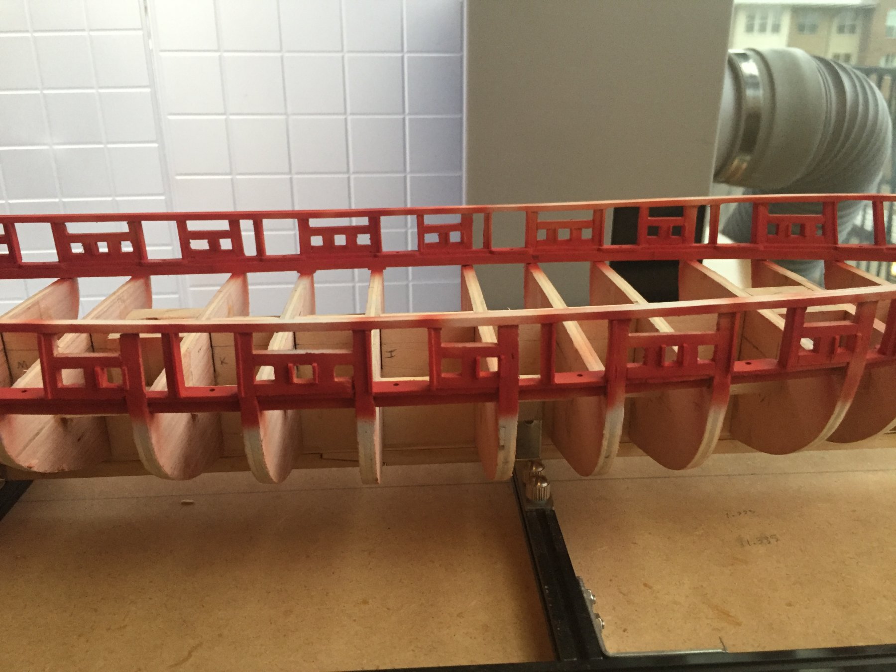
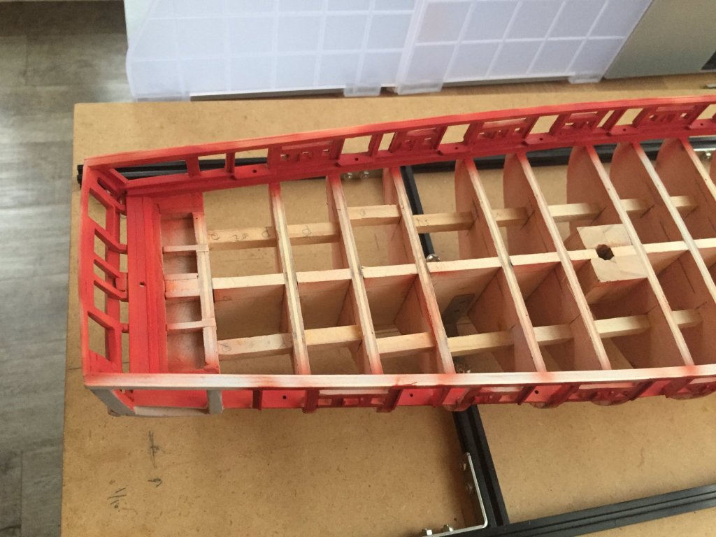
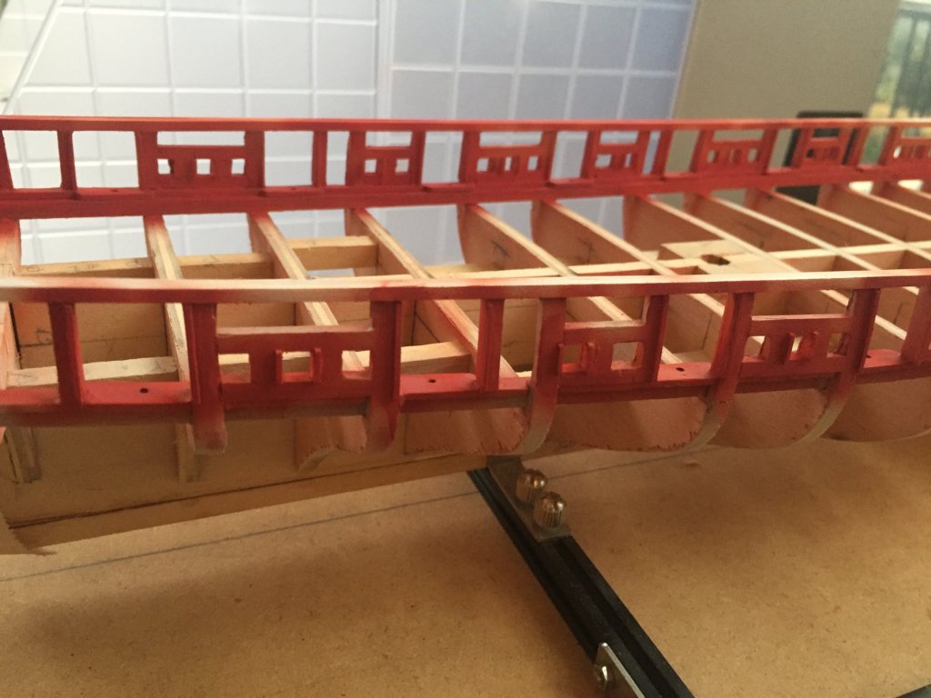
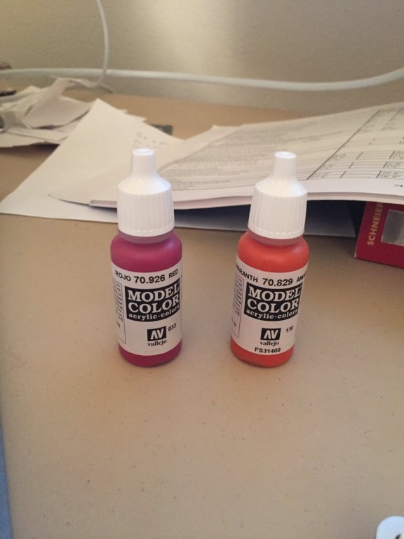
Next, i've framed the supports for the top rail. I found that using multiple thinner pieces of stock allowed for a nicer curve along the bow. No steam bending necessary when using thinner stock as well. Sadly, I failed to capture any photos of the laborious process of framing the gun ports. I also used the same technique as xken of using 1/32" square stock to mimic the inner surface of the gun ports and sweeps. Now onto the body work. I sprayed 2 coats of the Vallejo grey urethane primer with my airbrush and sanded between coats using 400 grit 3M ultra flexible . Additionally, I used the bondo spot putty on the inner side of the gun ports to even the surface and hopefully give the appearance of a single board through the full width. I attempted to color match the red from various photos and settled on the following: 1. 5 parts Vellejo red 2. 6 parts Vellejo amaranth red 3. 1 part flow improver 4. 3 parts thinner First coat is applied, I'll sand then shoot another 1-2 then apply a matte varnish (again, another fantastic xken tip).
.thumb.png.a8cca26ae5d0712e0e1b60fc40aa27ef.png)
.thumb.png.6d6350746dffc0412bca089710262af7.png)
.thumb.png.61bdf7adb08684e493193cfd40e632da.png)
.thumb.png.c30265f9e619eb8f382cd2f9c8be0699.png)

- 18 replies
-
- 3
-
-
- niagara
- model shipways
- (and 1 more)


.png.a822a1c7756421949a227a9325a3569e.png)
.png.7cc0ffcc46fa230d9f8f7ecfbc5e6e32.png)
.png.07708e8f220fbef9d410bbdd82344323.png)
.png.2c43257ff24a51add98cf07542d7e8b9.png)