Shore thing
-
Posts
72 -
Joined
-
Last visited
Recent Profile Visitors
713 profile views


-
 Harvey Golden reacted to a post in a topic:
Breezin Thru by Shore thing - FINISHED - Wye River Models - 1/2" scale
Harvey Golden reacted to a post in a topic:
Breezin Thru by Shore thing - FINISHED - Wye River Models - 1/2" scale
-
Mike Collier reacted to a post in a topic:
Skipjack by Shore thing - FINISHED - Wye River Models - Scale 1/2" - First wooden ship build
-
Ryland Craze reacted to a post in a topic:
Breezin Thru by Shore thing - FINISHED - Wye River Models - 1/2" scale
-
Ryland Craze reacted to a post in a topic:
Breezin Thru by Shore thing - FINISHED - Wye River Models - 1/2" scale
-
Roger Pellett reacted to a post in a topic:
Breezin Thru by Shore thing - FINISHED - Wye River Models - 1/2" scale
-
GrandpaPhil reacted to a post in a topic:
Skipjack by Shore thing - FINISHED - Wye River Models - Scale 1/2" - First wooden ship build
-
GrandpaPhil reacted to a post in a topic:
Skipjack by Shore thing - FINISHED - Wye River Models - Scale 1/2" - First wooden ship build
-
GrandpaPhil reacted to a post in a topic:
Breezin Thru by Shore thing - FINISHED - Wye River Models - 1/2" scale
-
GrandpaPhil reacted to a post in a topic:
Breezin Thru by Shore thing - FINISHED - Wye River Models - 1/2" scale
-
GrandpaPhil reacted to a post in a topic:
Breezin Thru by Shore thing - FINISHED - Wye River Models - 1/2" scale
-
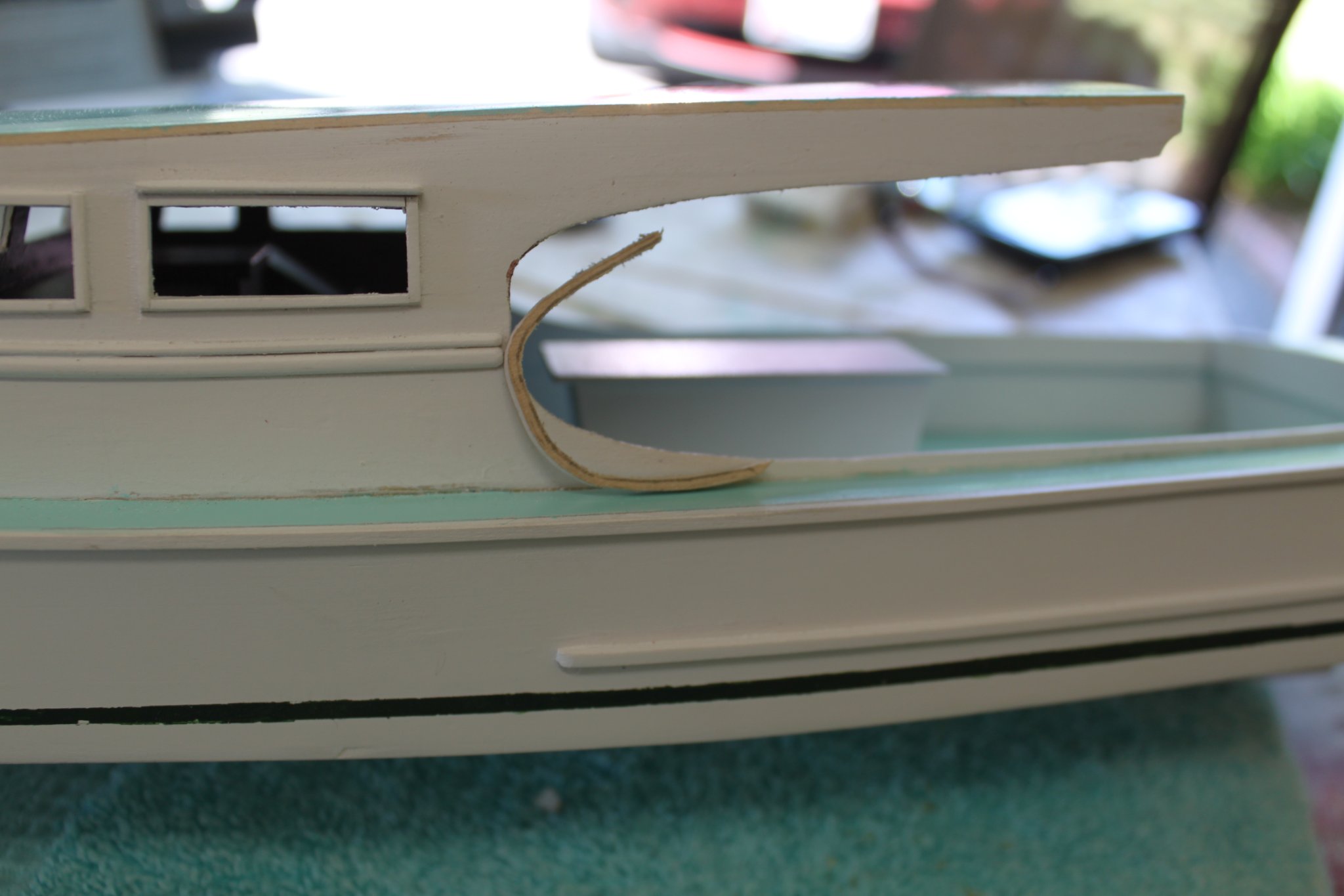
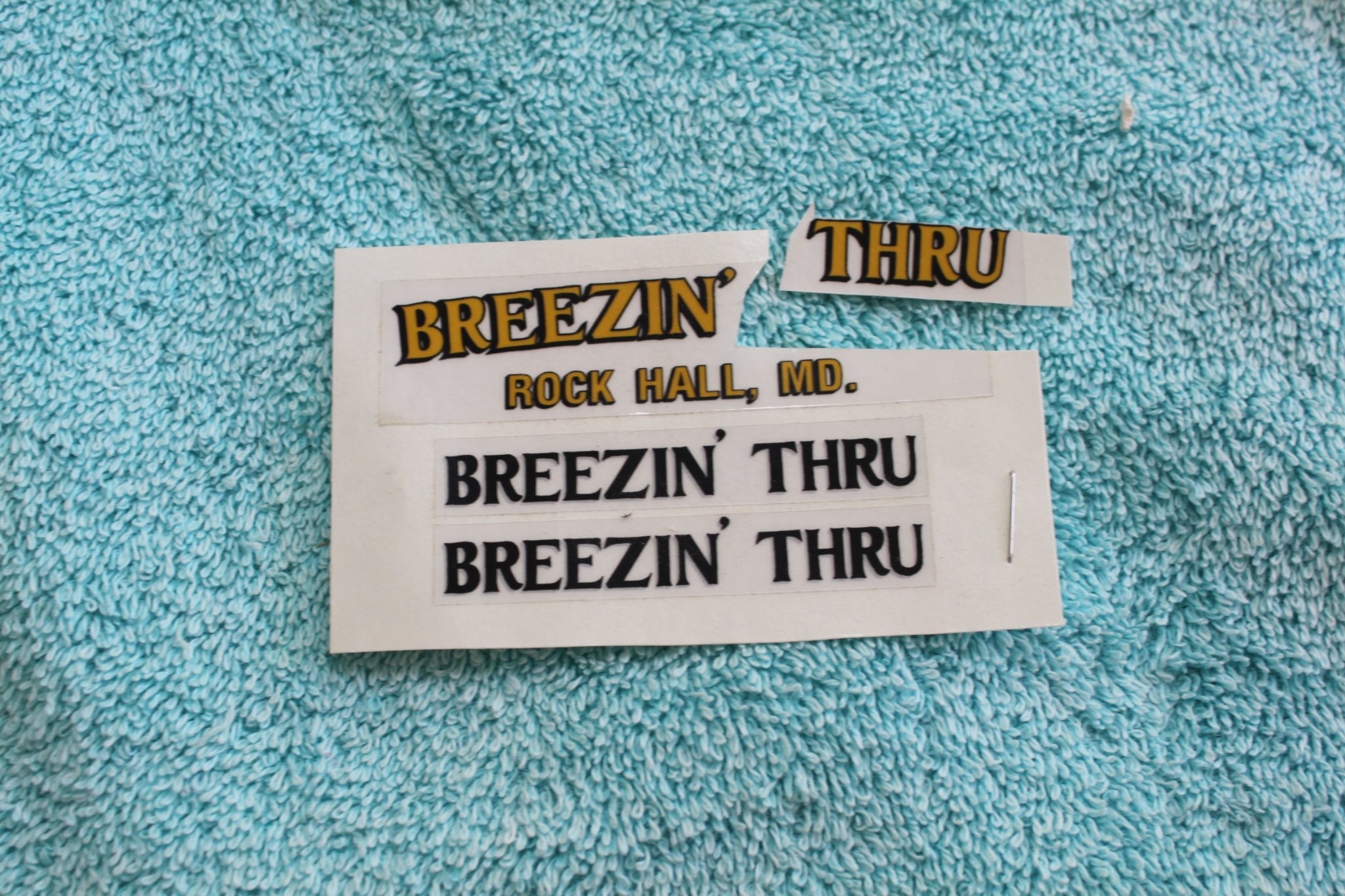
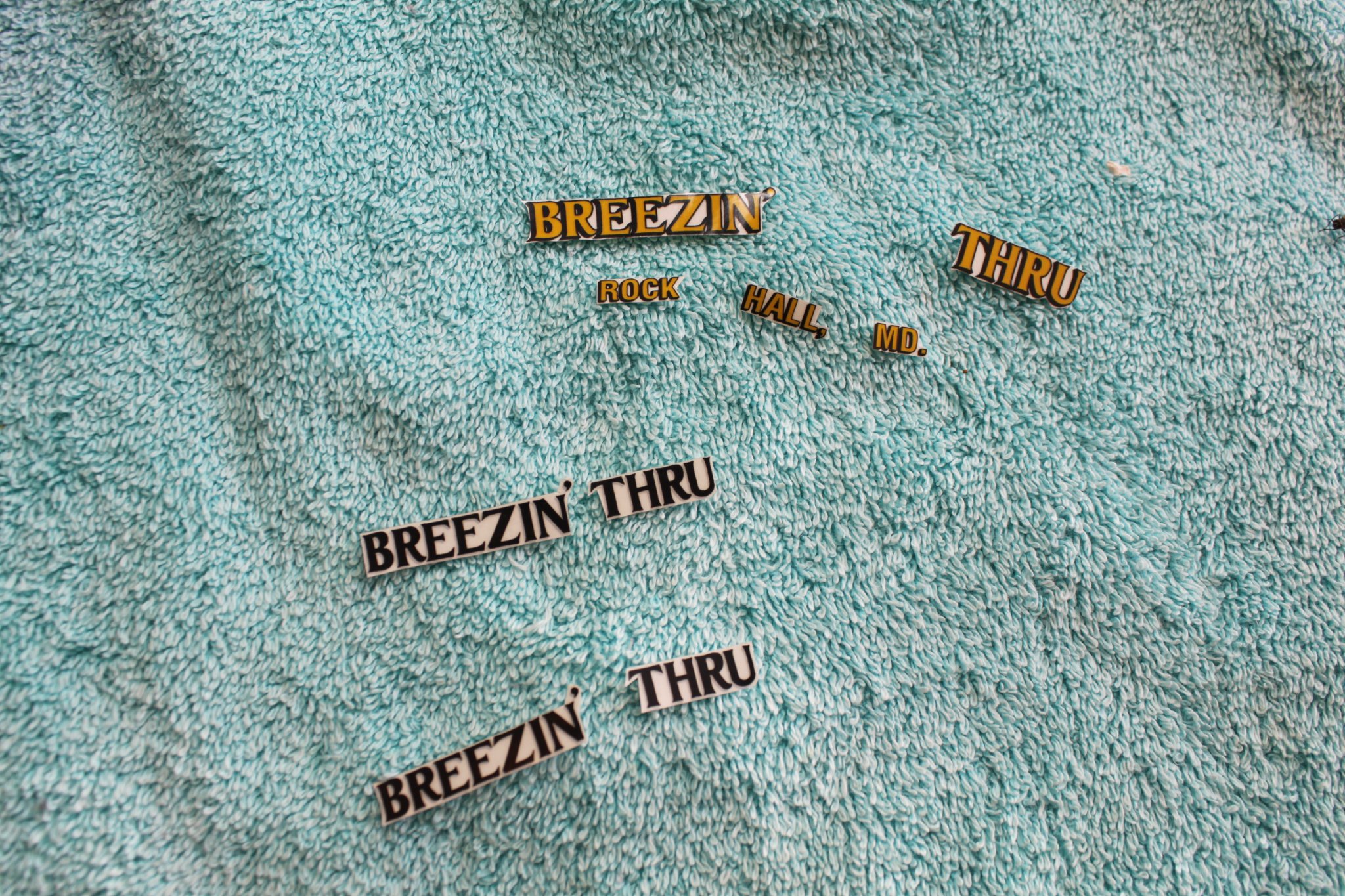
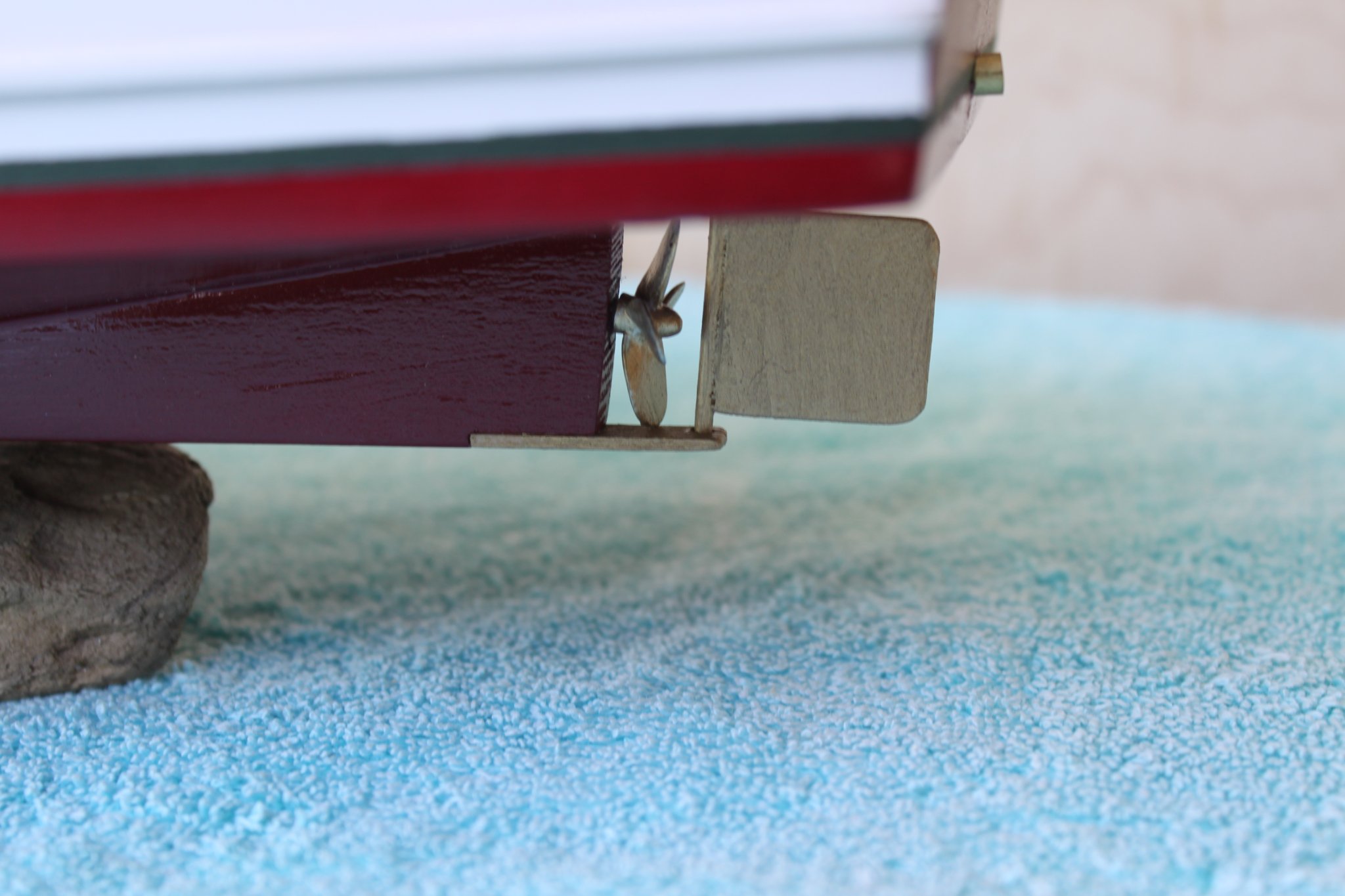
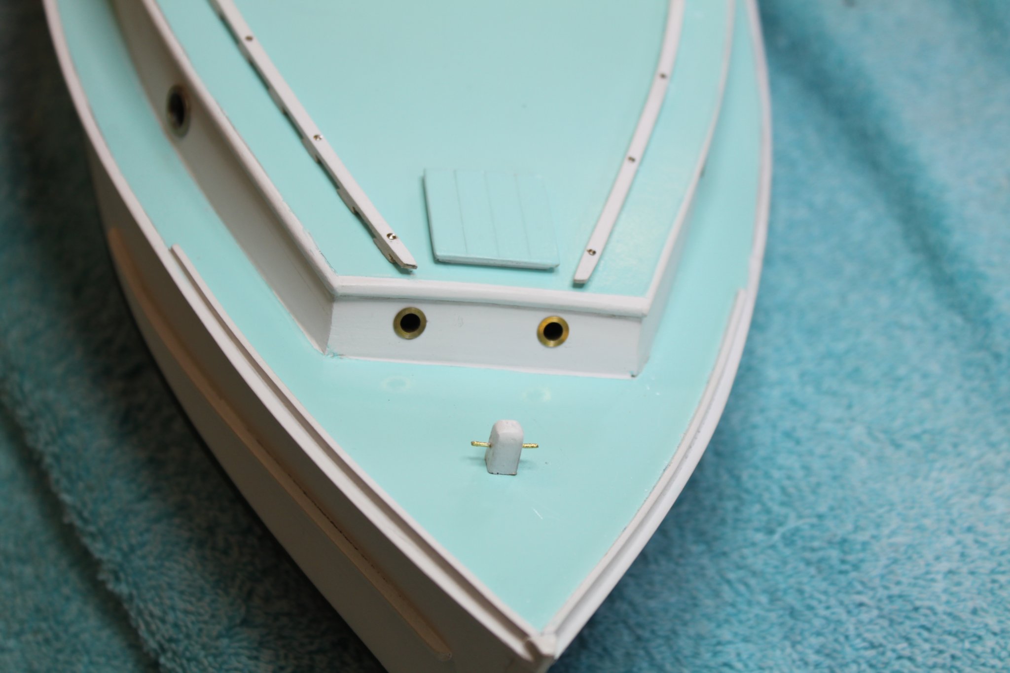
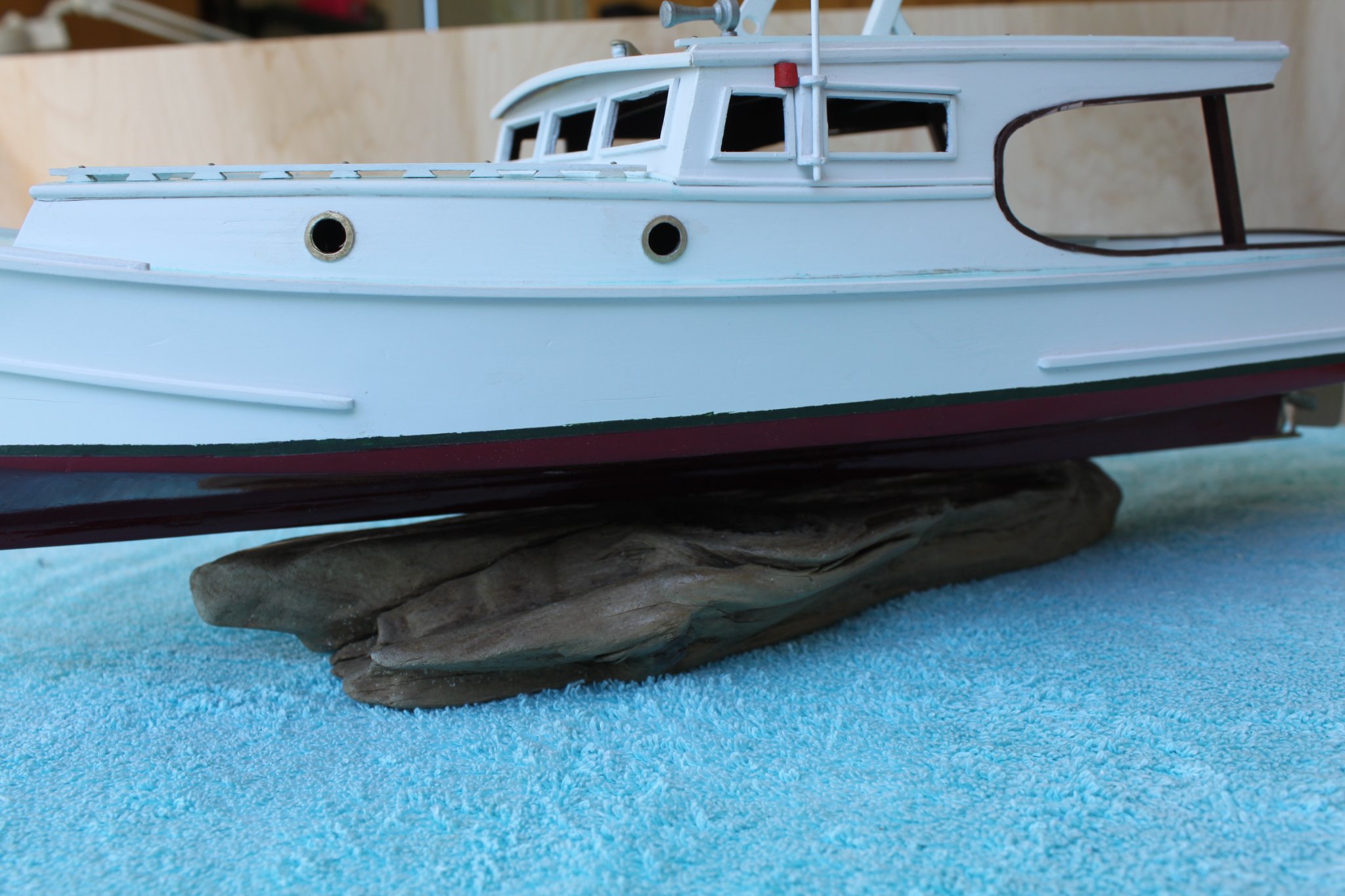
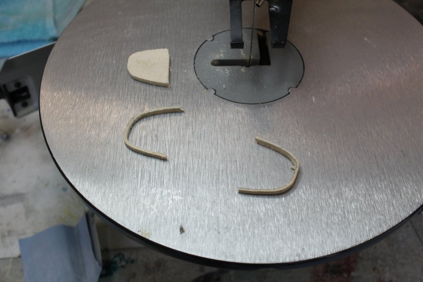
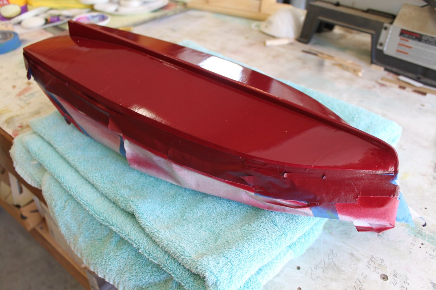
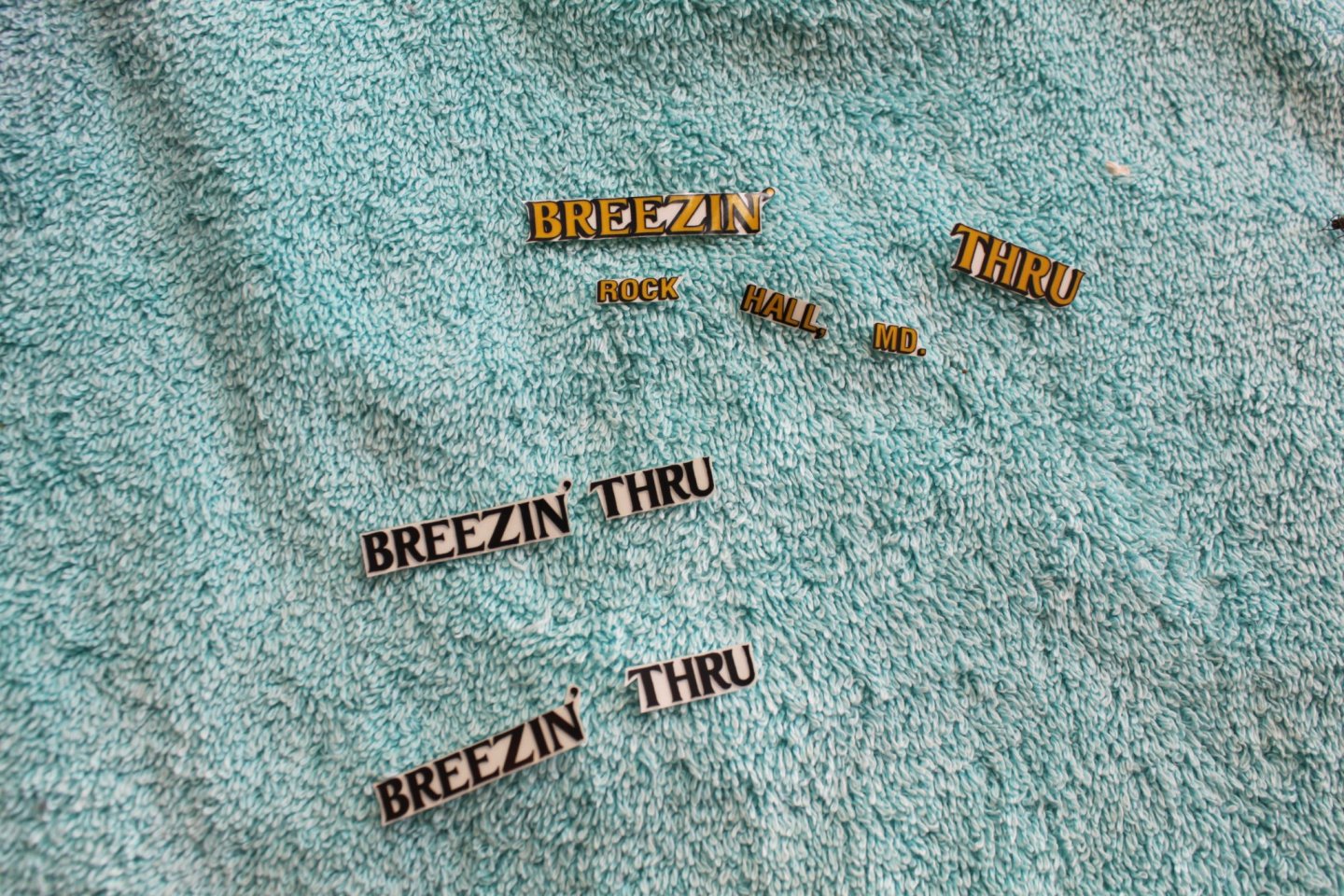
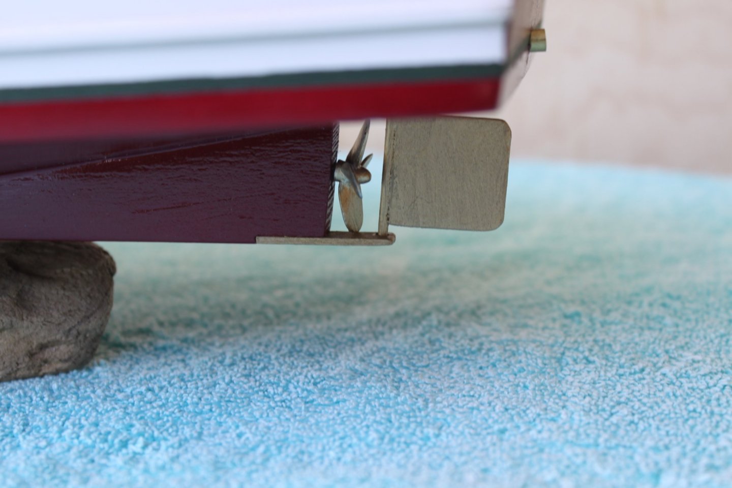
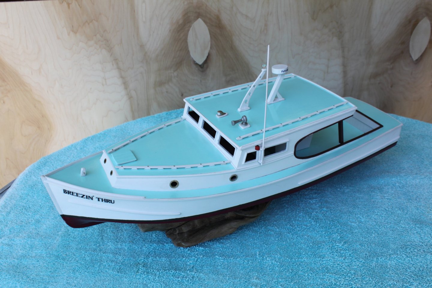
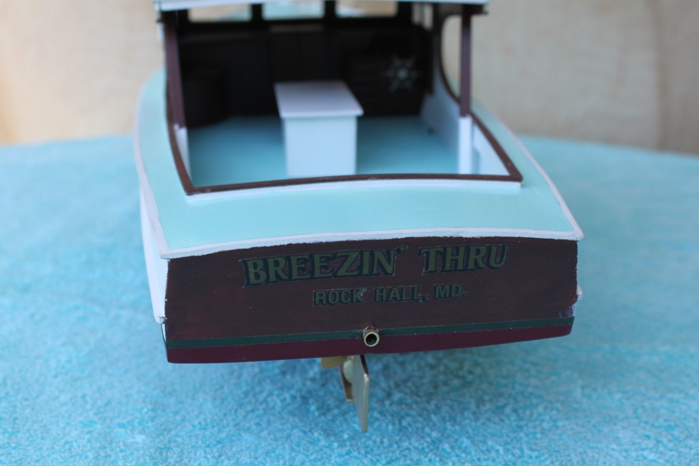
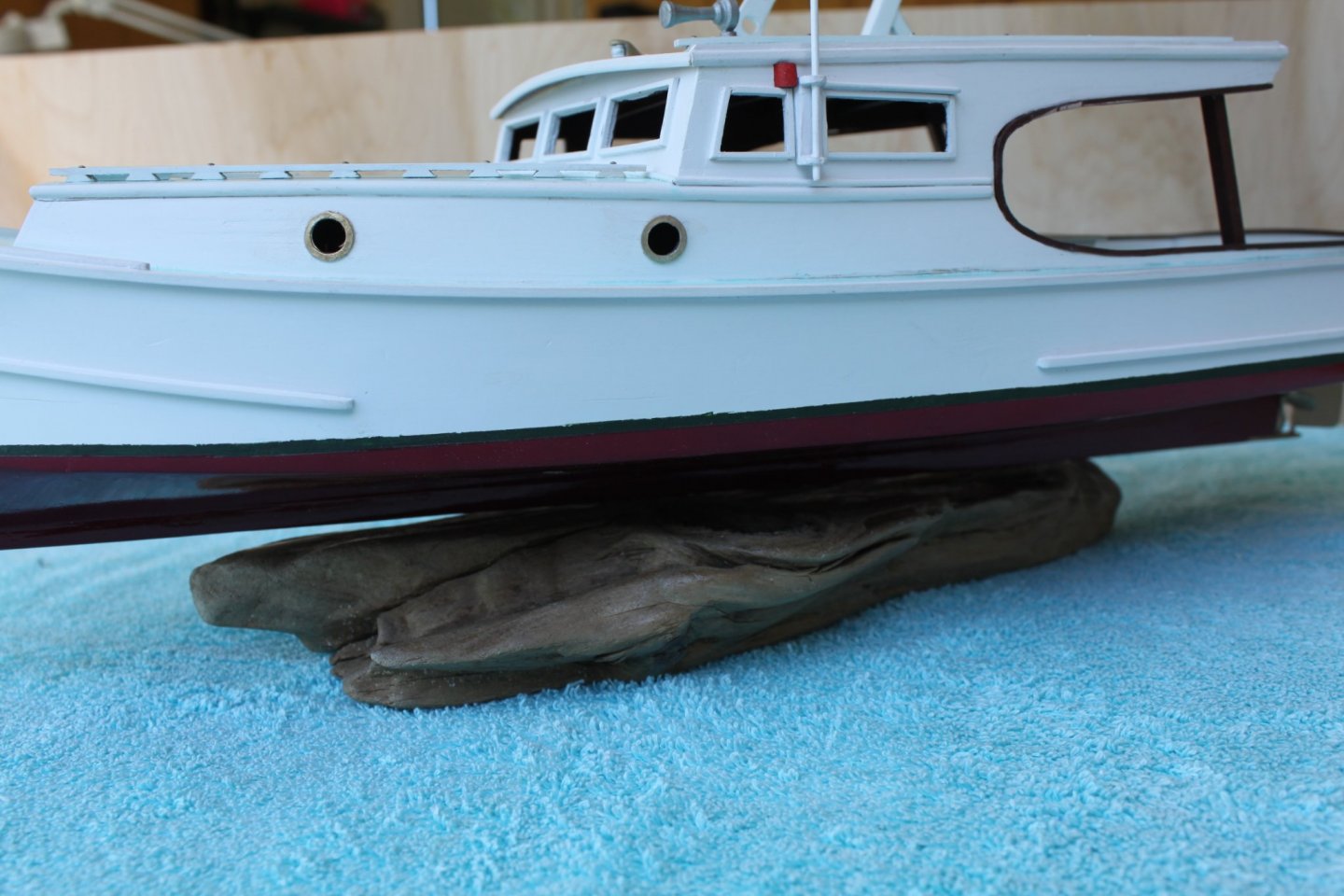
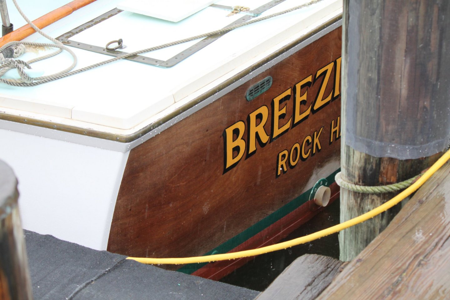
For those of you with keen eyes, I'm sure that you have noticed that some of my pictures are out of order in relation to the work I'm discussing. It is mostly because I wasn't as diligent in the photography aspect as I should have been. Sorry. As usual, my painted line didn't turn out as crisp as one would hope. I'm not sure why. The paint I used took several coats to cover sufficiently so maybe it was to thick. Perhaps I didn't let it dry long enough, who knows. With that frustration, I decided to let it dry for several days before addressing a solution and moved on. I needed to make a cap that went around the cockpit and the underside of the roof. It would be painted the same color as the helm and transom. I tried soaking the thin strips in ammonia for several days before attempting to bend them but they just kept breaking. My remedy was to glue two pieces of 1/16 sheet stock together in a plywood fashion. The curves were traced and then cut out. The picture above also shows the ragged edge of the afore mentioned boot stripe. The bottom edge will be covered slightly when the bottom paint is applied. I will tape of the worst areas along the top and re-paint them.....eventually. The rest of the cap was also cut, dry fitted, sanded and painted. With that work completed I could finally glue it into place. I am now at the point where the finishing details need to be added. A good number of them are on the roof. Clearly, I would need to finish all the bottom work while I was still able to lay the model on it's top. Here is a picture of the bottom tapped off and painted. The propeller, it's supports and the rudder were also added after the paint dried. The kit came with decals of the name and home port. Believe me, I was very glad to have them. My hand lettering skills are...not skills. LOL! As much as I was glad to have then, I didn't like the thought of all that clear plastic "adhesive" showing all around the words. My solution was to cut them out as neatly as possible. Although they looked better, they were a bit harder to apply. They will be seen in future pictures. From here a Samson post was added along with many other details. Nosing around the roof and more hand rails were attached. So was navigation lights, a horn, radar, all around light and an antenna. Once again, I used a piece of driftwood for a base. It was a good solid piece and all that was necessary to do to it was to seal it with several heavy coats of clear. The name does not stand out on the transom as well as I would have liked. It's because I went with the darker color I spoke of earlier. As you can see the home port decal is off center. It will have to do. Don't want to risk damaging the hull paint or decals. An exhaust pipe was added for more interest. There are still a few details to add and some touching up of the paint in certain areas and she will be complete. I'll save those pictures for one last post. ,


- 20 replies
-
- 8
-
-
- Breezin Thru
- Wye River Models
- (and 1 more)
-
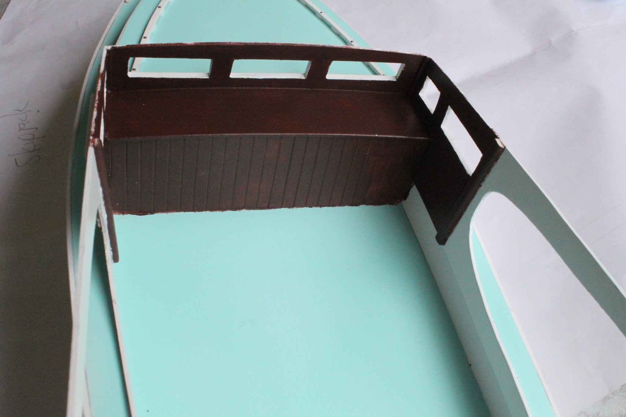
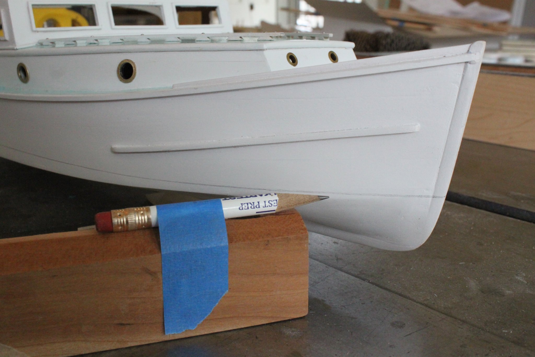
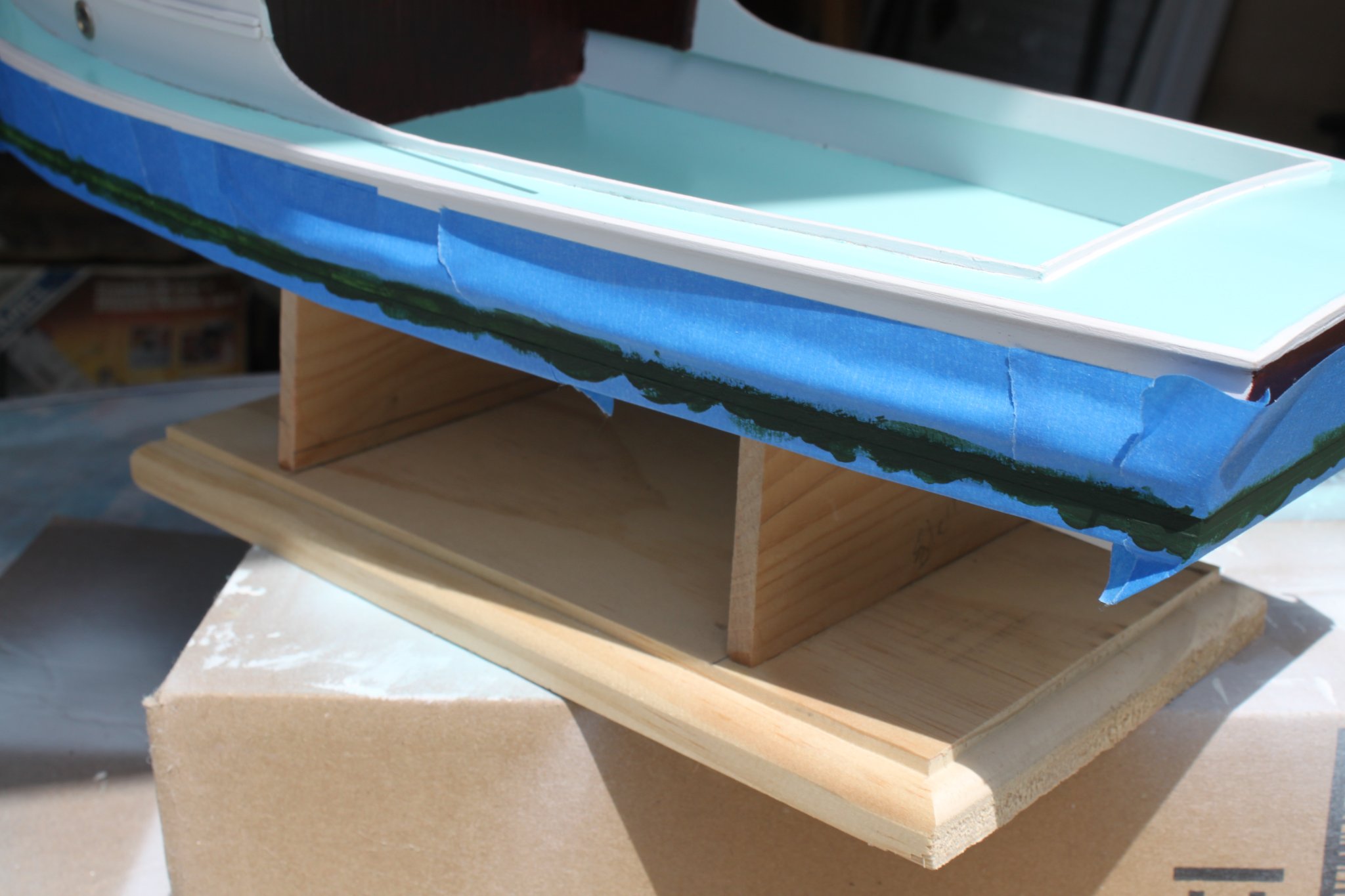
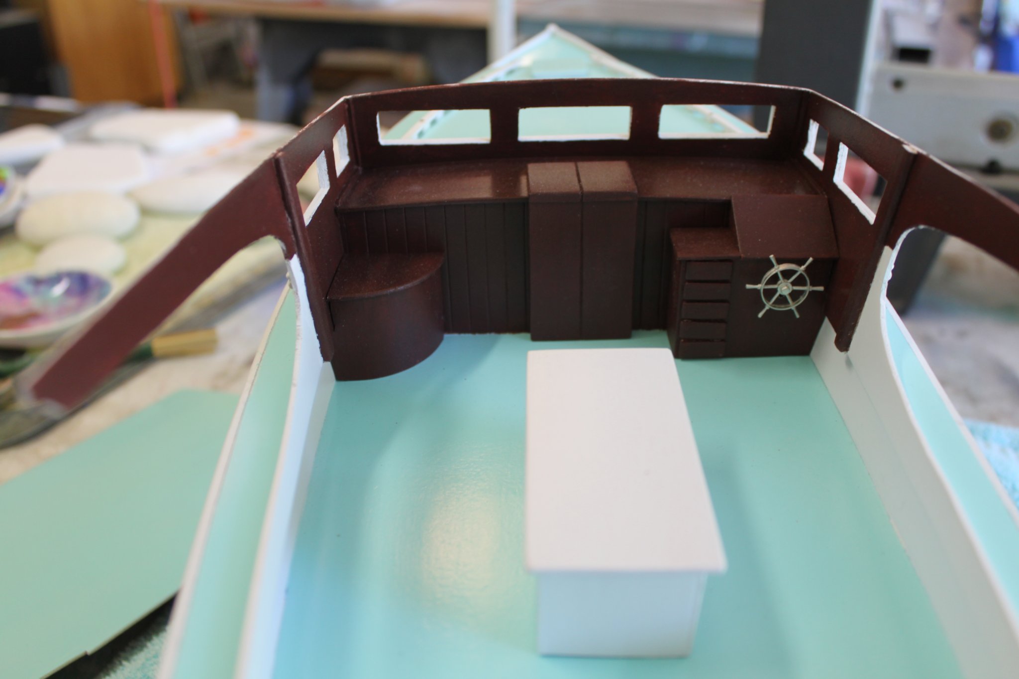
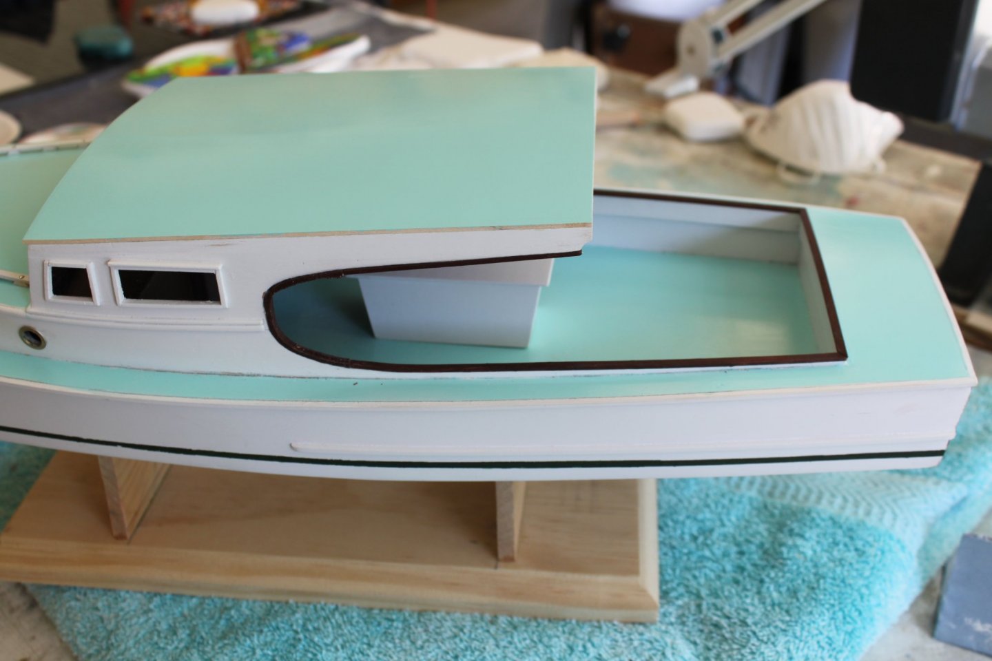
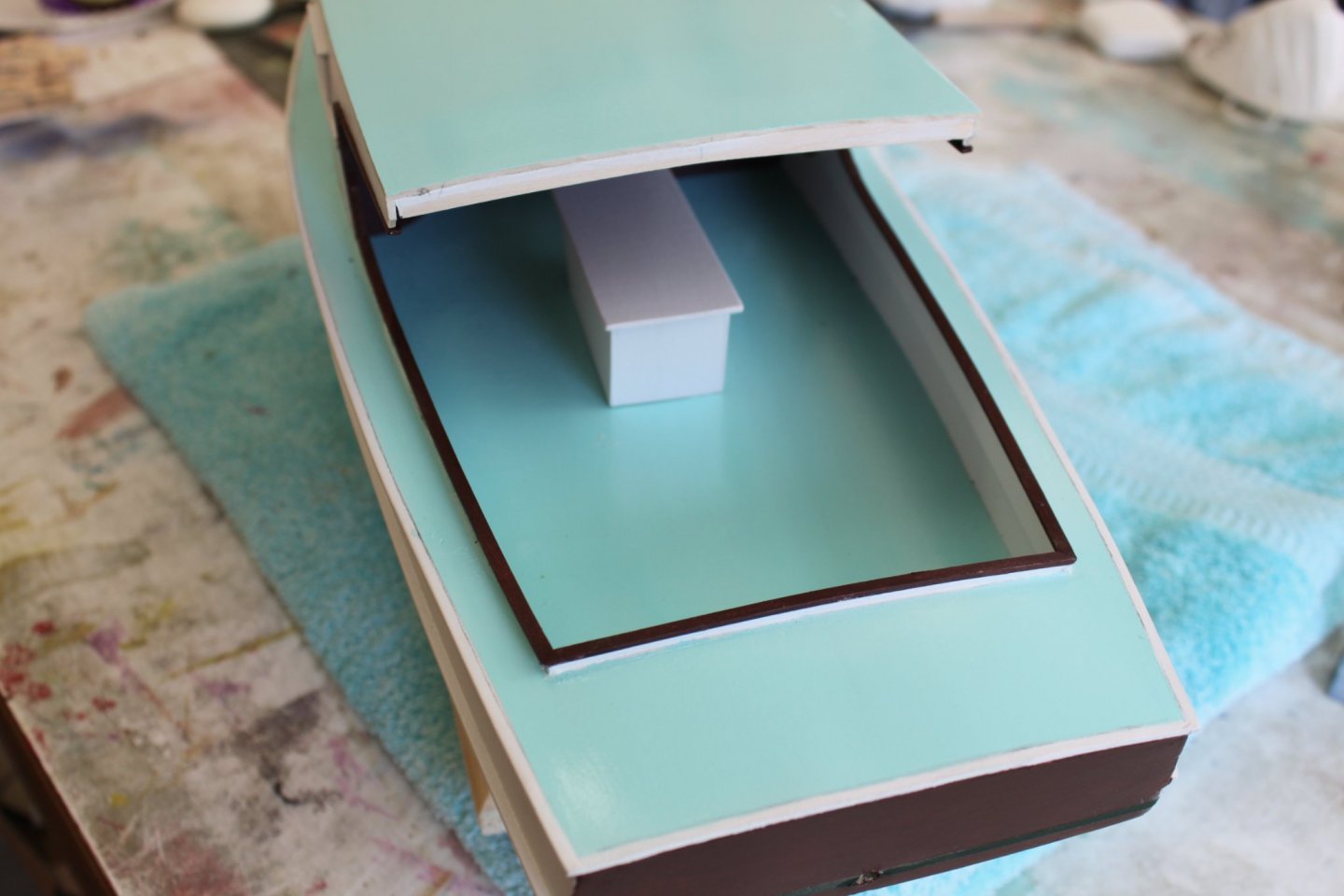
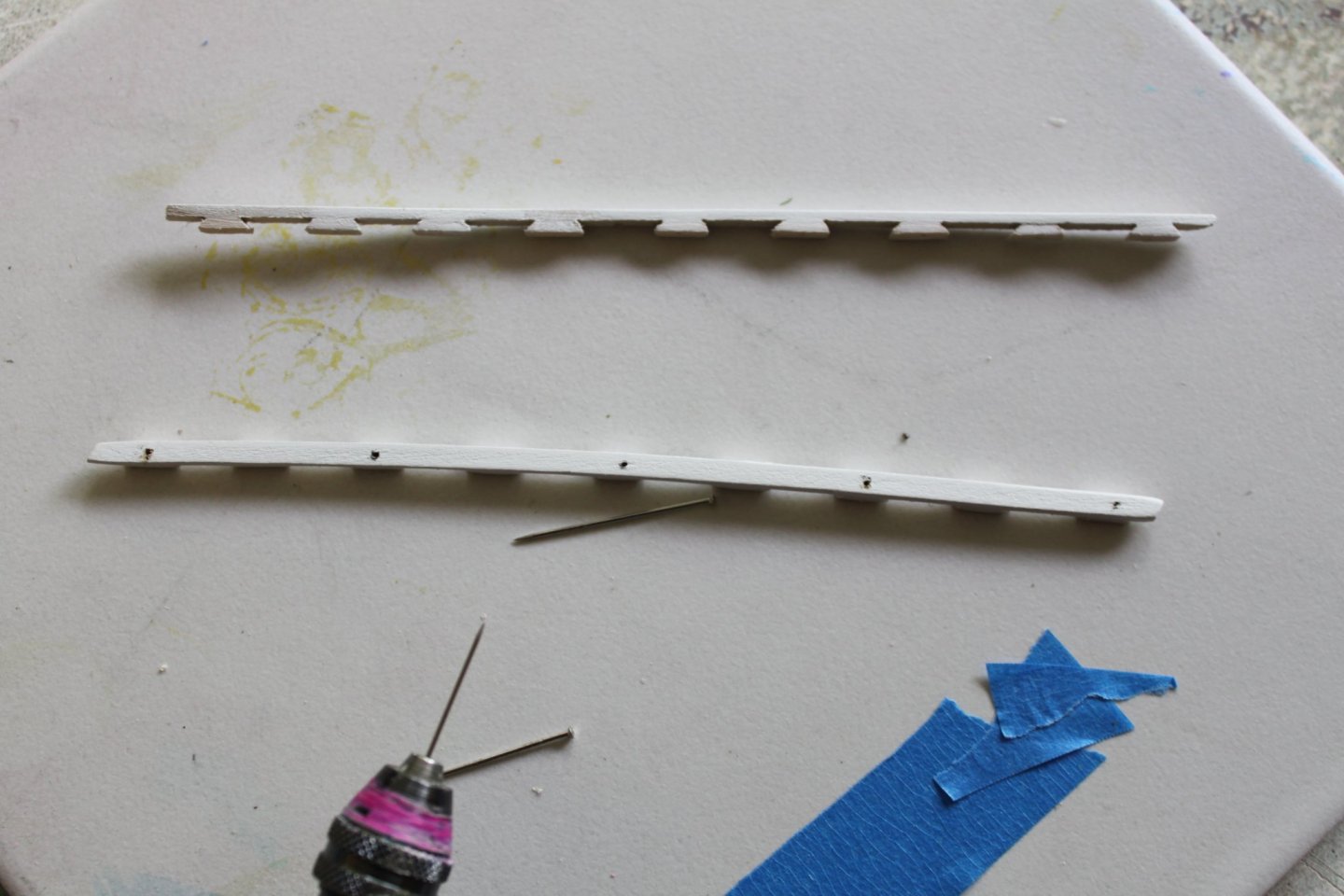
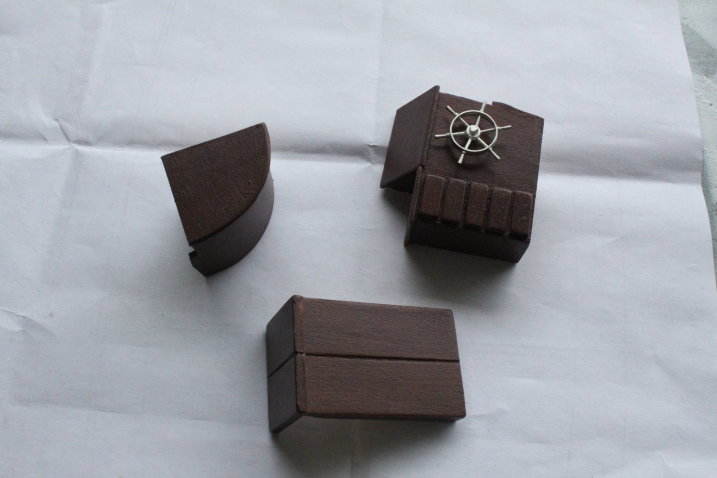
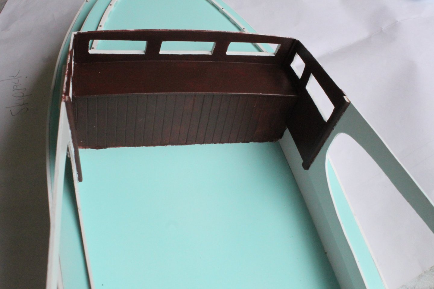
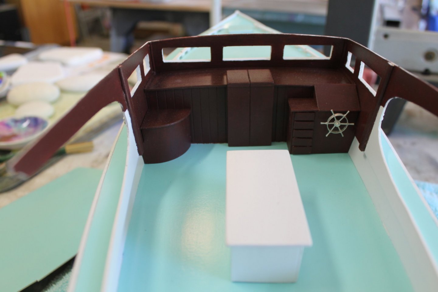
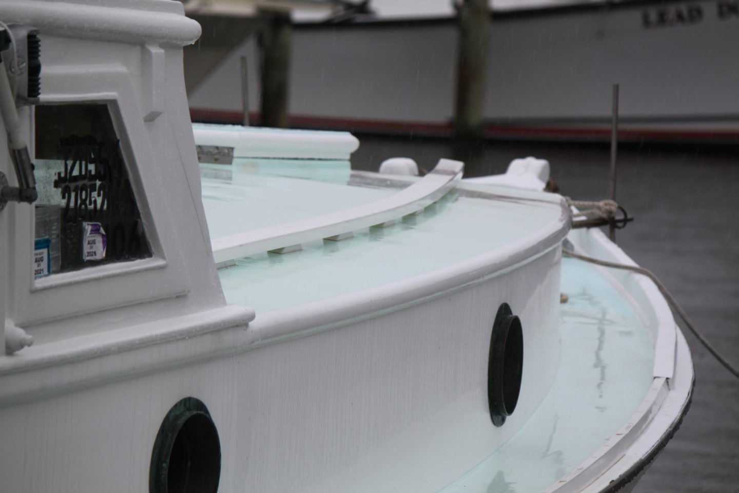
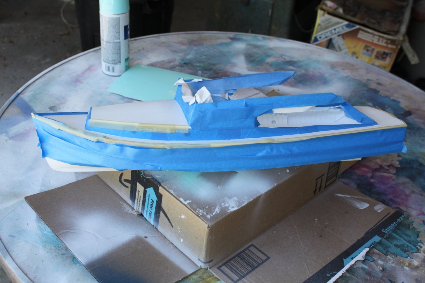
During my visit to the boat, the little I could see of the interior showed me that it was stained a deep reddish brown. I assume that it is probably the original color and finish from when the boat was built but I can't confirm it. I did my best to mix up some paint that would be close to a match and then painted the dash, side walls and underside of the roof. I also painted the transom the same color. Somewhere along the way aft, the paint changes to white. I could not tell exactly where so I just picked a spot that I liked. The directions only showed me two items to build for the interior. One was the helm and the other was the propane cabinet. It didn't show a companionway but I knew (as seen in the picture above) there had to be one. Having been in many different boats and based on what I could see, one was fabricated. The three pieces were painted, the wheel was added and they were installed. The engine box was also built and glued into place. I kind of wish that I had used some paper hole punch cut outs for gauges but I didn't think of it until after the roof was on......to late!! Another thing that was not mentioned in the directions was the grab rails. They were barely visible in the only picture of the completed model but not without the aid of a magnifying glass. My trip to the boat not only showed me where they were located but how they were made. I had actually built and installed them before I painted the interior. Once again, I used a sewing pin to drill pilot holes in the rails. More pins were cut off short and used to attach the rails to the cabin roof. I like the look of a large nail or carriage bolt that they give. The supplied port holes were painted with gold paint and gently pushed into place. Next came time to lay out and paint the waterline and bottom. As you can see, there are two colors used. One is a green boot stripe and the other is a reddish/burgundy color for the bottom. I mentioned before that I painted the transom the same color as the interior. I also said that I believe that the interior is the original finish. With that thinking in mind I figured that the transom must have been the same color as the interior when she was built. It seems unlikely to me that a second stain color would have been used, especially since there is also a stained cap around the cockpit as well. As an actual boat owner, (I'm sure a good many of us are) I know that this boat has had it's hull serviced and painted many many times over the coarse of it's seventy-two year life. Our 32' flybridge cruiser gets hers done every year. I also think that at some point in time when the transom was being re-done, someone picked a stain that was "close enough". After all, this is a "work boat". Most of the people who own and run these boats, be they charter boats or Skipjacks focus more on function rather than maintaining a pristine boat. But I could be wrong. Anyway, back to plotting the water line. This is always a tricky thing for me to do. I'm never really sure if I've gotten it right. First I put the boat on a nice flat level surface. Then it was blocked and leveled until It looked like it was in the right position. A block was cut and a pencil added. Then the line was drawn. A second line was drawn for the boot stripe before tapping off the hull and painting it green. That's all for now folks.


- 20 replies
-
- 6
-
-
- Breezin Thru
- Wye River Models
- (and 1 more)
-
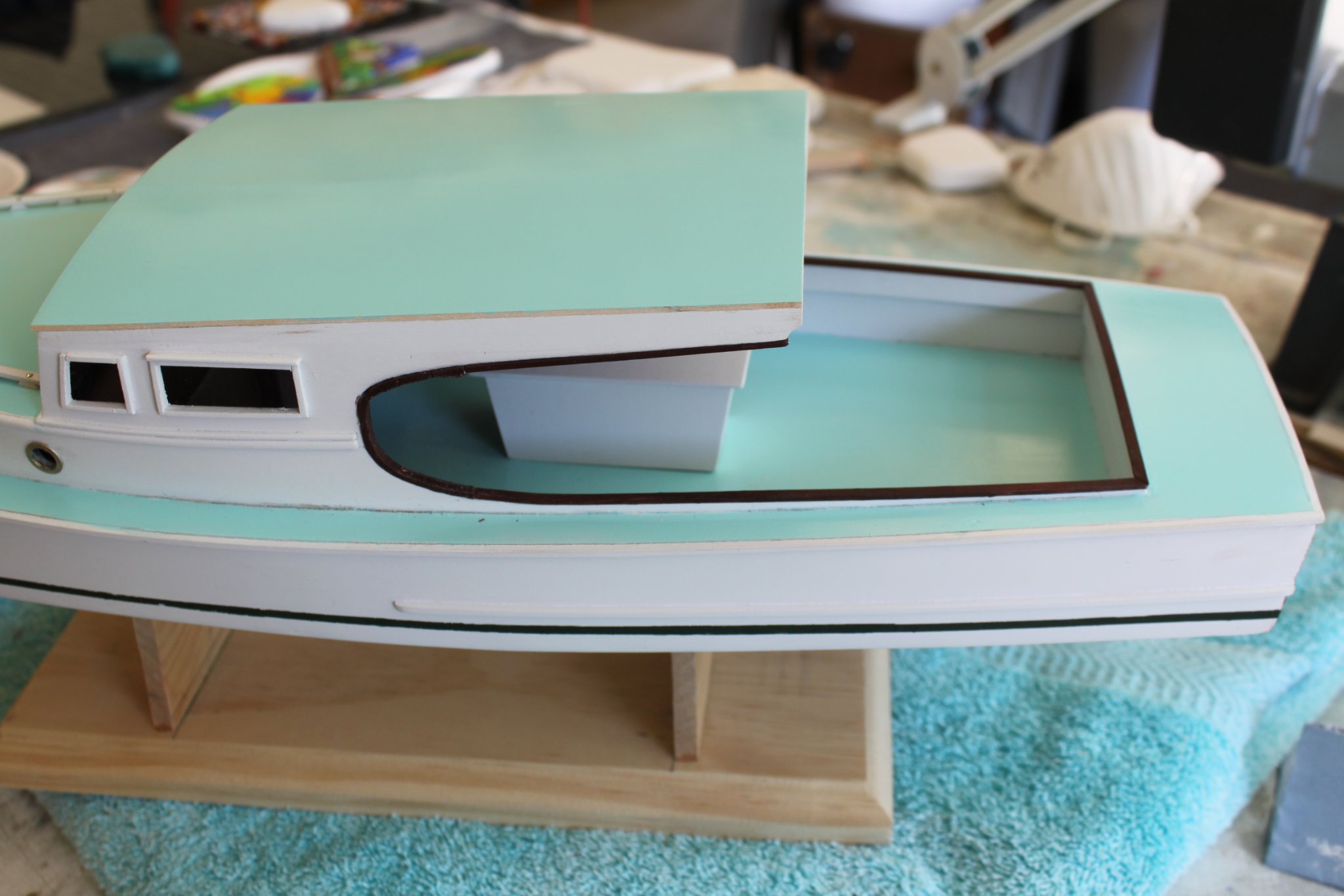
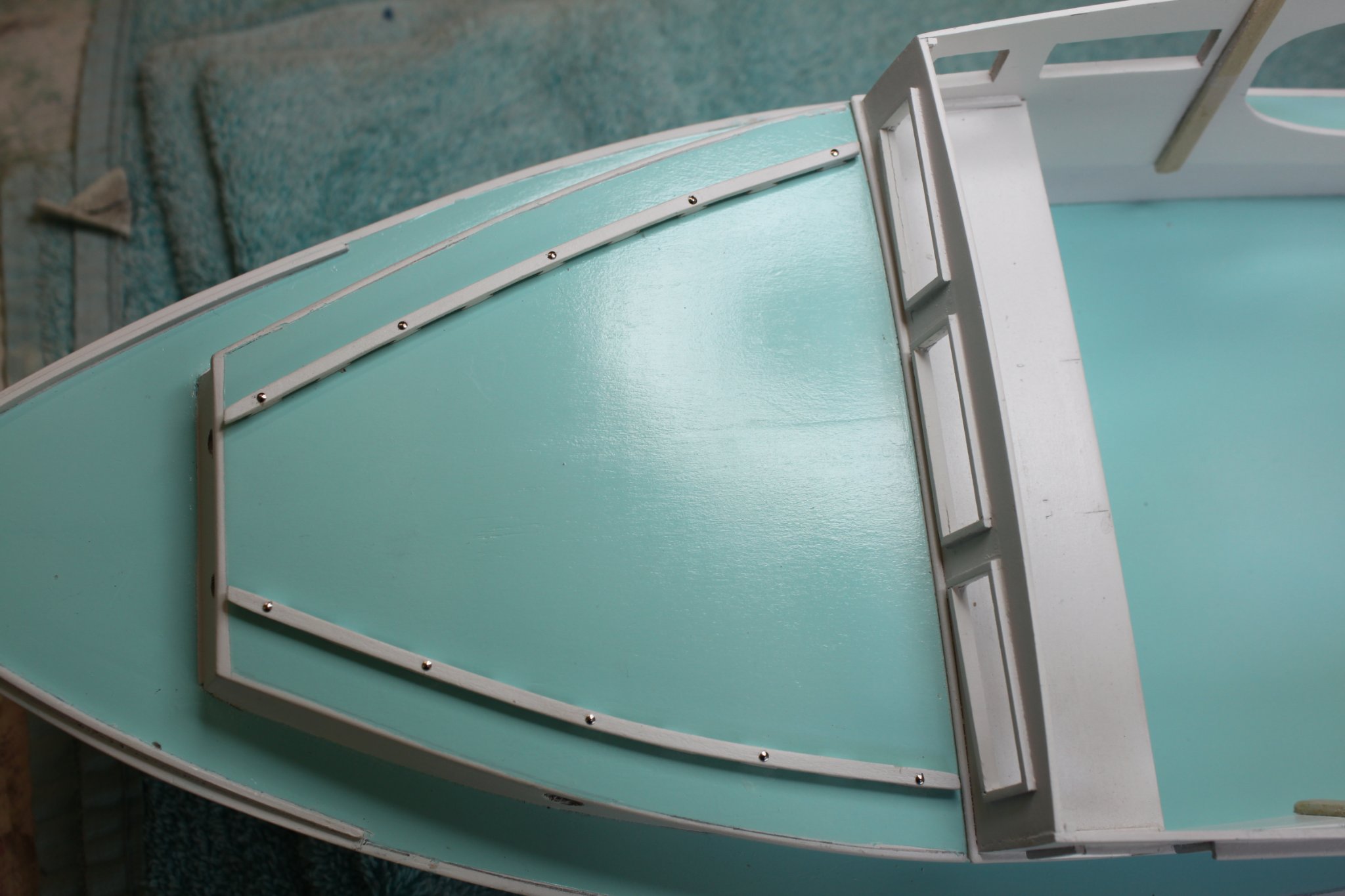
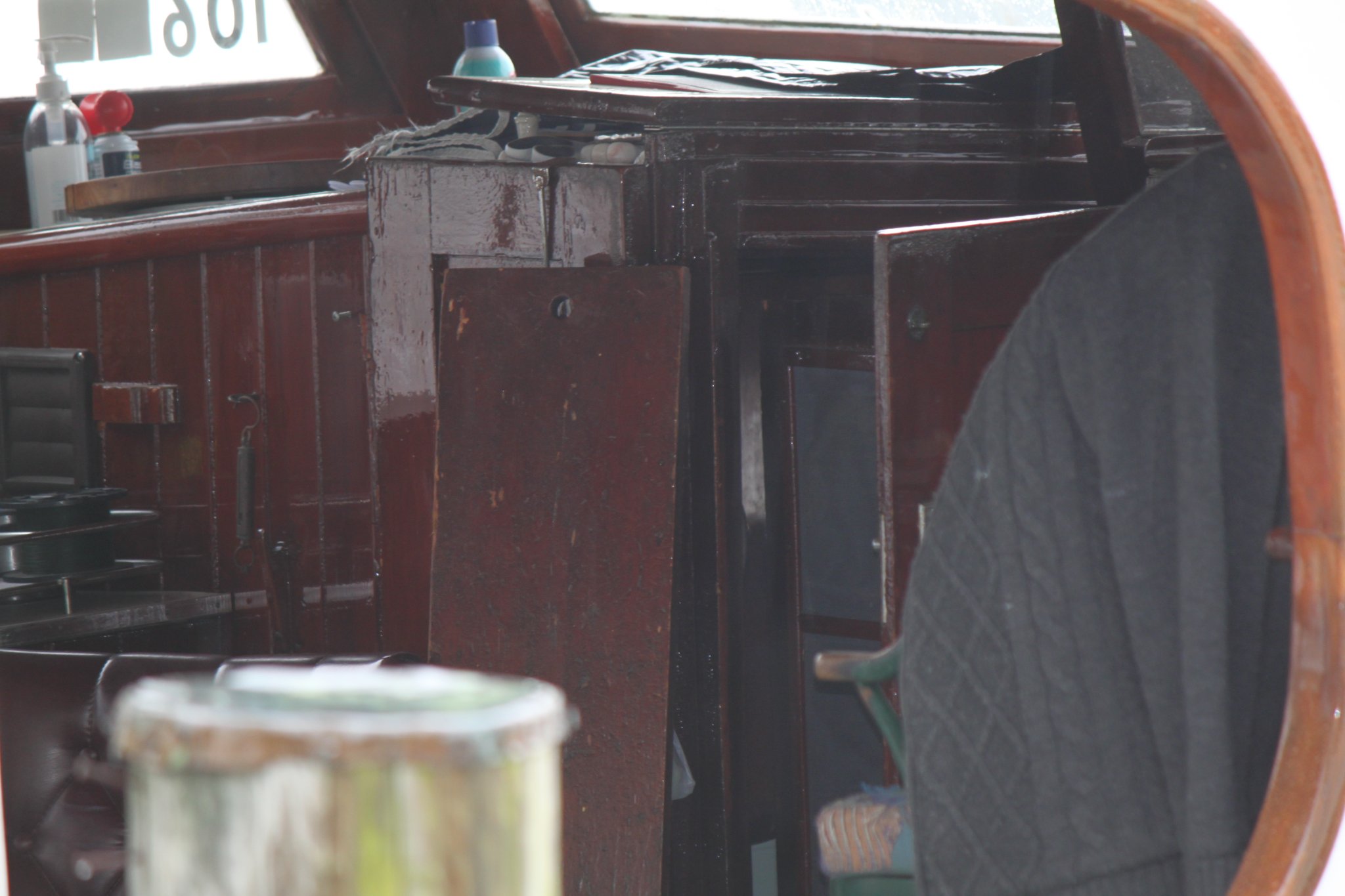
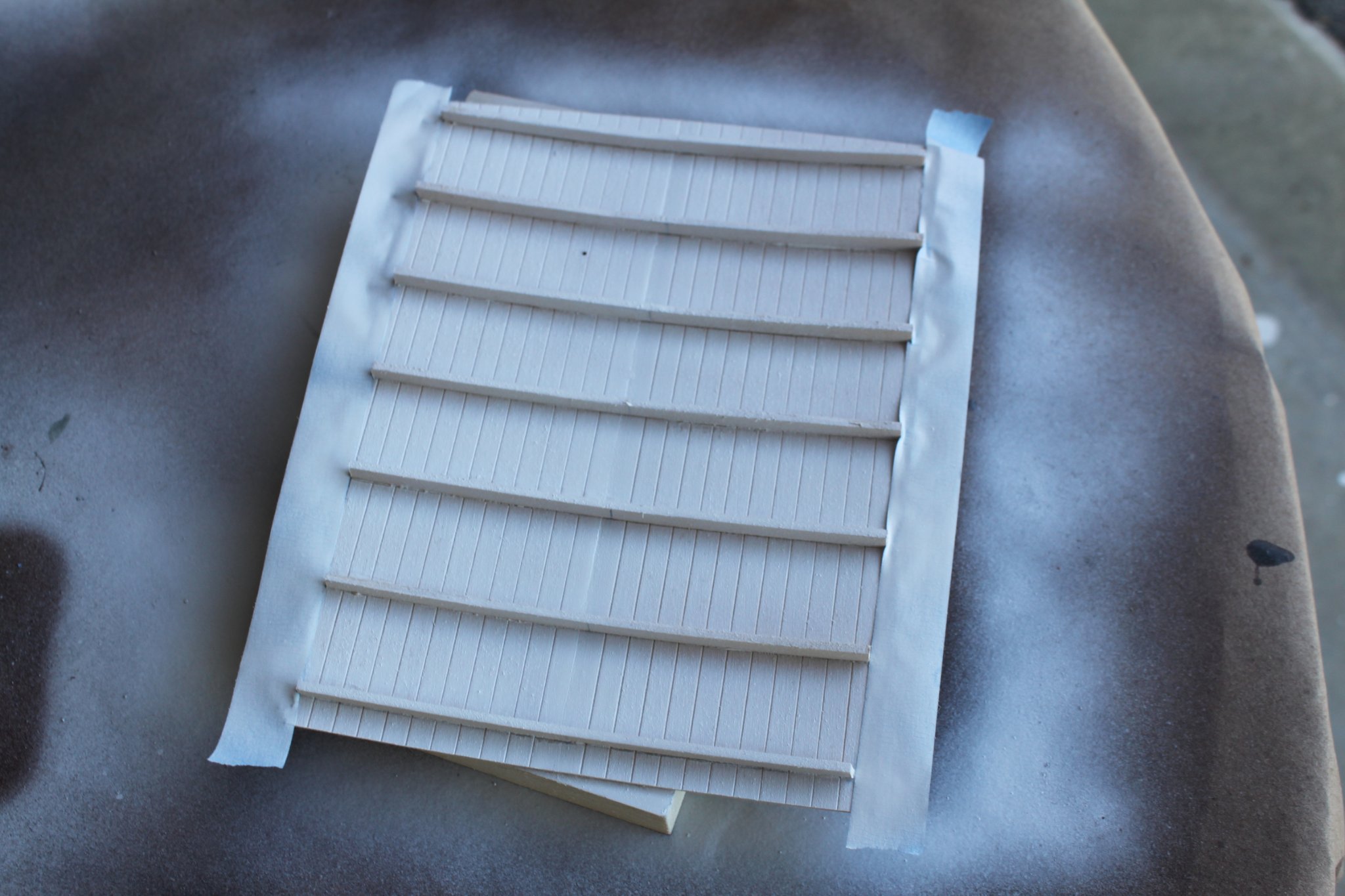
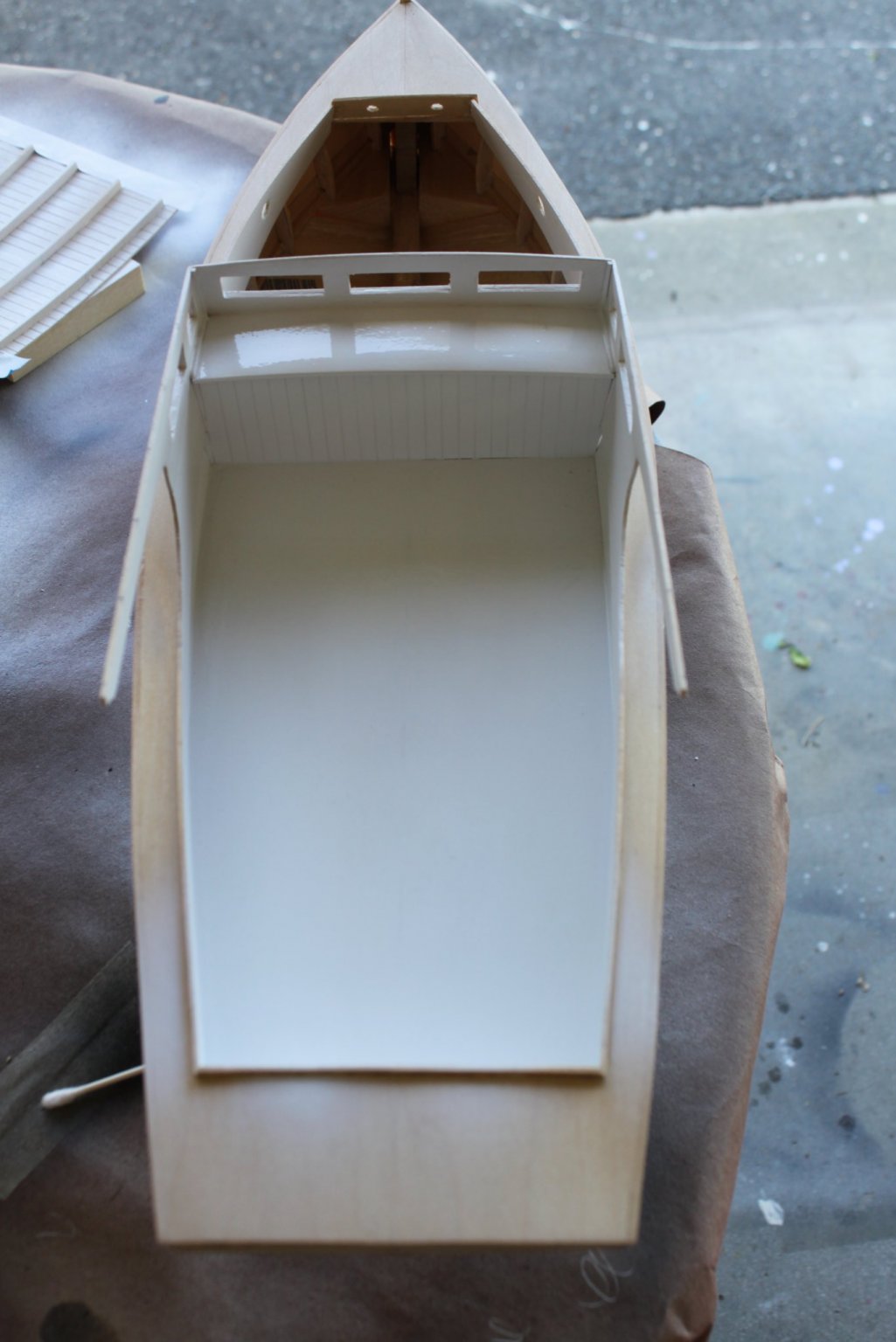
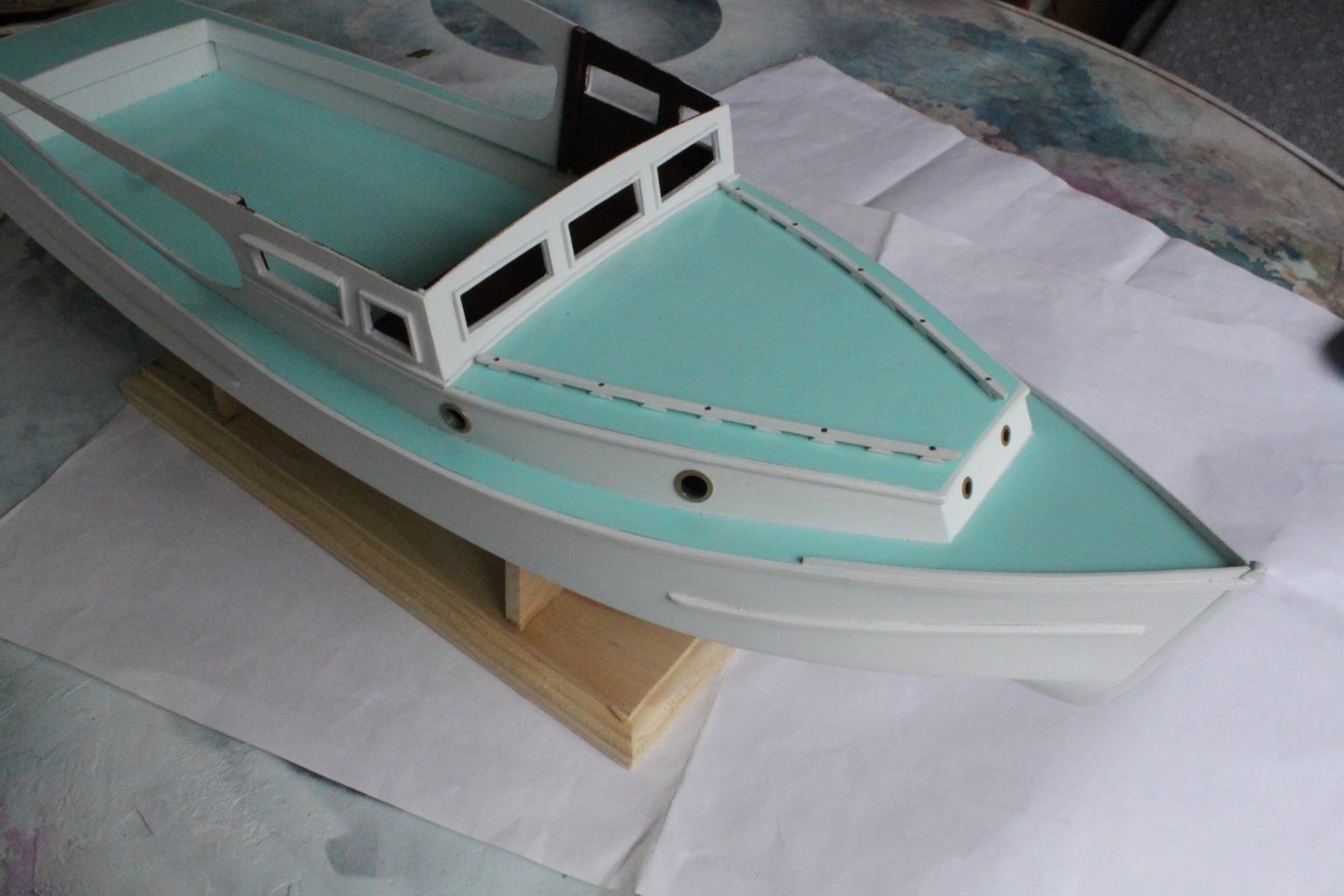
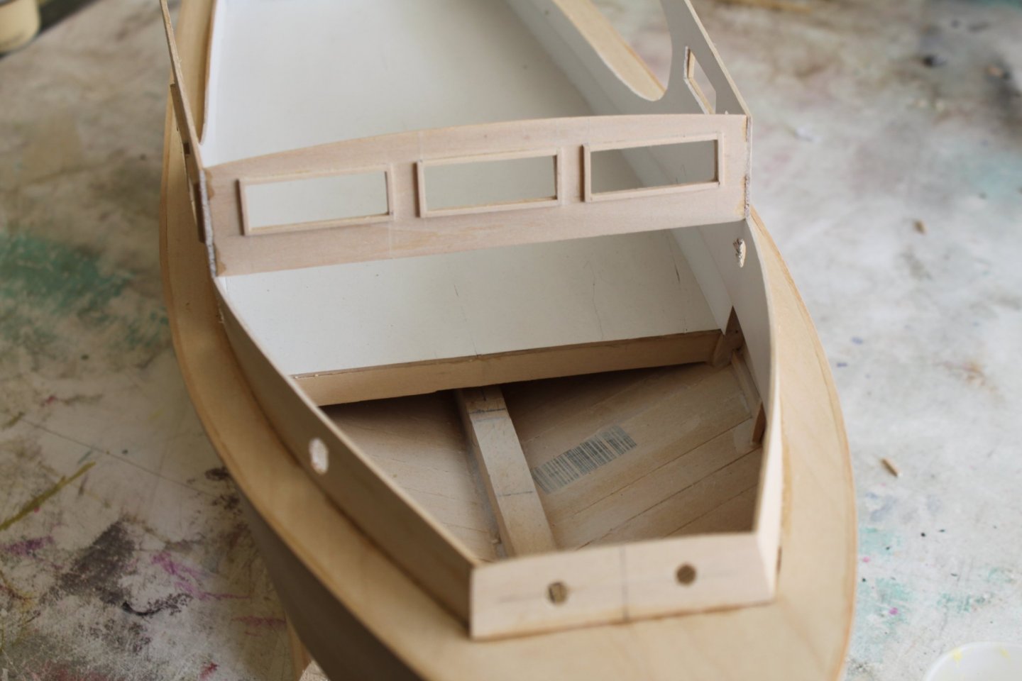
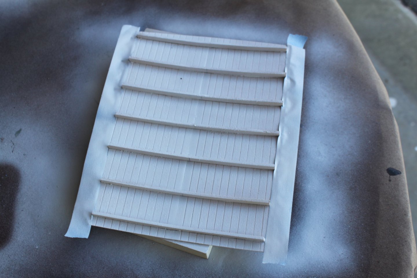
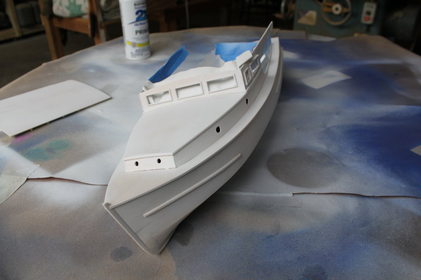
The next step was to make the pilot house and cabin sides. I was able to use the template that was supplied. It just needed to be shortened by about a half inch. Obviously, drilling the holes for the port lights and cutting the windows were done before installing the sides. After tacking it in place in several places, the front windshield was cut and fit. I also framed out the windows. From there I started working on the two sections of roofing. The pilot house roof was cut to length and a gentle curve cut along the front. The upper sides of the pilot house walls were temporarily held in place so that measurements could be taken. Then arched beams were cut to length based on the center line and glued to the underside of the roof. The roof was left wide so that it could be trimmed flush to the sides after gluing. Sorry, I didn't take any pictures of the cabin roof but it was produced in the same manner. In this picture you see the pilot house roof glued up and primed. The cabin roof was installed but not the pilot house roof. There are a number of things that need to be built and some painting that will need to be done before it can be attached. Here is a picture of the dash and cabin bulkhead installed just before the cabin roof was. The inside was primed as well. This is the point where the lack of details in the instruction booklet started to become an even bigger problem. Although I won't be including every minuet detail down to dents and scratches, I do need enough of them to be able to distinguish this boat from the hundreds/thousands of similarly styled charter boats. One of the benefits to building models of boats that still exist is that you can (potentially) go see them. As jhearl (John) pointed out, Breezin' Thru is located at Kentmoor Marina on Kent Island. It's about and hour and fifteen minute drive from my house so I went to see her. Unfortunately it was a rainy day just a few weeks before the start of trophy season and no one was at the boat. To further complicate matters, she was buttoned up tight. However, I was able to get enough pictures of her to aid me in adding the details I needed. In the next picture you will see that the cabin roof has been installed. A Bullnose (half round) drip edge was also added. I wouldn't have known that it was a bullnose had I not visited the boat. A smaller half round trim was also added under the front and side windows as well as some hull details. This is the point I primed the rest of the exterior. Once again my trip to see the actual boat paid off. While there, I learned that there are five different colors on the boat. Obviously an important thing to know. The main deck/wash boards, both roofs and the cockpit deck are all a light turquoise/blueish color. To my surprise, we had a can of spray that is very close in color. The areas of the hull that were to remain white were taped off and painted along with the pilot house roof. From here more work and painting will need to be done to the inside before the roof is attached. That's coming up in the next post.


- 20 replies
-
- 4
-
-
- Breezin Thru
- Wye River Models
- (and 1 more)
-
Very nice looking model!! WOW, it's even got an active windless, cool. I will have a look and see if I can find some of that wire. I was just going to paint the edge but wire would definitely be better. Thanks for the info. Reed
- 20 replies
-
- 2
-
-
- Breezin Thru
- Wye River Models
- (and 1 more)
-
Shore thing reacted to a post in a topic:
Breezin Thru by Shore thing - FINISHED - Wye River Models - 1/2" scale
-
Shore thing reacted to a post in a topic:
Breezin Thru by Shore thing - FINISHED - Wye River Models - 1/2" scale
-
Great picture of the Breezin' Thru John. Yes, she's still there. I was waiting until later in the thread to comment on the fact that I am able to actually see the boat in person. I took a trip there a couple months ago because I needed to see some of the details that the directions don't mention. Unfortunately it was a rainy day and she was buttoned up tight. It was also a few weeks before fishing season was open so no one was there either.
- 20 replies
-
- 1
-
-
- Breezin Thru
- Wye River Models
- (and 1 more)
-
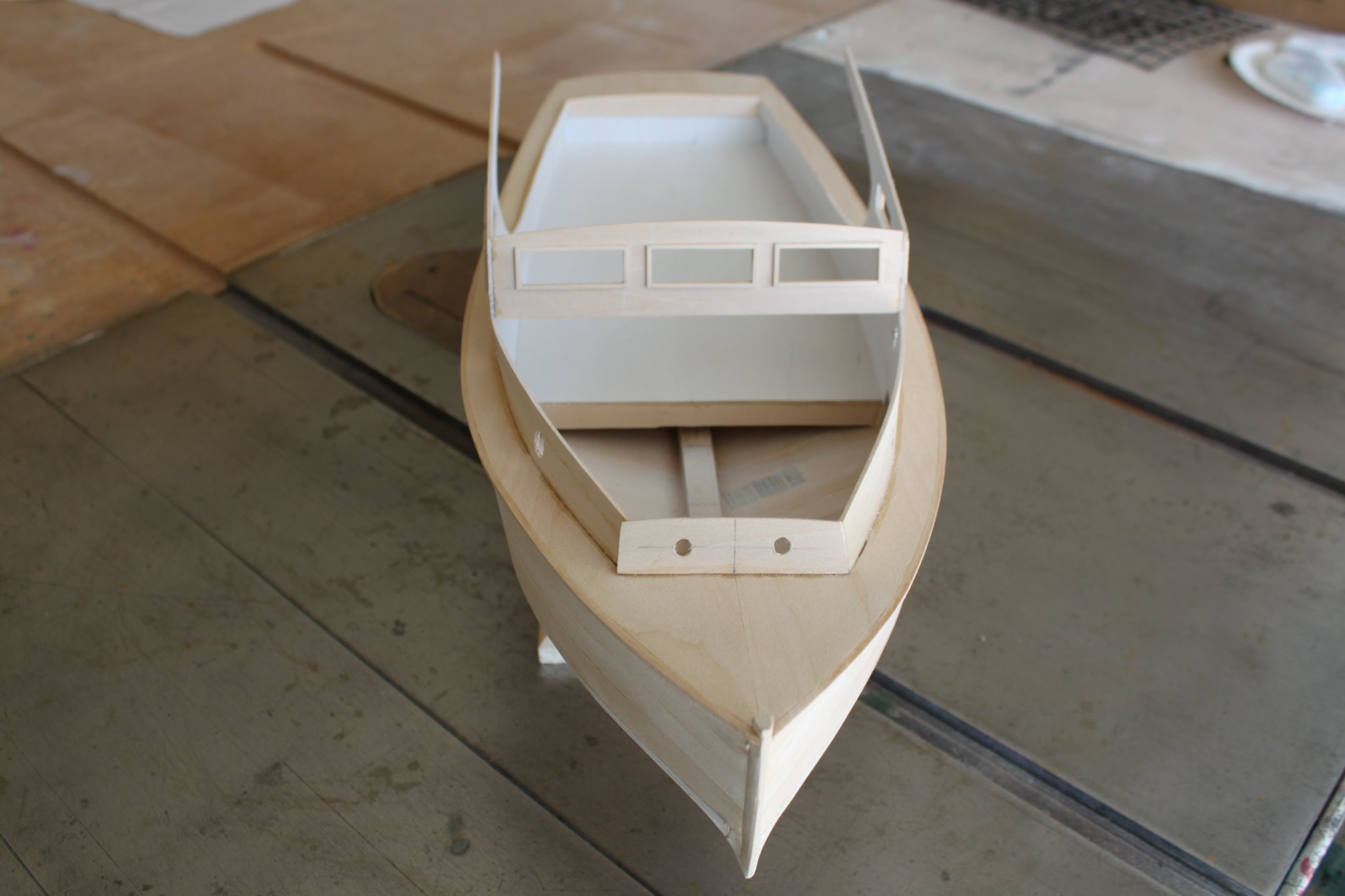
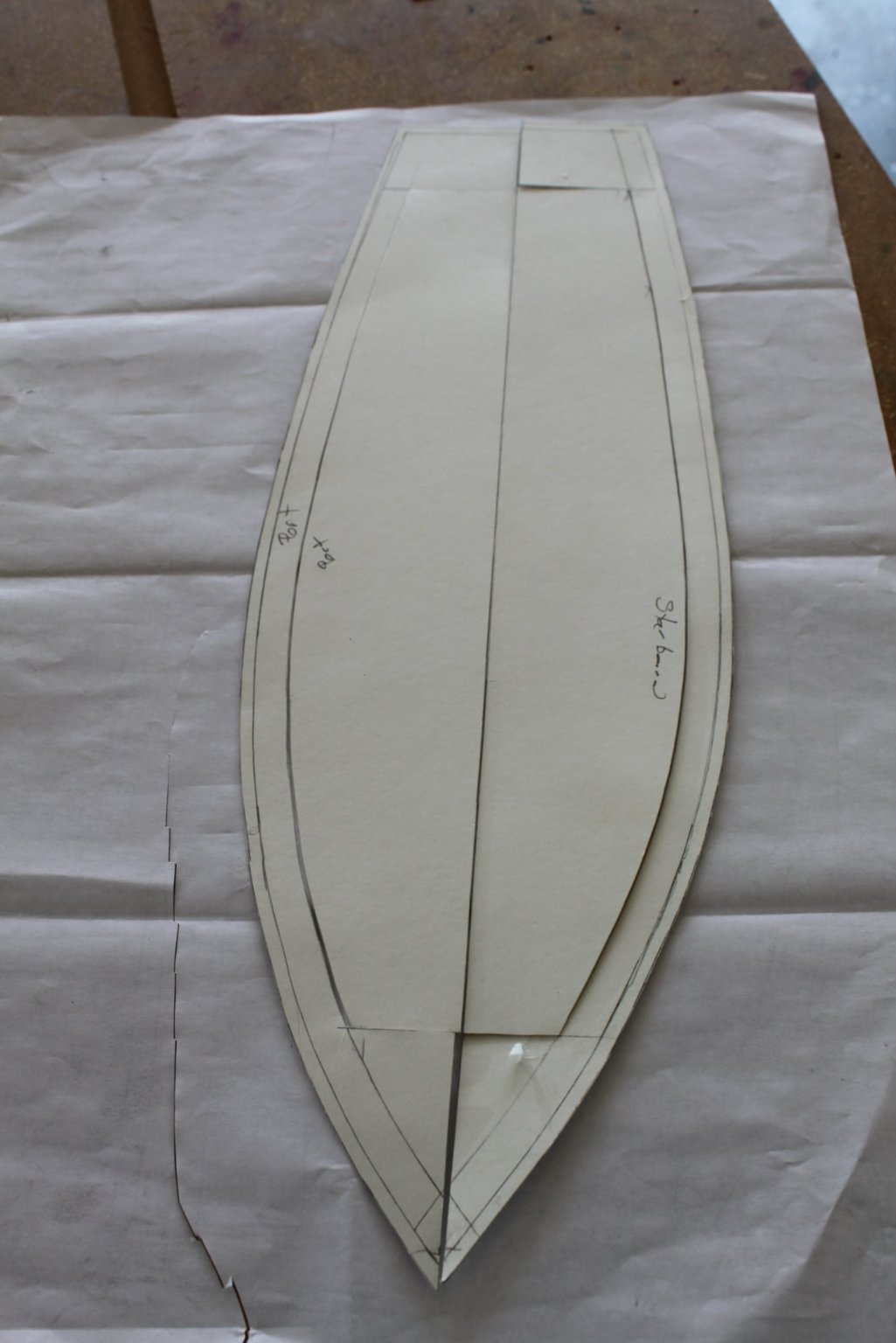
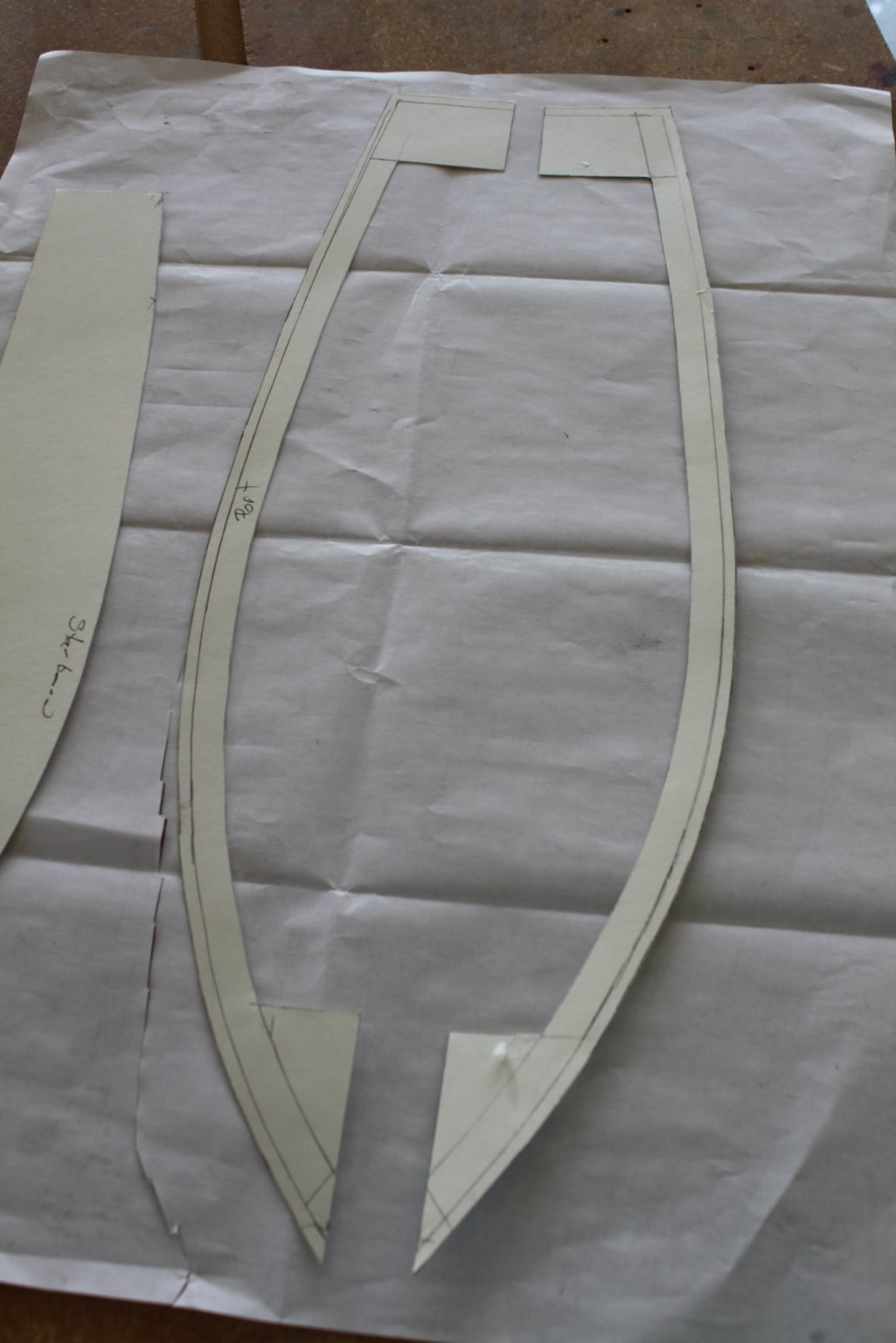
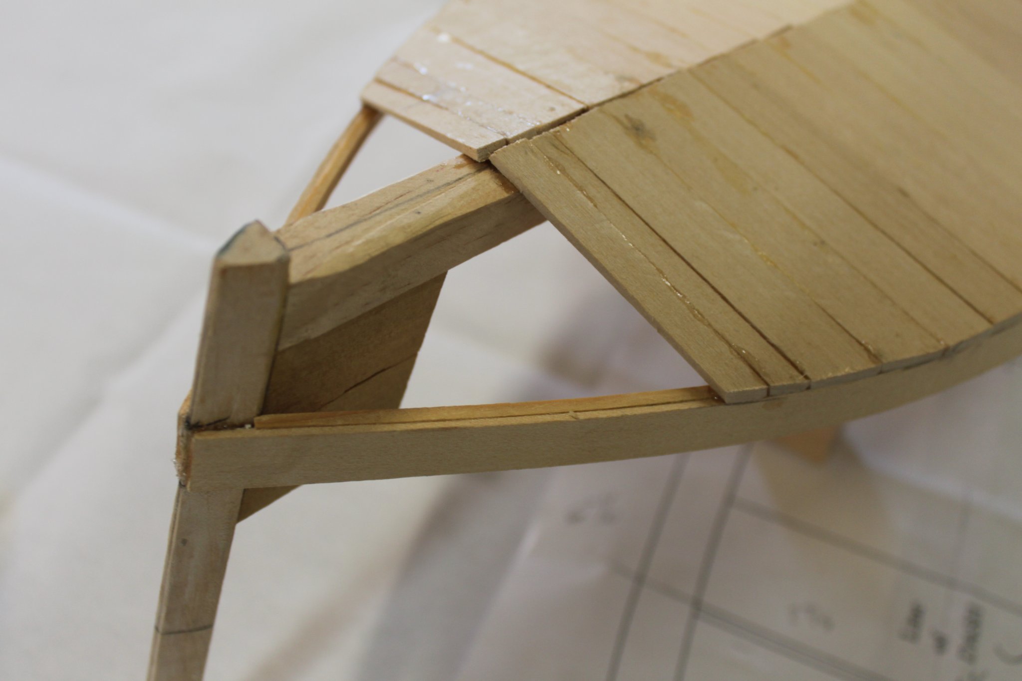
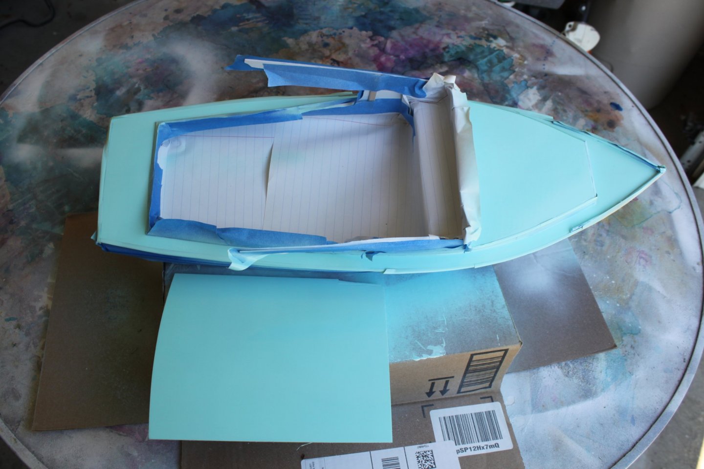
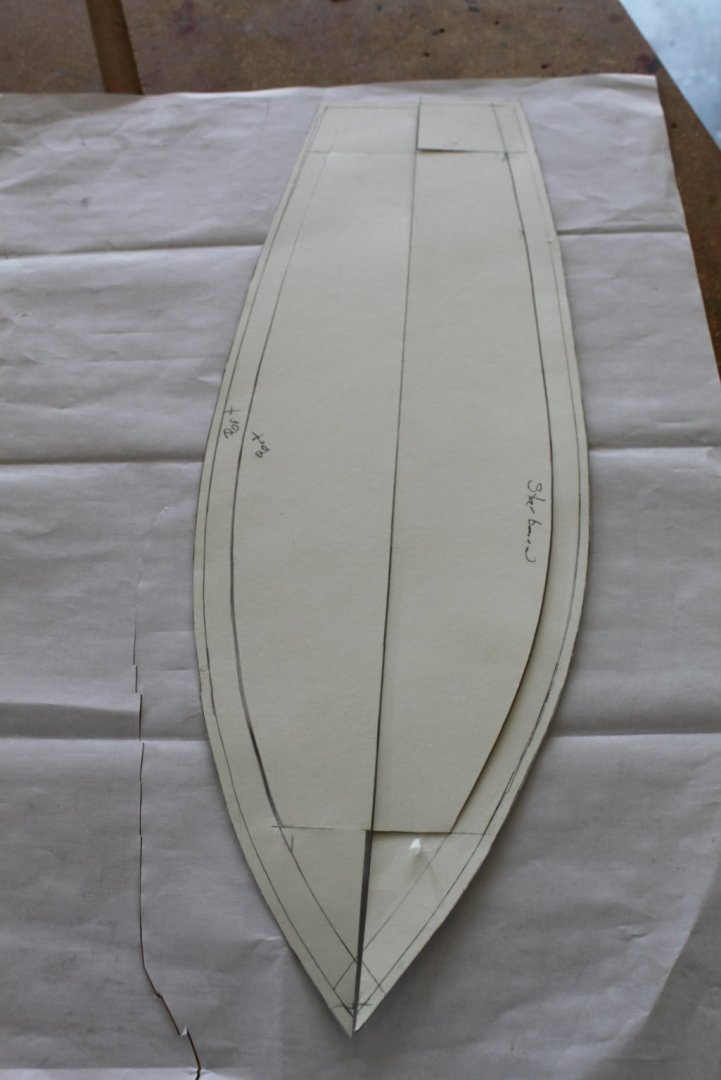
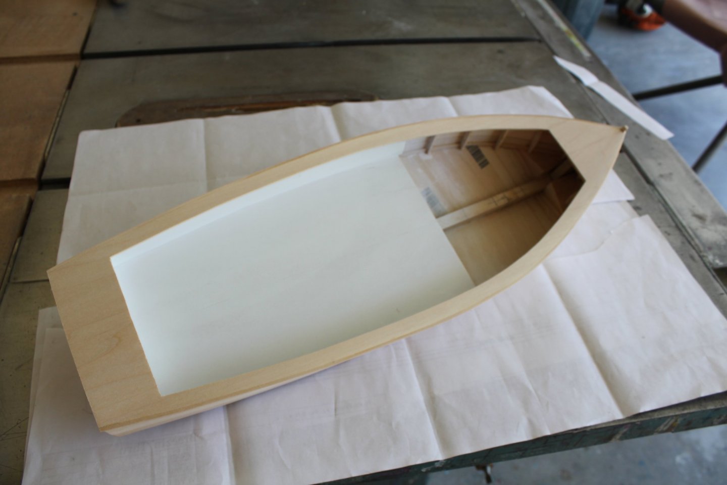
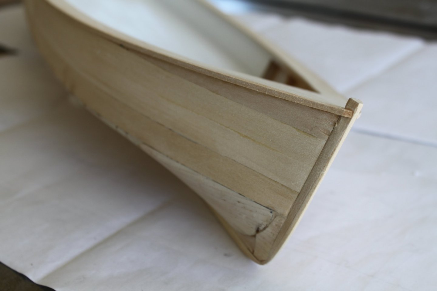
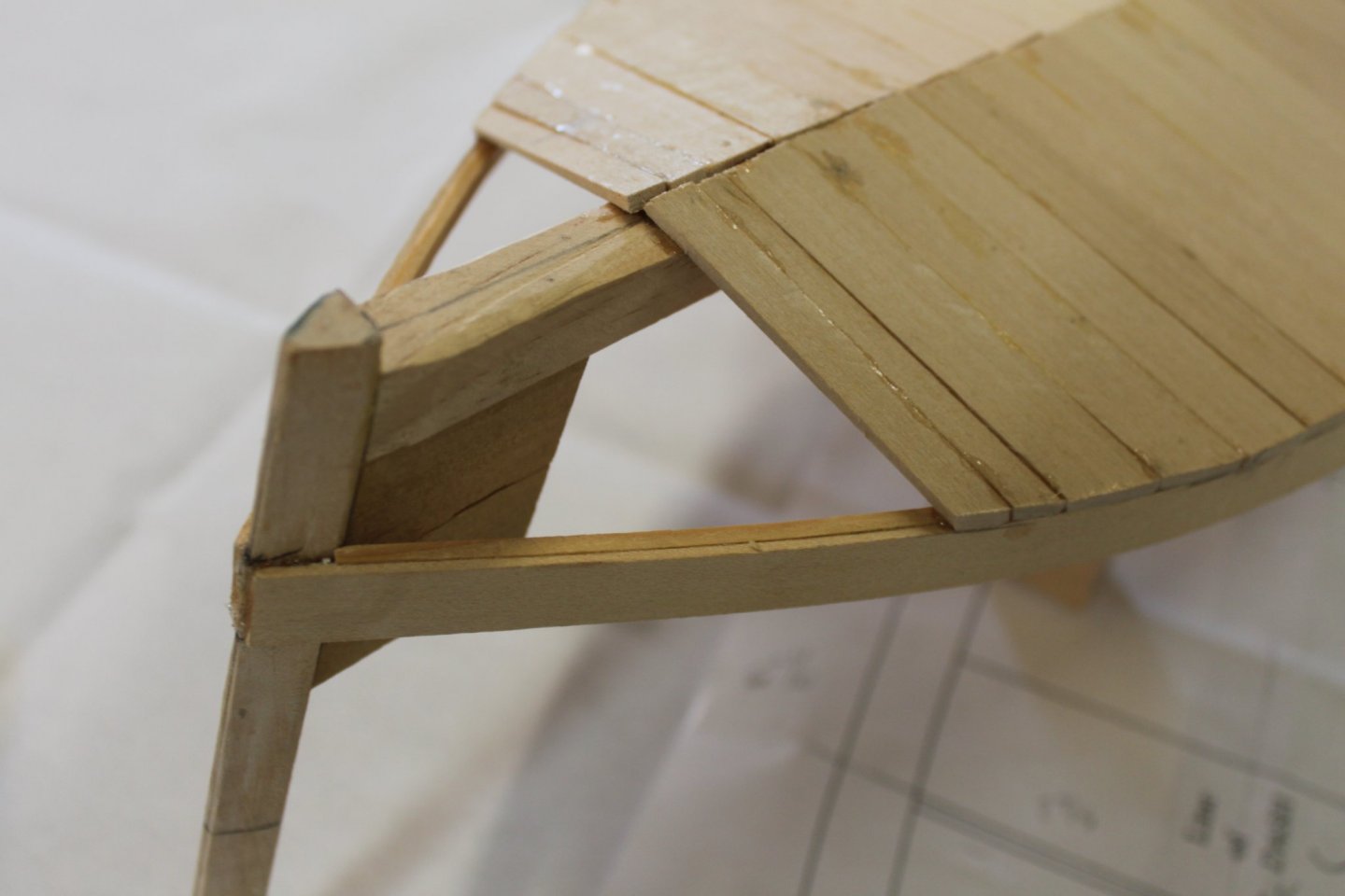
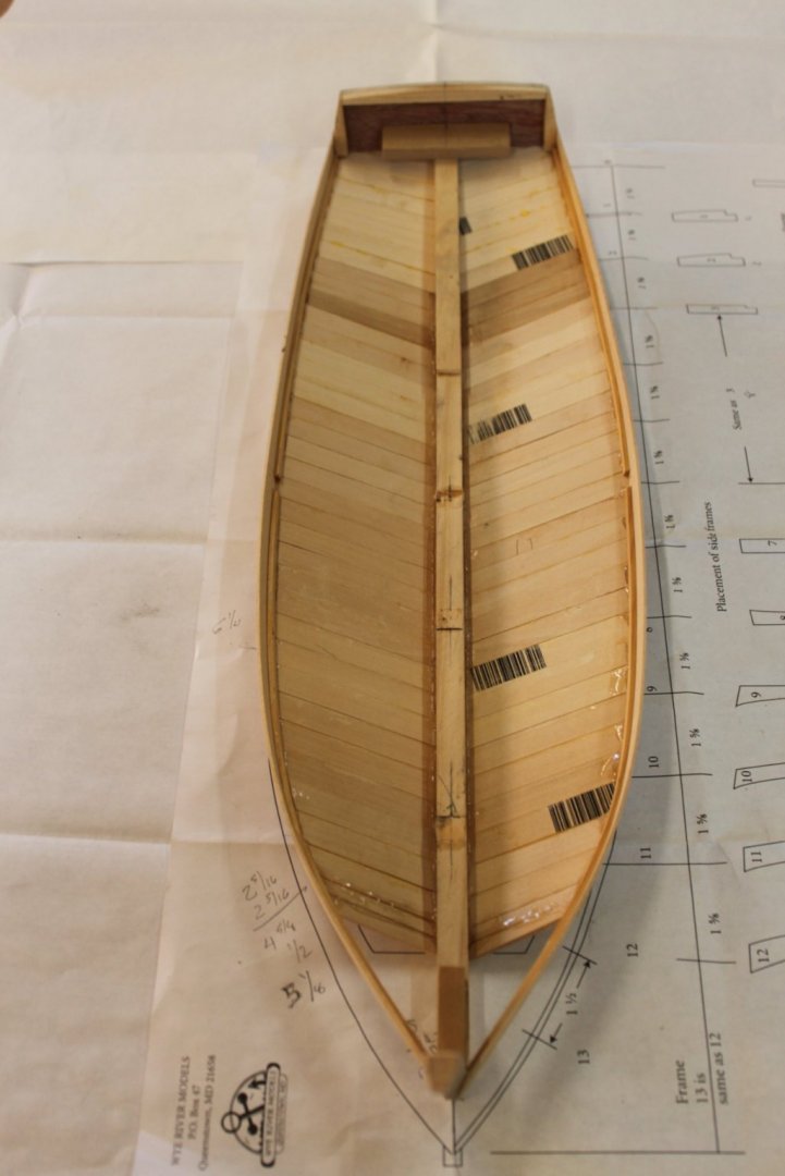
At this point I added the stem to the hull and then continued fairing the chunk along with the stem into the hull. Since my hull did not turn out exactly like the template that was provided with the plans, the template for the deck was mostly useless to me. However, it did give me a few basic measurements to go by. I flipped the model over and traced the shape on to construction paper. It's a little hard to see but this picture also shows the overhang of the rub rails. From there I plotted out the details in relation to my hull. Then the templates were cut out, fine-tuned and traced on to the sheets of decking material. While working on the deck/wash board patterns I was also working on the cockpit decking. It would need to be installed before the hull decking/wash boards. A number of deck beams for the cockpit decking were installed by gluing them to the frames. The two pieces of cockpit decking were fit to the inside of each side of the hull and then glued together. After sanding they were primed and installed. A beam was also cut to support the wide section of the deck/wash boards near the transom. Finally it was time for the deck/wash boards to be added. After the glue dried and some light sanding, side and transom panels were fit. A piece of 1/8" x 1/8" stock was glued to each side for rub rails. Here's a picture of the bow section with the stem and chunk faired in to the hull.

- 20 replies
-
- 3
-
-
- Breezin Thru
- Wye River Models
- (and 1 more)
-
Shore thing reacted to a post in a topic:
Chesapeake Bay Skipjack by Dsmith20639 - FINISHED - Horizon - 1/32
-
Shore thing reacted to a post in a topic:
Chesapeake Bay Skipjack by Dsmith20639 - FINISHED - Horizon - 1/32
-
Shore thing reacted to a post in a topic:
Breezin Thru by Shore thing - FINISHED - Wye River Models - 1/2" scale
-
Shore thing reacted to a post in a topic:
Breezin Thru by Shore thing - FINISHED - Wye River Models - 1/2" scale
-
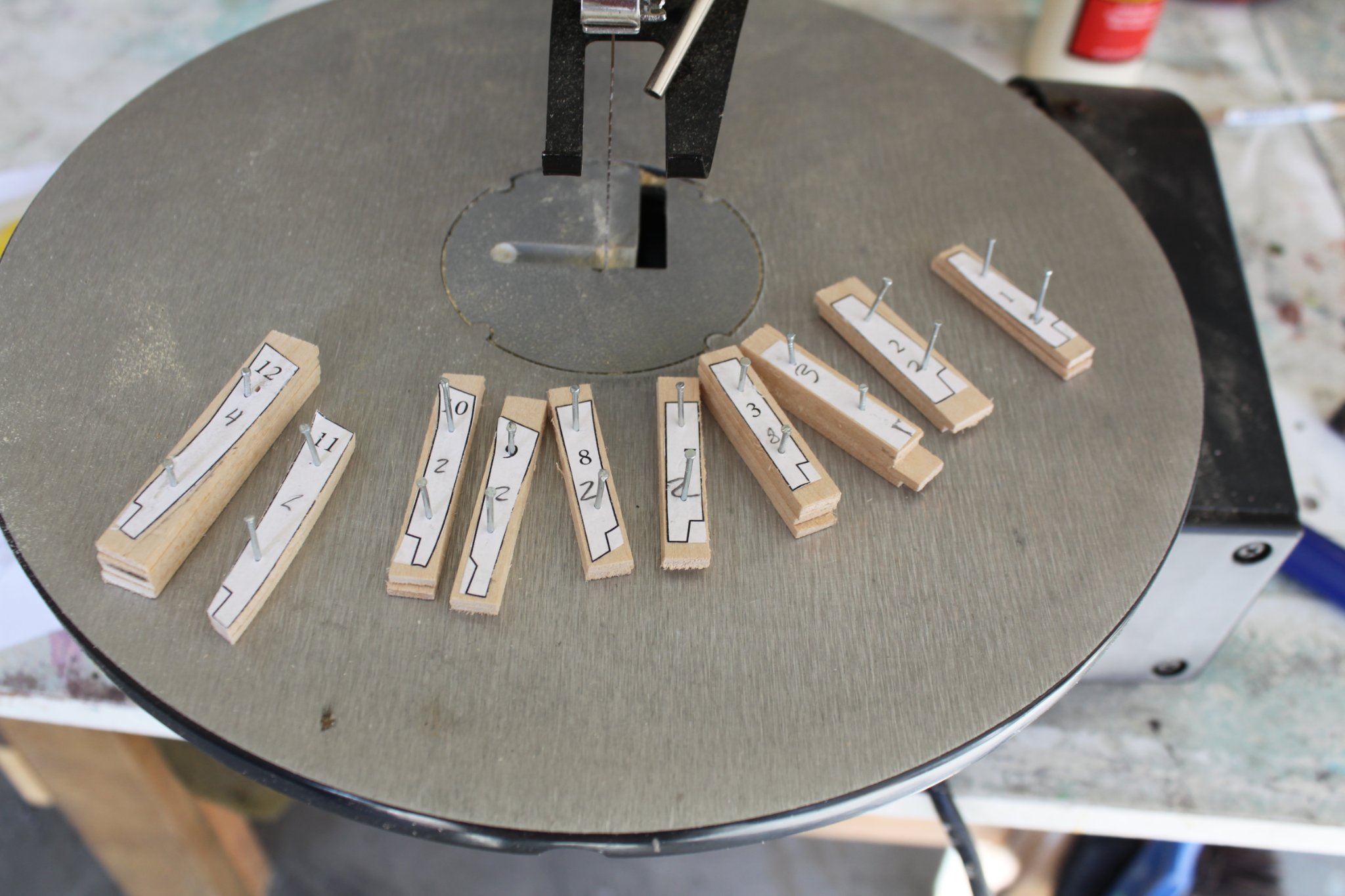
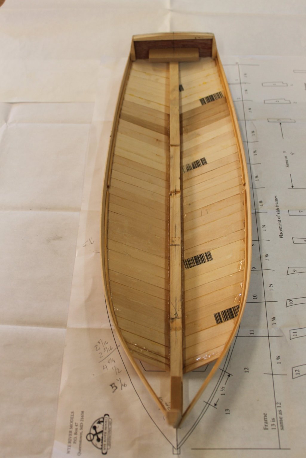
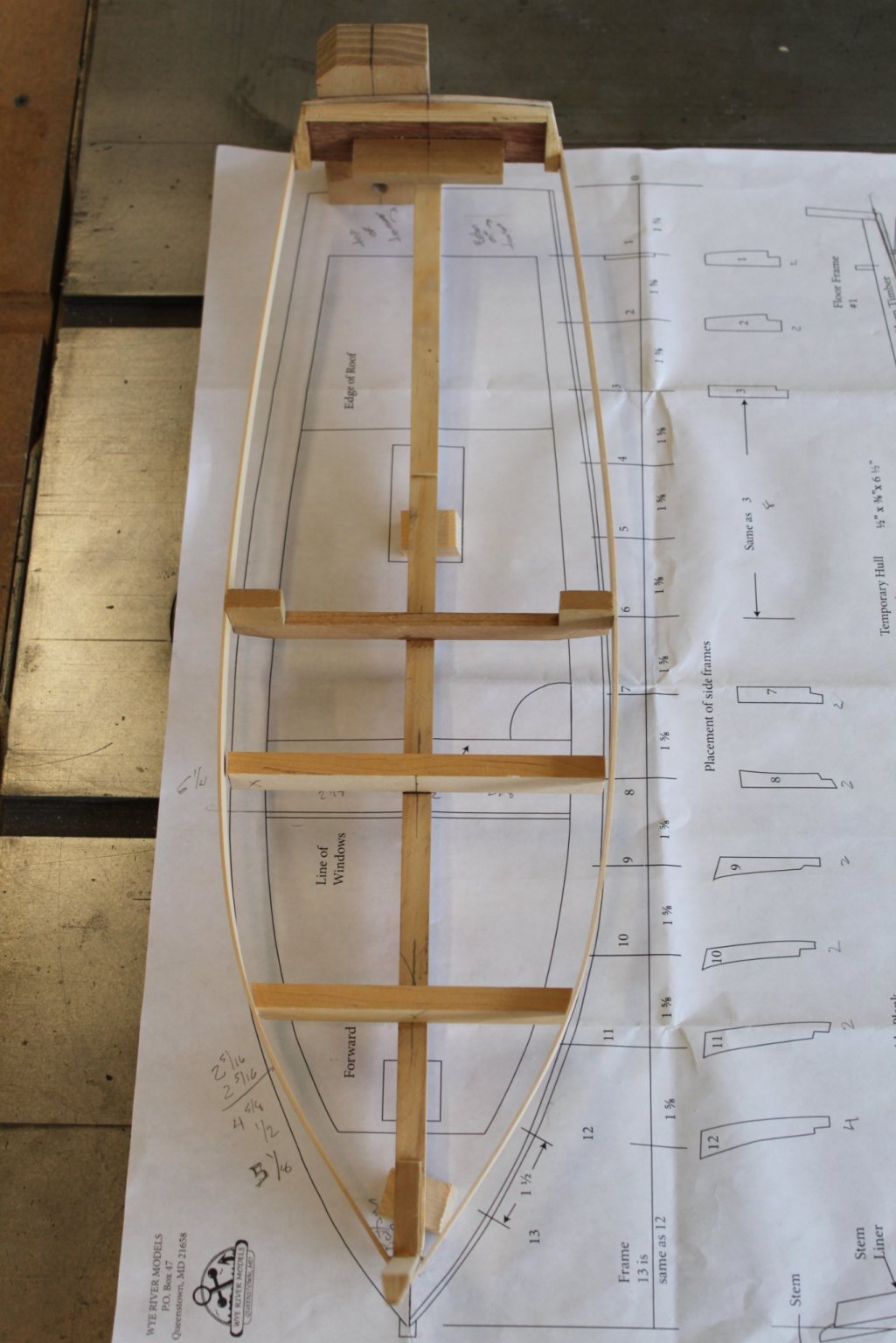
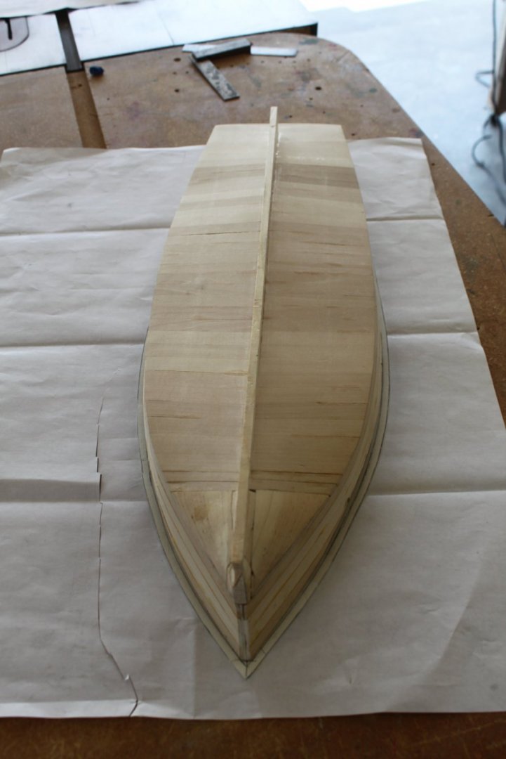
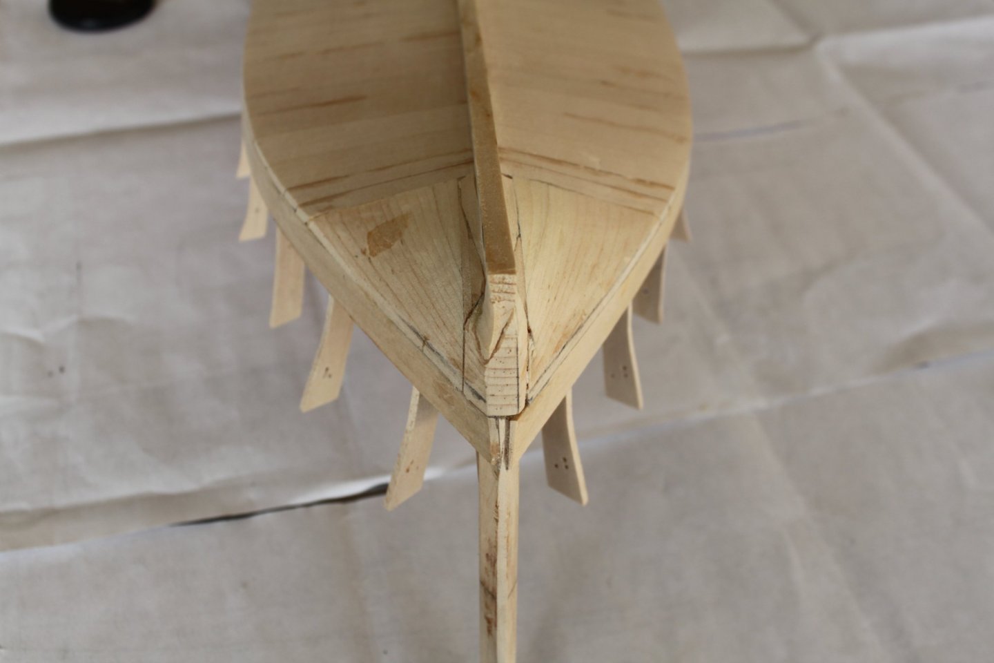
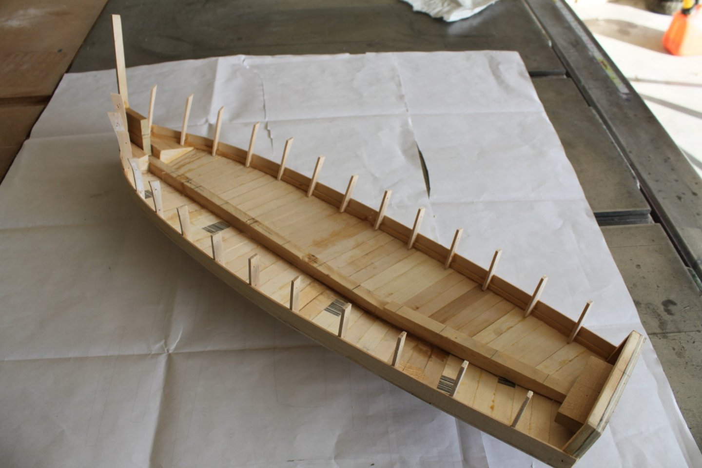
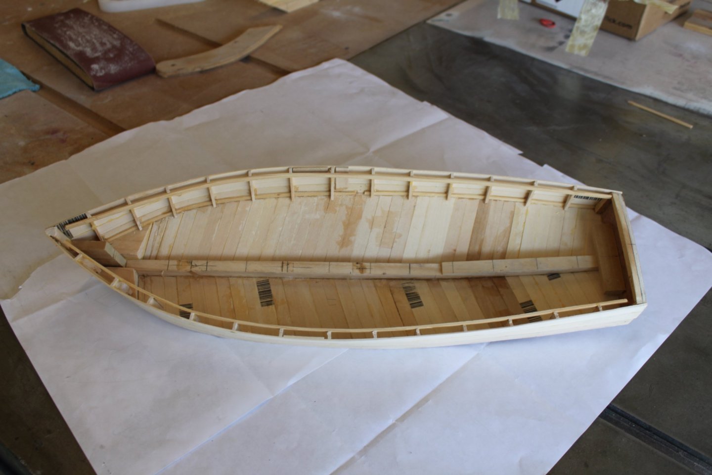
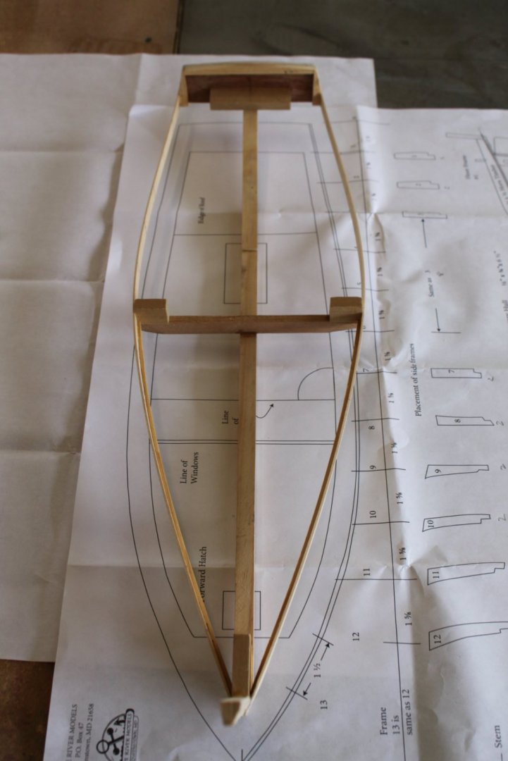
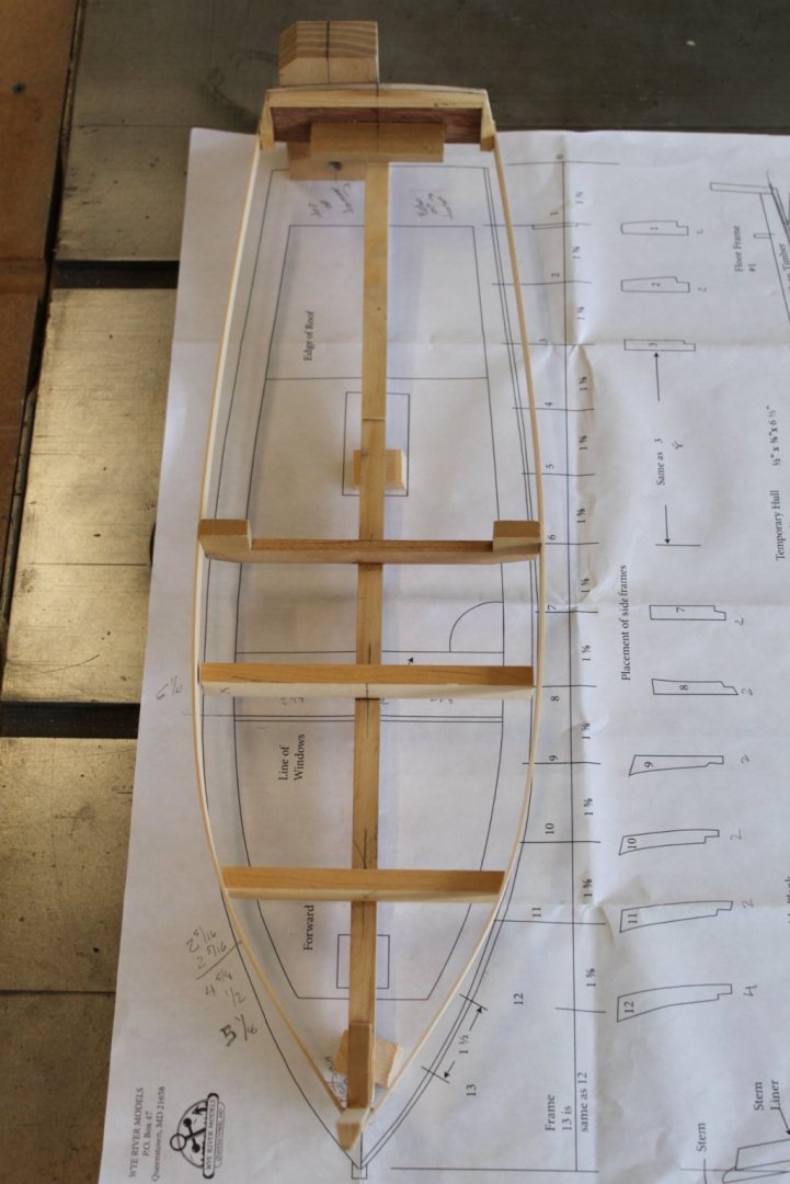
Opps, I got a little ahead of myself. After planking the bottom to the point shown in the last photo, I needed to add the "chunk" of solid wood to the bow section. A chunk is used because the planking will no longed bend and twist enough to form the bow. Once again there was no mention or pictures of the chunk in the instruction booklet. Unfortunately, I forgot to take pictures of the chunk before it was carved into it's rough shape. Here's a picture of the area that will require the chunk, This picture shows the chunk with the keel added and then roughly carved into shape. As you can see, the frames/ribs have been installed as well. I will show that process in the next few pictures. Here are the frame templates that were glued to the frame stock before cutting. I tacked two or more pieces together so that I would have matching frames for both sides of the hull. Notice the area where a notch is to be cut at the bottom of the frames. That is another indication that a chine log was meant to be added. The frames cut, sanded and glued in place. You can also see a view of the chunk on the inside of the hull. The hull planking was then bent and glued around the frames. It took three full length pieces of 1/16" x 1/2" wood to plank the majority of the hull. A fourth piece needed to be tapered from the bow to a point at approximately amidships. Once the planking had dried, the tops of the frames were trimmed and sanded where needed. An additional strip of wood was then glued flush to the top of the frames. It adds strength to the hull and also provides a "shelf" for the deck to be glued to. The the hull is now ready for the deck.

- 20 replies
-
- 6
-
-
- Breezin Thru
- Wye River Models
- (and 1 more)
-
Shore thing reacted to a post in a topic:
Breezin Thru by Shore thing - FINISHED - Wye River Models - 1/2" scale
-
Michael, thank you for your interest. You are correct, there is only the one row of side planking at this time. It was necessary to plank the bottom before adding more side planking so that the hull would would have enough structural integrity to hold it's shape. The next step will be to add frames/ribs to the inside of the hull. They will help to further define the shape of the hull and provide gluing surfaces for the side planking.
- 20 replies
-
- 2
-
-
- Breezin Thru
- Wye River Models
- (and 1 more)
-
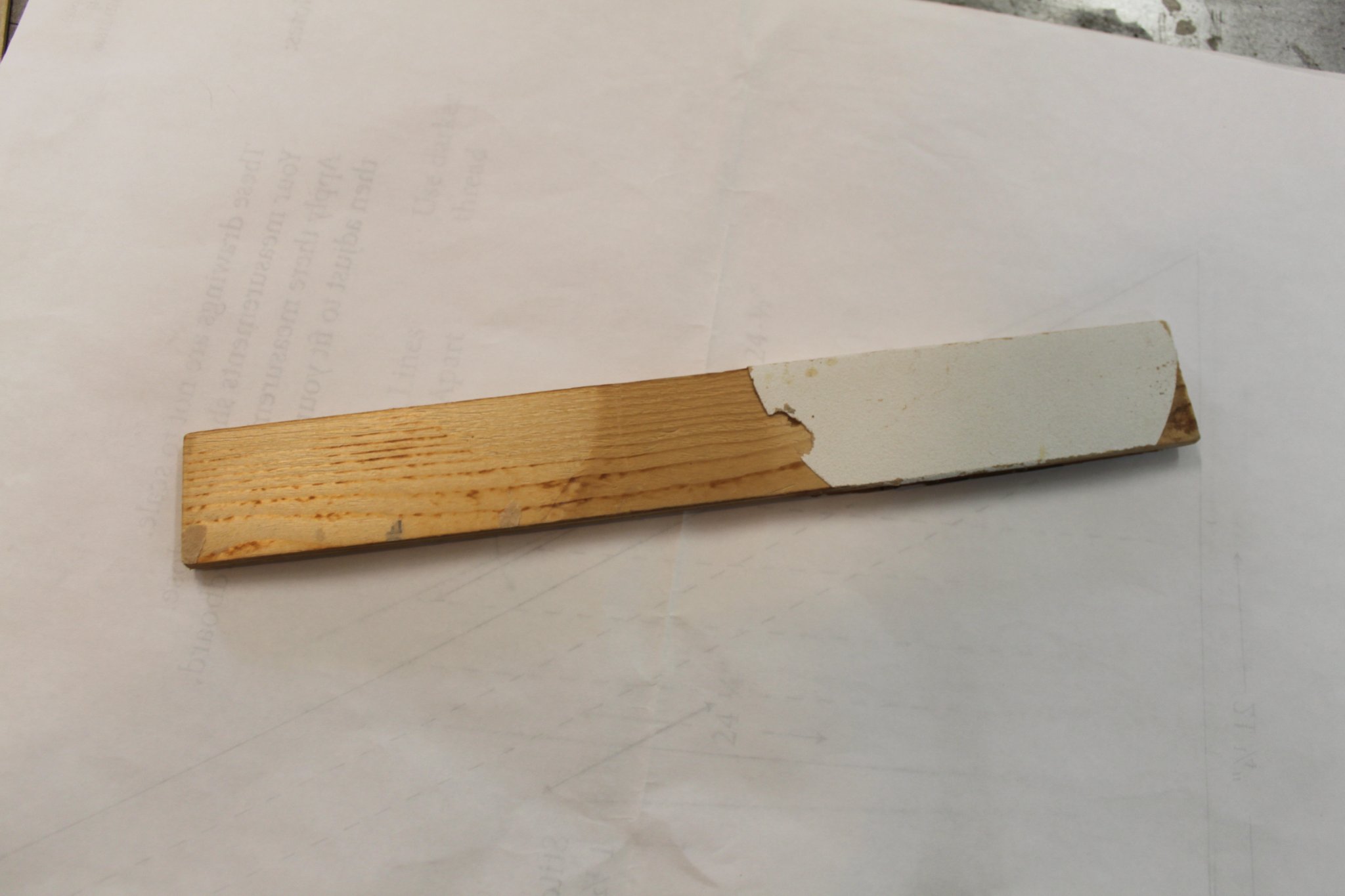
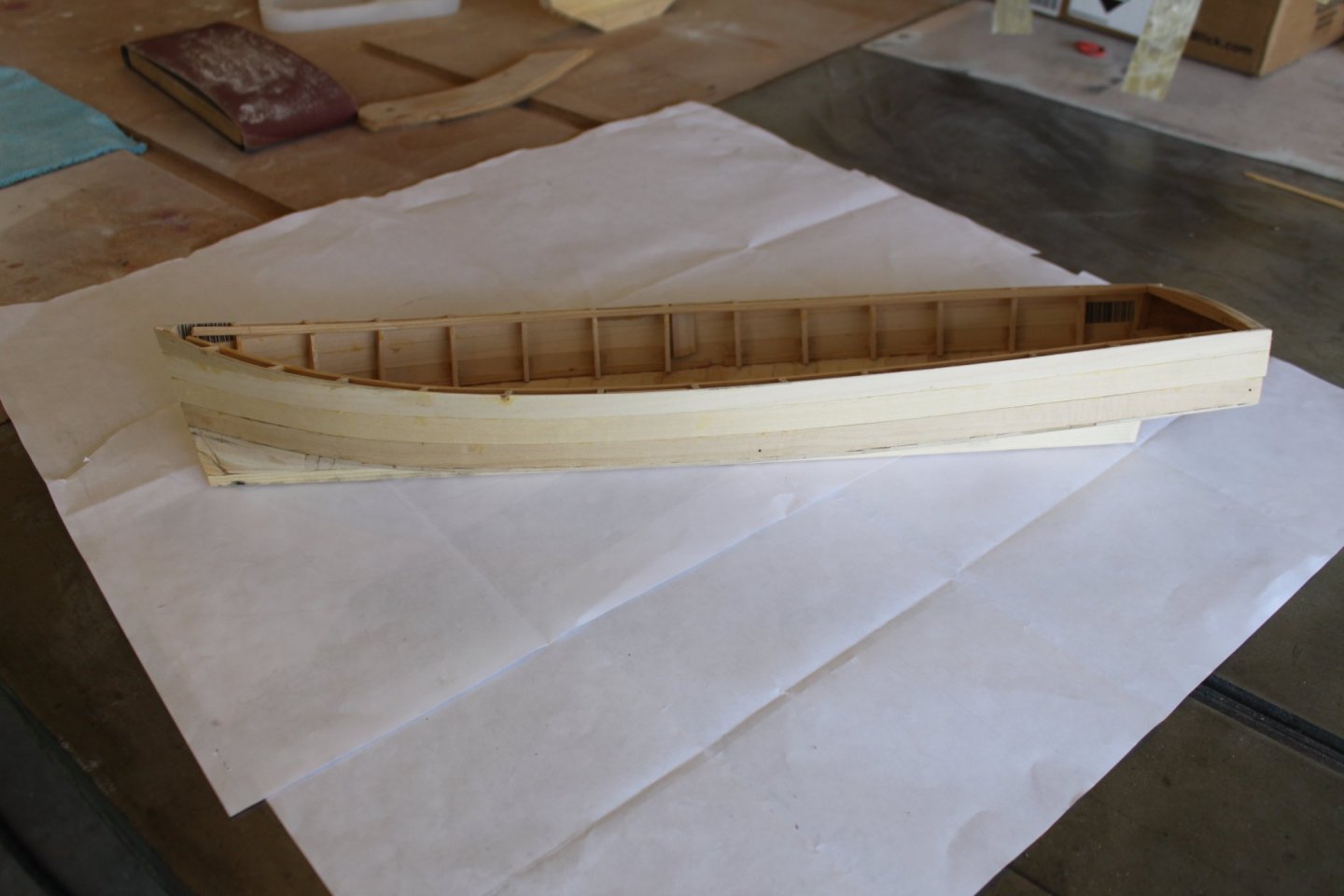
At this point the instructions wanted me to start planking the bottom. I quickly realized that it had made no mention for the need to slightly bevel the bottom of the keelson for the planks to have a gluing surface. I used a straight edge and a block plane to form the bevels. Next, I realized that the instructions did not have me install a “chine log” at the bottom of the first hull plank. The chine log doubles the thickness of the hull plank, strengthens the chine and increases the gluing surface for the bottom planks. I glued a strip of 1/16” x 1/8” wood to the inside bottom edge of the first hull plank. It was glued so that it hung down a bit in order for it to have a bevel sanded on it that would correspond to the angle of the bevel on the keelson. I use a sanding block that is about a quarter inch thick, an inch and a half wide and about ten inches long to sand the chine log. It has sandpaper on one end and nothing on the other. This allows me to let the paper sand the area I need it to while the other end rests on the keelson and helps create the corresponding angle without re forming the angle on the keelson. Once those tasks were completed, I proceeded to plank the bottom of the hull. Sorry for not taking pictures of the afore mentioned process. Here’s a picture of the hull now that it has been mostly planked . Notice the chine logs where the bottom planks meet the hull plank. Once again, the experience from my previous build and the knowledge I gained from this site has severed me well. Thank you. `

- 20 replies
-
- 6
-
-
- Breezin Thru
- Wye River Models
- (and 1 more)
-
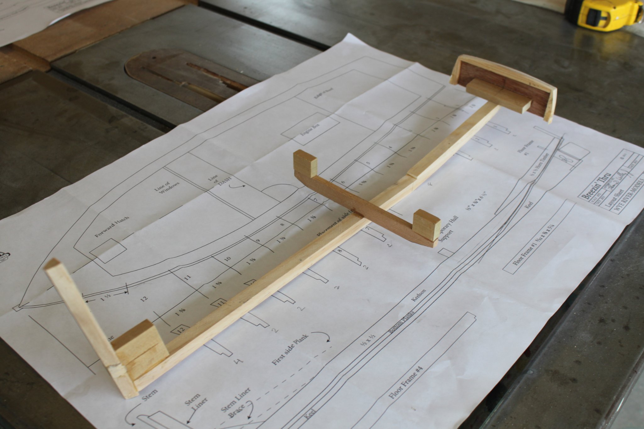
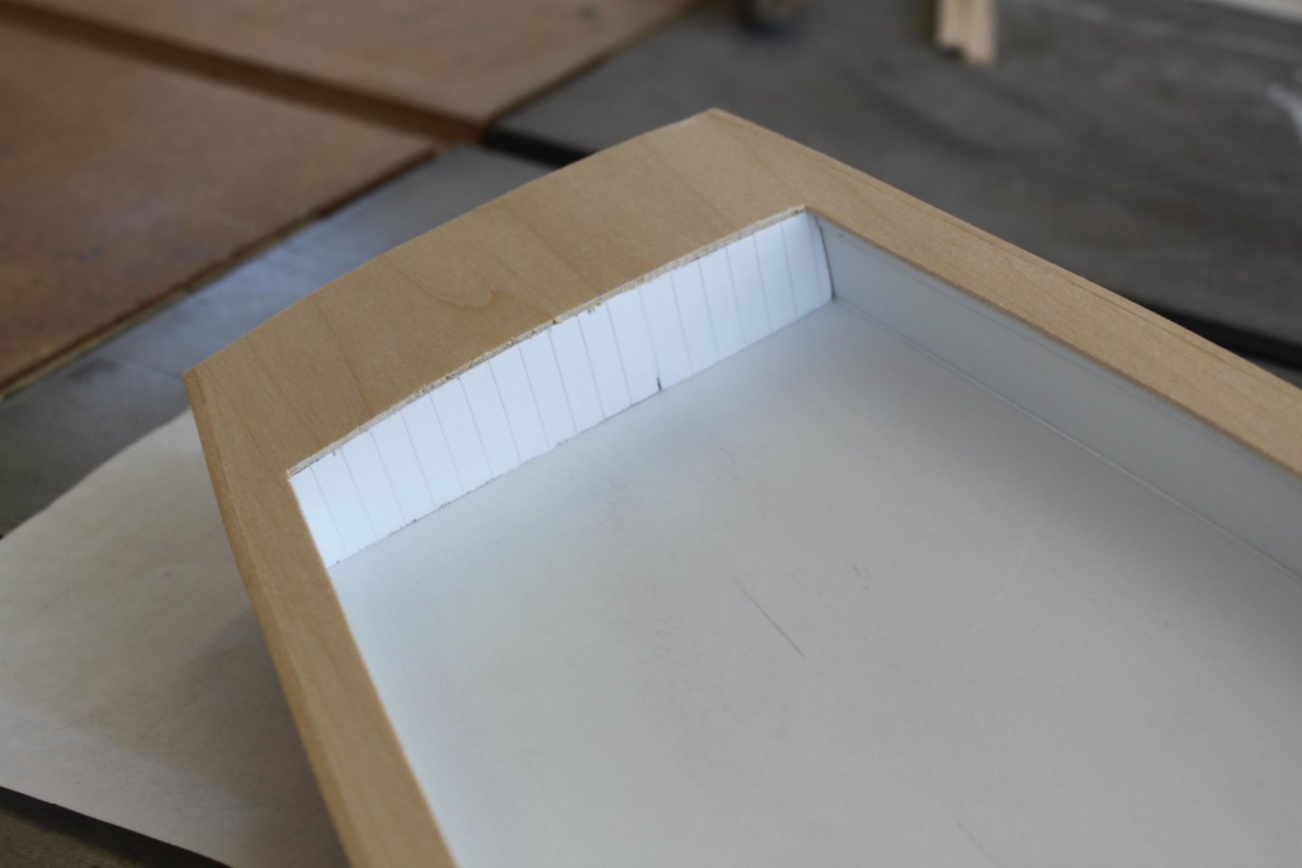
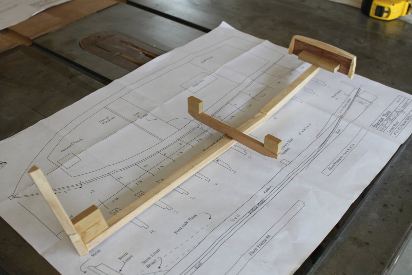
This manufacturer uses a method where they have you produce what they call a “Keelson”. It starts by having you cut a ½” x ½” piece of wood at an angle to create an inverted scarf joint. This joint produces the angle of the stern section of the hull. After gluing, it needs to be sanded into its final shape and then have the transom attached. In this case a (roughly) precut transom was supplied. It was not symmetrical and did not match the template. To make matters worse, the template was not symmetrical either. I carefully sanded it into a symmetrical shape and attached it to the end of the keelson. Drawing from the experience I gained during my Skipjack build, I realized that simply gluing the transom to the end of the keelson would not create a strong joint. Nor would it hold the transom square to the keelson. My solution was to add additional blocking that would hold it square and increase its strength. I also added extra blocking to the inside perimeter of the transom in order to increase the gluing surface for when the bottom planking and decking were attached. None of these improvements were suggested in the directions The forward end of the keelson has what they call a “Stem liner” attached to it. It is another ½” x ½” piece of wood that is cut on one end to achieve the angle of the rise of the bow. It also has angles cut on the port and starboard sides of it so that it provides a gluing surface for the hull planks. A block at the joint helps give it strength. At this point the keelson was built exactly to the template provided as possible. This is when I noticed another potential problem. The Keelson did not appear to be as long as the plan drawing of the deck. It was hard to tell for sure because the hull would eventually flare out wider and be a little bit longer. After carefully plotting out the finished height and positioning the keelson on the hull template it became obvious that it was a half inch short. I decided to go with what I had and make adjustments as I went along. The fourth and final step to producing the keelson was to attach what they call a “strong back”. It is another stout piece of stock that is attached to the keelson at a right angle. It controls the width of the boat at its widest point and forms the shape of the hull when the first plank is attached. As you can see in the picture, the shape produced was not even close to the shape of the deck template. The two hull planks were removed, and additional strong backs added to achieve a shape that was within reasonable parameters. It was a little tricky to determine what it should actually be because the hull would eventually flare out wider as it approached the deck height. I'm much more satisfied with this shape. `
- 20 replies
-
- 7
-
-
- Breezin Thru
- Wye River Models
- (and 1 more)
-
Shore thing reacted to a post in a topic:
Breezin Thru by Shore thing - FINISHED - Wye River Models - 1/2" scale
-
As Forest once said, "You never know what you're going to get". Fortunately, this model is not that complex. The biggest problem is that it lacks the details that are needed to make it look as close as possible to the real boat. To quote my high school moto "Find a way or make one". A nd that is what I will do.
- 20 replies
-
- 2
-
-
- Breezin Thru
- Wye River Models
- (and 1 more)
-
“Breezin Thru” is a classic Chesapeake Bay charter boat. Here is a quick historical review of the boat from the Wye River Models instruction manual. “The “Breezin Thru” is a charter fishing boat that was built in Rock Hall Md. In 1949 by Andrew J. Stevens. It is 44’8” long and 13’6” wide. It has been in continuous service since it was built. The boat was originally owned and captained by Harry Carter, but is captained by it’s present owner Tilghman Hemsley. Tilghman is a renowned artist whose most notable work is the Maryland Waterman’s Monument displayed at Kent Narrows in Grasonville, MD” This is my second wooden boat model and once again I chose a Wye River Models kit to build. There are several reasons for that decision. The main reason is that they offer models that are classic boats styles that have been primarily used on the Chesapeake Bay for decades. I also like to support local small businesses. After having built one of their most difficult models, (The Skipjack) I wanted an easier (no rigging) build. I also felt that the experience I gained from my first build would help me navigate thru their building style. With that said, and in order to help others, an honest review and my opinion of the kit is necessary. The kit. Upon opening the box, I found exactly what I expected, another “jumble of sticks”. There was also a material list, instruction booklet, two sheets of full-size drawings/templates and a hardware packet. After reviewing the material list, I found several items to be missing. The hardware packet did not have the cleats (2) in it nor plexiglass for the windows. Scrap wood for the cradles and blocking was not included. Wood for the chine logs also seemed to be missing and wasn’t even mentioned on the material list. This will be discussed further as the build progresses. The full-size drawings/templates were labeled NTS, not to scale. That in itself is not unusual. It is well known that during the printing process drawings can change size slightly. One of the problems is that there are very few measurements labeling the overall lengths, widths and heights of the components. Another is that the templates are not symmetrical. For example, the curve of the port side of the transom does not match the starboard. When the plan view of the boat was folded along the center line, it also did not match. As I build the model, special attention will need to be given to those issues in order to ensure the boat is symmetrical from side to side. The instruction manual can best be described in two words, “woefully inadequate”. It is an eighteen-page booklet with twenty-nine black and white photos and several templates of items that would not fit on the full-size drawing sheets. There is one picture of the finished model on the cover and one of the actual boat afloat in its slip. There is also an artistic rendition of the boat at work on the back cover. Irony, you never know when it will pop up. My first wooden ship build was the “Skipjack” by Wye River models. Other than the Bugeye, it is one of their most advanced models. At the time of the build, I complained that the instruction manual that came with it was more of a guide than step by step directions. Boy was I wrong. And my successful build proves it. The instruction book, “The Skipjack” by Steve Rodgers and Patricia Staby – Rodgers was in fact an encyclopedia in comparison to the instructions supplied with this model. It is seventy- nine pages long and contains more than two hundred color photos and drawings. The irony is that I am referring to it while building this model. Now, on to the build.
- 20 replies
-
- 4
-
-
- Breezin Thru
- Wye River Models
- (and 1 more)
-
Shore thing reacted to a post in a topic:
Skipjack by Shore thing - FINISHED - Wye River Models - Scale 1/2" - First wooden ship build
-
Shore thing reacted to a post in a topic:
Skipjack by Shore thing - FINISHED - Wye River Models - Scale 1/2" - First wooden ship build
-
In closing. I never imagined that this journey would take almost four years to come to fruition. Granted, the model spent a good bit of that time not under construction and just sitting on a shelf collecting dust. Regardless of that, there were many, many hundreds of hours invested into the building of the model and all the research that was necessary to build it to the best of my abilities. It got to a point where the research was as fun and interesting as actually building the model. I read a small library’s worth of books and traveled to a good many locations in order to see some of the few remaining boats in person. Fortunately, there are a number of opportunities on the eastern shore where they can be seen. Several of them are here in Cambridge. We are lucky enough to have not only the “Lady Katie” and the “Nathan” still afloat, but the town has a shipyard that was until recently storing two others that need to be restored. It now has one of “Lady Katies” sister ships, the “Martha Lewis” in its yard undergoing an extensive renovation. The Town also hosts the annual Skipjack race. Add to that, there’s the Chesapeake Bay Maritime Museum in St’ Michaels. They have the third sister ship to the “Martha Lewis” and the “Lady Katie, the “Rosie Parks” as well as the “H. M. Krentz” and the “E. C. Collier”. Taking trips to these locations and events has given my wife and I many hours of enjoyment. It has also helped me learn more about Skipjacks than I ever though I would. The building of this model presented me with too many challenges to mention. Starting with the overwhelming sense of intimidation I felt upon opening the box and staring at a jumble of sticks, to learning to sew, do metal work and tie knots in thread for rigging. With the help of this site, I was able to hone my skills and gain the confidence needed to make the many improvements that brought the model up to a more accurate example of a Skipjack. This site also gave me an even greater appreciation for those of you who build models such as frigates, cutters, schooners or anything else that has more than a few feet of rigging. The amount of effort and skills that have been demonstrated by so many of the members is amazing. Beautiful work people. Thanks to everyone who followed my build, made suggestions, gave positive comments and for all the “likes”. I will post an album sometime in the near future. In the mean time I have already purchased and started building another model. Stay tuned. Reed
- 82 replies
-
- 4
-
-
- skipjack
- wye river models
- (and 2 more)