Peter, your writeups have been very inspiring. Thanks for exposing the twists and turns you've encountered in exploring how Fusion 360 can meet your needs. I've also been using that software to model hull shapes for another goal. I own a classic sloop that needs modification of the cockpit area in order to shoehorn in a new powerplant. The engine manufacturers provide 3d models of the entire drivetrain, so it sure would be nice to have a realistic model of the hull and interior framing.
I started with as-built line and offset drawings for my boat, a 1962 Cheoy Lee Lion designed by Arthur Robb, with a carvel planked teak hull. The as-built blueprints are archived at Mystic Seaport Museum and are available for a small fee. I used a similar procedure as you described in a previous post, but used the body plans as profiles at 12 stations and just one of the buttocks as the (single) rail. I tried using the rabbet line and/or the rail top as rails, but got errors about crossing rails, etc. I had to do something similar to your second method to splice in (merge) the drawing at the bow, but other than that the loft was automatic from stern to bow.
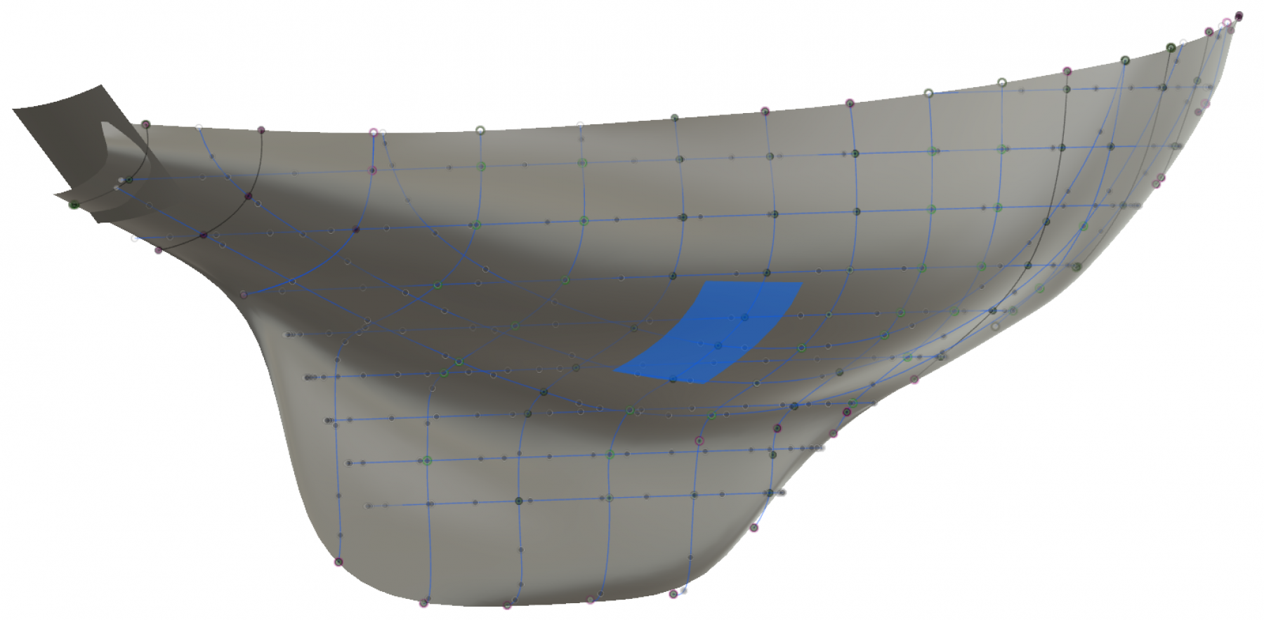
However, a lot of detailed manual sculpting is required to make up for deficiencies in the automatic loft. Although the detailed plans have 12 stations, 8 waterlines, 3 buttocks, plus the rabbet and top rail, the loft still had a wavy appearance no matter the settings on the t-spline grid spacing.
But, I guess some hours of detail work with a mouse is worth it. The t-spline editing tools are very powerful, and eventually I have a hull model that does conform to the design. Yesterday, I spot checked some measurements on the actual boat, and there are a few centimeters difference in places. But good enough for now, and it's time to add some framing to the hull and then bring in the drivetrain model.
Jim


 pointfiftytracer reacted to a post in a topic:
An attempt at hull modeling with Fusion 360 Loft + Rails
pointfiftytracer reacted to a post in a topic:
An attempt at hull modeling with Fusion 360 Loft + Rails