robcg
-
Posts
26 -
Joined
Recent Profile Visitors
445 profile views


-
 mtaylor reacted to a post in a topic:
Arrangement of floor timbers
mtaylor reacted to a post in a topic:
Arrangement of floor timbers
-
Arrangement of floor timbers
robcg replied to Mark P's topic in Building, Framing, Planking and plating a ships hull and deck
Hi Mark, Would a framing arrangement with four filling frames between every pair of bends make sense here? At this point in the century, six filling frames were the norm between bends, but four are also possible. There is a distance of 3x the room and space between your bend at 9 and your bend at 12, and each interval of the room and space contains room for two timbers (a floor and a lower futtock). For instance: a bend centred on station line 9 would include a floor on the aft side of the line, then we would see a filling frame with a lower futtock just aft of that, then we hit station line 10, then a filling frame with a floor (which was apparently difficult for the yard to obtain), then a filling frame with a lower futtock, then station line 11, then a filling frame with a floor (again difficult for the yard to obtain), then a bend centred on station line 12 with its lower futtock on the forward side of the station line. The NMM model of the Dolphin of 1731 (SLR0226, see NMM website) shows, in a stylized fashion, such an arrangement in its fore and aft bodies. Something to mull over. That said, I agree that if you double all the frames, nobody will be able to prove you wrong. Rob -
timboat reacted to a post in a topic:
trunnels (tree nails) vs metal nails use
-
tkay11 reacted to a post in a topic:
trunnels (tree nails) vs metal nails use
-
Canute reacted to a post in a topic:
trunnels (tree nails) vs metal nails use
-
Jeff-E reacted to a post in a topic:
trunnels (tree nails) vs metal nails use
-
mtaylor reacted to a post in a topic:
trunnels (tree nails) vs metal nails use
-
Take a look at William Sutherland's Shipbuilding Unvail'd, written in 1717 and very applicable to your project. The hyperlink is to the free online copy. Pages 75 to 96 of the text (57 to 68 on the online viewer) include a template for a British ship's contract. Unfortunately, the dimensions are left blank, but at least it will tell you which components use bolts, which use nails and which use trennels. The 1719 Establishment also has some information on bolts (including diameters). Peter Goodwin's Construction and Fitting of the Sailing Man of War has a transcription in the appendix, and Allan Yedlinsky's book Scantlings of the Royal Navy includes the Establishment data as part of the tables. Hope that helps, Rob
-
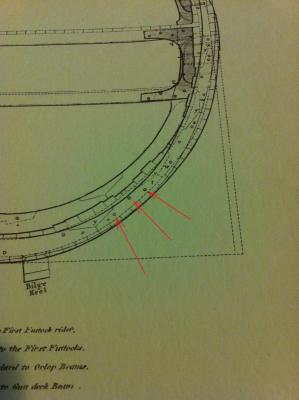
Alan, My suggestion would be that the 1-1/4" bolts are driven fore and aft, through your filling pieces, with three tying the top half of the floor to the bottom half of the first futtock, three tying the top half of the first futtock to the bottom half of the second, and so on up the frame. See attached excerpt for a 74 showing these bolts. In this case, the ones being pointed out are securing the overlap (the term "scarph", in this sense, meaning nothing more than an overlap) between the first and second futtocks. Steel's tables show, for a 74, that these bolts would typically be 1-1/4". Steel goes on to mention the joining of the heads or heels of the timbers into the chocks. For a 74, the excerpts is: "The Heels of the Futtocks to run down to the Deadwood, and to have substance left there" equal to 6 inches (meaning the lower futtocks). "Not to have less stepping or substance at the Heels of the Double Futtocks, and Half Timbers" than 3-1/2 inches (double futtock meaning a point where a futtock head meets a futtock heel at the chock), "and the Heels bolted with bolts, in diameter" equal to 1-1/8 inches. All that just to say that, at their thinnest point at the midpoint of the chock, the timbers must maintain a certain minimum thickness, and the bolts that go through should be slightly smaller in diameter than those binding the timbers fore and aft. Take care to ensure that the bolts fore and aft don't interfere with the bolts through the chocks (they're shown awfully close to one another in the attached pic). Image from Steel, Naval Architecture, Plate 8. Excerpt from Steel, Naval Architecture, Tables/Folio V. In the interests of full disclosure, I'll confess that late 18th century stuff is not my strongest suit, and it's entirely possible I'm out to lunch on this. If Druxey is not convinced by this, then perhaps more research is needed. Ultimately, I defer to him on such issues.
-
Steel's Naval Architecture - tables - folio V has a very similar statement under "Frame-Timbers". The first through fourth futtocks and the toptimbers are to be scarphed or framed together and bolted with either two or three bolts per scarph, depending on rate. The bolt diameter is specified and then it is mentioned that the lower futtocks are to be bolted to the floors in the same manner. The only way I see the lower futtocks being fixed to the floors is with a fore-and-aft fastener. The remainder of his scantlings for the various timbers typically specifies the scarph length of one timber to the next (i.e. 1st futtock to scarph with the second, second with the third & so on). I'm pretty sure the three bolts are intended for these fayed scarphs, not the chocked scarphs.
-
Might this line in the contract alternatively indicate that there were to be 3 fore-and-aft bolts in each scarphing section between the fayed timbers in a bend? i.e. three bolts to join the top half of the 1st futtock to the bottom half of the adjacent 2nd futtock, etc. Steel's Naval Architecture has a plate with midship sections showing 3 fore/aft bolts in each of these timber scarphs, and I believe this was a common arrangement. The scarphs joining the timberheads to the chocks would obviously also need to be bolted, and I'd definitely buy Druxey's illustrated arrangement for them, but I'm not sure that's necessarily the set of bolts being specified in that line of your contract. Rob
-
Peter Goodwin (Sailing Man of War, 1987, pg.15,16) and C.N. Longridge (Anatomy of Nelson's Ships, 1981, pg.19) both call them "lengthening pieces". DH Roberts' translation of Blaise Ollivier's Remarks on the Navies of the English and the Dutch (1992, pg.65) calls them "fifth futtocks", but this is a translation of Ollivier's best guess on the subject. Generally, I believe they're also occasionally called "filling pieces". This seems to be the case whether they're above a port sill, as in your example, or attached to an unbroken bend.
-
robcg reacted to a post in a topic:
Joshua Humphreys' Notebook
-
robcg reacted to a post in a topic:
Wood Preservative/Stabilizer
-
robcg reacted to a post in a topic:
Wood Preservative/Stabilizer
-
Hi All, A few articles I've come across in model making or woodworking magazines have mentioned specialty wood sealers & stabilizers. Specifically, Pentacryl and Cuprinol are noted as having been used with some success in model ship building or restoration. Anybody have any experience with these products (ship modelling or otherwise)? If so, how'd they work out? Thanks, Rob
-
Hi Russell, For authoritative details on a capstan from the early 18th century, check out William Sutherland's book Shipbuilding Unvail'd, which has one of the earliest known descriptions for both a main and a jeer capstan (pages 63-65). This book is available for free viewing online at: echo.mpiwg-berlin.mpg.de/ECHOdocuView?url=http%3A//content.mpiwg-berlin.mpg.de/mpiwg/online/permanent/shipbuilding/Suthe_Brita_01_1717/index.meta&start=51&viewMode=auto&pn=51&mode=texttool The book was a compilation of Sutherland's experiences working in the Royal Dockyards from about 1696 to 1717, so it's very applicable to your project. Now, Sutherland lays out the dimensions of all the parts of his capstan based on proportions, so you must have the dimension of at least one component of a capstan to use as a starting point. Sutherland uses barrel diameter as his base dimension. The 1719 Establishment specifies diameter of the capstan's spindle in the partners (1ft 8in for a 50 gun ship). Using Sutherland's comment that spindle diameter is 19/21 of the barrel diameter, you get a barrel diameter of about 22 inches to use as your reference. From there, follow his instructions and illustrations to get the size and shape of the rest. Check out Lavery's Arming and Fitting of English Ships of War for additional detail (this should be available for sale on Abebooks.com or through an inter-library loan at a public library). Hope that helps, Rob
-
Allan, I'd agree that Sutherland's plates are more like suggestive illustrations than technical draughts, and should be used with caution. Sutherland's text (pg.35,38,39) makes very clear that the frames should be used at, or near, the sides of the ports and that the principal frames must never be cut by the ports - in direct contrast to the illustration. There are a few other examples of his text and his plates being somewhat contradictory, with the plates being the less reliable. It may be of interest to you that Sutherland's text (pg.35) explicitly mentions the use of cant frames in the bow, but he never mentions cant frames in the aft section of the hull. Plate 38, above, is drawn accordingly. Perhaps cant frames in ship's bows were introduced prior to 1711, and followed by the inclusion of aft cant frames sometime between 1711 and the construction of SLR0405 in 1715ish? Wayne, Thanks so much for your post. I had not seen the Northern Mariner article, and now I've got some weekend reading ahead of me. You're correct that Steel is a bit removed from the 1719 Establishment! Since Sutherland is not always as detailed as I'd like him to be, I've been forced to occasionally interpolate from Steel, Mungo Murray, or Anthony Deane. I greatly appreciate your help on this issue! Cheers, Rob
-
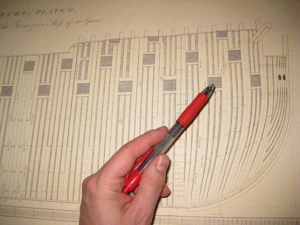
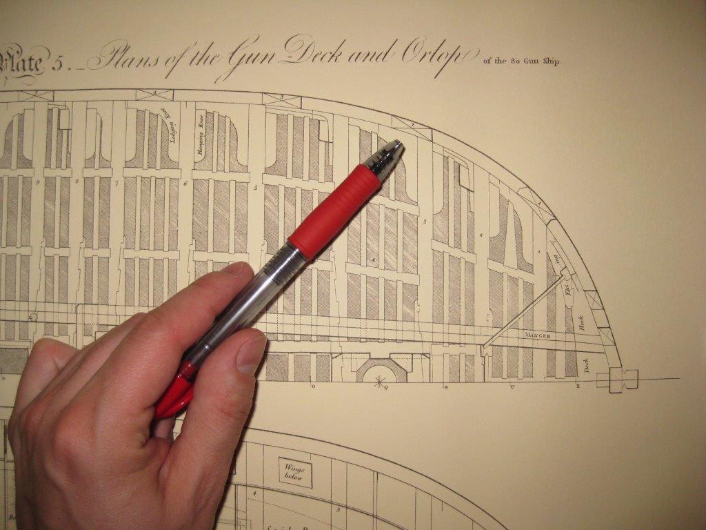
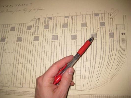
Thanks Wayne, I greatly appreciate your help! I've attached some photos of the plans that have caused this problem for me... The first is from Plate II of Steel, and shows the second gunport on the gundeck is clearly framed by cant frames. The second photo is from Plate 5, and shows that the port is cut perfectly perpendicular to the center axis of the ship, cutting through the cant frames instead of lying on the same axis with them. This seemed odd to me, and has been causing me some grief as I try to finish a disposition of frame plan for a ship of the 1719 Establishment. If Sutherland wrote something on the topic, I completely missed it. Clearly I'll have to go over my notes again! Cheers, Rob

-
I think Longridge is, indeed, speaking of the tilt imparted by the sheer of the deck. Wayne, if you've got something which indicates that the ports are to be "aligned with the shape of the hull", that would probably be what I'm looking for. It matches Nigel's explanation of ports following the axis of the cant frames, which seems to me to make the most sense. If you can let me know where you got that info, I'd appreciate it. Rob
-
Hello Everyone, I'm hoping to get some advice regarding the gunport framing for an early 18th century English ship. Most deck plans that I've seen show the gunports perfectly perpendicular to the main axis of the ship, even afore and abaft, where the hull curves inwards towards the centerline. Sheer plans, however, often show the foremost ports shortened in the fore and aft direction, as if they were set normal to the curvature of the hull, not perpendicular to the center axis. Furthermore, having the ports angled in this manner would seem to work best with the cant frames in the fore and aft sections of the ship. Does anyone have any info or reference to show whether the gunports were all set perpendicular to the center axis, or if they followed the curve of the hull in the fore and aft cant-framed sections? Thanks, Rob
-
Thanks very much for your help Allan and Druxey! I've got a few additional questions on these scantlings, but perhaps I'll start a new thread for each. Once again, well done on this compilation, Allan. It's fantastic to see this info made so much more accessible. Cheers, Rob
-
Hi Alan, I just received my copy of your scantlings book, and wanted to let you know how pleased I am with it. It’s certainly a lot of data crammed very efficiently into a small number of pages! I see, from the previous posts to this thread, that you’ve offered to provide some further explanations or definitions for anything contained in your tables that might not be clear. I thought I’d take you up on that, and I’ve got a few questions regarding the 1719 Establishment that I’d love to hear your opinion on. To start with: In folio 4, line O, the specification lists a measurement for the stem “Below the hance" I understand a hance to be a sudden discontinuity in a smooth line, but I’m not sure what the hance on a stem might be. To what part of the stem should this scantling apply? Any detail on this from you (or anyone else) would be greatly appreciated! Thanks, Rob