xodar461
-
Posts
162 -
Joined
-
Last visited
1 Follower

About xodar461

Recent Profile Visitors
1,566 profile views


-
 Papa reacted to a post in a topic:
Foss Landing and The shipyard at Foss Landing by xodar461 - Sierra West Scale Models - 1/87
Papa reacted to a post in a topic:
Foss Landing and The shipyard at Foss Landing by xodar461 - Sierra West Scale Models - 1/87
-
 Baker reacted to a post in a topic:
Foss Landing and The shipyard at Foss Landing by xodar461 - Sierra West Scale Models - 1/87
Baker reacted to a post in a topic:
Foss Landing and The shipyard at Foss Landing by xodar461 - Sierra West Scale Models - 1/87
-
ERS Rich reacted to a post in a topic:
Foss Landing and The shipyard at Foss Landing by xodar461 - Sierra West Scale Models - 1/87
-
Canute reacted to a post in a topic:
Foss Landing and The shipyard at Foss Landing by xodar461 - Sierra West Scale Models - 1/87
-
gjdale reacted to a post in a topic:
Foss Landing and The shipyard at Foss Landing by xodar461 - Sierra West Scale Models - 1/87
-
wefalck reacted to a post in a topic:
Foss Landing and The shipyard at Foss Landing by xodar461 - Sierra West Scale Models - 1/87
-
GrandpaPhil reacted to a post in a topic:
Foss Landing and The shipyard at Foss Landing by xodar461 - Sierra West Scale Models - 1/87
-
Jack12477 reacted to a post in a topic:
Foss Landing and The shipyard at Foss Landing by xodar461 - Sierra West Scale Models - 1/87
-
Egilman reacted to a post in a topic:
Foss Landing and The shipyard at Foss Landing by xodar461 - Sierra West Scale Models - 1/87
-
JacquesCousteau reacted to a post in a topic:
Foss Landing and The shipyard at Foss Landing by xodar461 - Sierra West Scale Models - 1/87
-
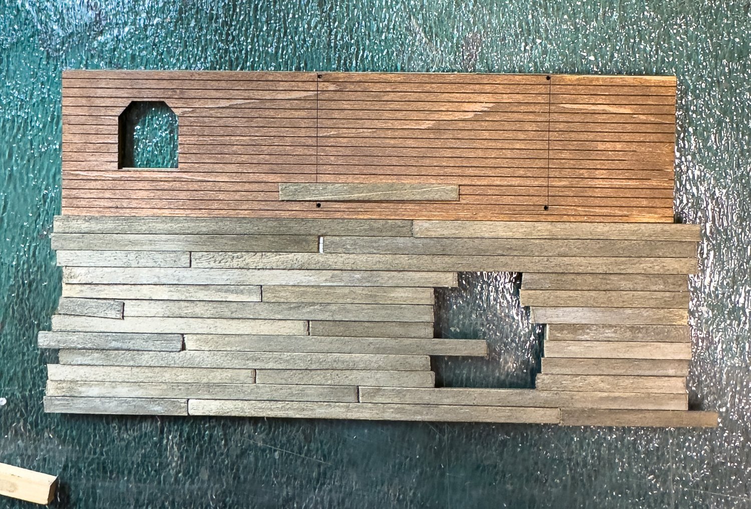
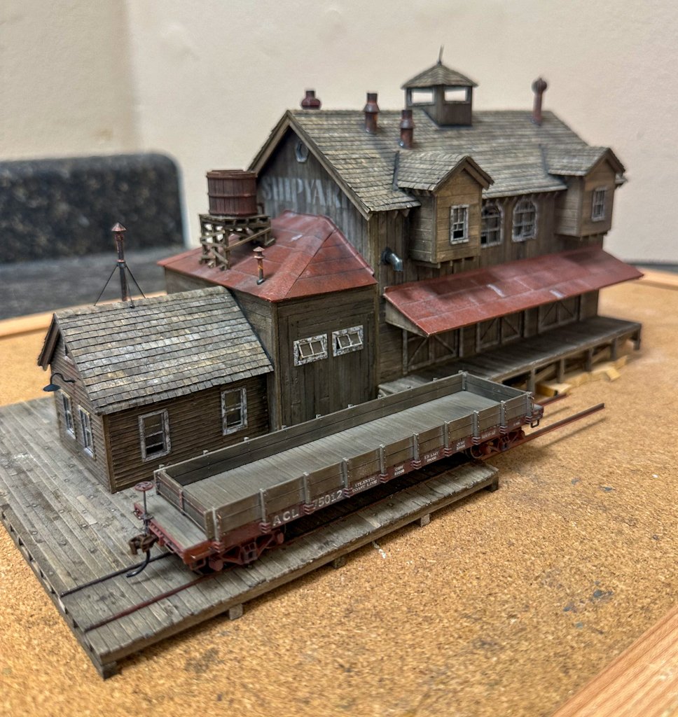
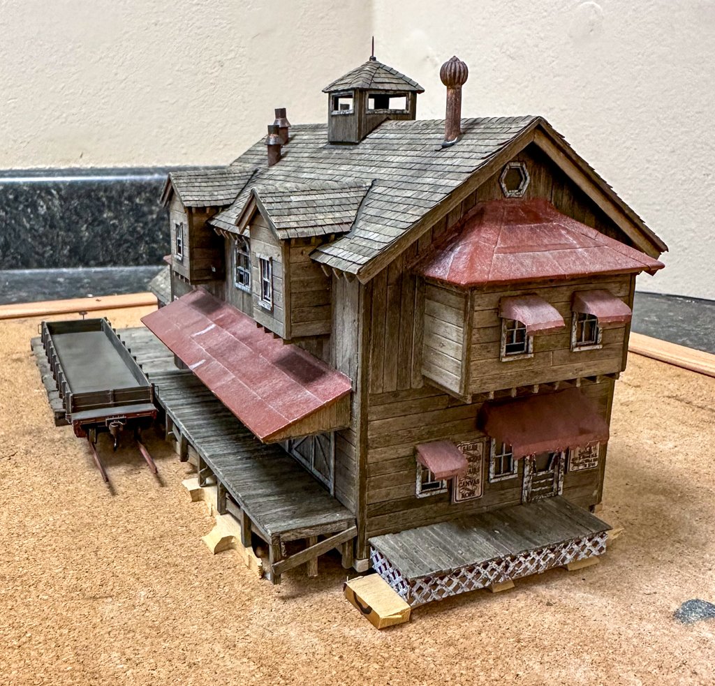
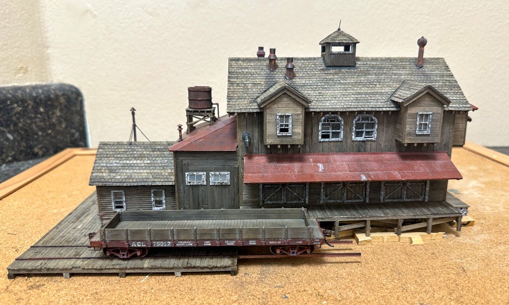
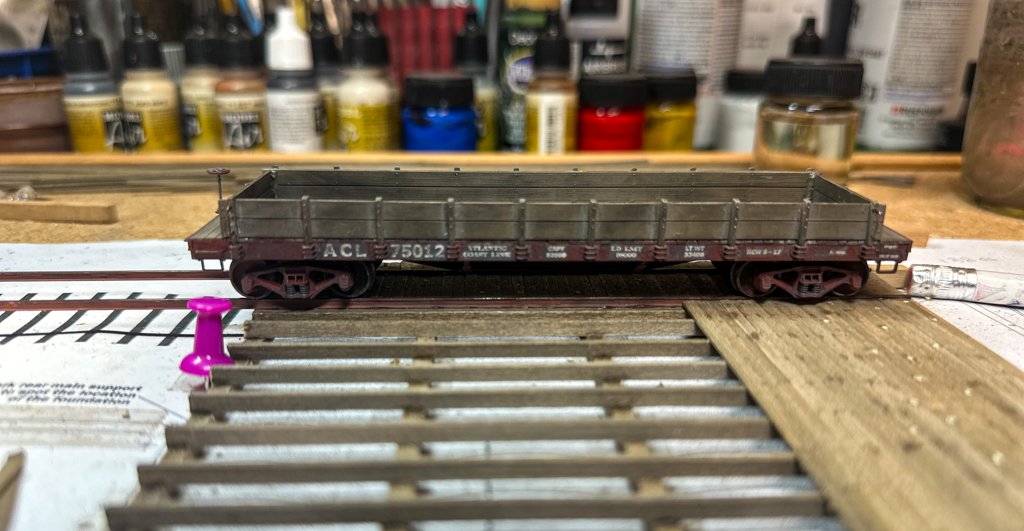
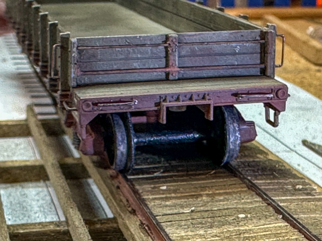
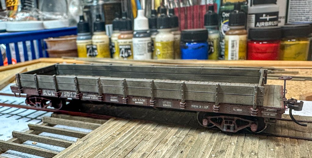
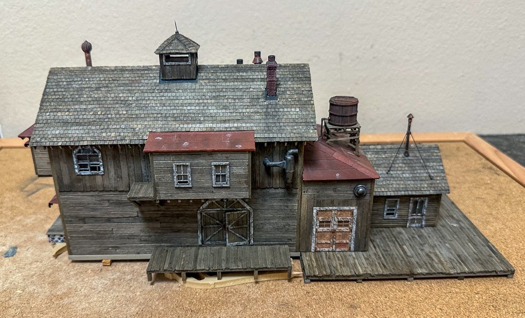
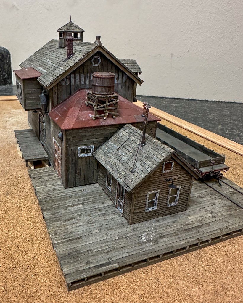
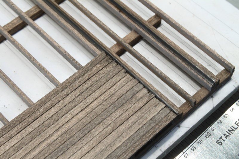
 Greetings! Work continues on the main dock. The knots in the boards were randomly placed after the boards were glued to the beams. When all the boards are down, they will be given a wash with A/E to darken the knots. I decided to lay the planks to the red line (see photo, last post). I put together a scale 40-foot flat car and the trucks run quite smoothly over the tacks with the wood placed so. I also like the look of the track "buried" in the deck. Here are a few photos. And finally, the main building on the foundation beams and the deck. Some wood scraps were used beneath the foundation and the various platforms to get them all at the correct height. I need to straighten the rod at the top of the cupola as it seems to be off in one axis. Next up, 2 small sheds and the saw shed. jeff
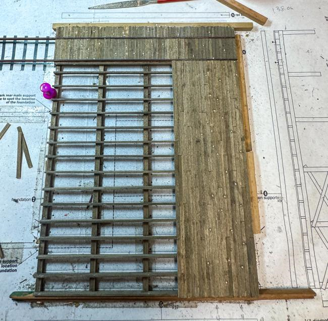
- 68 replies
-
- 12
-
-
-
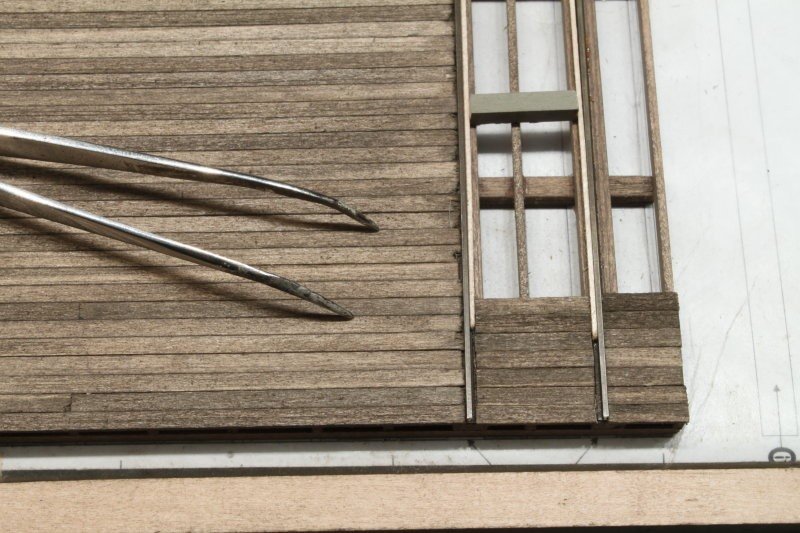
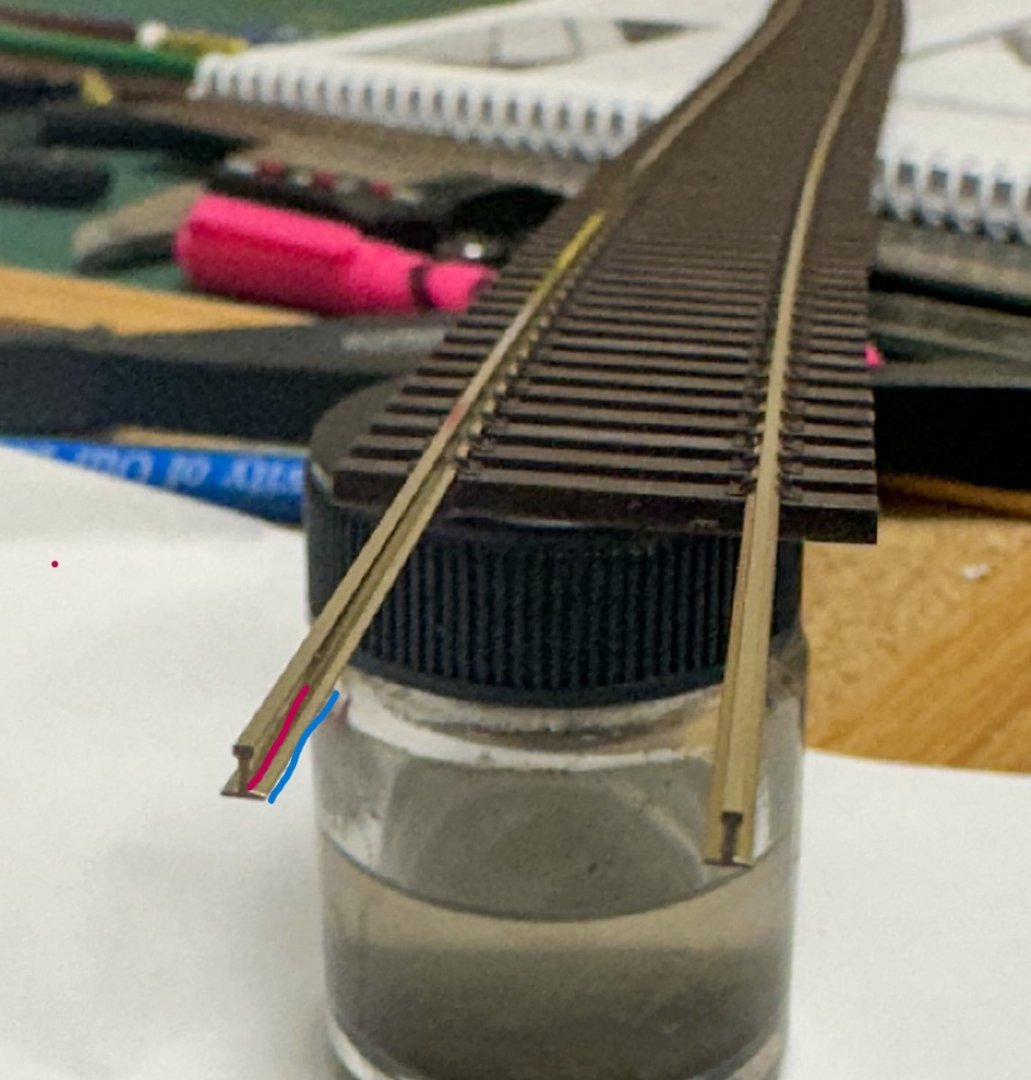
Welfack and Ken, thanks for the advice. I did a test by placing a plank between the rails covering the base and there was no interference with the wheel as it rolled freely down the track, so I'll forgo any spacer for the inner planks (the white plank seen in photo above) and have the boards go right up to the rail. I will post some in progress photos when I get to that part. Jeff
-
These photos were taken from a log on the SW forum and shows how the rails go on the planks. On the outside of the rail, the boards cover part of the rail base almost up to the rail. On the inner part a plank is used as a spacer to allow for the wheel flanges. I'm building a flatcar that will be incorporated into the diorama, so I'll see if there is enough clearance for the wheel flange if boards cover the rail base on both sides. It seems to me that if only half of the base is covered, the rail would be unstable. And a dock / platform like this does not seem to be an optimal location for spikes. I'll see if I get any answers from the SW forum. jeff
-
Thanks for the replies. Welfack, when I copied and pasted the post from the Sierra West Forum, initially the URL was seen and not the photos. I think you got to the post before I edited it as now the photos are visible. As far as where the planking ends at the rail, if it stops at the edge of the rail, then I would assume that you would then need spikes to hold the track down like you would have with RR ties. None of the build logs on the SW forum mention this. Re: comment by Canute, I was not implying to remove any of the rail base, but rather should the wood planking cover the flange part of the base up to the rail itself. The multiple planks would server to keep the rail anchored and obviate the need for spikes. I am not sure the wheel flanges would go low enough the hit the wood. I have a rail flatcar that will be part of the diorama so I may test this out. Jeff
-
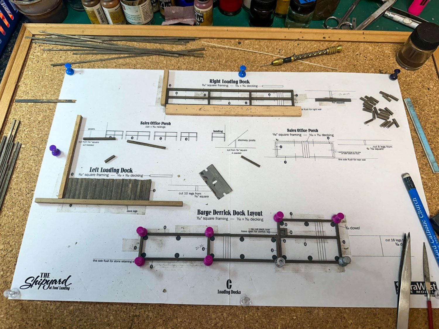
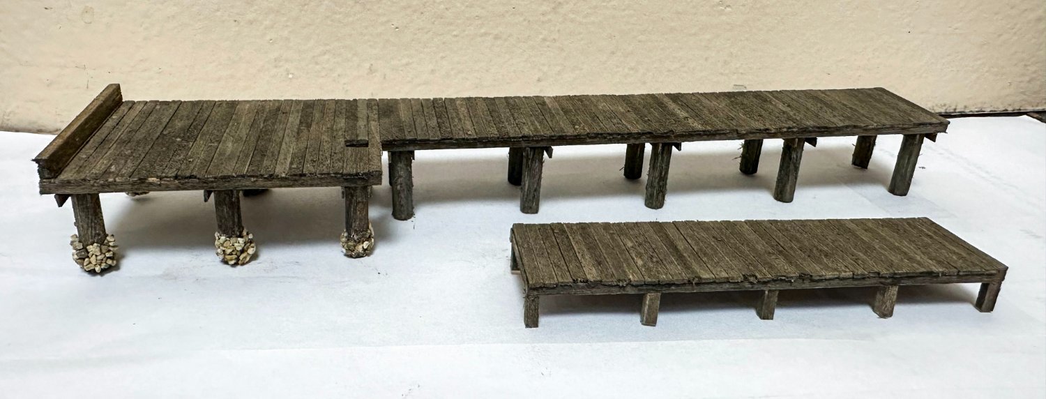
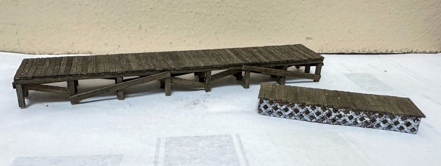
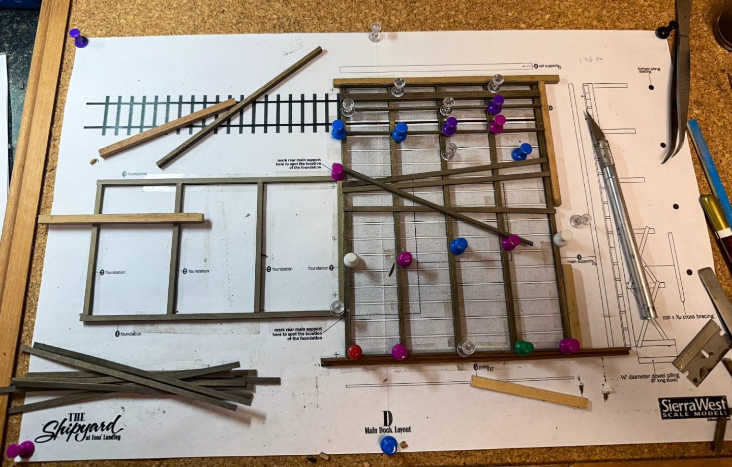
Greetings! Work continues with the docks. Template C has the right, left and derrick docks and the sales porch, all done simultaneously. Here is some early progress. The completed docks below. Instructions are very clear cut. Fine ballast was used to create the barnacles on the supports that will be underwater. One variation from the instructions - I decided to paint the skirting speckled white. I found that on many porches, this part was white. I'll probably make the railing white to match. This will be similar to the stairs and railing of Foss Landing. Note that on the derrick dock, I made the height of the "barnacles" less as the dock went inland as the water level would be lower. Now onto the main dock. Here is some preliminary work. I have a question for the any RR enthusiasts out there (not sure there are many here at MSW) - for the rails that are on the dock, where should I terminate the deck planking - at the blue line or red one? I can't seem to find many photos of this online and the pic in other build logs are too low resolution. As always, thanks for the kind comments and thanks in advance for any help on my questions. Jeff


-
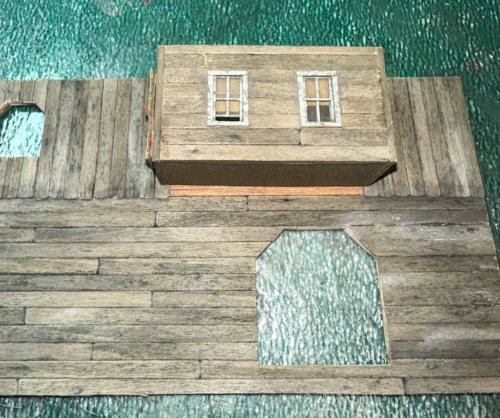
Greetings! The office has been attached to the main building and the pitch and pine tar tank and platform were completed and glued to the warehouse roof. A small hole was drilled in the roof top accommodate the pipe. Here is the structure thus far. First, a few close ups of the tank and platform... ...and the main building. Several stacks are being prepared to glue onto the roofs. Then onward. Jeff
- 68 replies
-
- 11
-
-
-
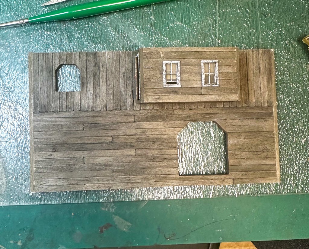
Greetings! Work continues on the main building. The attached warehouse is complete. Not much extra to add from the instructions though I did add some beams behind the metal doors for some support. See photo below, upper right. I had to salvage some scraps from the wood pile to complete the walls. Here is the competed wall and doors. The roof goes on much like the awnings on the main building. Here are some photos of the warehouse attached to the main structure. One LED was added to the interior of this section. Excuse the simulated bird poop on the warehouse roof! The Yardmaster office is next. The clapboard siding was fun to build and if you look closely, there are boards that are split, chipped and a few that have part of the board missing. Roof is almost complete in these photos. The office will have one gooseneck light on the gabled side and one LED inside. Once glued to the main structure, it's onto the items located on the roof. Jeff
- 68 replies
-
- 11
-
-
-
Greetings! It's time for the roof and shingles. A long beam is first glued between the end walls to give the cardboard base some support. I decided to add some vertical beams for additional support. Once the roof is glued in place and some strips are added to roof ends, it time to begin with the shingles. But first, the dormers are glued in place. As the first 11 rows are broken up by the dormers, it was important to correctly place the shingles between the dormers so that when full length strips are placed beginning row 12, the offset from row to row will be consistent. I first placed 3 rows on the left, then placed a full length on row 5. Rows 1,3,5 will have full width shingles on the end. The pencil line (blue circle) marks the edge of a shingle that was used to line up row one. The same process was used to line up row one on right side of the roof. I may have been overthinking this but last thing I wanted was to get to full length strips and have the shingles misaligned. After row 3, the dormer roofs are added, then flashing added to dormer - roof interface and then more shingles. Grant's log has some nice photos of this process so I won't repeat here. Here are some photos of the progress. A small triangle has to be cut out of the shingle strip on row 12 to accommodate the peak of the dormer roof. This took a few tries to get it right (one loose strip can be seen in the photo above. After row 12, it was pretty straight forward up to the cupola. As 2 strips were a bit too short to cover the length of the roof, filler pieces had to be used. To keep the offset consistent, on occasion a very slight amount had to be removed from an end shingle here and there. Once up to the cupola, shingling was paused to construct the cupola. The walls are lined with strip-wood, window frames painted and placed, and the wall glued together. Trim is added to the base to accommodate the black paper flashing. The instructions called for the trim at the base to be a 0.02 in strip (0.5 mm). I felt this was a bit small to run the flashing onto the trim, so I doubled it to 1mm. The cupola is then glued to the roof and shingling completed. The cupola roof is completed in much the same way as the other roofs. The same process was used for the other side. Here is the completed roof of on the side with the dormers. Once the roof is complete, rafters are added - full length at the ends of the main and dormer roofs, extensions elsewhere. Here is the roof complete. I decided to paint and place the chimney at this stage as I was eager to see how it looked. I may do some weathering of the roof below the chimney to represent soot. Also, the capping shingles used were cut from the paper border of the shingle sheet, ~4.4 mm in width. Instructions called for using single shingles for this process but I though they looked too small. Here's a photo with both for comparison. And lastly, before the roof was placed, LEDs were placed, one each in the large dormers,, 2 in the main building and a swan neck over one of the freight doors. The dirty windows and shades limit views of the inside. On deck, the warehouse building. Jeff Home • HO Scale Builds Edit Save Draft
- 68 replies
-
- 14
-
-
-
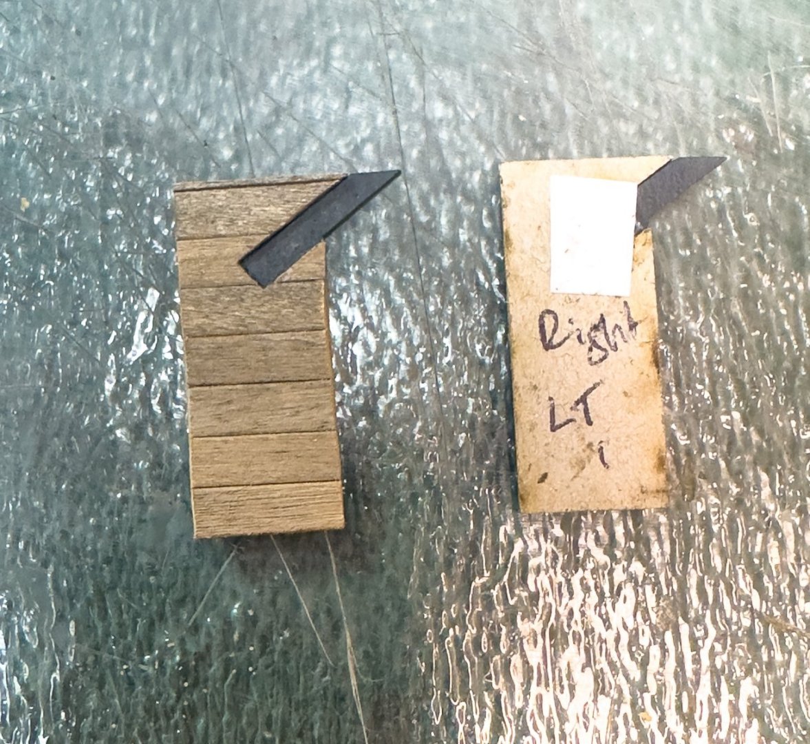
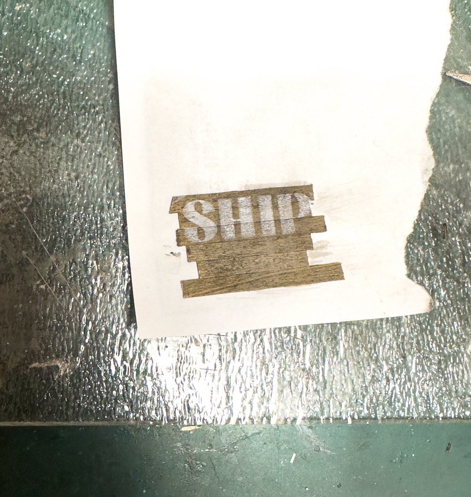
Greetings! Right wall and front stenciled wall now complete. I was not entirely happy with the cardboard awning supplied with the kit, so I decided to replace it with a wooden one using boards from prior ship models. I used the cardboard awning as a template to mark the tar paper lines on the new awning (pencil lines can be seen on the top photo). Marking for the supports and the middle were also marked. One side was stained, the other will be tarped. Final wall: Here is the front wall with the Shipyard stencil. Gluing the walls together is next. The rear and side wall were glued together first, using a metal right angle to keep things lined up. I then glued on the front wall, using graph paper to line up the walls as well as the supplied internal cardboard supports and several square beams (each beam was the same length measured to .01 mm). This makes the structure quite solid. Note in the second photo the missing awning on the rear wall, knocked off during the gluing process. It was easy enough to repair but illustrates how delicate some areas are. I have decided to add some lighting to the diorama. I plan to put some LEDs in all the main buildings of both Foss Landing and the Shipyard, pendant LEDs in the saw shed, goose neck lights over some of the doors and hopefully some streetlights. I even found some small LEDs to simulate a fire in an open oil drum! So, while waiting for the LEDs to arrive for the main building, I decided to build a billboard for the flat roof of the Foss Landing Launch Co. not sure what sign I will put on the billboard but here's what I came up with using some ideas I found online. Jeff
- 68 replies
-
- 12
-
-
-
Greetings! Rear wall construction now complete. No significant issues encountered. As noted in Grant's log, the rafters were a bit long when cut out using the template. It was easy enough to fix though. Regarding the signs, the instructions mention that several copies are supplied on a single sheet. I had just one copy on a template sheet. I made a few copies before working on them. Glad I did as the first try was not acceptable. The awnings were a bit delicate - too much bending of the side pieces or the scalloped edges and they would come off. Each one was stiffened with a light coating of white glue after they were bent in place. First photo shows the larger awning placed using 2 wood spacers to ensure it was centered in the correct position (sharp eyes will see that one spacer was turned the wrong way when I took the photo). Next 2 show the finished rear wall. The left wall was much easier as only the dormer, landing and sawdust collector had to be fixed to the wall. Having the pre-drilled holes to locate the correct position of the dormers made this quite easy. Template seen below aided in construction of the landing. One question I have about the sawdust collector (seen below on the right of the wall). I gather that it is a vacuum that collects sawdust from the shop, however, wouldn't there be a hose or tube at the open end (see red circle below photo) that would lead to a barrel or container to collect the sawdust? Otherwise, sawdust would spray all over the place. Unfortunately, I have not been unable to find any similar contraption on the internet. I am thinking of making some sort of tube that would lead down to an oversized barrel. Any thoughts? Next post I will show the stenciled wall and right wall. Jeff Quote Leave a Comment Home • HO Scale Builds Preview Save Draft
- 68 replies
-
- 12
-
-
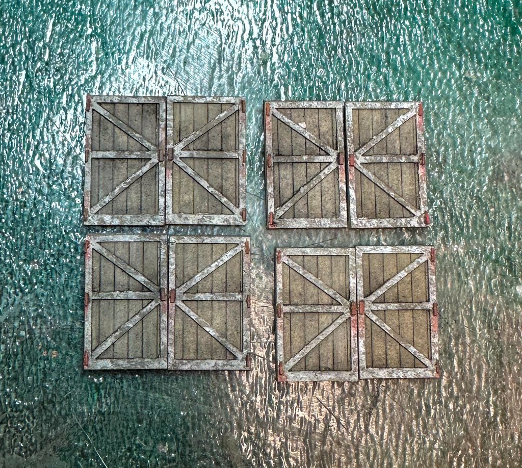
Greetings! Work continues with the dormers. Construction was pretty straight forward. As I've stated before, I won't go into all the details as the log by grant covers this quite well. I did add some beams across the back to add some rigidity to the structure. The flashing on the right wall dormer sides is to be removed, painted then glued back, flush with the back of the wall. To give this delicate piece a larger surface for the glue, I first glued a piece of paper to the back of the side wall then glued the flashing into its space. I also noticed that when the dormers are placed onto the left and rear walls, the lower part of the scribed inner wall is visible. I did not like this look so it was covered with the same planks used for the walls. I think this looks better. BTW, the white of the window frames still looks a bit stark as I have not yet toned them down with some grey chalk. Completing the doors and windows that go on the walls was a breeze thanks to the kit's construction methods. Here is a photo of the freight doors. And before applying the "SHIPYARD" stencil, I did a practice run on some scrap wood. here is the result. And finally, my thoughts on adding nail holes to simulate where the boards are nailed to the underlying beams, which is an option given during construction. I've reading many of the comments on the SW forum, I decided to place small "holes" only where 2 boards butt. In researching what kind of nails are used on wood siding, I came up with a nail size of 8d. This has a nail head size of 9/32 inch. At HO scale, converting to metric, this is ~ 0.08 mm, which is the approximate diameter of a human hair. The smallest nail indent I could make, even with the finest sewing needle, is 0.2-0.3 mm (this translates to a 1 inch nail head). I did some nail holes on the Foss landing building and looking at them now, they are barely visible after the building has been finished, and only from very close up. And if we are looking at the model at a distance of 1 foot, this would translate to 87 feet - how visible would nail holes be at that distance. So with all this in mind, I decided to forgo the nail hole rows. Similar discussions can be found on this forum on the use of treenails on deck and hull planking, especially at scales less than 1:48. after a few more steps the walls will be glued together and the building will begin to take shape. jeff
- 68 replies
-
- 12
-
-
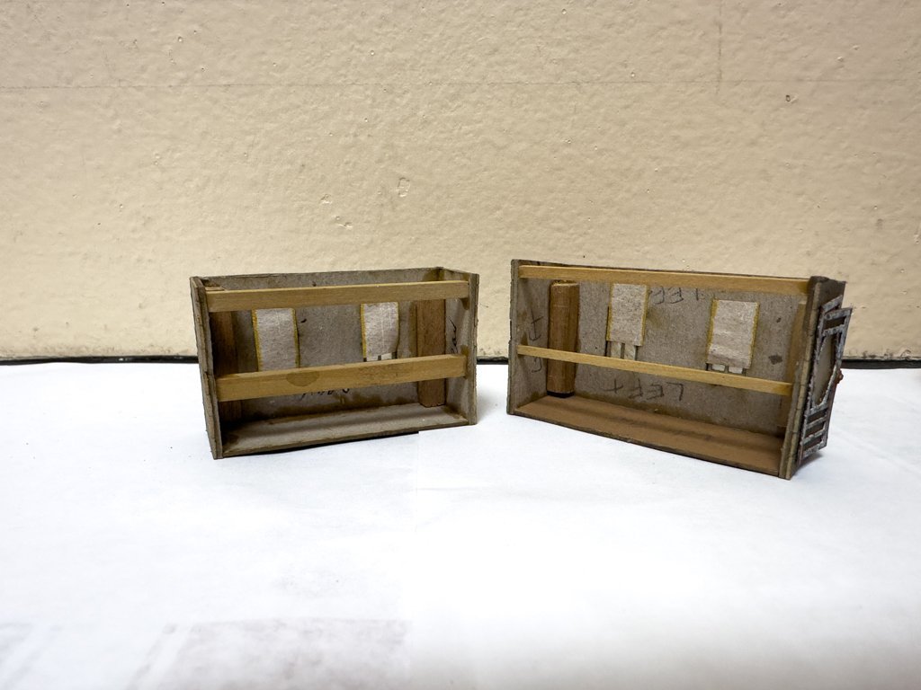
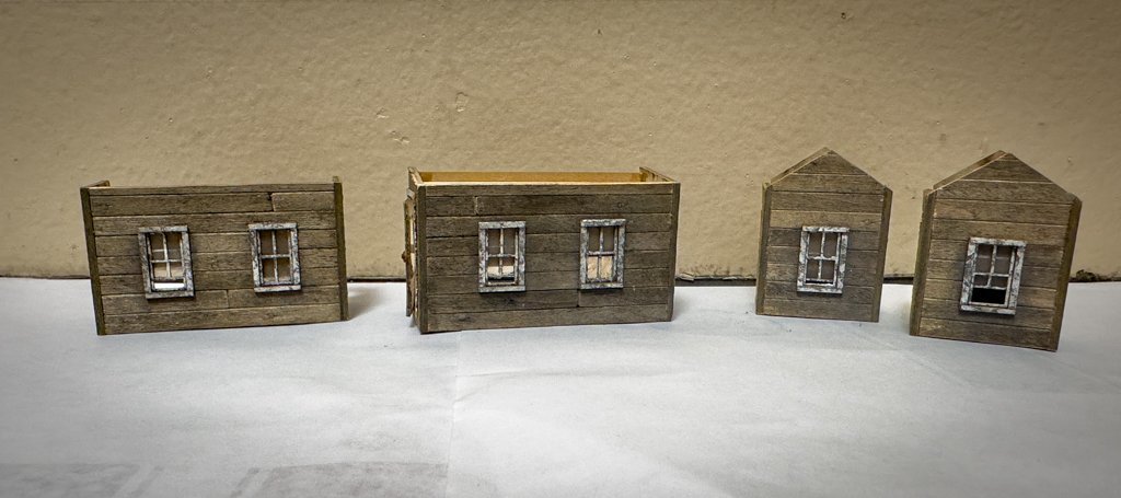
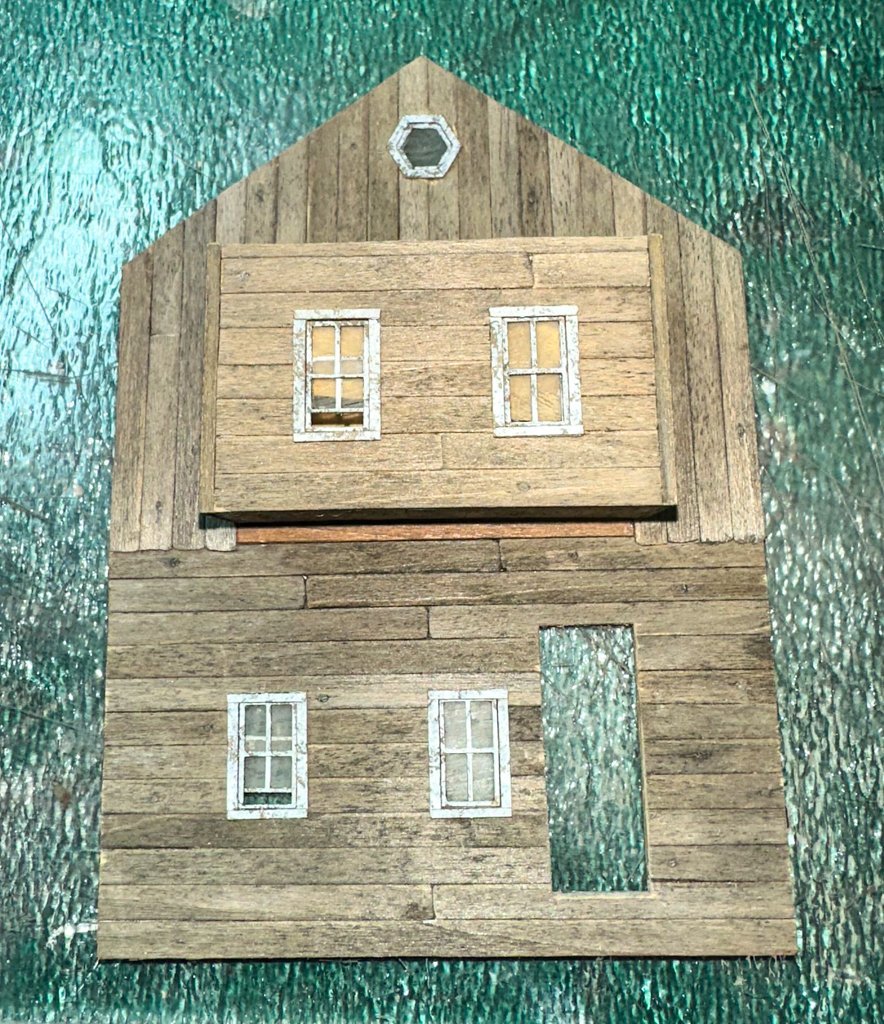
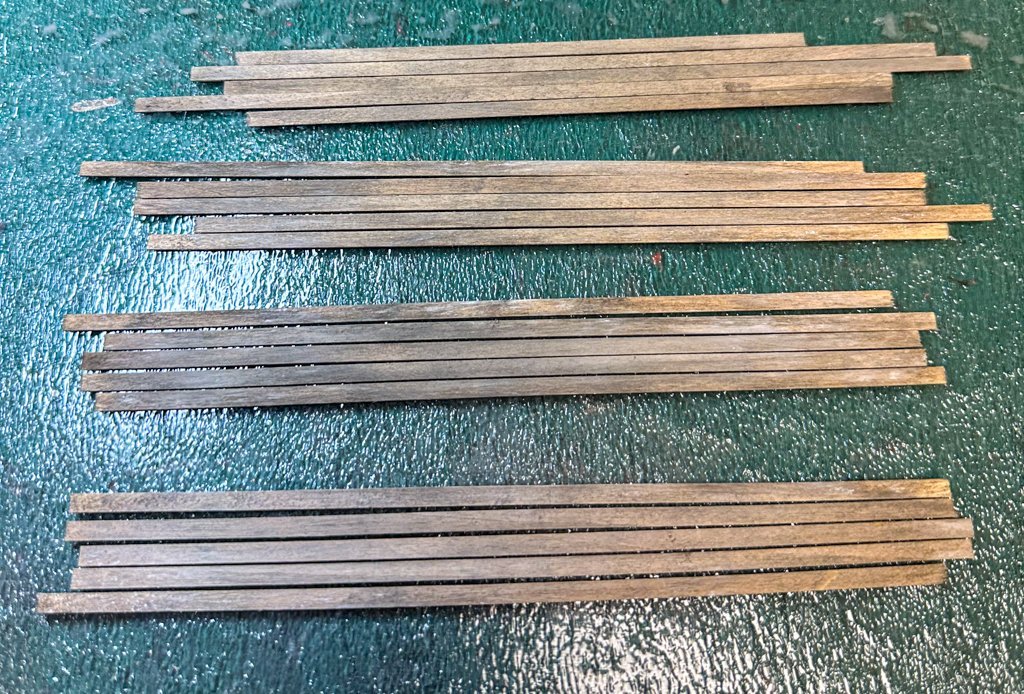
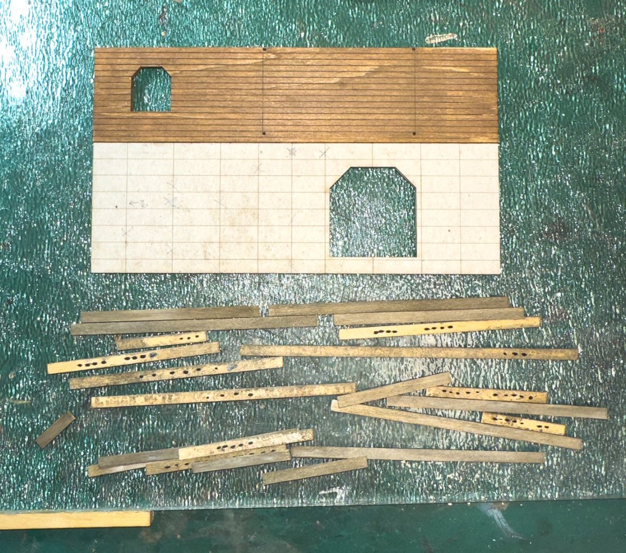
Greetings. now on to The Shipyard at Foss Landing. A fellow member, gjdale has created a build log on this kit so I'll not spend time replicating what he has done. His build log is an excellent reference for anyone wishing to tackle this kit. Unlike the Foss landing buildings, the structures of the Shipyard are built up from wood strips. Each strip has to be stained, weathers and glued in place. The Sierra West forum has some great tutorials on how to do this. The strips are then glued to a thick cardboard backing to create the walls Here's a photo of some of the main building wood strips. Chalk (Rembrandt 408.3) and alcohol applied after some texture using a wire brush. I plan to do some of the more advanced wood work as described such as edge sanding, splits, knots. bottom of boards wear and tear, etc.) as I place the boards on the walls. This will also keep things from getting too repetitive. With the initial wood chalked, it's time to start the walls of the main building. Quite a difference in construction compared to Foss Landing. First a little background on how I laid the boards. First consideration - how long should each plank be? A single plank across the full face of the left or right walls would be are 156 mm across, equivalent to 44 ft at full scale - much too long for a single board. With a little research, I found that typical lengths for wood housing planks are 12 ft (HO 42 mm). Longer lengths offered would be 16 ft (56 mm), 20 ft (70 mm), 25 ft (87 mm). Not sure if this would translate to a building such as this but I decided to go with it. I felt that 42 mm was a bit small so the longer lengths were used. Any space on the wall that was at scale 10-12 ft or less would not have any butt joints in my opinion. With this in mind, here is the left wall with the planks laid out but not glued. Per my previous post, full length planks were initially treated with chalk. Once cut to size, they were finished in a manner described using tutorials on the Sierra West forum. Damage to boards such as splits, cracks, etc. were kept to a minimum. To quote the instructions, "this is a working shipyard and repairs would be made quickly..." Below, the boards have been cut to size, weathered and laid out on the wall template. Notice the solitary plank sitting on the scribed area. It has a visible grain that does not take chalk or AI stain very well. Several of the full-length boards have areas such as this so one has to be vigilant that none find their way onto the wall. It was interesting to note that the visibility depends on the orientation of the board as well. So once the boards are laid out, each was marked on the reverse side with a sharpie. The number on dots indicate which row it goes to. For the second floor boards, using my rule from above, no butt joints were added as the length was 38 mm (full scale 10.8 ft). I also added some chips and gouges to a few of these boards, figuring they would end up a bit more weathered than the first floor, but nothing too severe. Final result: Dormers are next. Jeff

- 68 replies
-
- 11
-
-
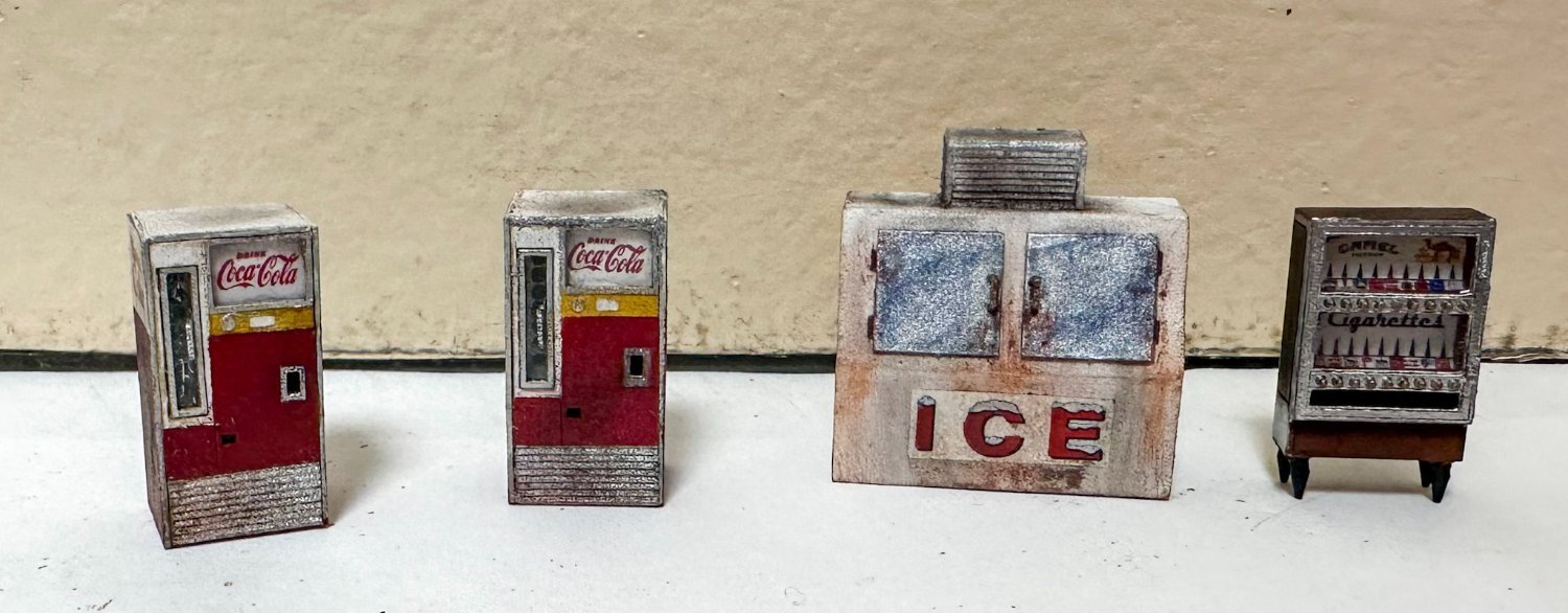
Greetings, Here we are at the last part of Foss Landing, the barrels and oil drums and rowboats. The rowboats will be upside down scattered around the diorama so no need for the interior detail work. I have a few larger HO scale rowboats that will be more complete Below is the small scale. I found a photo of a scale face and shrunk it down (a lot!) and glued it to the front of the scale. This completes the structures and castings of Foss Landing. Constructions will soon start on The Shipyard at Foss Landing. Looking forward to this - a larger, more detailed building. Shout-out to to folks on the Sierra West forum for their wonderful tutorials. Jeff
- 68 replies
-
- 12
-
-
-
xodar461 reacted to a post in a topic:
Revenge 1577 by xodar461 - FINISHED - Amati - Scale 1:64
-
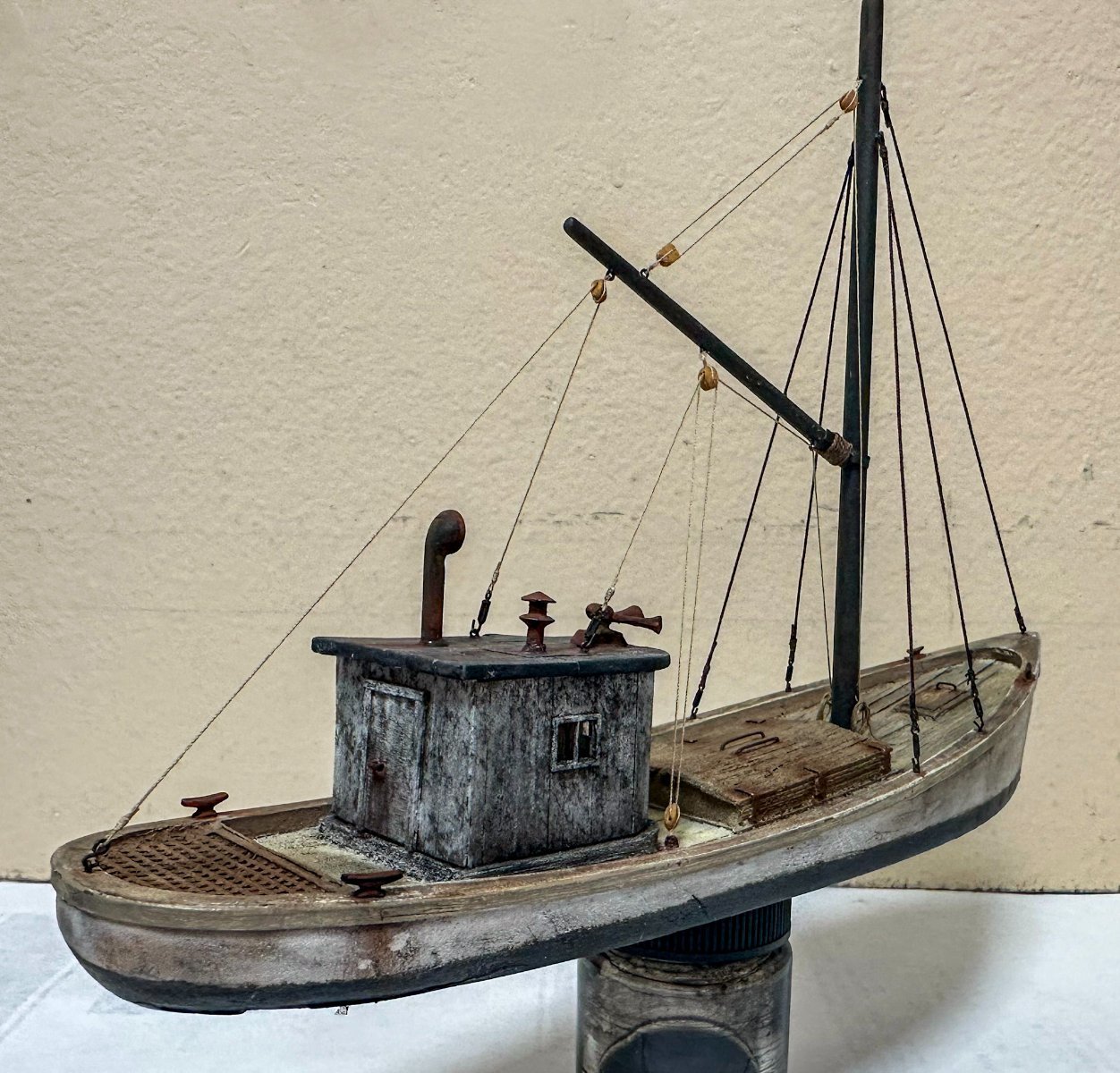
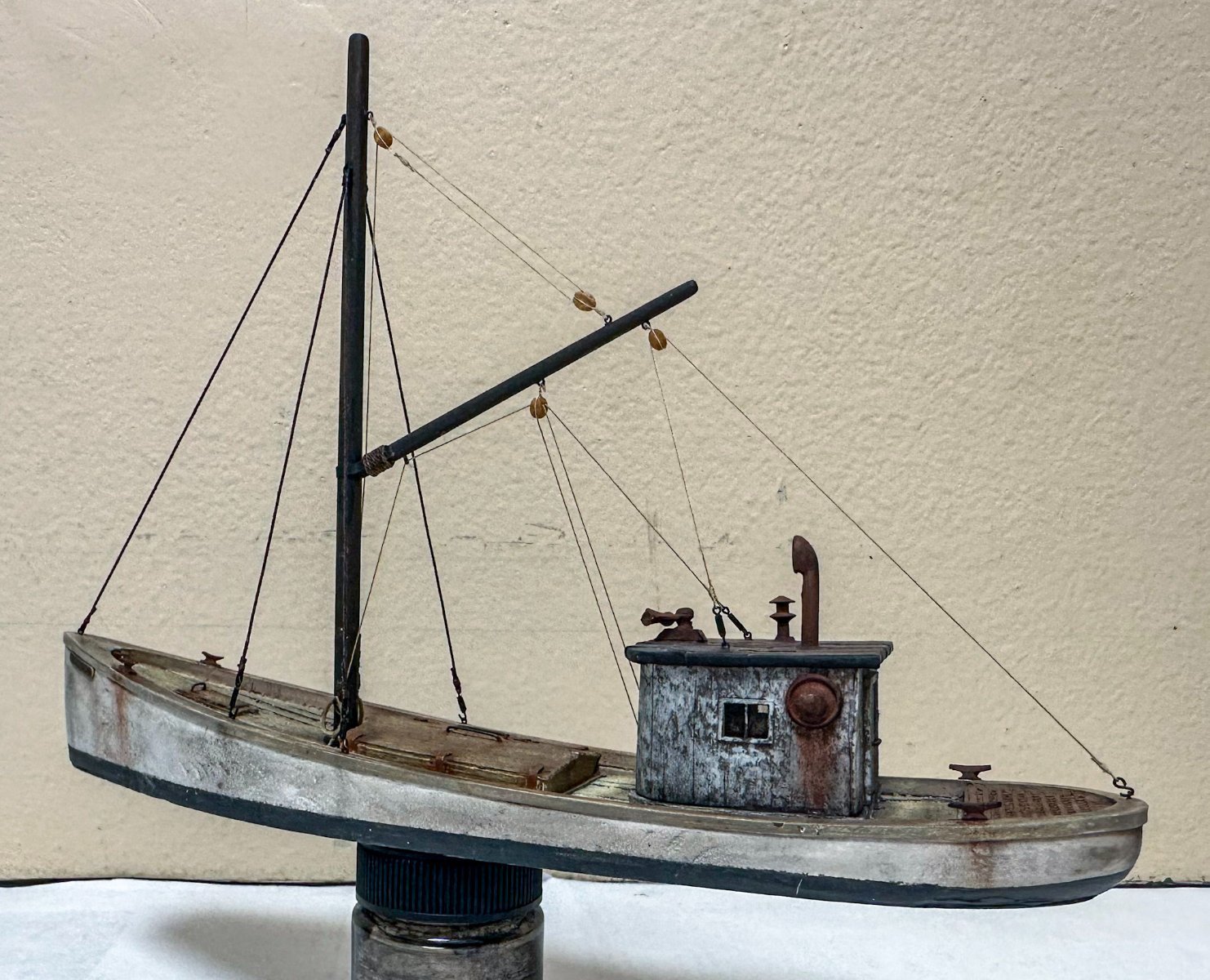
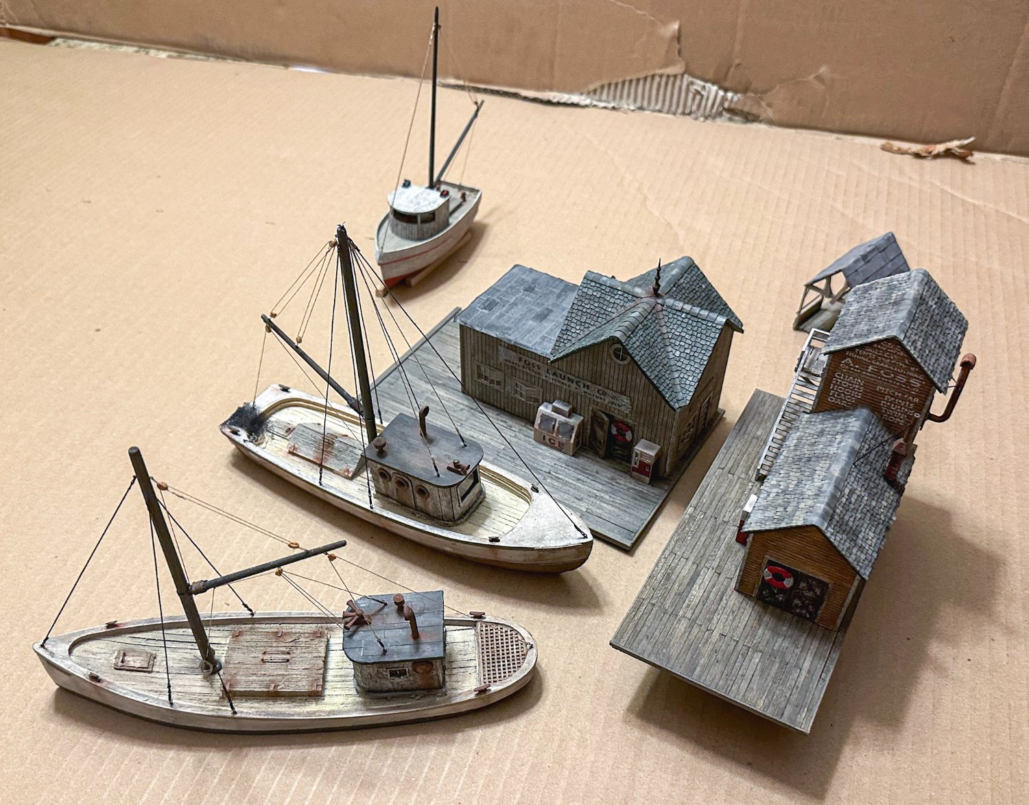
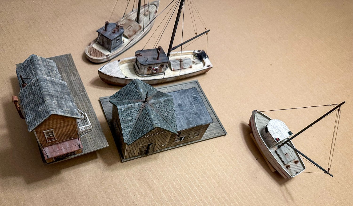
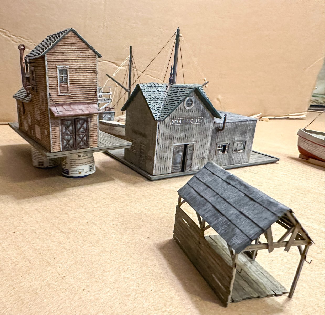
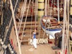
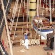
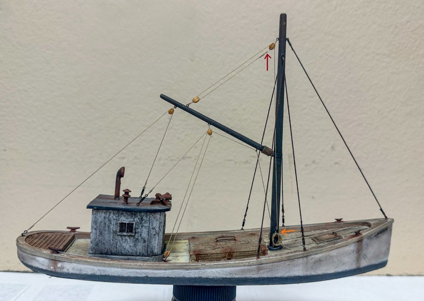
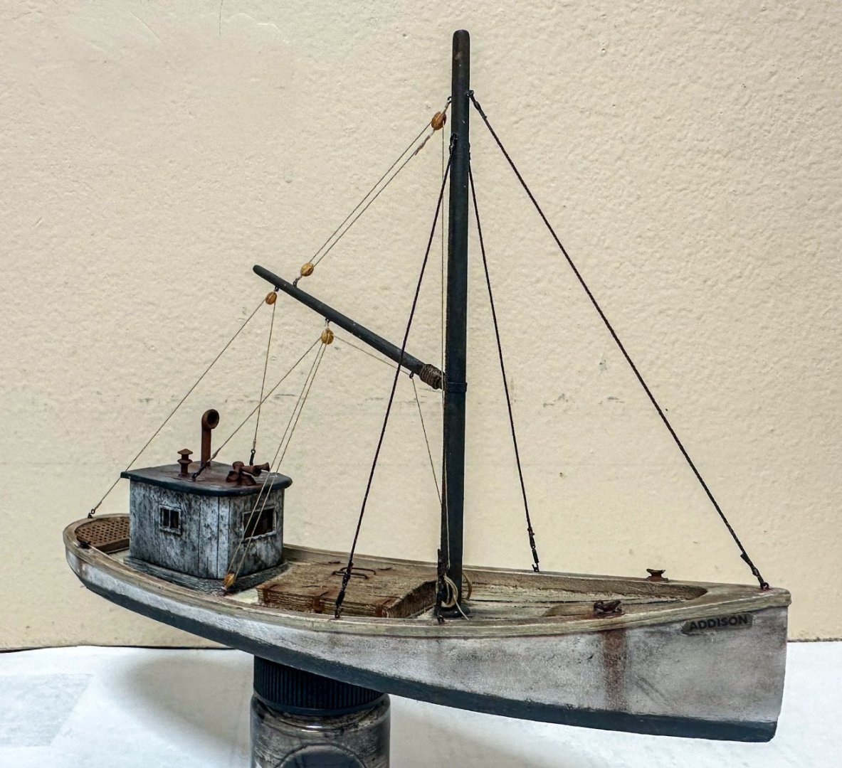
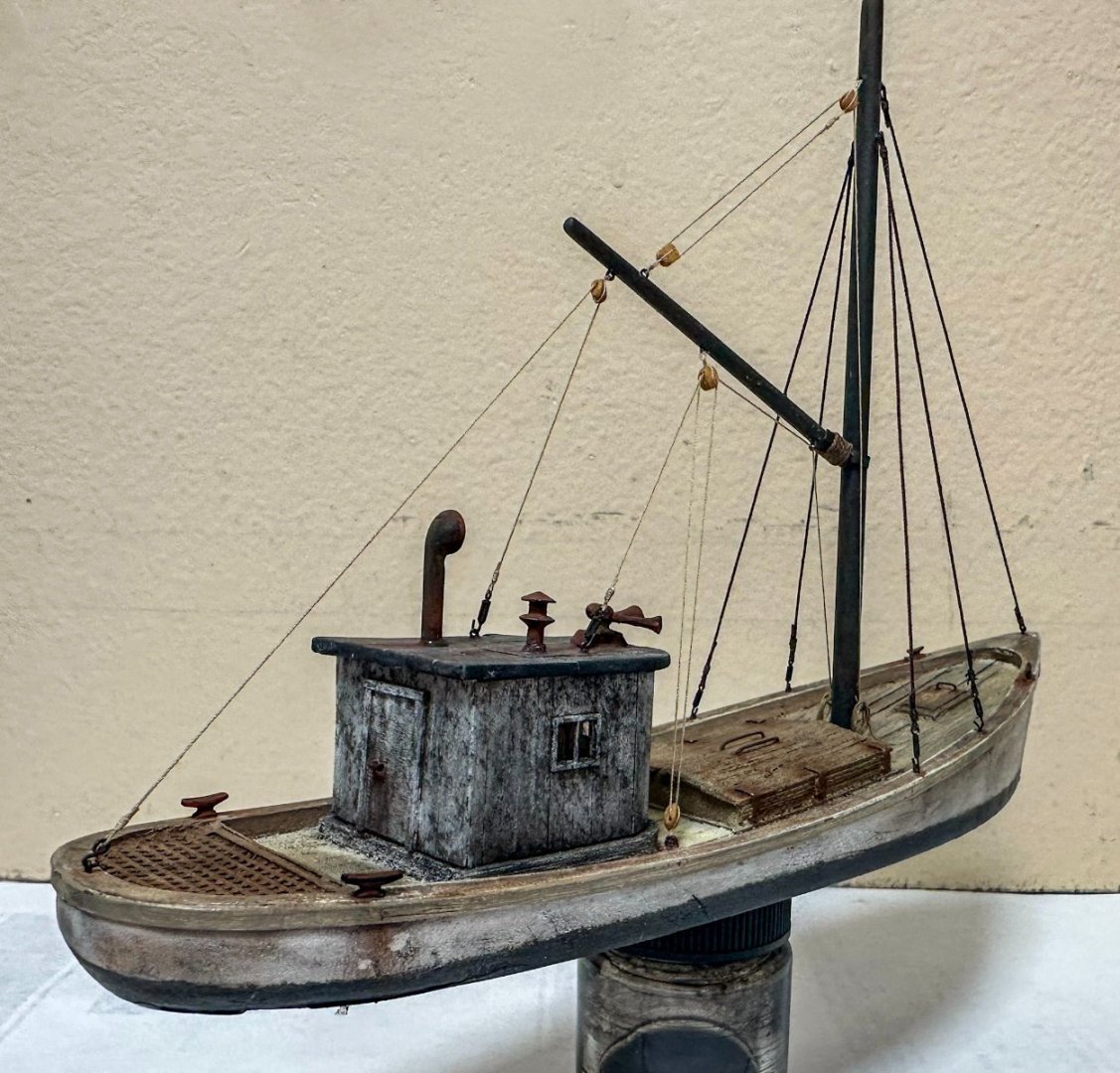
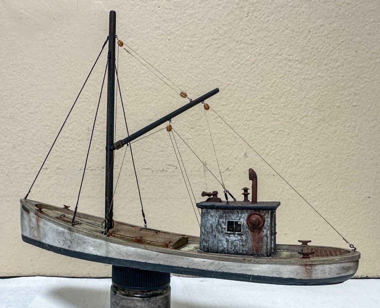
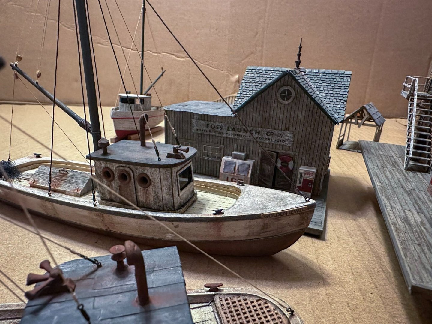
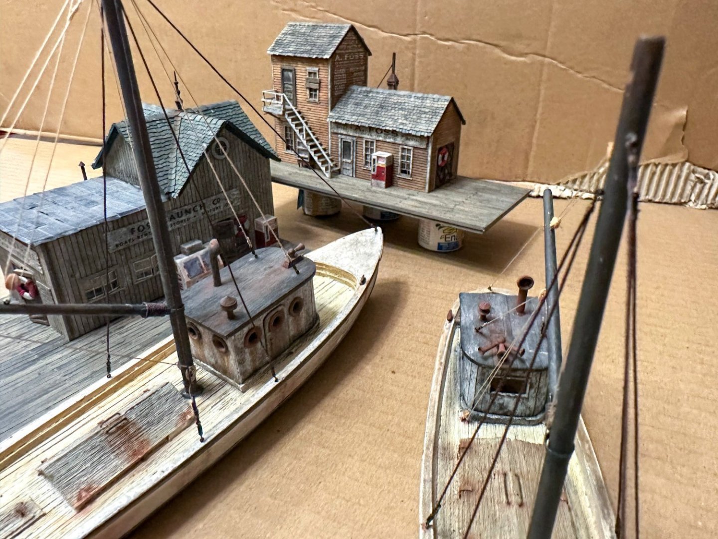
Greetings! It has been a while since my last post but work proceeds on Foss Landing. I have completed the Addison and here are a few photos. Construction is quite similar to the Jewel so there is no need to repeat. As with the Jewel, I chose to rig with scale blocks and rope, using turnbuckles for the standing rigging. The arrows on the photo below were for a brief tutorial on rigging that can be found on the Sierra West forum. I will probably add some more details like netting, spare rope and barrels at a later time. This completes the structures of Foss Landing. Here are some photos of them all laid out like in the diorama. And here is a photo of some HO scale add-ons that can be seen in the photos above. Next up: finishing the barrels, oil drums and trash cans, then onto the Shipyard. Jeff


- 68 replies
-
- 18
-
-
-
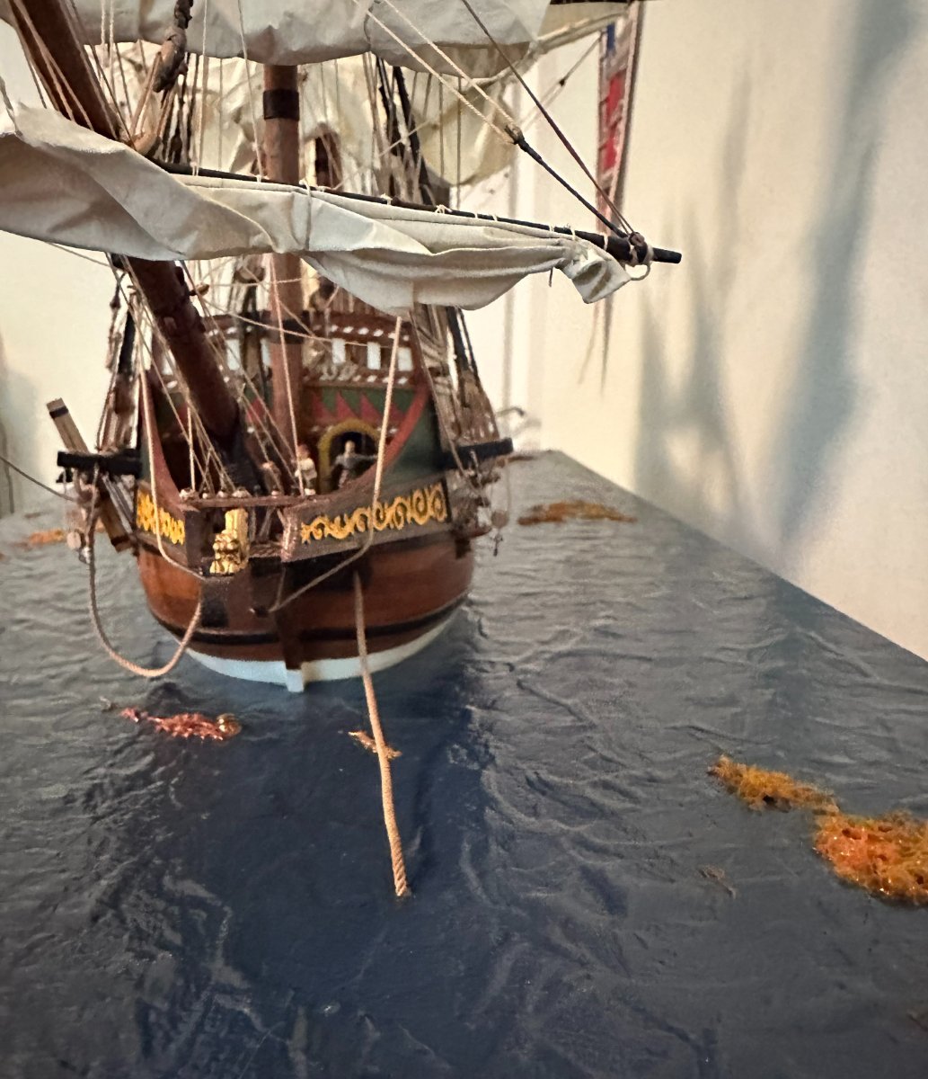
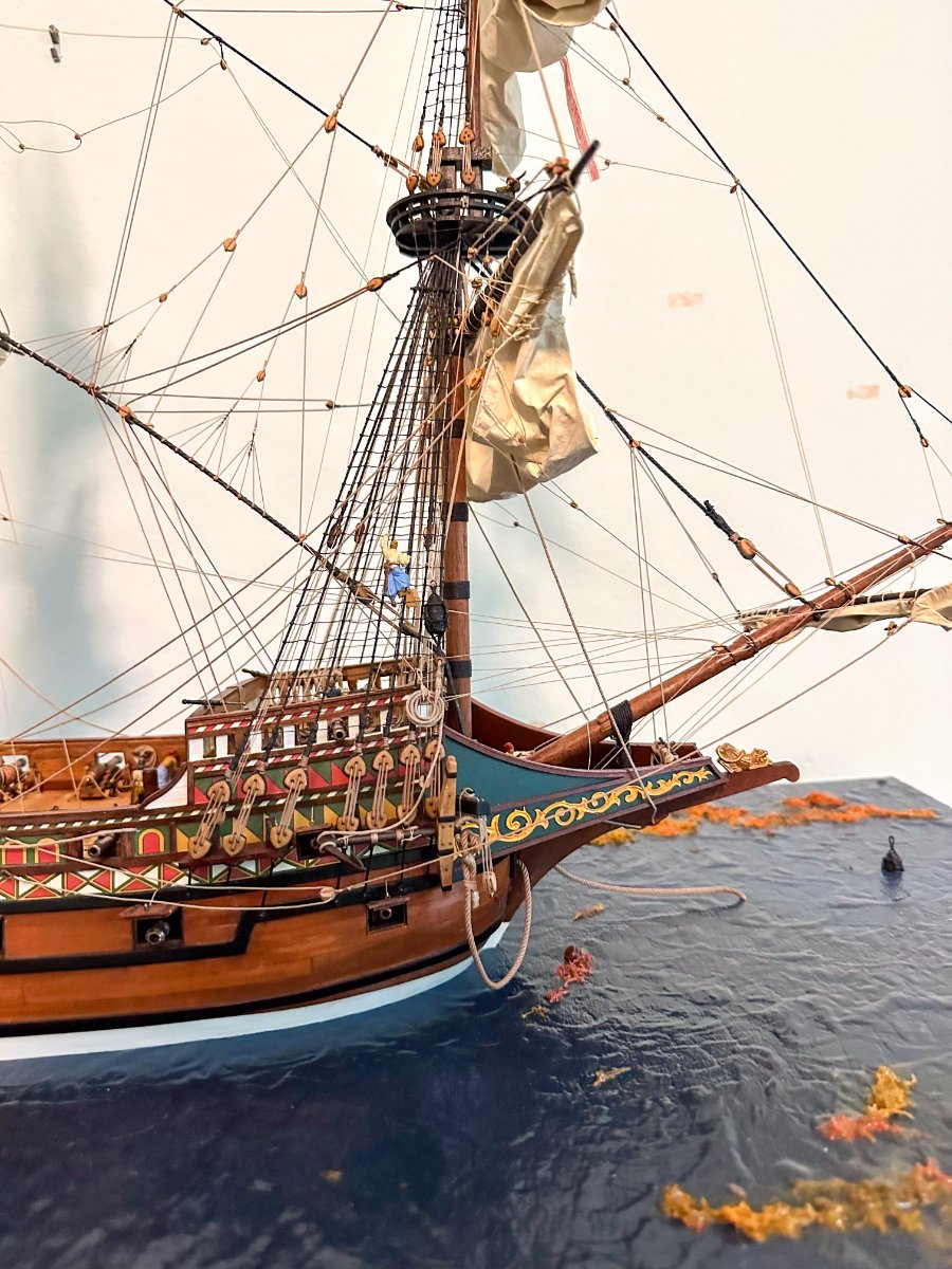
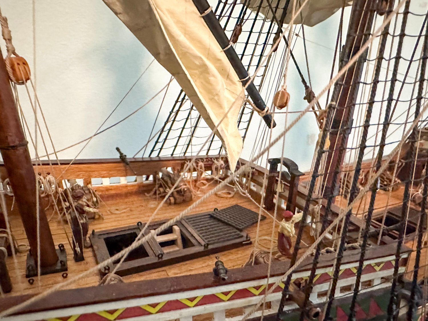
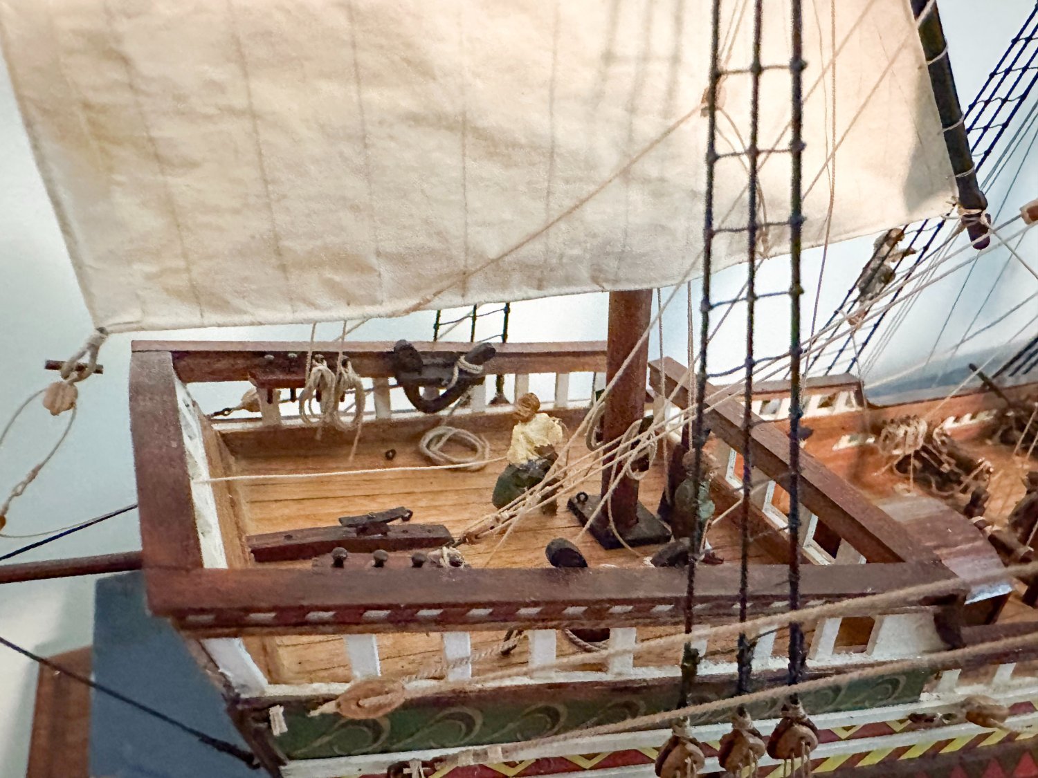
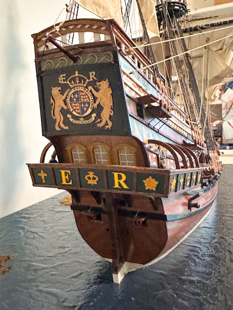
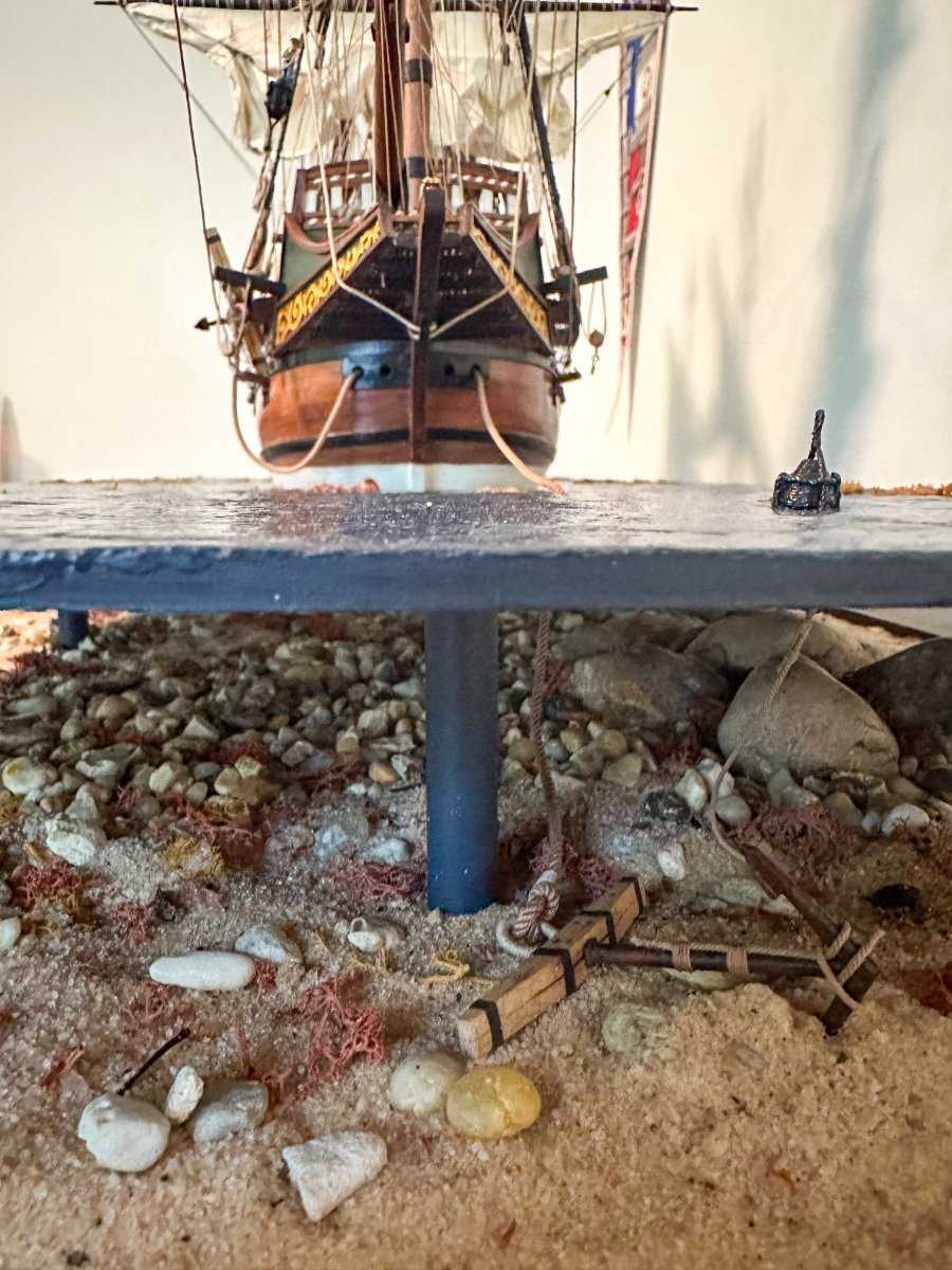
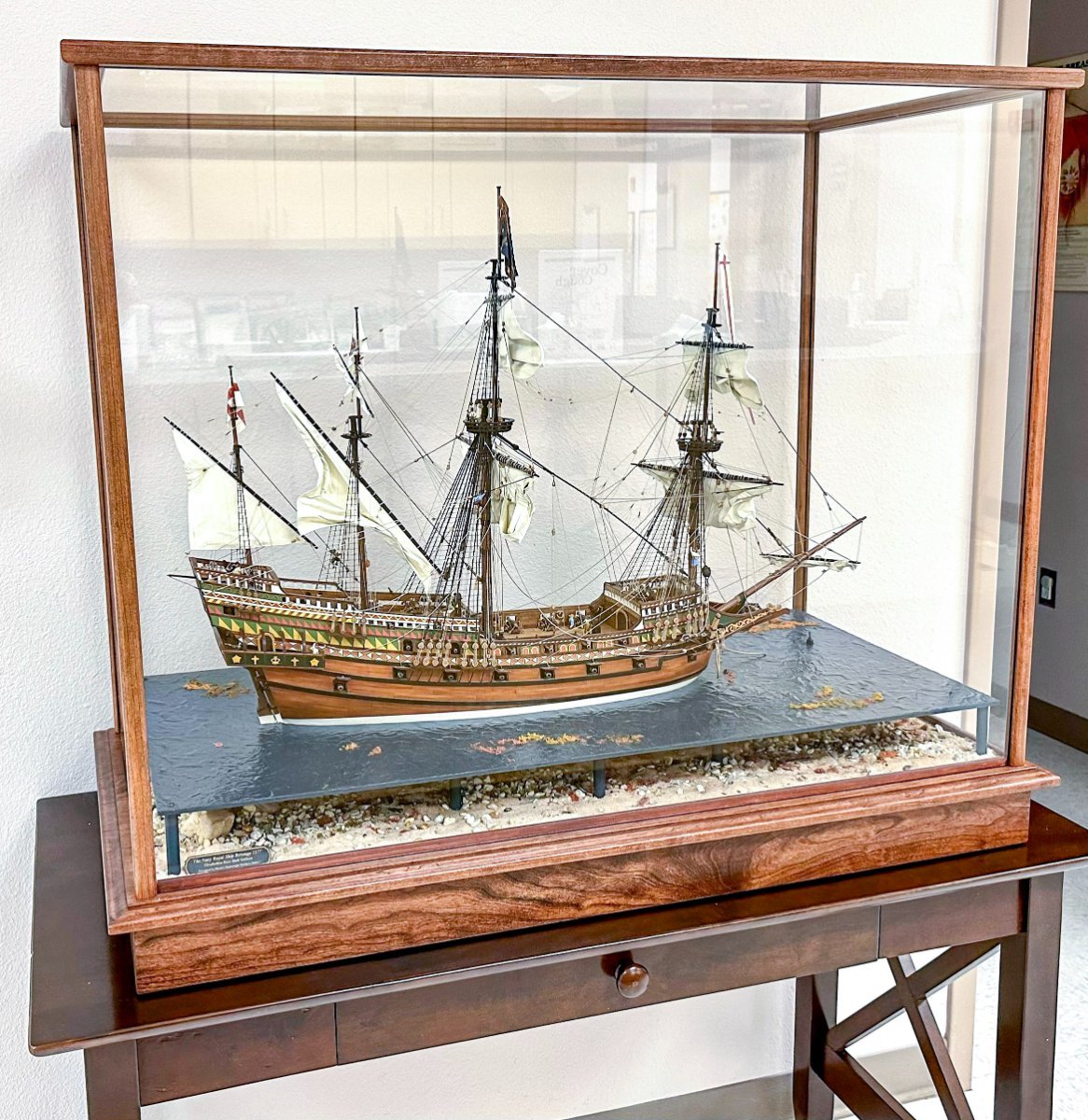
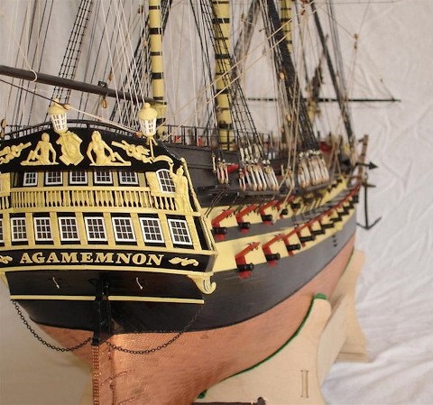
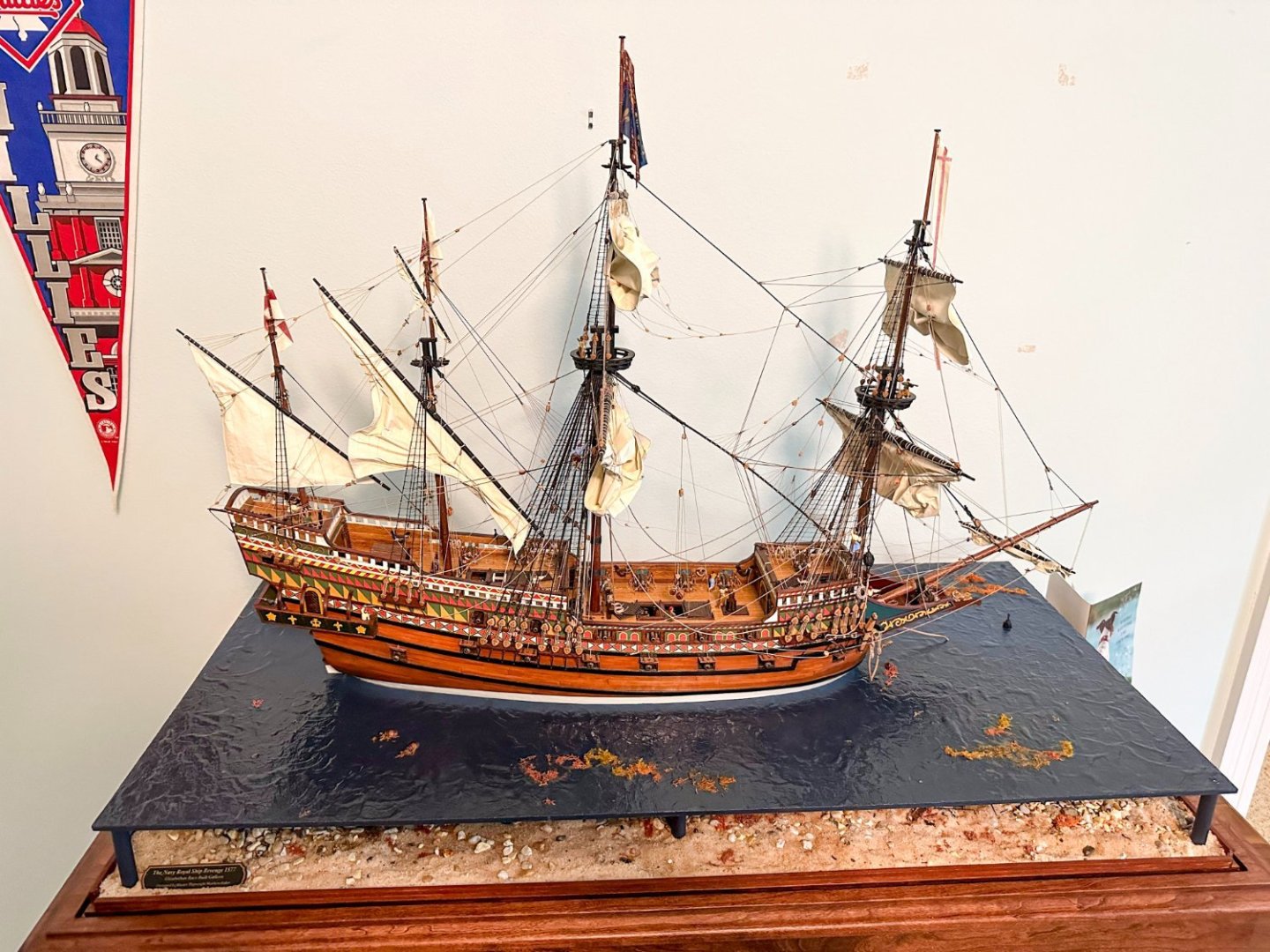
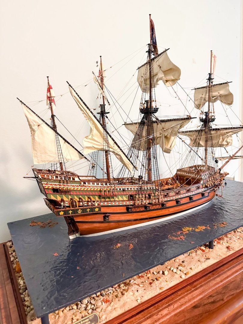
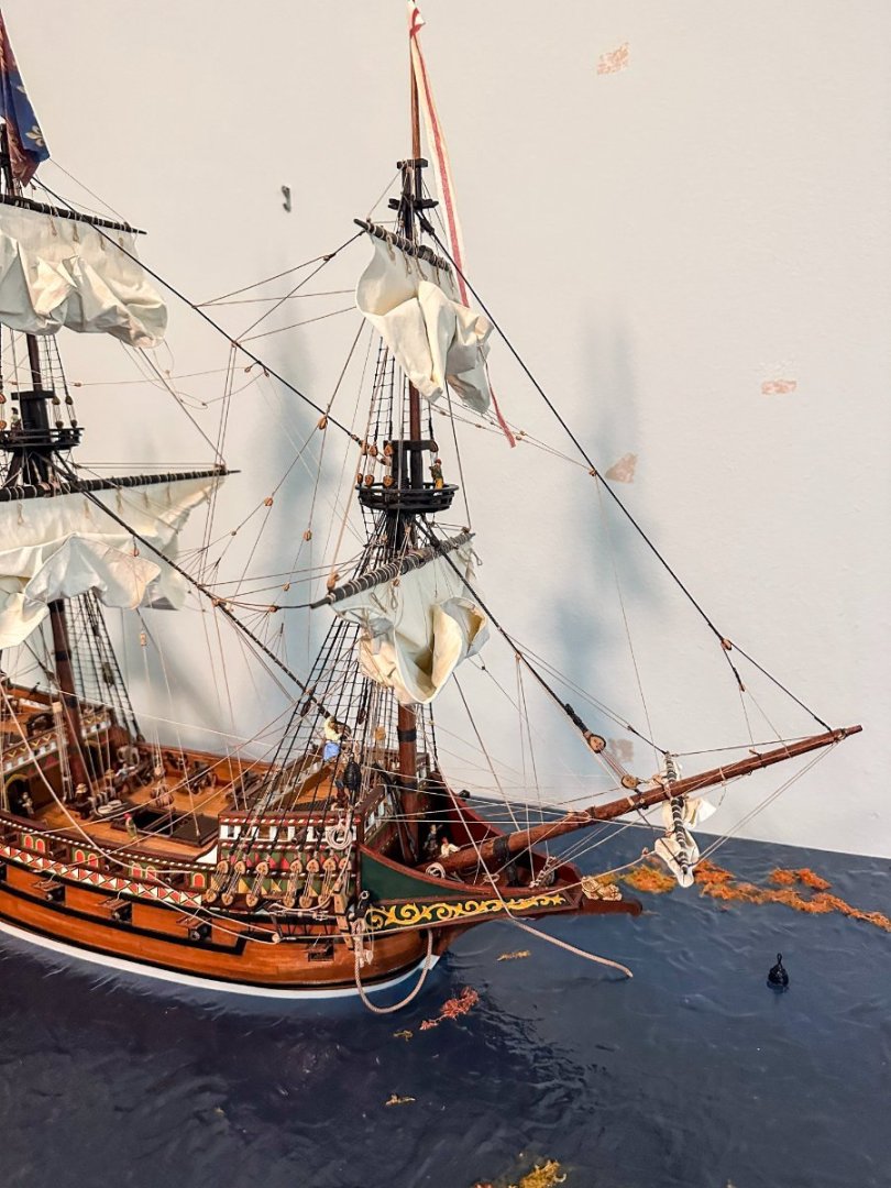
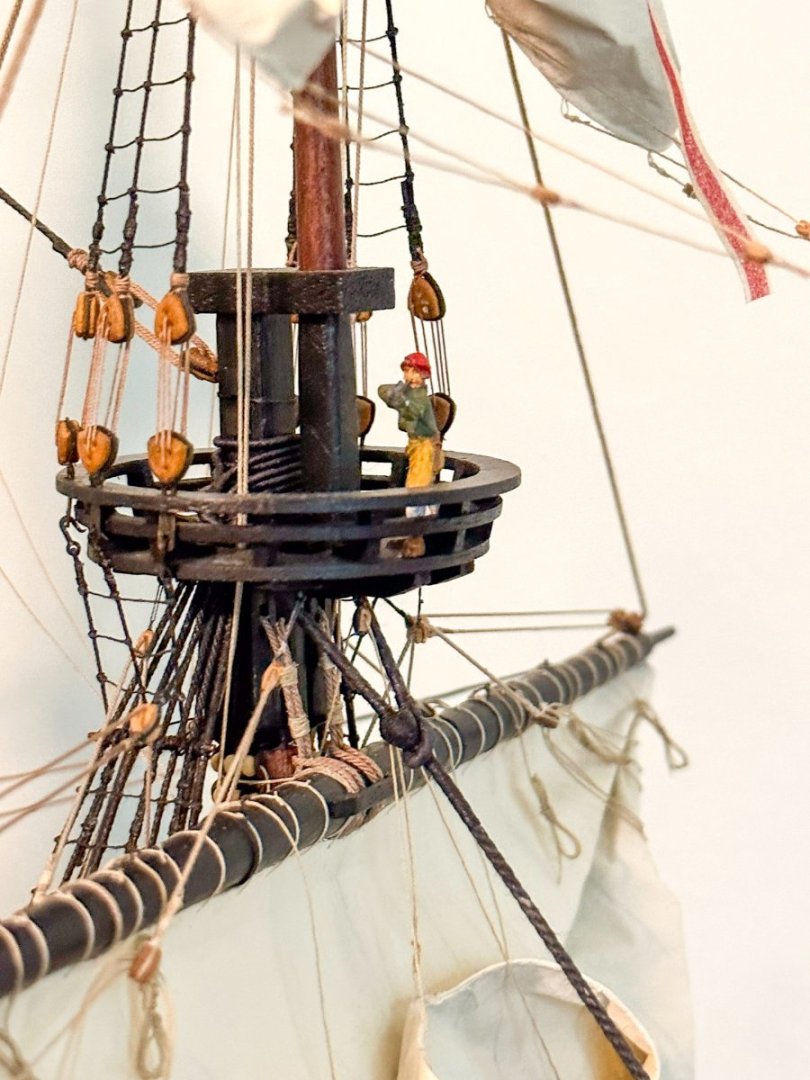
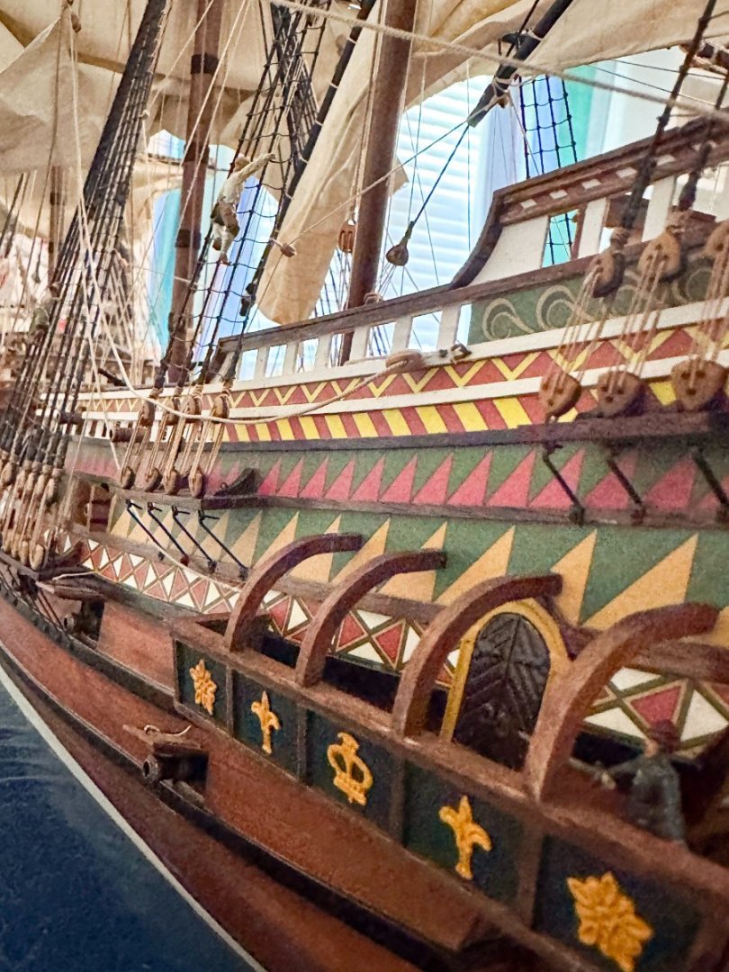
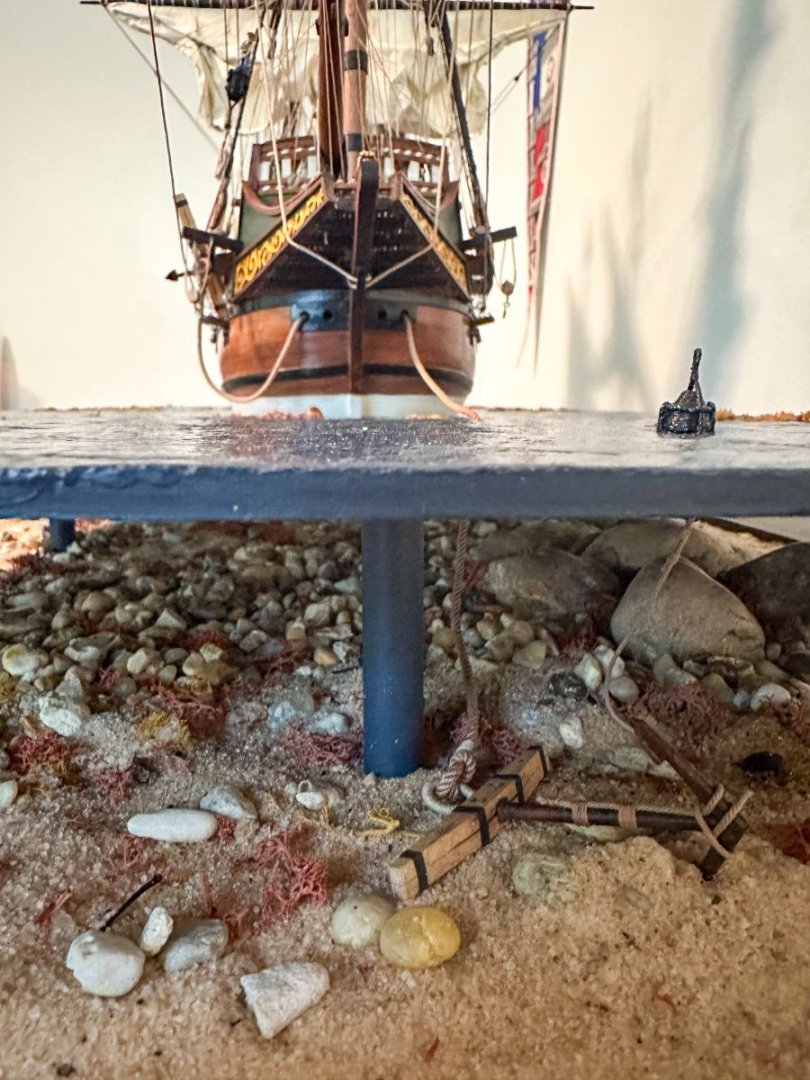
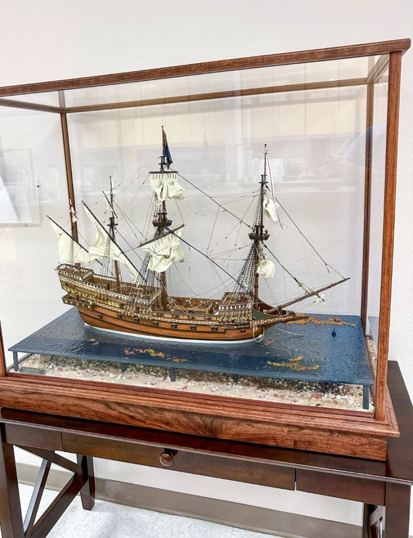
Greetings! Seems I forgot to do my last post for this fine kit. Well, here it is. Several pics of the completed ship and 2 with it in the case. The ship was 4 cm too tall to fit in the back of my SUV so I had to rent a panel truck to get it to my office. Thanks for following along with my build log and be sure to check out "Foss Landing and the Shipyard at Foss Landing" in the Non-ship build section of shore leave. Jeff


- 158 replies
-
- 10
-
-