DocBlake
-
Posts
1,811 -
Joined
-
Last visited
Content Type
Profiles
Forums
Gallery
Events
Everything posted by DocBlake
-
 Does anyone have any information on how the mortar was rigged? There is nothing in Jeff's plans and nothing in Goodwin's book to guide the rigging. Obviously it involved block and tackle attached to the mortar bed and the walls of the mortar pit, but how many, and where were they placed?
 -
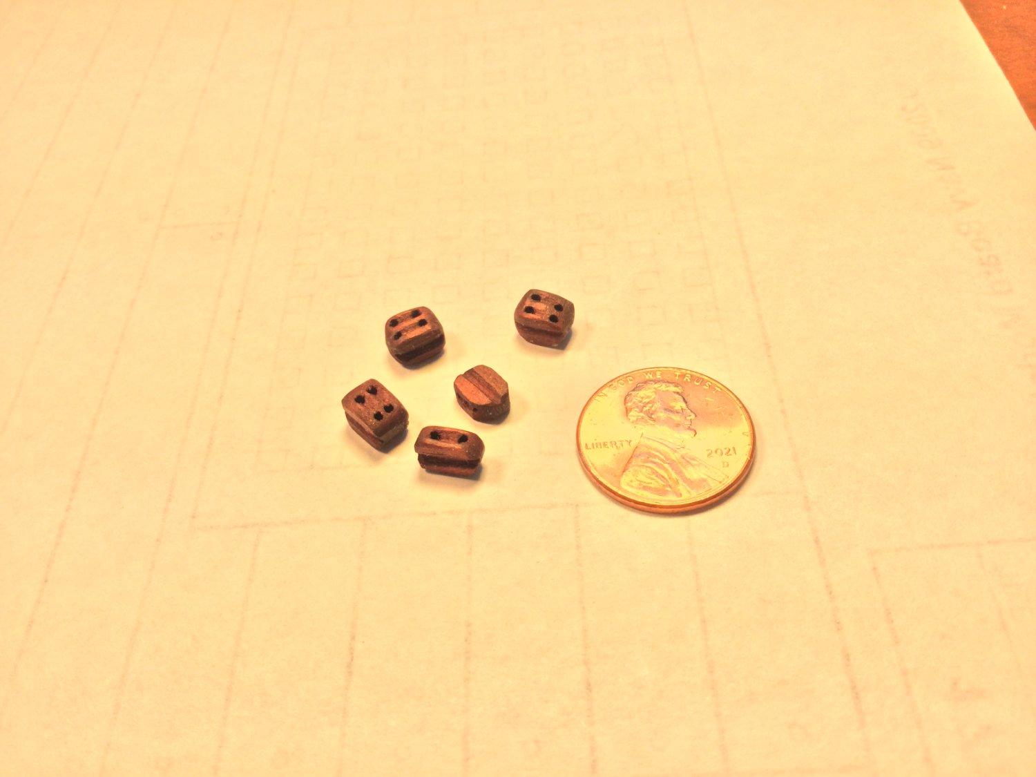
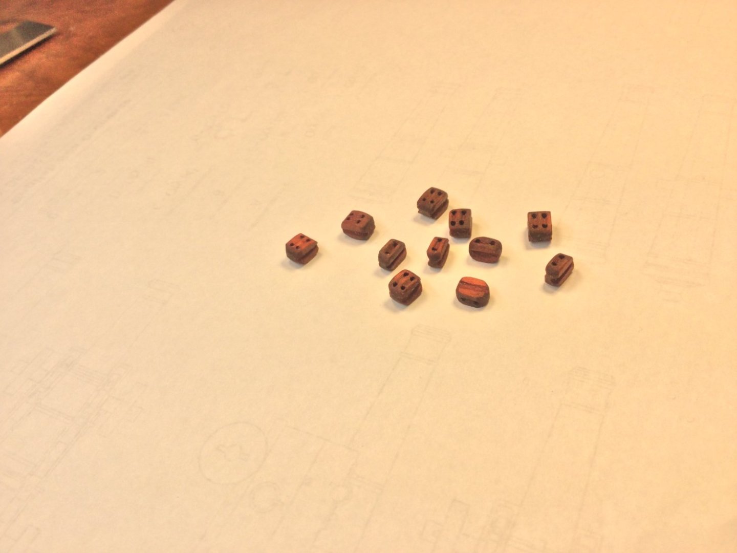
Single and double blocks made from scratch. The wood is swiss pear finished with boiled linseed oil. The single blocks are 1/4" long (8" in scale) and 3/16" wide with a 1/8" thickness. The double blocks are 1/4" long, 3/16" wide and 3/16" thick. The sheave holes are drilled with a #60 drill to accommodate .025" diameter gun tackle line. The penny gives size perspective.

- 143 replies
-
- 12
-

-
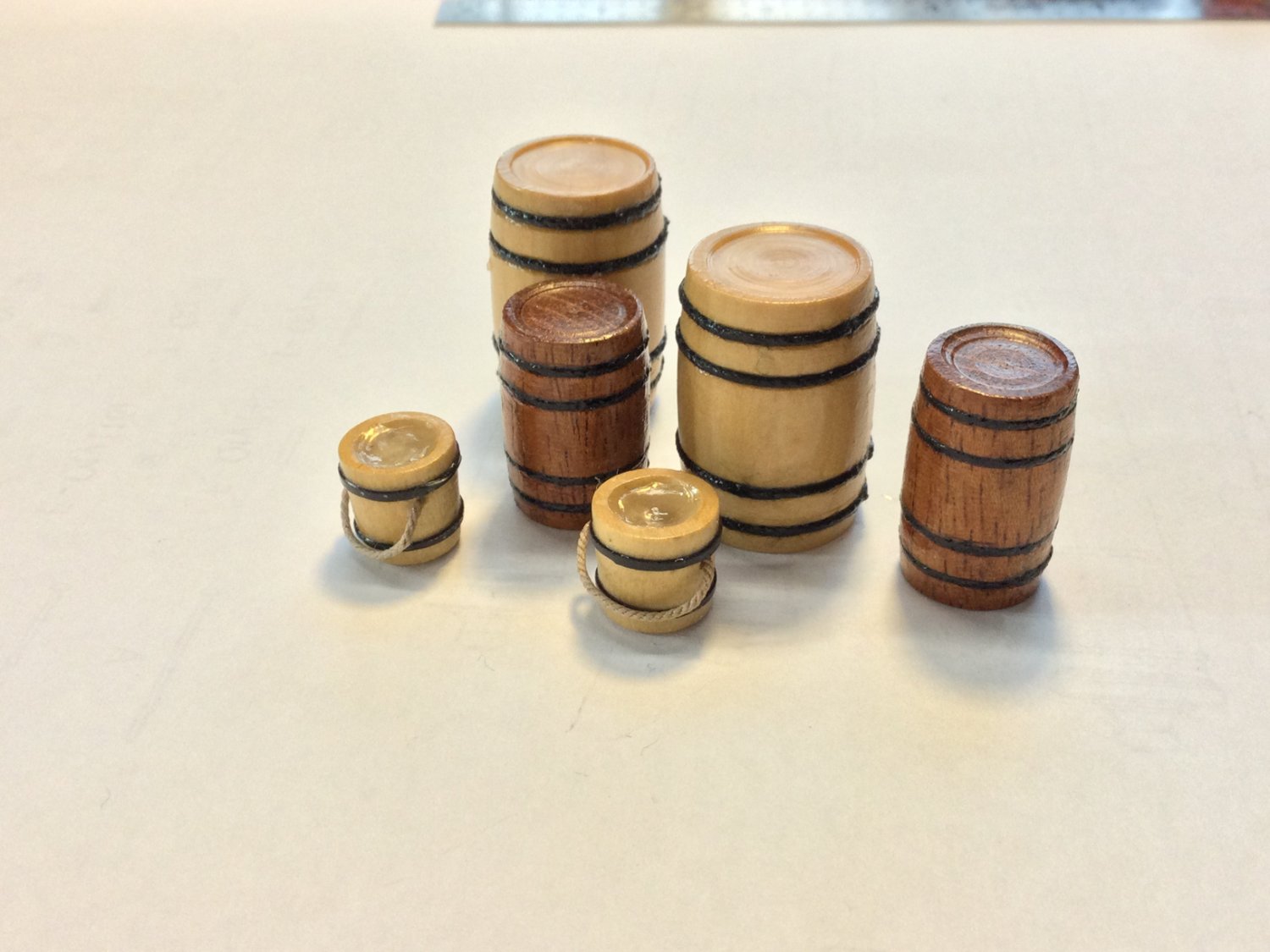
Thanks Pat and everyone for the "likes"! I turned some barrels and buckets awhile ago to fill out the detail for the two battle stations.

-
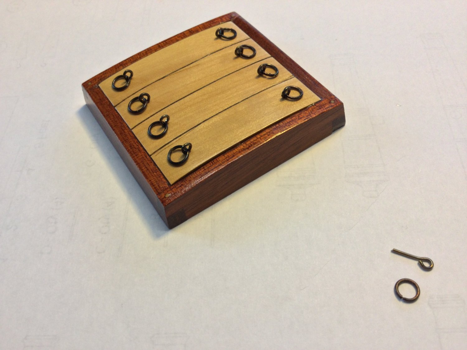
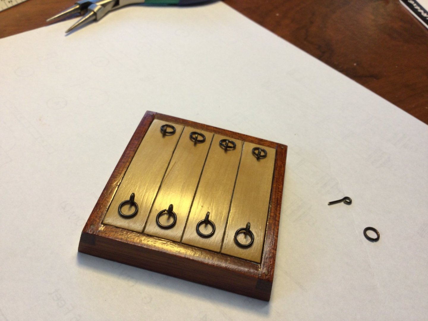
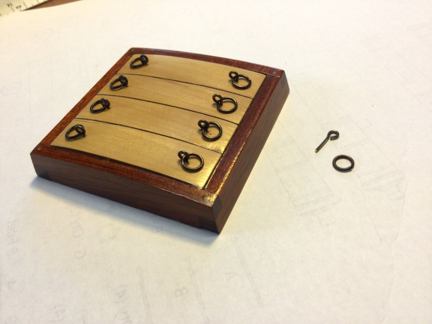
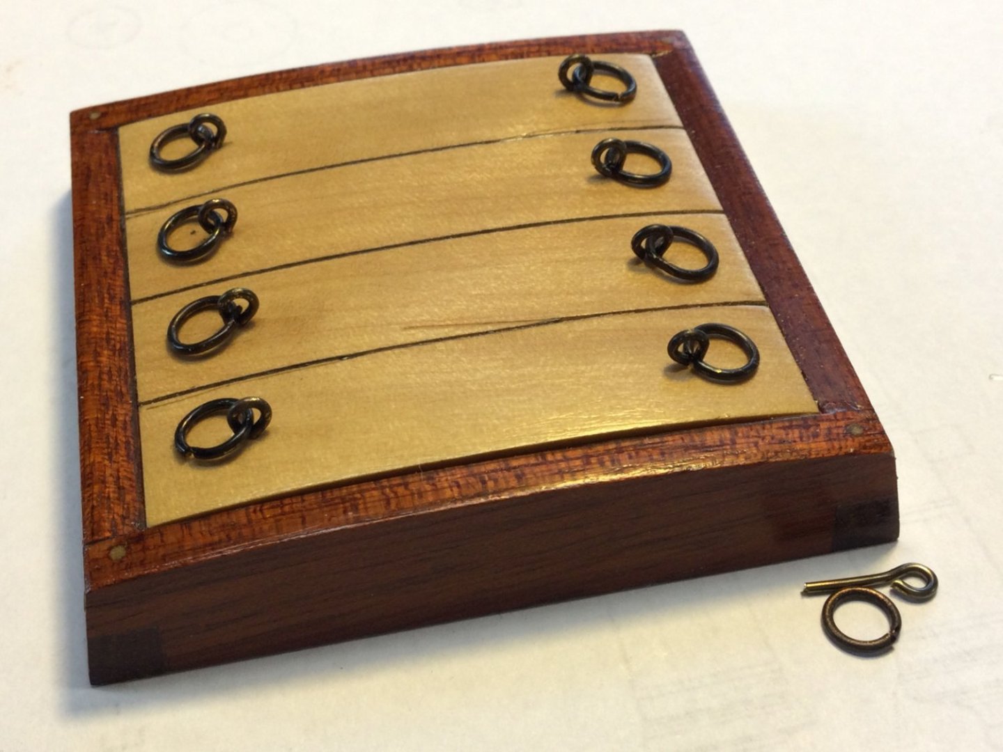
Thanks, Pat. Those are holes drilled in the trucks and darkened with pencil lead! I finished up the main hatch by adding the eyebolts and rings to the covering boards. Both are made of .032" diameter brass rod, blackened with Brass Black. The eyebolts are made with a jewelry making tool known as a "looper". The rings are annealed brass rod, using a torch, which is blackened, then wrapped around an appropriate sized drill bit and cut free with a wire cutter.

-
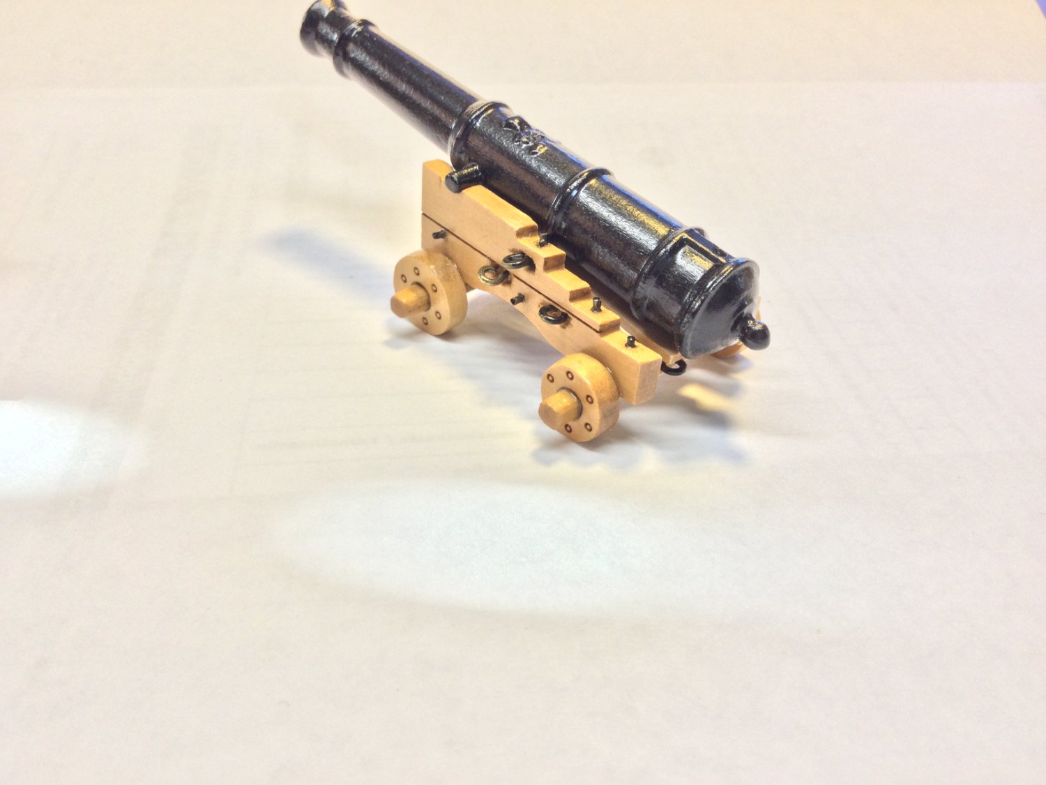
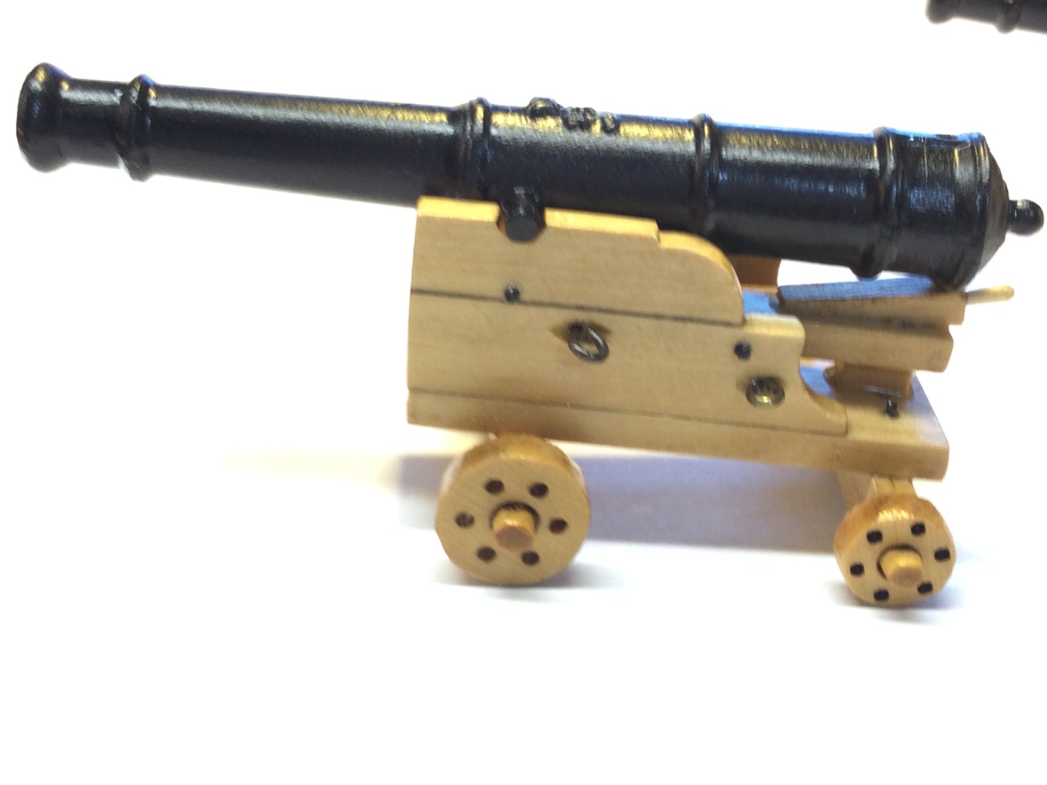
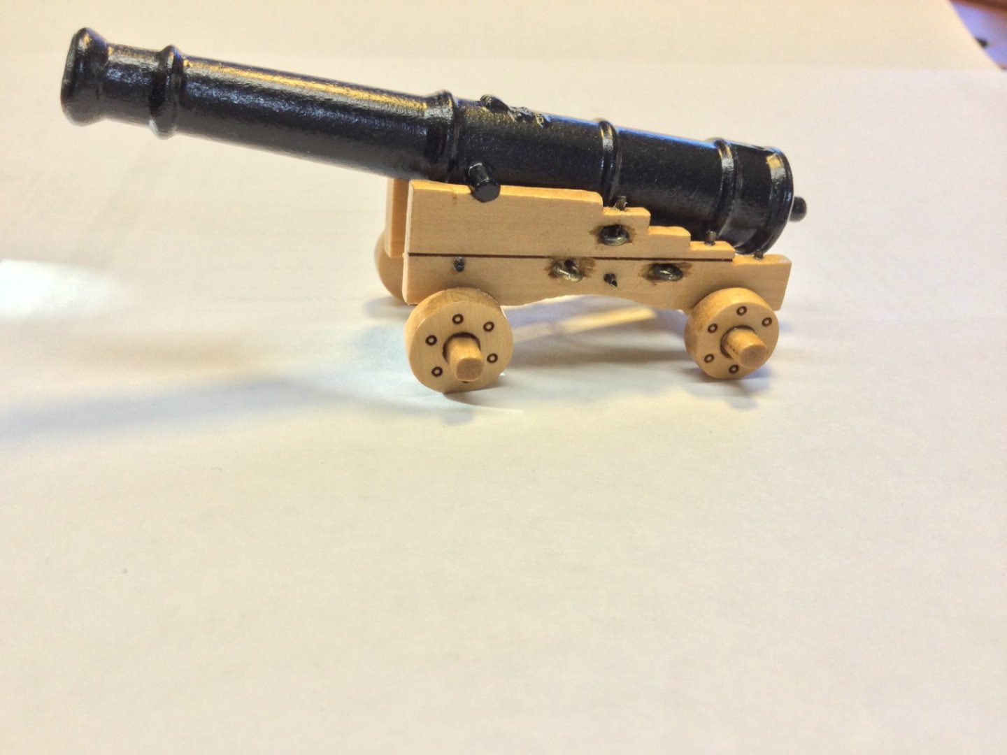
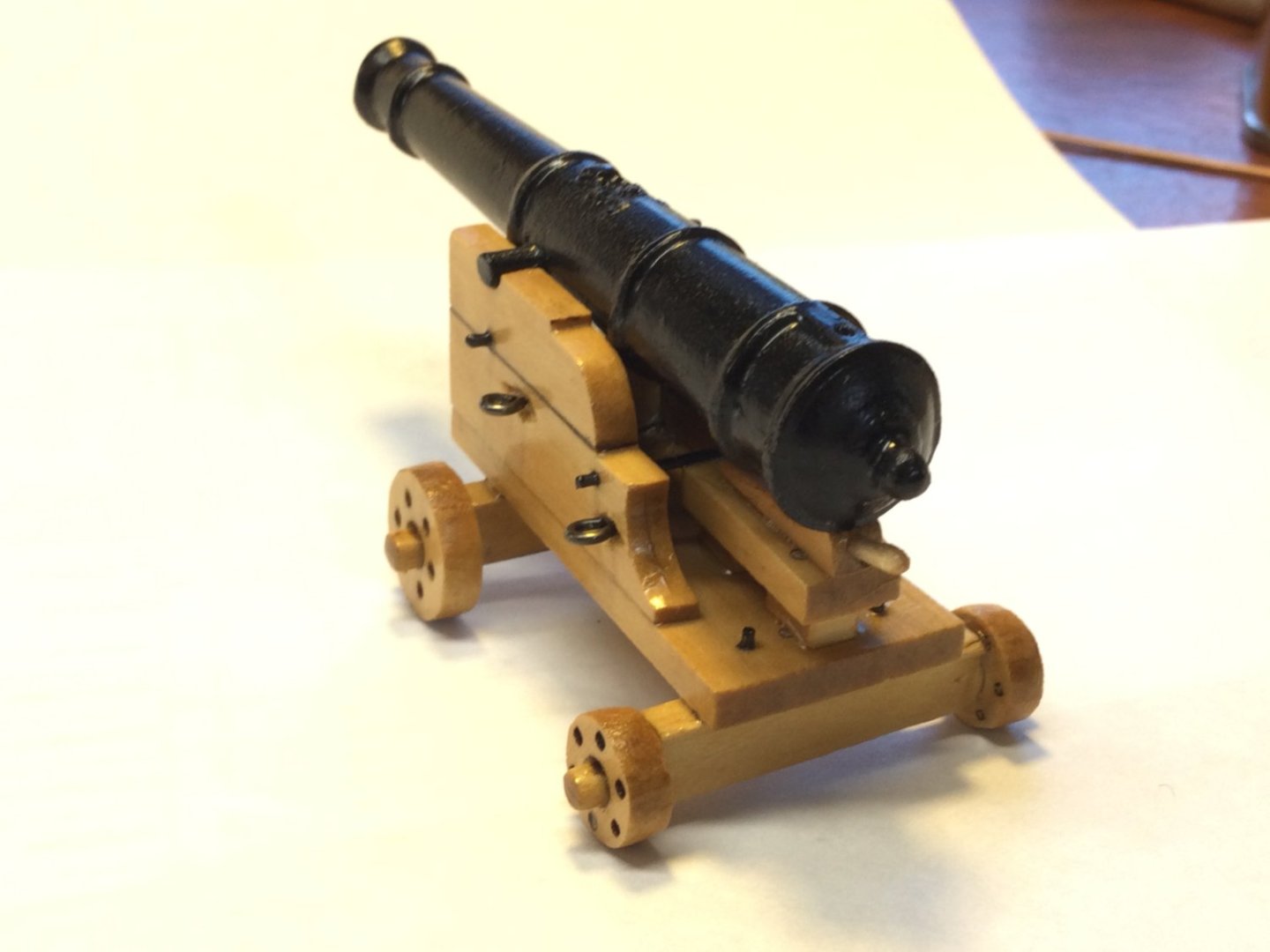
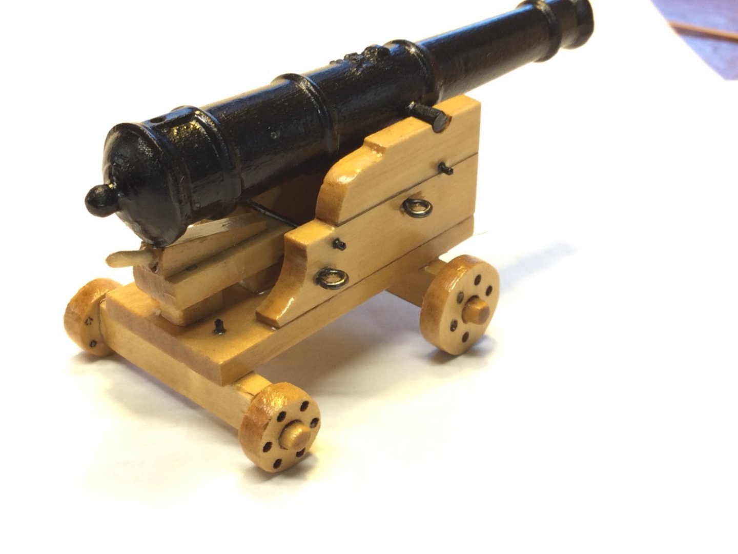
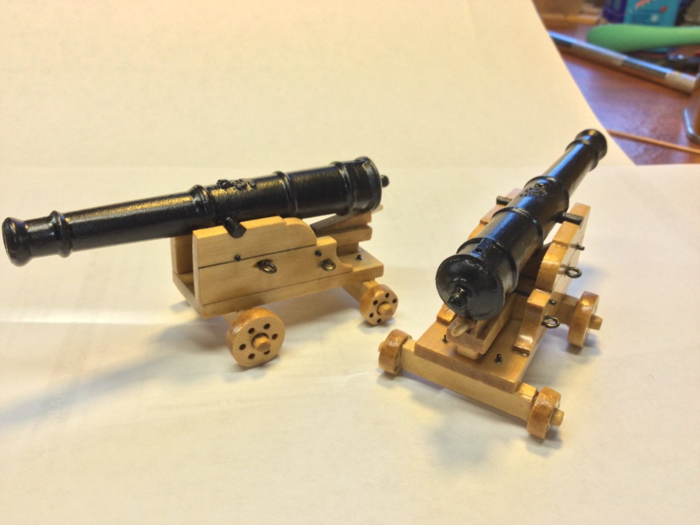
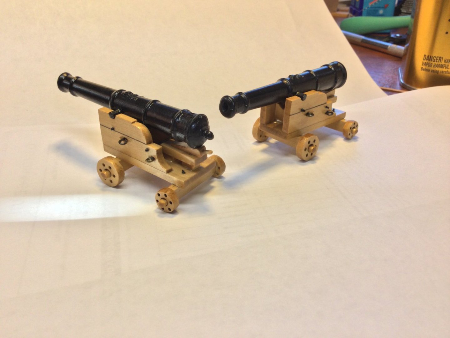
I'm back at it, and started working on fitting the battle stations to the model. I'll show two long gun emplacements just as Jeff's plans call for. Then I realized there was a mistake on the plans! Jeff calls for the guns to be 12 pounders. Granado originally carried eight 4-pounders. The carriages I've built previously are too low for the gun ports!. I decided to scale the long guns Jeff designed for his Battle Station plans and scale them as 4-pounders. I like the style of these guns, also. I get tired of the saw tooth pattern on the brackets of classic English cannon carriages! The first two photos are the 4-pounder carriage that were too short. The others are the final long guns for the model. No cap squares yet!


- 143 replies
-
- 11
-

-
-
Thanks guys…more to come soon!
-
Many of us would be very interested! Who will do the CAD work?
-
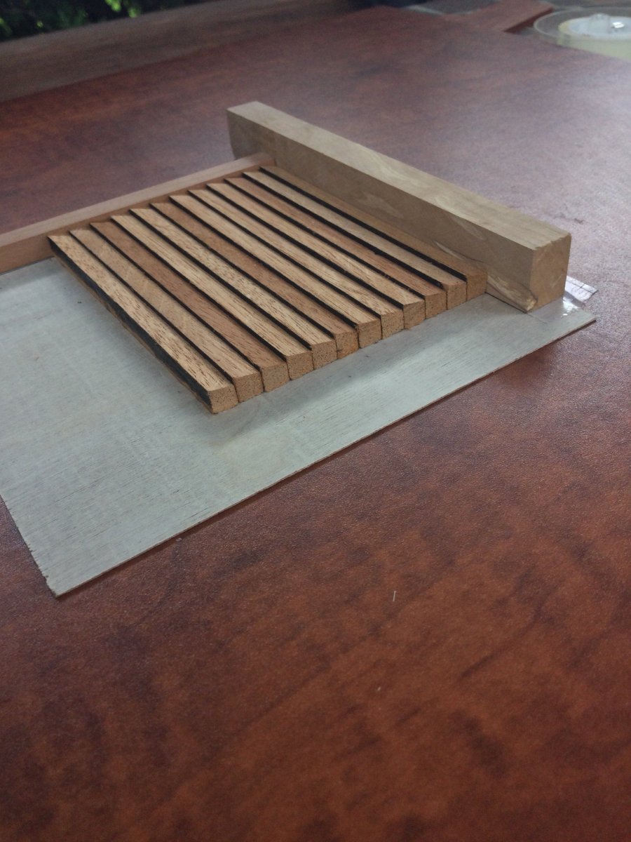
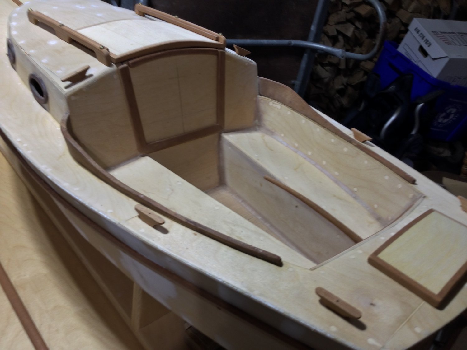
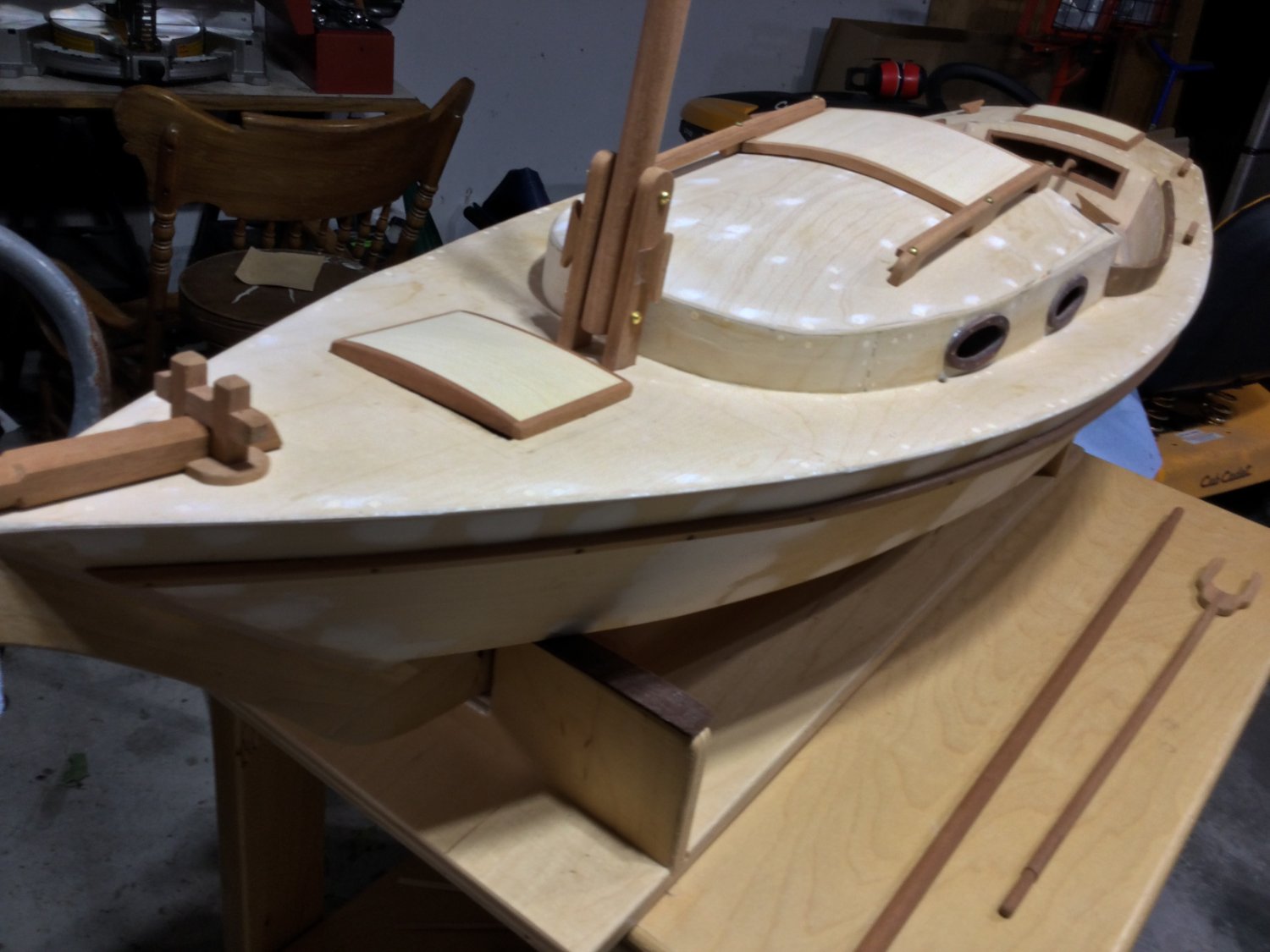
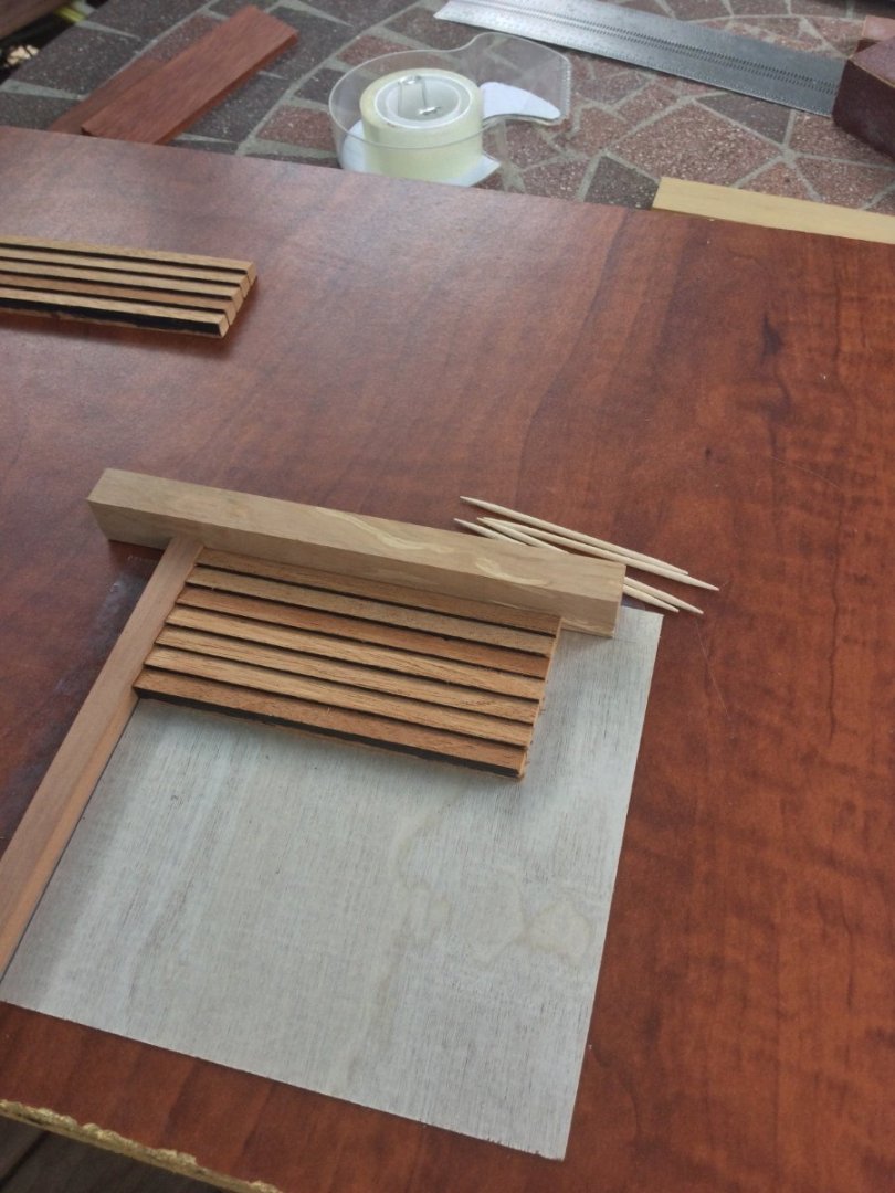
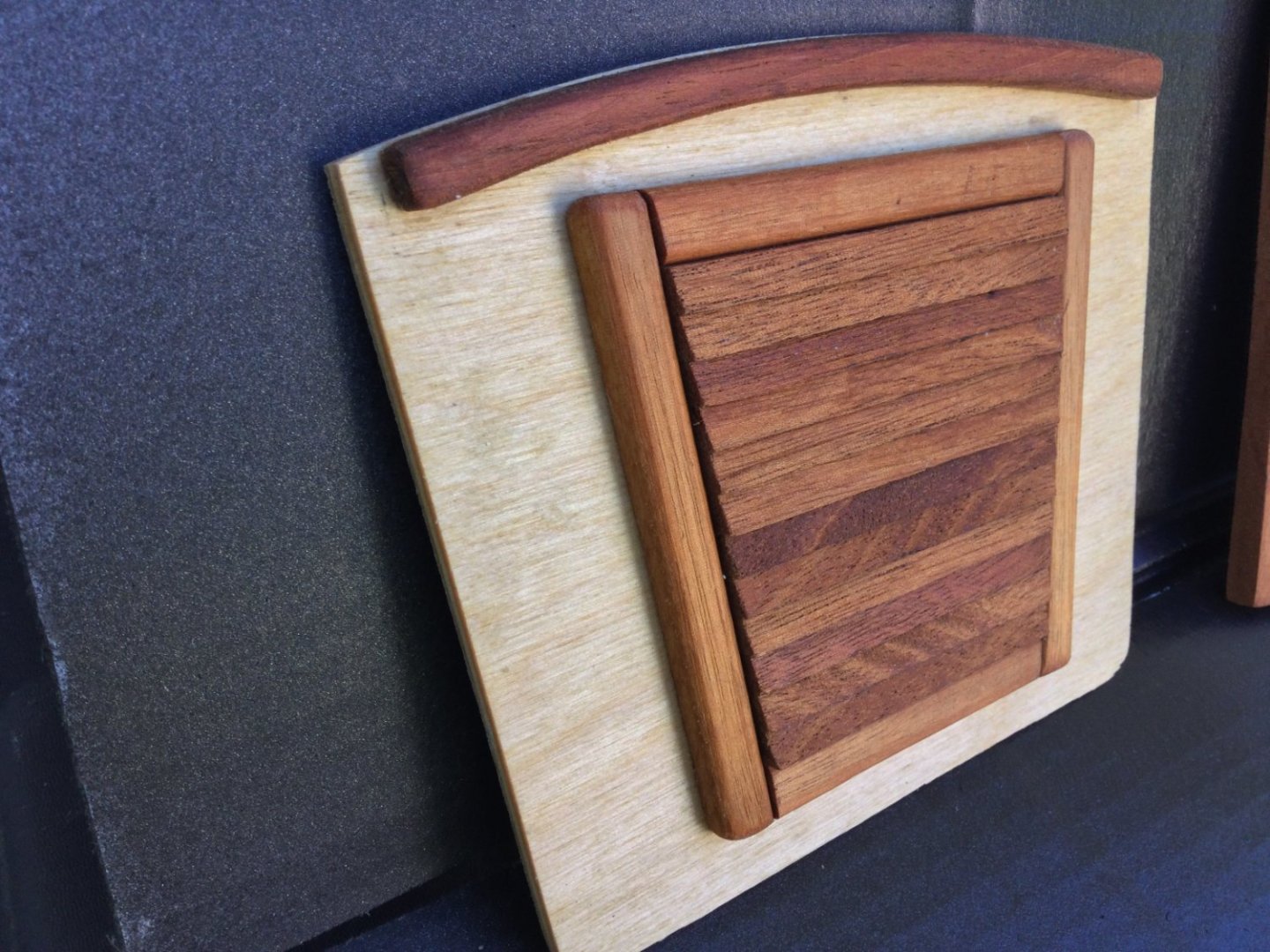
Thanks John! The companionway door hatch on our boat has a functional louver (British spelling = louvre) panel made of mahogany. It allows nice ventilation of the cabin when the forward hatch is open. I wanted to duplicate it, but a functioning louver was just too fussy to attempt, so I simulated it! I cut some slats at an angle and glued them to some 1/32" plywood, then framed the "louver" in mahogany. The final photo is the finished product.

-
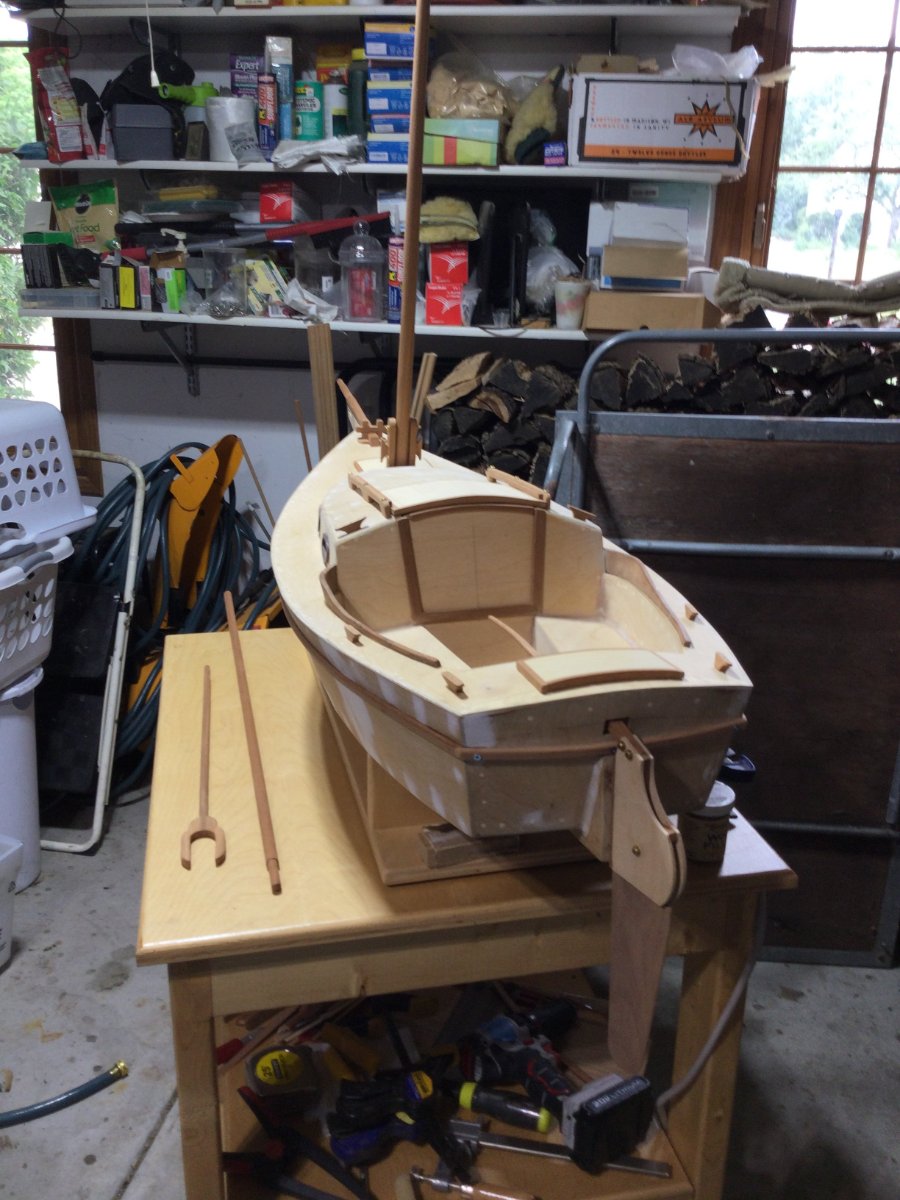
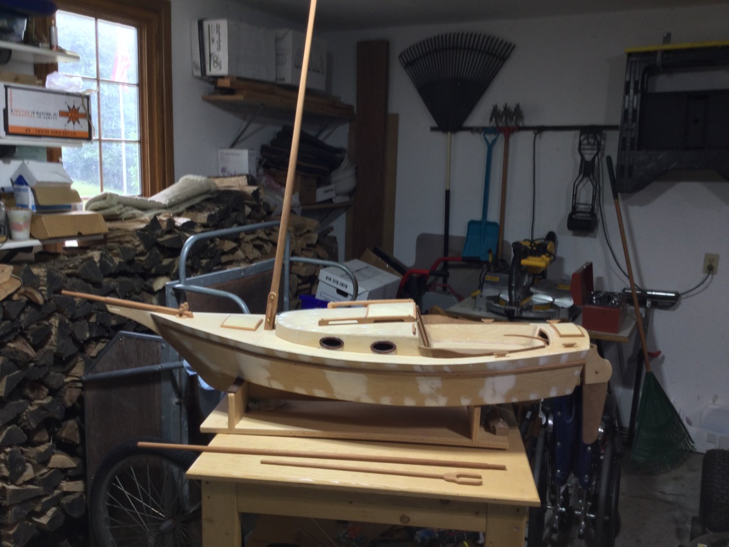
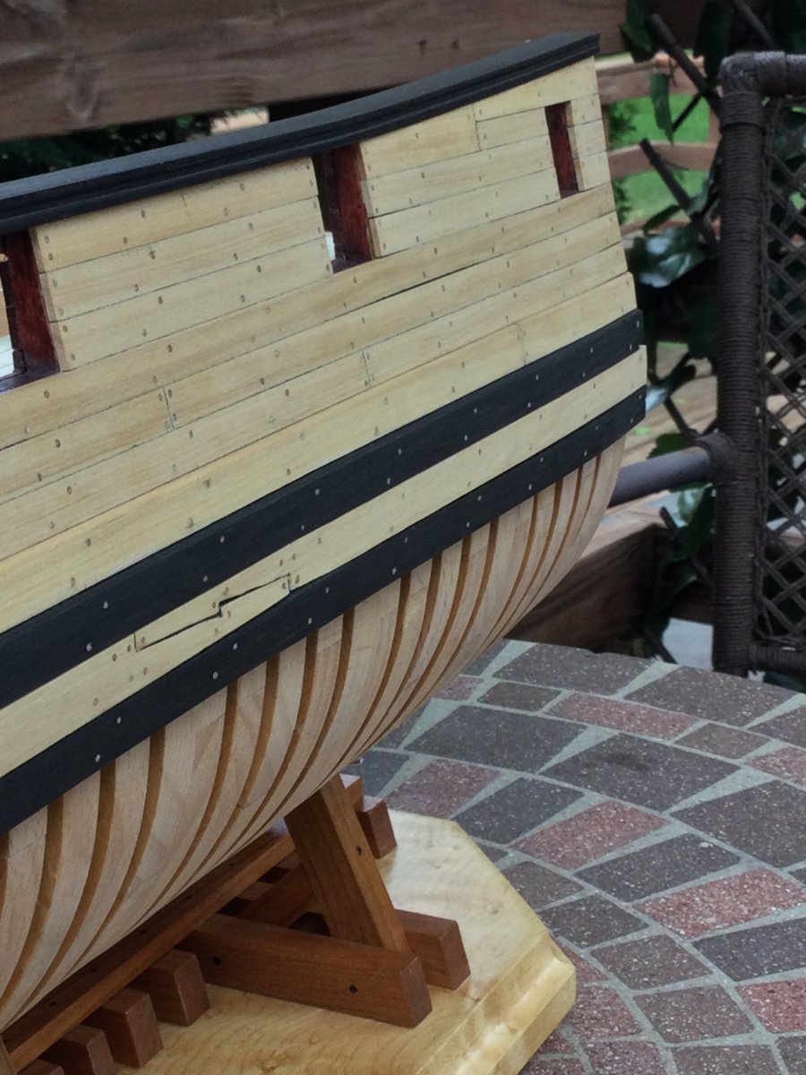
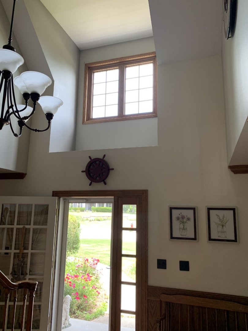
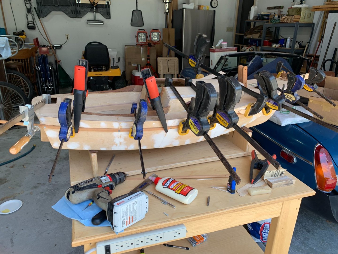
We've done some remodeling in our home, and we have a space to fill. There is a large, second floor dormer alcove overlooking the entry hall with nothing in it! I decided to finally finish the gaff-rigged sloop and display it up there! The first addition was adding the rubbing rails (like wales) made of mahogany. The photos show some of the parts which are already completed, sitting in place (not yet glued). The wood is mahogany and birch plywood. The hull will be flag blue and the topsides will be white. More to come!


-
Is there any thought to making plans available for purchase for a scratch-builder??
-
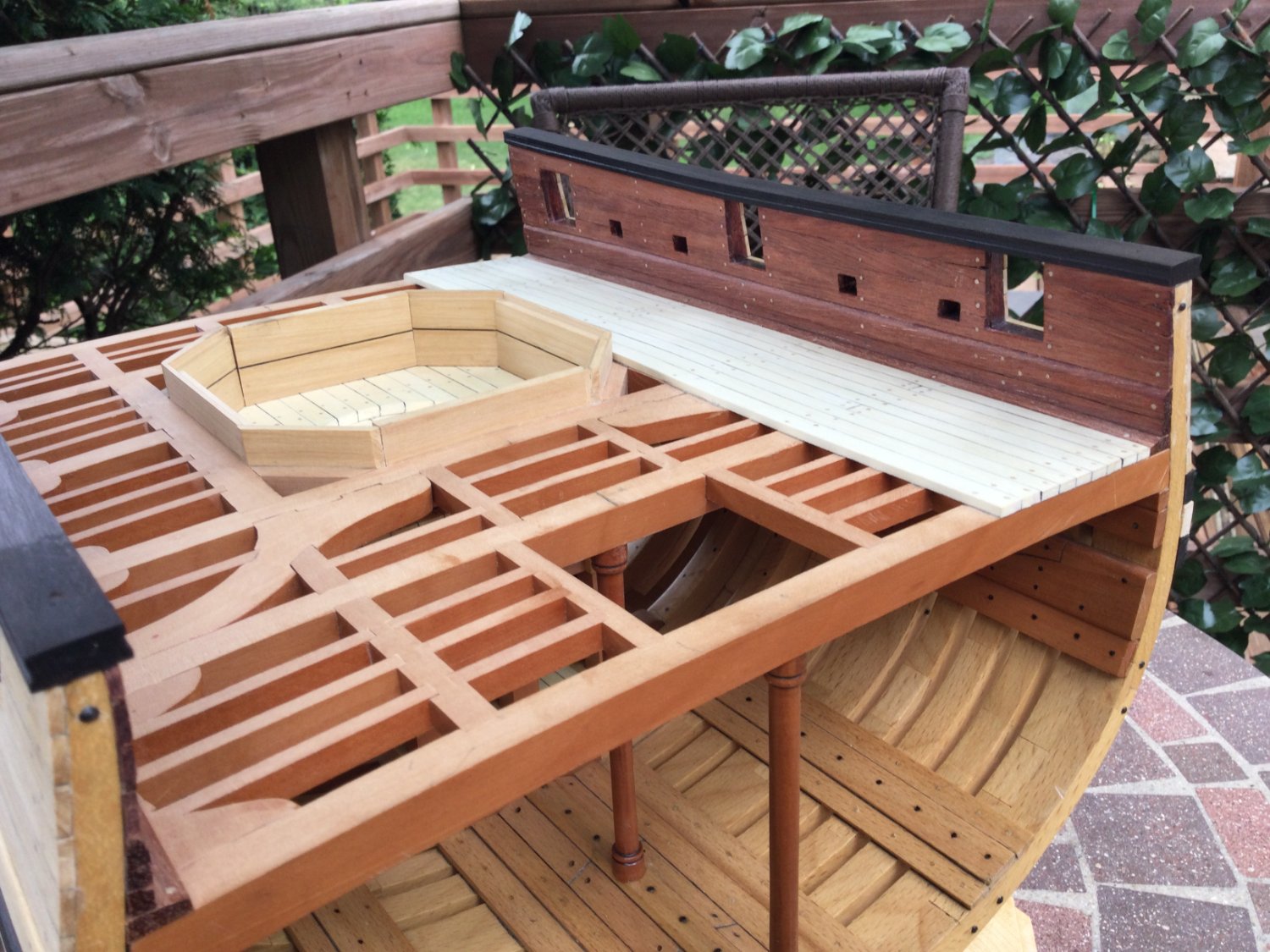
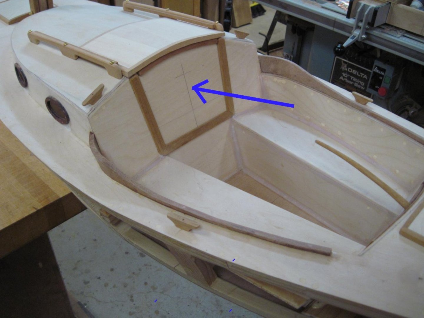
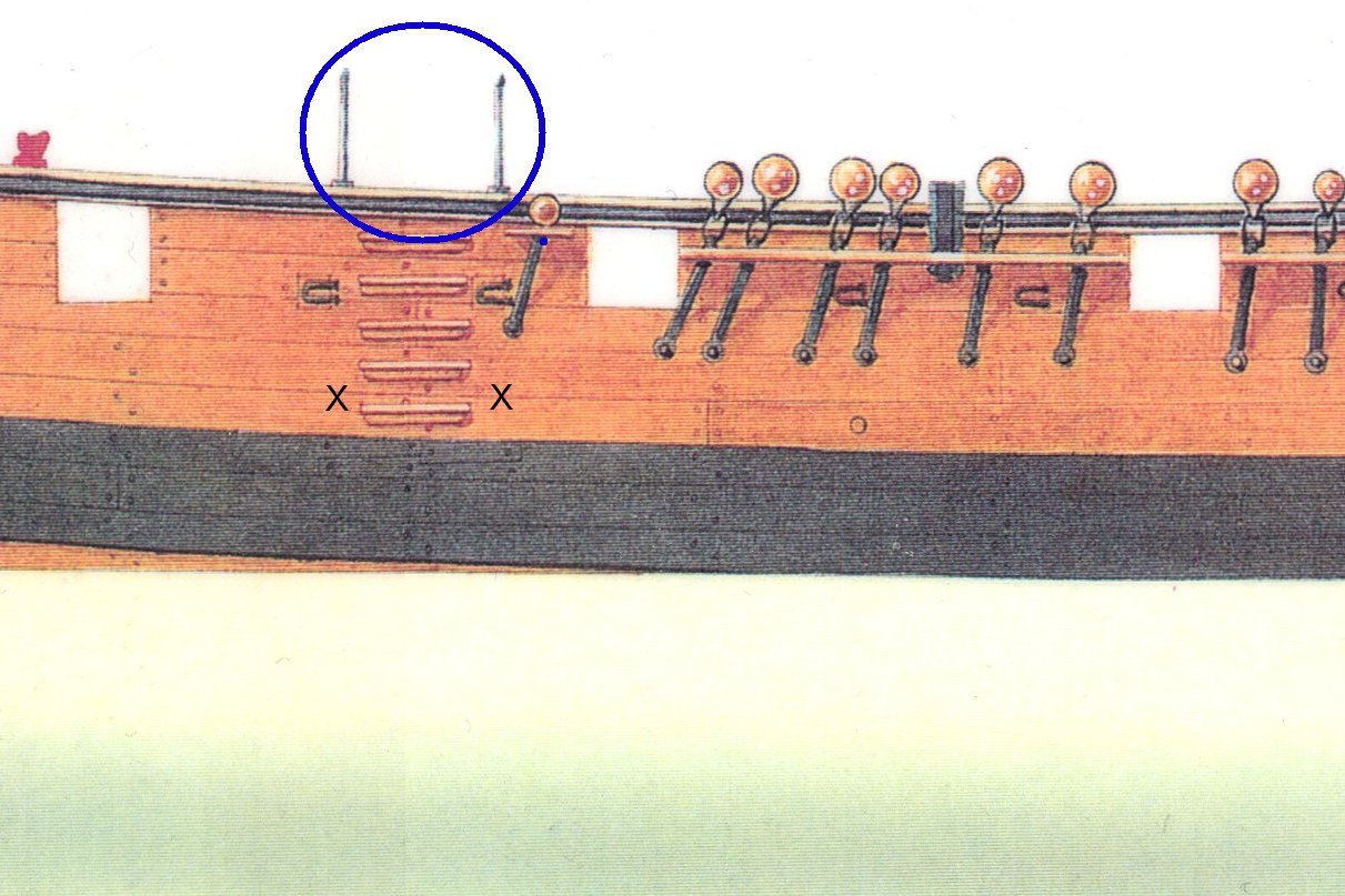
Thanks, guys! I need opinions, guys. On the main rails, on either side of the entry steps and inboard ladders are two stanchions (circled in blue). I assume they have rings at the top to attach lines so that anyone boarding has something to use as a "hand rail" when climbing aboard. Jeff's plans don't include these, and I've not seen them on any of the section models out there. I assume they were removable and made of painted cast iron. Would there also have been ring bolts in the hull where the "X's" are on the photo, to attach the lower end of the hand ropes? Thoughts?
-
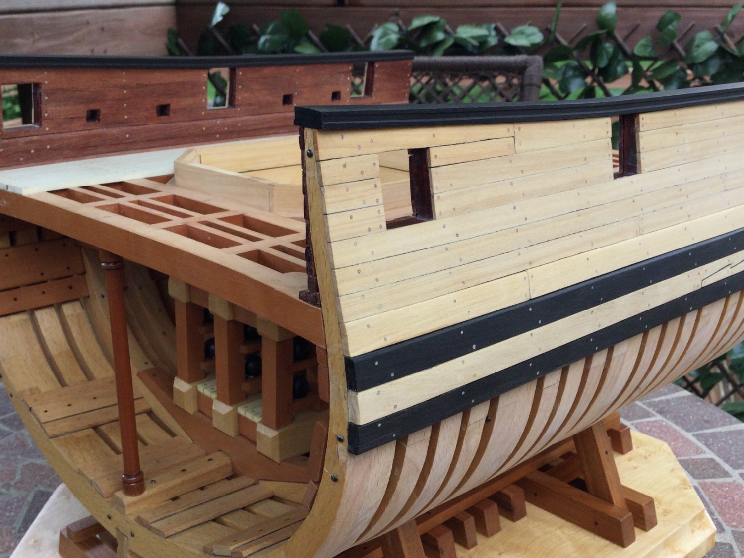
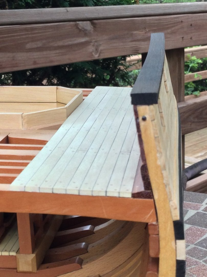
I fit the rails to the bulwarks and clamped them in place. I then drove a couple of little yellow nails to keep them aligned during the glue up. I used 15 minute Bob Smith Industries Epoxy. The photos show the curvature of the rails upward and inward moving aft. There is no poly on the exterior of the model, nor on the main deck or inboard bulwarks. That's why the colors look so washed out! The poly will resuscitate the wood!


- 143 replies
-
- 13
-
-
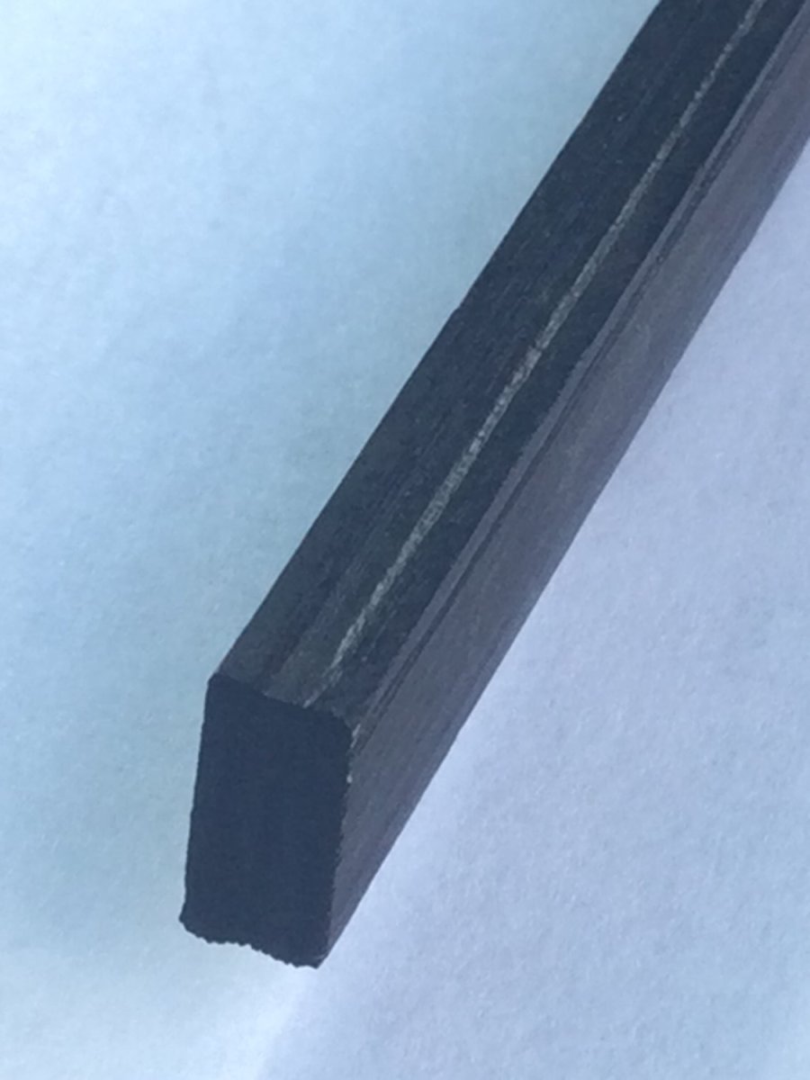
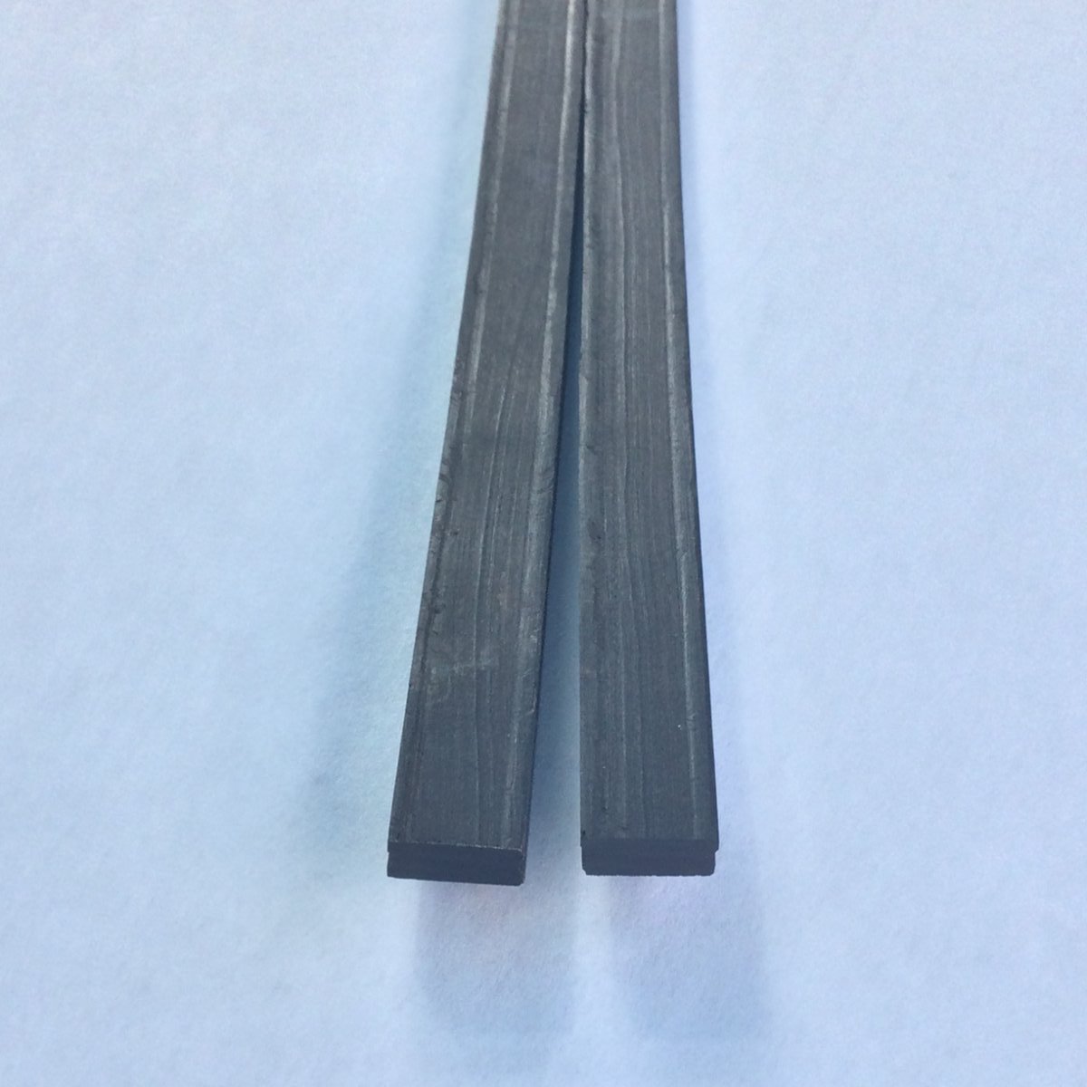
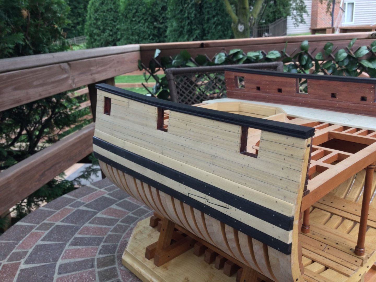
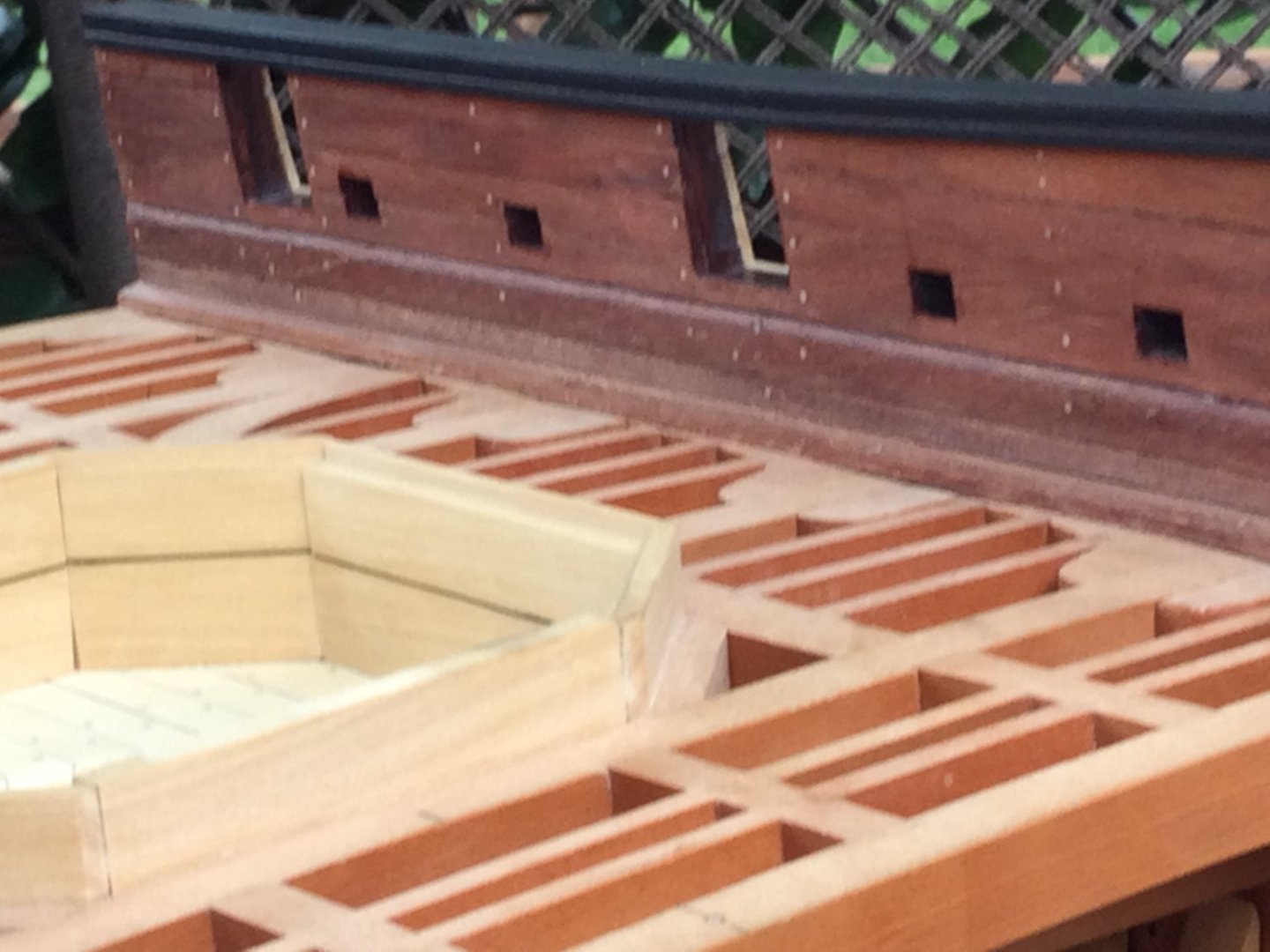
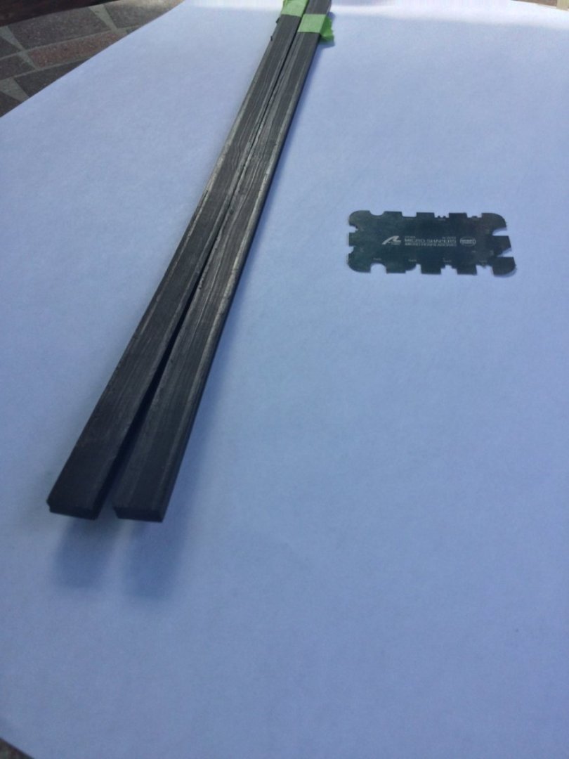
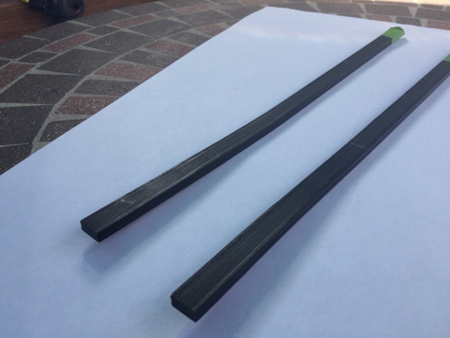
Thanks guys! Next up are the main rails. These are made of ebony, 7/16" wide and7/32" thick. I started by cutting out the blanks a bit long. Then I plowed a decorative rabbet into the inboard and outboard edges of each rail using an Artesania Latina scraper. The rails rise moving aft over the last 8 frames, and there is a distinct narrowing of the hull over the last 4 frames. That means the rails must be curved upward quite a bit as well as inward. Using ebony, this wasn't easy! I used a Milwaukee brand heat gun to do the compound bend it two steps. This is really a hit-or-miss proposition as it's difficult to "undo" a mistake after the wood is bent. Have extra rail blanks! I got lucky and both rails bent correctly the first time. The photos show the rail blanks after bending.


-
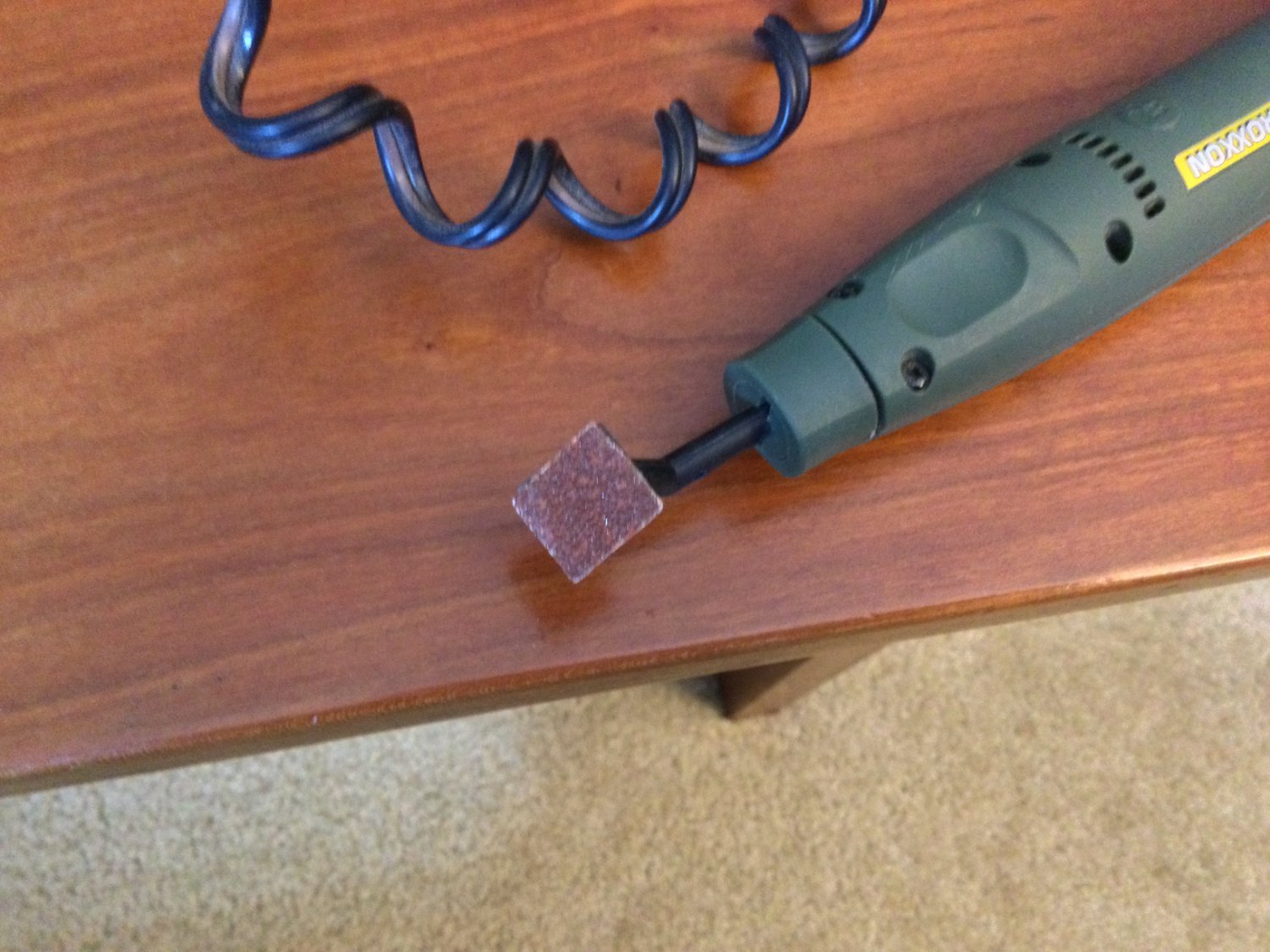
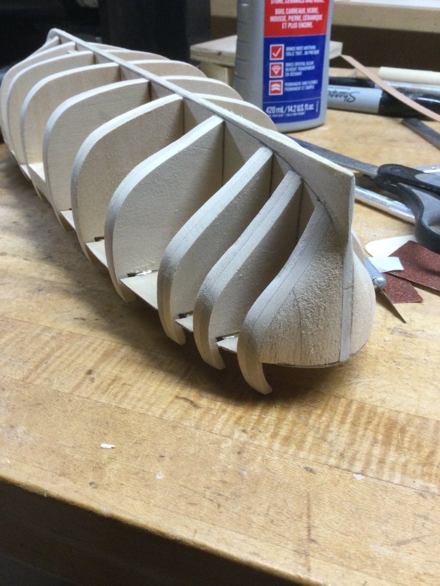
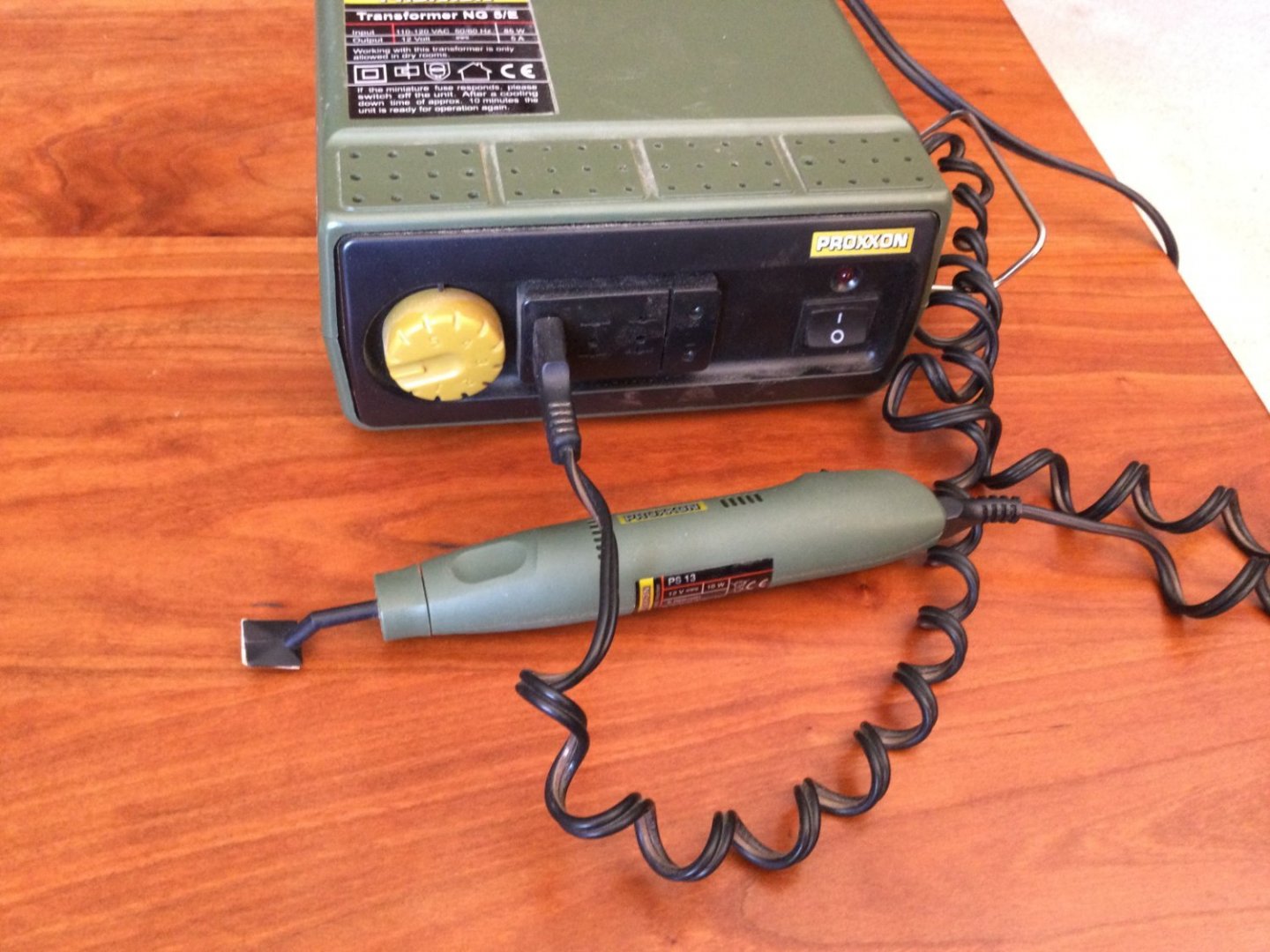
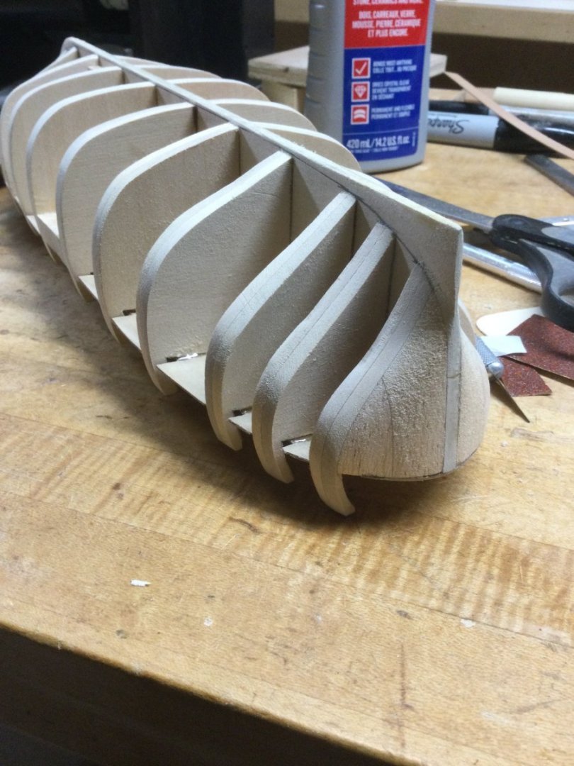
Hi Pat! Not really necessary to seal the balsa. The next task was to thin the bulkhead extensions. They were left thick to allow fairing of the outside of the hull. The inside surfaces then need thinning. I use X-Acto blades and a Proxxon detail sander with 60 grit adhesive backed sandpaper. Worked well. No broken extensions because of the two thicknesses of basswood ninety degrees to each other.


- 17 replies
-
- 11
-
-
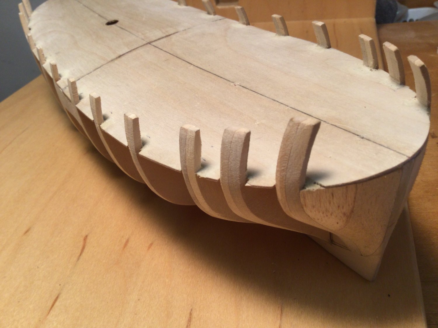
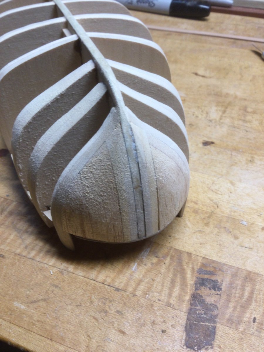
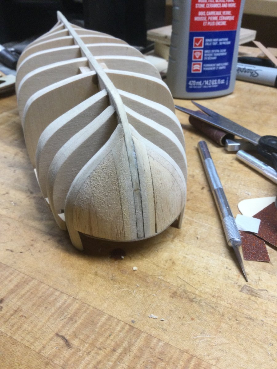
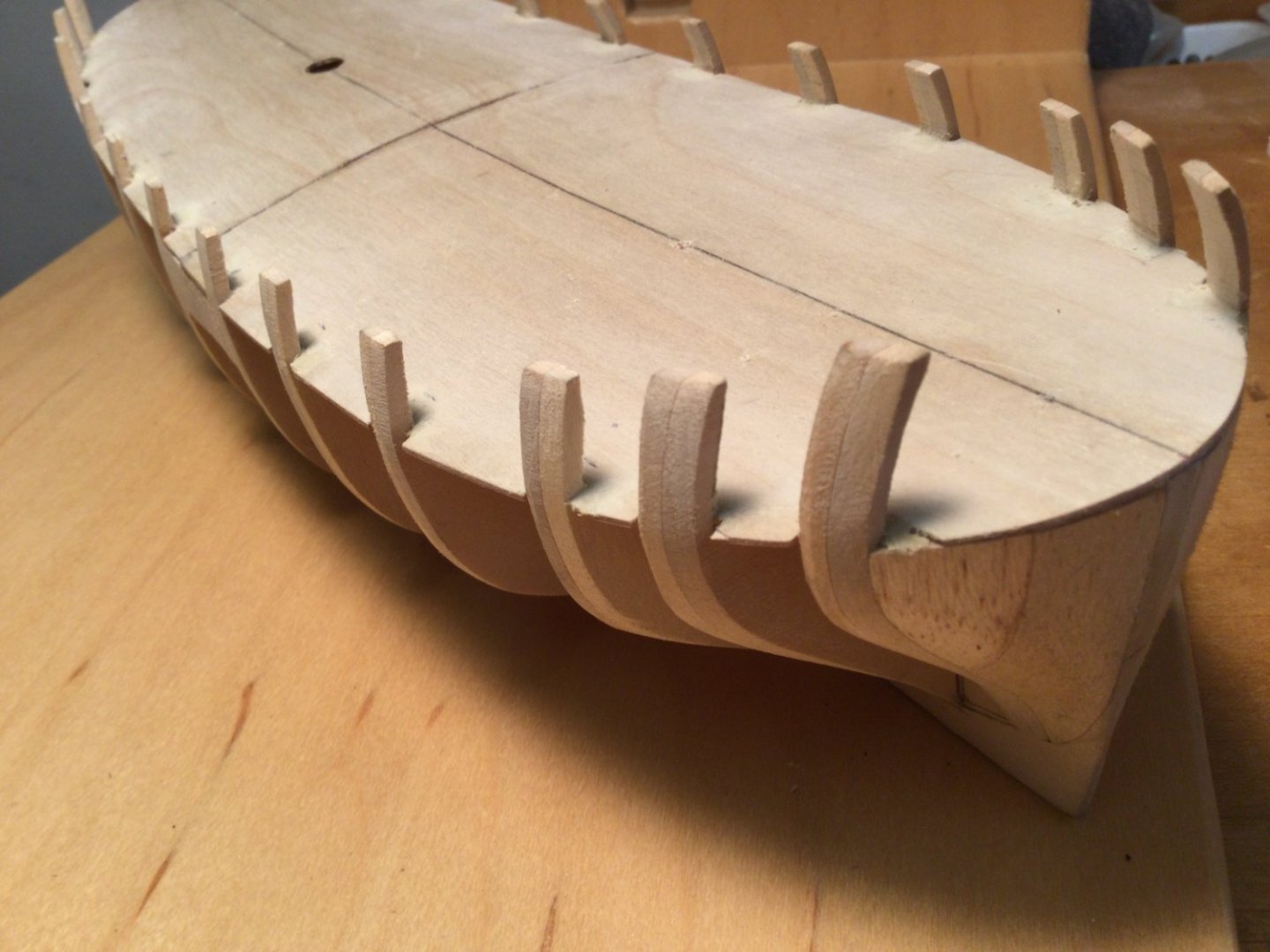
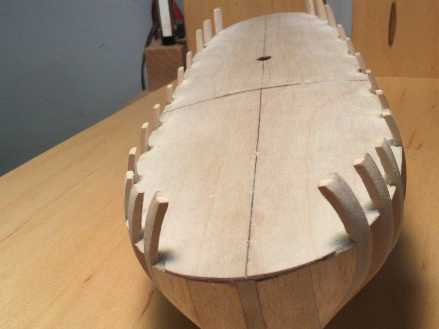
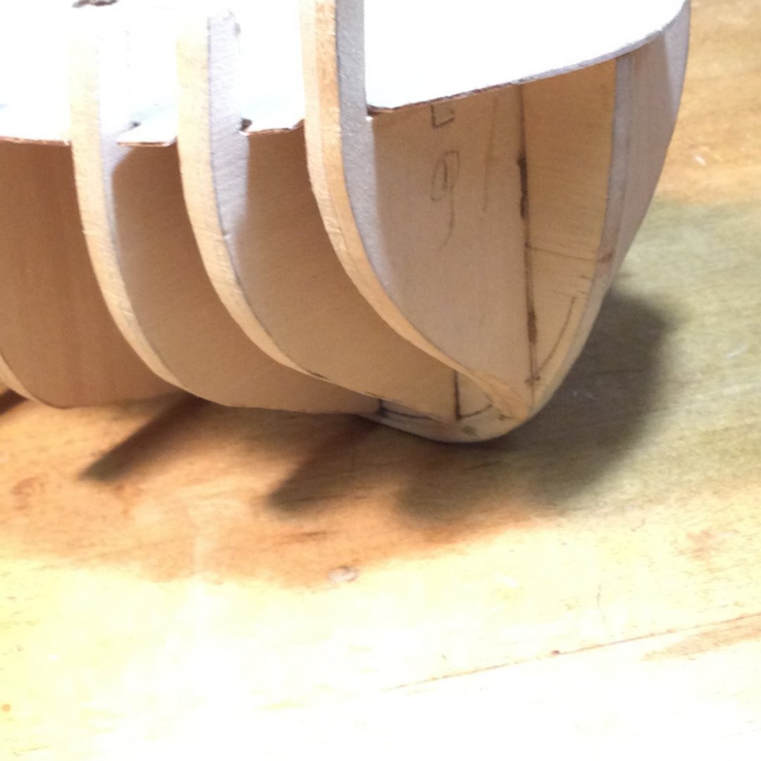
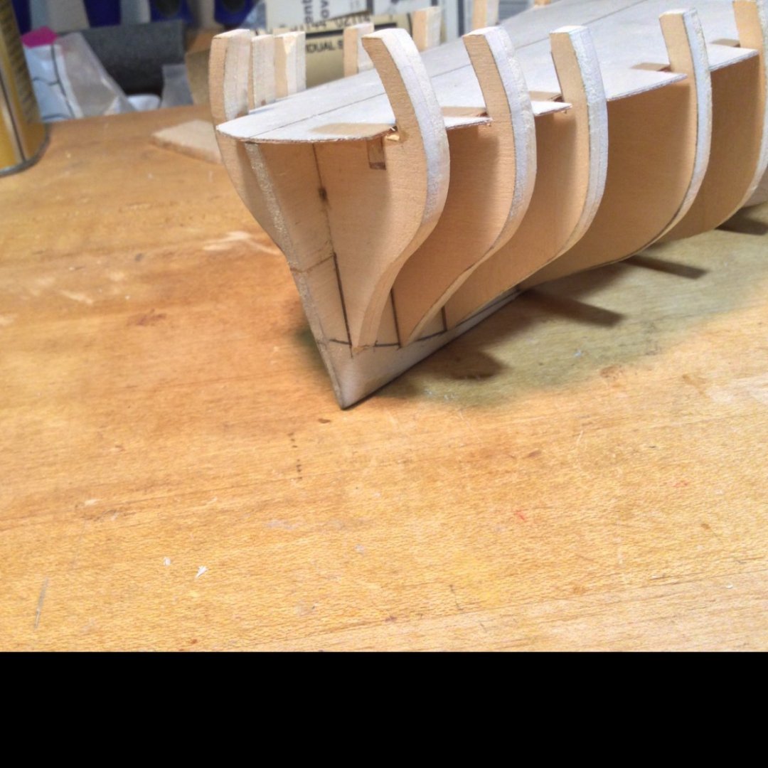
I fitted the bow and stern filler blocks. They are balsa wood so they shaped easily. The filler blocks and the frames were then faired. No problem with any of the bulkhead extensions breaking due to the double thickness of cross-grained basswood making up the bulkhead blanks.


- 17 replies
-
- 11
-
-
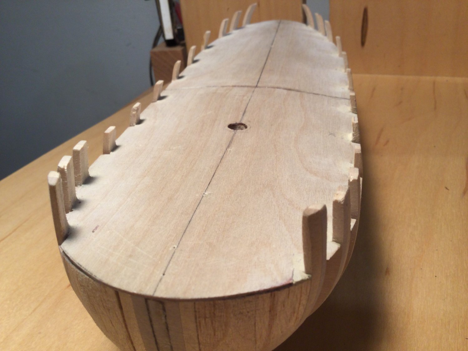
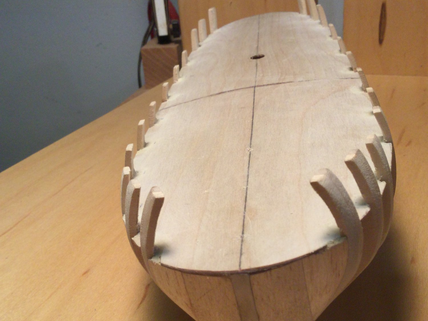
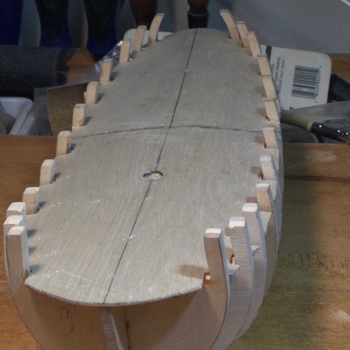
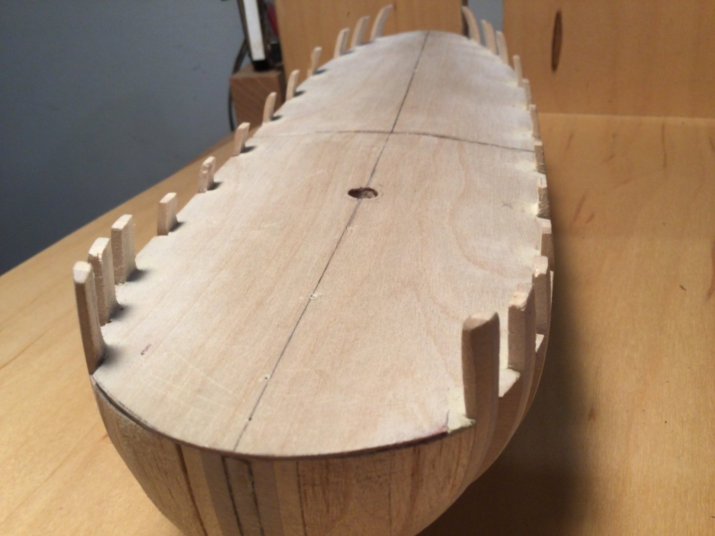
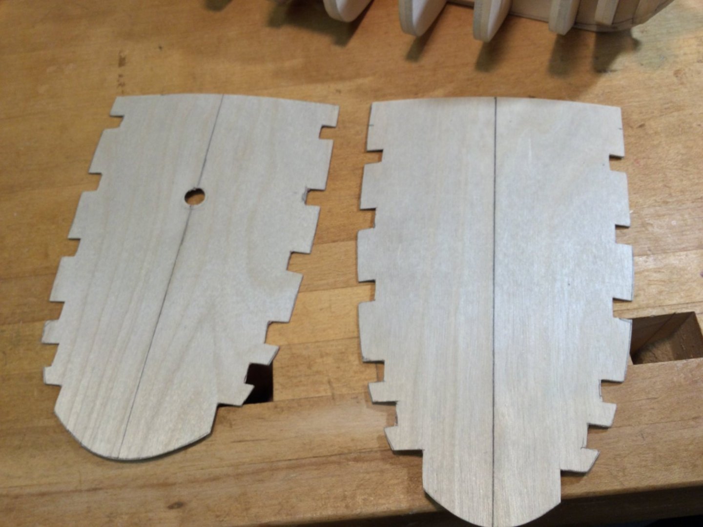
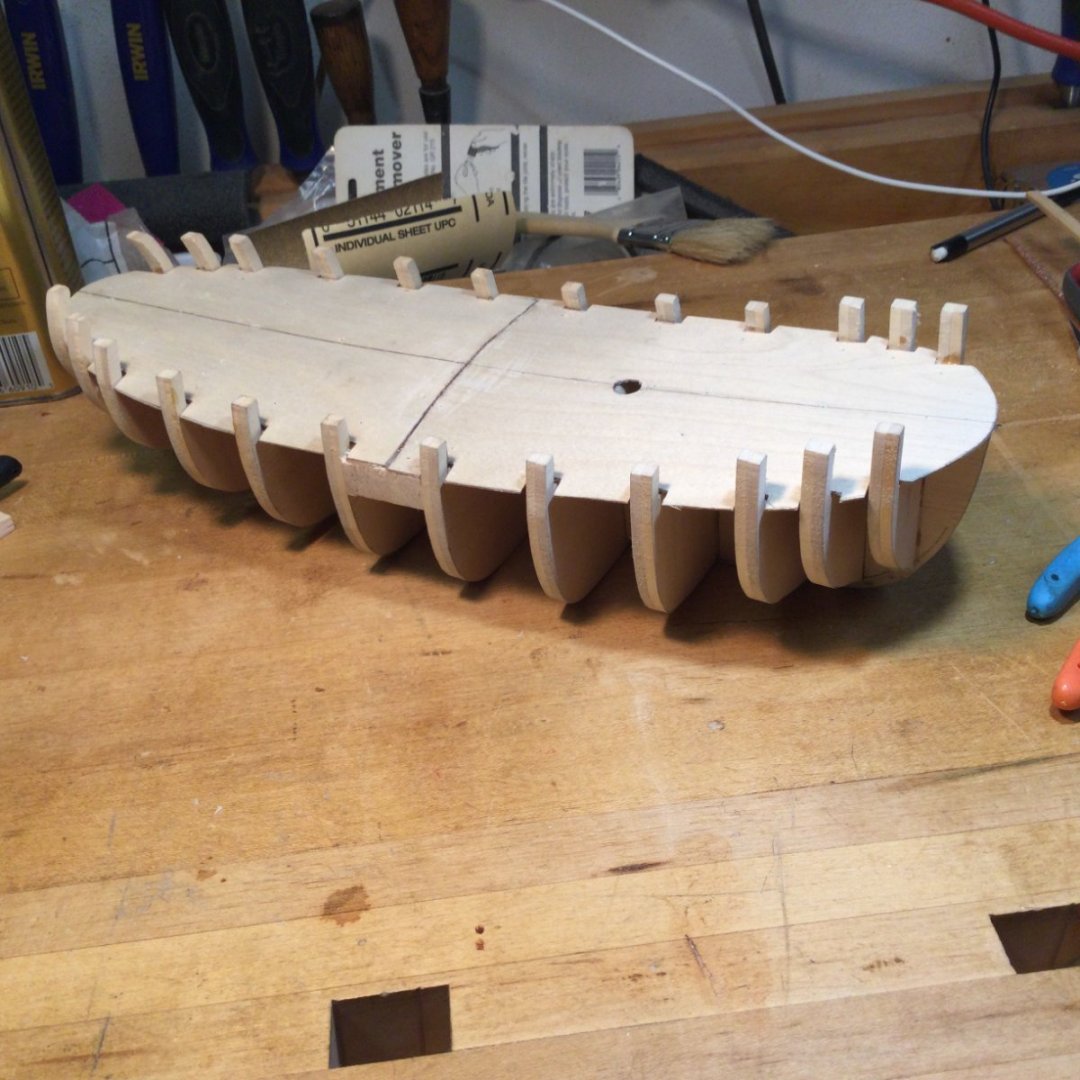
As mentioned, the sub deck is made in two pieces. I used 1/32” plywood because it bends easily and you can cut it with a pair of scissors! Since there is a second final layer of decking, I wasn’t too concerned about how tight the tolerances were for the notches that accommodate the bulwark extensions. I framed in the mast step on the profile former, drew a centerline on both pieces of subdeck, drilled the mast hole and then glued down the sub deck using 30 minute epoxy and those little yellow nails that come with every model ship kit! When the glue dried I removed the nails. The next task is bow and stern filler blocks. There is a bluff bow and the stern is pretty rounded also.

- 17 replies
-
- 13
-
-
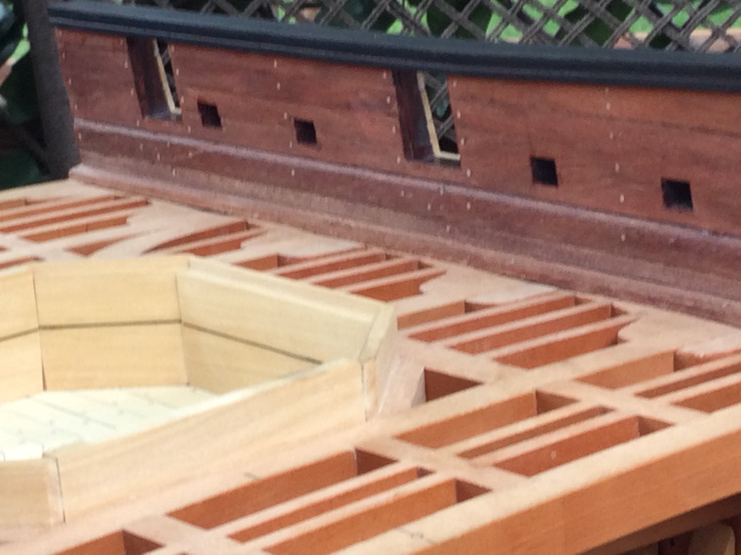
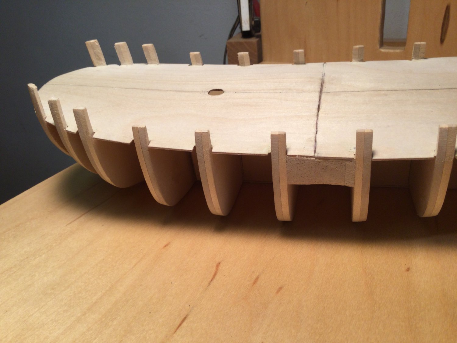
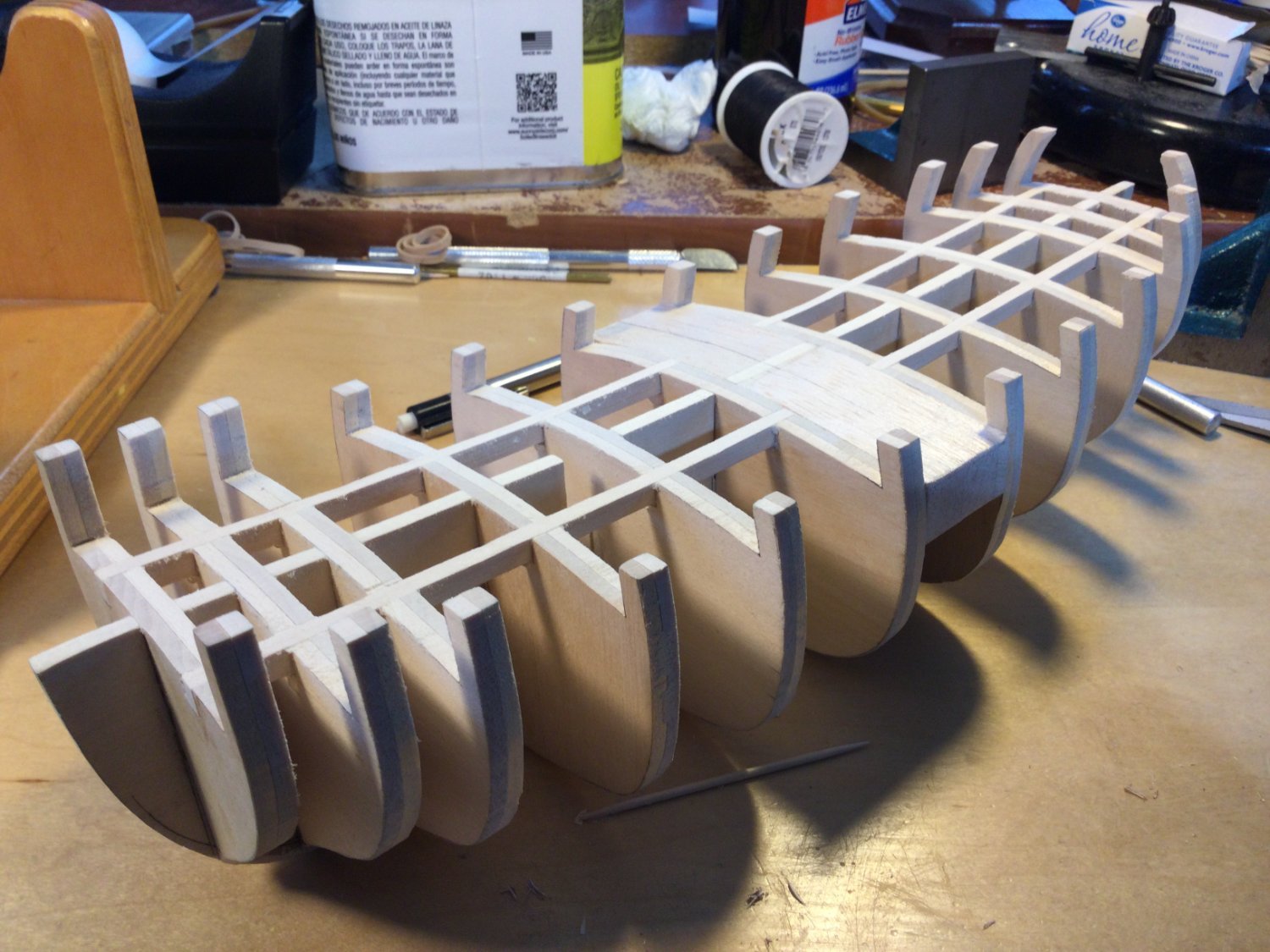
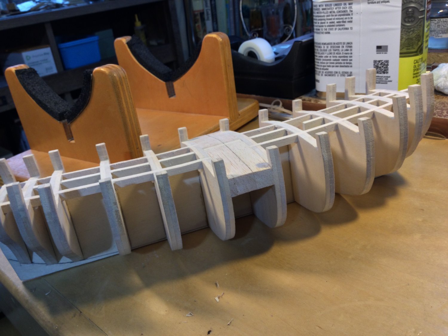
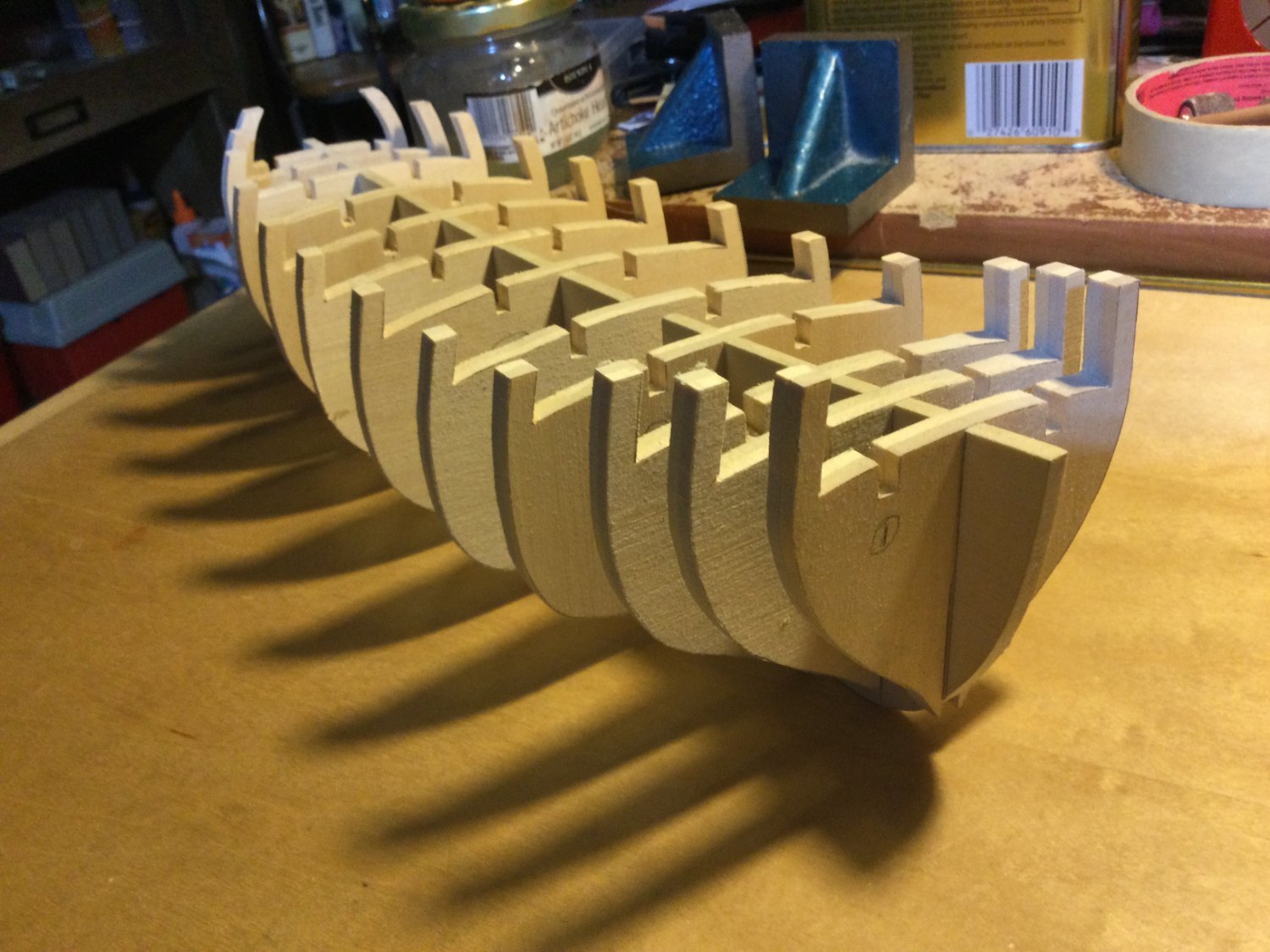
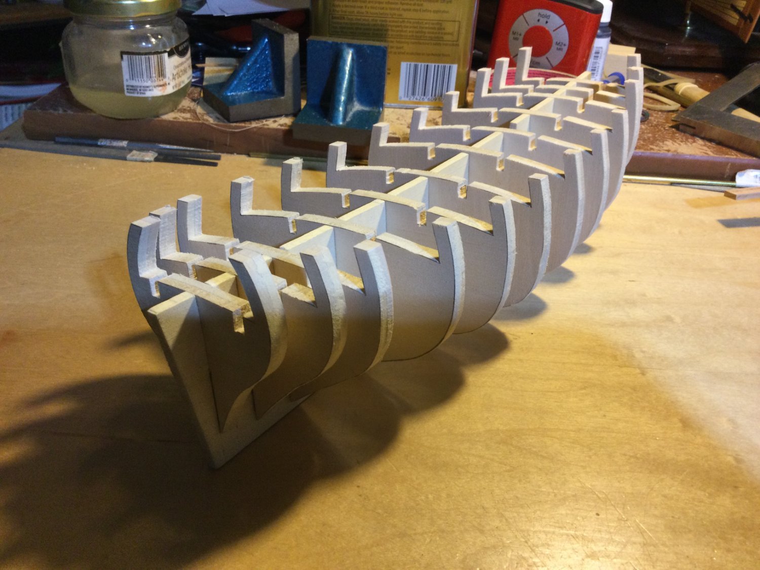
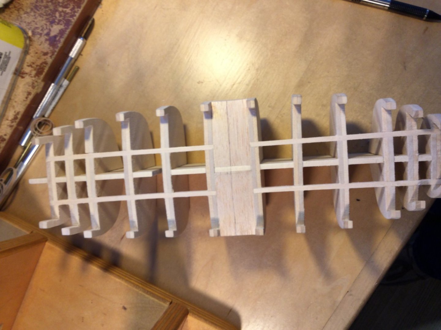
The subdeck is difficult to fit because of the bulwark tumblehome at the bow and the stern. I’ll make it in two pieces. I blocked in the space between bulkheads #6 and #7 to provide a gluing surface for the edges of the two pieces. I then made the stringers and glued them in the rabbets. When dry, I trimmed them and sanded the whole framework top. Next is to install the subdeck. You can see the bearding line drawn in on the middle photo.


- 17 replies
-
- 13
-
-
Thanks, Pat. After drawing in a bearding line and the rabbet, I tapered the lower edge of the false keel to proper size and glued the frame together.


- 17 replies
-
- 12
-
-
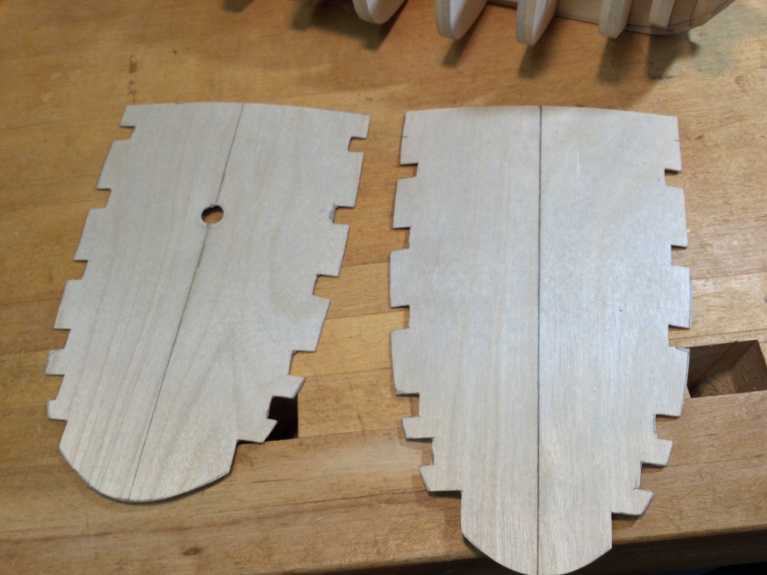
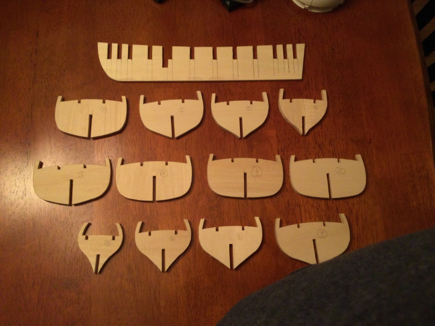
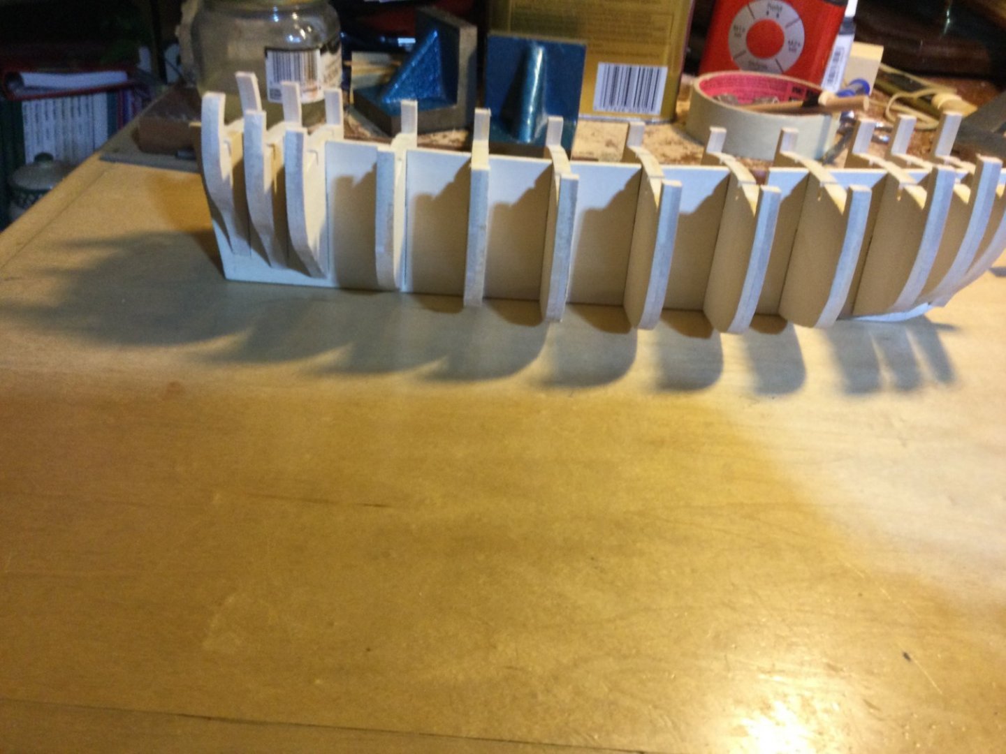
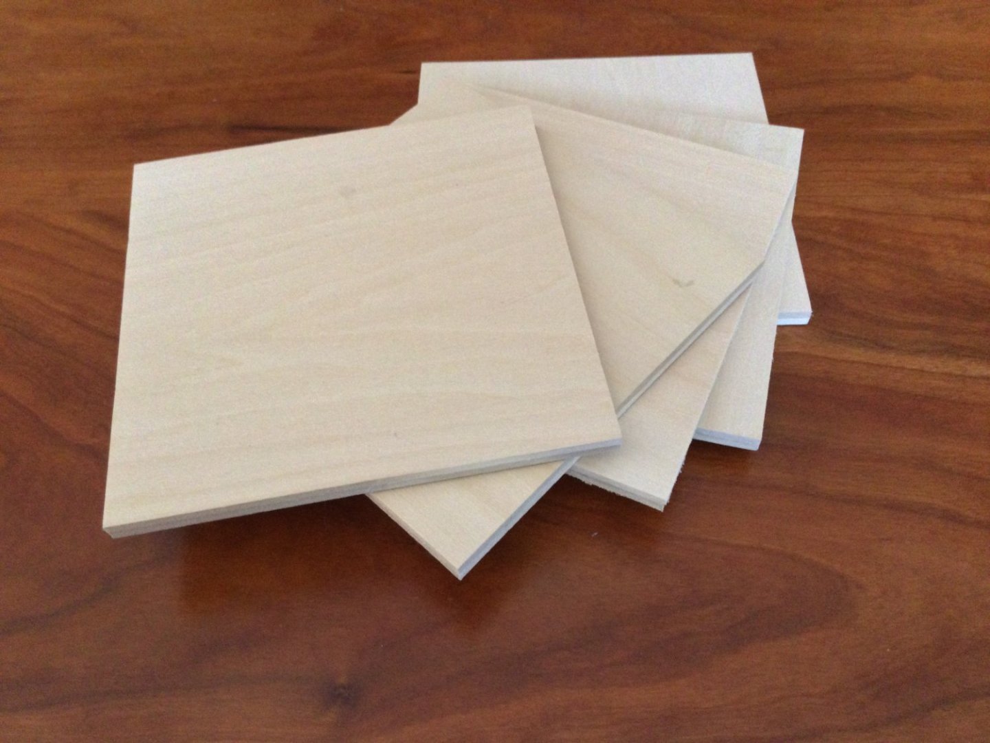
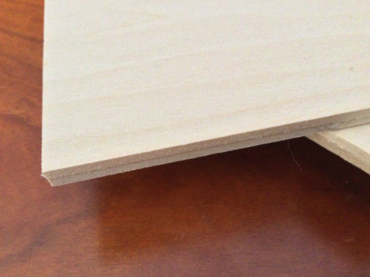
The bulwark extensions on the bulkheads would be harder to fair if made of plywood, but if basswood were used, they would be very fragile and likely to break. I solved the problem by making up a blank for each bulkhead. These were two 1/8" thick squares of basswood glued togther. I glued them so the grain of each was at 90 degrees from the other. This prevented breakage of the bulwark extensions. I also ploughed dadoes into each bulkhead so I could fit basswood stringers to stiffen the frame. Easier than blocking each frame. The final bulkheads are ¼” thick. You can see the two layers in the second photo. The third photo shows the layout of the profile former before cutting and the last photo is of all the bulkheads ready to be glued up! Note the tumblehome of the fore and aft bulkhead extensions. That may be a problem a little later!

- 17 replies
-
- 13
-
-
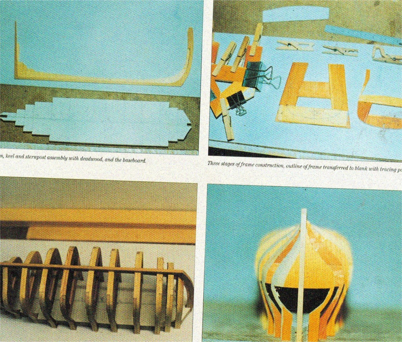
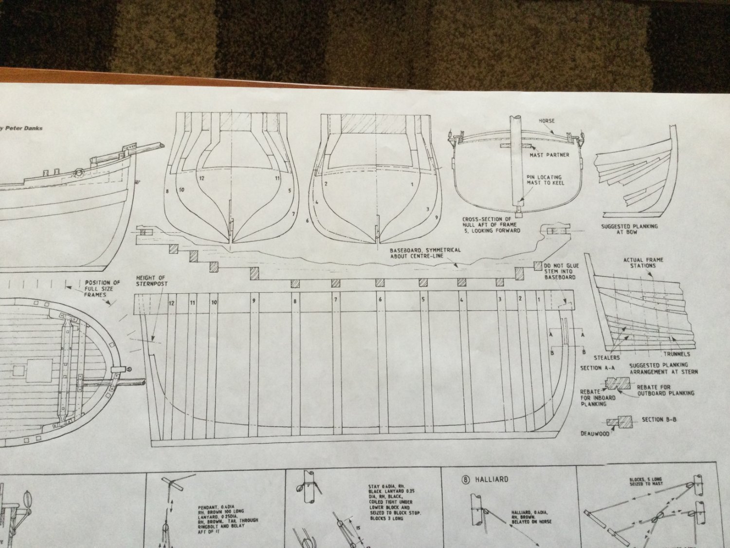
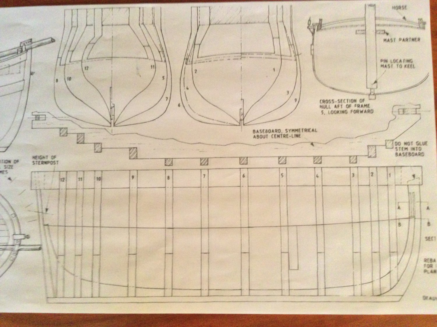
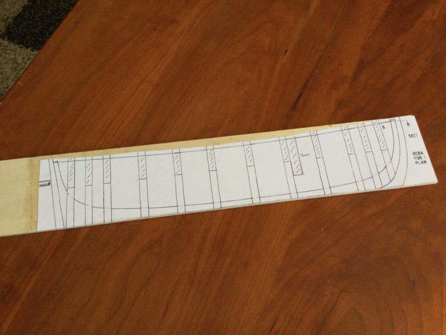
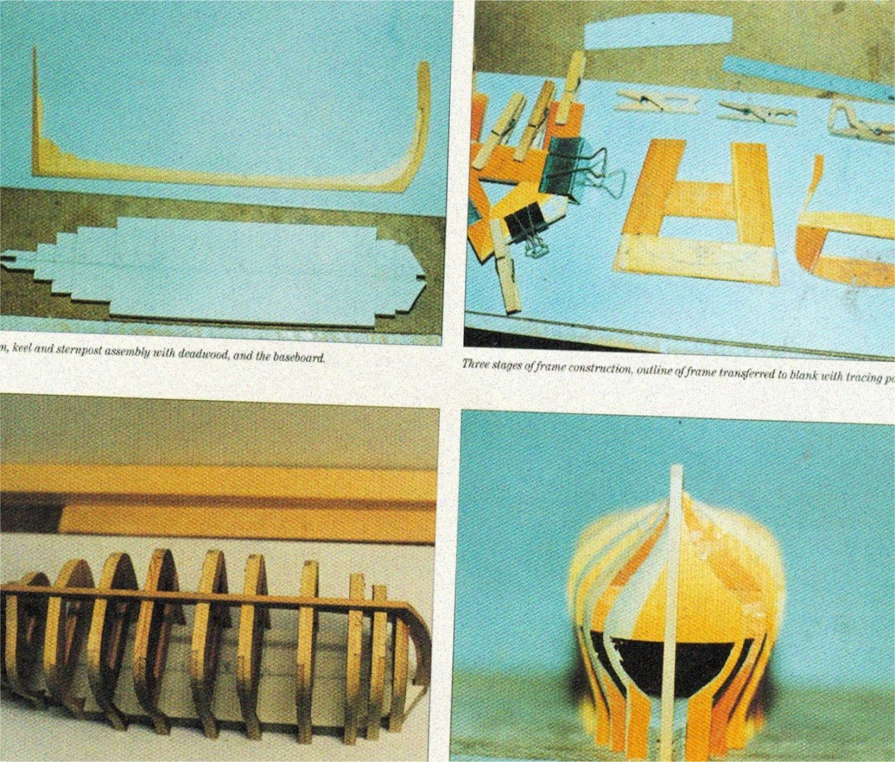
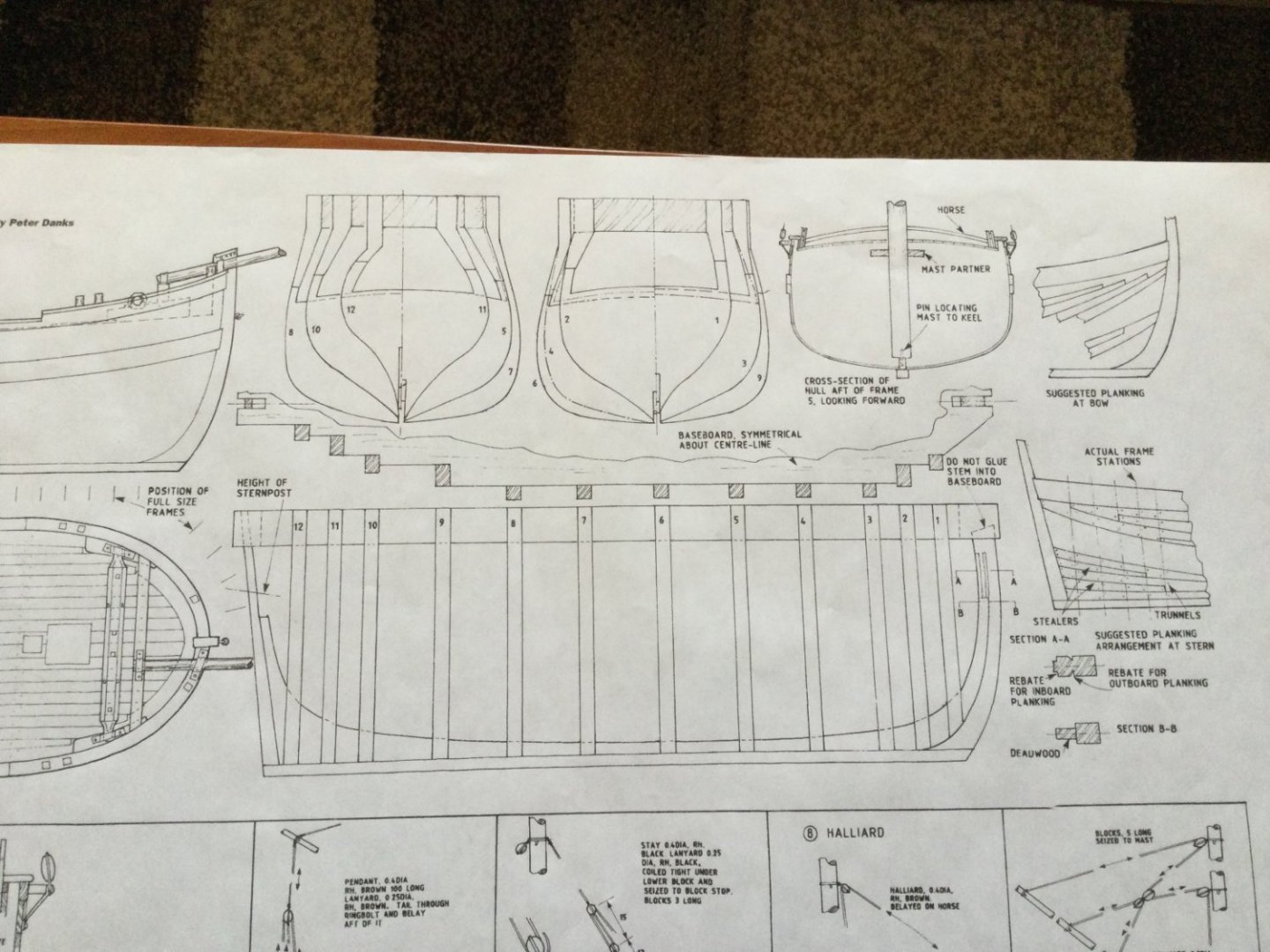
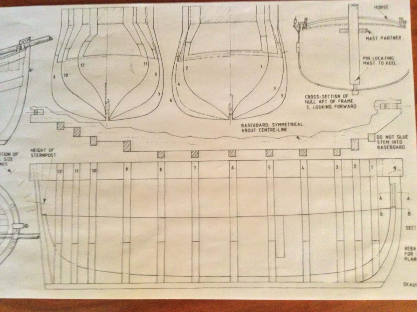
I happened to have a copy of the March, 1993 issue of Model Boats magazine which had an article by Peter Danks about building this small coasting vessel. It included a full set of plans, which I had digitized so I could copy selected parts of the plans as needed. The model is about 13” long without the sprit, so enlarging the plans to 1:32 results in a model that is still reasonable for the average house! I abandoned my usual preference for larger scales and decided to build at 1:48 for a change of pace! The construction technique in the original plans was weird. It employed a strange jig that was INSIDE the model, and the model was built upside down, with extensions glued to the jig like a Hahn style POF. The model was then cut from the jig after planking the exterior. I decided to go a different way. I converted the skeleton to a typical POB model, with a central false keel and bulkheads. This was challenging because the plans don’t include a water line or bearding line and the station lines, which form the basis of the bulkhead, are poorly drawn. I made up foam board mockups of the bulkheads and false keel before I made the final versions in basswood. The first photo (on page 2 of Danks’ article) shows the odd construction plans and the weird up-side-down inside out jig. There is even (un-necessary) deadwood! The second photo shows the profile and the station lines which I used to draw the false keel and plan the bulkhead locations. The third photo shows the sheer line of the deck drawn in, which defines the top of the false keel as well as the slots for locating the bulkheads.
- 17 replies
-
- 11
-
-
Thanks for your interest, guys! There are a lot of real challenges involved in building this little ship…not the least of which is the extended hatch to the cargo hold. The framing for than long hatch curves across the beam to match the deck camber, but also fore and aft to match the deck sheer. I plan to also change the wooden slats which cover the hatch opening from flat to curved. Lots of solid geometry to contend with. I suspect that part of the build may take a month to complete, with multiple trial and error attempts. Challenging and fun!
-
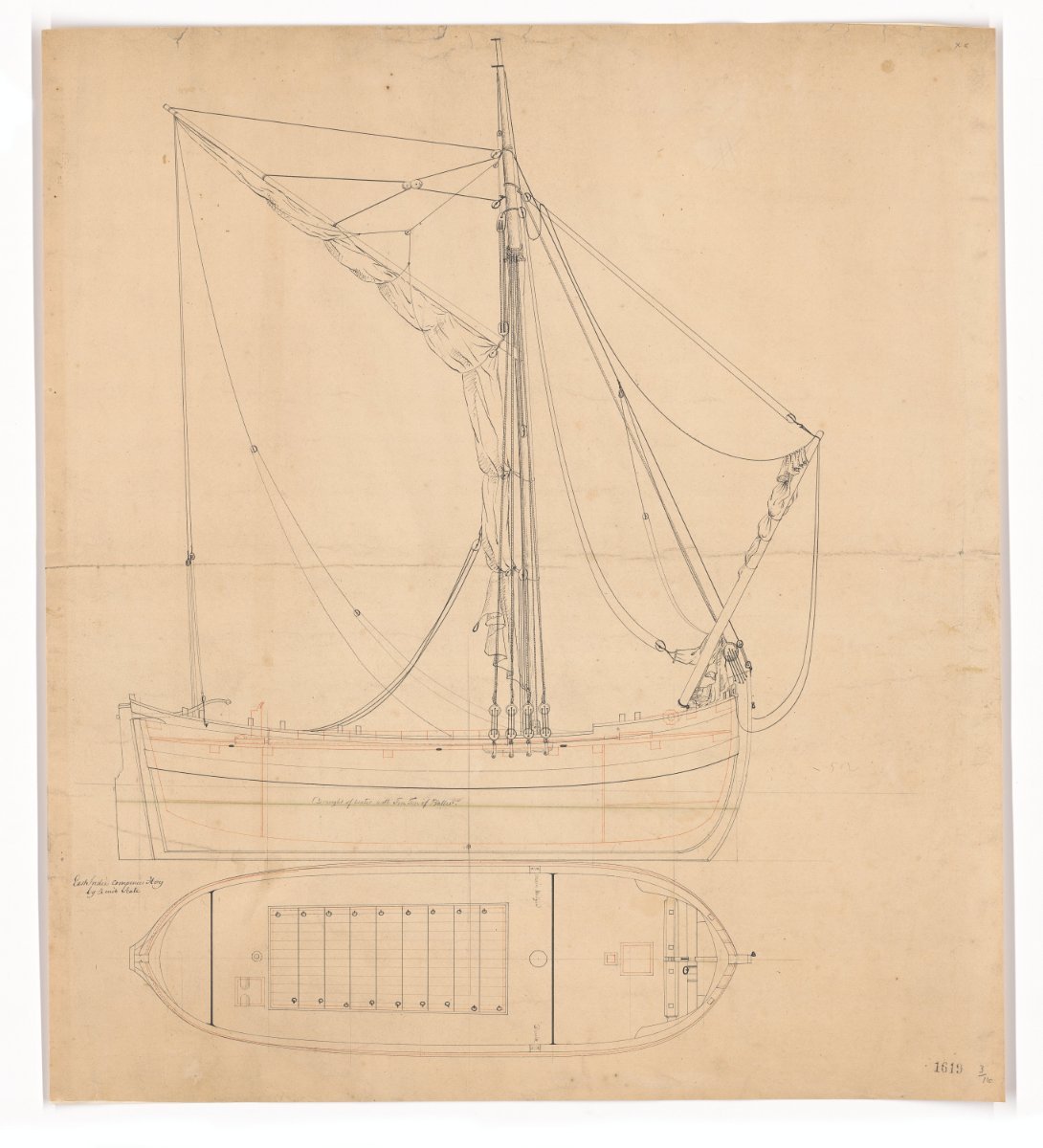
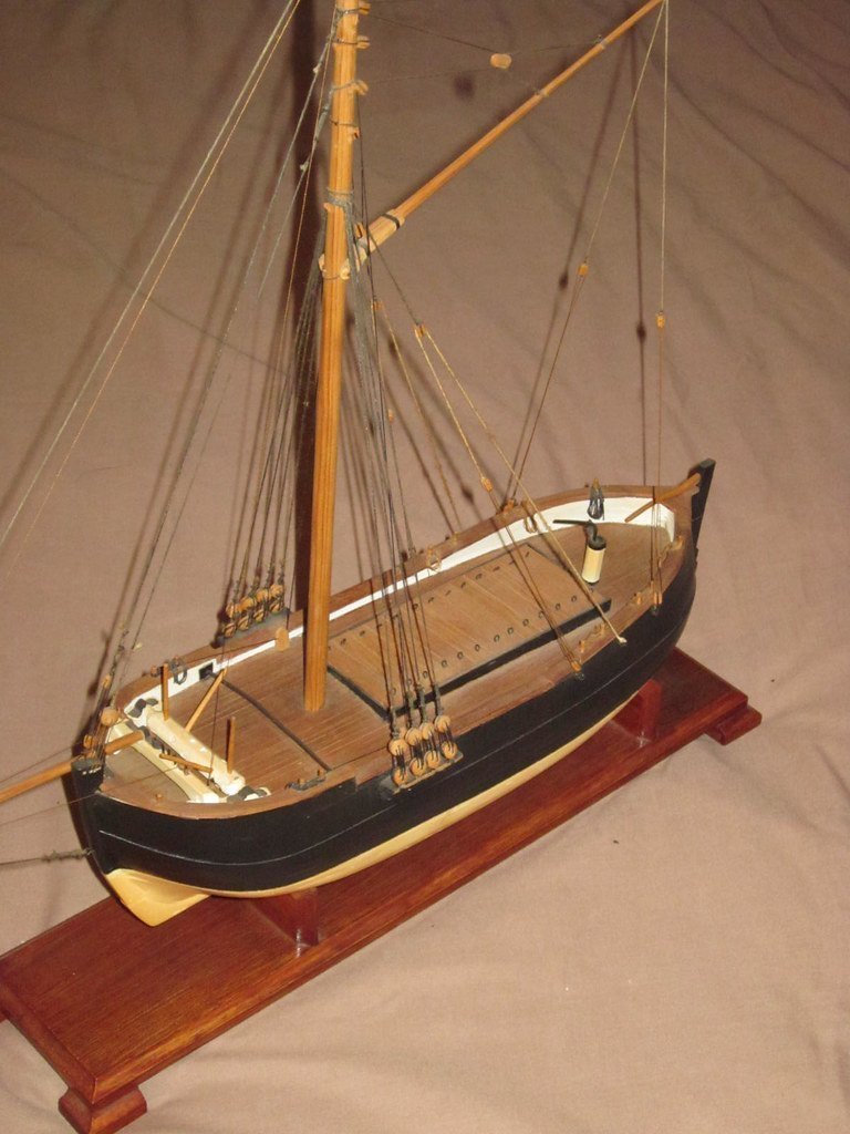
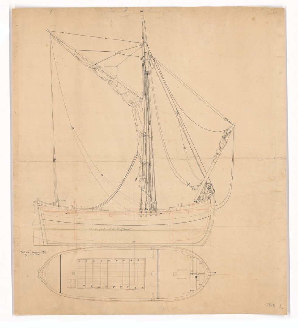
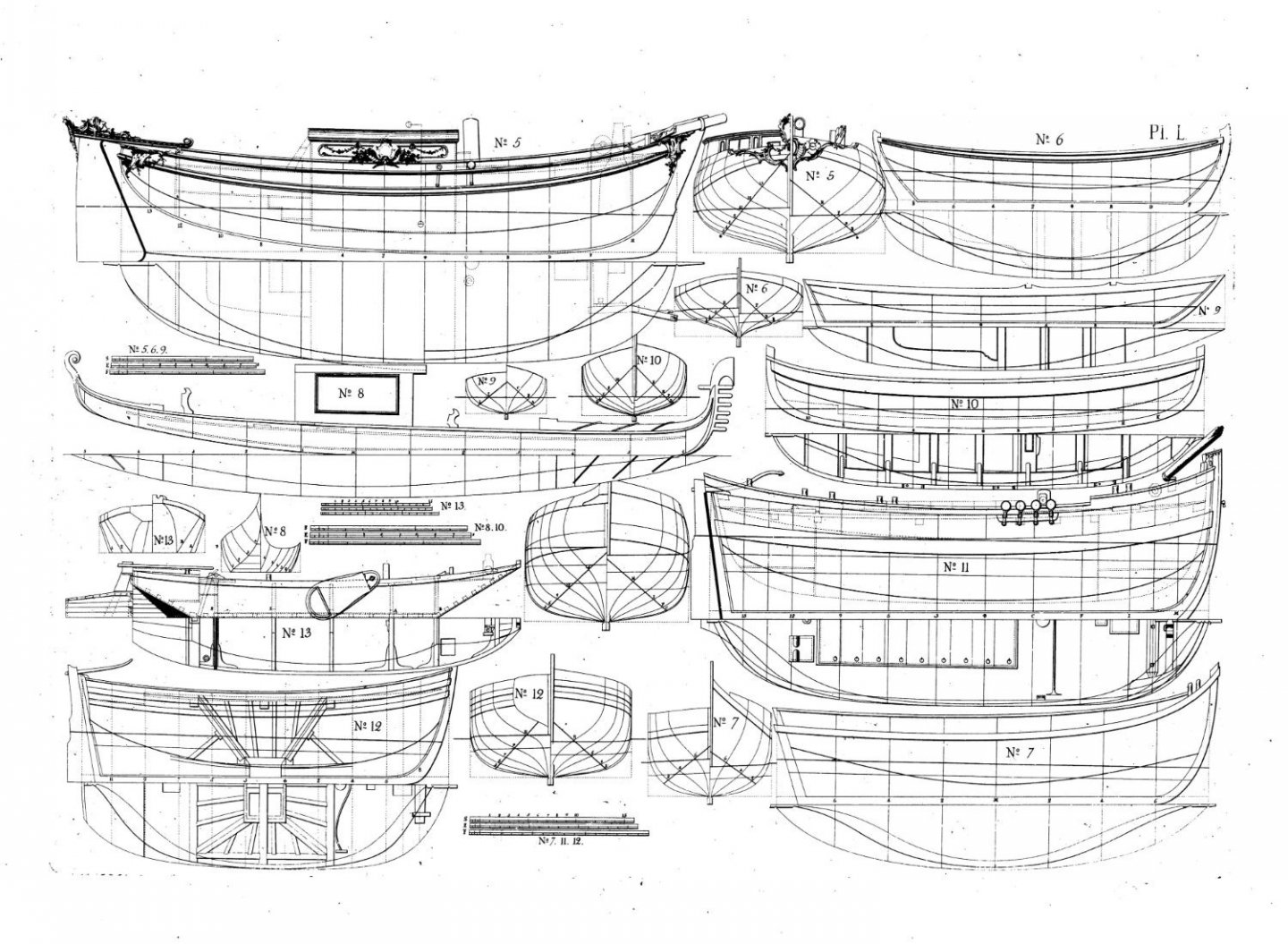
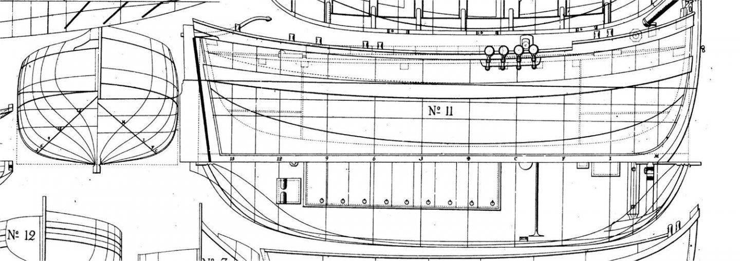
Chapman Hoy Scratch Build 1:48 scale This will be my log for a 1:48 scale (actually 1:50 scale as all the plans are metric) scratch build of a Chapman Water Hoy. A hoy is a small vessel, designed to move cargo and supplies to and from ships and the shore. These included provisions, munitions, fresh water etc. Hoys were sloop-rigged, with a mainsail on a gaff, but loose-footed (no boom). Fifty tons burthen was typical for size. This hoy had a large beam and draft for her length to maximize carrying capacity. The Chapman Water Hoy was designed by Fredrik Henrik af Chapman, a Swedish ship designer in 1768. This is an odd little ship but very interesting and with a simple rig. She was built for a life of hard work. The photos show three drawings of the vessel and a model photo i found on the internet. Another reason I chose her to build is to spare the world another "Victory" or "Syren" build log! LOL!!
- 17 replies
-
- 21
-
-
Thanks for the kind words and the “likes”!
-
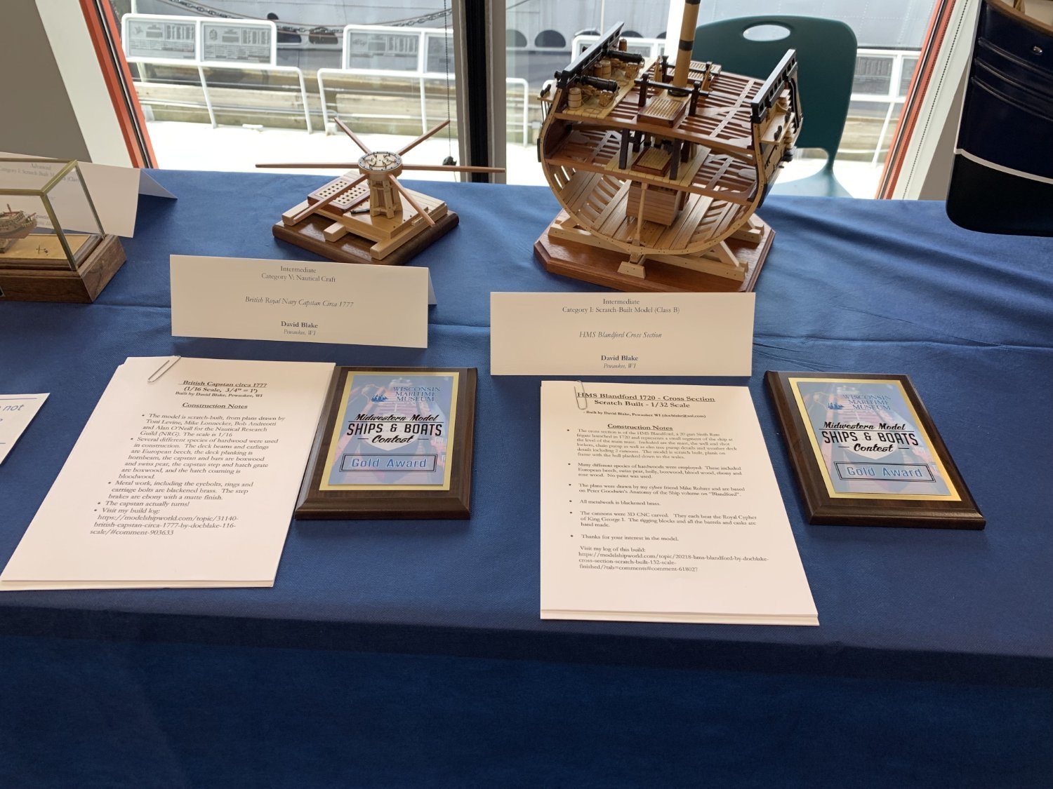
I just returned from Manitowoc WI where I attended the The 45th annual Model Ships and Boats Contest. I entered two models: The British Capstan circa 1777 and the HMS Blandford cross section. I'm pleased to report that each model won a Gold Award! Thanks to Mike Rohrer (Mike41) for his excellent plans for Blandford and to Toni Levine et.al. and the NRG for the Capstan project.

- 164 replies
-
- 12
-
-
I just returned from Manitowoc WI where I attended the The 45th annual Model Ships and Boats Contest. I entered two models: The British Capstan circa 1777 and the HMS Blandford cross section. I'm pleased to report that each model won a Gold Award! Thanks to Mike Rohrer (Mike41) for his excellent plans for Blandford and to Toni Levine et.al. and the NRG for the Capstan project.