DocBlake
-
Posts
1,811 -
Joined
-
Last visited
Content Type
Profiles
Forums
Gallery
Events
Everything posted by DocBlake
-
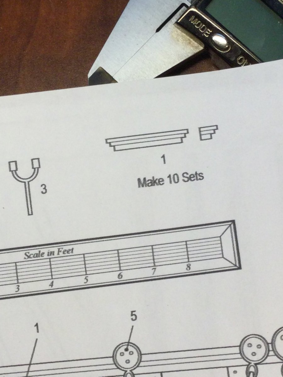
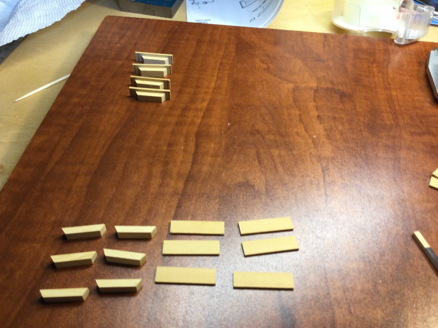
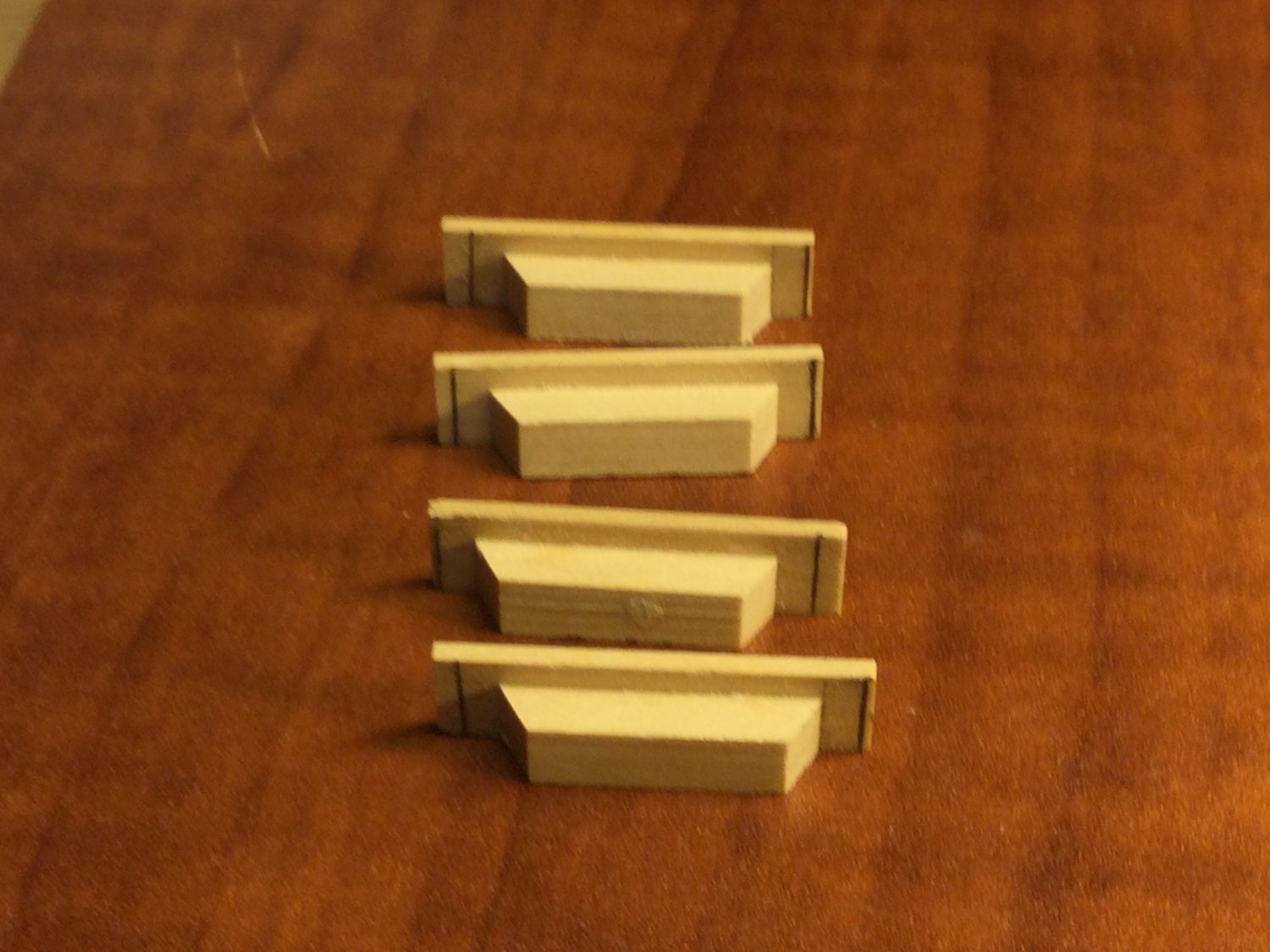
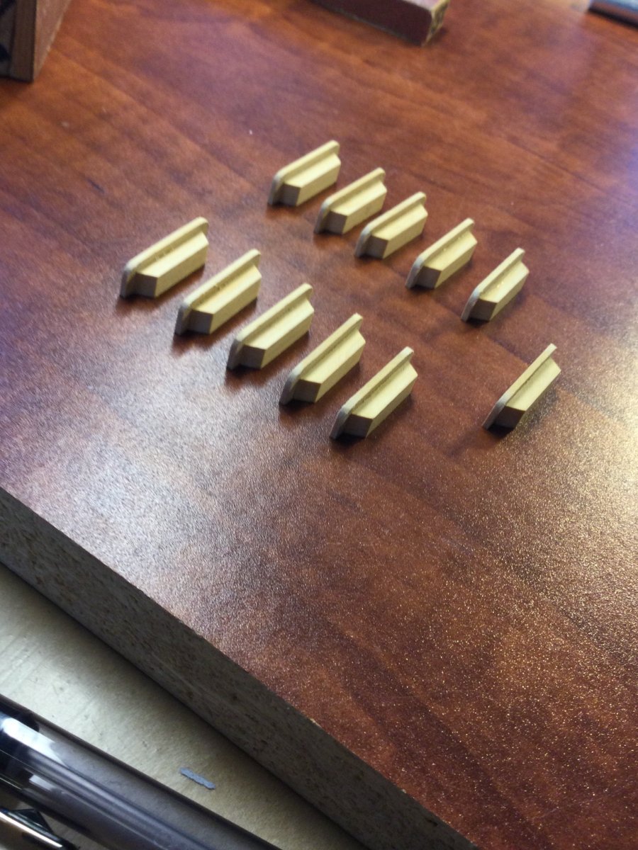
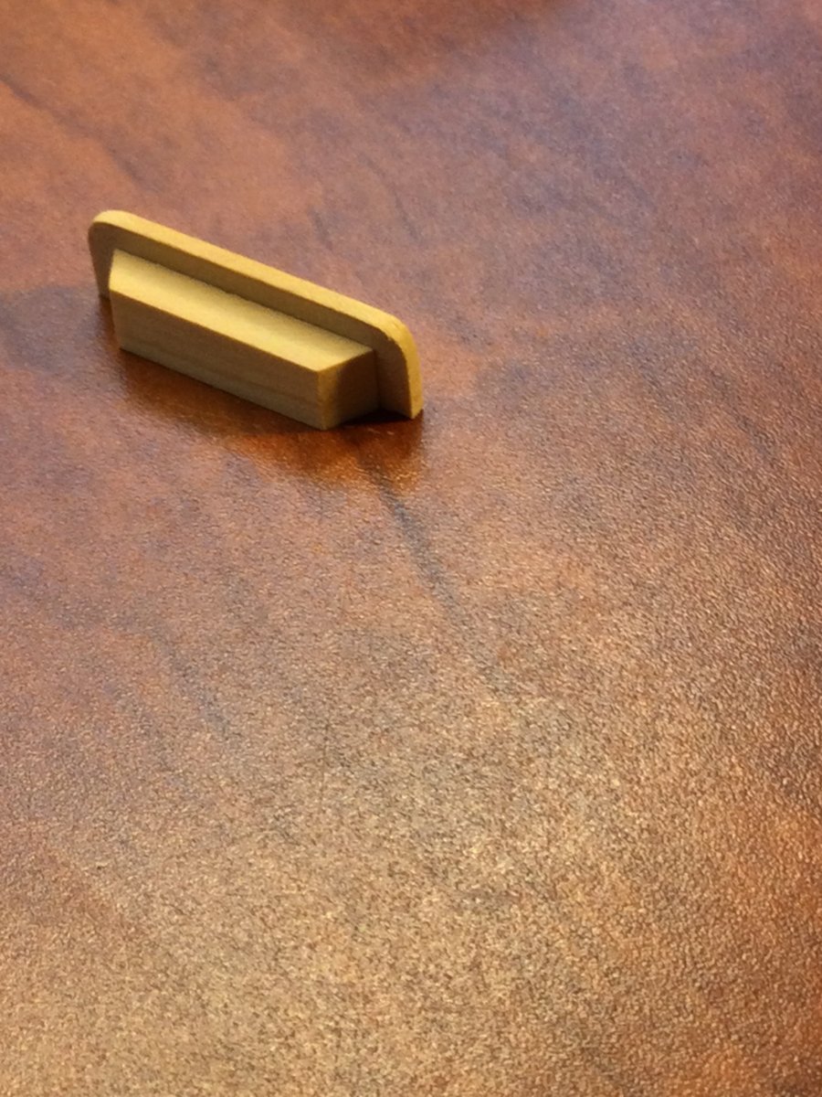
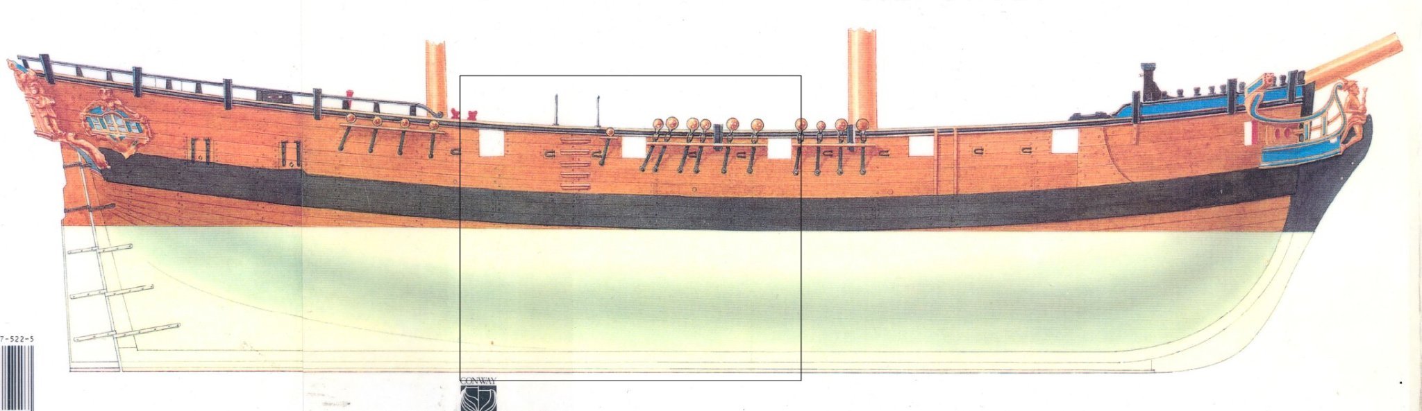
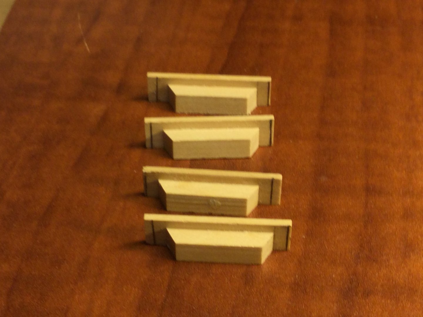
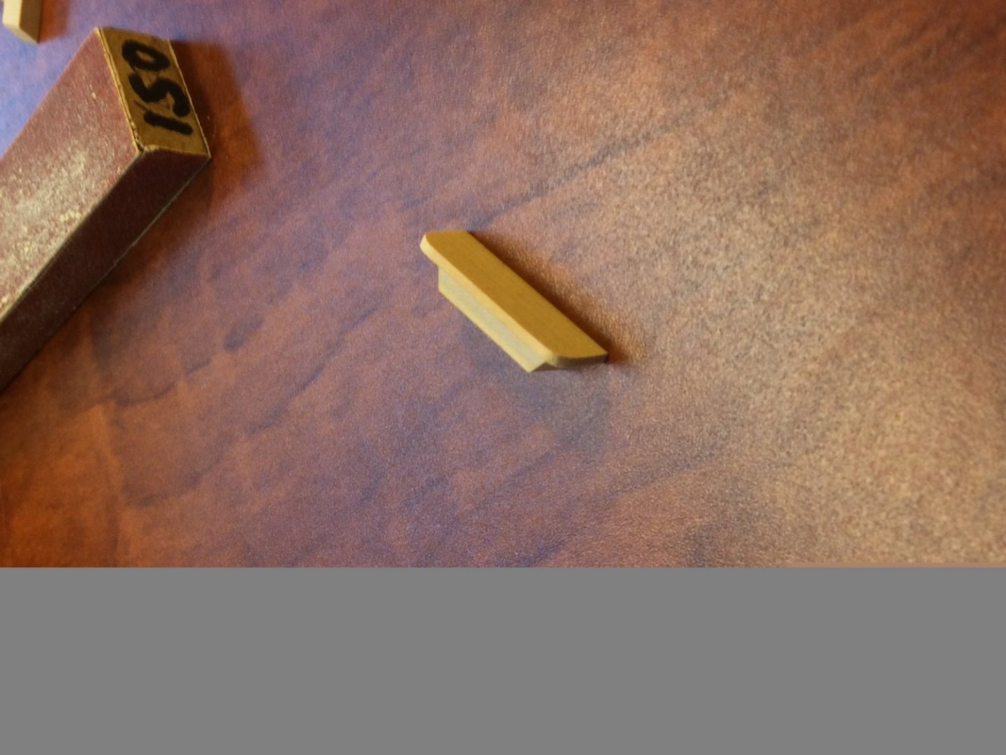
 I have been spending some time building the removable pit housing for the mortar pit. This was a removable structure that protected the mortar from the weather when not in use and also provided protected storage space. As I worked, I realized that the housing would obscure too much detail on the mortar and bed, so I decided to stop construction and move on to something else. The boarding steps in Jeff Staudt's plans are cut from a single piece of wood, and I didn't really care much for the design, so I used my own design! The treads are 3/64" thick boxwood and the risers are 7/64" boxwood. The ends of the risers are cut at a 60 degree angle and the tread overhangs the riser on three sides. Rather than try to glue the treads to the risers and get the overhangs perfect, I left the treads oversized when I glued up each step. I then marked them to the proper length and "cut" them to size using the disk sander. Rounding the tread corners finished the job. There are 5 steps per side.
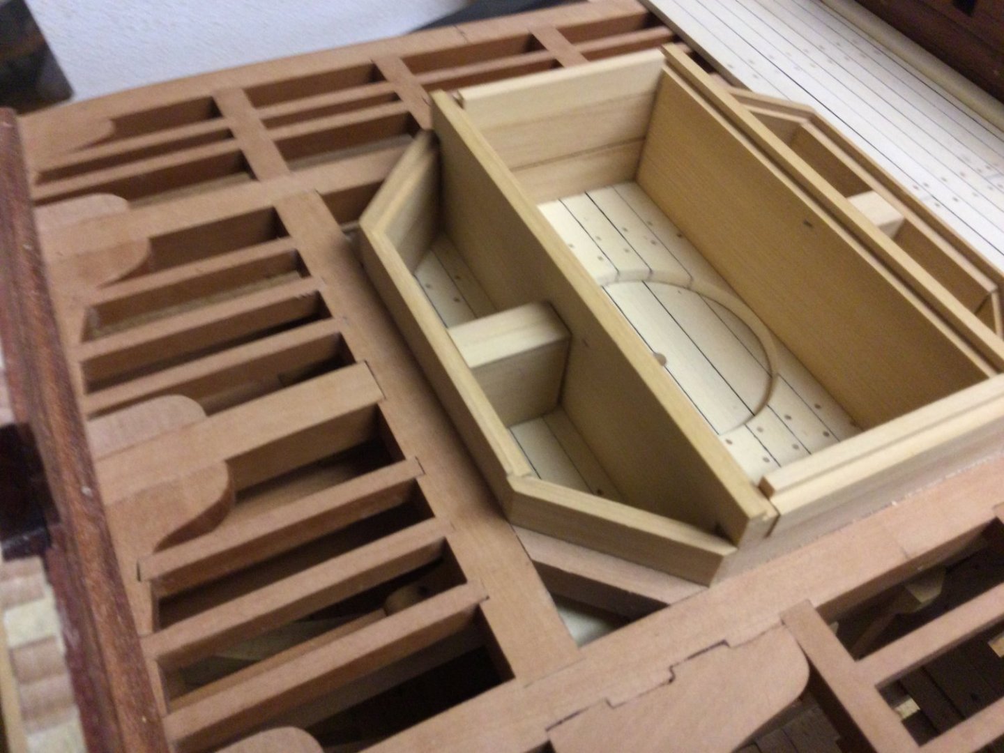


- 143 replies
-
- 16
-

-
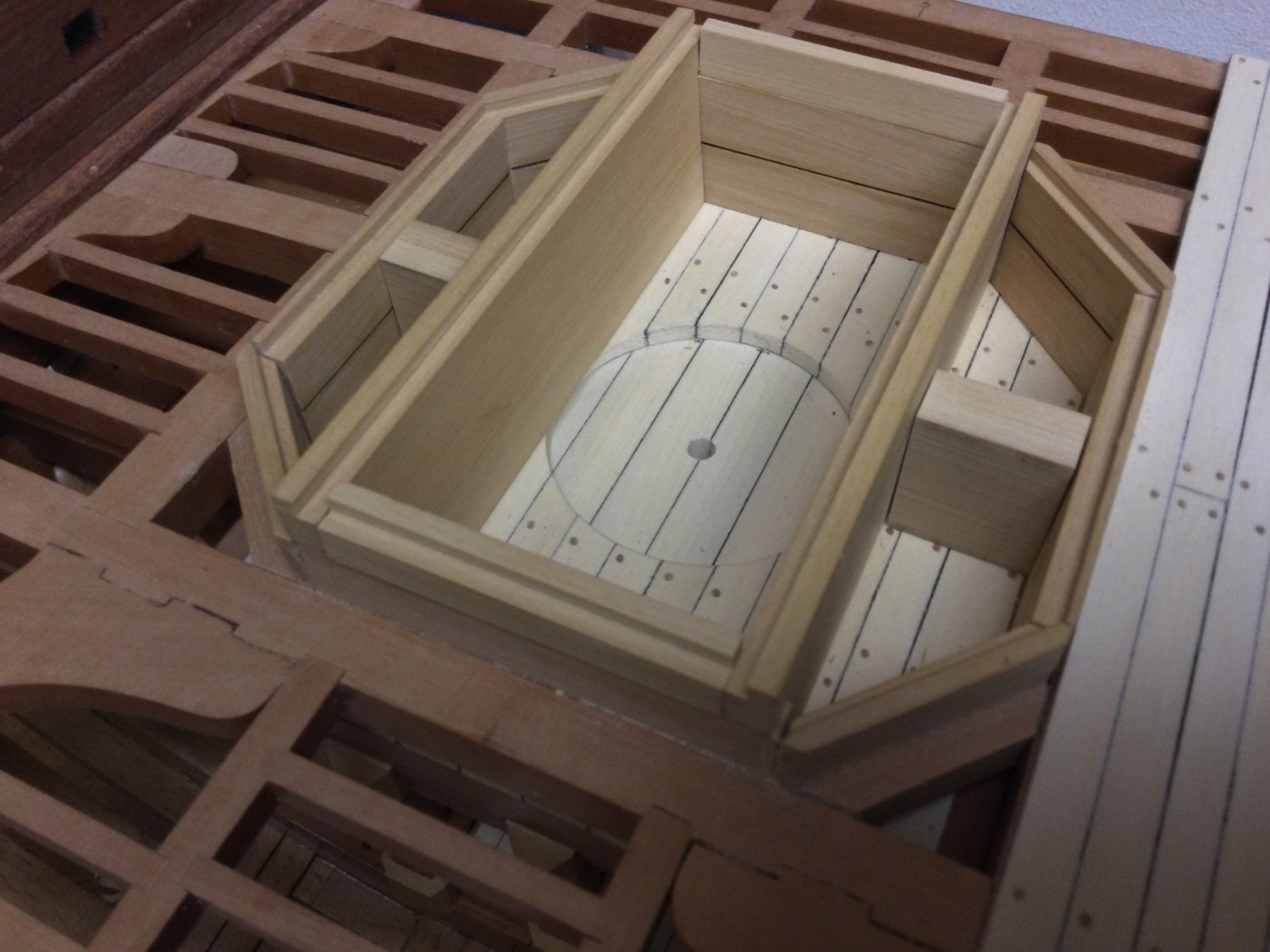
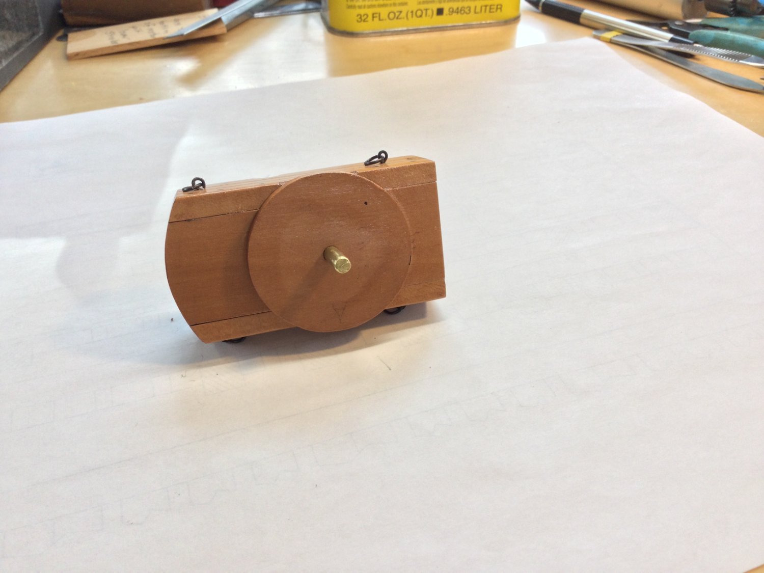
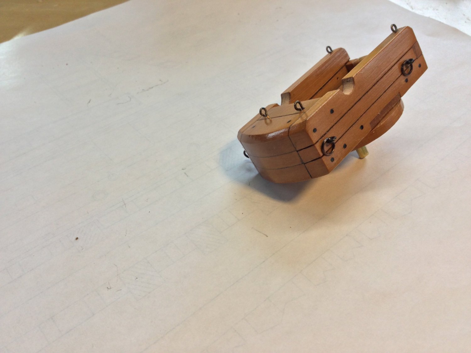
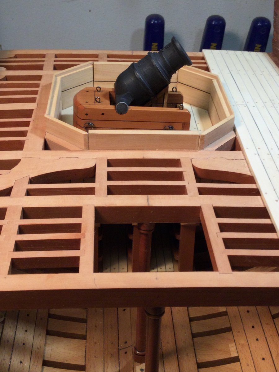
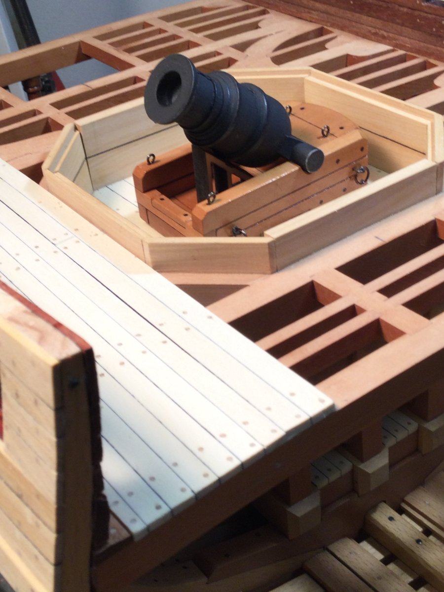
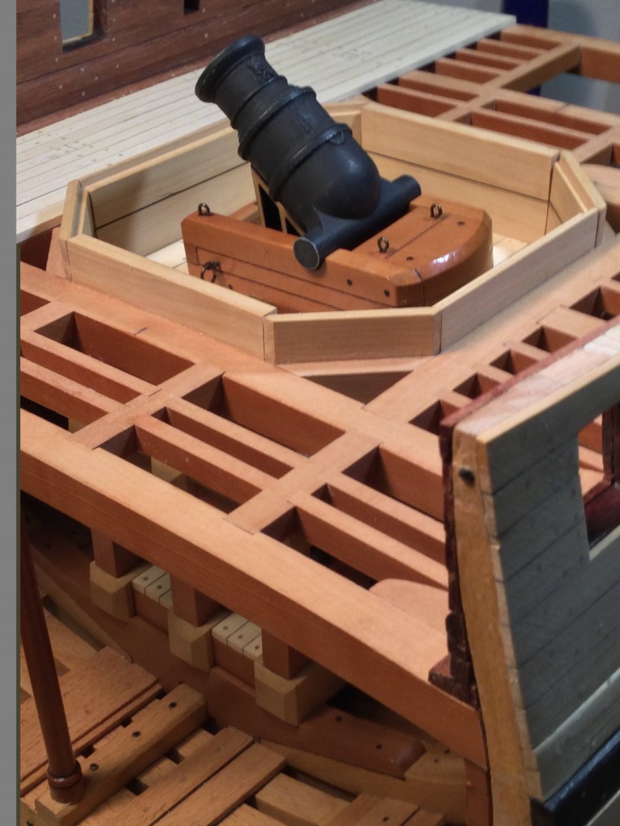
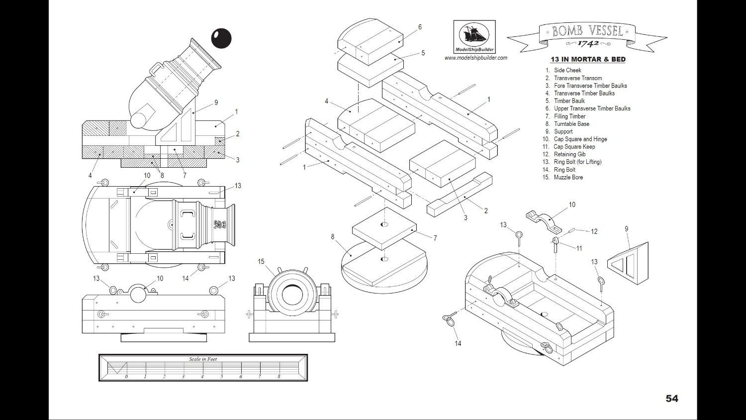
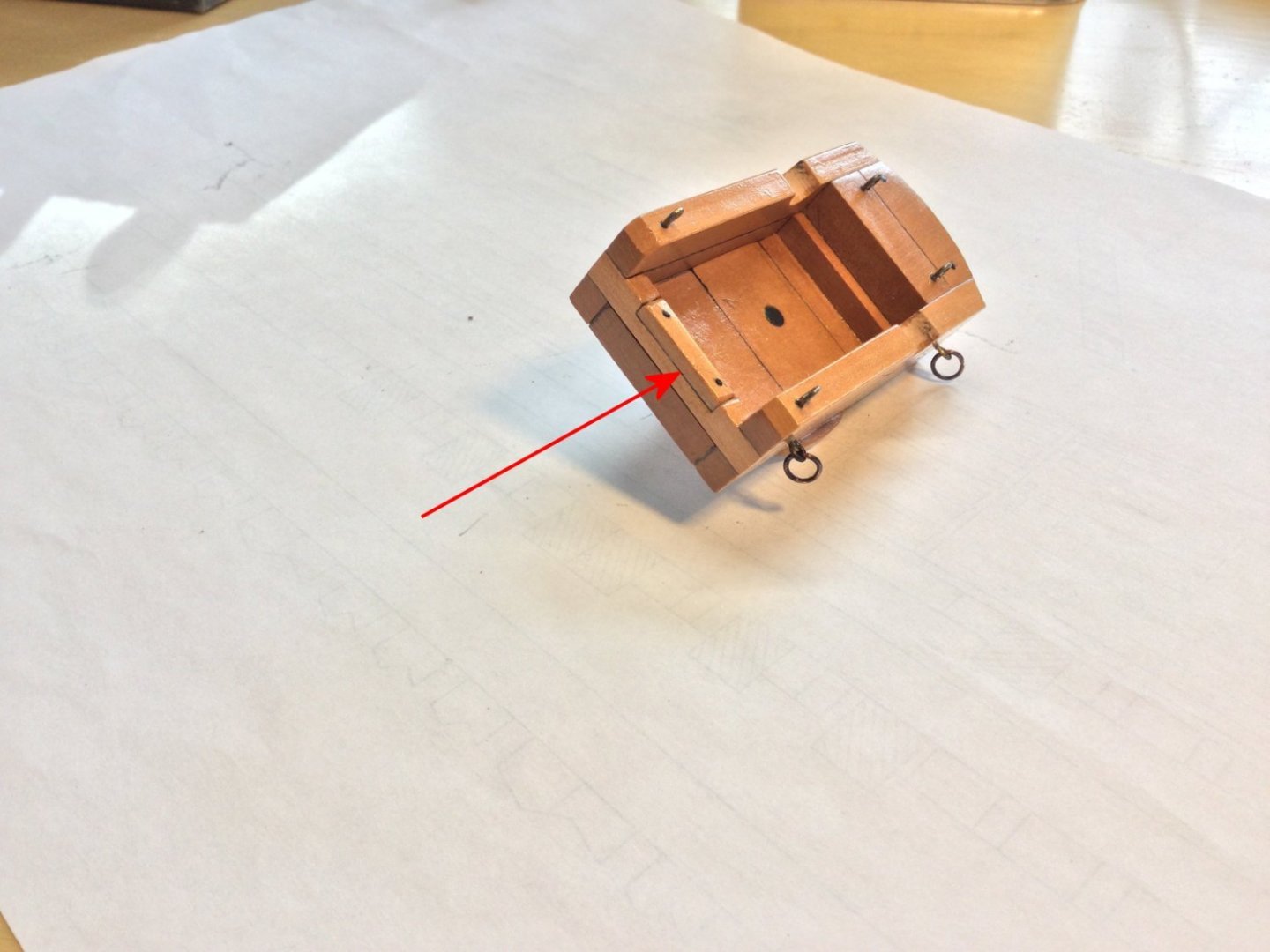
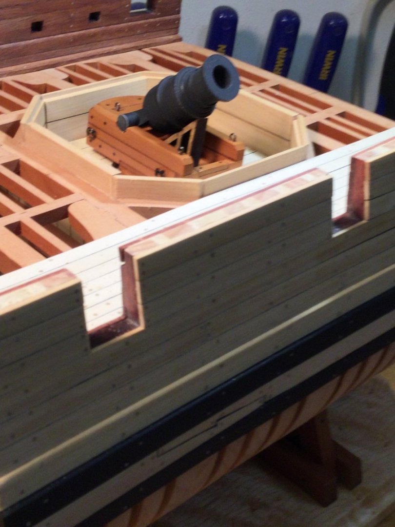
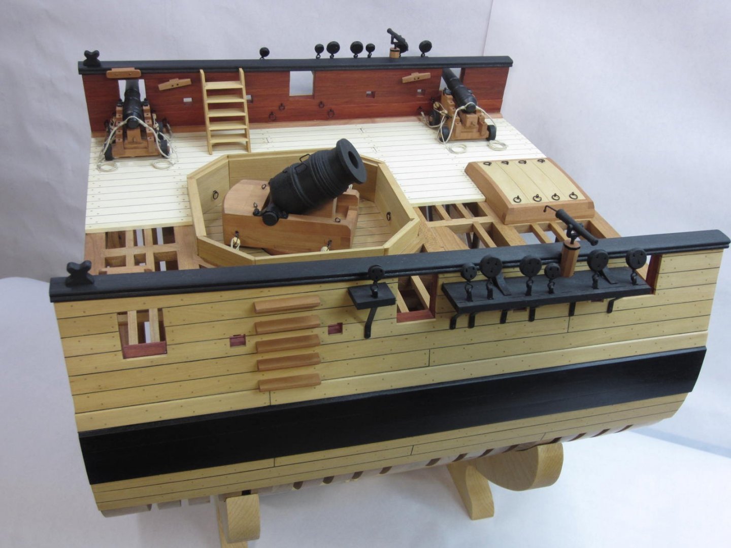
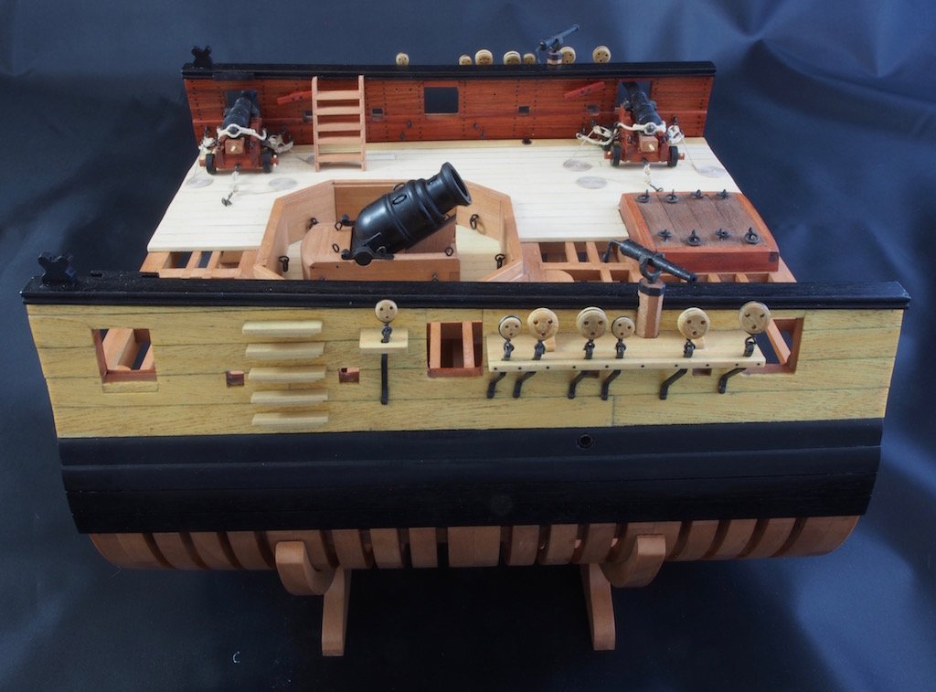
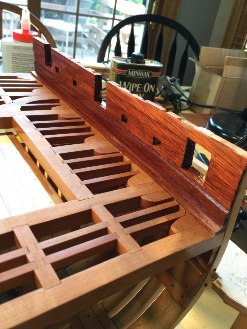
Thanks, Pat and everyone for the "likes! I finished up the mortar bed. It was a complex little build that took several days, but was a fun project on it's own. The varying thicknesses of wood that needed to be milled and when stacked on each other so the top of the bed was flat called for a lot of precision and caused lots of heartburn! But..it's done! Mortar beds were originally stationary on deck, so to aim, the ship needed to move such that the mortar lined up with it's target. Not very practical. The solution was to put the bed on a revolving "lazy susan" that sits in the recess in the mortar pit. The rotation was around an iron spindle, shown in the photos as a 5/32" brass rod. This allowed greater ease of aiming, but made it necessary to pay attention so one didn't shoot the masts, yards and rigging of one's own ship! When not in use, the mortar was lowered into the horizontal position resting on the transom of the bed, and the entire bed was rotated so the mortar was aligned with the long axis of the ship. Because of the wear and tear the mortar barrel would cause resting on the top of the transom, I added a sacrificial transom board to the top that could be replaced if needed. Sort of like billboards for the anchors. The red arrow points this out. The mortar is 3D printed. I'll be using a cast mortar for the model. Next up is the mortar housing.


- 143 replies
-
- 18
-
-

-
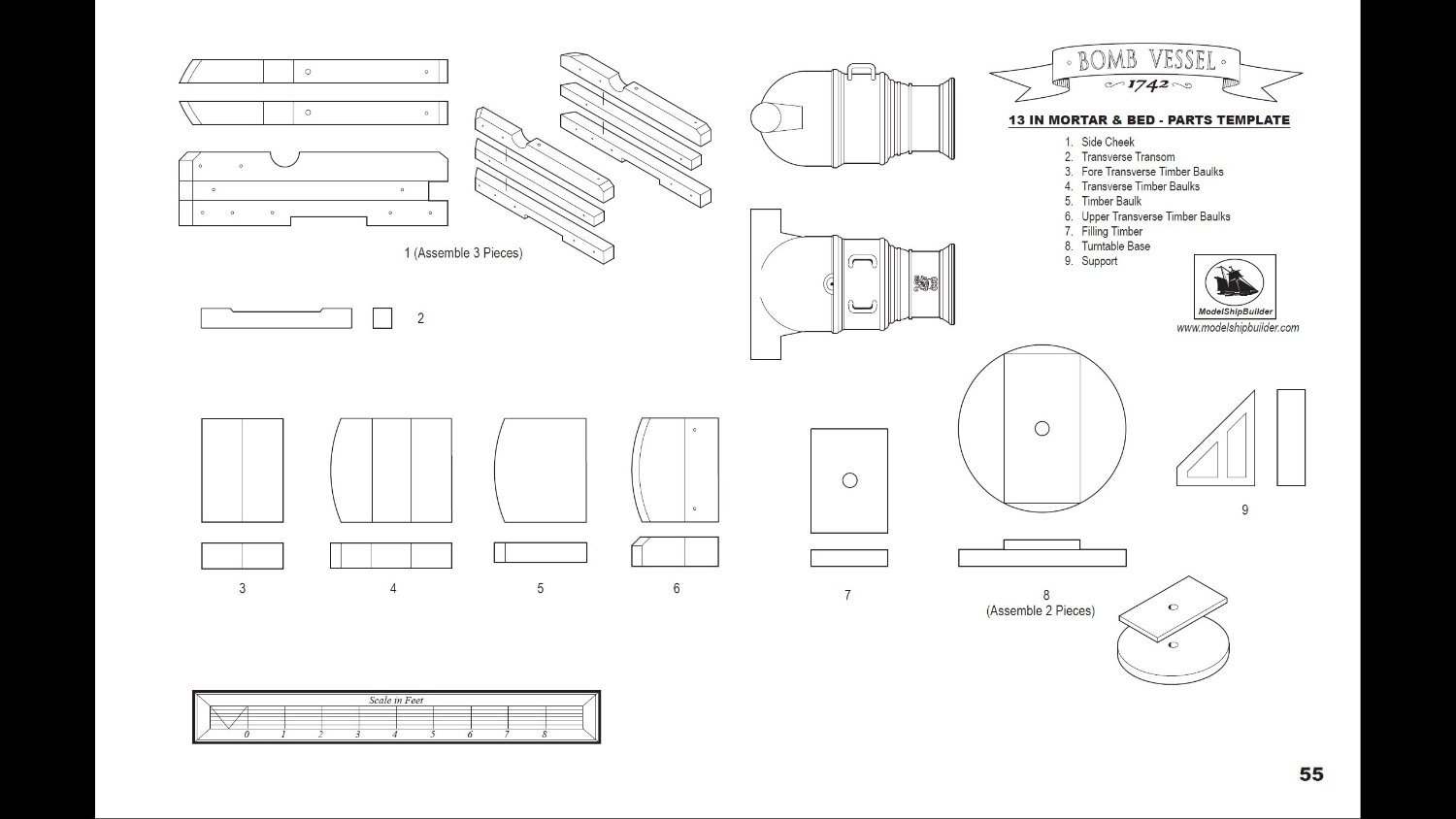
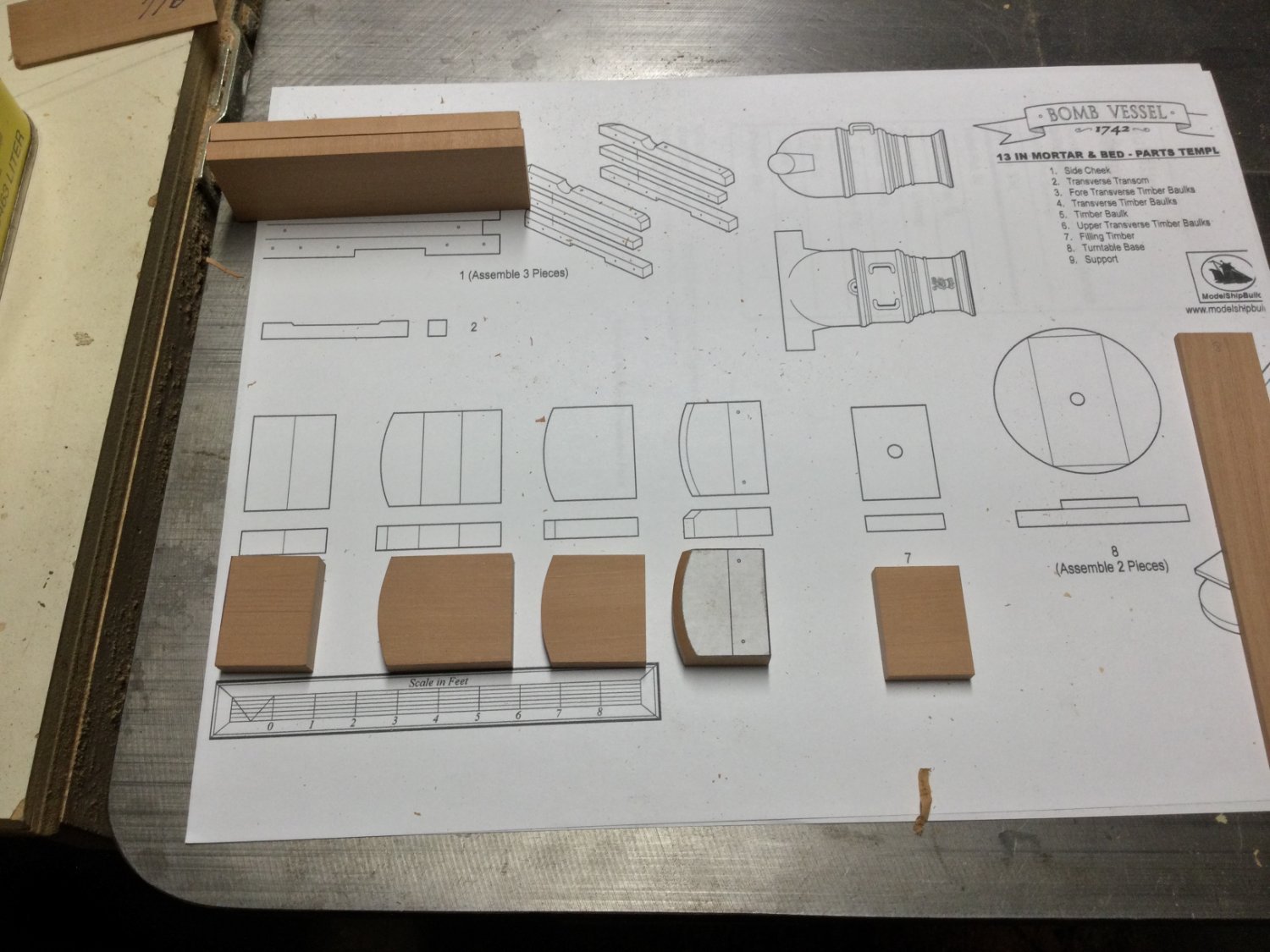
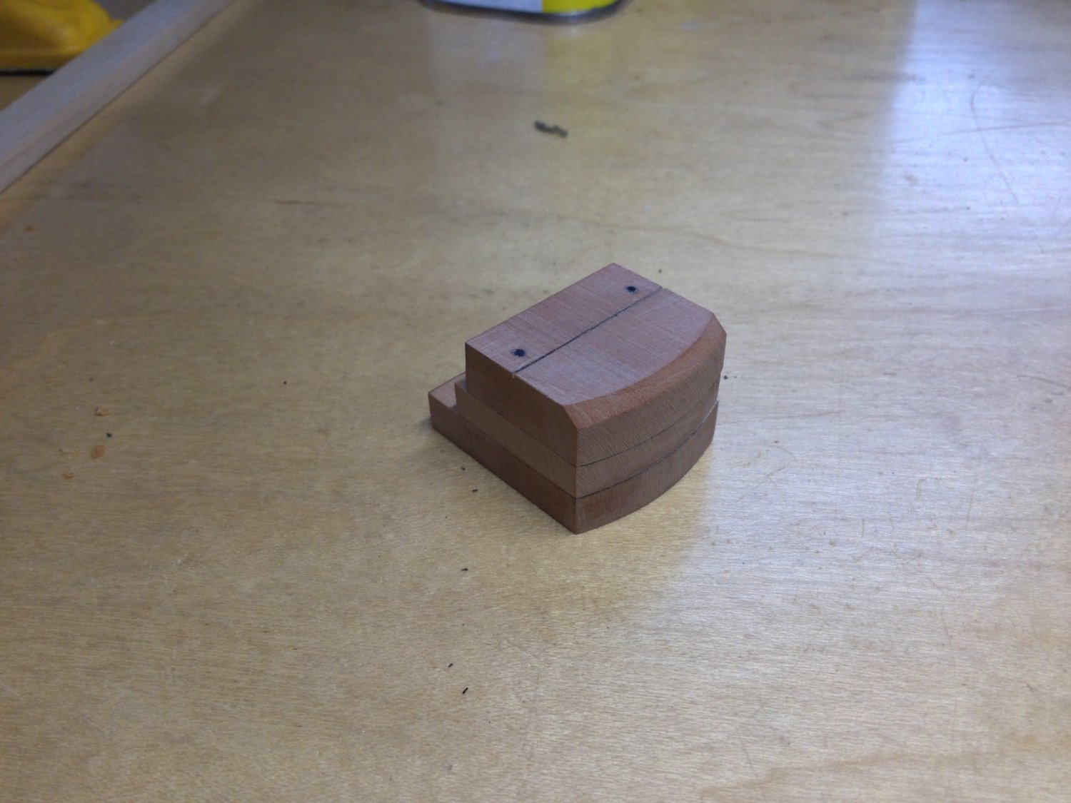
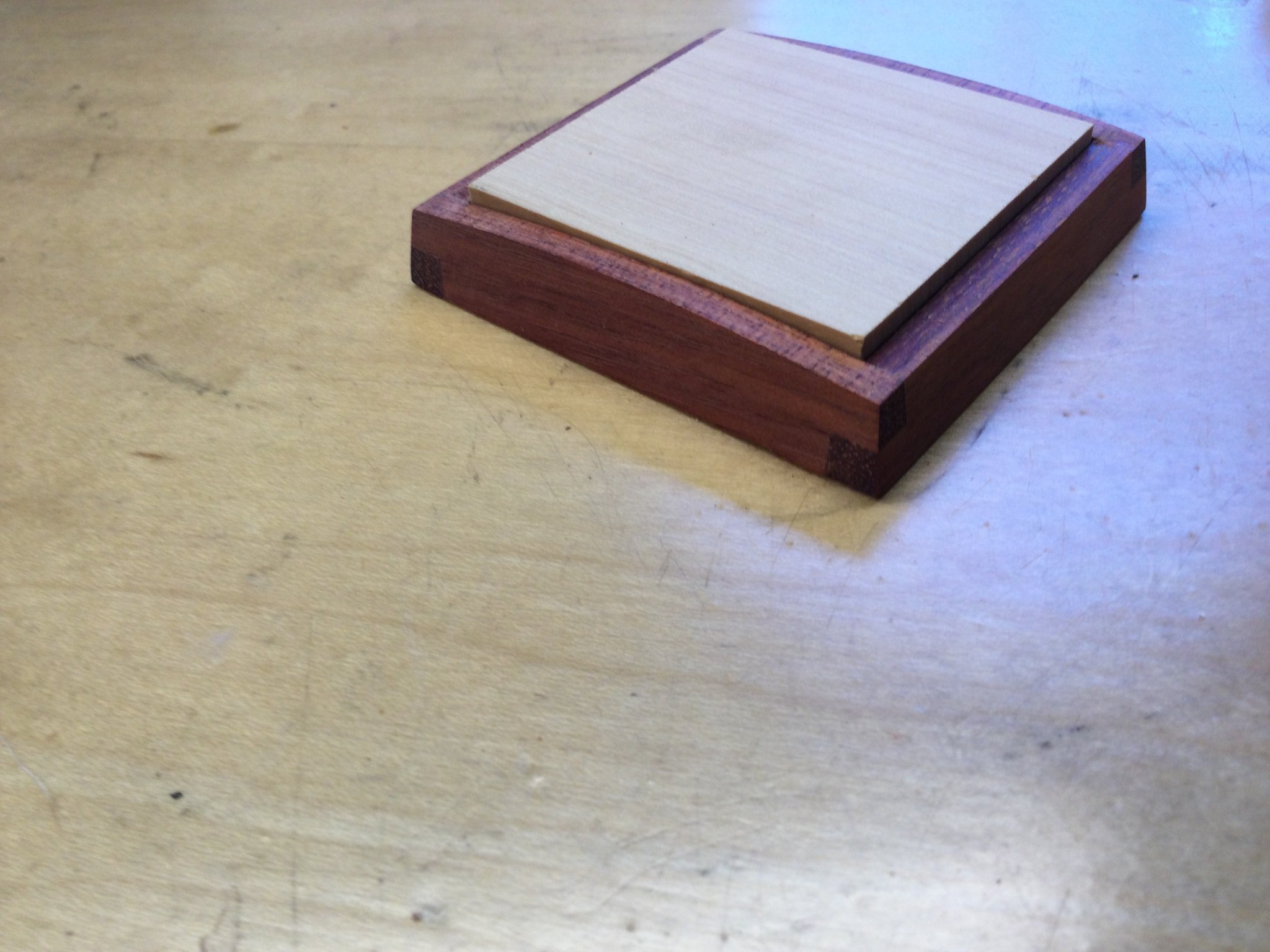
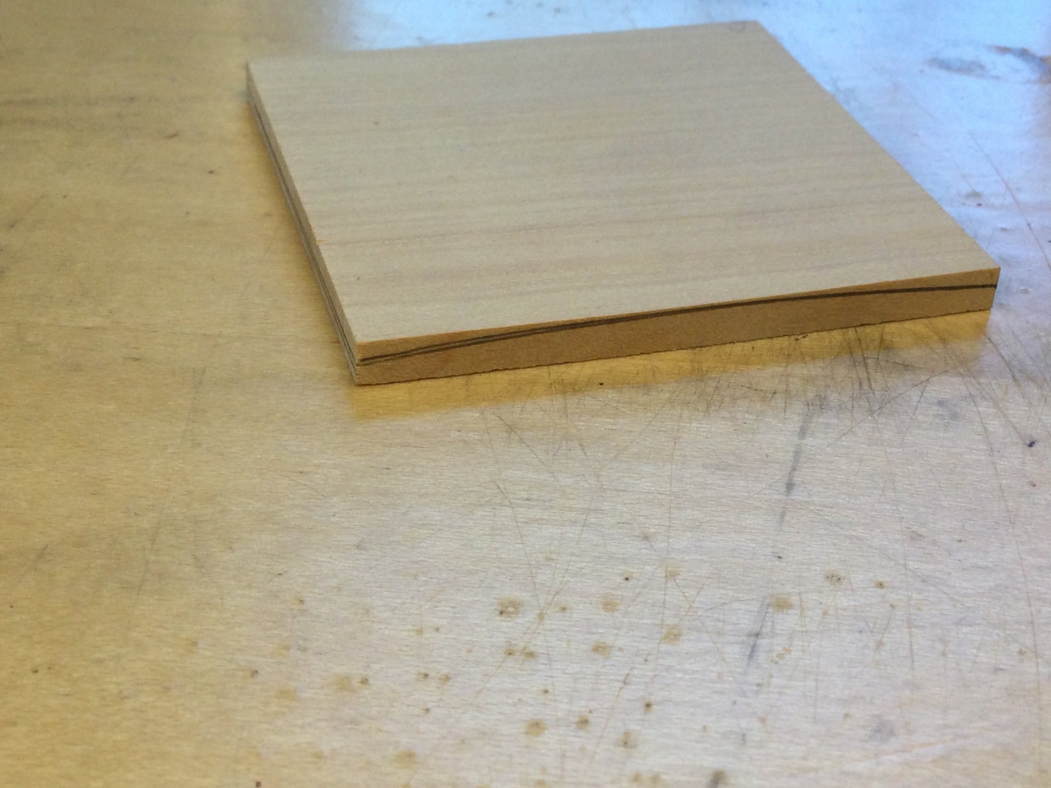
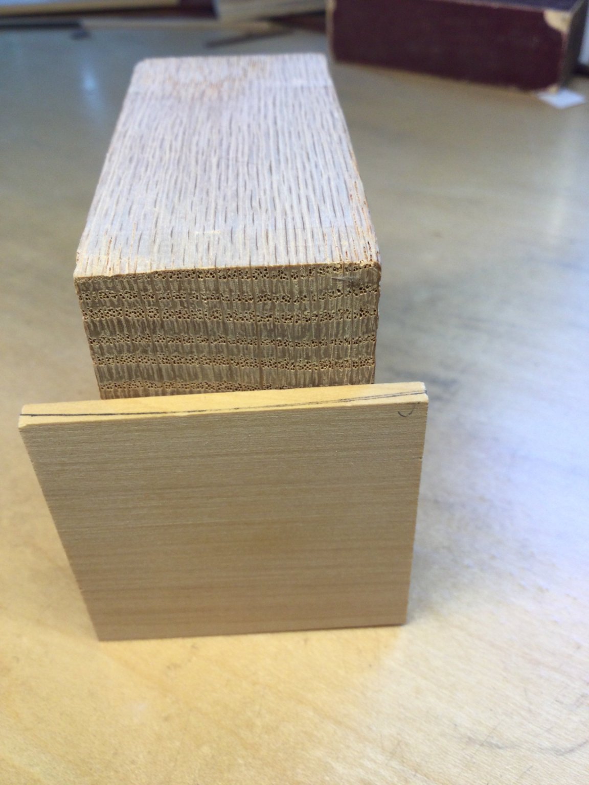
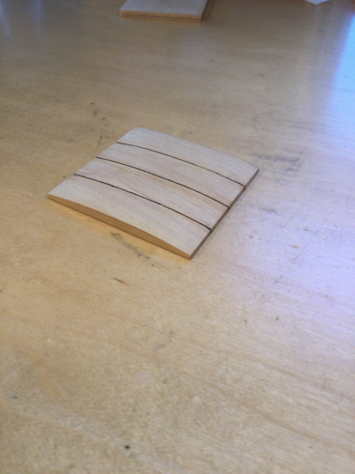
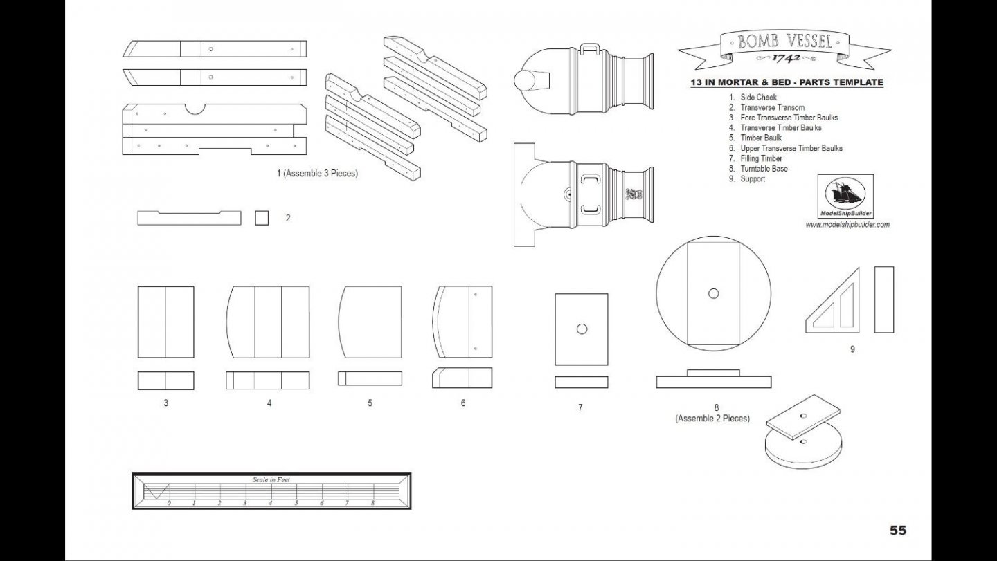
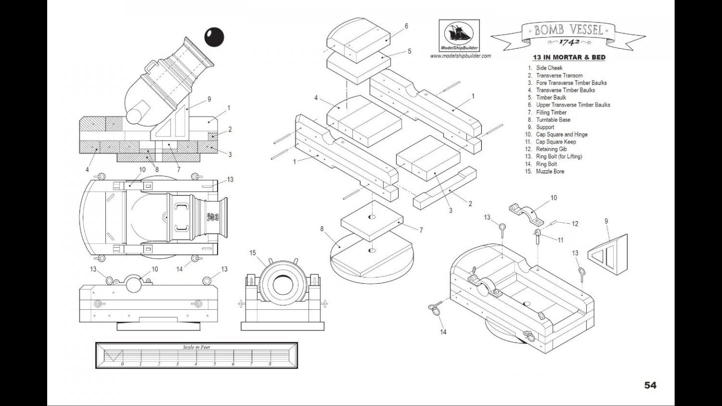
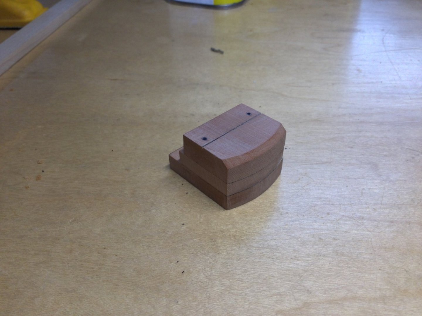
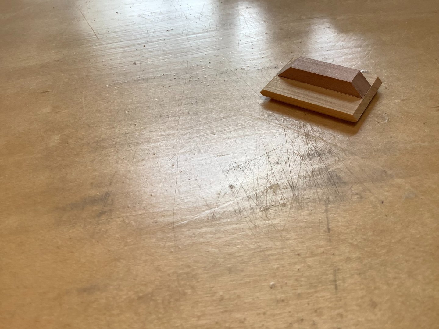
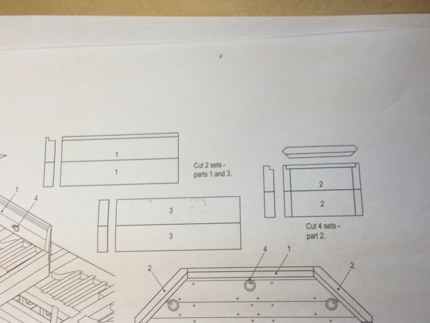
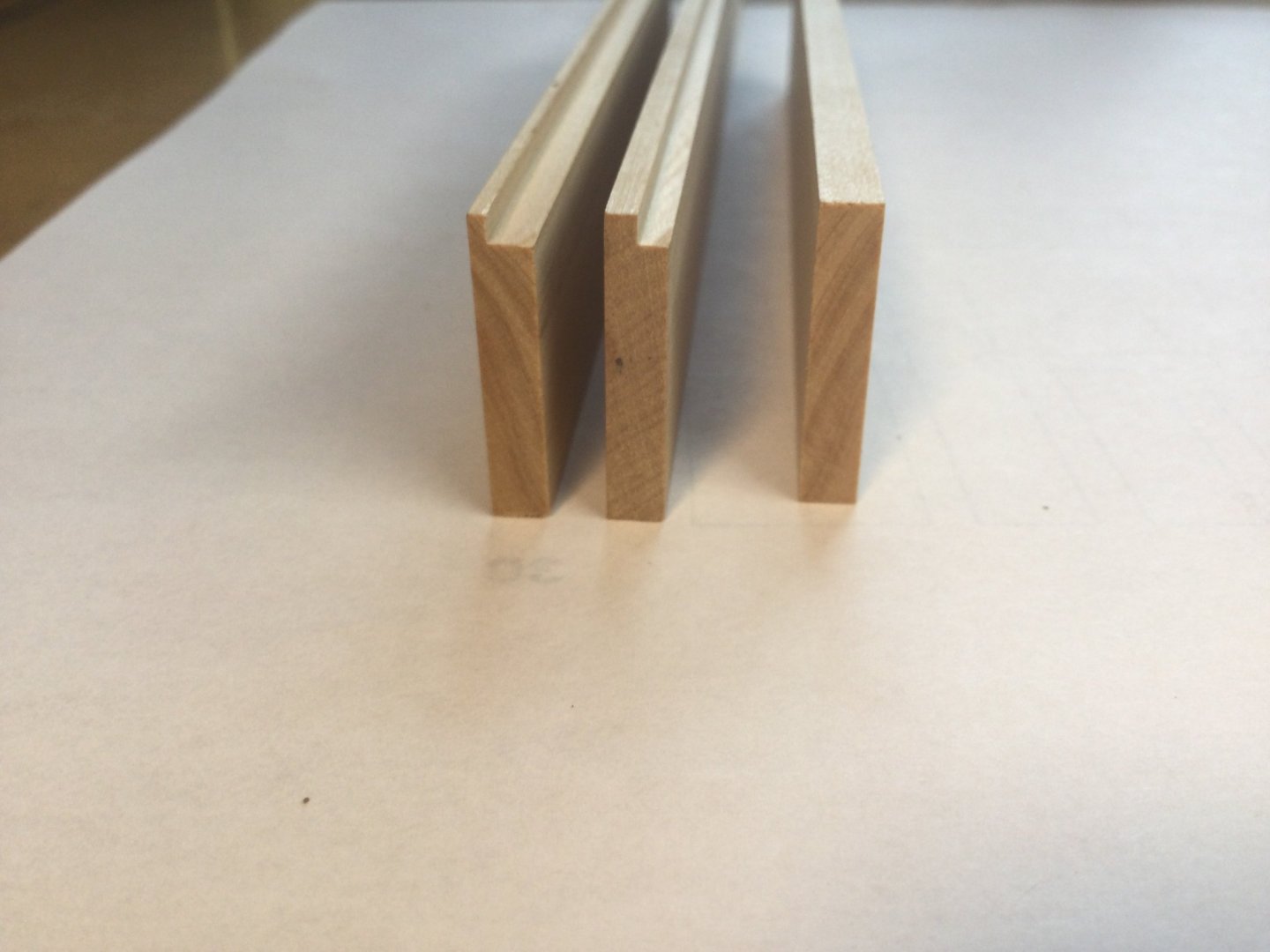
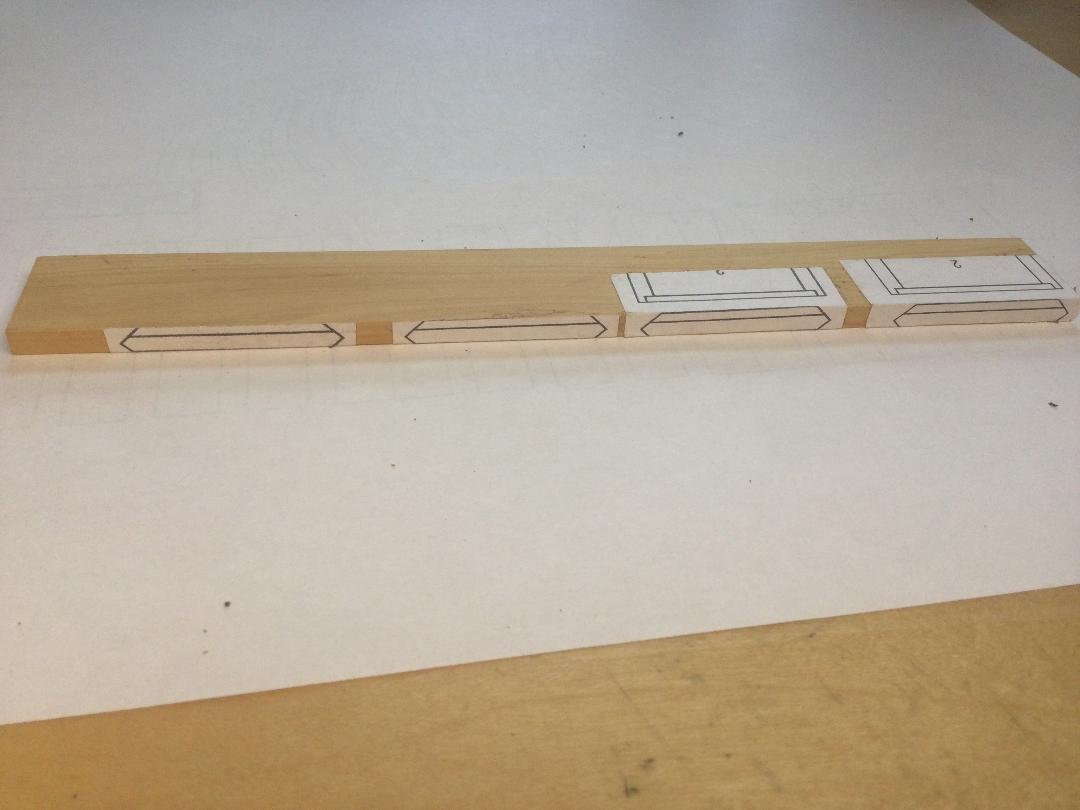
Thanks, guys! It's been a busy couple of months! We're redoing the flooring in two bedrooms in the house so I had to remove carpeting and underlayment to prep for hardwood floor installations. Lots of work. Also painted the entire downstairs of the house as well as those two bedrooms. To reward ourselves, Liz and I took the family to St. Martin FWI for a well needed vacation. Our first trip back in nearly 2 years. It felt great. Now my consulting work is ramping up, keeping me busy, but I'm committed to getting back to the workbench! I began work on the mortar bed. To look at a finished bed, it doesn't lookappear too challenging. I'm coming to discover that it is the most difficult part of this build by far! There are 19 parts comprising the bed as shown on the plans, not including the iron support and the mortar itself. The first problem is dimensions. Almost of these parts are different thicknesses, but must result in a bed that is uniform in height and width. The second problem is the scale. At 1:32 the lines comprising the plan drawings have a fair amount of thickness to them. So depending on where you measure, you possibly have variation of up to 1/32" to 3/64". The layout and cutting parts is slow, tedious, precise work that took a good number of hours. The first step was to cut out the component parts. The rear part of the bed is made of three stacked parts, all curved. The top one has a 45 degree bevel cut into it. The photos show the plans, the component parts and the three slice stacked piece with the curved, beveled surface facing the rear. The wood is swiss pear.

- 143 replies
-
- 14
-
-
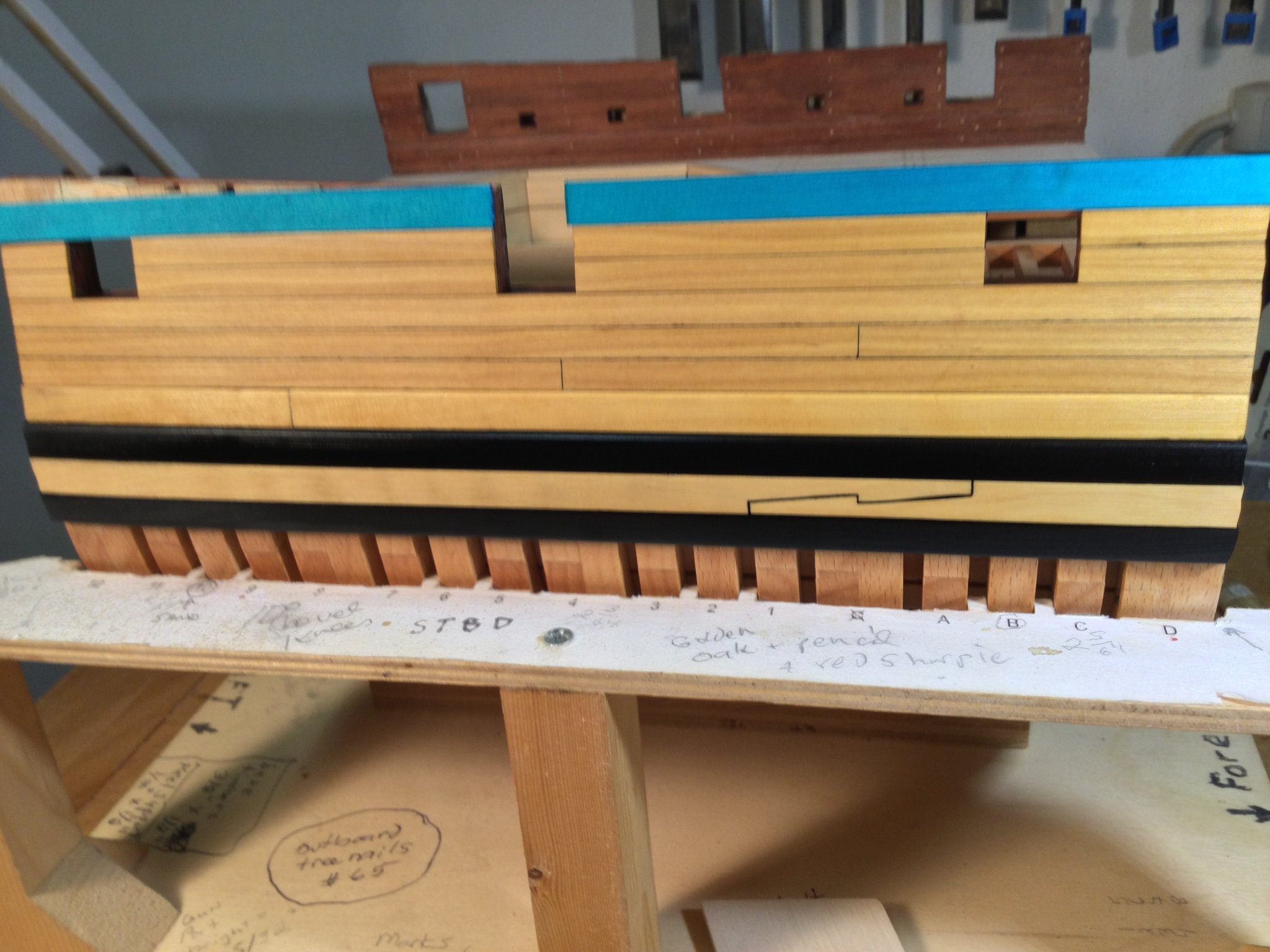
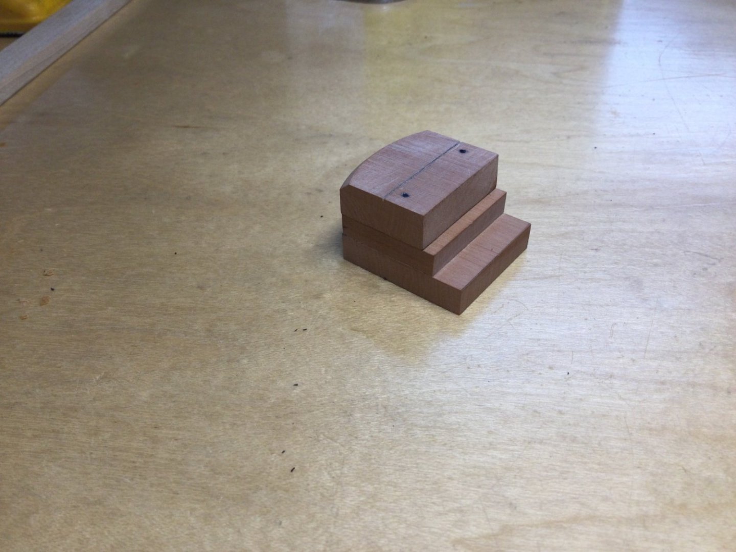
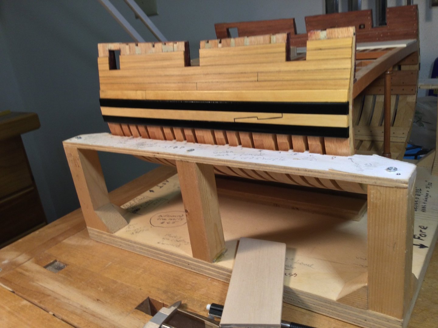
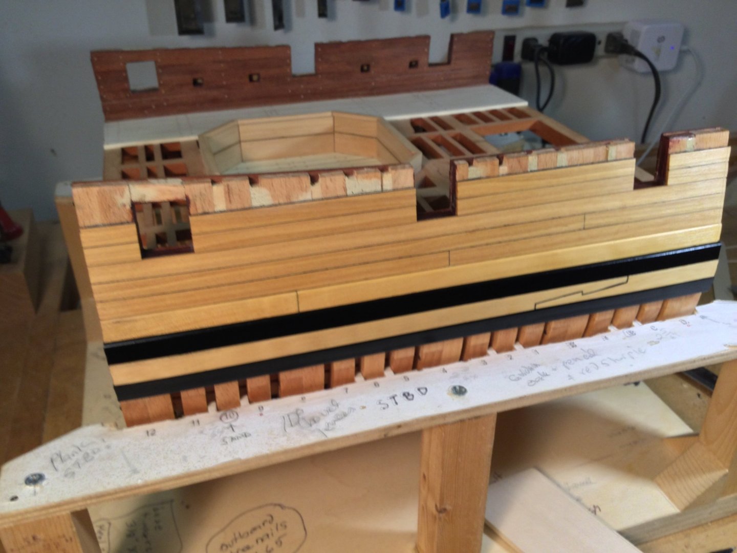
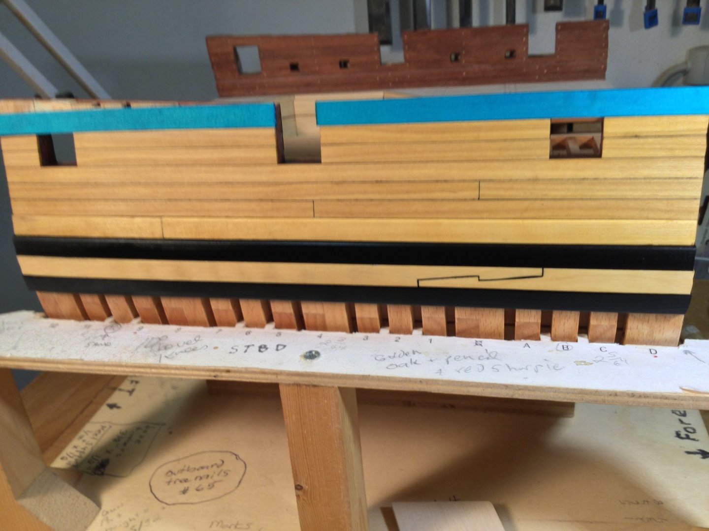
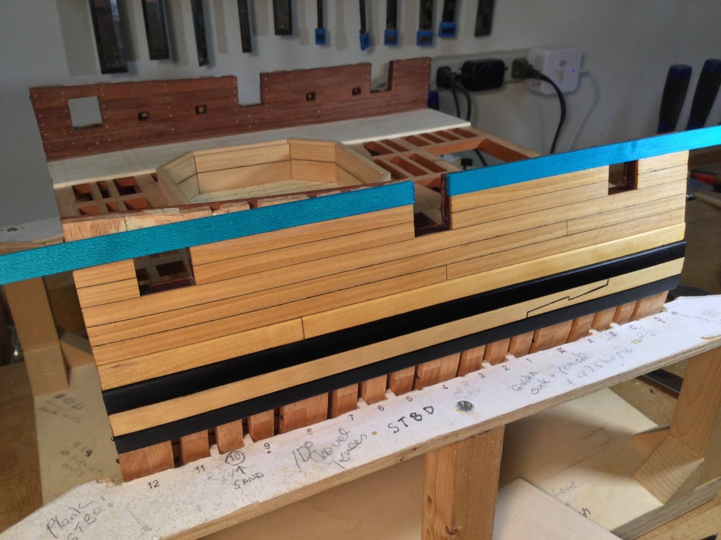
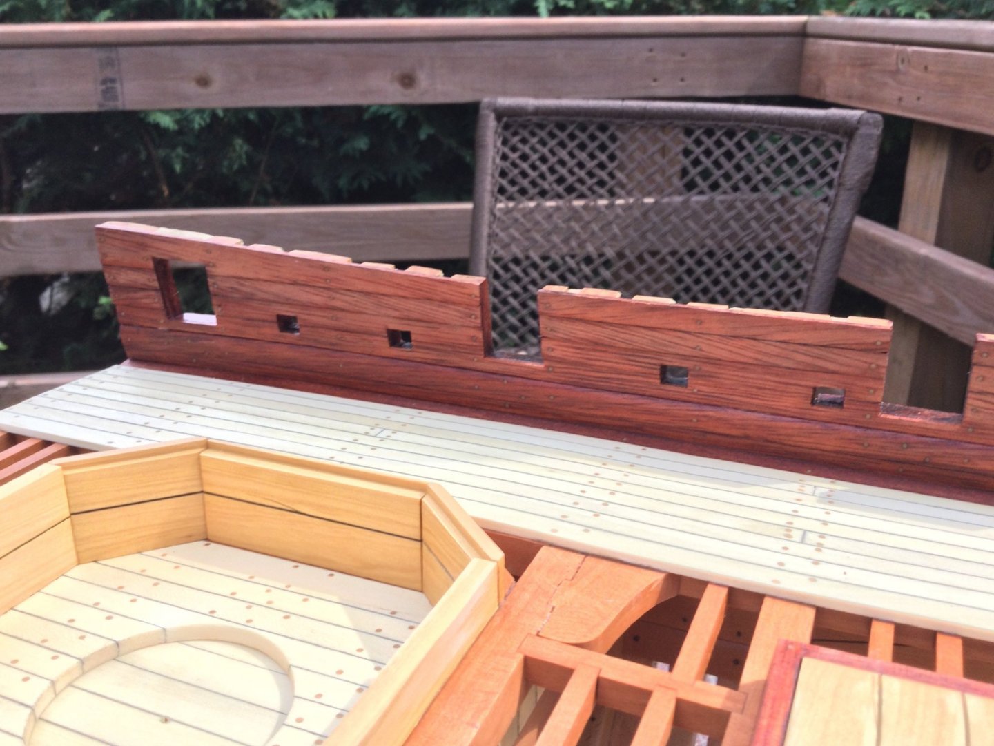
Thanks for your input, guys! I made a decision! I finished planking the bulwarks except for the plank sheers. This was done in boxwood, including the black strake. The upper and lowers wales are ebony. I chose to make the center "filling wale" out of boxwood for the contrast. In the AOTS series, both HMS Blandford and Royal Yacht Caroline have this arrangement for the wales. I decided not to use hooked scarf joint on the ebony wales since they wouldn't show up well. The filling wale joints are typically butt joints but I took some license and made a couple of hook scarfs: one on each side. I cut some holly planking and dyed it an aqua/turquoise blue. I used Transfast water soluble dye so I could glue the planks without worrying if the glue would hold. Do you guys like the look, or is it "too much" for a natural wood model? I'm not committed to anything yet. Those planks are just sitting there!
- 143 replies
-
- 14
-
-
-
I've got a dilemma. The outboard planking on Granado will be boxwood, and the 3 strakes of the wales will be ebony. The question is, how do I handle the "black strake", directly above the wale. The name suggests it should be ebony also, but the AOTS cover illustration clearly shows it to be ochre colored. Modelers have gone both ways. What do you all think? Ebony or boxwood for the "black strake"?

-
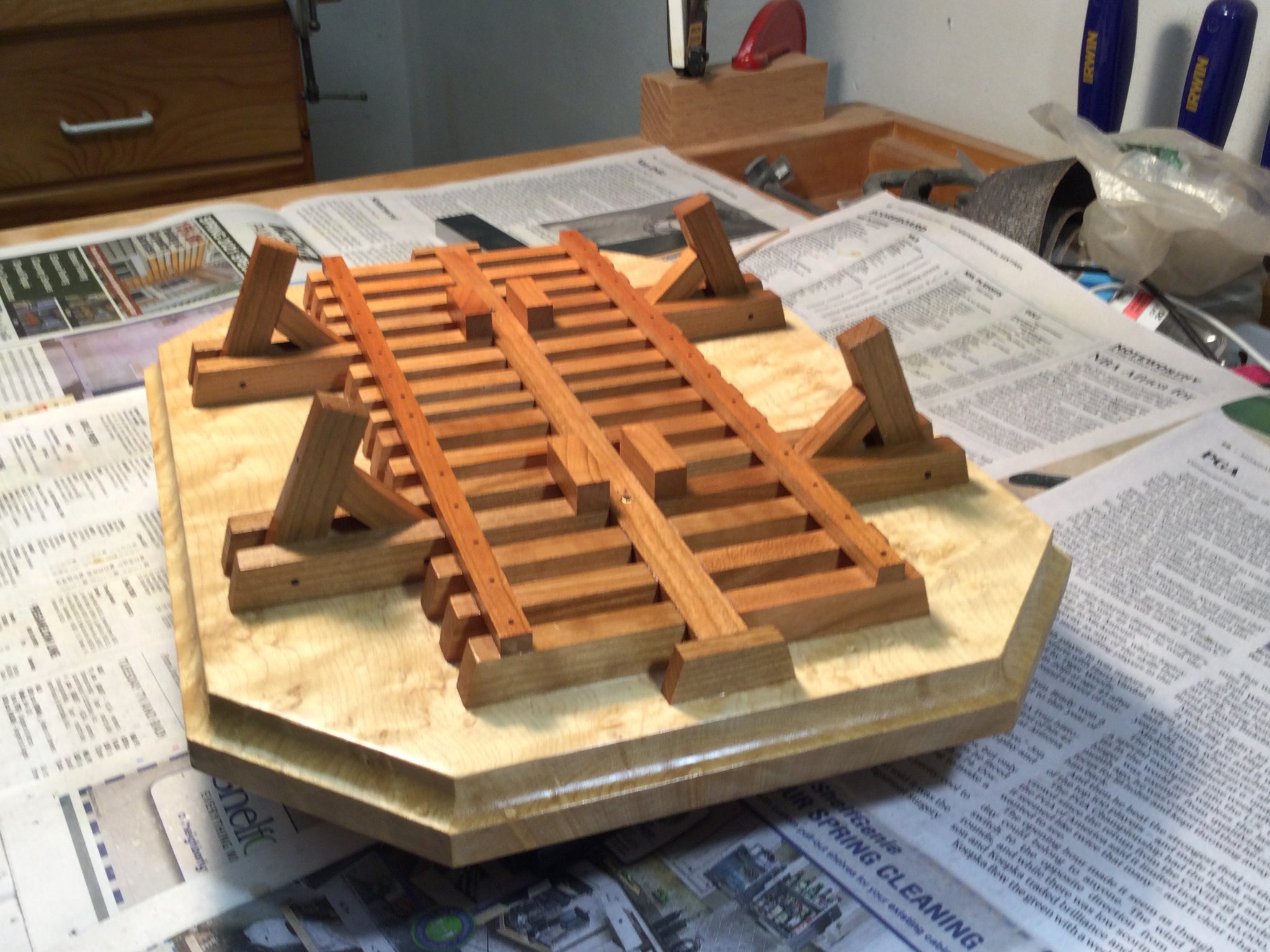
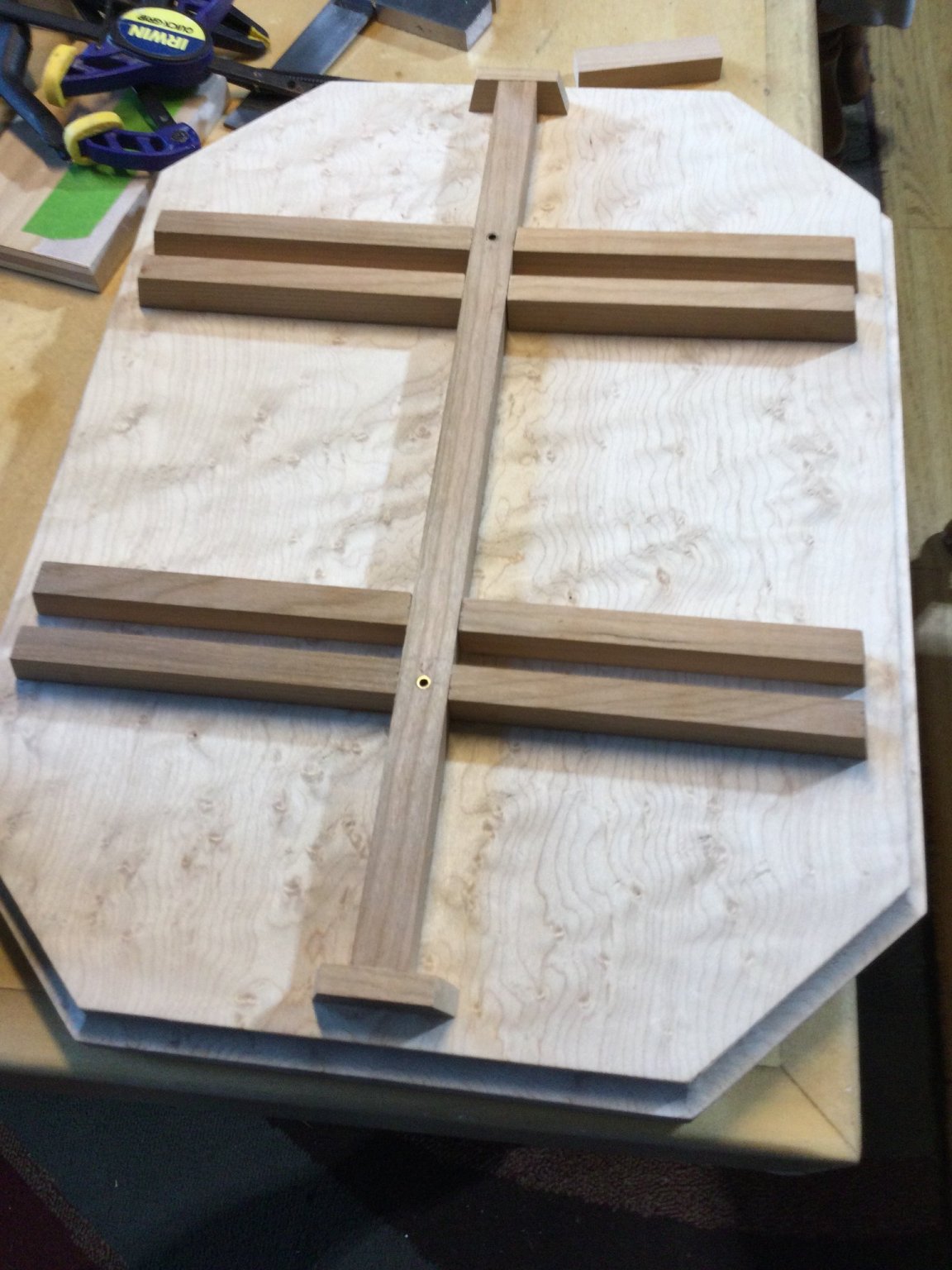
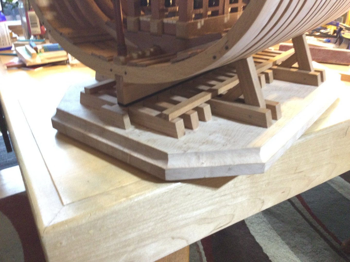
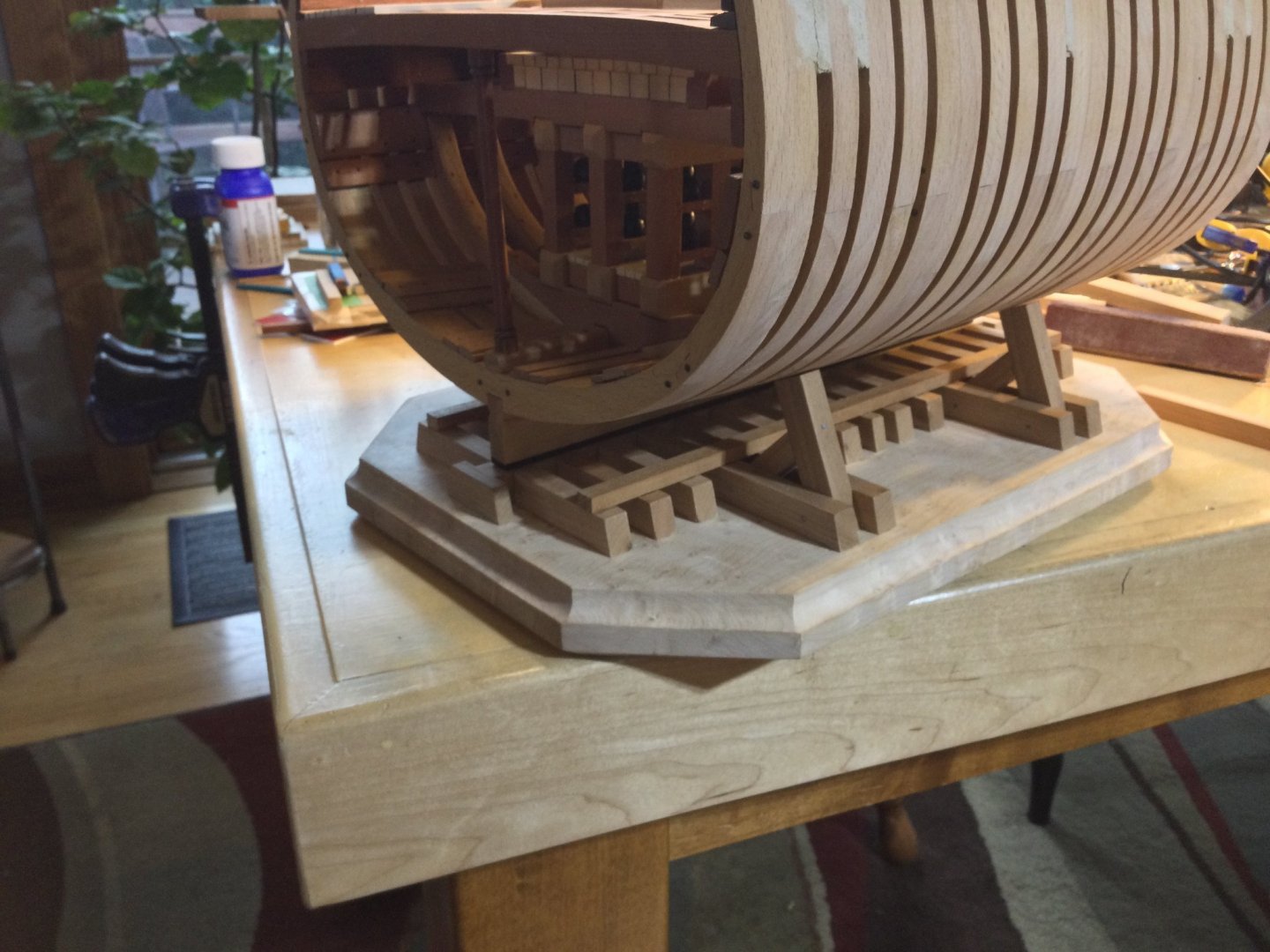
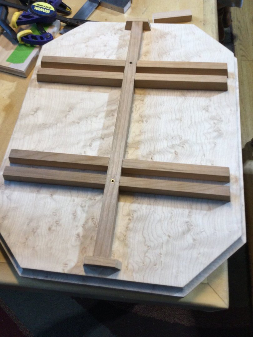
Thanks, guys! I put a couple of coats of poly on the display board. It really brings out the color of the cherry and the figure of the maple!


-
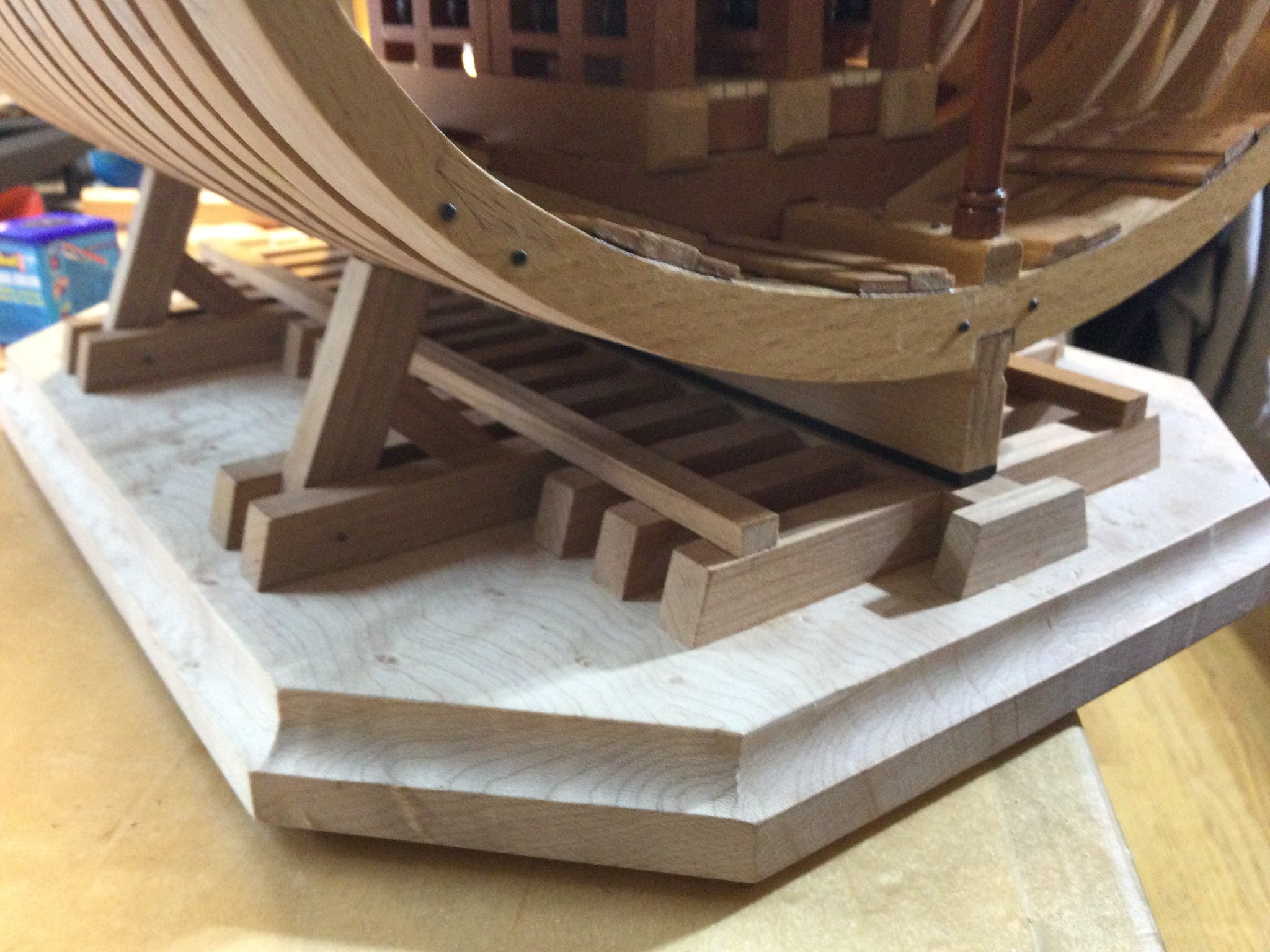
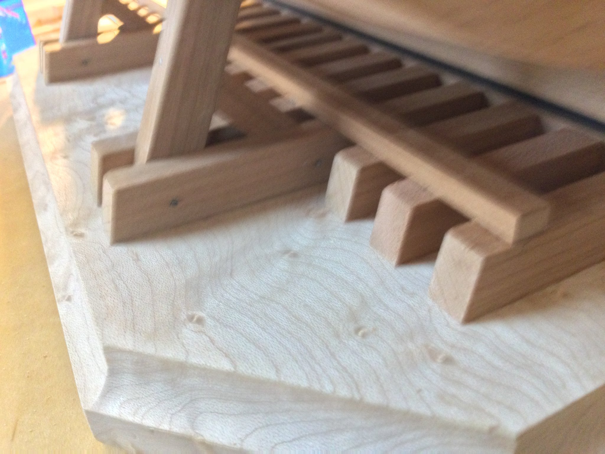
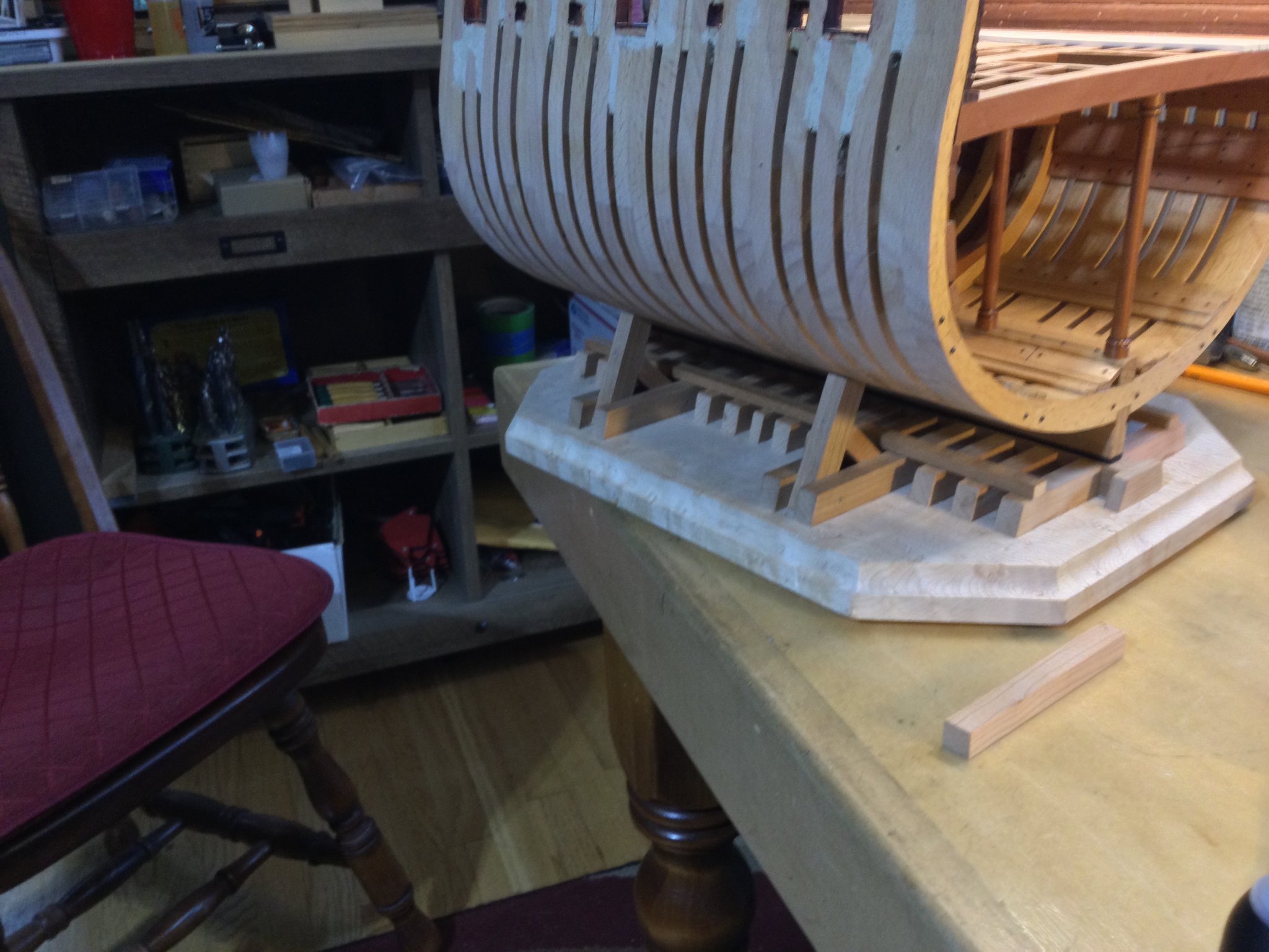
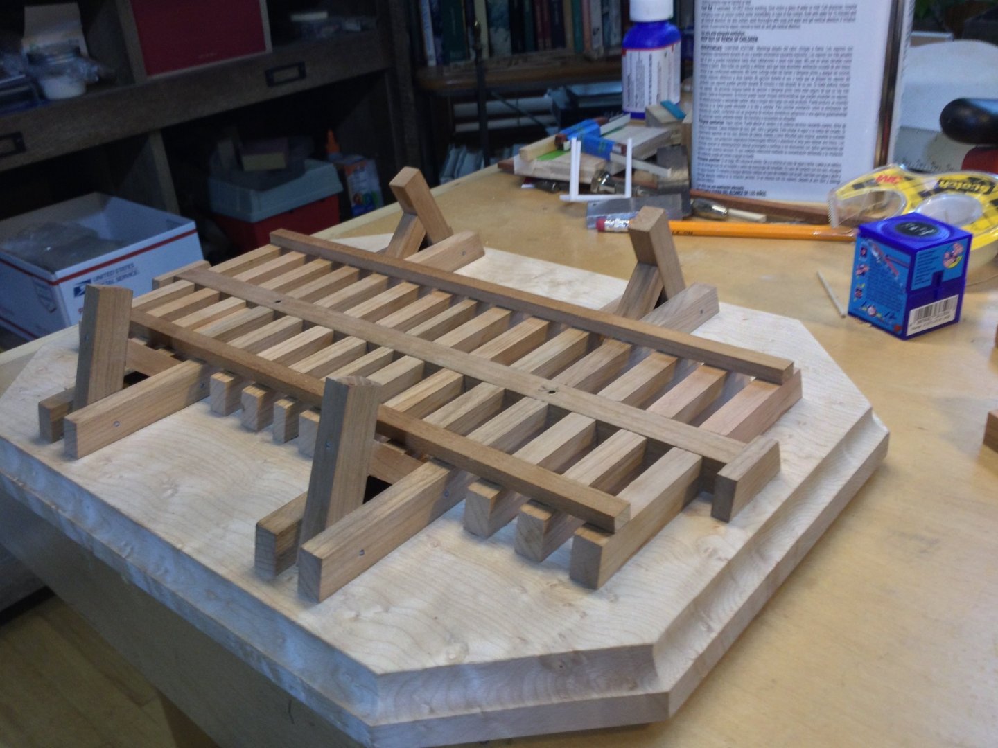
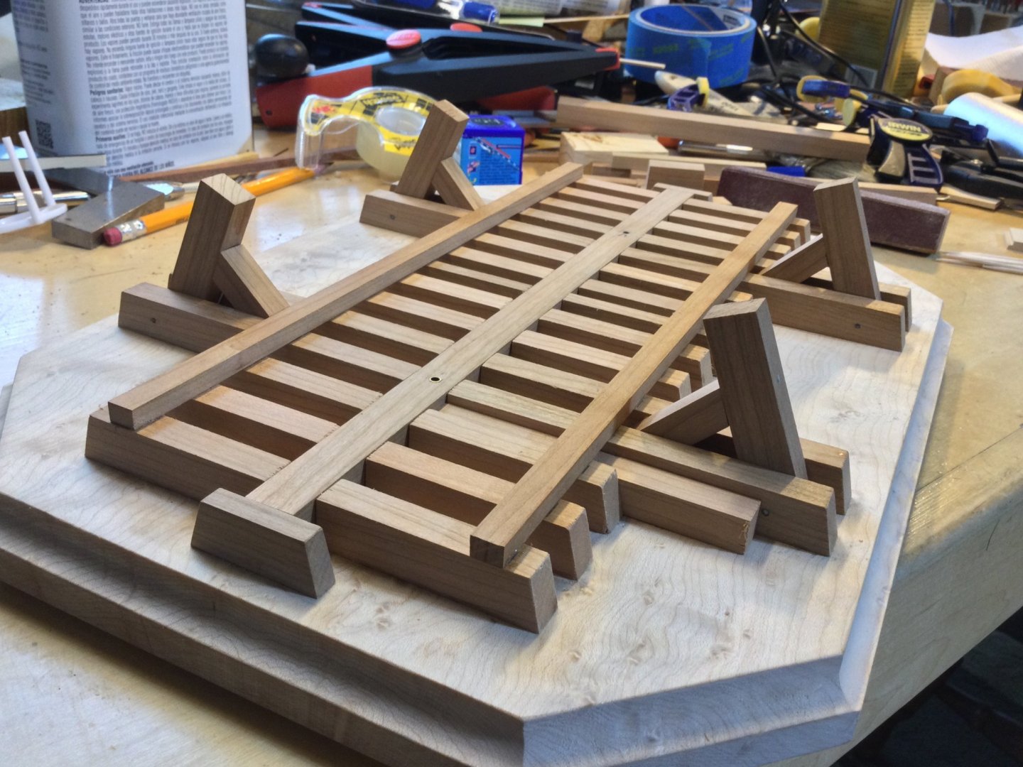
Thanks, Pat...and everyone for the "likes"! I added a little more to the base/launching ways to display the model. I still need some "curbs" on either side of the center timber to keep the keel centered where it should be. Once the finish is on, the contrast between the maple, beech, cherry and swiss pear will be more dynamic.


- 143 replies
-
- 13
-
-

-
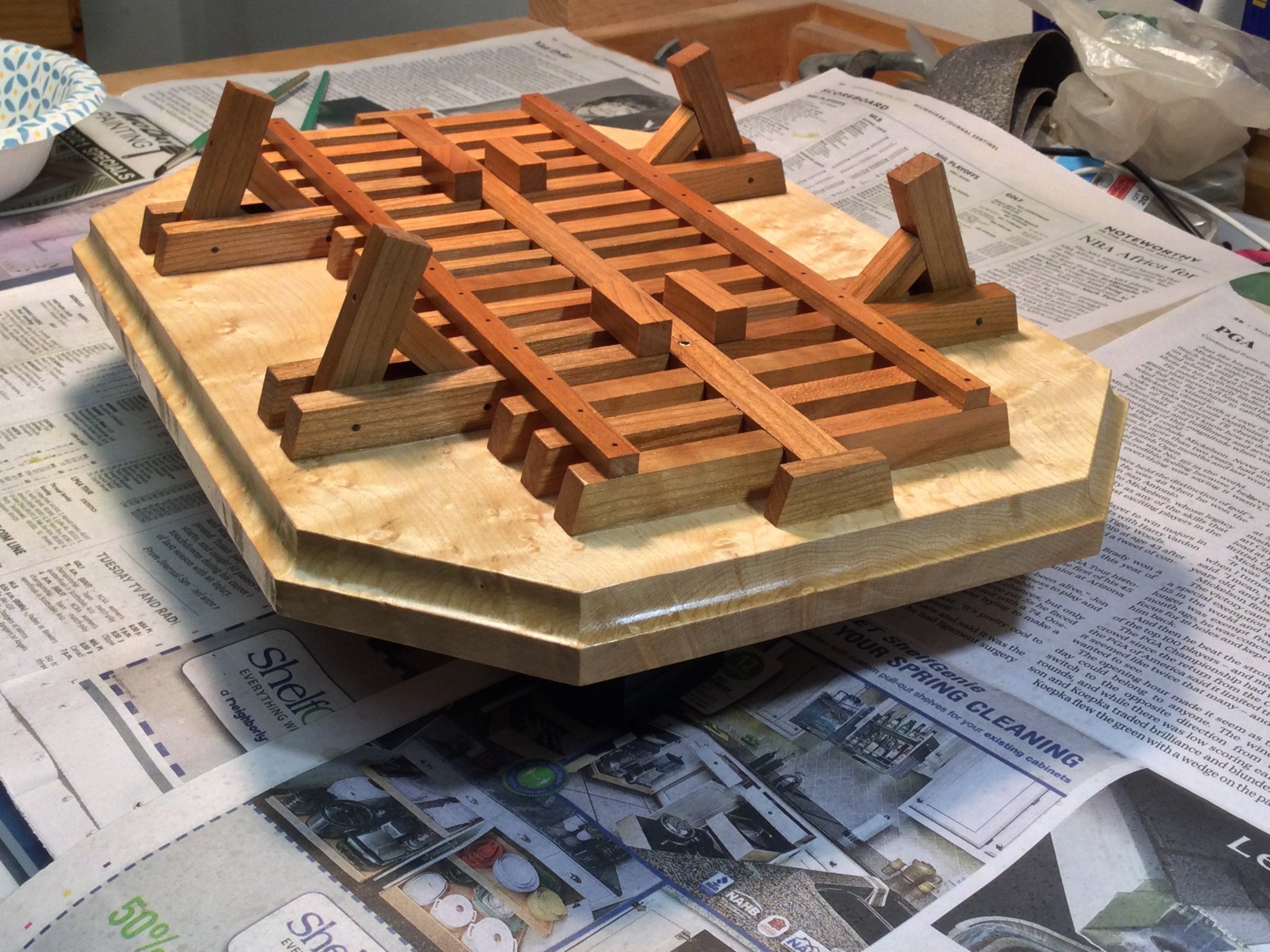
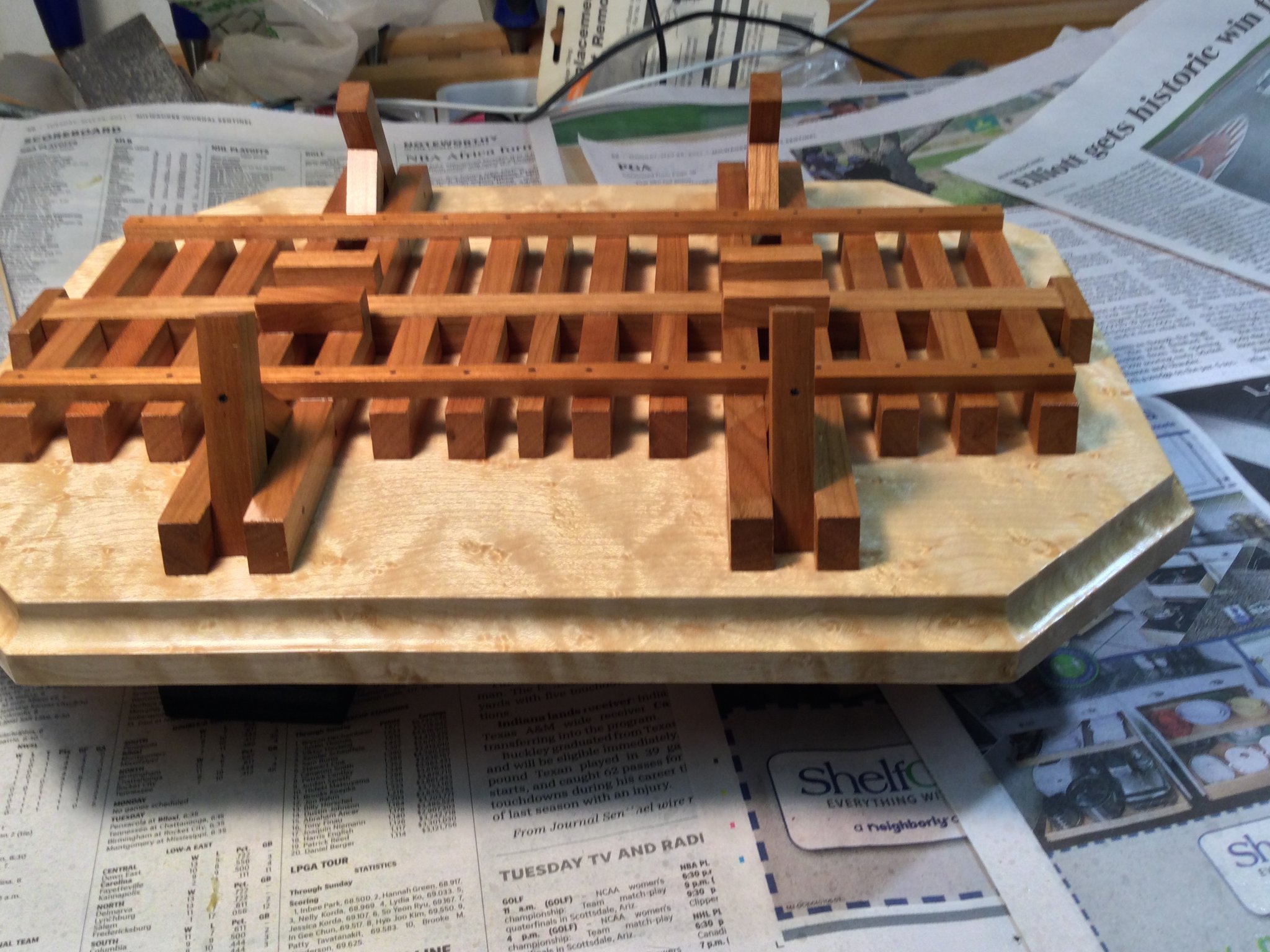
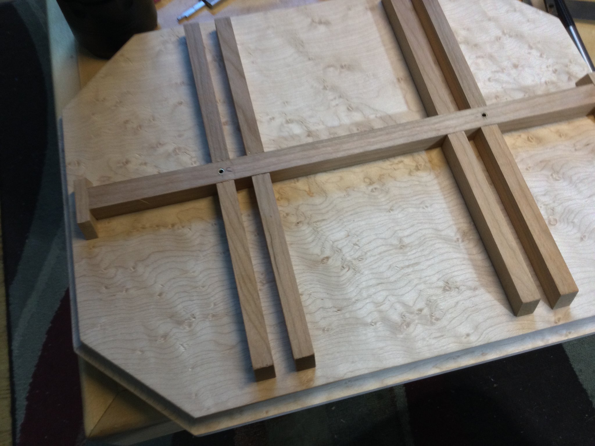
I'm getting ready to plank the outboard bulwarks. The jig will get in the way of the wales, so it's time to build a display stand. I have some curly bird's eye maple that I'm using for the base. The section will be cradled in scaffolding/bracing much as I did for my Blandford project. The wood is cherry.

-
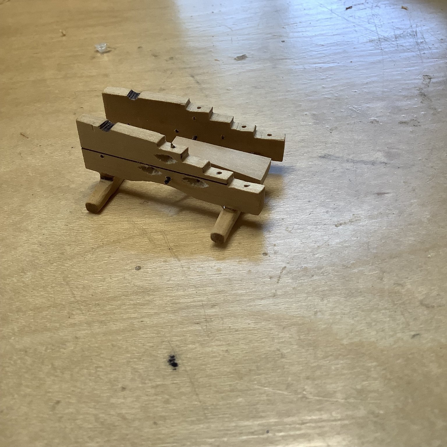
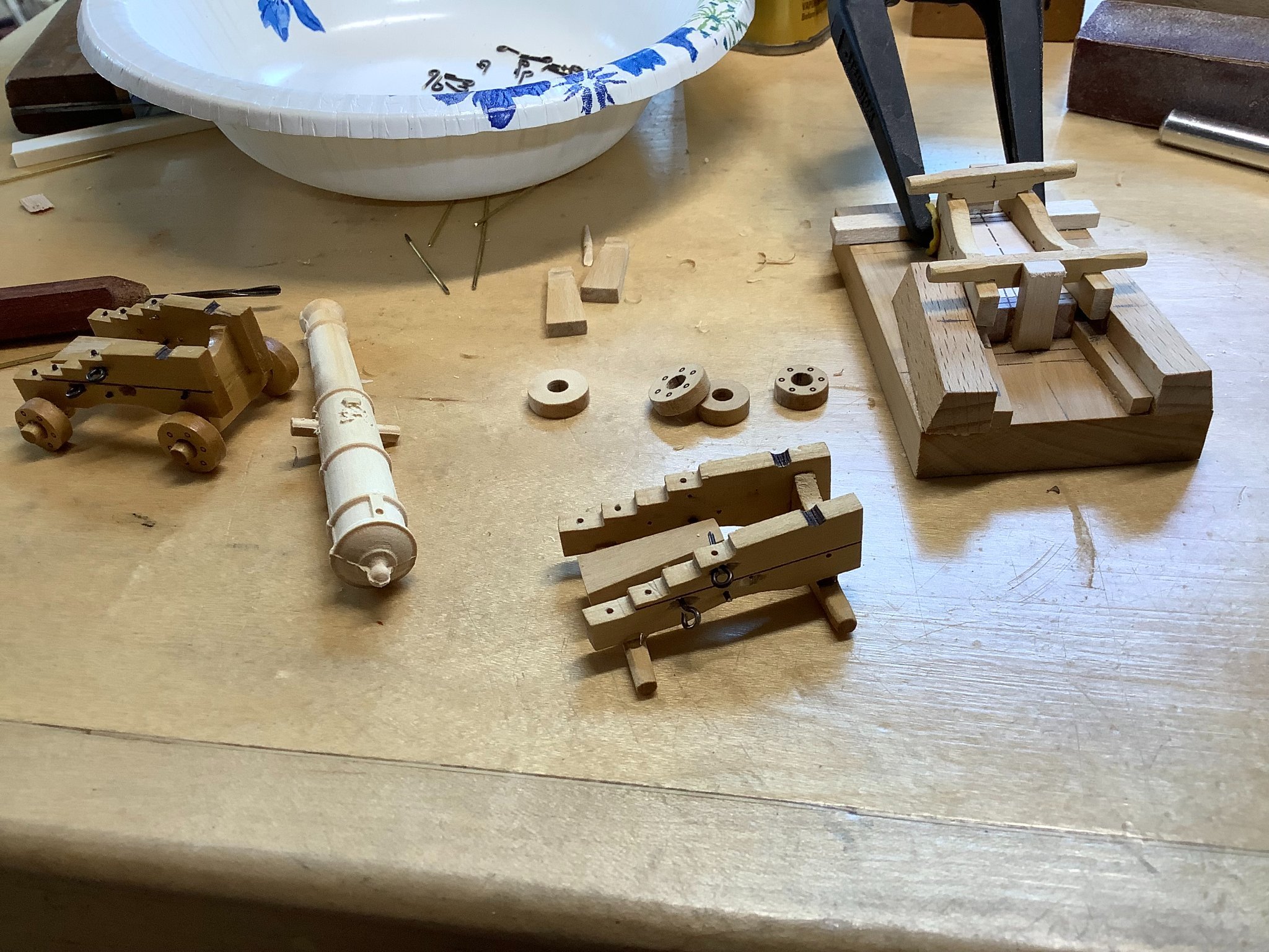
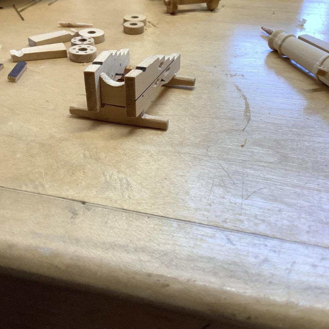
I've been busy! I just finished painting the inside of our house, including our family room, kitchen, foyer, 2 bathrooms and two bedrooms. I also removed carpeting and underlayment in two bedrooms to prep for installing hardwood floors...which is my next project! I have sneaked in a little modeling time, though. Here is some preliminary work on the cannons. I first built an assembly jig so everything goes together nicely and the same. The metal work will come next and then the trucks. You can see some shallow "gouges" in the carriage brackets where the eyebolts fit. This is so the eyebolts can be "buried" in the brackets as they were in real life, to prevent them from turning.


- 143 replies
-
- 12
-
-
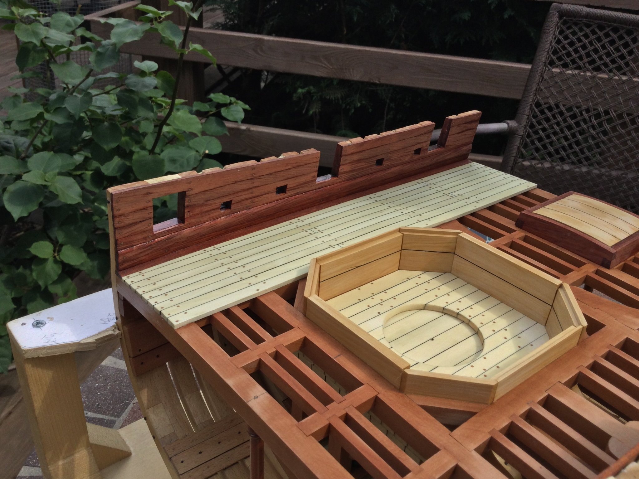
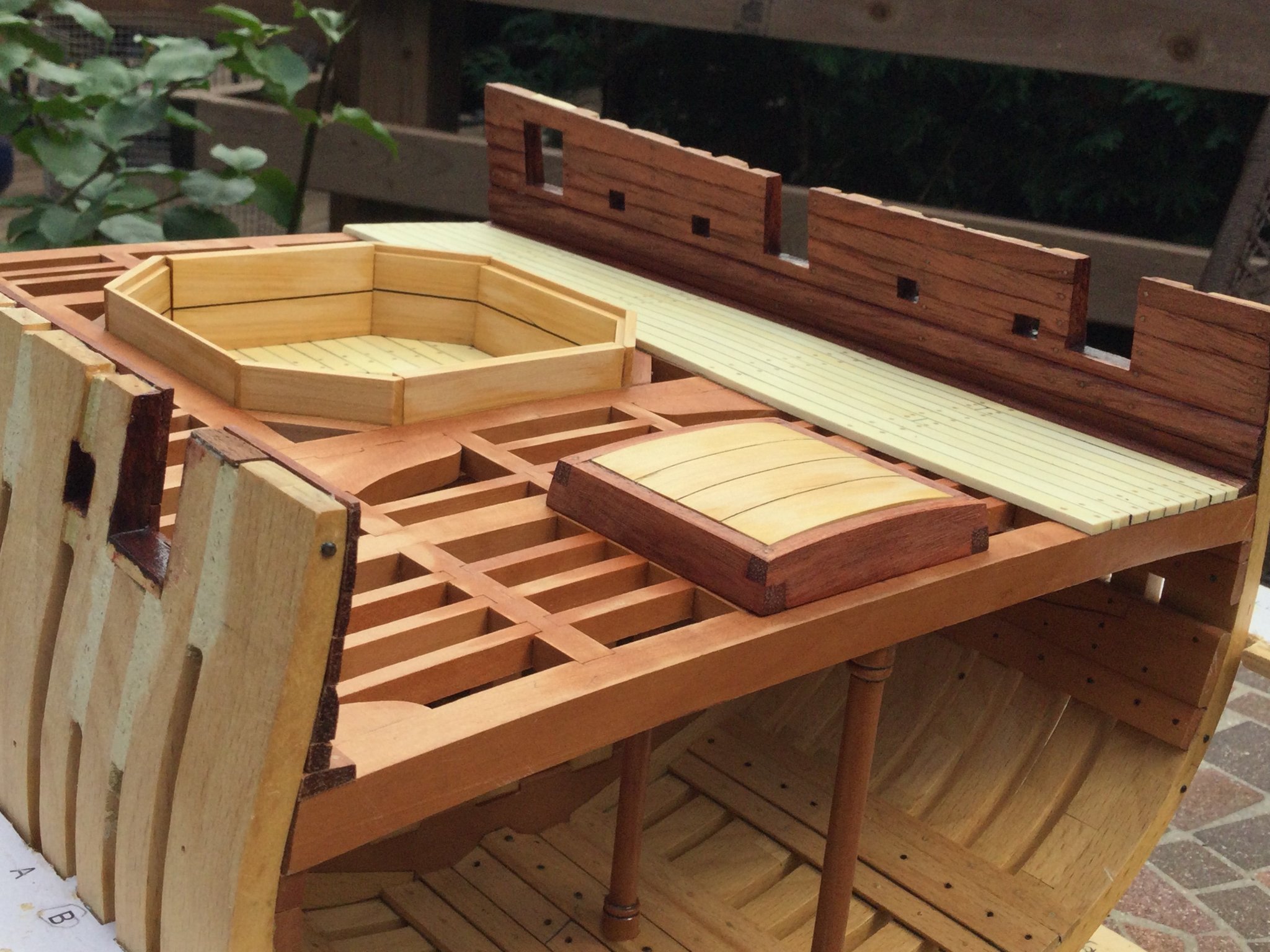
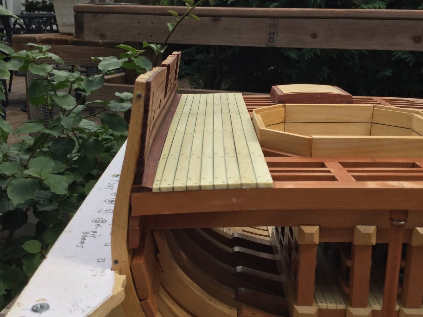
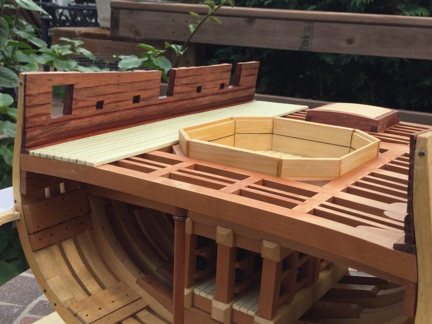
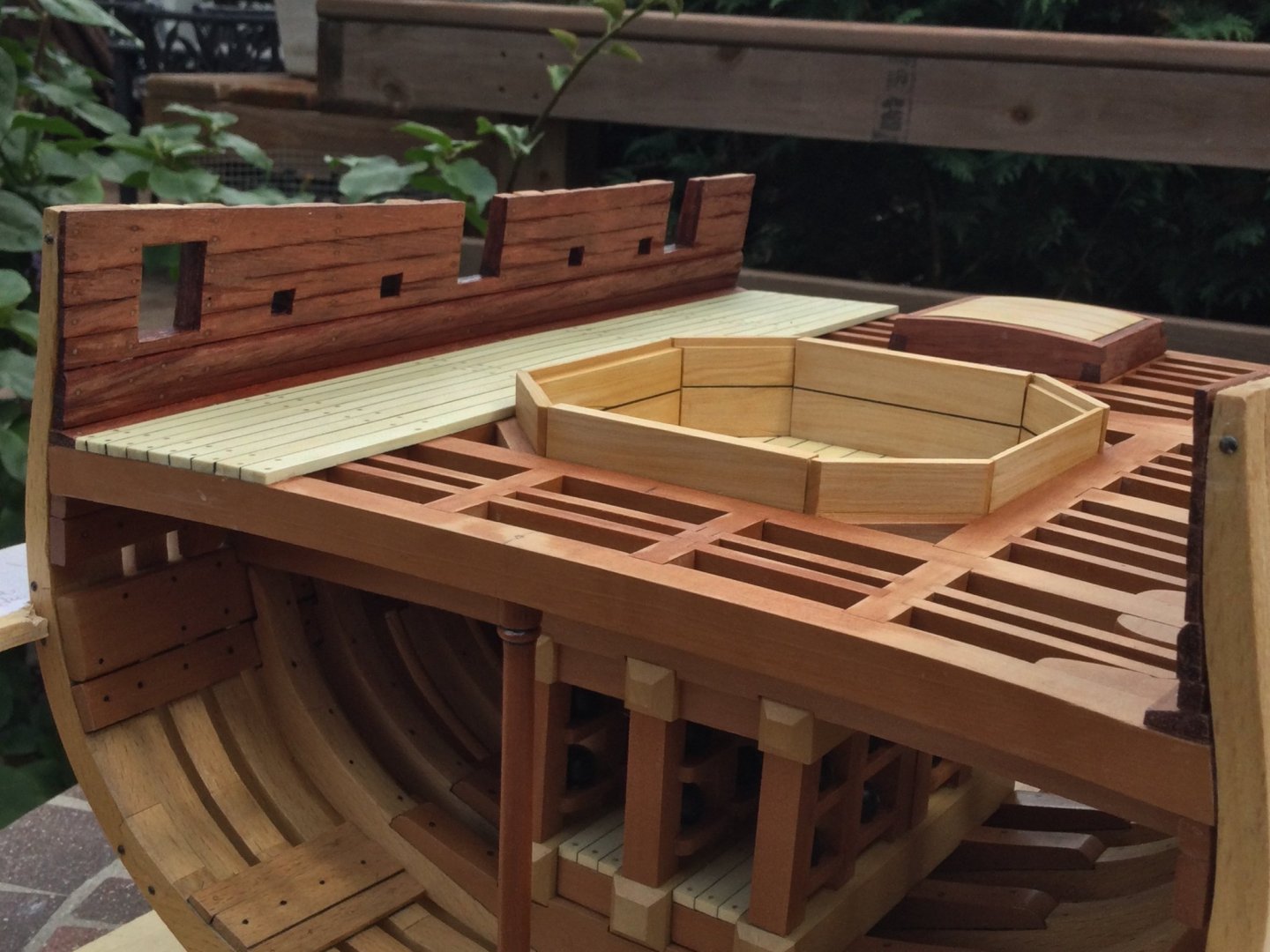
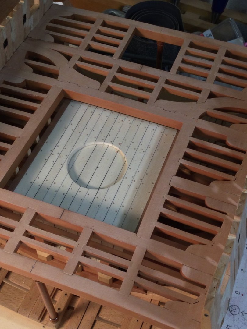
With lots to do around the house, I've not had much modeling time. I did finish the deck planking, though! I wanted as much deck framing as possible to show, but I still needed to accommodate three long gums. I started the holly planking at the outboard mortar pit bulkhead and worked my way to the waterway. The margin p[lank was custom fit. It turned out to be as wide as the others at it's forward end, with a bit of a taper aft. It turned out pretty well.


- 143 replies
-
- 14
-
-
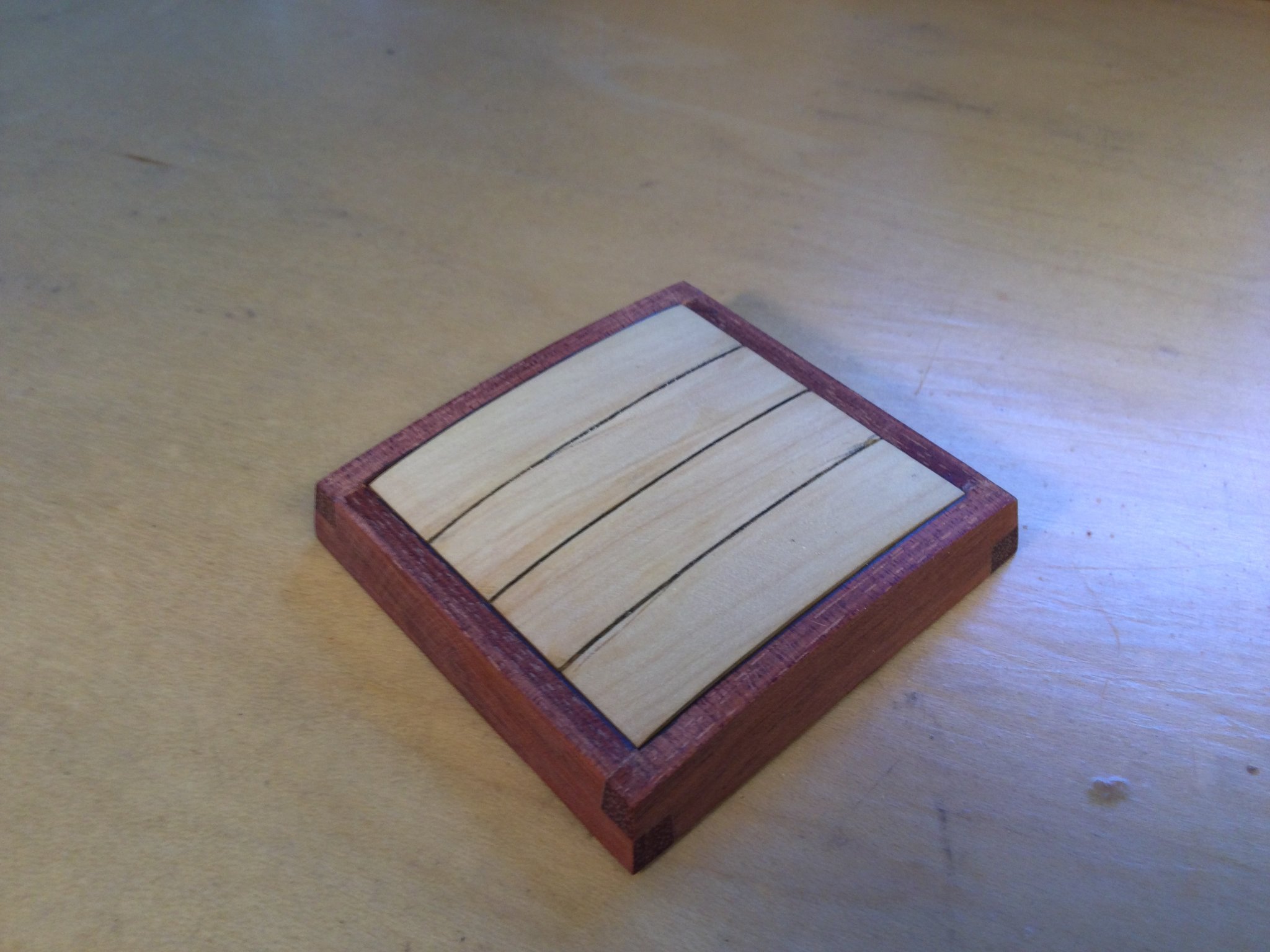
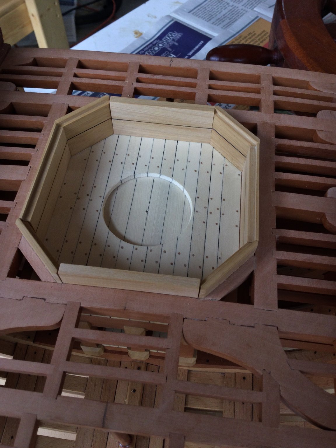
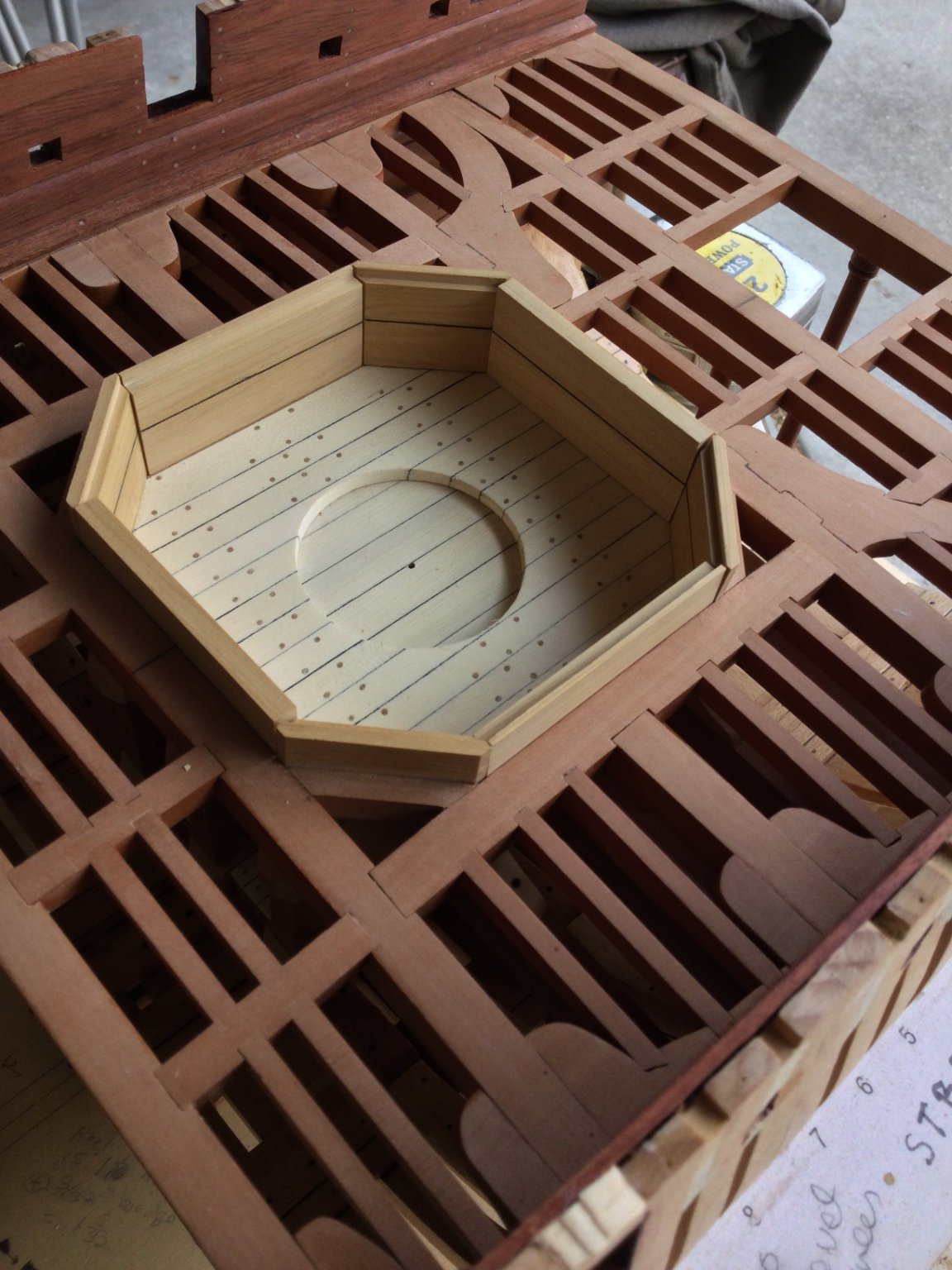
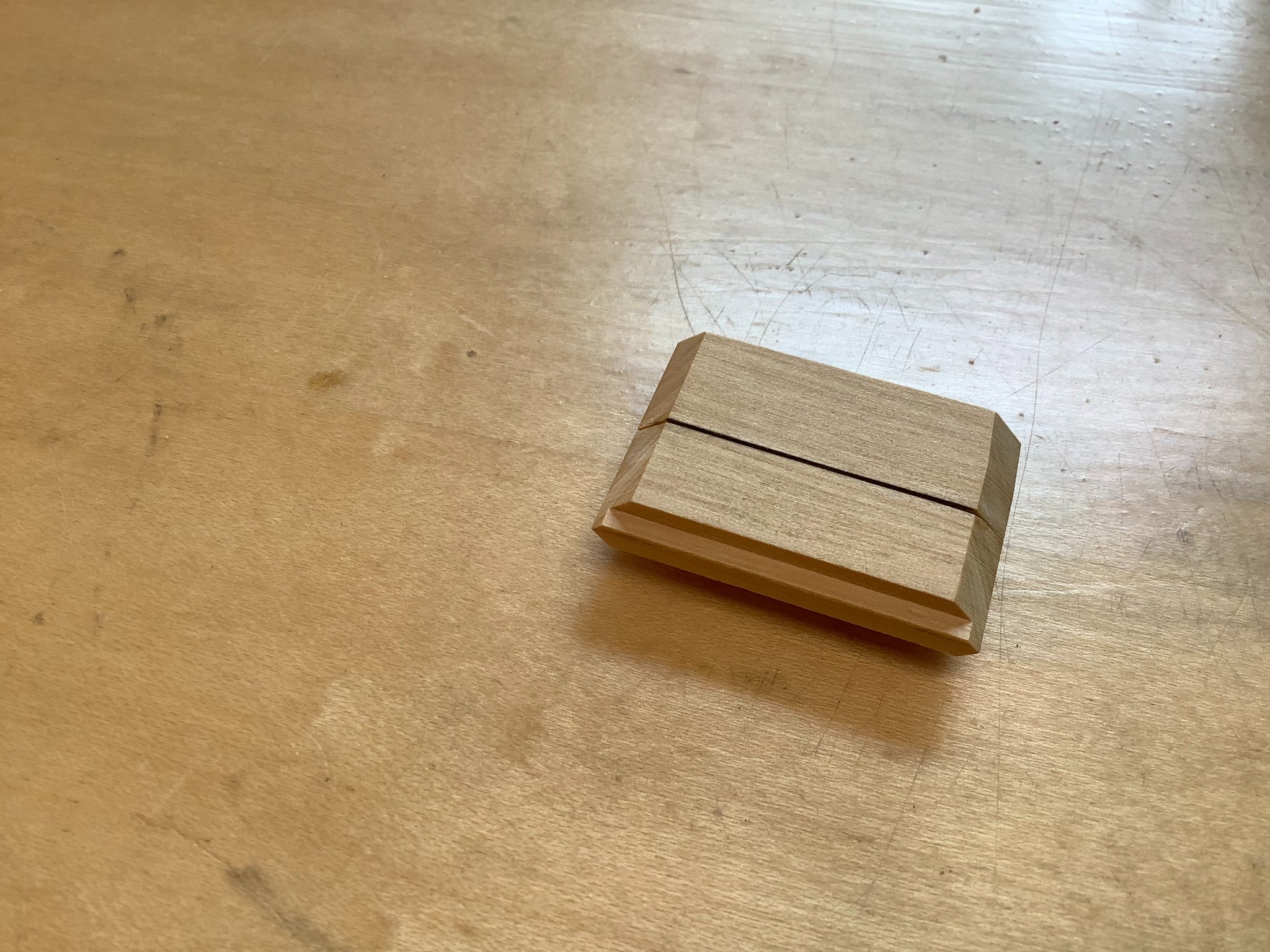
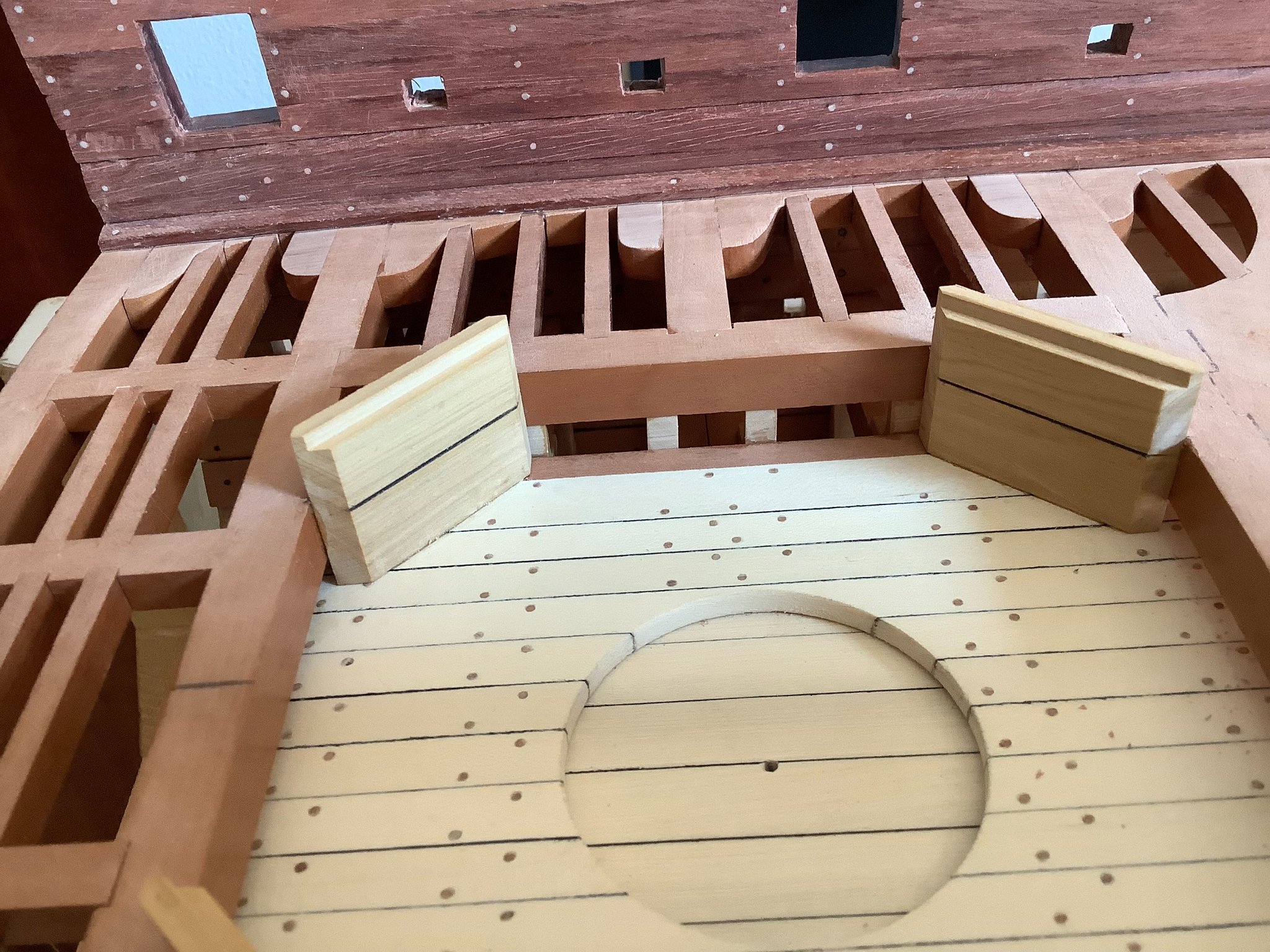
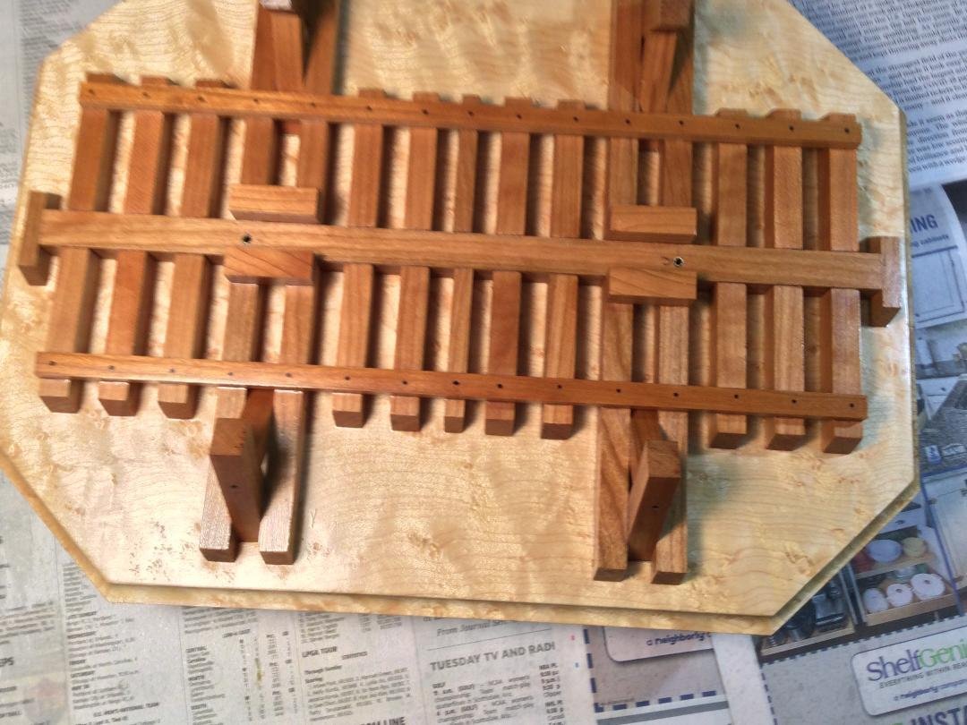
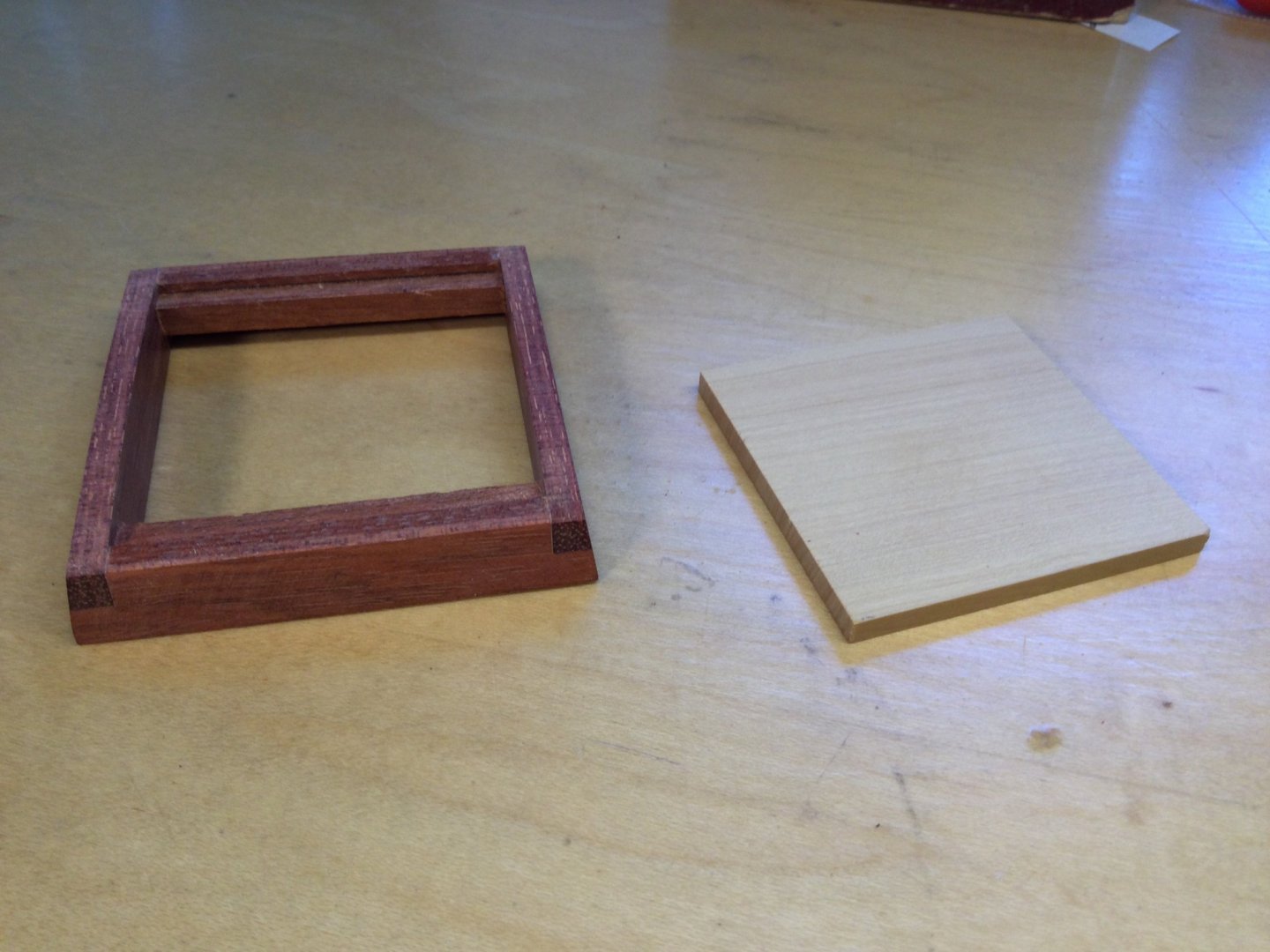
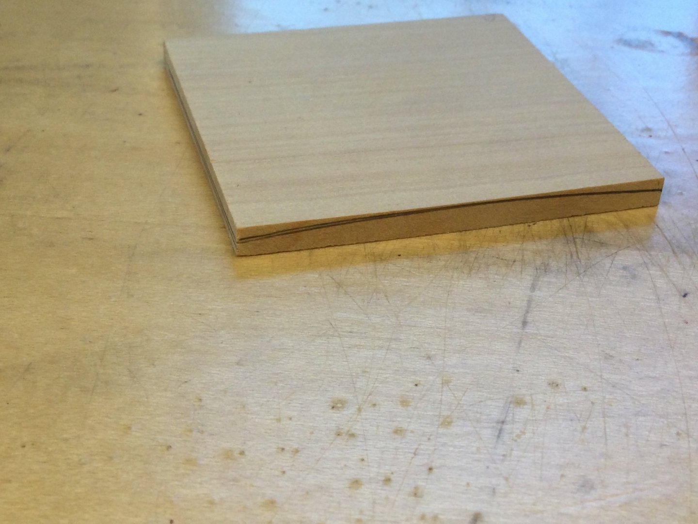
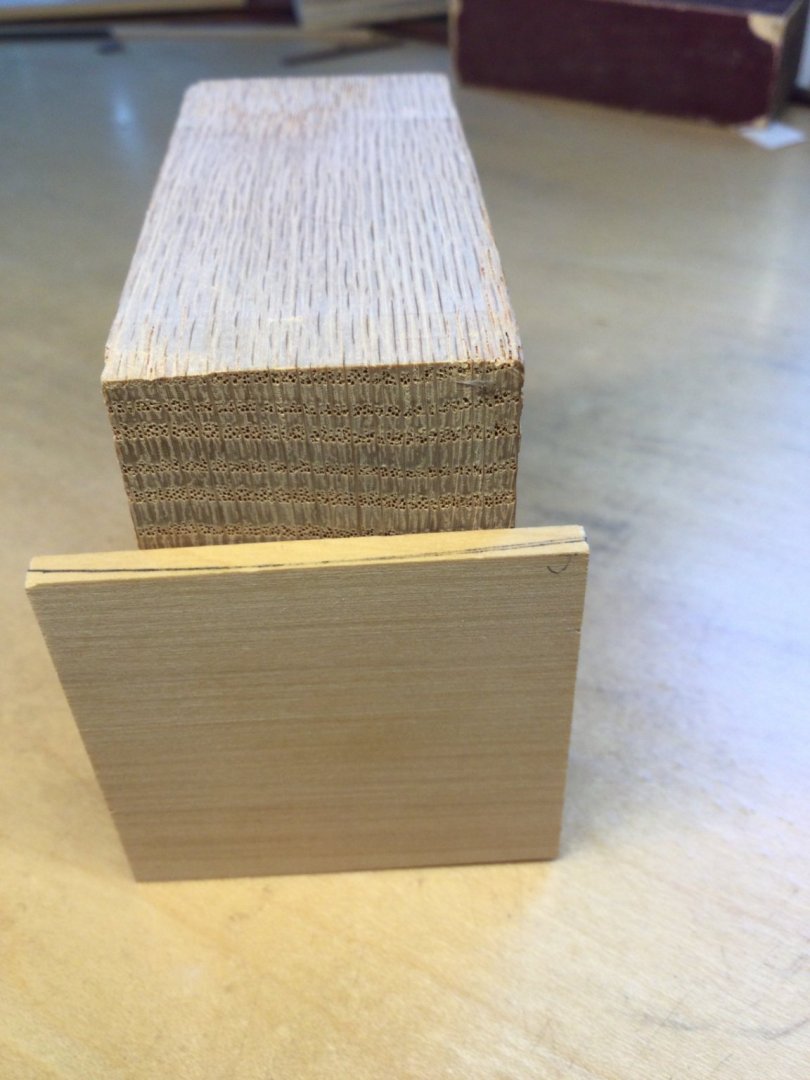
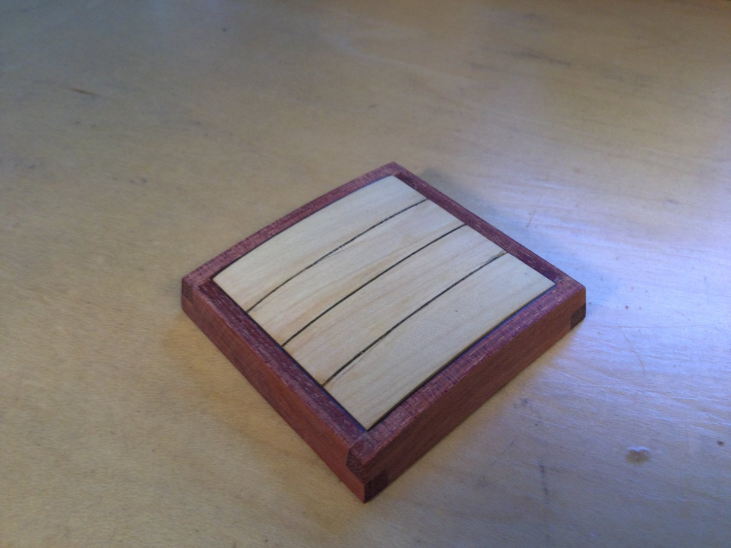
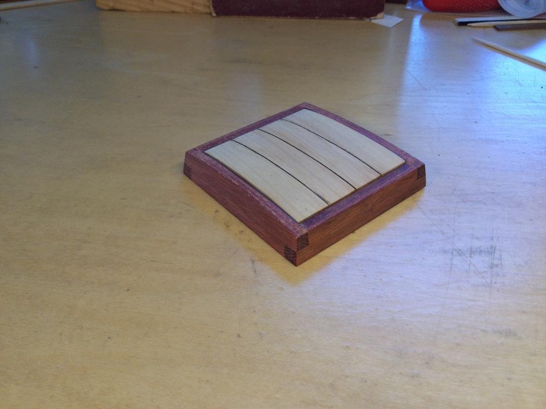
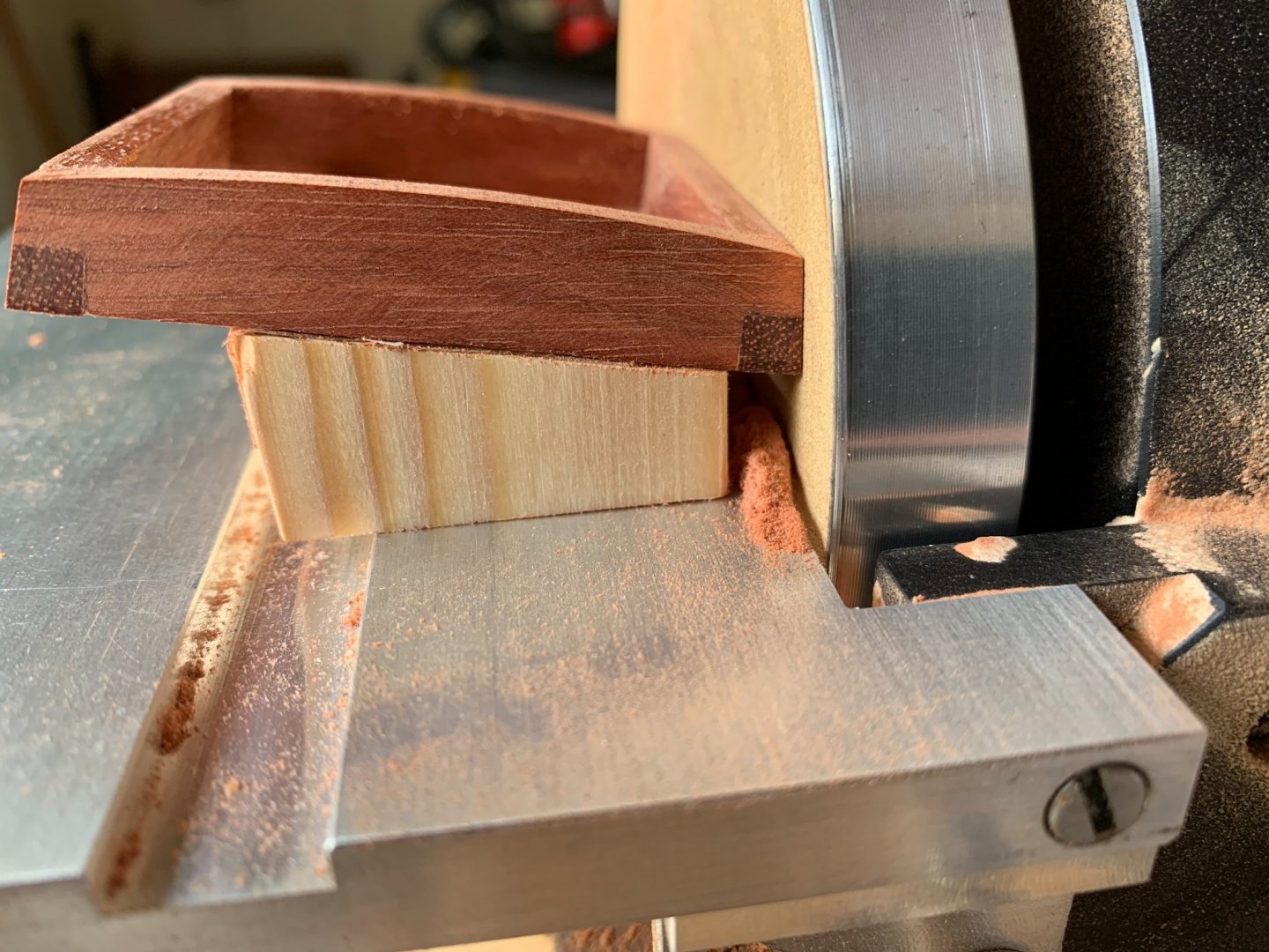
Thanks guys. for all the "likes"! I needed to figure out a way to make the hatch cover boards. I planned on using boxwood for the color contrast. The boards are about 5/64" thick with a very slight curve to them that matches the curved coamings. But bending the curve and getting the precise length right cutting strip stock was going to fail! Too hard to get consistency in the four boards. Here's what I did: I cut up a boxwood blank the fit into the recess where the boards sit. It was thick enough so it stood just proud of the highest point on the curved coamings. Then I traced the coaming top lines onto the 4 edges of the blank. I used double sided carpet tape to tape the blank to a block of wood, keeping it perpendicular to the table of my disc sander, and parallel to the disk's face. Using my variable speed disk sander on LOW speed, I sanded the curve into the blank! Once I was satisfied with the curve, I took the blank and simulated the four boards by scoring them in and darkening the score lines with very thin pencil lead. It worked out well!


- 143 replies
-
- 17
-
-
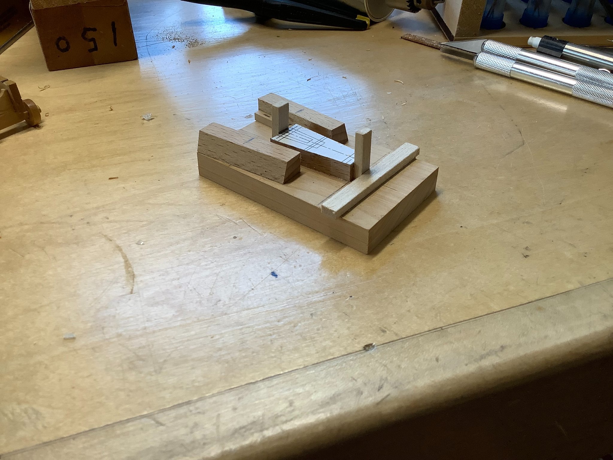
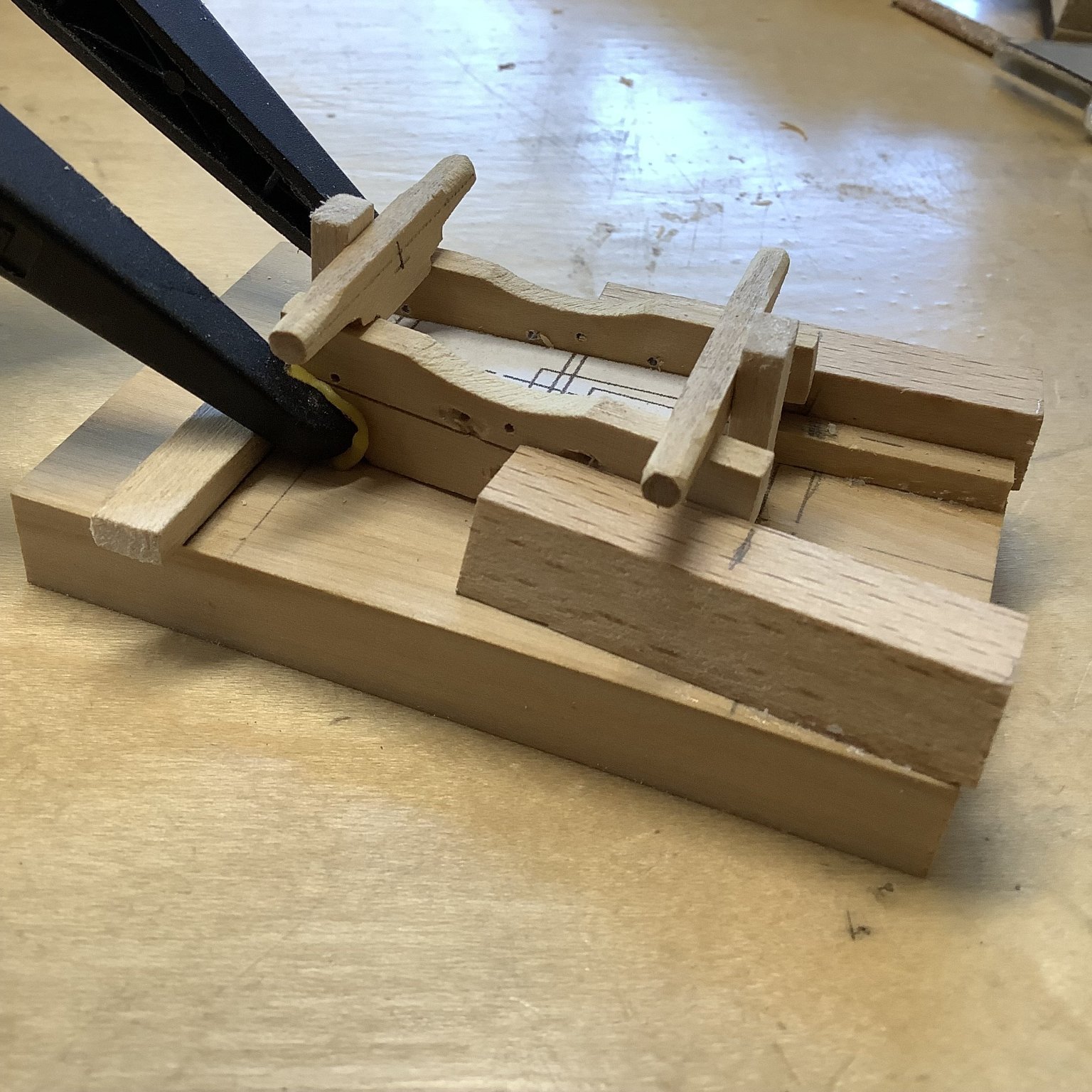
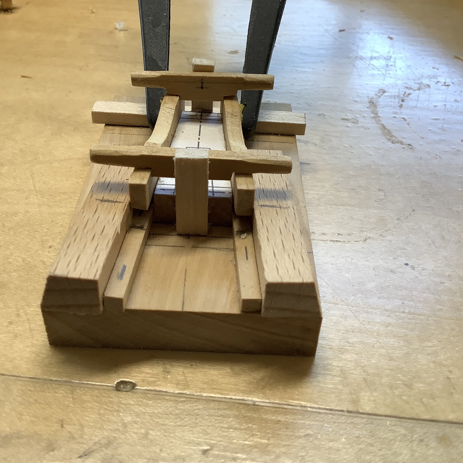
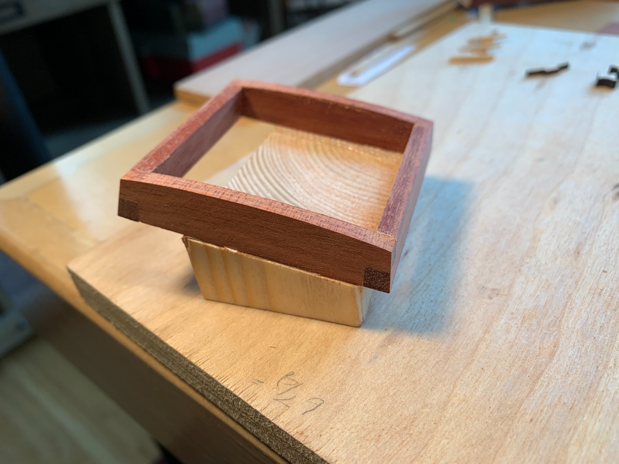
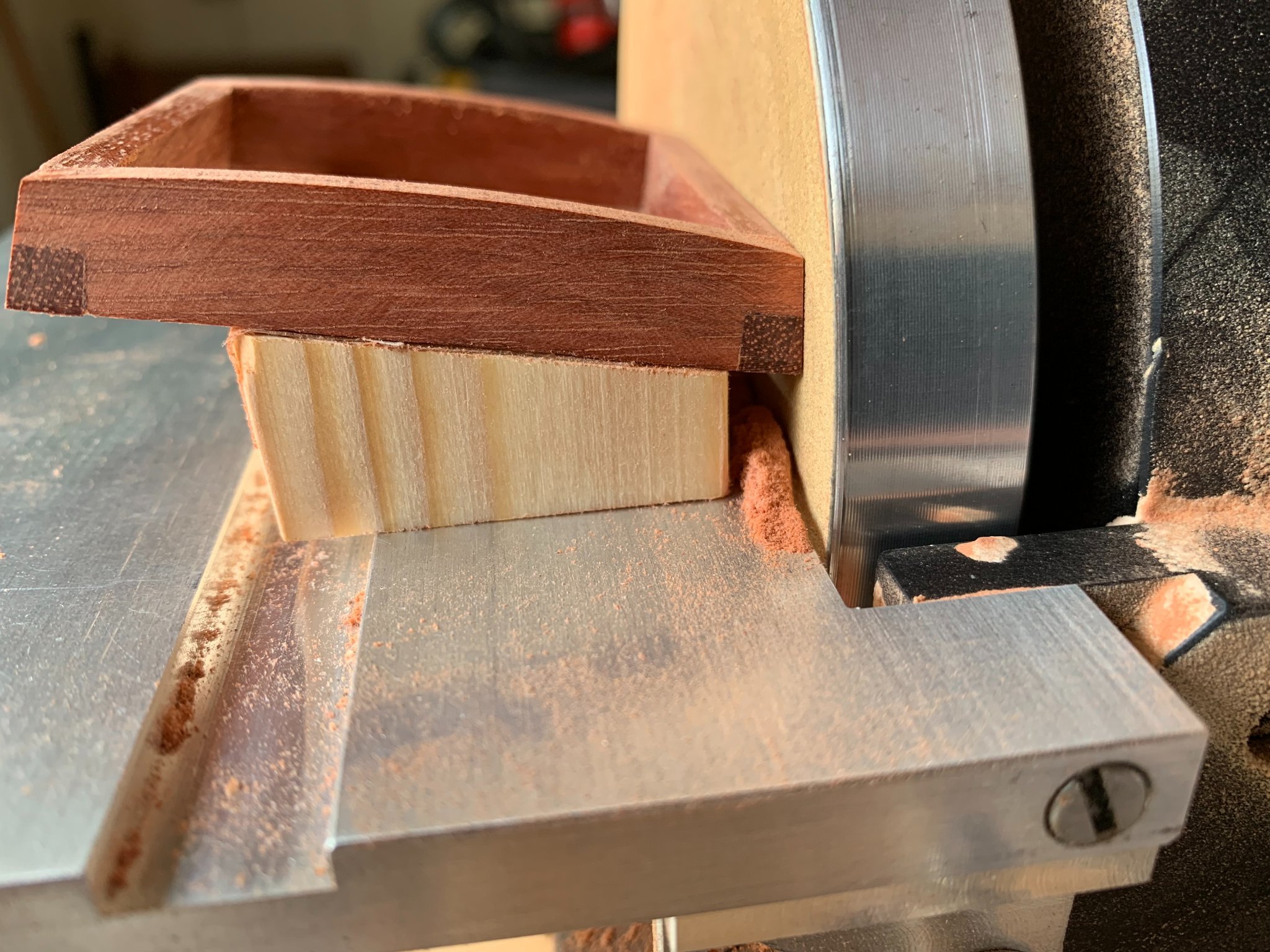
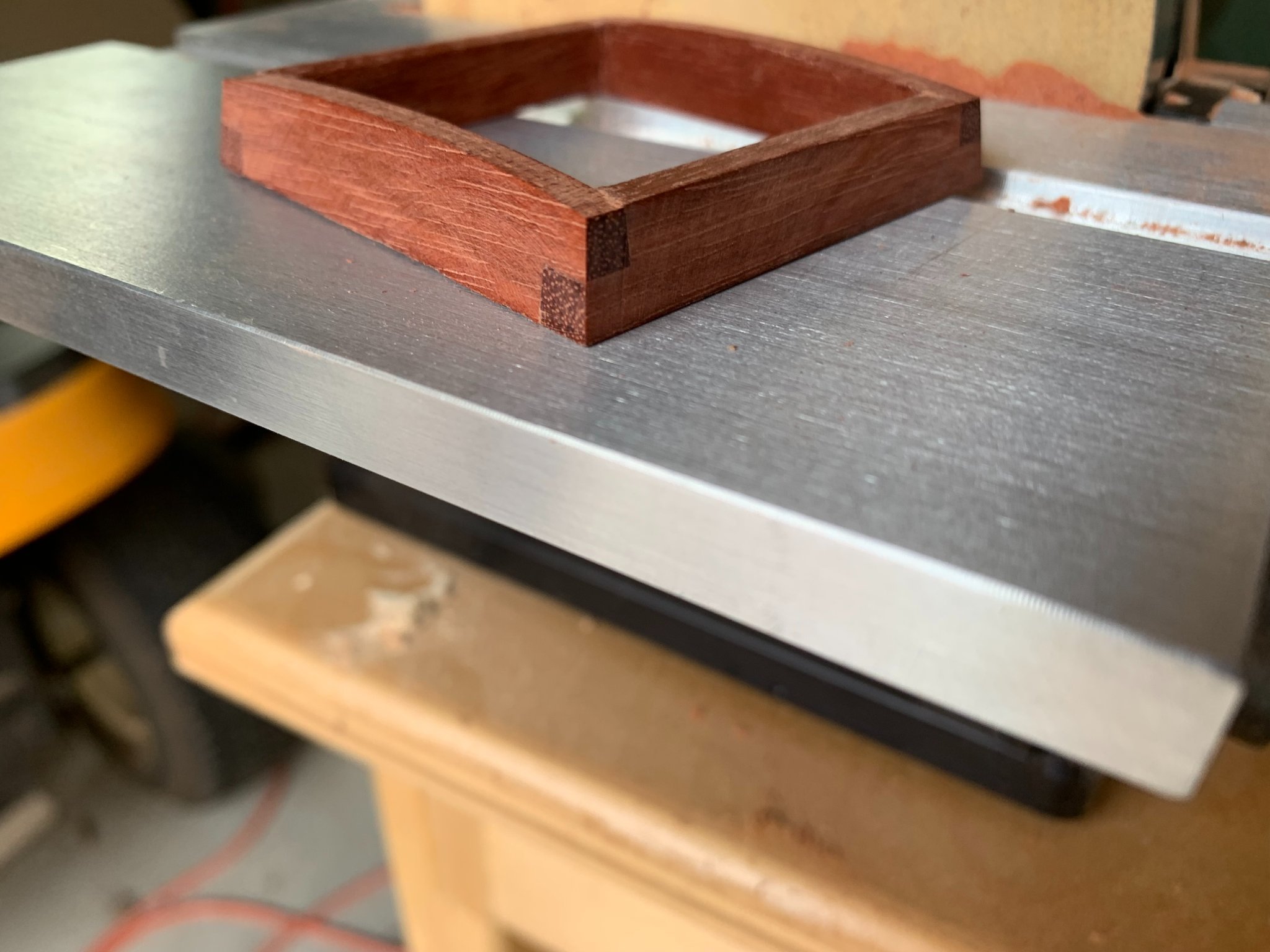
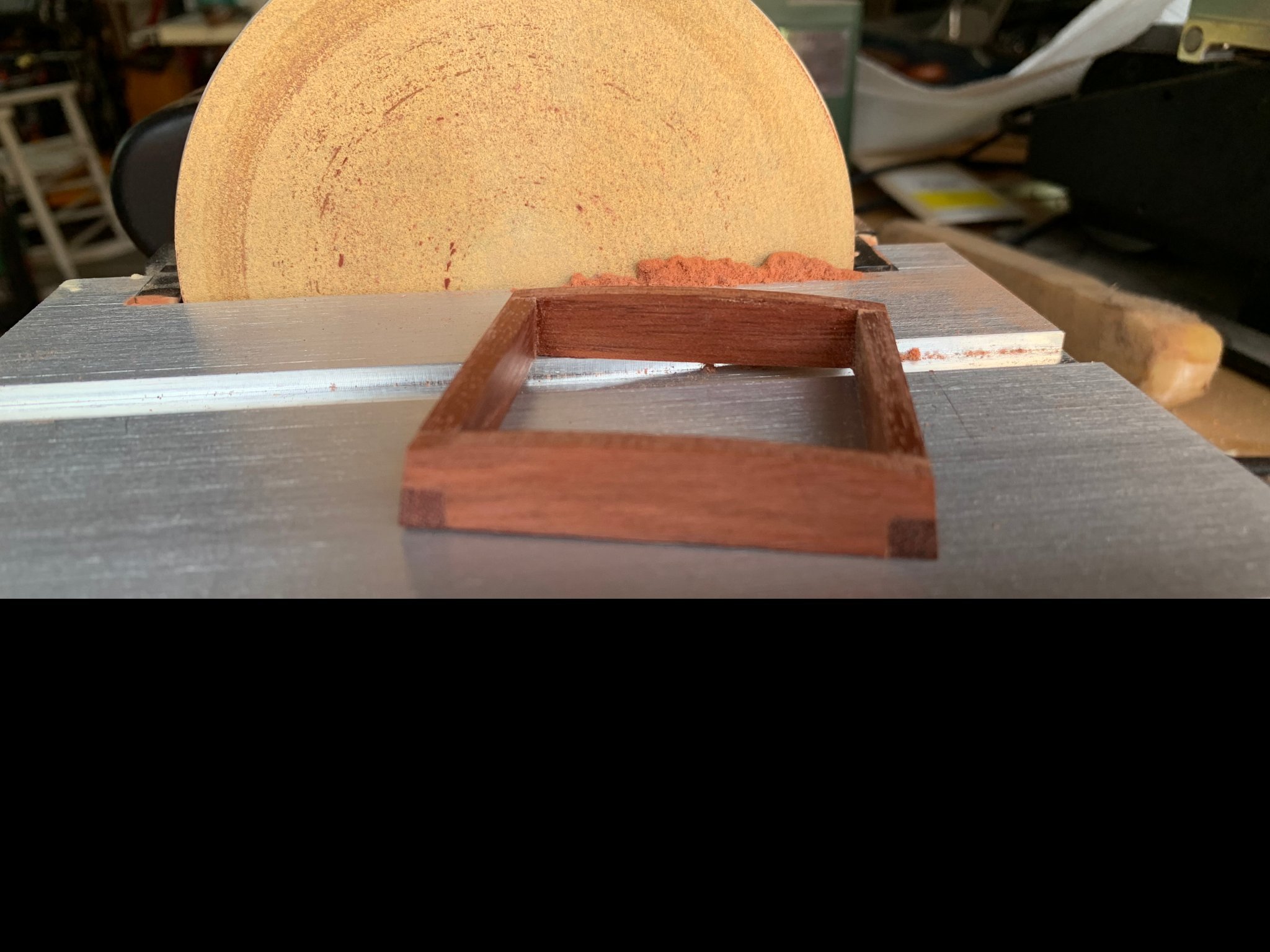
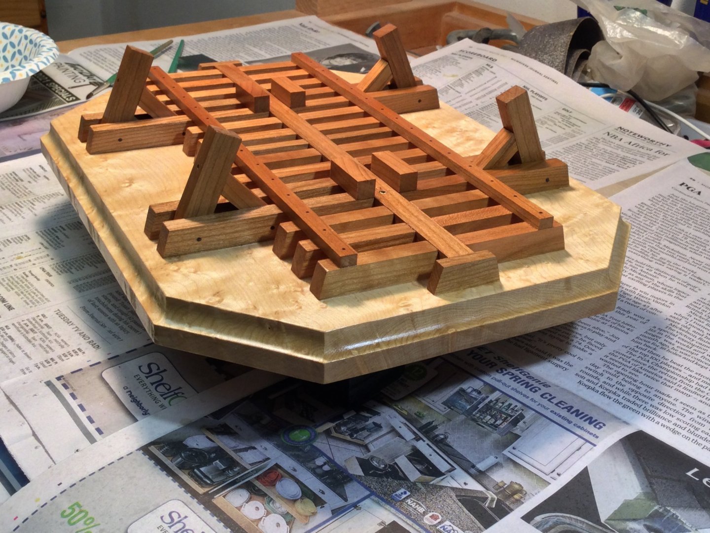
I started work on the hatch. The coamings are 7/32" thick bloodwood and jointed by half laps at the four corners. The coamings are also beveled inward by 10 degrees on all four sides. How to do the beveling easily and accurately? I decided on a jig! Basically the jig is a slice of wood, angled at 10 degrees from the horizontal. When the face of a coaming is sanded such that it is square up against the Byrnes sanders disk, you know the angle is a perfect 10 degrees. The hatch frame is attached to the jig with two sided carpet tape. Sanding the four sides took about 20 minutes.


- 143 replies
-
- 15
-
-
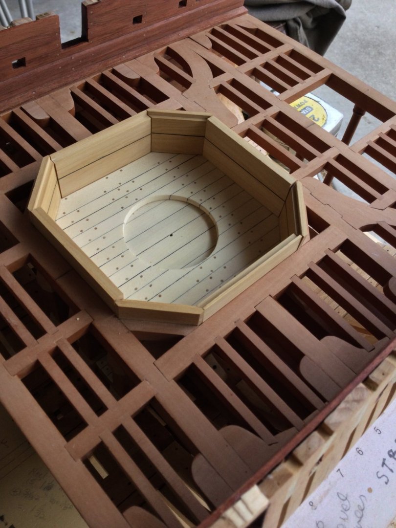
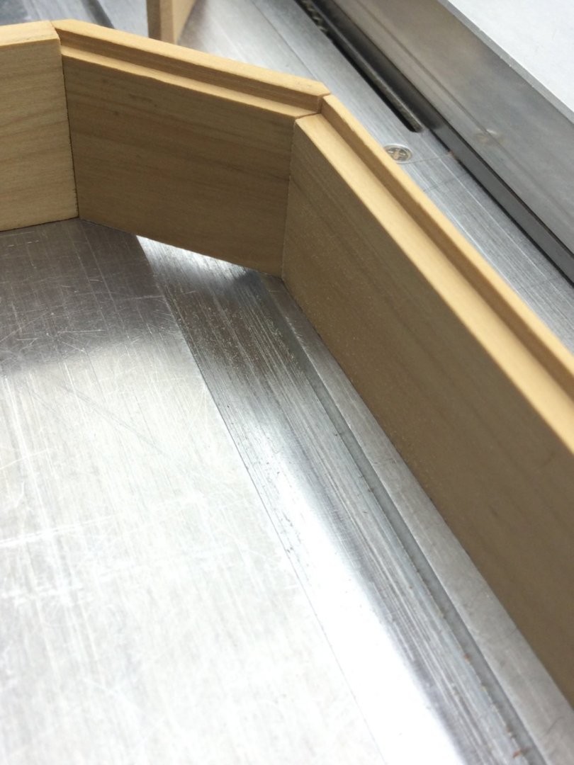
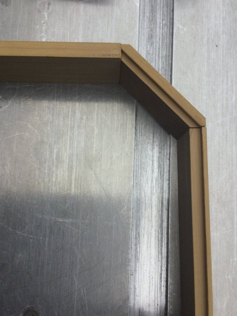
Thanks, guys! The complicated anatomy of the ends of the angled bulkheads actually makes fitting the outboard and transverse bulkheads easy. They are cut a little long at a 90 degree angle. I then "sneak up" on the final width with the Byrnes sander.

- 143 replies
-
- 16
-
-
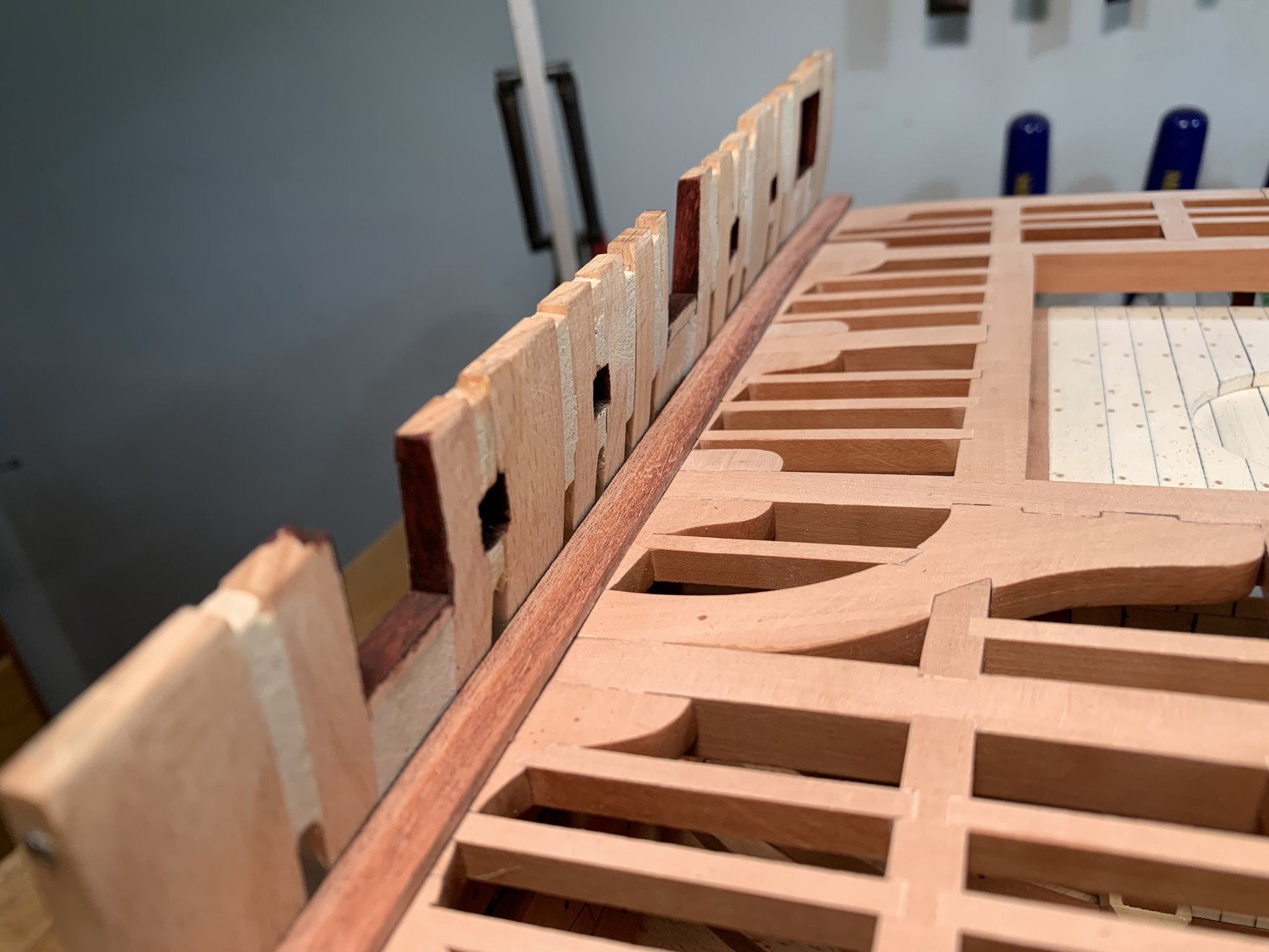
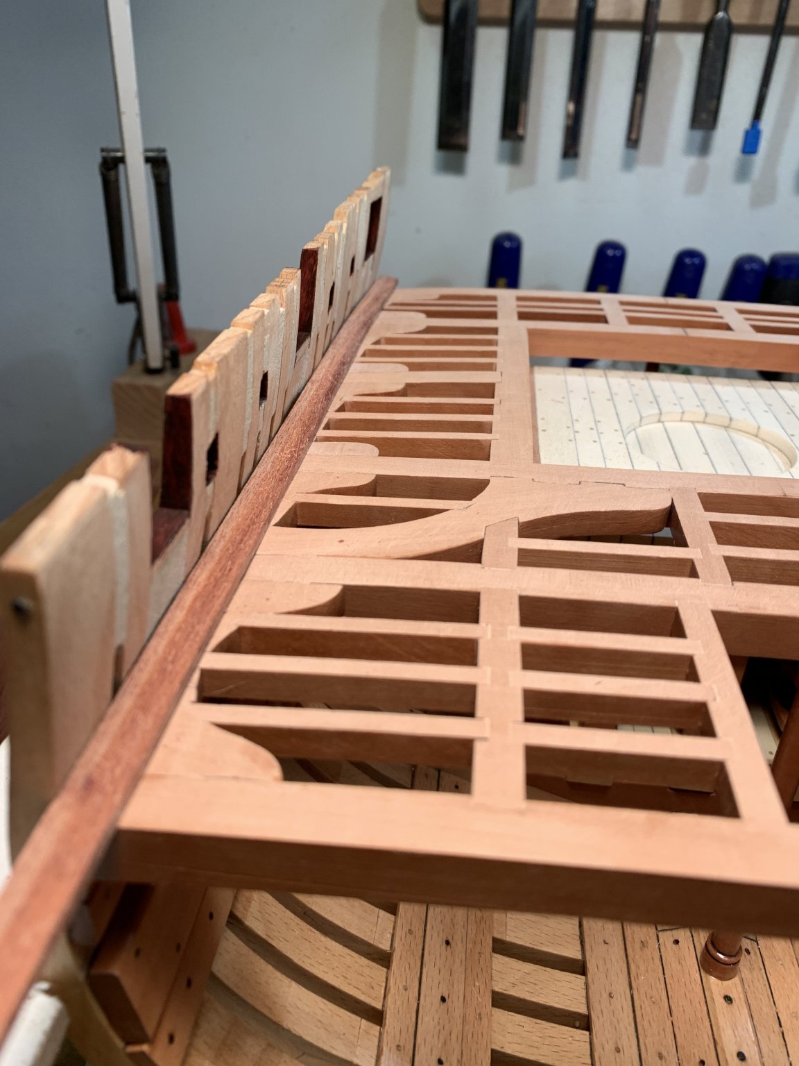
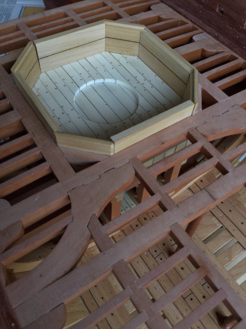
Thanks, guys! Pat: I'm eyeballing the cuts, but I have a plan view rubber cemented to the bottom of each blank to guide me! I prepared the diagonal bulkheads for installation. The backs of the 4 bulkheads are supported by diagonal carling which are inset into mortises in the deck beams and trimmer beams. I decided to make life simple and simply butt the diagonal carlings in place. I carefully cut them to size, then glued them to the back of the diagonal bulkheads. The bulkheads are built with two boards. I simulated this by scoring a line and marking it with a pencil. Once the glue dried, these were epoxied in place.


- 143 replies
-
- 12
-
-
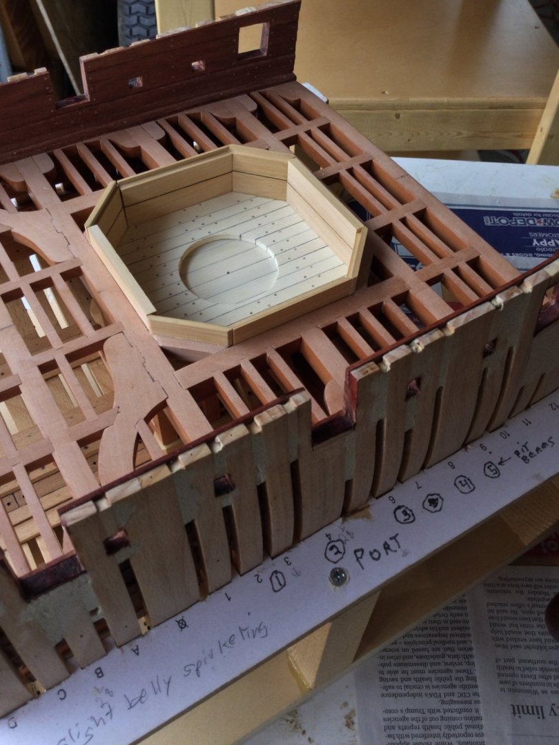
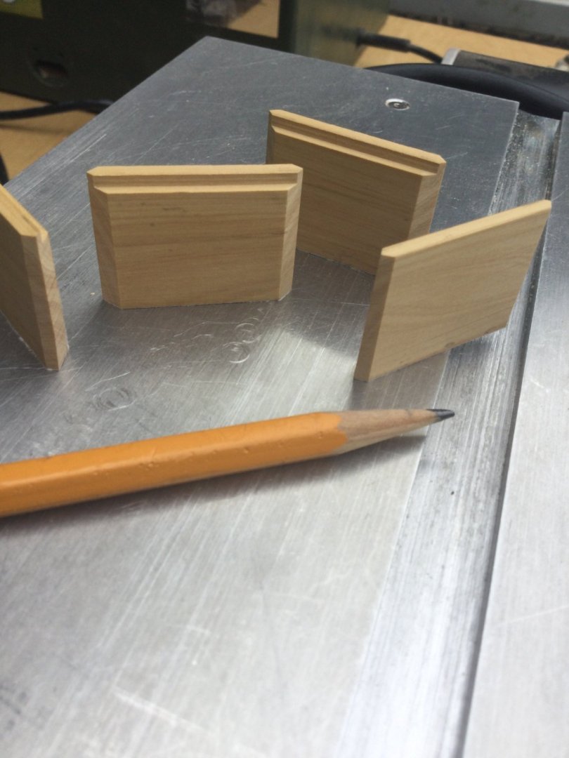
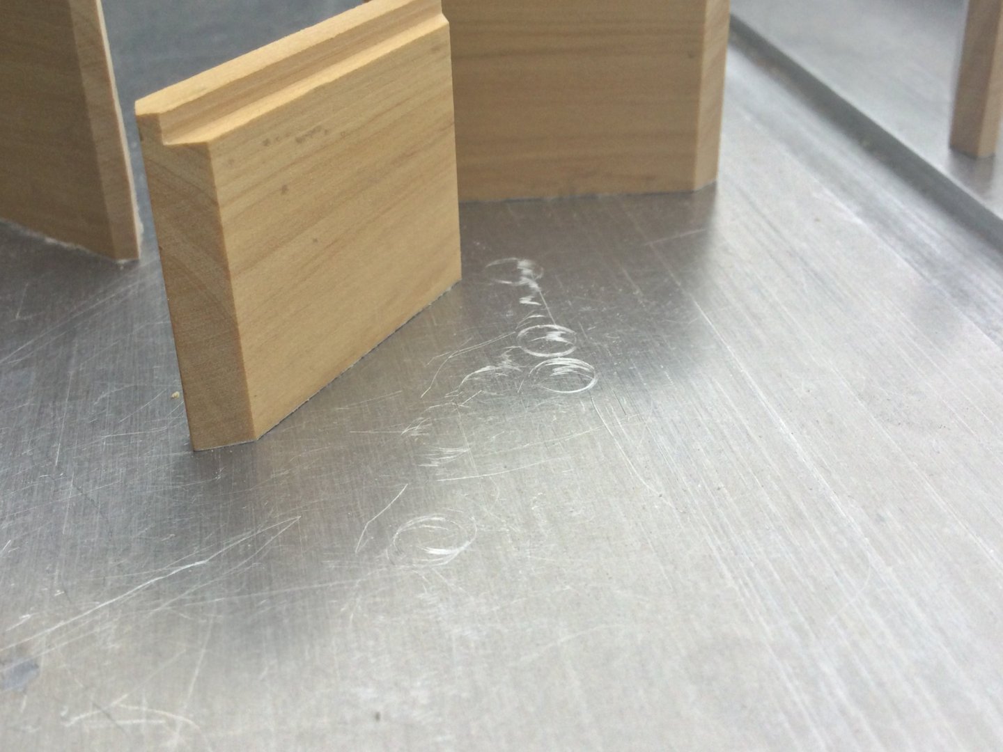
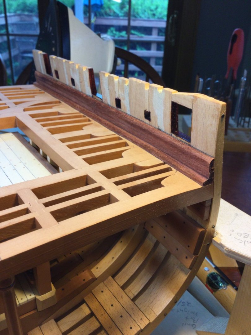
he diagonal bulkheads are the most difficult because there are two angles on each end that need to be cut to form a point. Fortunately, the andles are 45 degrees and the "point " is a 90 degree angle! I set my Byrnes disc sander table to 45 degrees and "cut" the angles very carefully. The photos show some finished bulkheads and how they butt up against each other. The rabbets are to accommodate the side covers, which are part of the mortar pit housing. I'm not sure if I'll include this!
- 143 replies
-
- 13
-
-
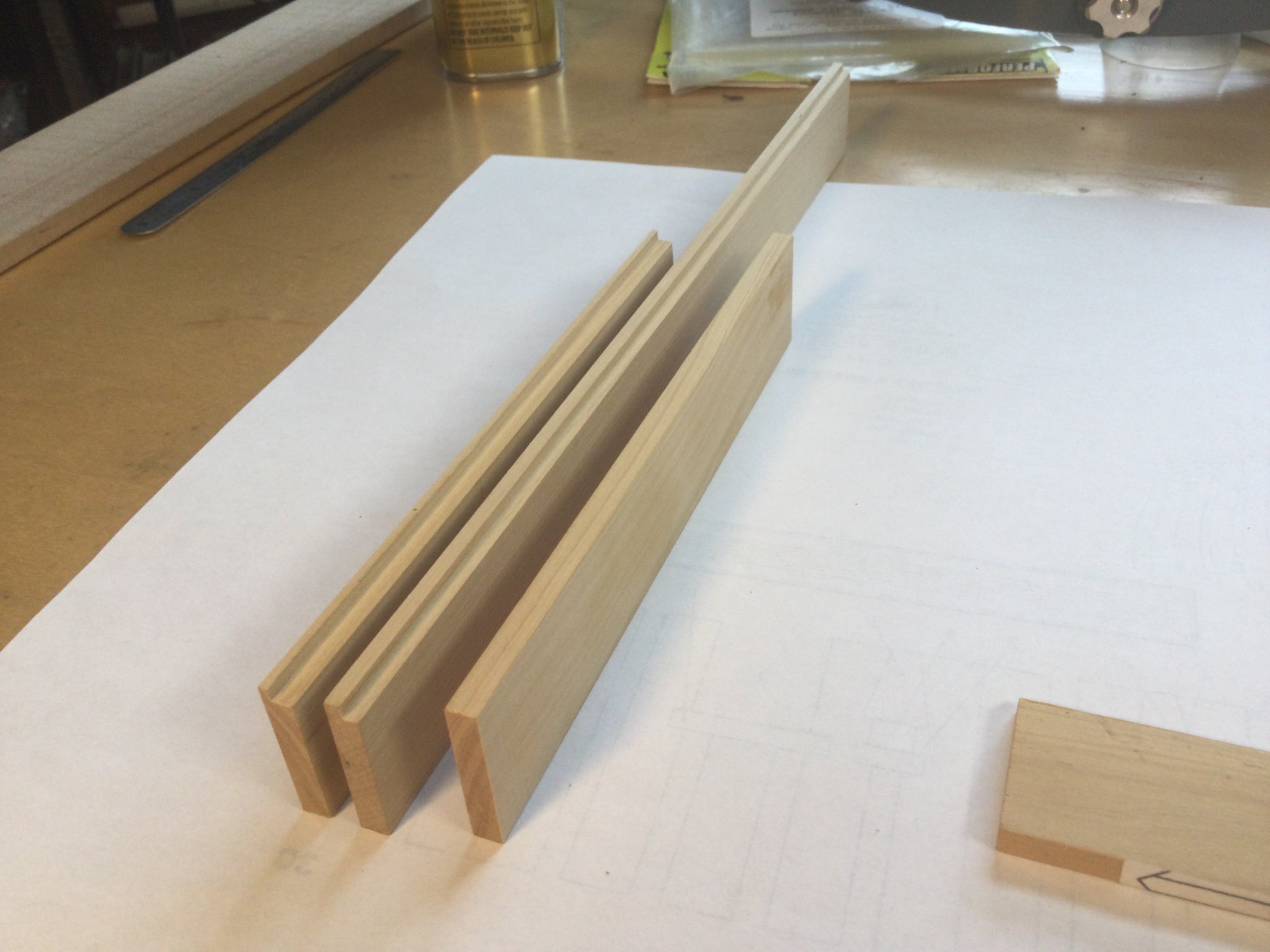
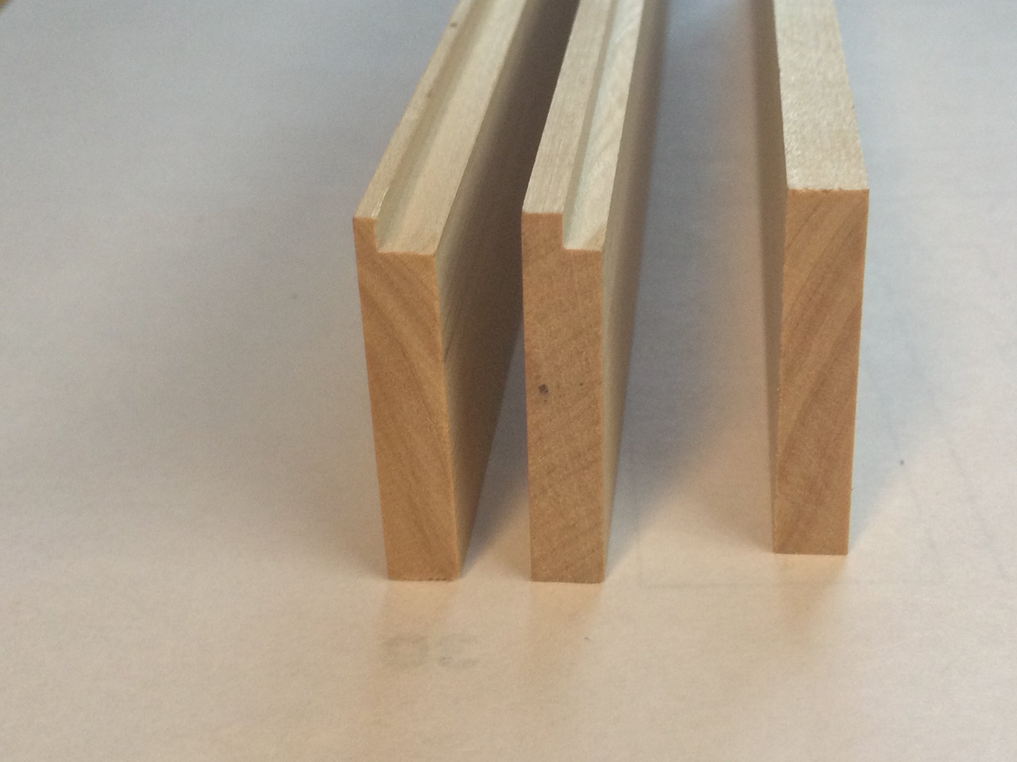
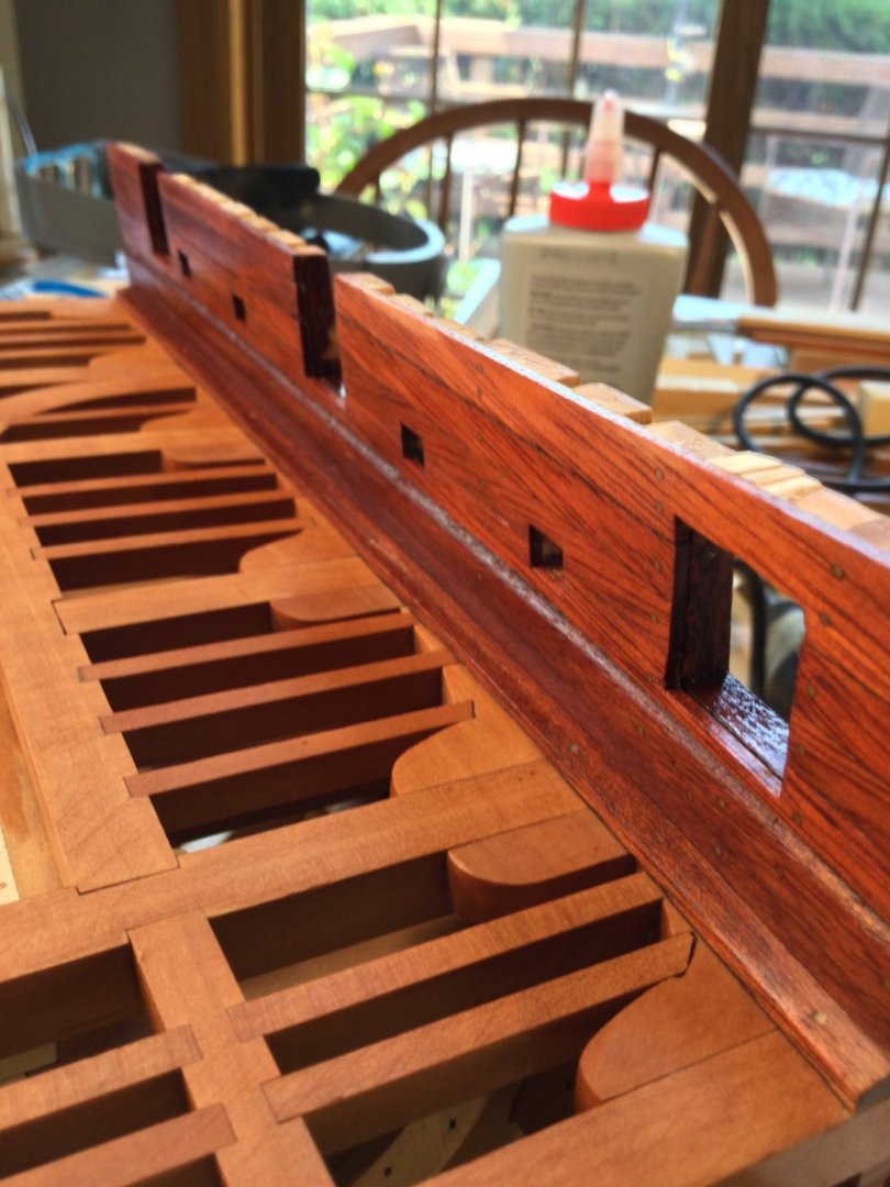
Thanks, guys! I started work on framing in the mortar pit by milling the bulkhead blanks out of boxwood. There are eight bulkheads, each 3/16" thick. The fore and aft bulkheads have no rabbet along the top edge, while the port and starboard bulkheads and the diagonal bulkheads do. The rabbet on the diagonals is 5/64" X 5/64". The rabbet on the port/starboard bulkheads is 5/64" X 1/8". The diagonals have complex geometry, which I'll do using the disc sander. I don't think this kind of precision could be reasonably expected except by using Byrnes tools!


- 143 replies
-
- 11
-
-
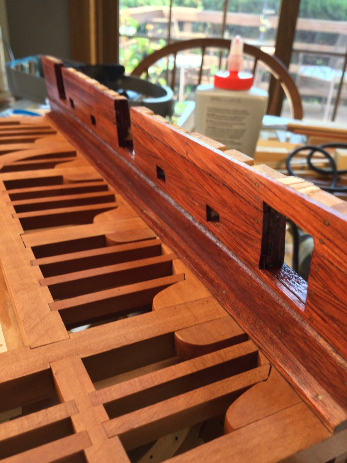
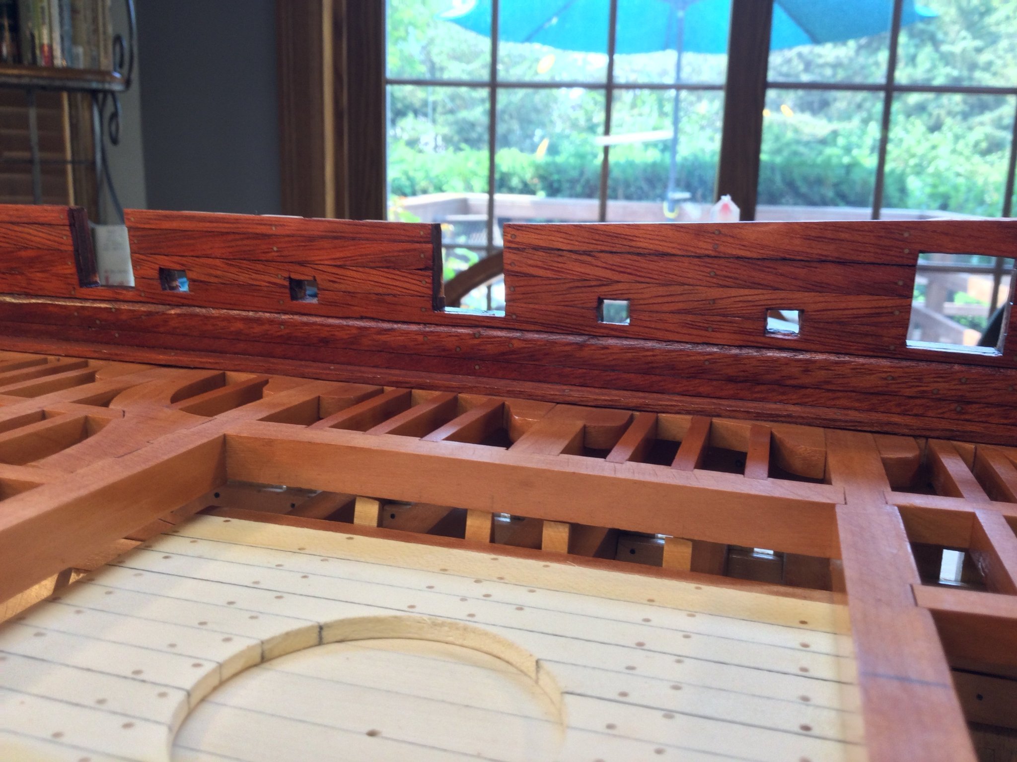
I'm back at it! I just finished planking the inboard bulwark ceiling planks, then cut the gun ports and the sweep ports. There are very subtle treenails in place. I used birch toothpicks and they blended in well with the bloodwood planking.

- 143 replies
-
- 14
-
-
Really beautiful, Elijah! I hope I can see her in person next year in Manitowoc!
- 228 replies
-
- 2
-
-
- gunboat
- model shipways
- (and 1 more)
-
Thanks, guys! Next I installed the spirketing planks. These are the two lowest planks of inboard bulwark planking. They are thicker than the upper inner bulwark planking and the topmost one is rounded over at it's upper edge. I did this using my Dremel mini-router table. The waterways and all inboard bulwark planking will be bloodwood.


- 143 replies
-
- 12
-
-
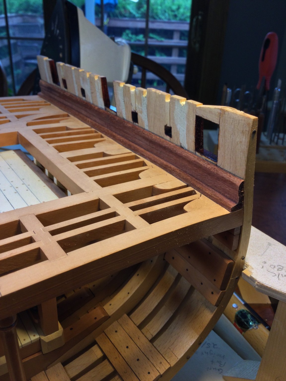
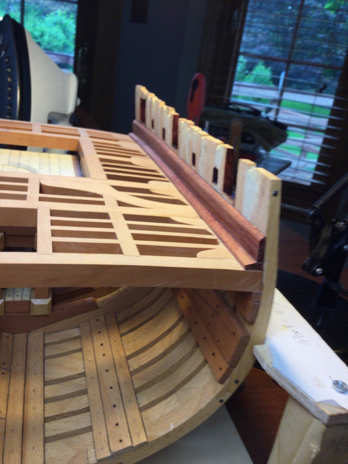
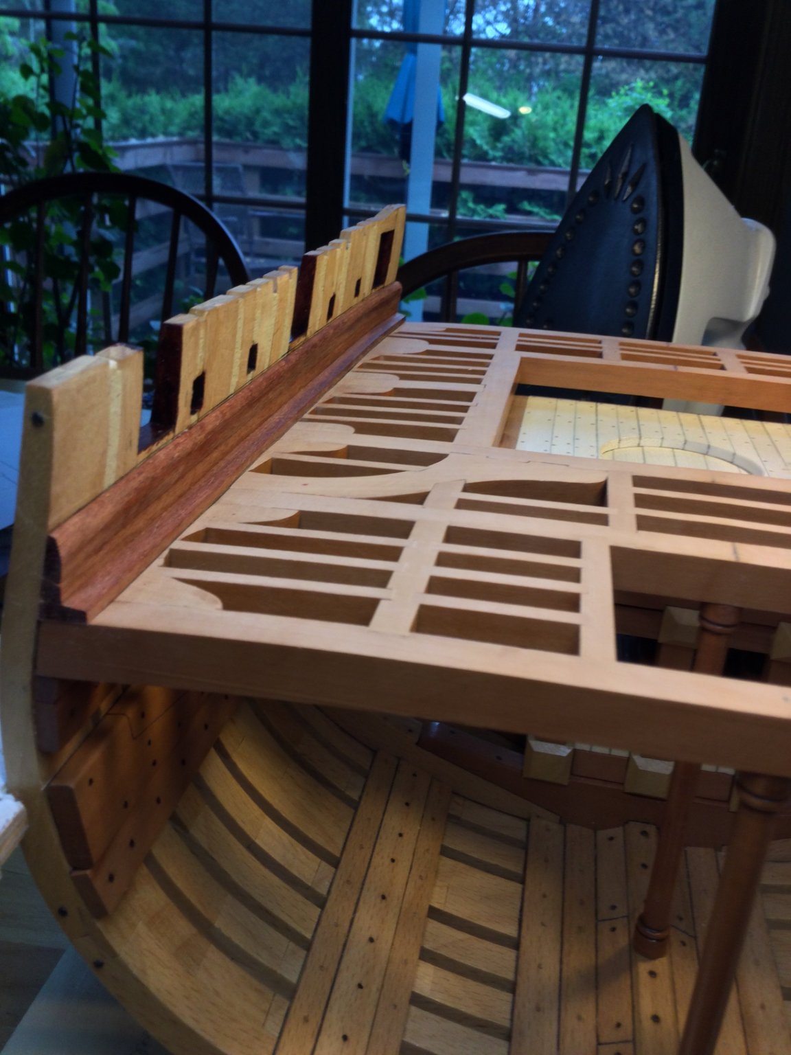
Thanks, Jean-Paul! I'm back in the shipyard but there are still tons of things to do around the house and yard. Hard to find time for everything! I cut the stock for the waterways. The two bevels (three, really) are a little tricky but they came out OK. The stock is a bit thick so soaking or using a clothing iron the bend the waterways to the narrowing beam at the aft of the model didn't work. My solution was a heat gun! I put a scrap of plywood on the bench top, then the waterway stock, then another narrow piece of stock on top of that. I clamped the "sandwich to the bech top and used another C-clamp to pull the waterway into it's curve. With it in position, I heated the waterway for one minute with mu heat gun, aiming at the spot noted by the arrow. The plank stayed curved with no spring back!


- 143 replies
-
- 14
-
-
Outstanding work!
-
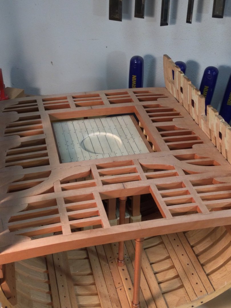
I finished the deck framing. No poly on the upper surfaces yet. Next up is working with bloodwood for the hatch coaming, the waterways and bulwark planking.


- 143 replies
-
- 13
-
-
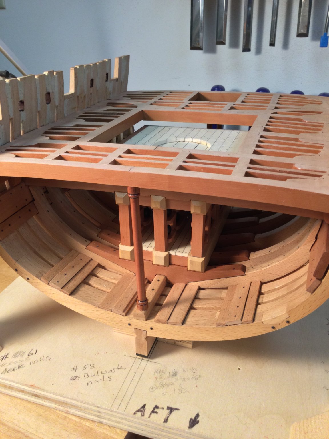
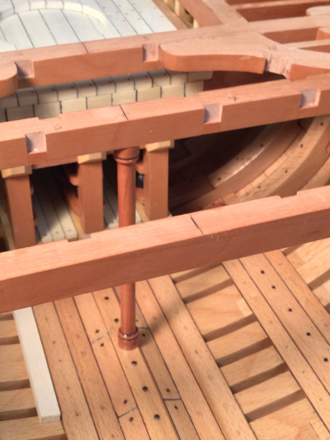
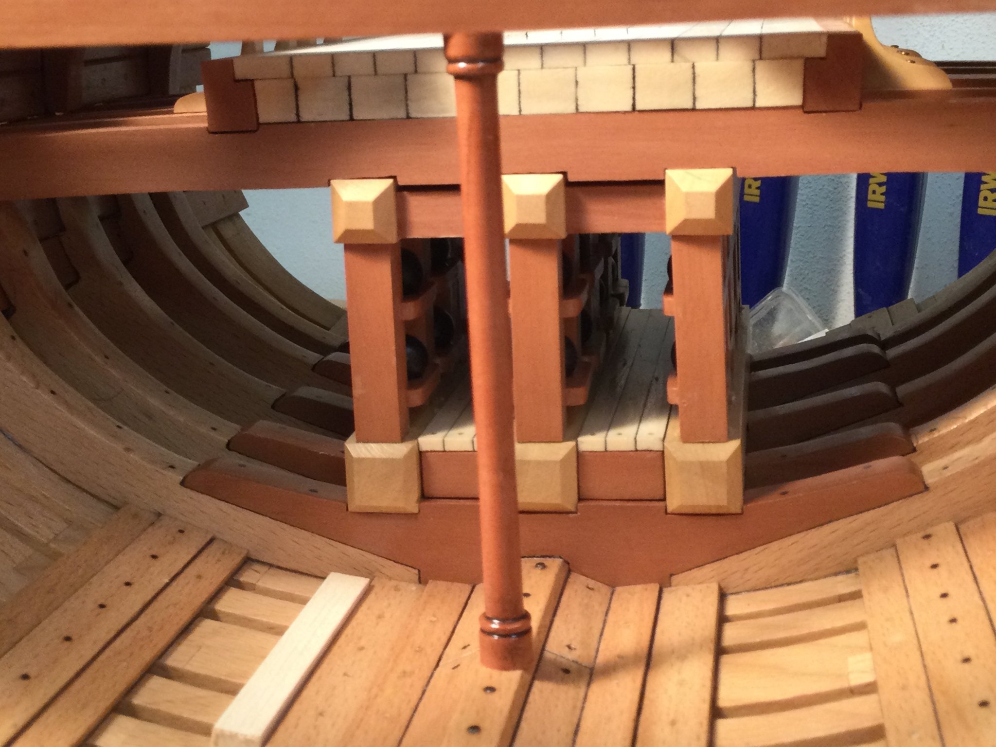
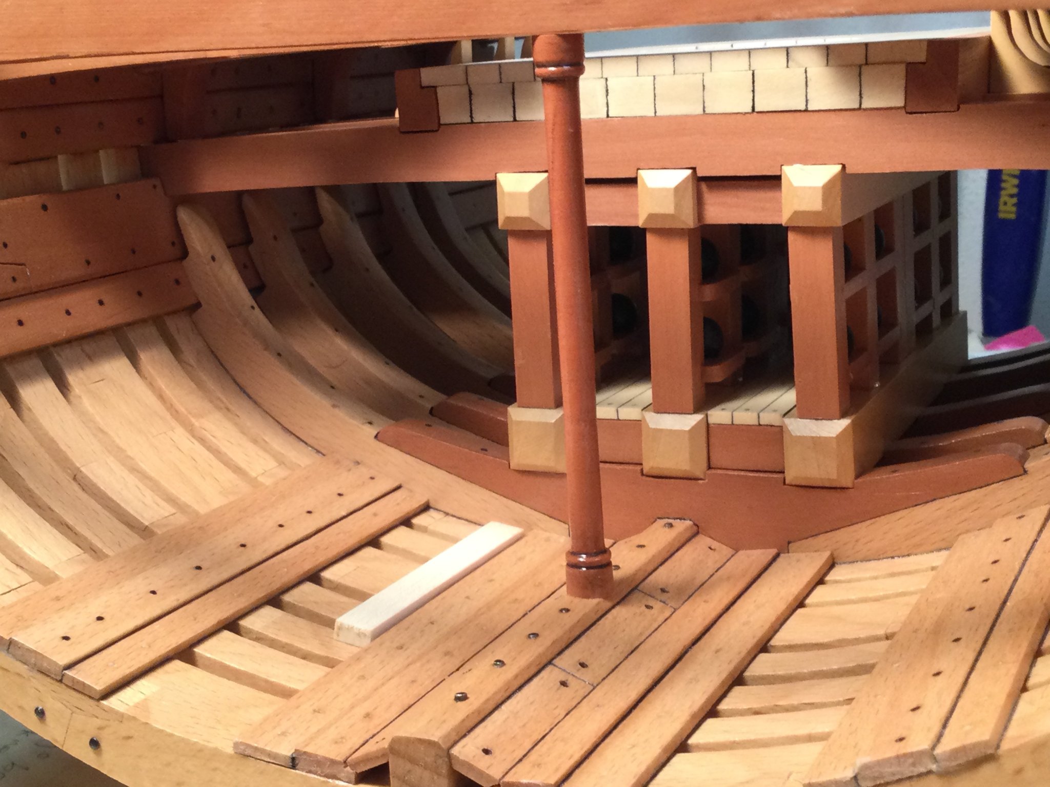
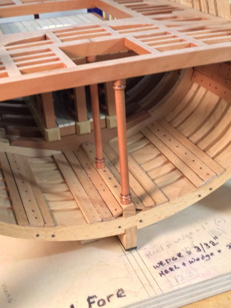
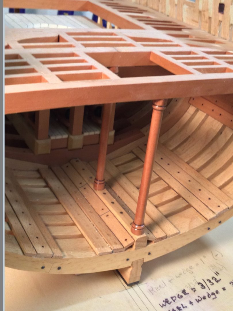
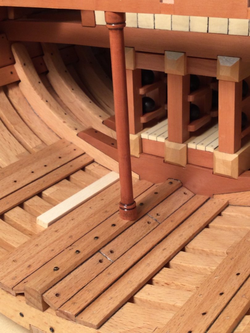
I cut the pillar under deck beam #2 to length. Here it is, dry fitted. I plan to pin it to the keelson and the deck beam. The piece of holly near the footwaling is just a measuring stick I used to locate the pillar on the keelson


- 143 replies
-
- 11
-