DocBlake
-
Posts
1,811 -
Joined
-
Last visited
Content Type
Profiles
Forums
Gallery
Events
Everything posted by DocBlake
-
 Fitting the riders and cutting the top timbers to allow the upper and lower mortar pit clamps to fit was a real bear of a job. I spent more than 10 hours on this part of the build! The fit of the rider top timbers against the clamps isn't as tight as I'd like, but much of the detail will be obscured by the deck framing. The clamps are sitting in place, ready to be installed permanently.
- 143 replies
-
- 12
-

-
Great progress. A fine model, very well done!
-
Really nice work, Yves! She is just gorgeous.
-
Very nice work, Yves!
-
Very well done! Congratulations!
-
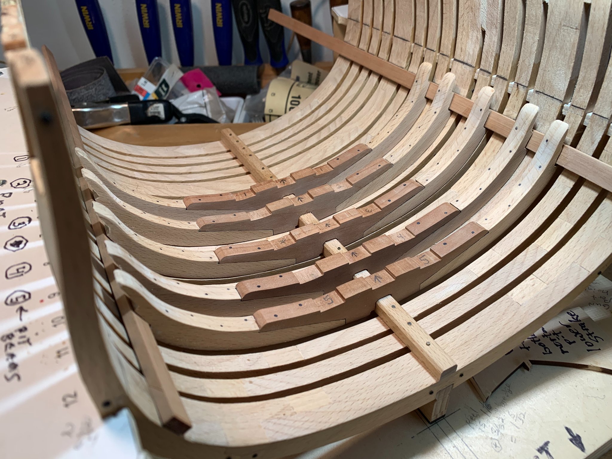
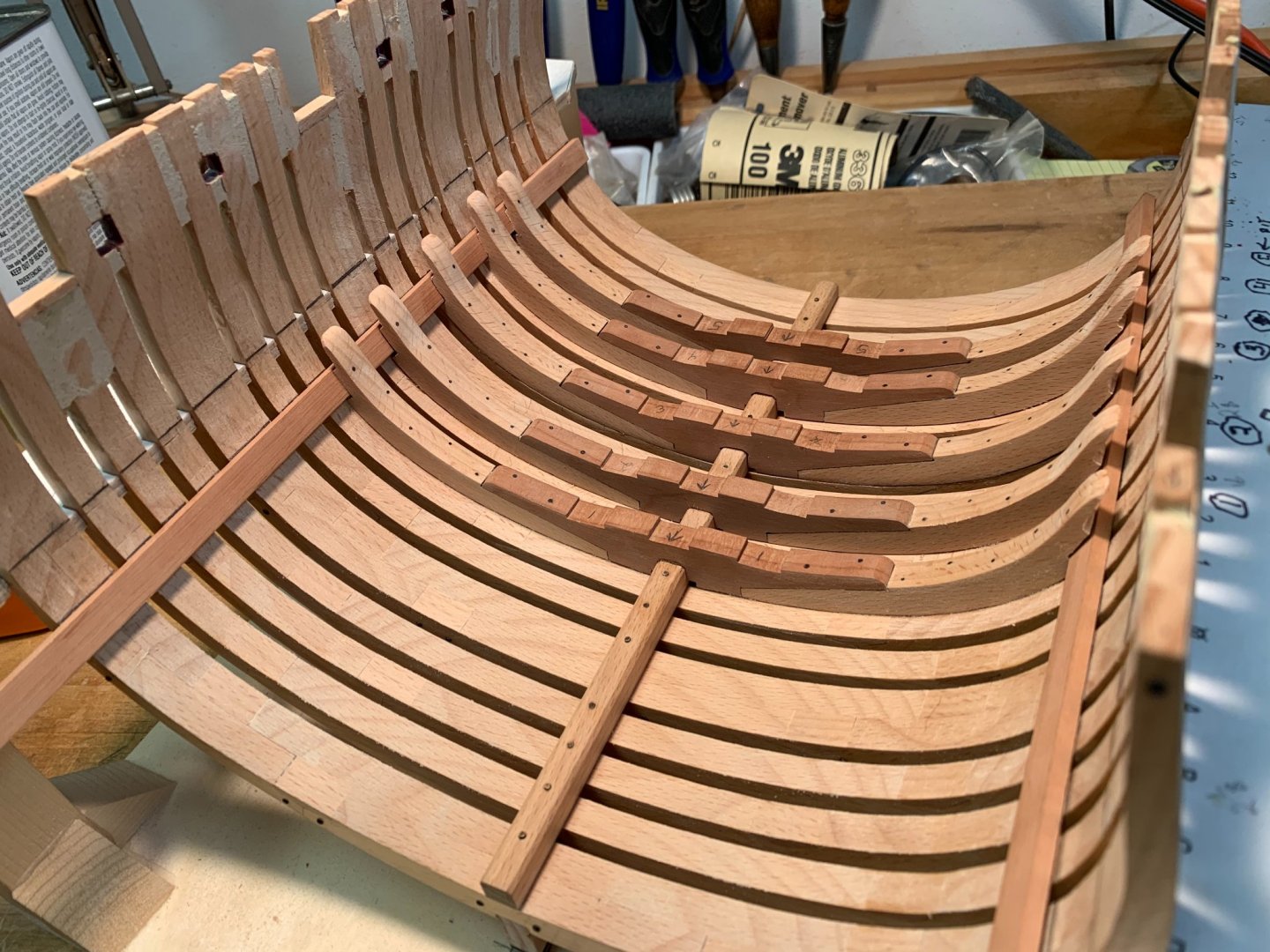
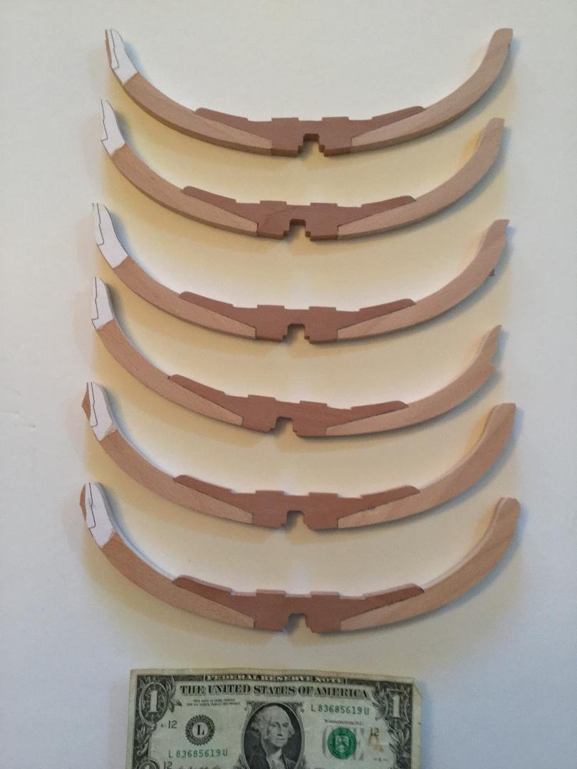
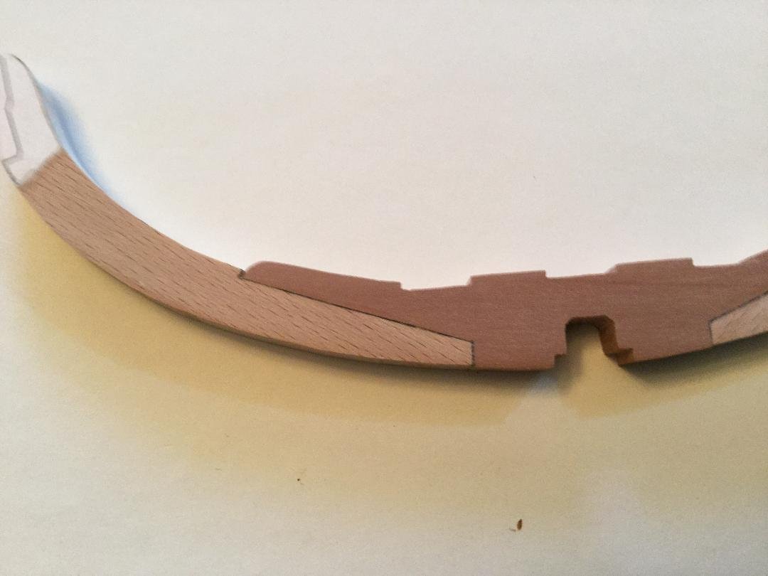
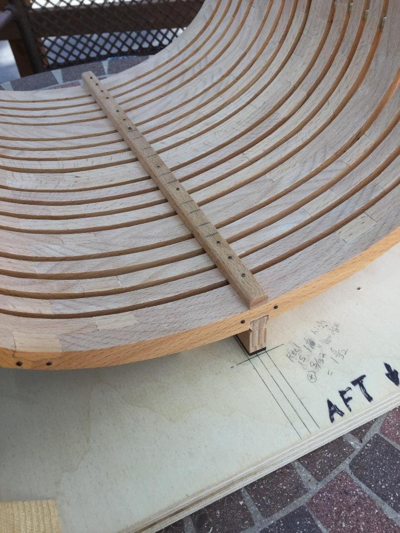
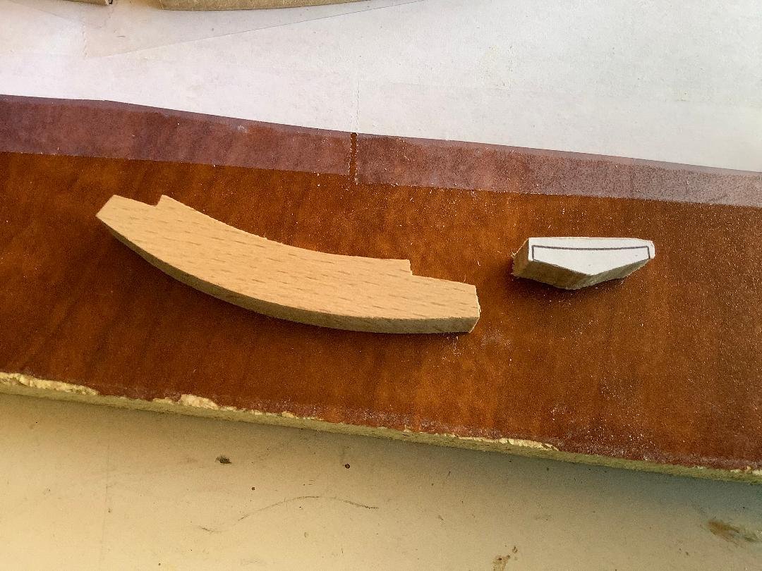
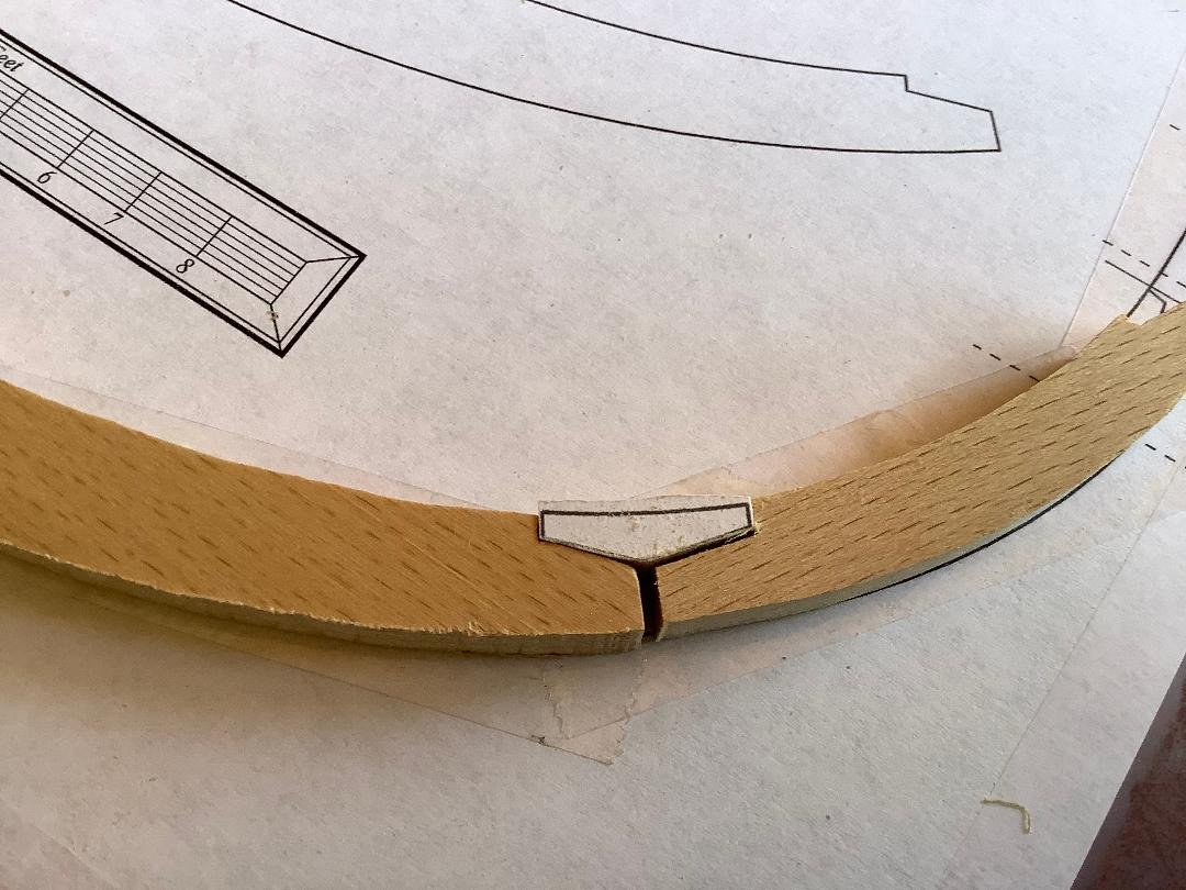
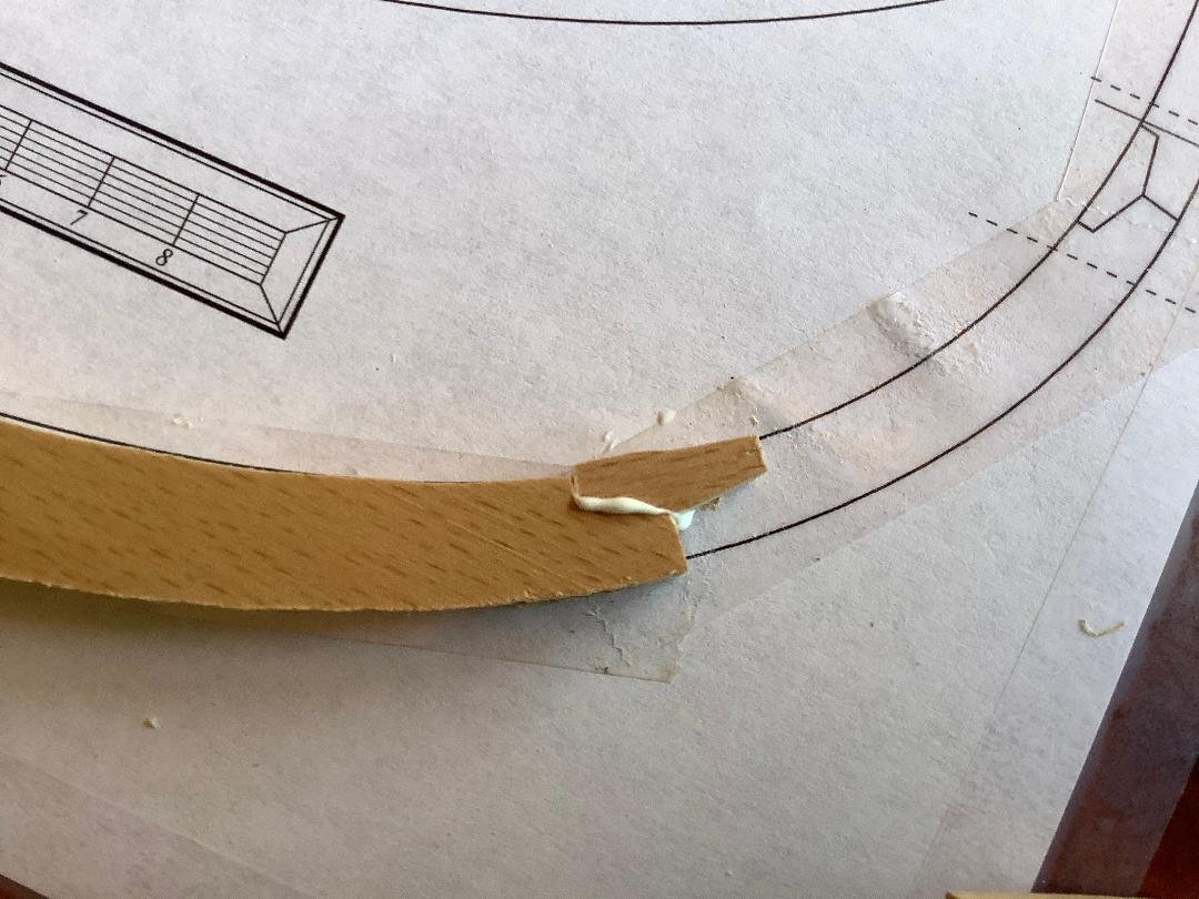
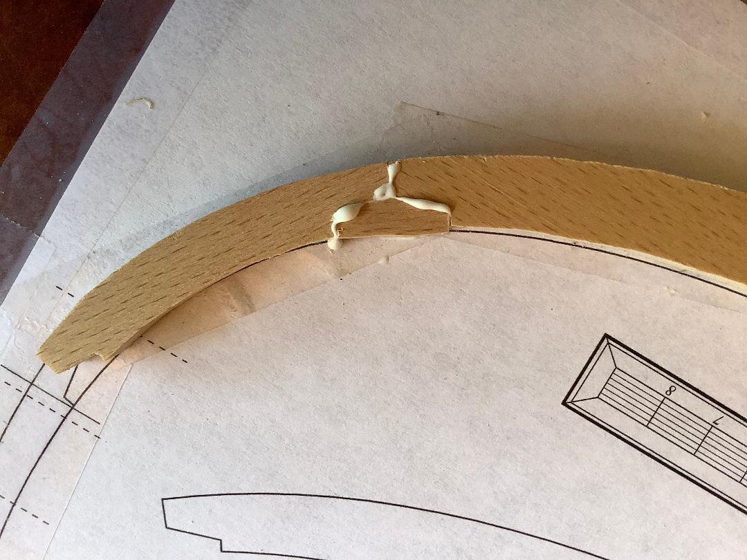
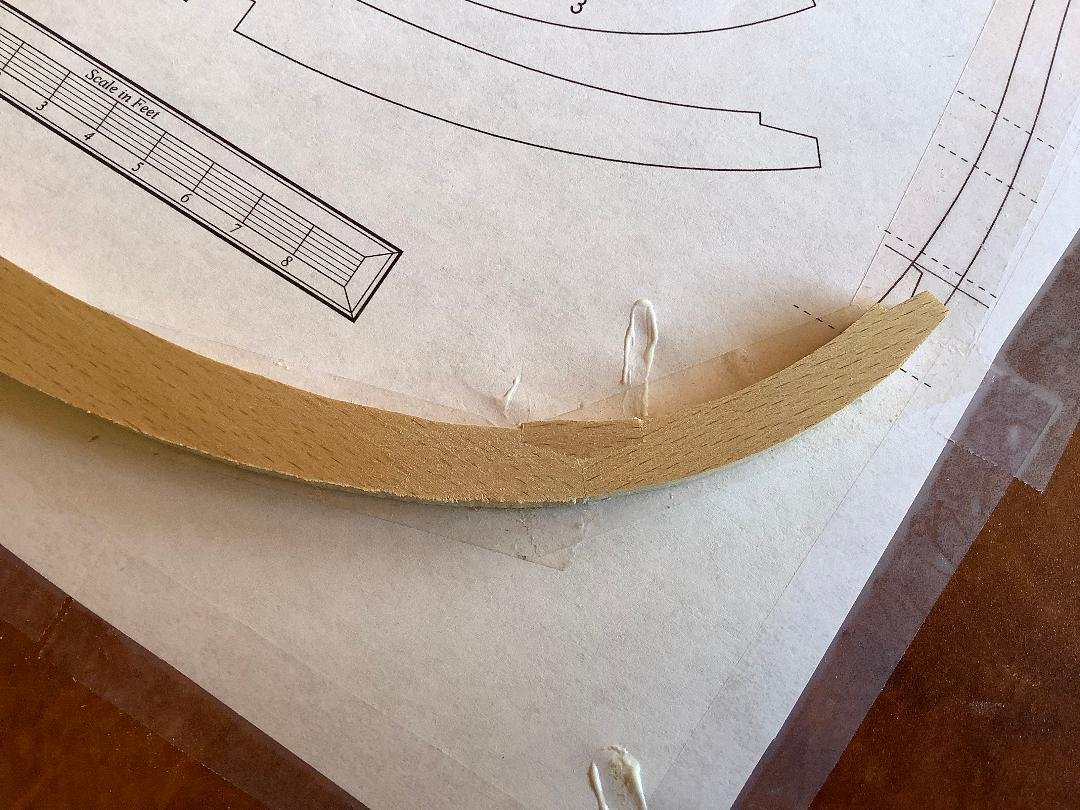
There are 5 floor riders that reinforce the frames under the mortar. I made six! I used swiss pear and beech for a little contrast. The riders sit on the keelson and hug the frames and then overlap the mortar pit deck clamps. The plan shows the location of the riders on the keelson. As you can see, I’ve yet to cut the outline of the top of the riders that overlaps the clamp strakes.

- 143 replies
-
- 11
-
-
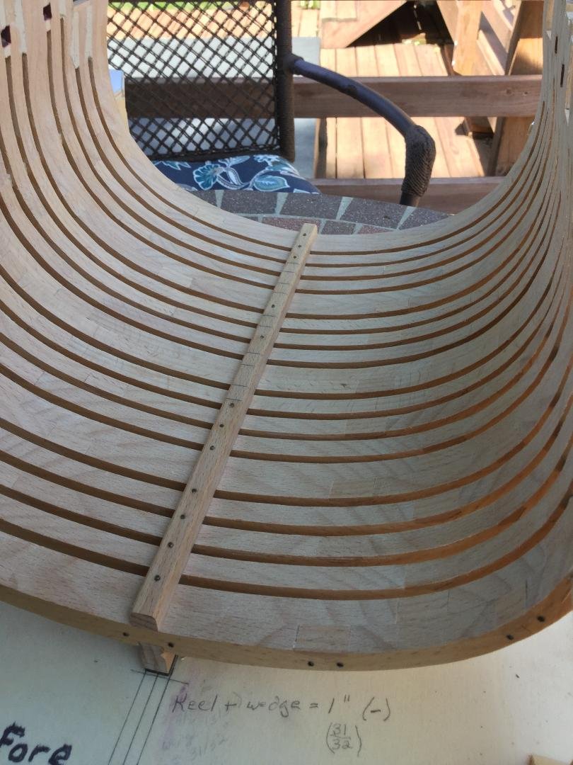
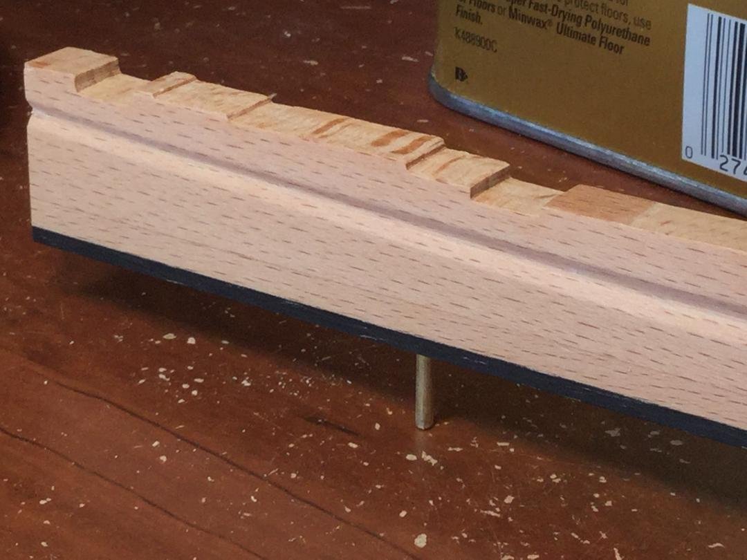
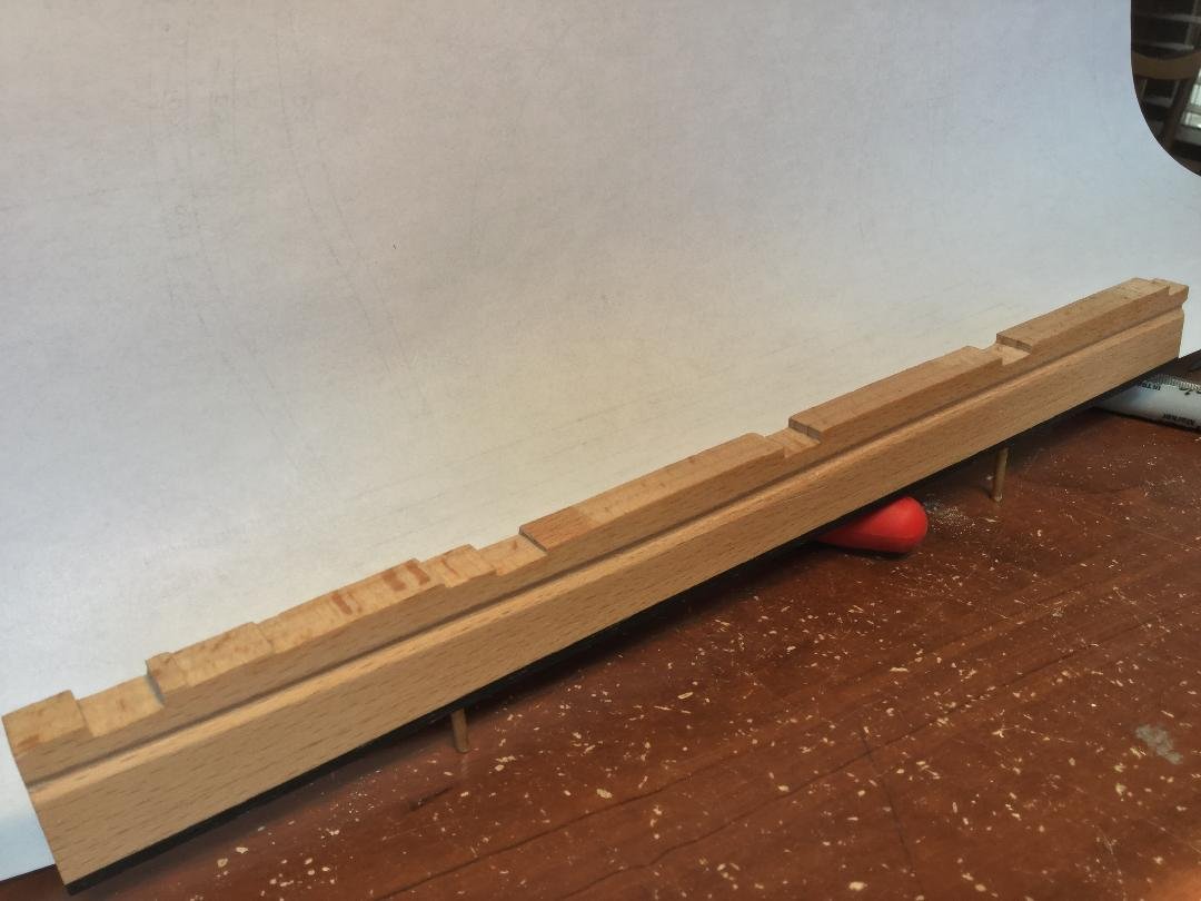
The keelson was glued in place using Weldbond. The pencil lines are the locations of the five floor riders that help support the mortar. The bolts are darkened 18 gauge brass nails.
- 143 replies
-
- 10
-
-
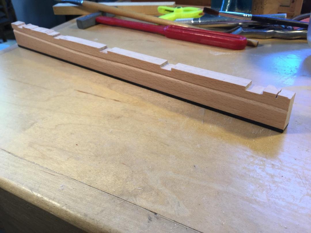
I cut the keelson blank a bit long and then milled the two bevels on the top surface. I then tapered the aft end to match the rise of the final four frames on the keel/hog. I then cut the keelson to length.
-
Thanks! I used temporary spacers to make sure the frames sat properly on the hog or rising wood. The double frames are constructed so that half the frame sits a little deeper than the rest of the frame. The frame locks in place. It can’t move once seated. I then used epoxy the glue ar the frames in place and faired the inside of the hull. The spacers above the waterline are glued in place. The hull is strong enough to remove the transverse support of the jig top for and aft. Makes it easier to work inside!
- 143 replies
-
- 12
-
-
I installed model railroad spikes as bolts in the double frames only. Once that was done, the frames were given 3 coats of poly on their fore and aft faces. I used spacers above the waterline between frames and glued them all to the keel and hog. Each frame had a spreader bar that attached to the top timbers by those little yellow nails. No glue!
- 143 replies
-
- 12
-
-
Some photos of the chocks in a finished frame before sanding. I use a variable speed Dremel on low to sand the chocks and finish with flexible sanding blocks by Norton
- 143 replies
-
- 10
-
-
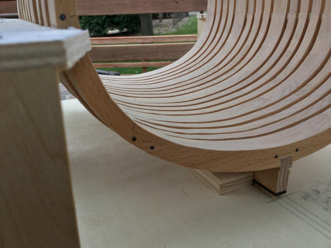
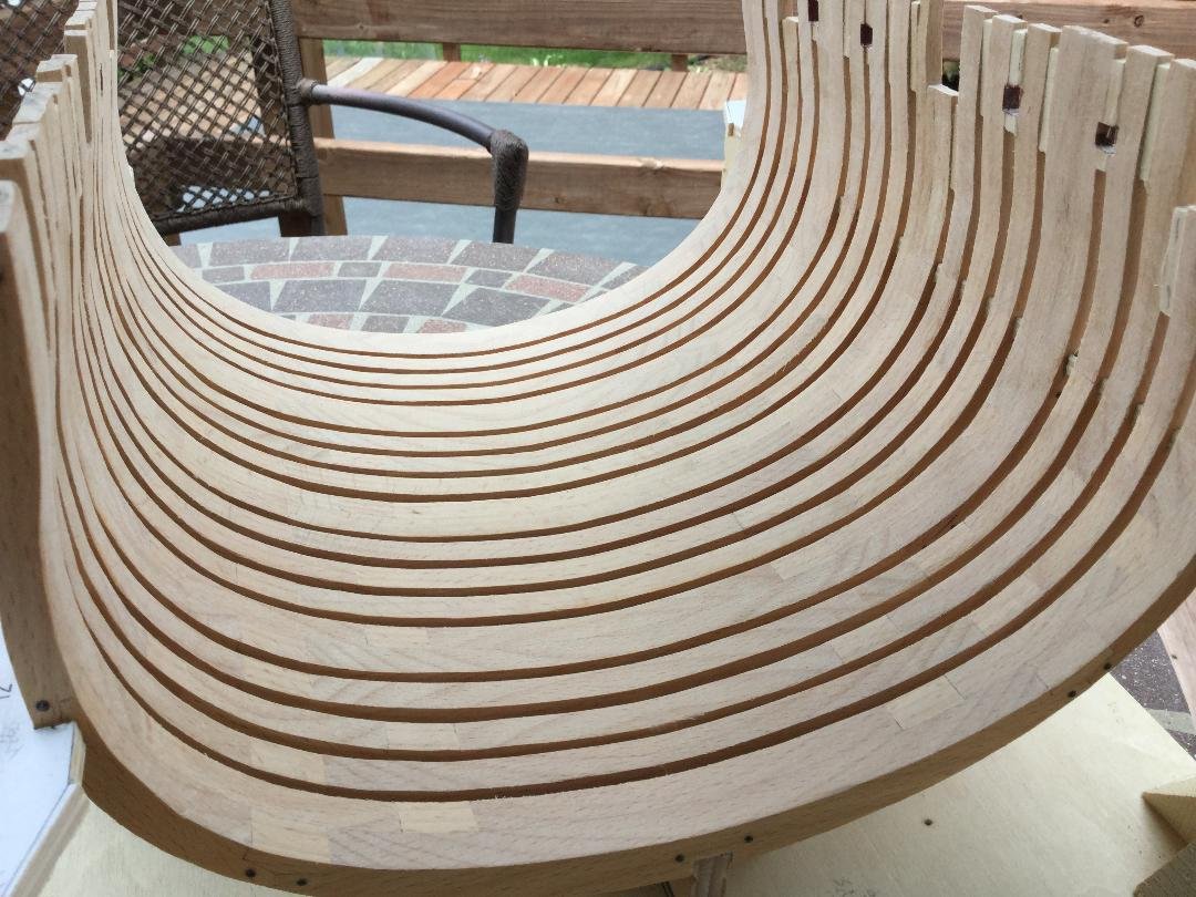
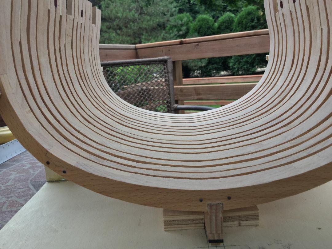
With the keel completed, I turned my attention to constructing the frames. There are 17 in all – 5 double frames and 12 single frames. The are assembled using typical chock and scarf construction. Because of the style of the joints, they must fit very tightly, because there isn’t much gluing surface and part of it is end grain, so the frames could be fragile. Still. It’s possible to get pretty tight joints. The trick is to make the chocks oversize, and sand/file them to fit first into one scarf and then the mating scarf. The photos show the sequence.
- 143 replies
-
- 12
-
-
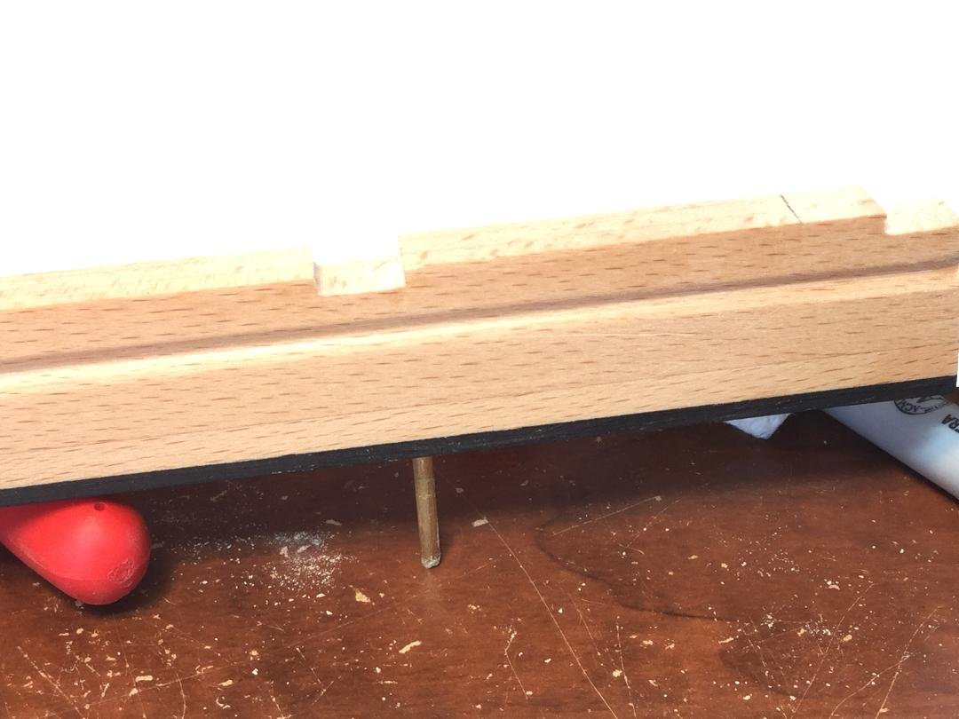
The first part to make is the keel assembly. Jeff's plans call for this to be constructed of 4 separate parts: The hog, keel, upper false keel and lower false keel. I decided to make the hog, or rising wood, part of the keel. The keel /hog assembly, and the upper false keel are European beech, the lower false keel is ebony. There are notches cut into the hog for the various frames. I was able to do this on my Byrnes saw, but it would have been far easier with a mill. You can see the notches rising at the aft end of the keel. The last task was cutting the rabbet. The keel assembly is fixed to the build board by brass rods and is removable.
-
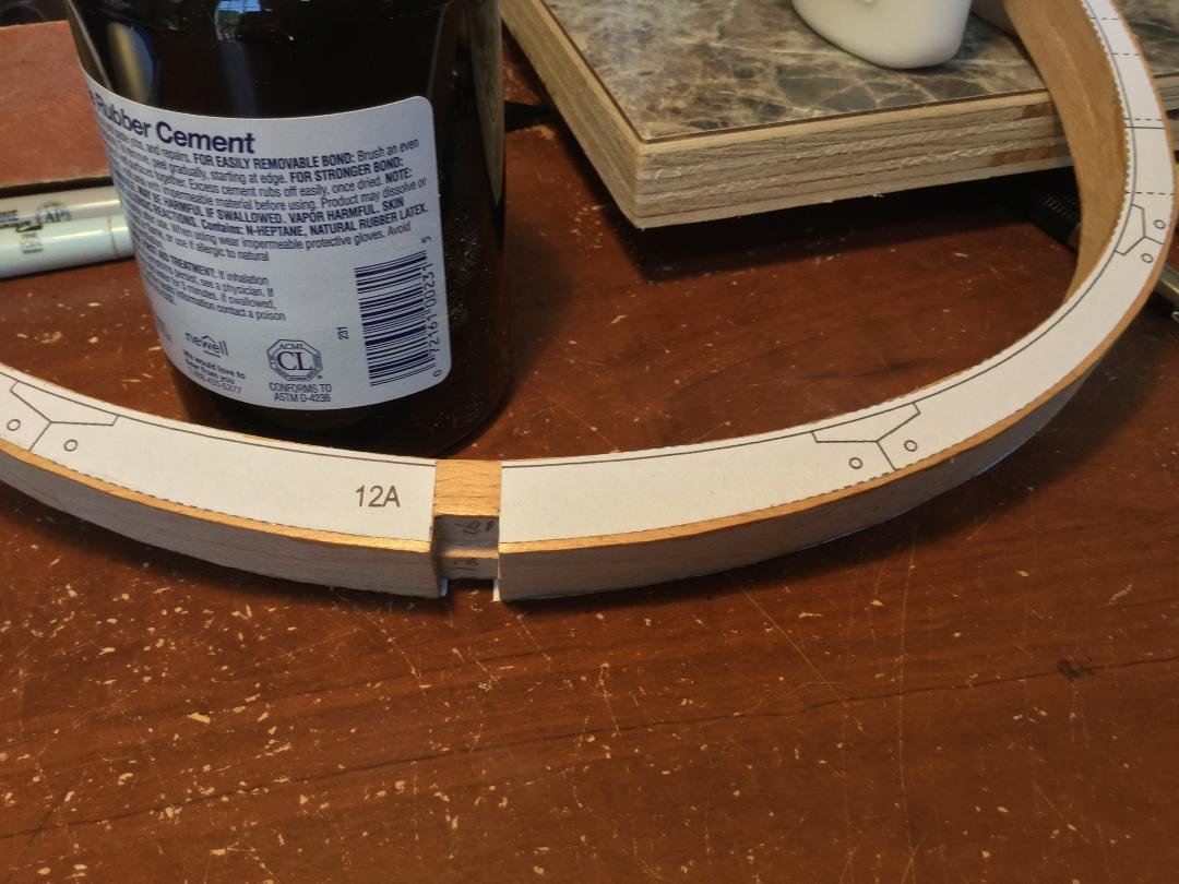
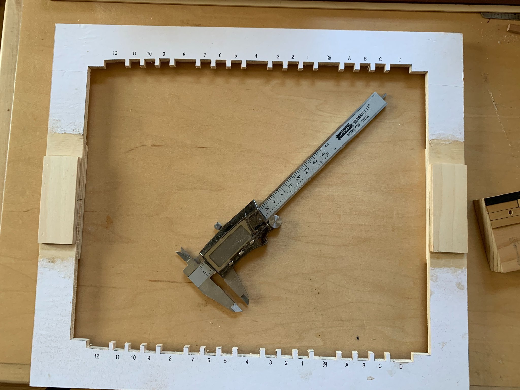
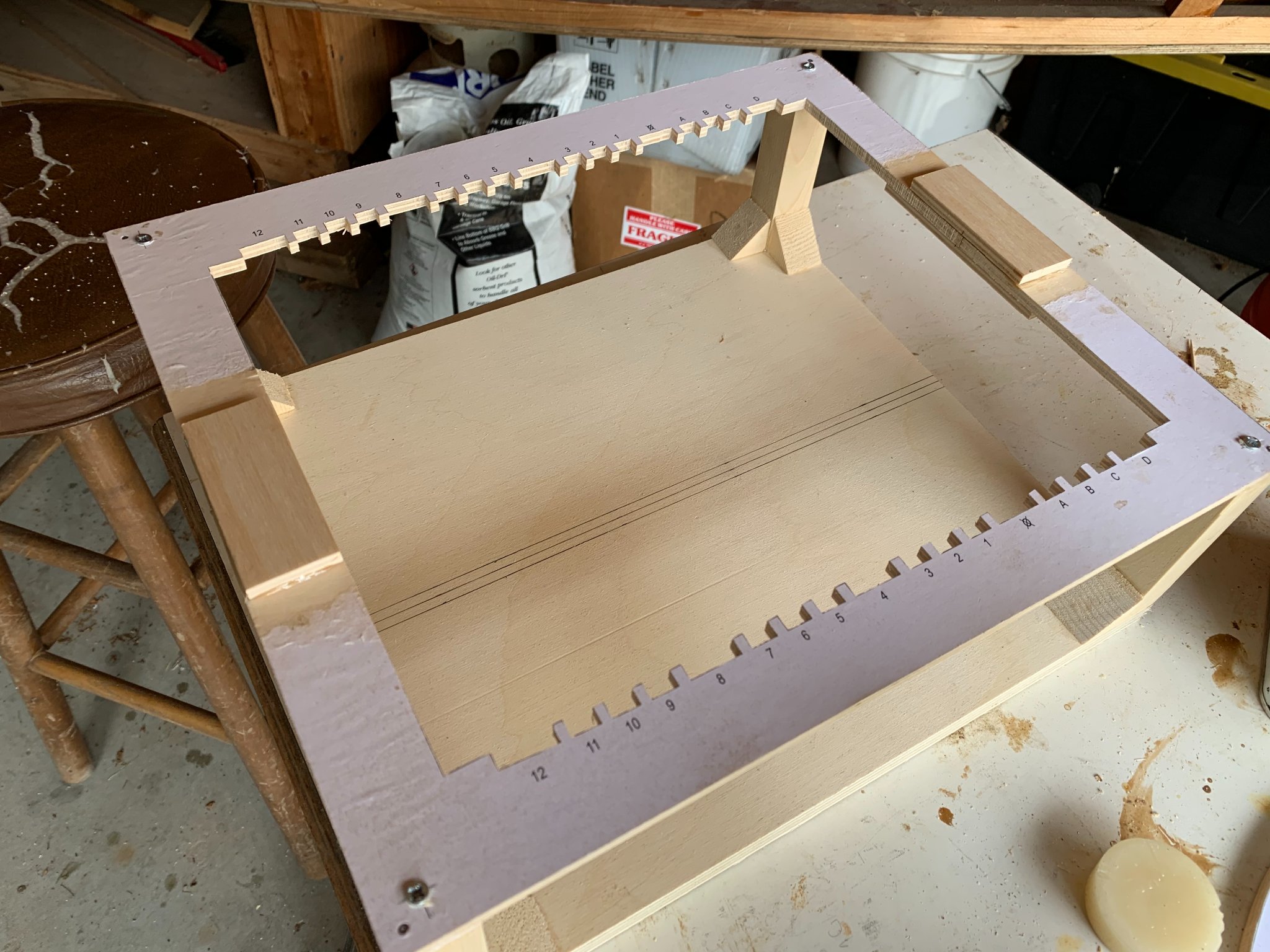
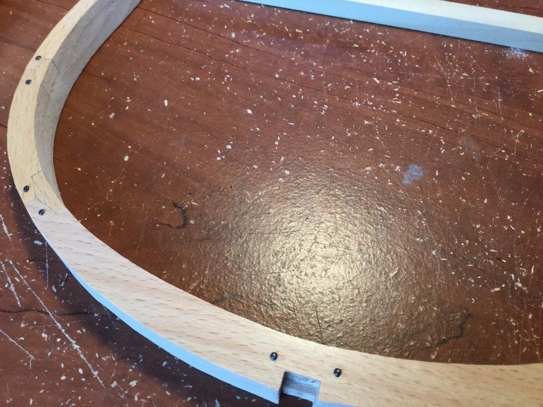
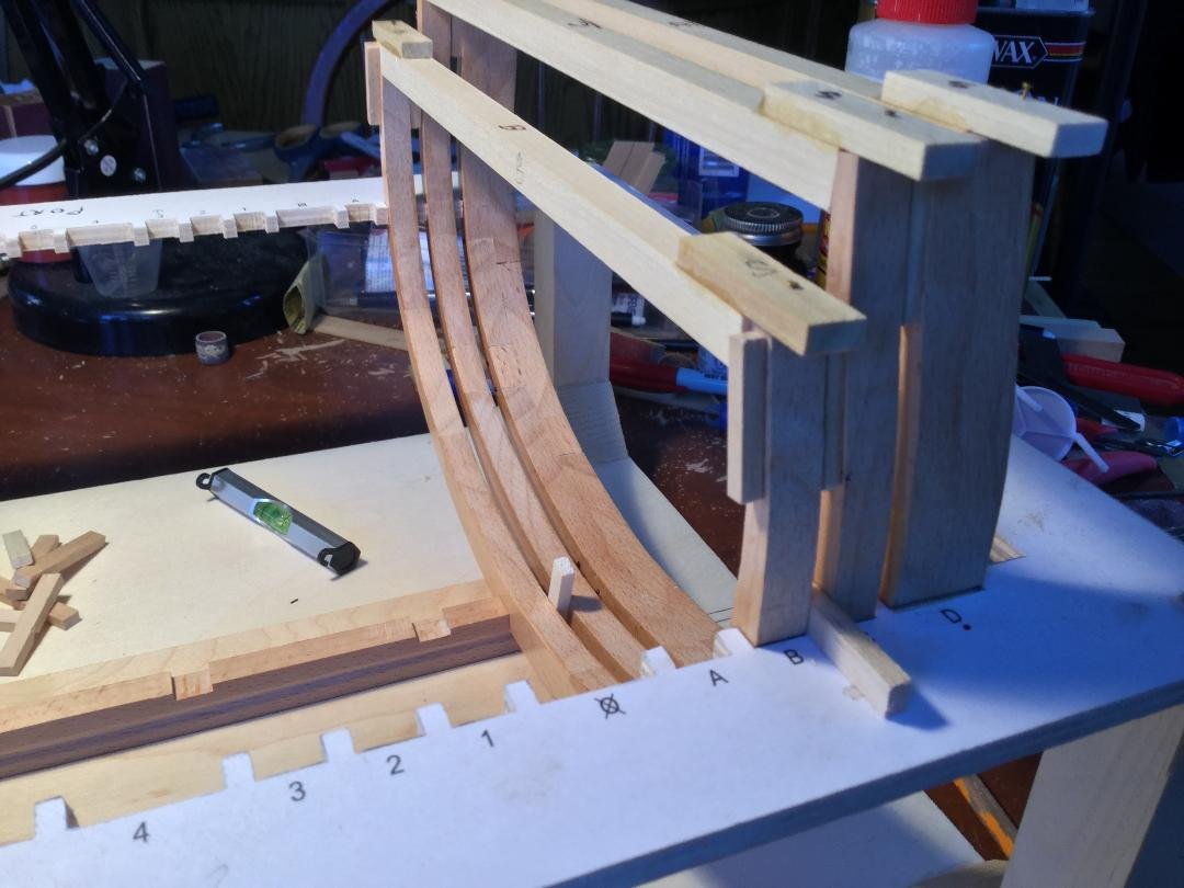
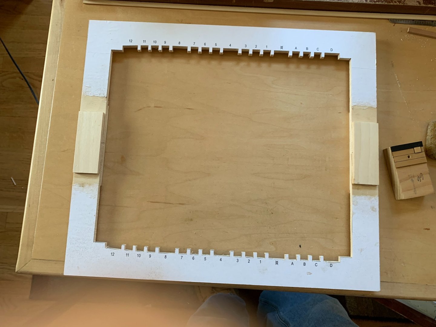
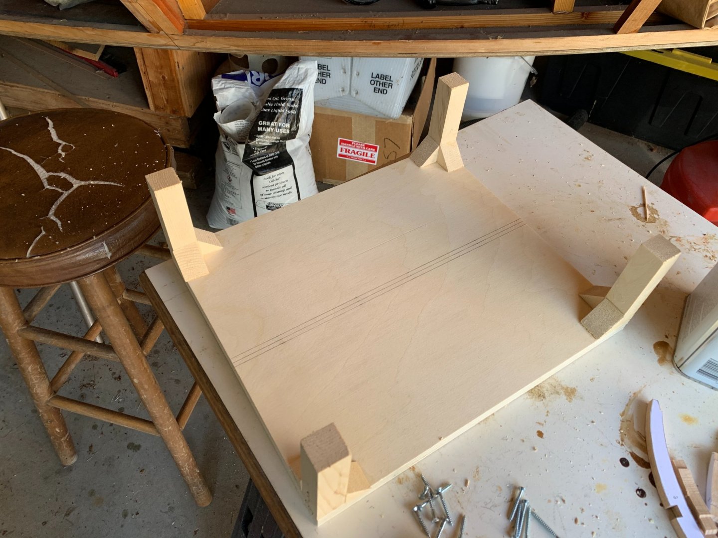
Thanks all! The jig is upright, like my Blandford and POF Armed Virginia sloop. The plans for the jig top lay it out in two pieces, joined at the midline. Proper alignment is important. The first step is to use spray adhesive to attach the jig top template to some ¼” plywood and then cut out the center part and form the notches that hold the frames in place. There are 5 double frames and 12 single frames – 17 in all. The run of the frames moving aft is pretty straight except for the last few which begin to turn inward, narrowing the hull. The last three frames also rise on the hog. The jig top is positioned on 4 supports that hold the top such that the top surface of the jig top coincides with the load waterline.


- 143 replies
-
- 11
-
-
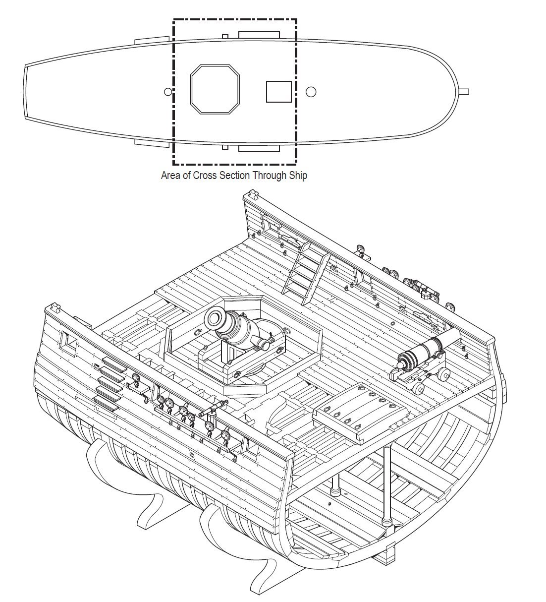
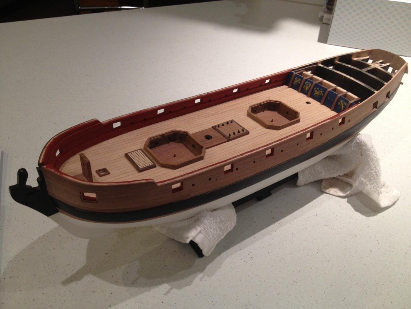
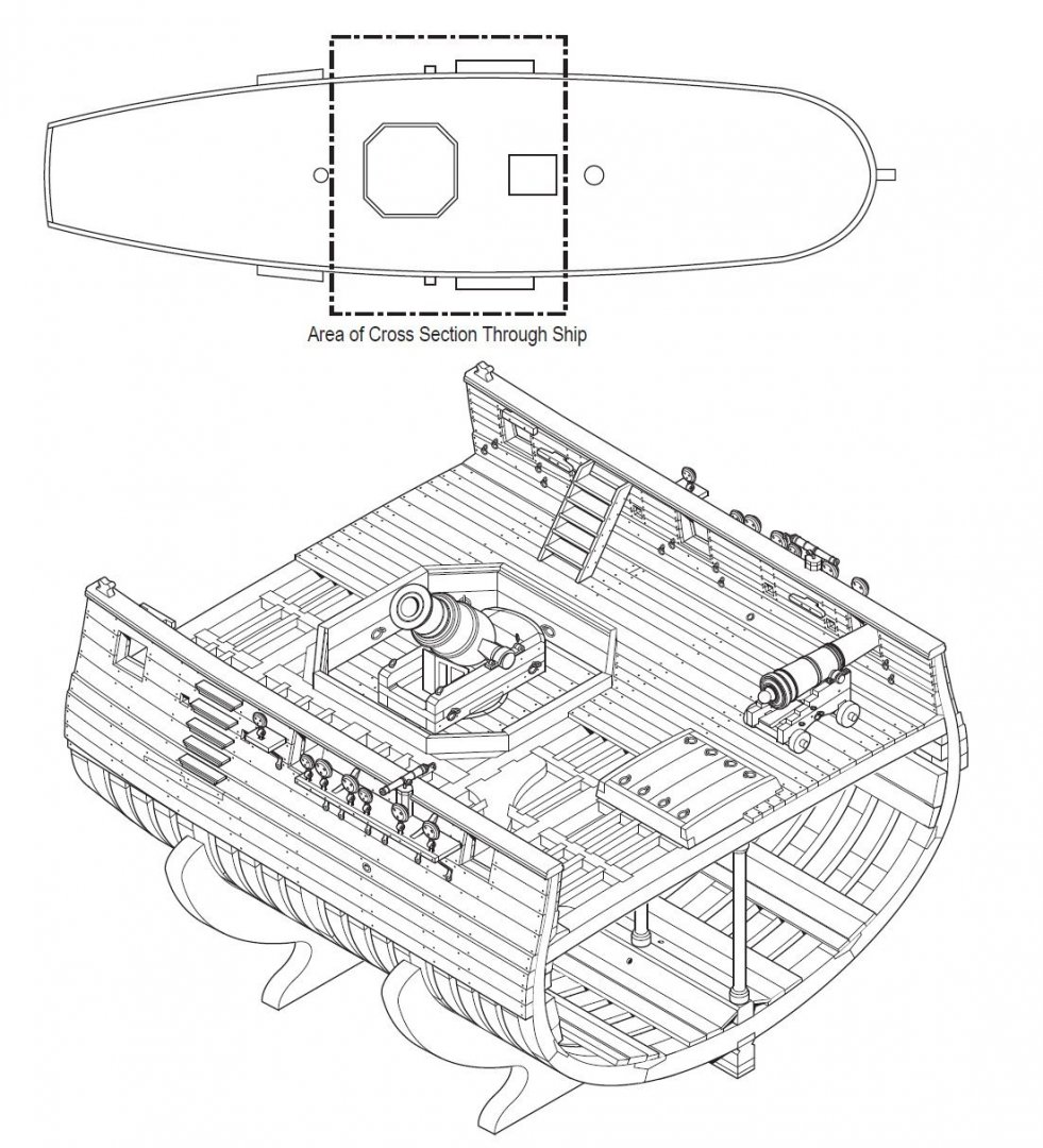
The second mortar was forwad of the main mast. Here's a shot of the deck showing the two mortar pits from Timmo's log :
-
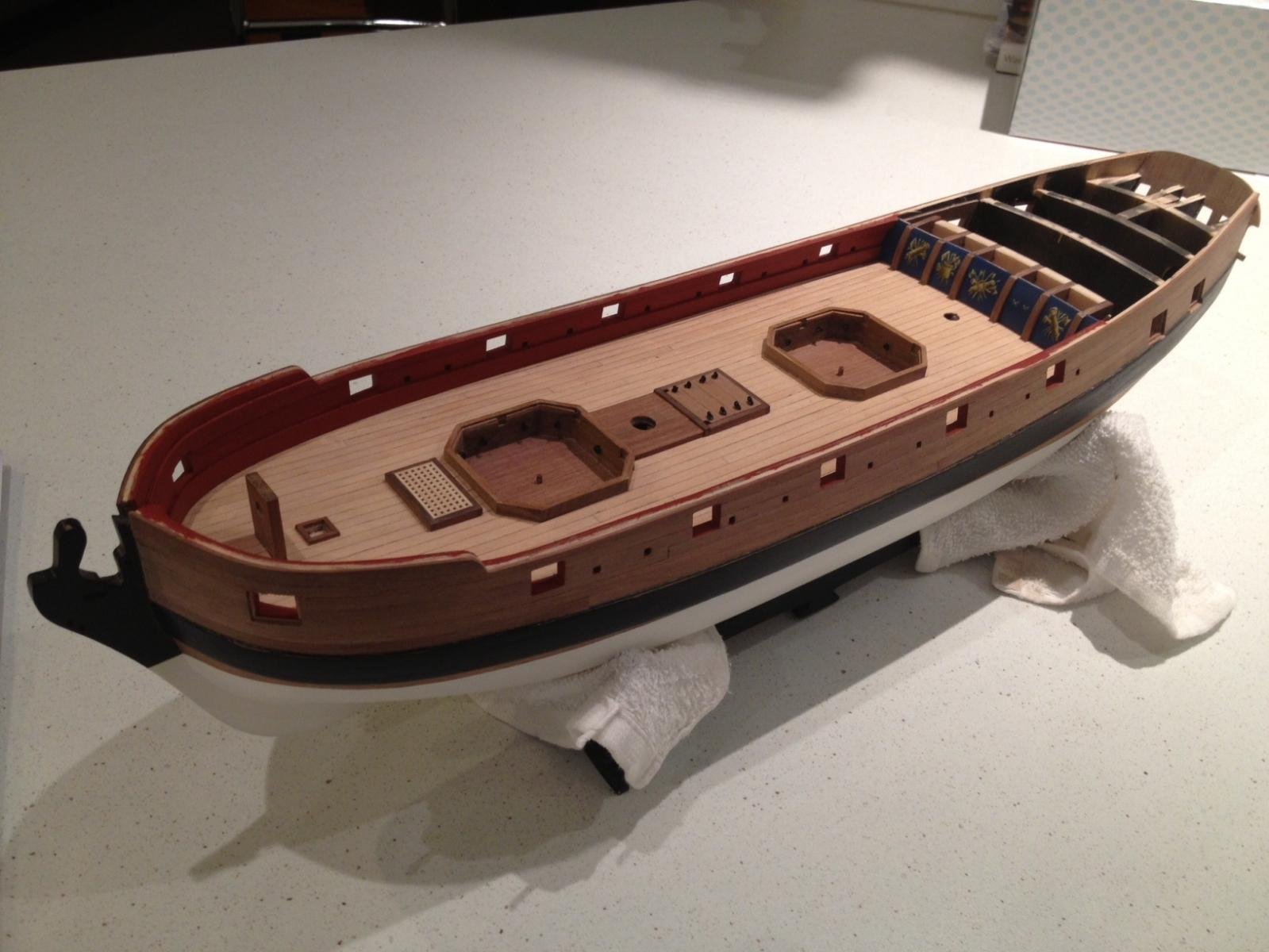
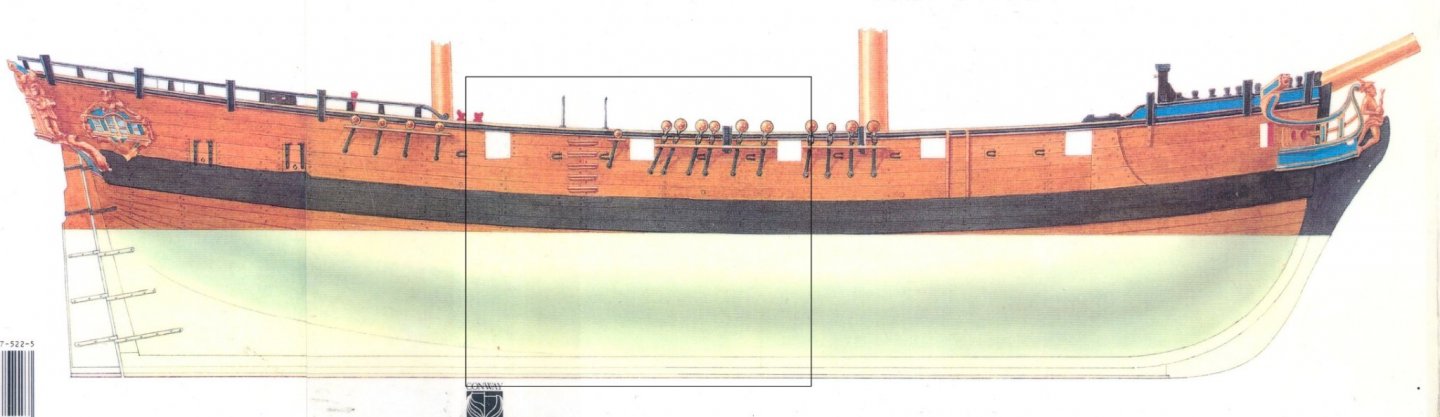
This is my log for my scratch build of a cross section of the bomb vessel HMS Granado. The plans were drawn by Jeff Staudt and were based on Peter Goodwin's AOTS book, which I plan to use as a reference. The section is from the center of the ship and includes 3 gun ports on each side, and a pit for a 13" mortar, one of two mortars on board. The rectangle in the image shows the location. I purchased the plans in 1/24 scale, but that is clearly too large for the space the Admiral has alloted for the model so I'll build her in 1:32 scale. Even at that reduced scale, the model is 7-1/2" high, 10" wide and 10-3/4" long! Granado was one of a dozen bomb vessels, or mortar-armed ships built by the Royal Navy between 1740 and 1742. She was launched at Ipswich on June 22, 1742. The vessel was 91'-1" long with a beam of 26'-2" and was 269 tons burthen. This is just about the size of HMY Caroline! The Granado was a small ship! Despite this, her framing was very robust - to handle the weight and recoil force of the two mortars on board. The framing is one double frame, followed by three single frames with this sequence repeating. Jeff's plans were somewhat stylized for ease of construction. Each frame uses typical chock and scarf construction, rather than the sistered frame approach used by Hahn and others. One interesting feature in construction is the use of reinforcing timbers fitted to the floors and lower futtocks of the frames below the mortars. These were called floor and futtock riders and were designed to beef up the frames so thay could safely absorb the recoil shock from the mortars. The double frames were 2 feet wide and 20” thick near the keel. The single frames were 1 foot wide and 20" thick at the keel. As is my preference, I will attempt to build without the use of paint or stains. The hog, keel and upper false keel will be beech, as will all the frames. The lower false keel will be ebony. We'll begin by constructing the framing jig
- 143 replies
-
- 10
-
-
Awesome, Don!!
-
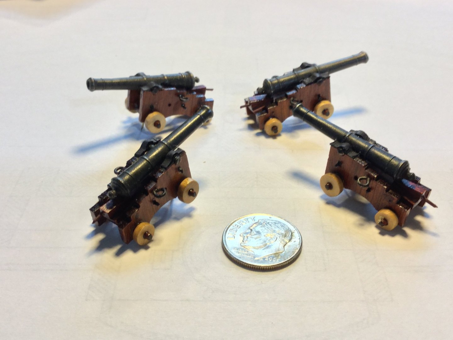
I finished up the cannons. The carriages are bloodwood with boxwood trucks. The cap squares are cardstock blacked with a Sharpie and CA'd in place. These guns are 3 pounders. At this small size, and given the model is being presented Admiralty style, I won't rig them. After fixing them in place, all that's left is to install the anchors and finish up the swivel guns.
-
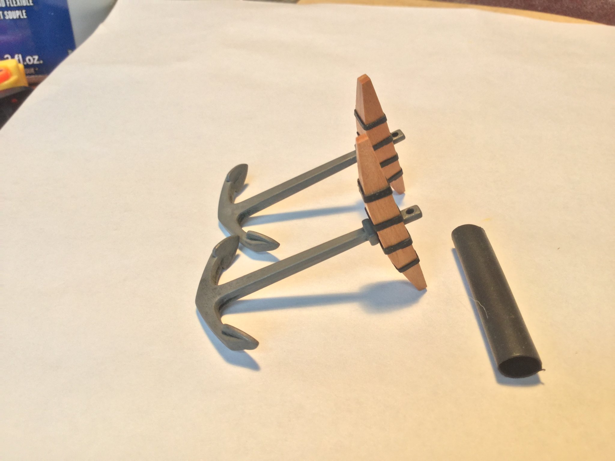
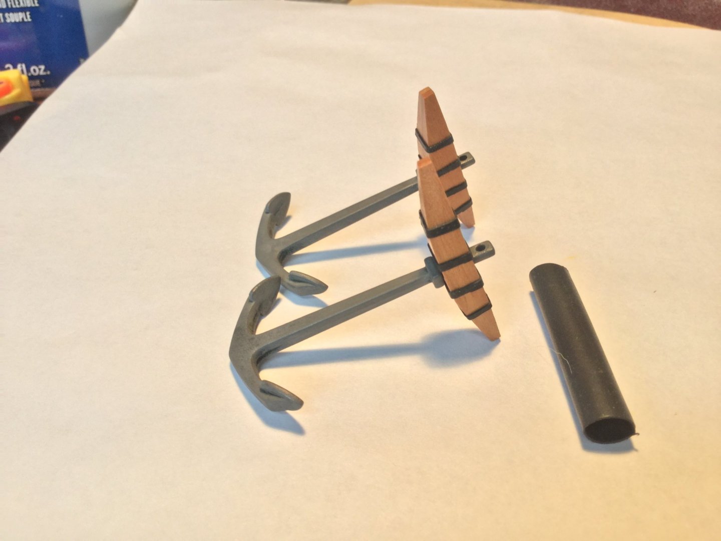
Thanks, Ken! You can get it at a hardware or big box store. Here's a link that will give you the option of 8 different diameters and more than enough for several lifetimes!: https://www.amazon.com/gp/product/B07QM8249H/ref=ppx_yo_dt_b_asin_title_o03_s00?ie=UTF8&psc=1 To use, choose an appropriate diameter tube and slice off the bands with a sharp X-Acto knife. Slip them on the stock in proper position and put the stock in a preheated 300 degree oven for 5-10 minutes. Done!
-
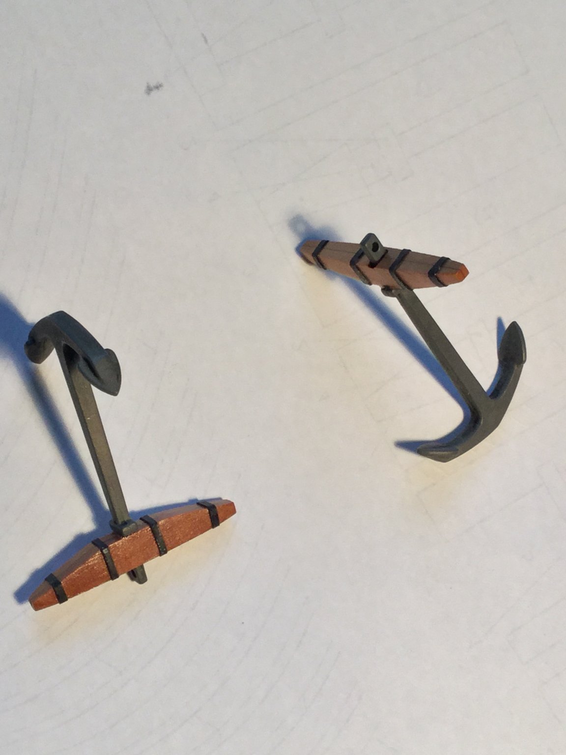
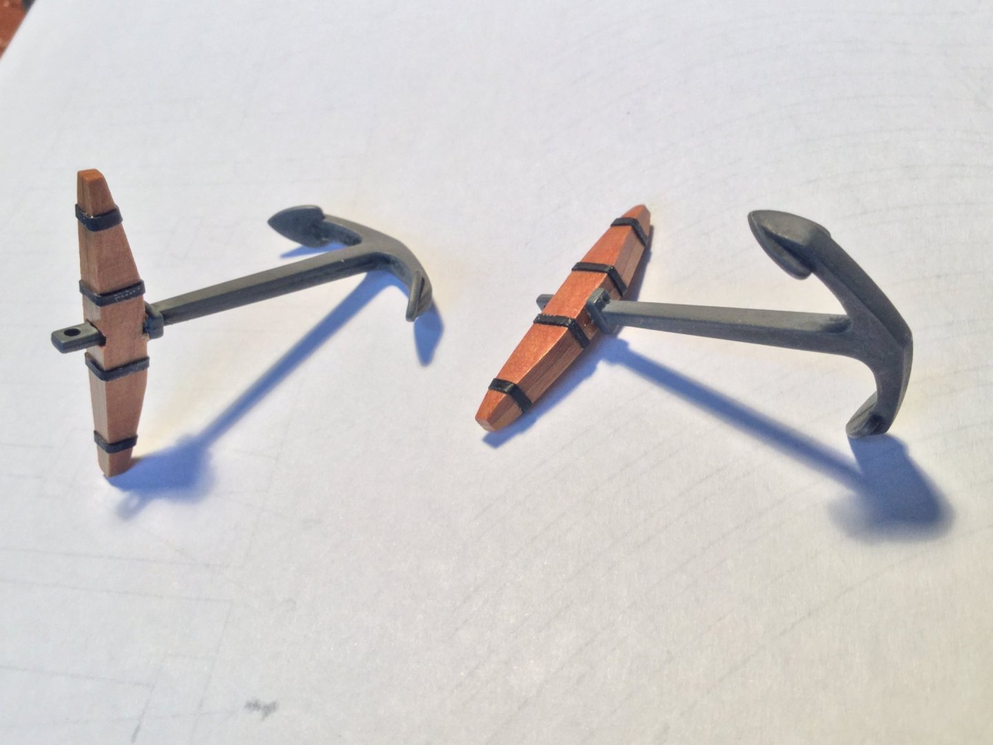
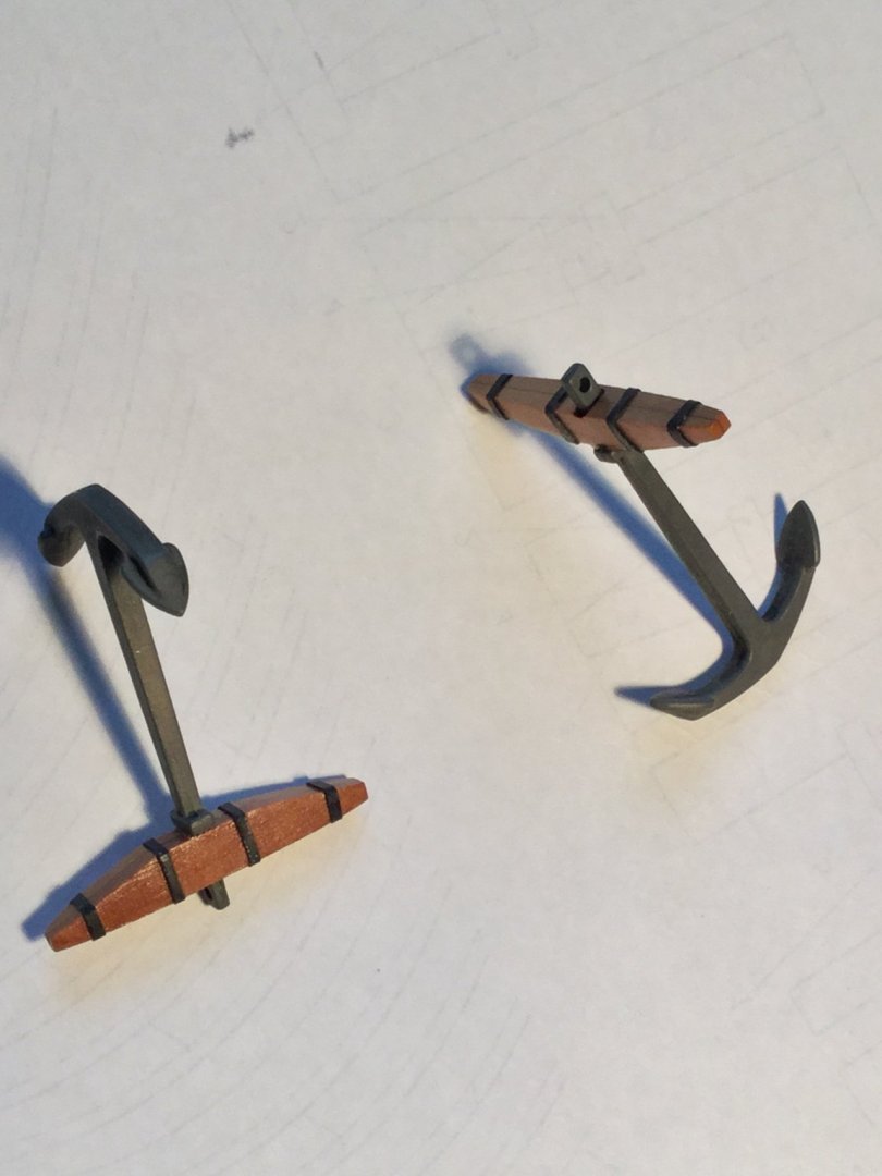
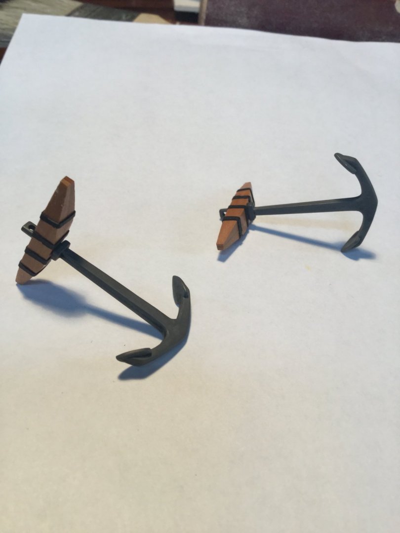
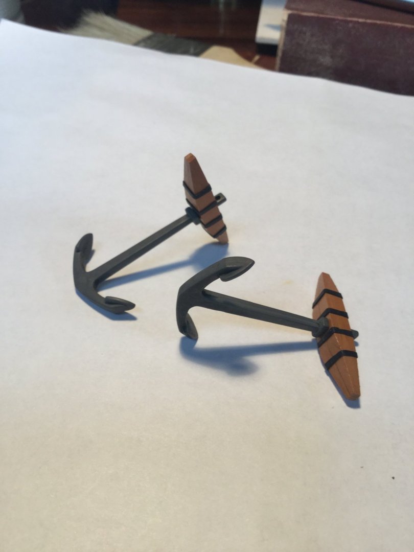
Even though I used the kit parts as templates for my remade anchor stocks (using swiss pear), I really didn't like how they turned out. The stocks are too clunky and I didn't like the reinforcing band placement. So I made them over. Much better, I think!
-
I finished up the anchors. The stocks are swiss pear, shaped and tapered. The anchor's themselves were supplied with the kit, and I wasn't to sure about the U-shape. Royal Navy anchors were more "V" shaped in the latter 18th century. The shape was more typical of Continental anchors, so would have been in use on a schooner like this I went with the kit anchors. The simulated metal bands on the stocks are thin slices of shrink-wrap electrical insulation. Cut to size, slip in place and heat in a 300 degree oven for 5 minutes. Done!
-
Hey Brian! I stole the trick about the gun handle's from you! Remember?
-
Time to get to work on the swivel guns. I can't remember where I picked up the guns that I used. The scale of this model is weird so there are no commercial swivels. I had to make my own. The barrels for the 2 pounder swivels measured about 32 scale inches long. Slightly short, but passable. My first step was to silver solder some brass rod to each gun as a handle. I the made the gun brackets from sheet brass and brass rod, and drilled holes for the trunions. Lastly, afrer blackening all the parts, I made the little balls on the ends of the handle. I build up several layers of thin CA glue until I got the size I wanted, then painted them red. Next is assembling the guns and mounting them.