allanyed
-
Posts
8,047 -
Joined
-
Last visited
Content Type
Profiles
Forums
Gallery
Events
Everything posted by allanyed
-
 B.E. On the plus side, with the keelson and footwaling strakes and a full compliment of frames, much of the inside of the planking will be unseen. The planking brings up a question for which I hope you or one of your build followers can answer. Lavery makes the following comment on page 223 of The Arming and Fitting of English Ships of War: Like the yawls, it <cutters> originated at Deal, and was originally clinker built. Unlike the yawl, the cutter remained clinker built; only cutters issued for foreign service were normally carvel built. My question is, what does foreign service mean in this case? Was this for cutters on ships that sailed to foreign ports, cutters that were on harbor duty in a foreign port, or something else? Regardless, got to love the boat build and your photos and explanations. Thanks again for sharing with us. Allan
- 614 replies
-
- 2
-

-
- Indefatigable
- Vanguard Models
- (and 1 more)
-
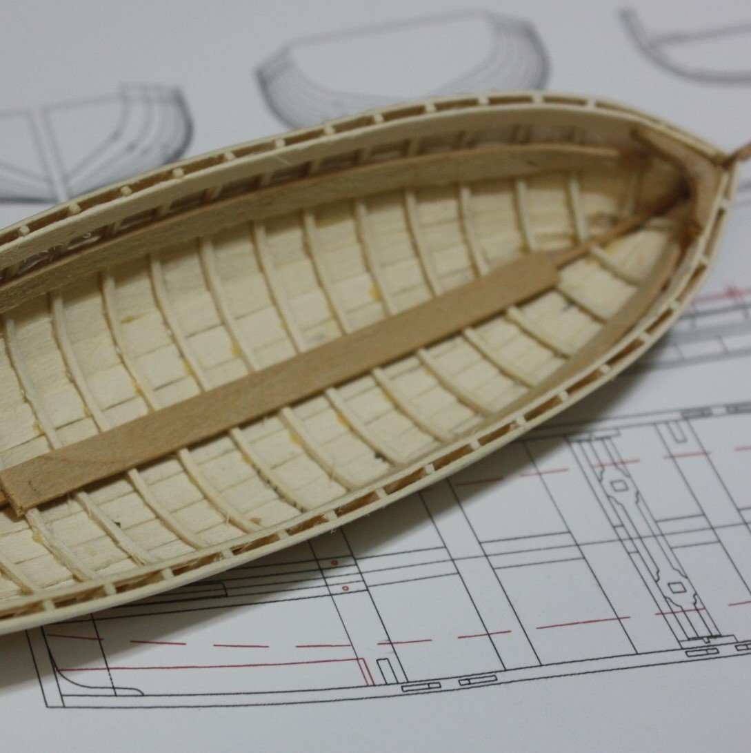
I agree that holly is indeed limited as to where it can be used effectively, but one of the things I love to make from holly are frames for ships boats and sometimes the planking as well. If soaked for a few minutes in water, they bend like paper and hold their shape once dry. Allan

-
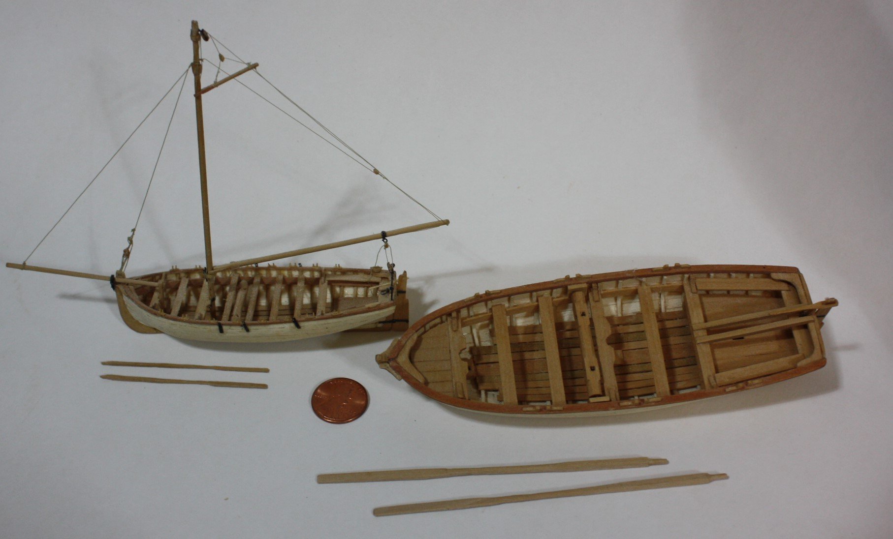
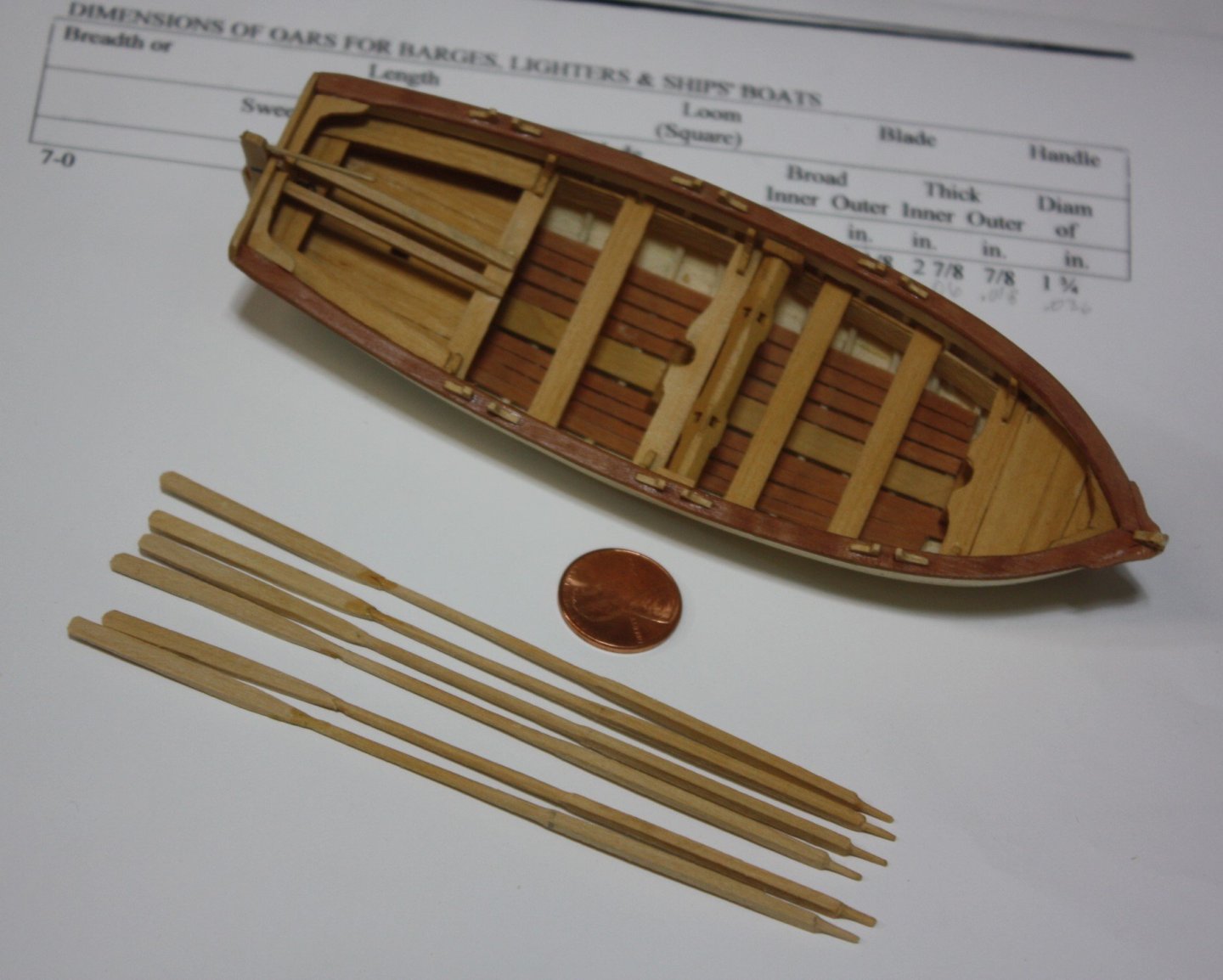
As Keith mentioned, it is sometimes better to make the oars in two pieces. The first photo below has oars in two pieces (scale1:48) The oars in the second photo are all single piece both for the 23 foot launch in 1:48 and 32 foot launch in 1:96. Hand tools were used for making the oars from scrap strips, so high tech equipment is not required. Allan

-
Just tuned in to your build and am duly impressed with the high quality of your work! I may have missed the referenced Excel spreadsheet. Is there a reference to where this can be found in posts by you, Dr. PR or elsewhere? Many thanks George Allan
-
Kudos to you for the very very nice work on the sails! I am not a fan of cloth sails as they will never be to scale at our most common scales but your sails are far and away the best ones I have seen in a long long time. Do you think a very high TC cloth (600 or more) would work as well as what you used, using your sewing methods? Again, great work! Allan
-
Just tuned in and I am very happy that I did. Love that it is a POF build and your workmanship. Allan
-
Endeavour by Bill97 - OcCre - 1/54
allanyed replied to Bill97's topic in - Kit build logs for subjects built from 1751 - 1800
You might want to study planking tutorials in the MSW data base as well as the four part video series by Chuck Passaro before tackling the second layer. Learning good planking techniques can be a big help on future projects. Allan -
Hi John, A warm welcome to MSW to you. There are alternate routes to get to your destination. Study the build logs, both kit and scratch to get an idea of what is available and what might meet your needs and desires. One of the best series, if not THE best for a beginner is the three boat series designed by member David Antscherl. https://modelexpo-online.com/Model-Shipways-Shipwright-3-Kit-Combo-Series-with-Tools-Glue-and-Paint_p_5290.html Good luck! Allan
-
Hi Gregory These drawings from Caruana were meant as the rigging for stowed gun rigging options, not how the breech line was secured to the rings. The types of securing of the breech rope were as described in post #2. My apologies for any confusion. Allan
-
I love bamboo for treenails, but would go with another species for oars. Even then, a draw plate does not work for me for oars as they are shaped as in the pics below from Steel which I hope you find helpful. I realize the shapes were likely different from boatyard to boatyard and era to era, but I cannot find any contemporary information prior to Steel's information. Allan Oar Scantlings and oar making.doc
-
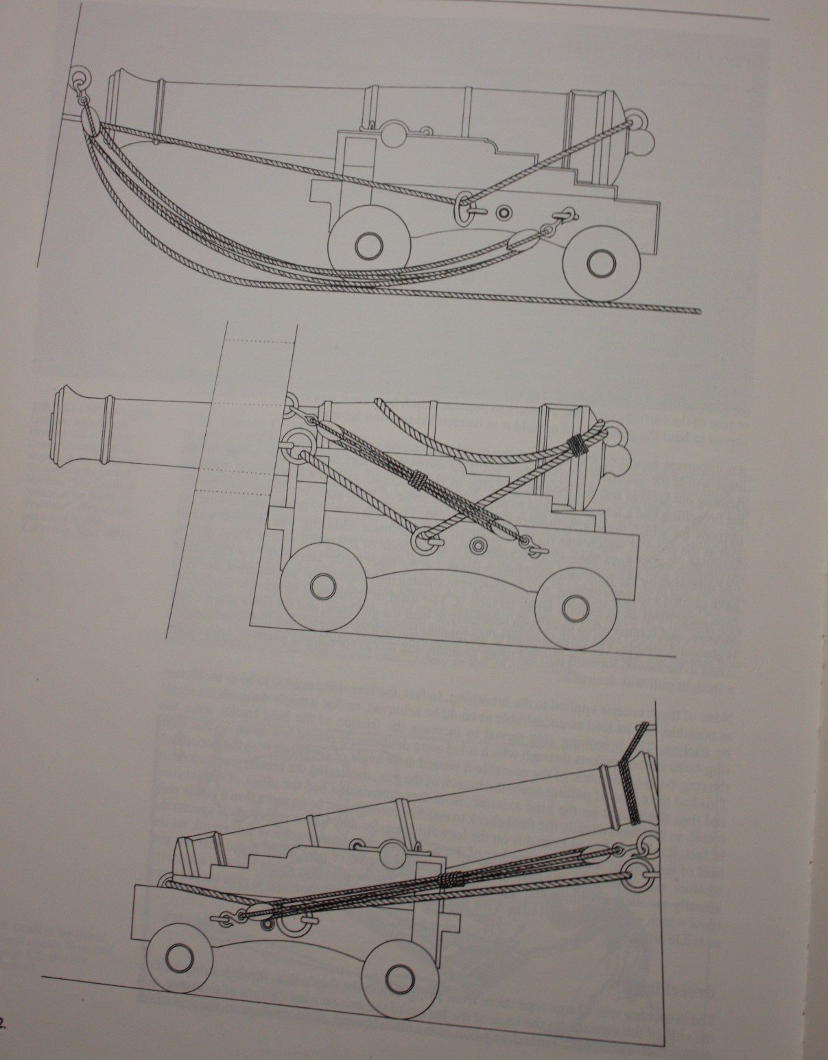
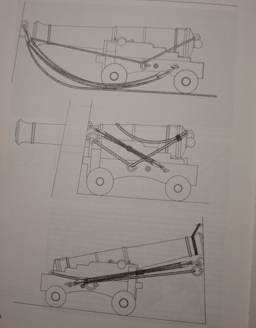
Lots of options including the three below. From The History of British Sea Ordnance Volume 2, page 382. He gives the following description of each. Illustrations of breechings and gun-tackles on a 1795 pattern carriage, redrawn from Congreve's Treatise on the Mounting of sea Service Ordnance. Top: gun tun in. Center: gun run out and secured. Bottom: gun run in, secured, and housed. Allan
-
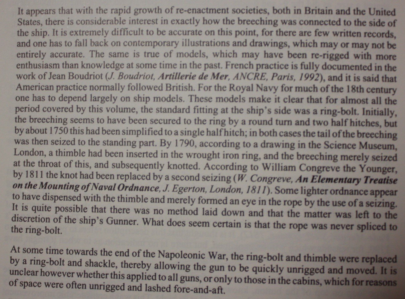
Caruana gives the following description on page 384 of The History of English Sea Ordnance Volume 2. Allan
-
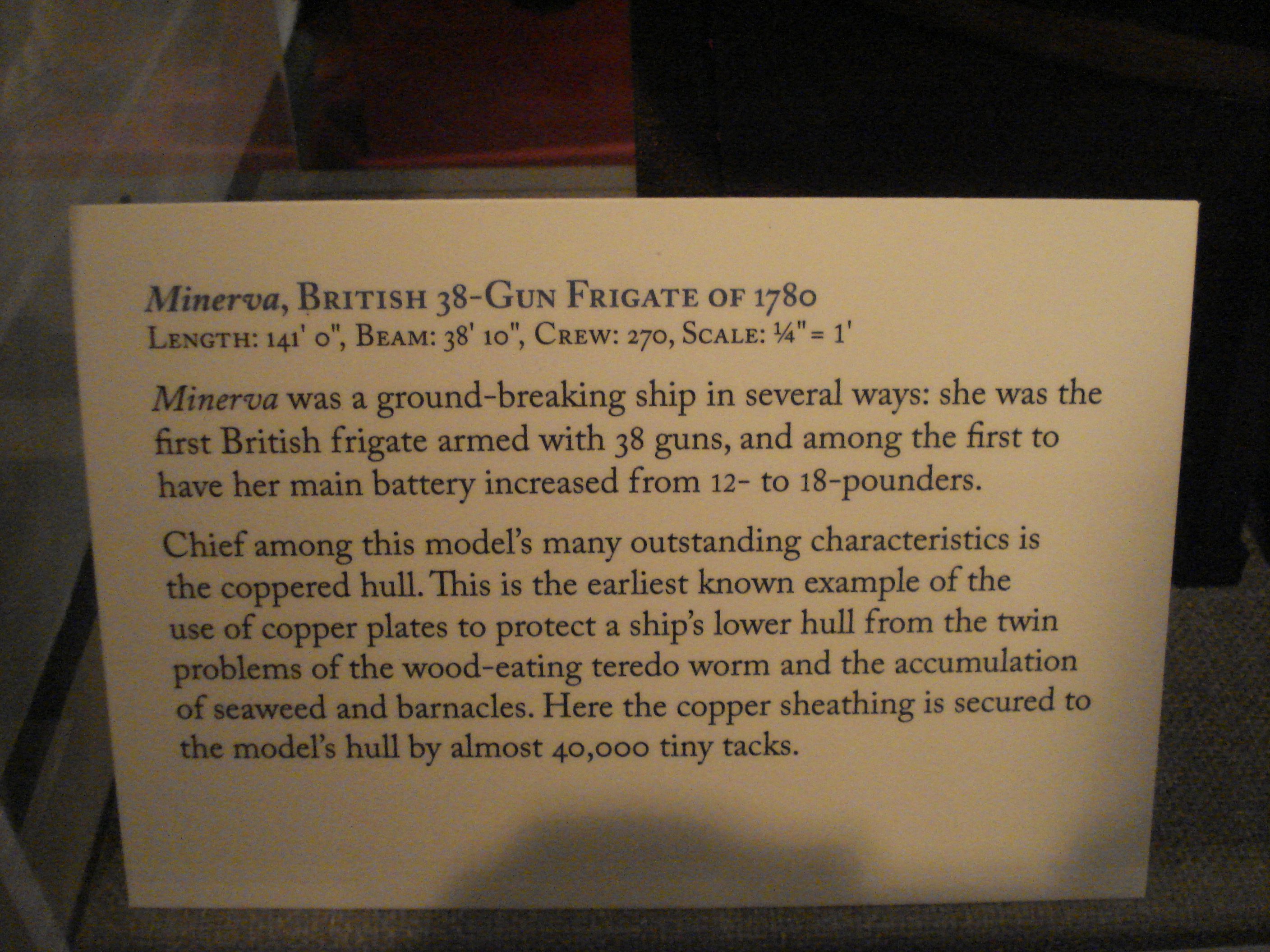
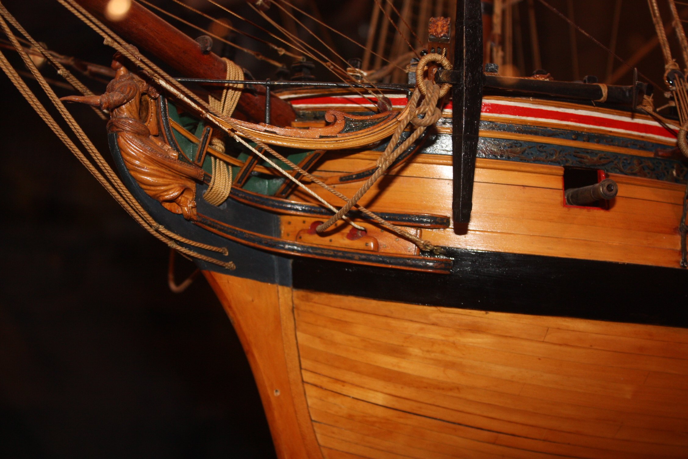
HI David I have 17 photos that I took of the model of Minerva (38) 1780 at Preble Hall in Annapolis and would be happy to send them your way if you wish. The description card they had for her in 2011 follows as well as a closeup of her planking at the bow. Allan


-
Laser cannon bracket
allanyed replied to mediocremodeler's topic in CAD and 3D Modelling/Drafting Plans with Software
Hi MM These are nice photos and credit to you for sharing but how is this related to laser cut cannon carriage brackets? I think more folks will see this and benefit from your nice work if you start another topic on topmast mastheads or include in a build log. Allan -
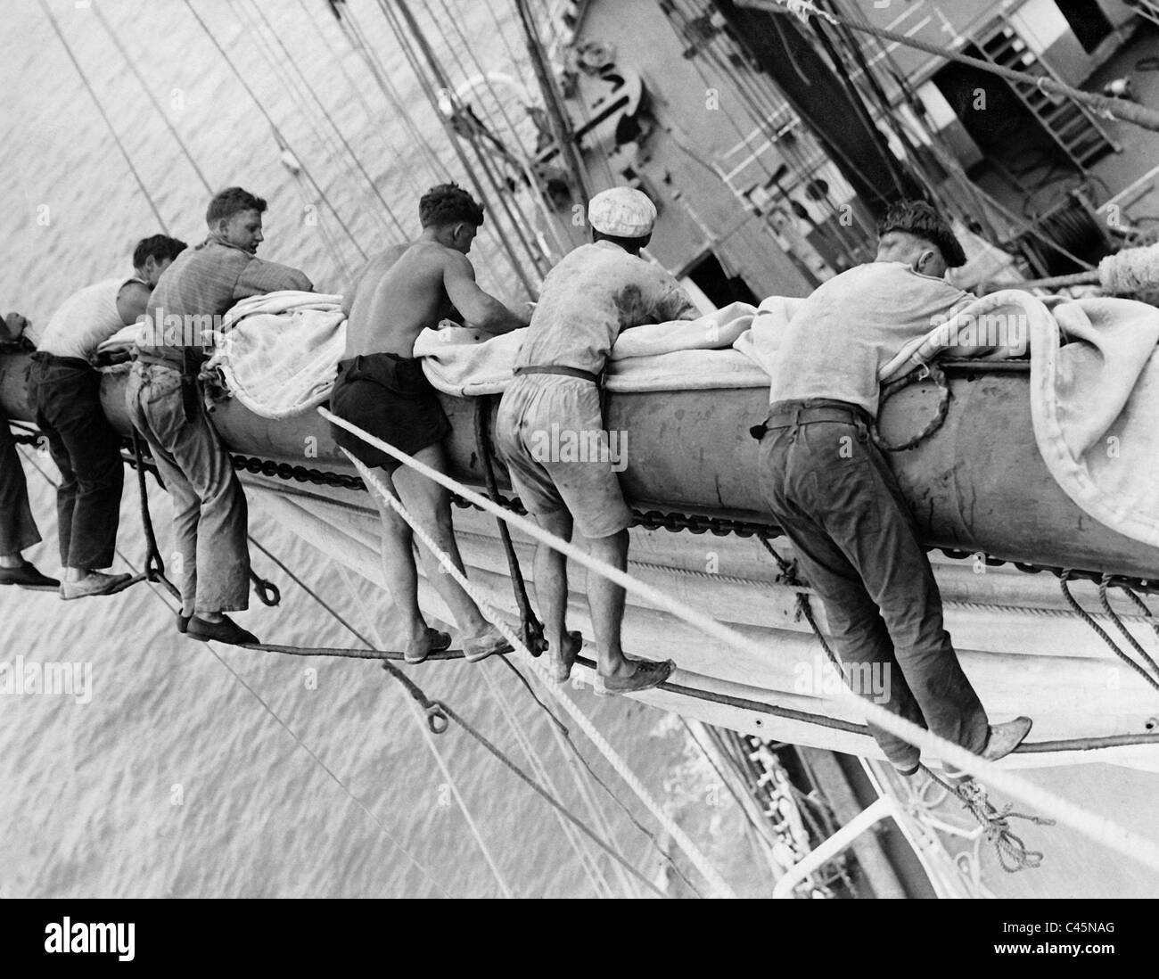
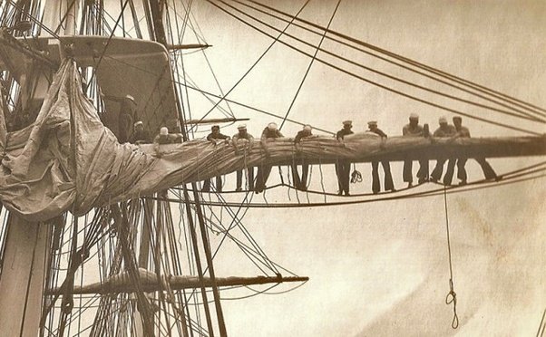
Very interesting point and your test group is a great idea. To add to any confusion that there may be James Lees mentions that the footropes or horses were 2 feet under the yard on page 69 of The Masting and Rigging of English Ships of War, but then on page 70 goes on to say that the stirrups should allow the footropes to hang 3 feet below the yard. Looking at the photos below, this makes some sort of sense. Where as the stirrups were probably pretty much the same on a given ship, not all seamen were the same height so maybe topmen assignments were partially based on their height just as strength was a consideration in assignments. The below are photos thus obviously more modern times, but may fit the discussion. Hopefully the sailors between the stirrups were the taller ones. 😀 Allan

-
Overall really nice model and your metal work is some of the best we have seen. For the future, in the past couple years, thanks to builder/author Ed Tosti, for some parts I have found copper to be better suited than brass. It solders very nicely and can be blackened instantaneously after being fixed in place on the model with diluted liver of sulfur then rinsed without staining the wood. Allan
-
Post #31 from Ross is spot on. If you take his advice you will be happy with the result. The main thing is to be sure you do not get the lifting from excessive edge bending so there is not excessive sanding needed. Allan
-
This is really interesting and great that you included it as it is not often seen. Lavery discusses it briefly in the Arming and Fitting of English Ships of War on page 143. He states that by an order of 1779 additional eyebolts were to be fitted between the ports to give extra leverage to the side tackles, when the gun was being trained. It is not clear to what extent this order applied, or how long it lasted. Allan
-
Laser cannon bracket
allanyed replied to mediocremodeler's topic in CAD and 3D Modelling/Drafting Plans with Software
Sorry to ask, and I really am not trying to be obtuse, but what is this shaft? Your topic is laser cut cannon brackets so I'm totally confused.😕 Thanks😀 Allan -
Mast hoops- general rule of thumb?
allanyed replied to skipper1947's topic in Masting, rigging and sails
Bonjour Alain WELCOME TO MSW!!! It would be nice if you posted a little intro in the new member forum here at MSW. I don't think you are supposed to post your email address. I am sure a moderator will remove it as you may get spammed if it is left there. If it is in your profile, members can find it or PM you. Regarding your question, what era, what type of vessel, which mast, what nationality? Are you talking about the hoops on the top and bottom of the wooldings or the hoops to which sails are attached on a schooner for example? Again, welcome to MSW Allan -
Hamilton, Kudos for going the extra mile/km. Tennfox, many are happy with what the kit provides, which is great, but some are interested in going a bit more in depth. The dimensions of virtually every piece of your ship is in the 1719 Establishment. Many of these are inconsequential when viewing the finished model, but some are quite noticeable. These can be found at RMG and in several books if you are interested in this kind of information for now and in the future. Allan
-
Setting up deadeyes to shrouds
allanyed replied to Lost and Confused's topic in Masting, rigging and sails
I will definitely try this Druxey. Am I correct to assume you do something similar with a swifter as you do for a paired shroud. With the pairs, reinstalling evenly seems like it would be pretty easy, but for a swifter is the loop at the mast head done first so it can be removed like the pairs? Or, do you find it easier to just secure it at the mast head after the deadeye is seized so it is line with the other deadeyes? (I am on the road so could not check if this addressed in TFFM IV.😀) Allan -
BE The Construction and Fitting of English Ships of War, pages 108-110 go into this is some detail. There were either two or four transom knees depending on the size of the ship. (He also mentions there were exceptions with some ships having an odd number of knees based on contemporary models.) In short the transom knees (standards) were to add strength to the transom as well as give support to the tabernacle for the flag staff as you show on your model. The fore and aft arm was sufficient to span 3 deck beams and the vertical arms terminated just below the taffrail. Allan
- 614 replies
-
- 3
-
-
- Indefatigable
- Vanguard Models
- (and 1 more)
-
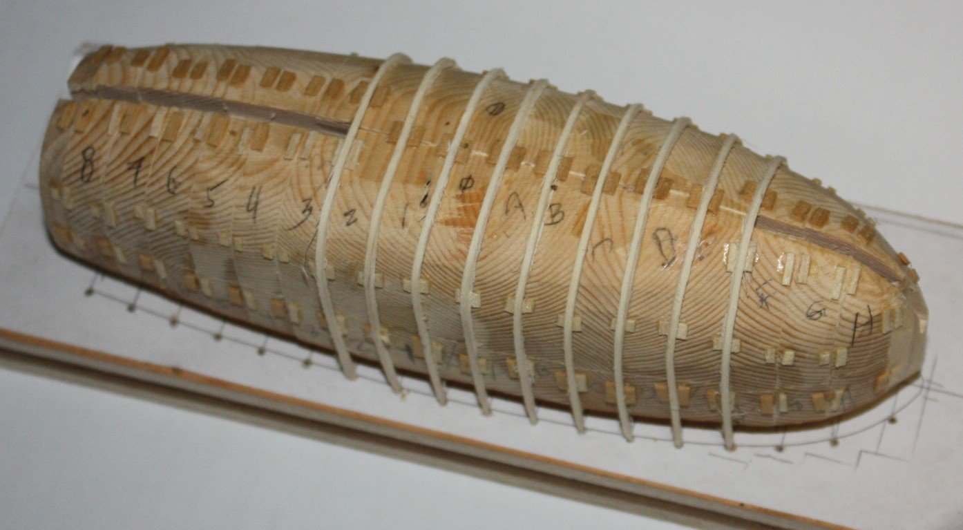
Found this on line. Creating an Original Plug When beginning the process of creating an original plug, you must first determine the type of material that will be used. Plugs can be created from a variety of materials, as long as they are dimensionally stable. These materials commonly include wood, MDF, clay, SMC, foam and balsa. If the plug is to be made from a porous material such as wood or foam, the surface must be sealed with a resin or primer. #1041 Duratec Gray Surfacing Primer is ideal for this application and will be discussed later in this article. Plugs need to have a slight taper so that the mold can be easily removed. Typically, a larger plug will require more rigid and reinforced materials. From https://www.fibreglast.com/product/Plug-Construction-Guide
-
Laser cannon bracket
allanyed replied to mediocremodeler's topic in CAD and 3D Modelling/Drafting Plans with Software
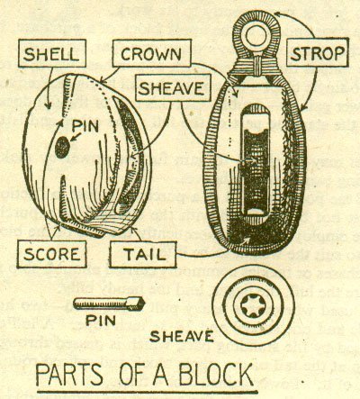
Nice work, it looks close to the below, a common single block. How did you round the edges? A block/rock tumbler is a huge time saver and does a great job if you are doing this by hand. Allan