allanyed
-
Posts
8,056 -
Joined
-
Last visited
10 Followers


About allanyed

- Birthday 04/25/1947
Recent Profile Visitors
11,359 profile views


-
 brunnels reacted to a post in a topic:
Need help sanding Vanguard laser cut oars
brunnels reacted to a post in a topic:
Need help sanding Vanguard laser cut oars
-
allanyed reacted to a post in a topic:
HMS RESOLUTION 1667 by KarenM
-
Scottish Guy reacted to a post in a topic:
Need help sanding Vanguard laser cut oars
-
allanyed reacted to a post in a topic:
Reef line length...
-
Keith Black reacted to a post in a topic:
Need help sanding Vanguard laser cut oars
-
 Have you or any other member tried scraping rather than sanding these oars? Similar to scraping a planked hull or deck, a stiff back razor blade or scalpel blade can be controlled more easily at times and might give you better results. Allan
 -
allanyed reacted to a post in a topic:
Need help sanding Vanguard laser cut oars
-
allanyed reacted to a post in a topic:
Reef line length...
-
allanyed reacted to a post in a topic:
HMS Diana 1794 by newbee - Caldercraft - 1/64
-
allanyed reacted to a post in a topic:
HMS Diana 1794 by newbee - Caldercraft - 1/64
-
mtaylor reacted to a post in a topic:
Bending hard brass.
-
mtaylor reacted to a post in a topic:
Hello from Cleveland (or thereabouts)
-
Scottish Guy reacted to a post in a topic:
Bending hard brass.
-
Scottish Guy reacted to a post in a topic:
Bending hard brass.
-
dunnock reacted to a post in a topic:
HMS Diana 1794 by newbee - Caldercraft - 1/64
-
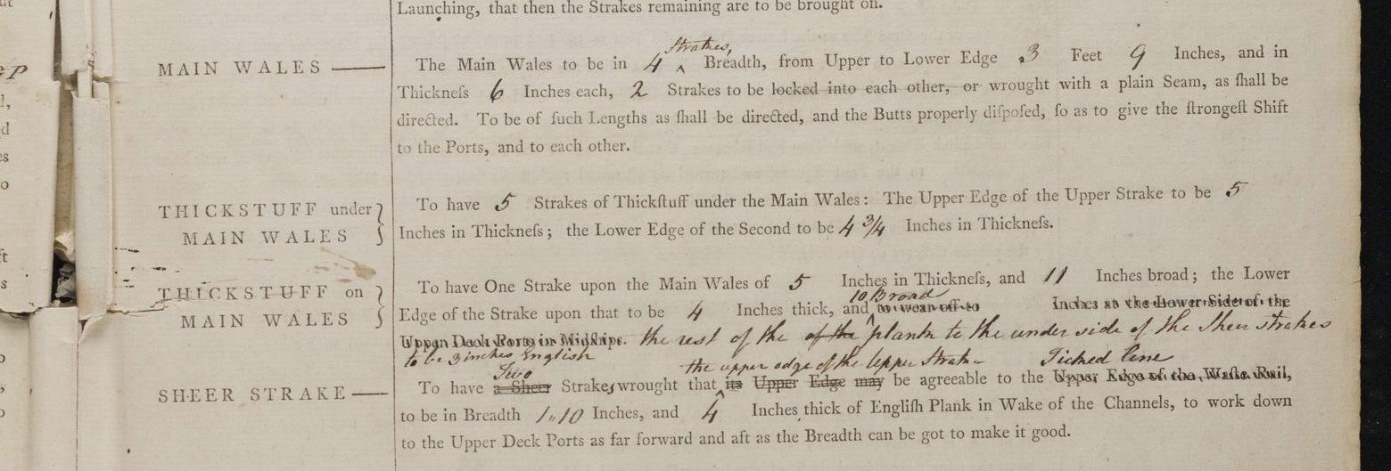
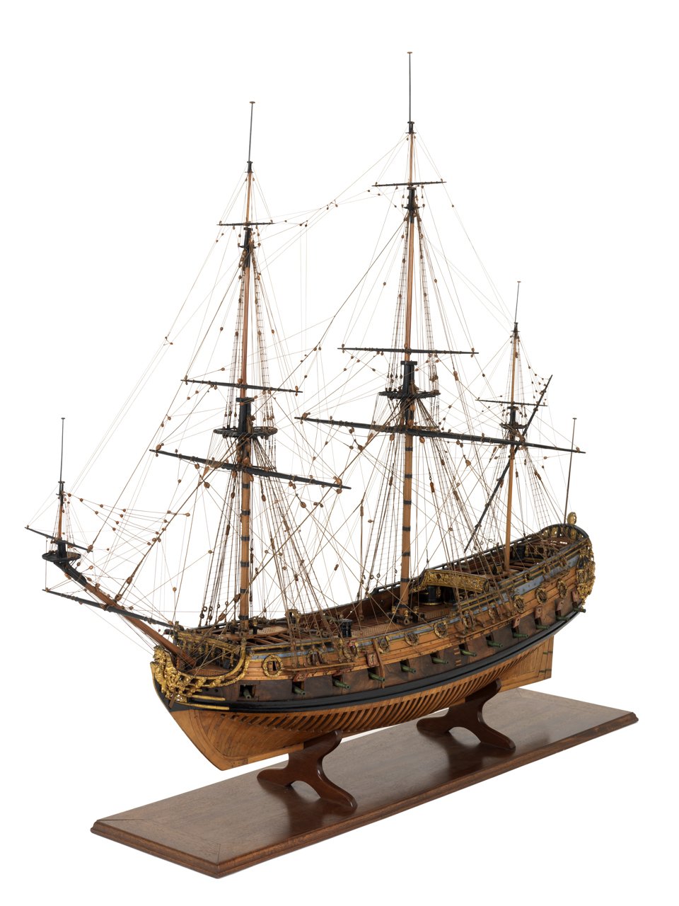
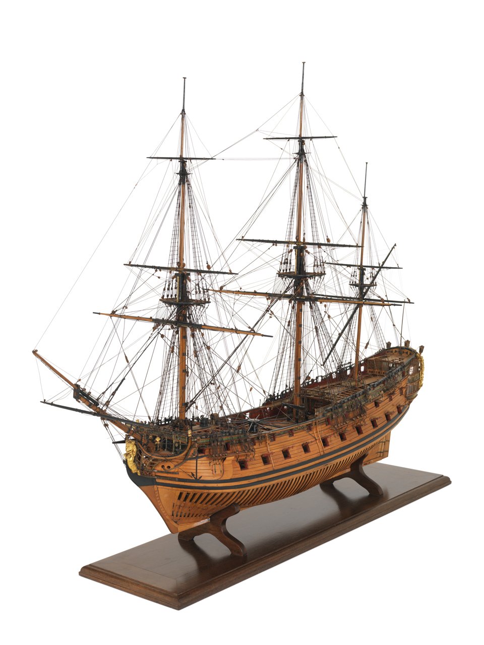
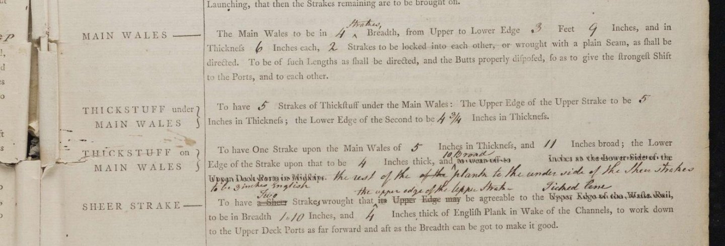
David Your perseverance is commendable! It may be the photo but if the two thick tape lines are the top and bottom of the wales and black strake above the wales it looks to be very close to where it shows on the contemporary drawings forward. At the stern it appears to be a bit high but again, it may be the photo. The line of the wales can be seen clearly on the high res drawings on the Wiki Commons site (https://commons.wikimedia.org/wiki/Category:Ship_plans_of_the_Royal_Museums_Greenwich pages 4 and 5) as well as on the photos of the model at RMG Collections of the Apollo/Artois class of which Diana is a part. https://www.rmg.co.uk/collections/objects/rmgc-object-66303 There are low res drawings on this site but the high resolution version on Wiki Commons are often more helpful. The bottom of the wales aft is about 77 inches below the bottom of the aft most gun port opening. The bottom of the wales is 84 inches below the bottom of the forward most gun port opening. For the wales and strake on the wales, the dimensions from the contract are below. I may be mistaken on this particular ship, but often the first strake of thick stuff (in this case, one strake) above the wales is black as well as the wales. Allan
-
allanyed reacted to a post in a topic:
Lathe Question
-
allanyed reacted to a post in a topic:
Another OcCre "Save The Date" Release - April 28, 2024
-
Canute reacted to a post in a topic:
Bending hard brass.
-
Keith Black reacted to a post in a topic:
Hello from Cleveland (or thereabouts)
-
allanyed reacted to a post in a topic:
Bluenose II by gmctaggart - Billing Boats - 1:100
-
Welcome to MSW Eric. Loved your intro! If your models are as well done as your introduction, you will have great success. Regarding your first build choice
-
Bending hard brass.
allanyed replied to navarcus's topic in Metal Work, Soldering and Metal Fittings
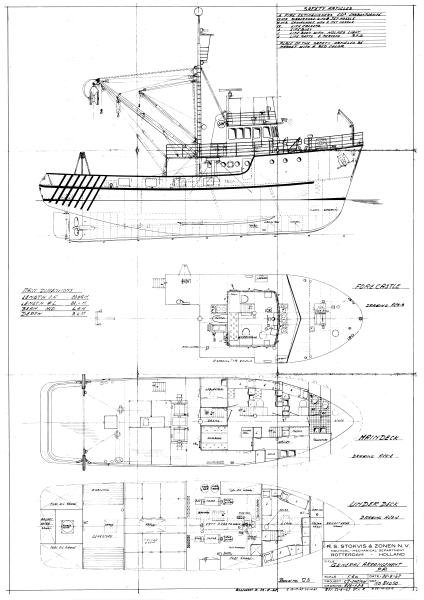
Angel, It looks like your prop is in the wrong place or the diameter is too large. Is it possible to relocate the propellor shaft or go with a smaller diameter prop? Also, you can add a piece similar to the sketch below although it is probably not a good solution. If the ship had a wooden keel then this would work well and could also take a false keel across the entire length of the ship as well. Can you tell us which vessel this is? Thanks Allan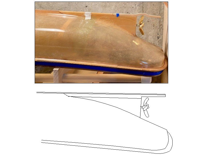
-
Similarly you can draw a box that is any given dimension in both the x and y axis such as 4 or 5 inches (100 or 150mm) somewhere on the drawing that you want to have printed. Once the drawing is printed, check the length and height of the scale box with a vernier caliper to confirm the printed plan is accurate. For larger drawings I like to use architectural engineering printer shops and ask them to check the scale box on the printed sheet. They have rarely had to make minor adjustments. I have also gone to Fedex offices that have large format printers. More often than not they have had to make small adjustments to get accurate results which they were happy to do. For those that do not do their own drawings but get prints from RMG and other sources, the copies are suspect as the original plans are often distorted to some degree which is not surprising after a few hundred years. Allan
-
Bending hard brass.
allanyed replied to navarcus's topic in Metal Work, Soldering and Metal Fittings
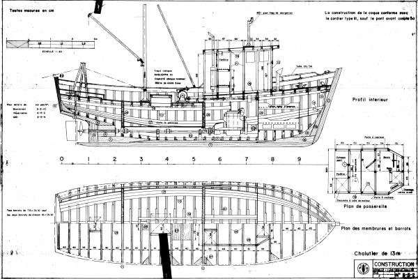
Looking at drawings of various trawlers and boats I still cannot figure out what Navcus is looking for. Attached show skegs that are below the prop so I assume (usually a bad idea) it is this area. If the skeg has to be bent to clear the prop it seems like the prop reaches below the keel which is odd for these boats. Hope he or she posts a drawing as now I am curious.🤔 Allan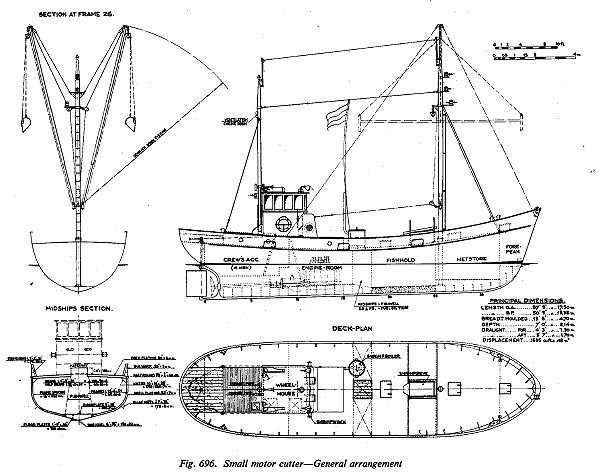
-
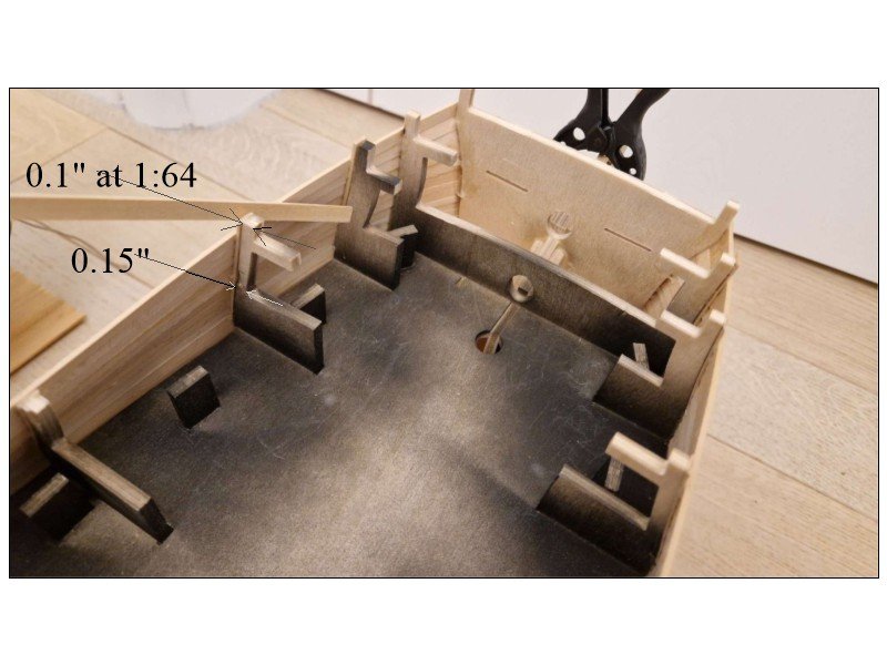
This might help. From the Shipbuilder's Repository 1788 which should be close for Agamemnon 1781: Fourth futtocks moulded at the upper deck 9 3/4" Top timbers <at the top end> moulded in the range of the forecastle 5 1/4" The dimensions below are what they would be if made to scale 1:64 This would apply to the forward frames as well. It looks like the forward most frames moulded dimension is too heavy. Perhaps the kit has it extra thick due to the pressure of the planking bend in that area. Allan
-
Richard, If you are relegated to using brass, cleaning the assembled pieces with a solution of pickling acid is by far the best method in my experience. If there are blobs of solder I will file off any excess first then soak in the acid batch. Sparex #2 is one brand that works well and can be found on line. Vinegar works but not nearly as well as the Sparex in my experience. Once pickled rinse in water and dry then blacken. I find copper easier than brass in many situations. It is easy to solder the pieces together, then clean with a file and/or steel wool followed by Sparex or try acetone. They can then be fixed in place and then blackened with diluted liver of sulfur in situ with a small brush. Rinse with a clean brush with water. The diluted LoS will not stain the surrounding wood. Allan
- 28 replies
-
- 2
-
-
- Victory
- Artesania Latina
- (and 1 more)
-
Doug, Welcome to the best ship model website in existence. Allan
-
Welcome to MSW Mberg Allan
-
Tiziano You are most welcome and thank you again for allowing all of us to travel along with you on your journey. I am emailing you an idea you might like. Allan
-
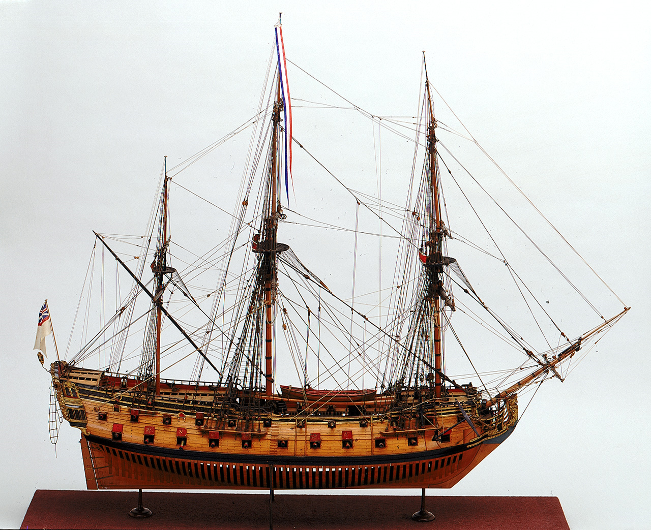
Welcome to MSW John! Not to worry about the sails, you are not alone. While there are contemporary models rigged with sails, there are also many hundreds, including those at the Royal Museum Greenwich and Preble Hall in Annapolis, that are fully rigged sans sails. Three examples from the RMG Collections website of models built in 1695, circa 1714, and 1720 follow. Allan


-
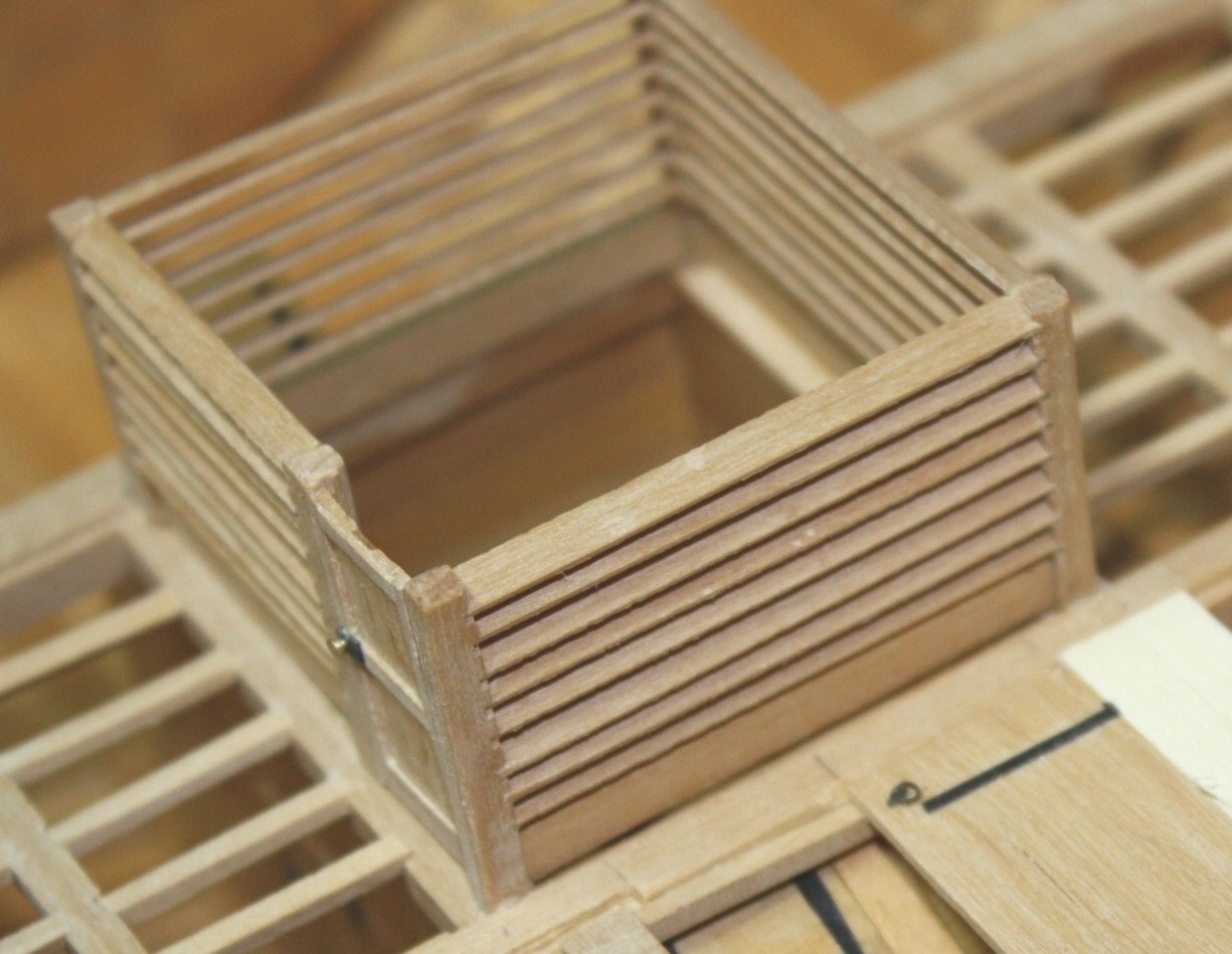
I realize the kit has the supplied parts, but the future and FWIW, the bulkheads over the well on the orlop were typically louvered or partially louvered in the upper portion rather than having completely solid bulkheads. I could not find any reference that the upper well area was made entirely with solid bulkheads on Victory but she (and other ships) may be an exception. Allan
- 28 replies
-
- 2
-
-
- Victory
- Artesania Latina
- (and 1 more)
-
Hi Gregory Yes I am, but as with so many things very few are cast in stone on these ships of old. This is the first document I have seen that specifies other than singles on smaller than 32 pounders so heretofore I had relied on Caruana. The dates are very late in the 18th century so I wonder if this was a time of change for the types of blocks. So many choices. If Caruana missed this one too at least I am in good company. Appreciate your point. 😀 Allan
-
Welcome to MSW Jay. What is your area of interest, kit, scratch, era, etc? Allan