


wefalck
-
Posts
5,537 -
Joined
-
Last visited
Content Type
Profiles
Forums
Gallery
Events
Everything posted by wefalck
-
 Thanks for your kind word about by engineering and photographic endeavours! I haven't gone back to Speakers' Corner in decades, but have the feeling that it is not as original as it was (or appeared to me/us) back in those days. I was there as a teenager and wish I had then the photographic experience and equipment I have now. A lot of picturesque aspects of London, such as the markets (Billingsgate, Covent Garden, Smithfield, etc.) have disappeared. I wish I had taken more pictures then (but film was expensive). Back in the 1970s and 1980s London's Clerkenwell Rd. (east of Farringdon) still was a paradise for precision engineering supply needs. I remember visiting the last watchmaking suppliers in around 1989 (Shorts Bros.), shortly before they threw the towel. And there were lots of model shops all over town, plus Model Boats down in Greenwich ...
 -
The CHARLES W. MORGAN should have had such structure, so perhaps contacting Mystic Seaport might help? On the other hand, the stoves/baking oven on ordinary warships must have been very busy at times and I don't recall having seen such structure under their bottoms in contemporary drawings. There would be some sort of iron drip-tray around them to prevent the surrounding deck from becoming soiled.
-
I prefer ball-cranks over handwheels, but didn't actually make any myself, because I found a source for small ones. However, I made quite a few ball-handles. Here is my procedure for them (you have to scroll about half-way down the page): https://www.maritima-et-mechanika.org/tools/micromill/micromill.html. I should add, that I made myself a ball-turning attachment about 15 years ago, which greatly facilitates such operations. The worst are those turning sleeves on the handles of crank-wheels, no feel for fine machining ...
-
Indeed, that's what I meant. It is normal, that the distance between the davits is smaller than the length of the boats, because such heavy boats have to be suspended from their backbone, the keel, rather than the stem- and stern-posts. This procedure of swinging the boats first backward and then outward was standard procedure, described in instruction manuals of the time.
-
Nice machining, as always 👍🏻 Again, I am surprised that Stuart make you turn the handwheels from stock, rather than supplying cast pieces - perhaps a question of cost. Personally, I am a great fan of ball-handles and similar - not only for aesthetic reasons, but also for reasons of comfortable handling. For my watchmakers lathe-project I made quite quite a few of them myself.
-
Cover or not cover certainly depends on the kind of weather/climate encountered. As noted above, you want to keep the wood humid in order keep the boats serviceable at any moment. On the other hand excessive water in the boats (although there would be a draining plug in the bottom - cf. the well-know sea shanty) could lead to rot, particularly in a freshwater environment. Conversely, a hot and dry semi-tropical climate would lead to bleaching and cracking of the wood and any paint on it. So in more extreme climates you may need to protect the boats. In the first pictures of USS TENNESSEE shown above, you can see the spar (minus the bolsters) I mentioned earlier. In fact, on rigged ships, these spars may have doubled as reserve-spars. If I understand the topology of USS CAIRO correctly, than the davits would need to be turned in order to swing out the boats. You probably would need stays to steady the davits, leading from a horizontal eybolt in their tops to somewhere on the ship. There may be also a stay between the the davits, which helps to steady them in the secured position and to co-ordinate their movement, when swinging out the boats. Sometimes a number of knotted ropes werer hung from them to allow the crew to descend more easily into the boats. When the tarpaulin was on, they would be coiled and tied together.
-
Sometimes davits or anchor-cranes had a ringbolt in them or they stropped a rope with an eye-splice around them into which the hook was hooked and the tackle set taught - on a well-kept ship nothing dangles or bangs. The ring reaching up through the tarpaulin was not my idea, but it was common practice as one can see on old photographs. The tarpaulin had to slots reaching half-way across the boat so that you could remove it wihout having to unhook the tackles (which would have been impossible anyway with the boat hanging on them). The slots were closed with an overlapping piece and laced up like a boot. There is also no interest in keeping the boat completely dry. To the contrary, every now and than a couple of buckets of water were spread in them to keep the wood humid, otherwise it would shrink and the seams would open, making it leaking initially while in use. The tarpaulin was just there to keep dirt and excessive salt out and the equipment in or protected.
-
I can echo this ... I don't know anything re. the practices in the USN and in particular their brown-water practices. However, in other navies, boats were often stored hanging from the davits, rather than on skids. There would be a sort of spar connecting the two davits that had a couple of soft bolsters attached around them against which the boats rested. The boats were pulled against these bolsters using flat straps (braided fancywork or canvas strips) going cross-wise from the top of the davit to the spar. The liftign tackles were hooked into chain slings that consisted of two parts: a vertical one to take the actual load and a +/- horizontal one to the stem- resp. stern-post to prevent the longitudinal swinging. There may have been some sort of long chain-link penetrating the tarpaulin covering the boat.
-
Yes, that is a nice Web-site. I knew it, because I wanted to identify a working model of a vertical mill I have and was hoping to find it there.
-
Nice machining, as always. This long hole through the cross-slide would have absolutely frightened me - it can easily deflect ... OK, this is only a model, but two things wondered me about the cross-slide, that there don't seem to be a provision for a gib-strip and that there is no spindle-nut, but the thread is cut directly into the meat of the saddle.
-
I am impressed by both, your impeccable workmanship (as usual) and your perseverance in those difficult times.
-
My small antique mill would bail out above 0.1 mm cuts … I find, if you crank slowly, you can get very good surface even on steel.
-
I am quite shocked that the saddle/apron was supplied only as a huge lump of steel and not as a proper casting. On the other hand, working from a block makes clamping and aligning easier …
-
Makes me wish to start a project for a topsail-schooner that has been in the back of my mind for years ... Interesting, that you are starting to put the sails on before the main-mast is stepped. How do you handle the running rigging that leads aft, such as the braces on the upper yards?
-
In the old days, a couple of guys were sent aloft to sort out the topsails, but modern safety-at-sea-rules may be quite restrictive in that respect. As much gear as possible has to be operated from the deck.
-
If I see correctly, the topsail is only attached to the topmast at two points, right ? This seems quite unsual and aerodynamically not very efficient, though it allows easy setting and taking in. Excellent workmanship, as usual, of course ...
-
HMCSS Victoria 1855 by Banyan - 1:72
wefalck replied to BANYAN's topic in - Build logs for subjects built 1851 - 1900
Interesting question, indeed. I had a quick look into *MIDDENDORF, F.L. (1903): Bemastung und Takelung der Schiffe.- 401 p., Kassel (reprint 1977 by Horst Hamecher). while he gives dimensioned drawings and tables for virtually everything you can think of, there is nothing on the chains themselves. At that time they must have been already standardised industrial products. However, he mentions in passing, that chains running over blocks should be short-link chains. That seems logic, because they would run smoother around the sheaves, than longer-linked ones. I think an inside length of the link of 2.5 times the wire diameter would look right for short-link chain. Anchor-chains, when running around sprockets (or any other type of chain used with sprockets) would need somewhat longer links to accomodate sufficiently sized fingers. ---------- * BTW, Middendorf designed and rigged, among others, the only five-mased ship PREUSSEN.- 973 replies
-
- 6
-

-
- screw
- gun dispatch vessel
- (and 5 more)
-
However, be aware, the copiers often distort images and that the scaling factors may not be exactly equal in x and y. It is a good idea to draw a not too short scale for both axes onto the drawing and check, while in the copying office. Also lines will be 9% wider then. A better way may be to scan or to have them scanned and print them out scanned. The advantage is also that you can print at home blow-ups of details as working drawings, e.g. for adding measures etc.
-
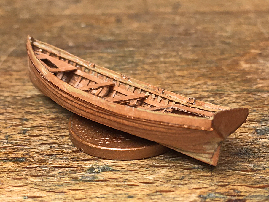
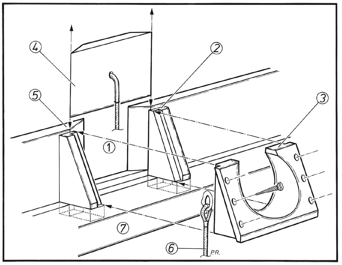
Glad to hear that I lived up to your expectations *************************************************** Jolly-Boat continued 5 A short update before painting begins. A couple of small details were still missing, including the rubbing strake, for which again 0.2 mm copper wire was used, the stanchions under the seats, and the row-locks. The stanchions were composed from three layers of laser-cut paper. Perhaps I should have milled them from brass rod, but I was somehow too lazy to take out my micro-mill. Design of the row-locks. Drawing by Peter Rückert in LOGBUCH 2-2019. The row-locks actually form the stanchions for the wash-strake, which structurally and strictly speaking is not part of the hull, but attached to it to heighten the free-board of the boat. They consist of two wooden clamps on which the actual row-lock in cast bronze sits. The wash-strake has square cut-outs for the oars, which are closed with wooden ‘shutters’ fitting into bevelled slots. To illustrate this, I enclose a drawing by a colleague and expert on the Imperial Navy boats, who sadly died last year much too young. The basic shape of these tiny specs of paper were cut out using the laser-cutting and lacquered into place. Originally, I had envisaged to fashion them from brass, but had the feeling that they were just too small to make this practical. I decided to show the locks closed, which saved me the trouble of having to cut out the square openings in the wash-strake. I just little scored them with a not too sharp scalpel. With this, the boat is ready to be painted. There is still some iron hardware that has to go on, but this will be installed after the painting, as it is supposed to be galvanized iron. I am actually not sure, whether the iron-work was painted over or left bare, but think it will add more detail to leave it bare. The first of paint on the outside is now drying … To be continued ....
- 873 replies
-
- 18
-
-

-
There are two solutions for this - use an (improvised) steady-rest as described above - the card-board will not survive more than one yard (the spar tapered on both ends), but will work. The same can be used also in the tailstock to protect machined surfaces. - turn two half yards and pin/glue them together.
-
Not exactly wheel-chair-friendly the deck ... one has to really pay attention not to trip over the lines leading to whinches and then the cleats ...
-
Well, may be you should get yourself a 2D-CAD, then up- or down-scaling is jsut a question of pushing a button ... I wouldn't put much trust in zu Mondfeld, rather check out the long list of contemporary anchor-drawings provided in the Danish archive. They begin largely from No. G 4445 and are often associated with particular ships and dated (see the one for the Jagt HELLEFLYNDEREN above).
-
Thanks, gentlemen, for your kind words! Brian, I would rather use styrene sheet, but my little cheapo laser-cutter just doesn't deliver enough energy to evaporate/burn even thin styrene - plus the high reflectance of white material. Black styrene might work, but I don't think they make it in 0.15 mm, 0.2 mm or 0.25 mm thickness. Paper has a lot less of mass per volume to burn, than plastics. Pat, I got it through ebay from China, search for 'surgical blade breaker'. I saw them decades ago in a catalogue for surgical instruments, but they were extremely expensive. I gather the Chines now sell 'seconds' through the Internet or just produce cheaper, so the stuff becomes affordable for non-professionals. However, for Europeans this source kind of dried up, since we are charged import duties now from the first cent on - and I am not happy with the geopolitical developments there.
-
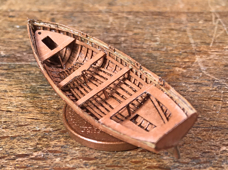
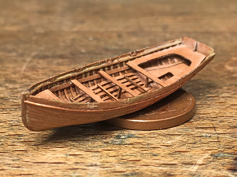
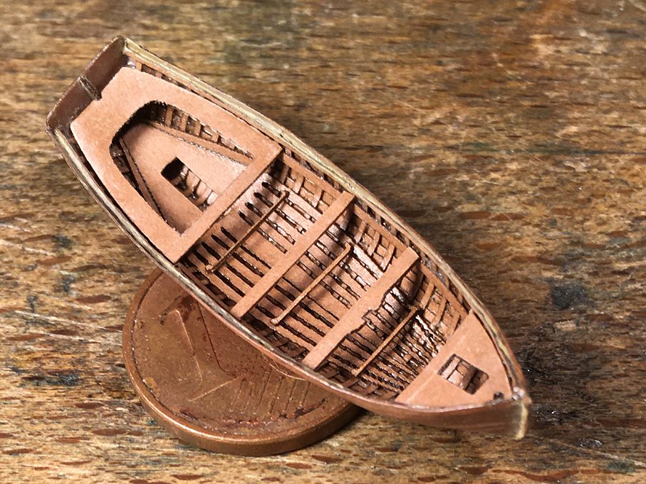
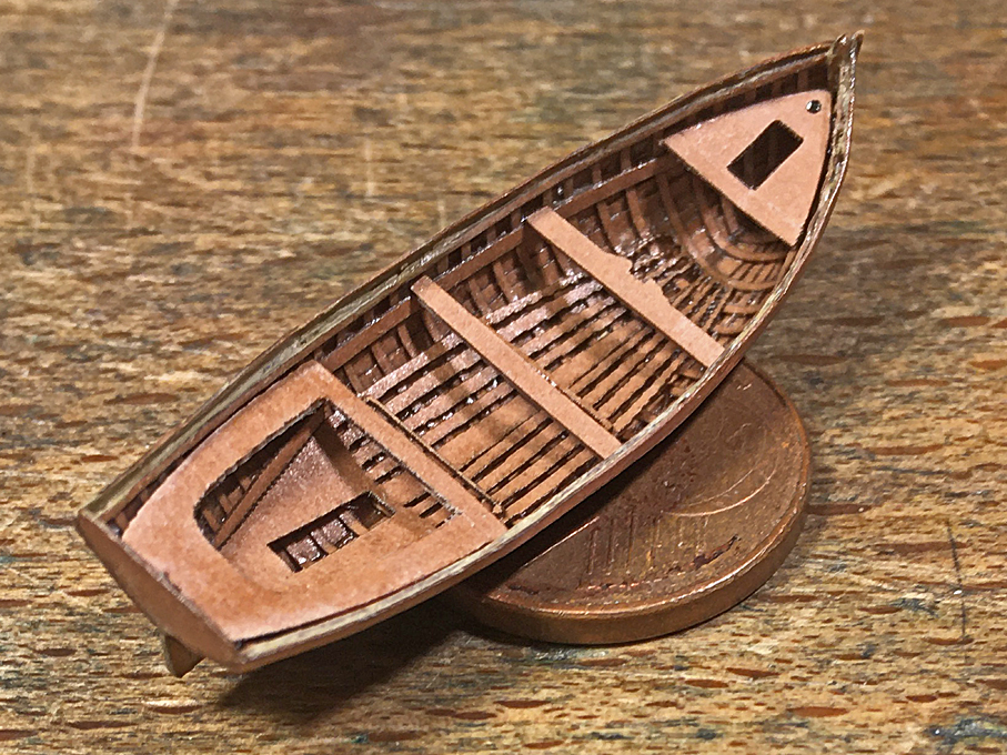
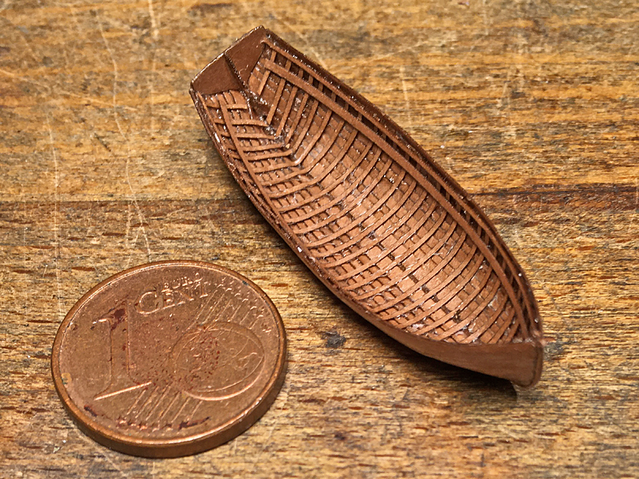
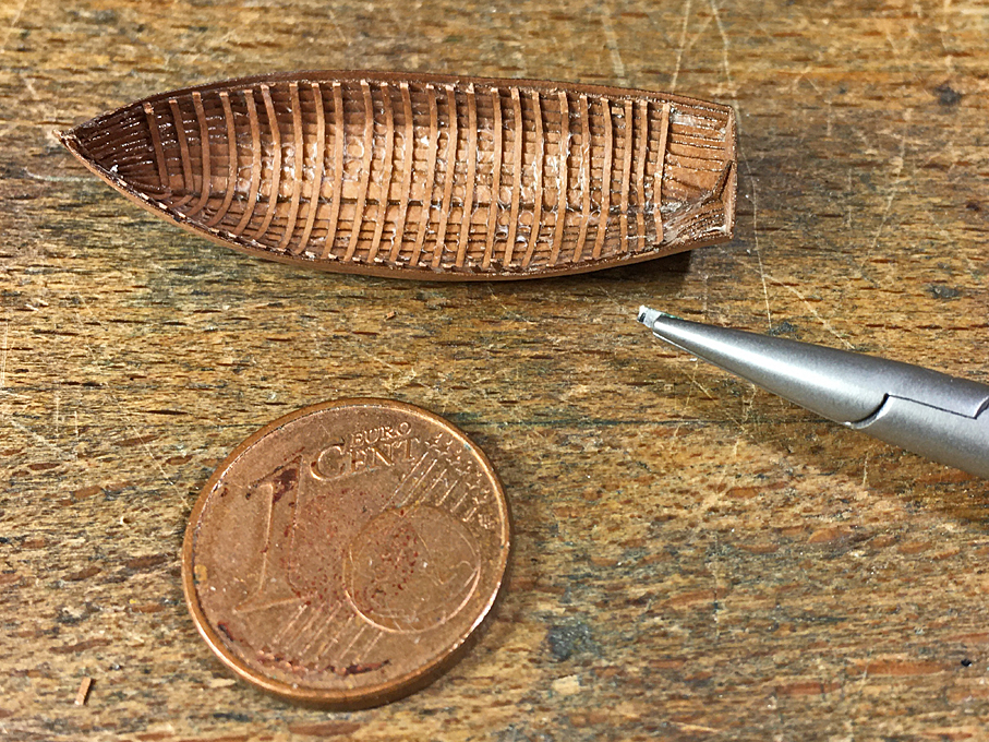
Thanks again for the friendly encouragement! ********************************************** Jolly-Boat continued 4 After some deliberations, I decided to cut the top of the frames back to gunwale level using a sort of micro-scalpel made from a piece of razor-blade just under 1 mm wide and held in a holder meant for that purposes (they come from the biological/medical realm). Hull with frames cut back to gunwale level Next went in the gunwale, laser-cut strips of paper 0.35 mm wide and 0.12 mm thick, and the inwales on which the seats rest, 0.5 mm x 0.12 mm. These were all lacquered in. Hull with gunwales and inwales On the prototype the floorboard, of course, were individual planks, but aligning them properly would have been rather difficult, so I cheated a bit and joined them. This will be barely visible under the seats eventually. Floorboards installed in the hull As my building was not as precise to the drawings, as I would have wished, the stern-sheets and the little platform in the bow required a bit of trial and error, and re-drawing for the laser-cutting. Still a bit of sanding to fit was required. Sanding paper is not that much fun, but re-soaking it in lacquer after a few strokes with a diamond-file keeps fraying under control. Stern-sheets, rowing seats and bow-platform installed I also laser-cut some foot-rests for the rowers – these parts are double layers of paper, with the actual rest about 0.2 mm x 0.2 mm in cross-section The footrests for the rowers are visible just before the rowing seat behind This concludes the main structural parts, but a lot of small bits and pieces still need to be done.
- 873 replies
-
- 28
-
-
