Anguirel
-
Posts
45 -
Joined
-
Last visited
Content Type
Profiles
Forums
Gallery
Events
Everything posted by Anguirel
-
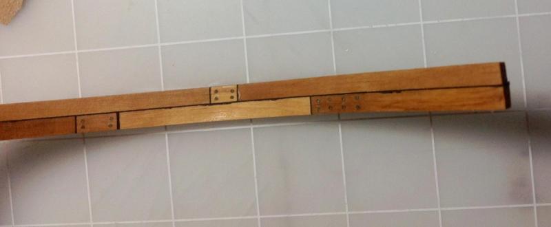
Hi, So I finished my first double frame. This was done mainly for testing since the frame is wrong some time now... I think the treenails and copper nails came out alright, the copper nails more then the treenails. One half The other half The treenails And the treenails on the scarph I realised now that the treenails on the scarph should had gone through to the other side. But should the same thing be done on the chock? For the finish I was planning on using Danish oil but I must admit it let the wood darker then I was expecting... One half The other half The treenails While I was putting the treenails I used a pencil to "paint" the treenails black but most of it came off during the process of applying the treenails to the frame. At the time I was worried that the black wouldn't show but I guess I was wrong. I ordered wood from The Lumberyard and from Hobby Mill, although the are the same wood type (boxwood) there are not the same... For last... next time have to be more careful to maintain the frame square when doing the holes for the treenails. This is a stupid way to ruin a frame almost at the end

-
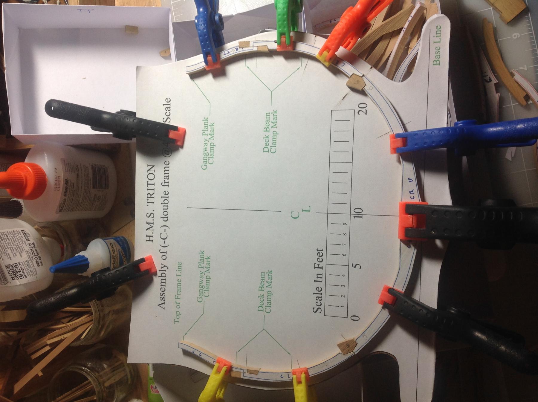
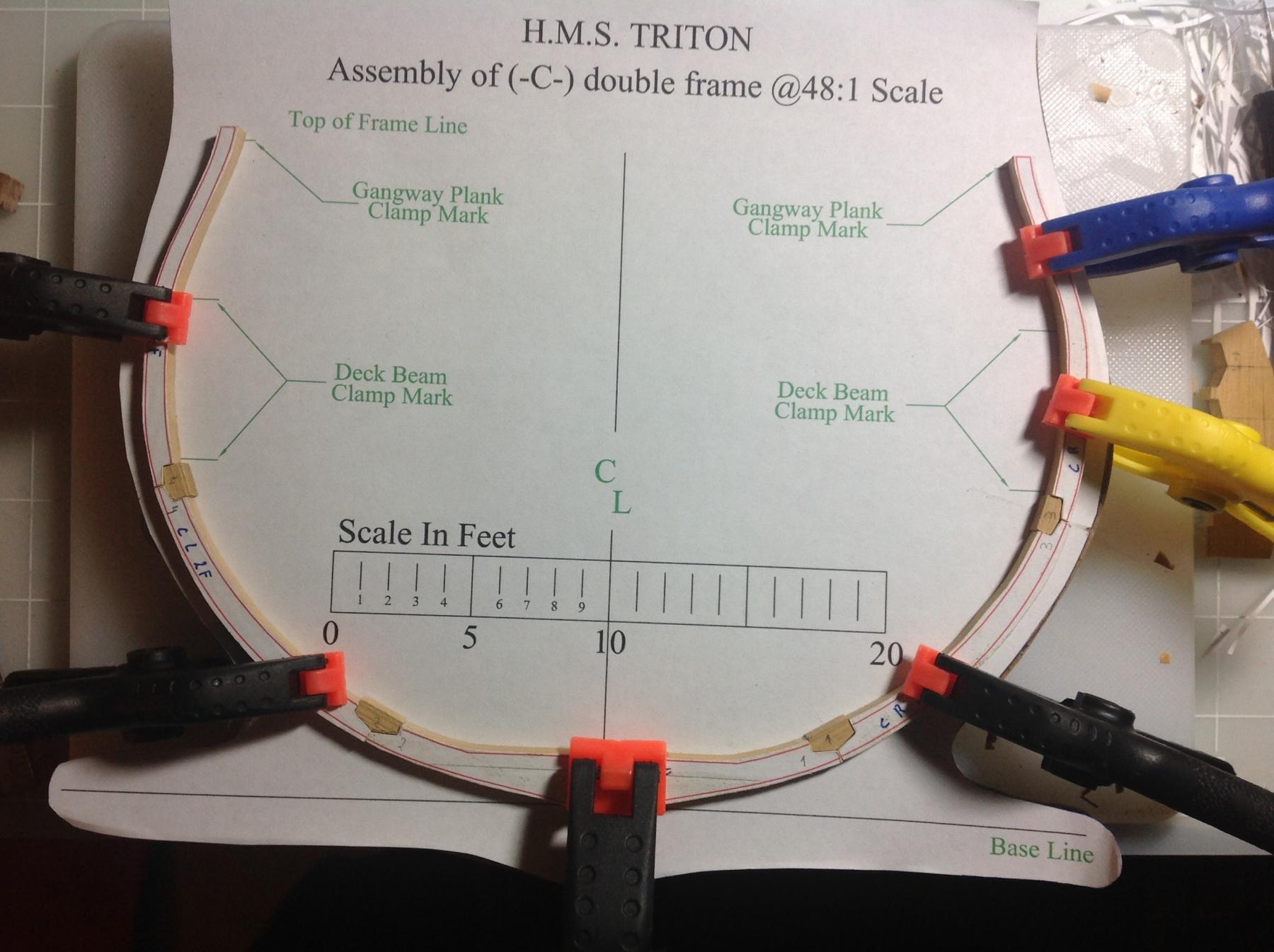
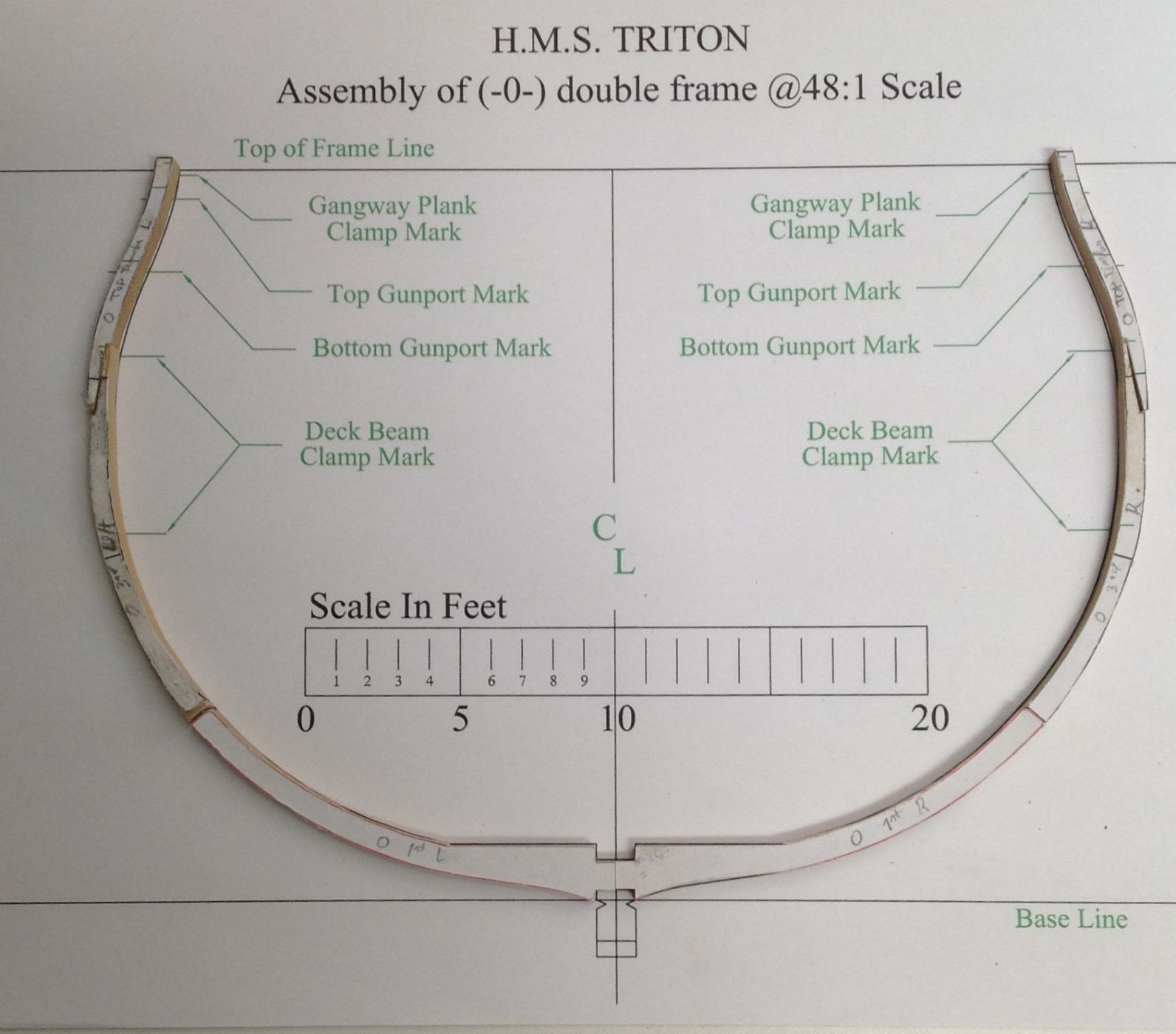
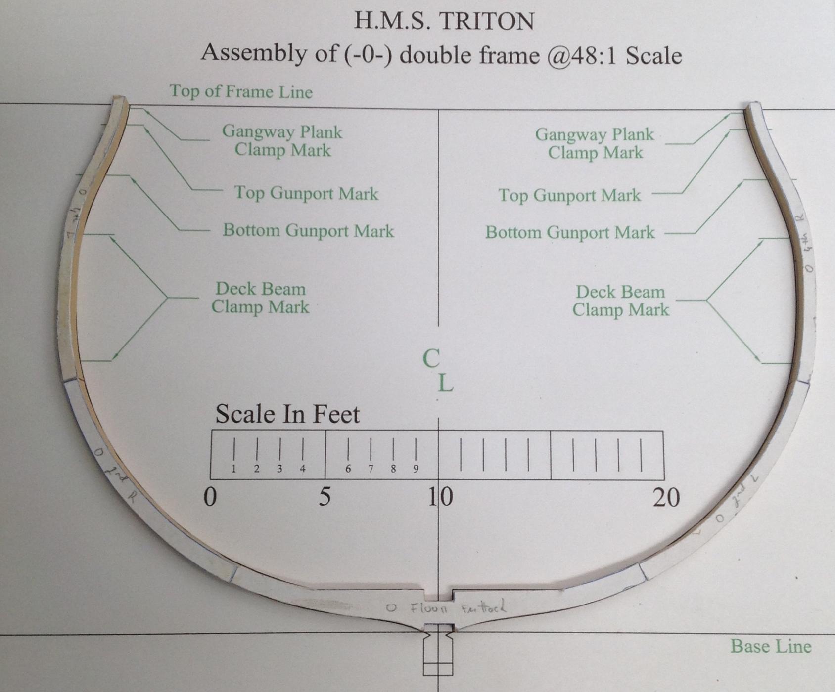
Hi, "and very nice it is too! That must have been very satisfying to make. Tony" Thanks Tony, it was indeed very satisfying... Mike, align the pieces wasn’t difficult, just used the plan as a template. What was difficult was sanding the individual half frames and putting the two half’s together. The frame pieces, chocks and futtocks were sanded and aligned before and everything was perfect. Once I put the paper on this added an extra length (the thickness of the paper) to all components and everything had to be re-sanded and the chocks had to be re-dimensioned. Next time this can be avoided by taking this in consideration from the beginning. Another problem was that the glue doesn’t form a solid joint across the paper so it’s very easy to pull the pieces apart (this happened three times during sanding) leaving paper on both sides. This doesn’t happen once the two half’s are together. Now what I don’t know how to do is how to put the two half together. This time I did it with the two half fully assembled. There is a post called “Assembling Frames” pinned to the top of the cross section section that shows how to do this adding piece by piece of the two half at the frame time. First the floor futtock, then the 1st futtock, then the 2nd and so forth... now my question is how do you align them if all the pieces have extra wood on the side, how do you align the red and blue line if they are not always at the same distance from the edge of the different pieces (when I did mine, I cheated, I sand it first so the lines where at the edges). Christian, your help is most welcome and needed. Some questions and observation from the image you posted 1. The frame at station 0 is not double 2. The double frames at station 1 and (A) are not symmetrical, the half’s closest to frame 0 are thicker 3. Frames at station 3, 5, 7, A, C and E are symmetrical 4. The frames at stations 7, 5, 3, 1, (A), A, C and E there is a space between them from the 1st futtock up while the frames at stations 6, 4, 2, ? (what is the name of the station between (A) and A?), B and D there is a space between them all the way from the keel 5. What are the units of the thickness values written in the image? 6. When you say all other frames have normal thickness is that the thickness used in the plans here at the forum? If that is the case I can use the pieces I have already cut and just sand then to the correct thickness (assuming they have the thickness of the floor futtock all the way up). Only have to redo the frame 0 and the two half frames from station 1 and (A) 7. The frames at stations 7, 5, 3, 1, (A), A, C and E at the connection of the different pieces there are 4 horizontal lines (two at the 2nd-3rd futtock joint) in the space between the half frames, are those the location of the frames spacers? or just the location of the copper bolts? 8. How do I determine the size of the space between the frames, they don’t seem to be always the same 9. The frames at station 6, 4, 2, ?, B, D there seems to only be a reduction in thickness from the floor futtock to the 2nd futtock and from the 1st futtock to the 3rd futtock. The 2nd, 3rd, 4th futtocks and the top timber have the same thickness Jan, I already used this paper in the same way in one of my kits and it didn’t bleed to the wood but I will test this on the frame I’m doing now Just a small update on the frame I’m doing… the treenails are in place as well as the copper wires. Once everything is sanded I will post picture Thanks everyone for the likes, comments and help…
-
Hi, Anobium what a wonderful idea... when you say 3 thick frames at station 0 are you referring to the changes in thickness as we go up? The first biggest problem about this idea is that I still can't understand everything in those kind of plans. But I will try. As for the frame I was building I used black paper to simulate the pitch and tar that was used. This introduced a extra high to the floors, futtocks and top timbers that I was not successful at compensating and one side of one of the halfs is bigger then the other. I also had to compensate the size of the chock and scarphs. Because of this (and Anobium's idea) this frame is now garbage. I still used this frame to do some testing and to see the final result of using the black paper One half... The other half... And the inside... Now for the treenails. I will try boxwood (same wood as frames) for the treenails and copper wires for the nails. Let's see how it looks


- 59 replies
-
- 10
-

-
Thank for the kind words Tony. It just makes me nervous knowing that there is a "righter" way to do it. Don't get me wrong I'm very appreciative of the free work that was put in making the planes and I understand the need for simplicity in this kind of projects but I feel wrong if I don't go the extra mile. So with that in mind here's my attempt at the cross chock Only 8 to go...

-
Hi, One question about frame construction. The Triton's keel was layed down in 1771 and according to Peter Goodwin between 1750-1811 the 1st futtocks ended in a scarph against the keel and a cross chock as used to fasten the two and the assembly to the keel. On the plans the two 1st futtocks are actually very similar to two half floors. In this case (again according to Peter Goodwin) they would be fastened to each other and to the keel by coaks, this was the method of construction between 1811-1850. So the question is: where the plans simplified so "first times" like me could actually build the cross section and I'm over complicating or is there and alternate method of construction? I'm sure Peter Goodwin's word is not the only one and it's not final. Thanks
-
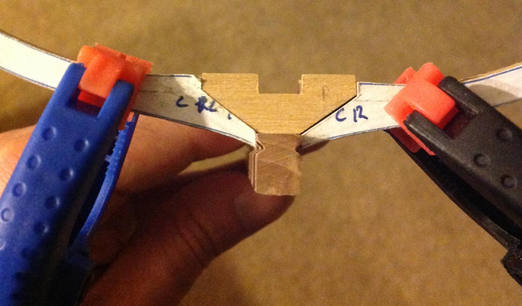
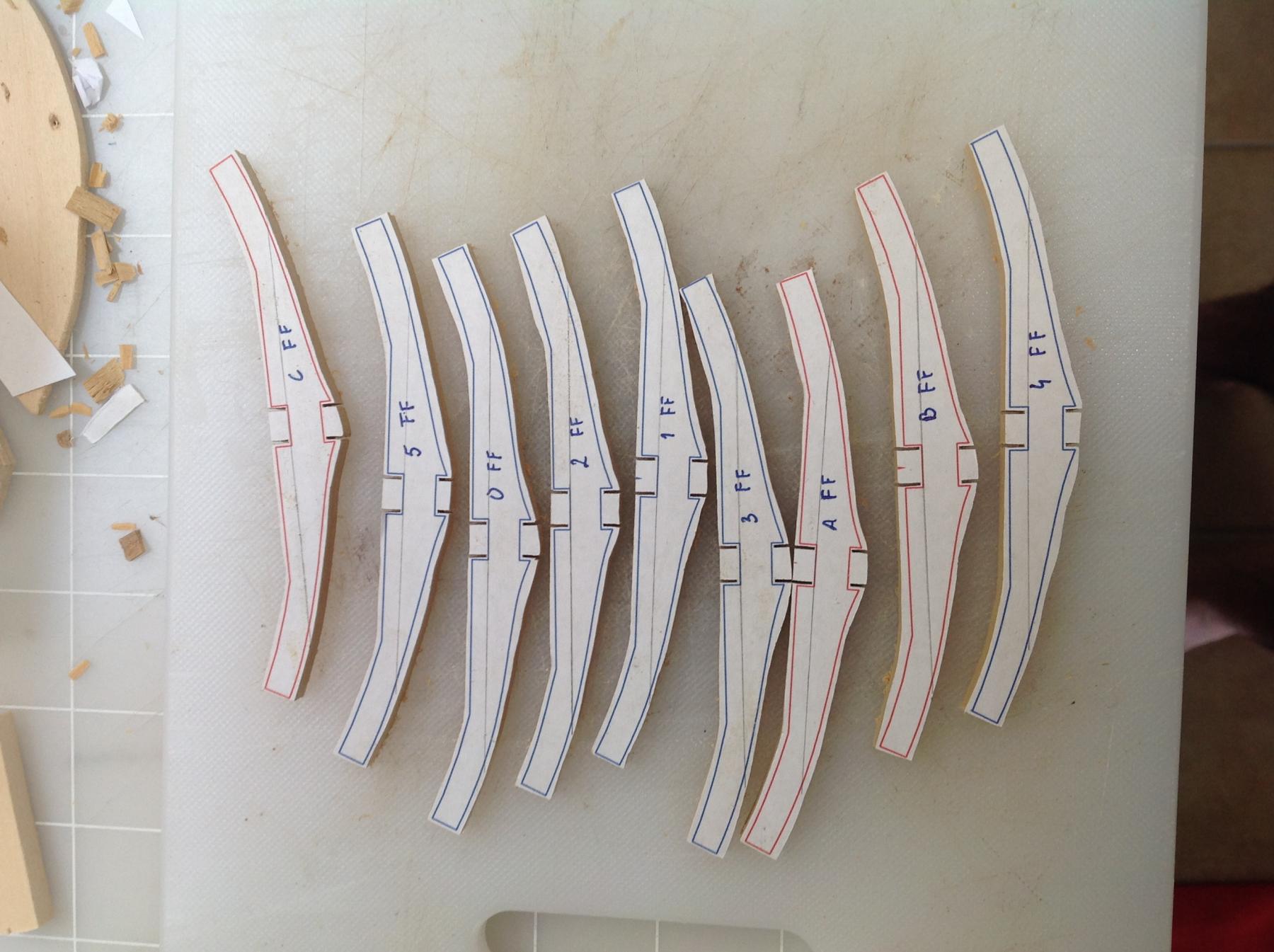
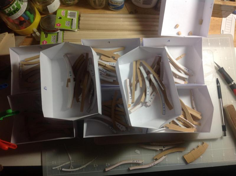
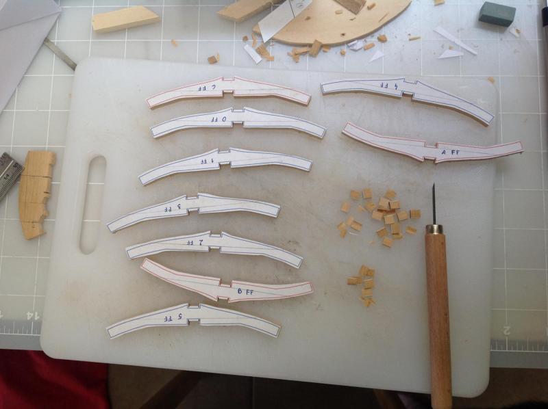
Hi, GabeK, thanks. I did see your log during my research but like.you said it's difficult to find the formula for the chocks dimensions. I did find one on the TFFM book but I'm missing one of the variables. I ended up simplifying the formula. I cut all the frames peices, still can't control the scroll saw properly so some are closer to the line then others. In the mean time finished the "C" double frame. The second pair has 2 chocks and 2 scarphs. With the mill the scarphs where much easier to make. Still there is a lot of fine sanding with the micro files... Now to glue everything, sand and then treenails...
-
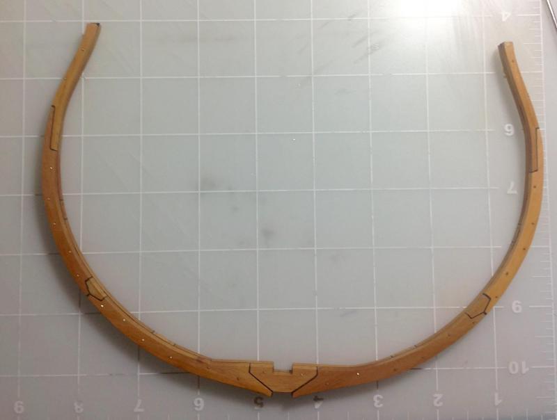
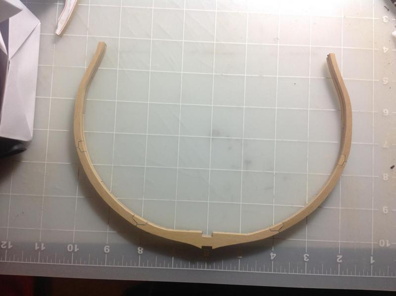
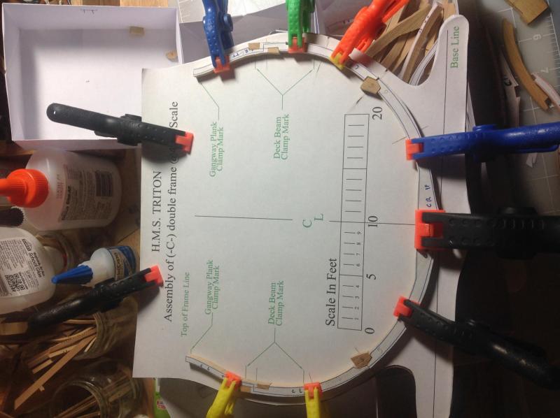
Hi, Today was a better day. My first half frame with chocks is ready... Tomorrow for the other half. Thanks for all the likes.

-
Hi, Looking at the book "The Arming and Fitting of English Ships of War" by Brian Lavern the port tackle (in the book it's called Gun Tackle was used to run the guns out. it was fixed to the side of the gun carriage thought a eyebolt or ringbolt. To the hull it was fixed on the eyebolt above the eyebolt of the breech rope. The train tackle was similar to the gun tackle, except that it was fixed between the gun and a ringbolt near the centre line of the ship. The train tackle was used to keep the gun in place when reloading. According to the same book there where several problems with traversing the guns from side to side: the narrowness of the gun port, the fact that the gun carriage wheels only went back or forward and the effectiveness of the side tackles was limited due to the position of the ringbolts on the ship's side. So the crew was expected to manoeuvre the guns using crows and hand spikes. Hope that helps
- 16 replies
-
- 3
-
-
- Gun tackle
- Triton cross-section
- (and 2 more)
-
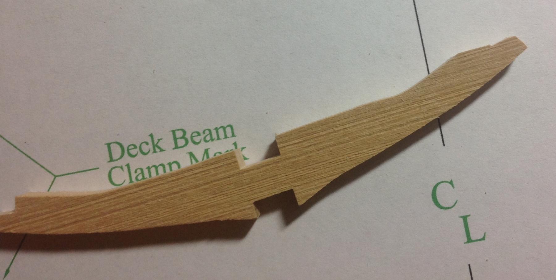
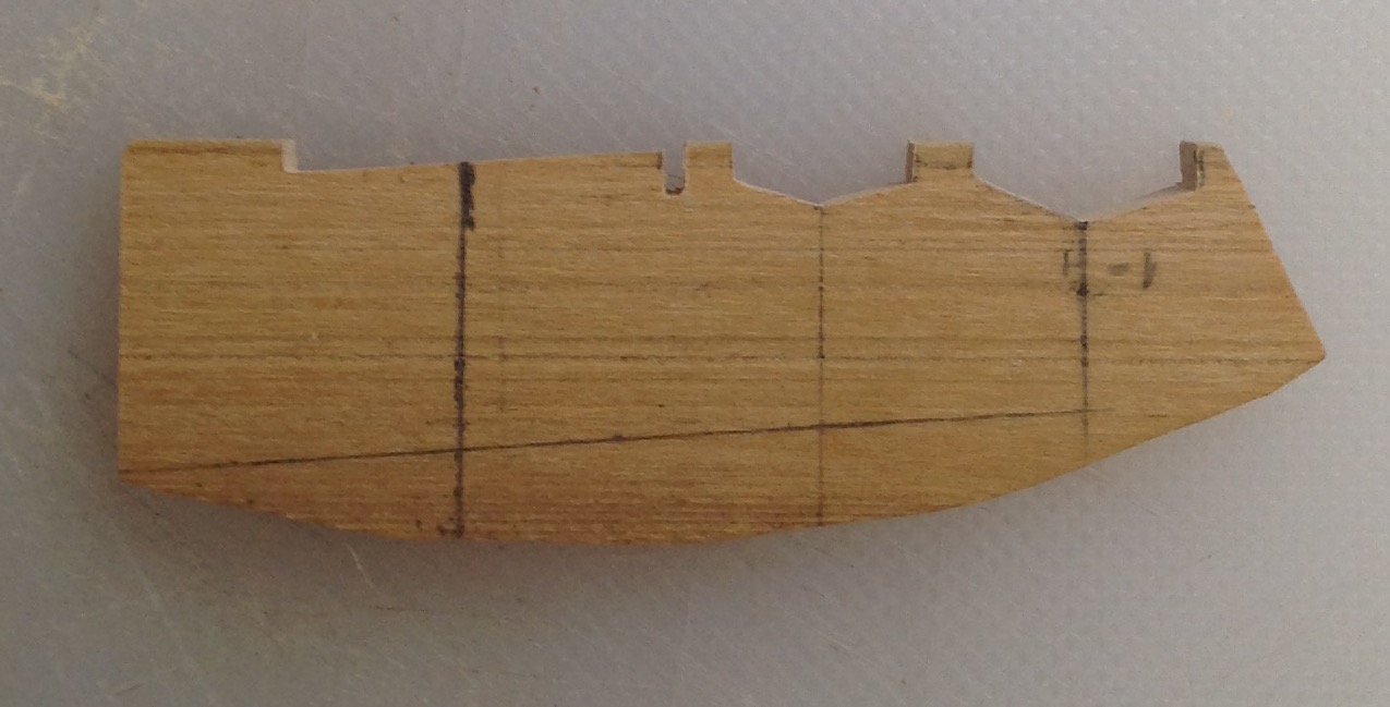
Hi, Another day of ups and downs. I cut the flat futtocks and used the scroll saw to cut the guides for the keel and keelson slots Then used a flat carving knife to cut the excess and prepare the pieces for the mill so I have nice squared, flat surfaces And after the mill Next phase was the chocks, I cut the edges for the first two of the "C" frame But was can be seen the one on the left suffered a fatal accident. I was cutting the angled face with a x-acto blade and because I was cutting parallel to the wood grain it just cut the egde off. Basic mistake... I still used the other edge to make the other chock It came out better then I was expecting for the first one Now to redo the flat futtock...


-
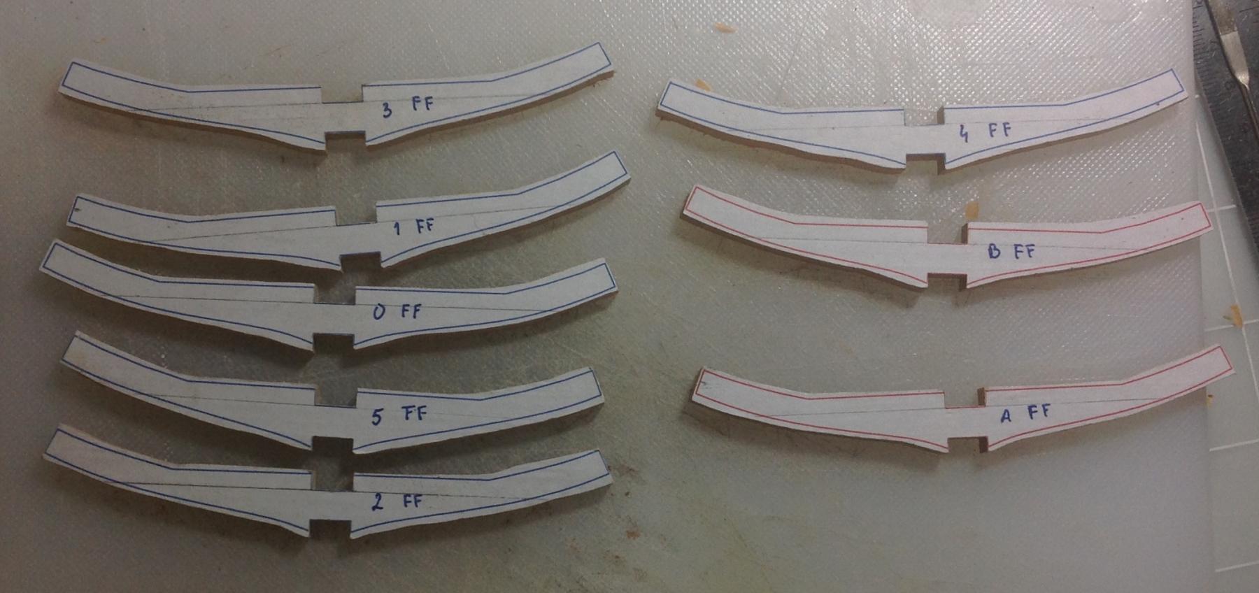
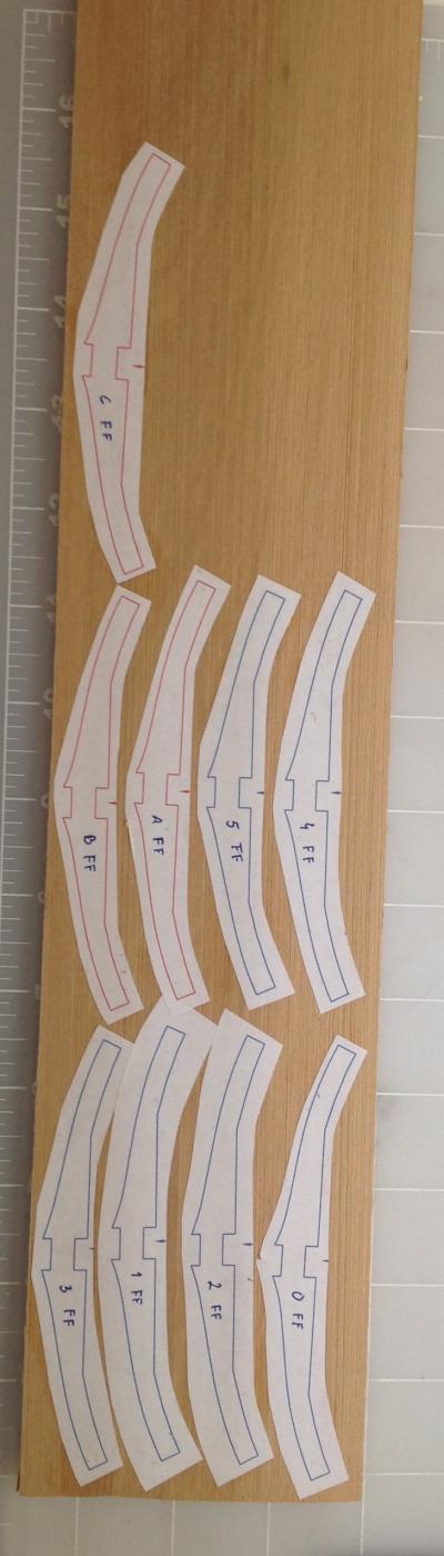
Hi Found some information on the TFFM and decided to take the plunge. Used Kevin Kenny's idea and build a gig with the different sizes of the chocks and the futtock The floor futtocks are glued to the boxwood and ready to cut... Time is limited let's see if I can finish them today. Thanks

-
Hi The line relieving tackle (5) went to the rear eyebolt and it was used to run the gun back for loading. It would be attached most of the time but not in the configuration shown in the image. Most of the time the guns would be secured for sea. They would only be in that position during actions. If you want more information about how the guns were operated see this link http://www.navyandmarine.org/ondeck/1800gundrill.htm Hope that helps...
- 16 replies
-
- 4
-
-
- Gun tackle
- Triton cross-section
- (and 2 more)
-
Isn't that the line used to run the gun forward?
- 16 replies
-
- 4
-
-
- Gun tackle
- Triton cross-section
- (and 2 more)
-
Hi, After a brief pause to make a Christmas present I'm back on the Triton. I has planing on doing the frames with chocks but I can't find dimensions anywhere. I've looked in Goodwin and The Fully Framed Model volume one and although in the first there is a detailed description of the futtock there is nothing on the chocks. On the TFFM there is a detail description on how to make the chocks but they are in the planes so there is no information on there dimensions. I looked in all logs of the cross section here at the Forum (as well as the full build) and no one used chocks in there respective builds. Iwas going through the full build planes and I did find one sheet titled "Chocks @48:1" is this where the dimensions of the chocks are? Are they all the same size independent of the size of the frame? And are the planes only showing half the chocks? Thanks
-
Hi Chad, Thanks for posting this again, I already learned a lot... Just one question about the treenails, I have looked in the other logs but I can't find one where the wales were treenailed (maybe difficult to see it he images?). In the case of your wales (and some others) you used ebony. In that case the treenails should be made of ebony as well, right? How difficult it will be to make the treenails with the method you used? Thanks.
-
Hi, Thanks for the comments and likes. Leaving a bit of wood on the sides seems logic in order to have an uniform surface after assembly. My question in this case is if I'm using treenails or copper wire to simulate nails fastening for the futtock and chocks, since these will be on the inside should I do them after assembly and fairing? Thanks
-
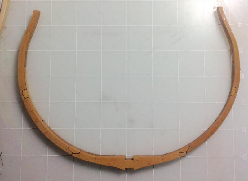
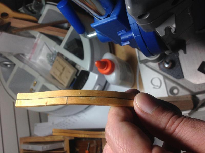
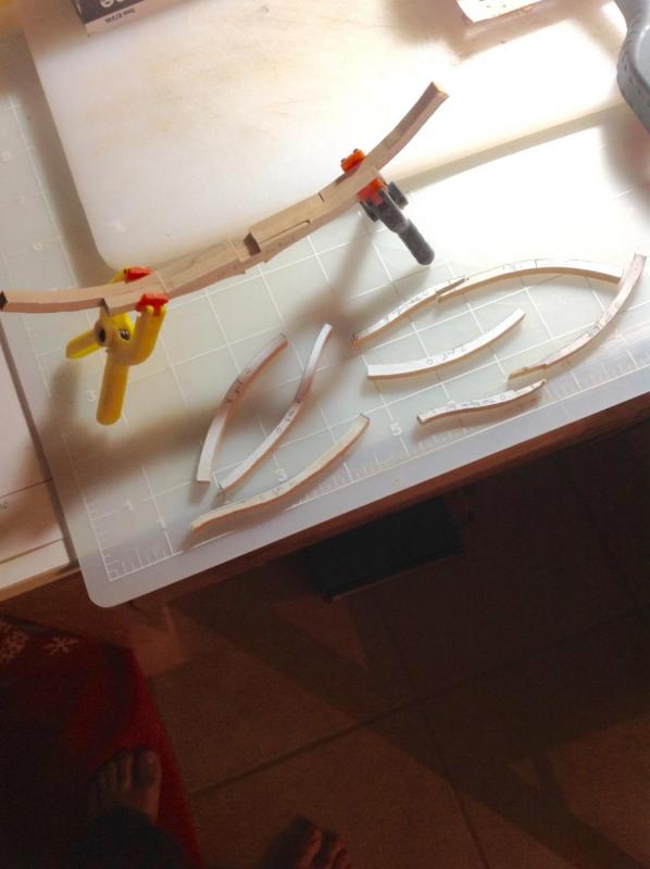
Finished what I could with is first try. On this pair the left side scarph is broken. I first try to do it with a carving knife but when doing the flat part of the scarph the corner of the edge broke. The others were done with the mill. I guess I have to make a jig because even with the mill the angle of some of the flat parts scarph are wrong so the top timber doesn't align with the plans. For the second pair the floor futtock is wrong. For some reason the right side of the floor is lower them the left one. I'm still using this pair to train the chocks. I've faired the frames to the inside of the line which I was already advised against... So after trying the chocks is back to doing a new pair. Thanks.
-
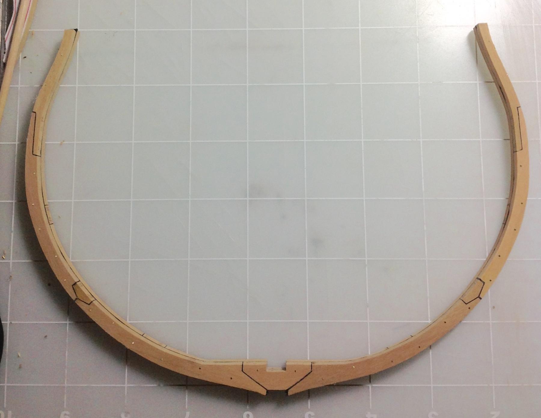
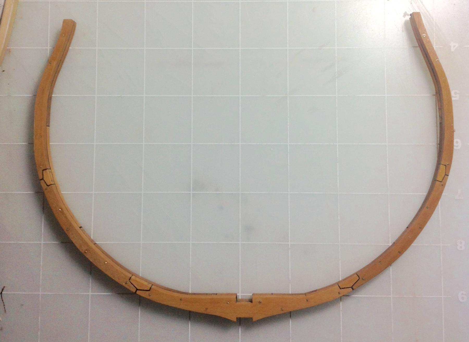
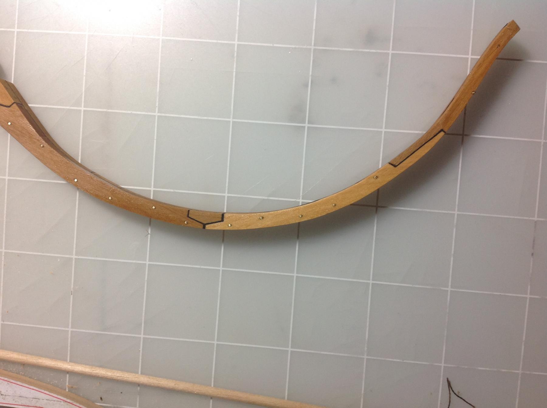
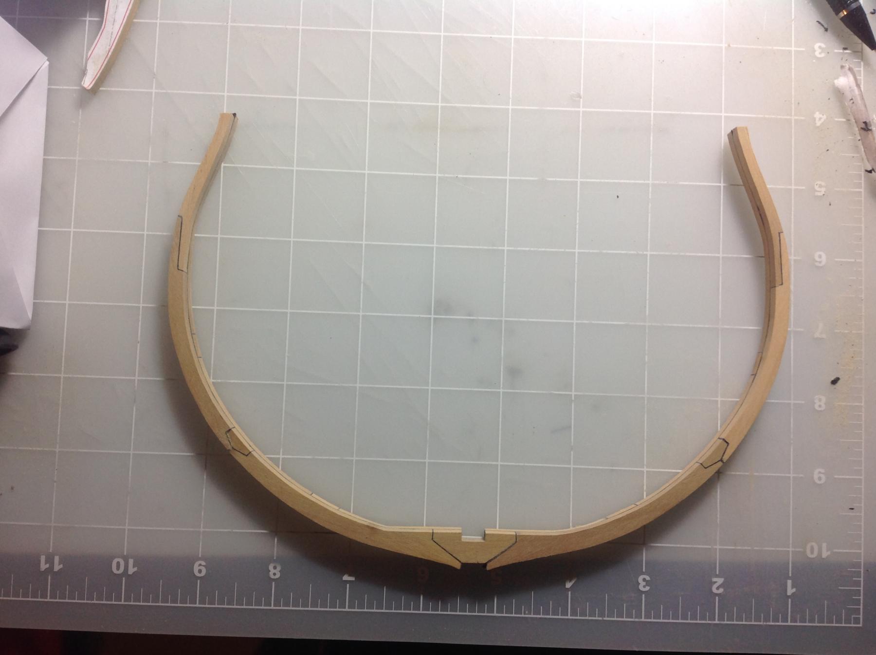
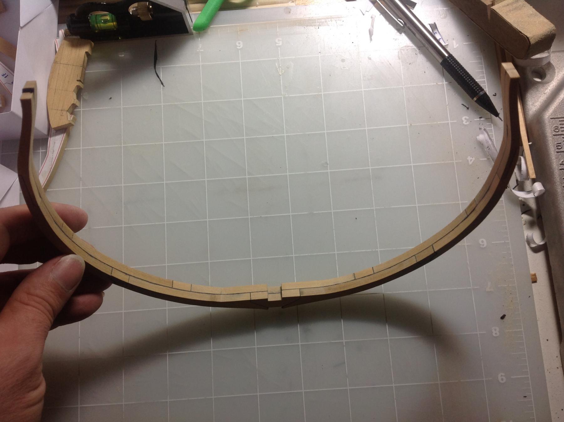
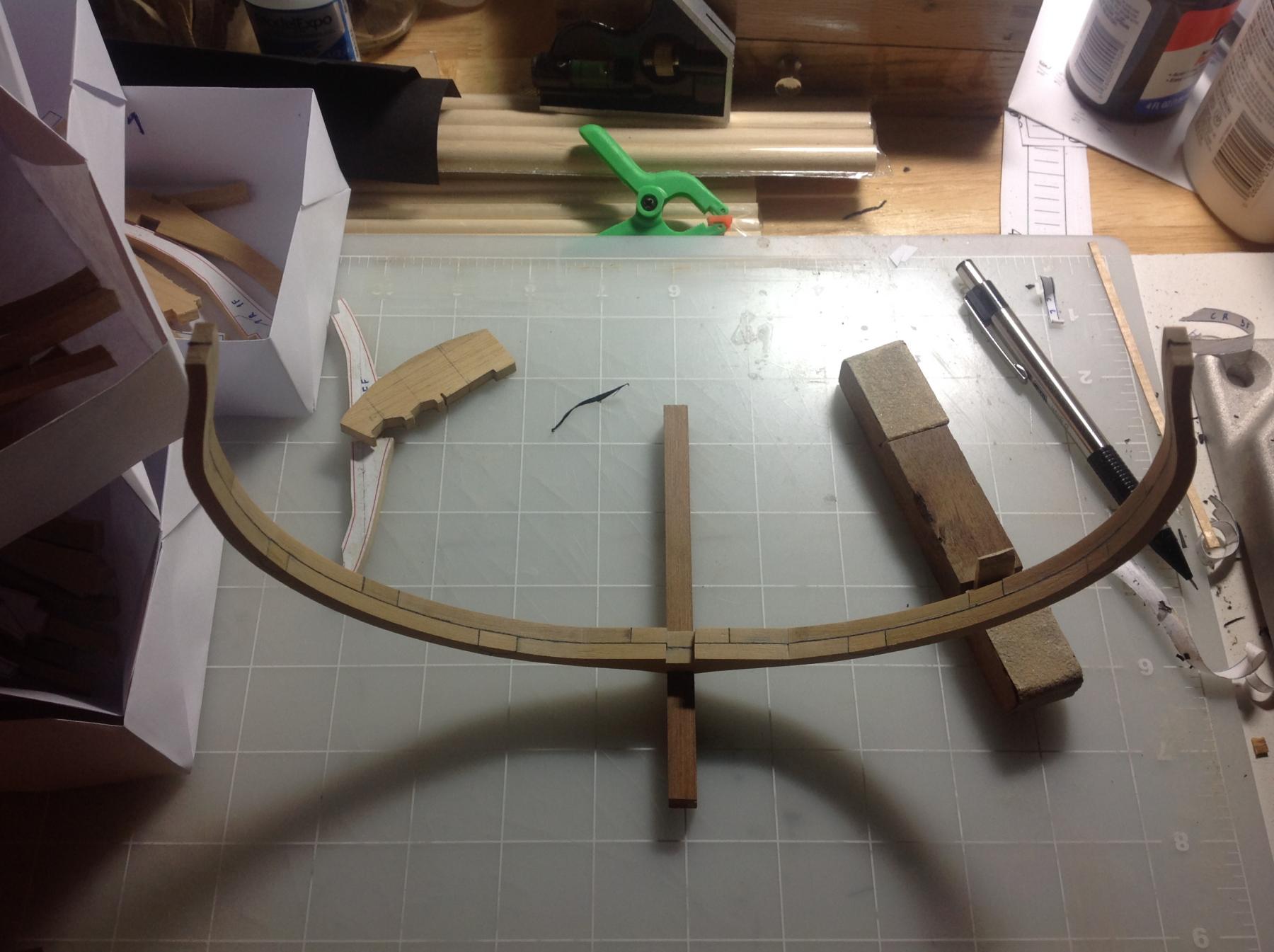
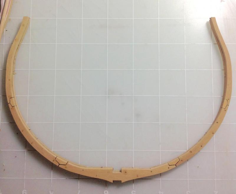
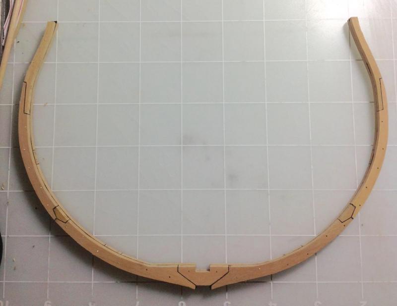
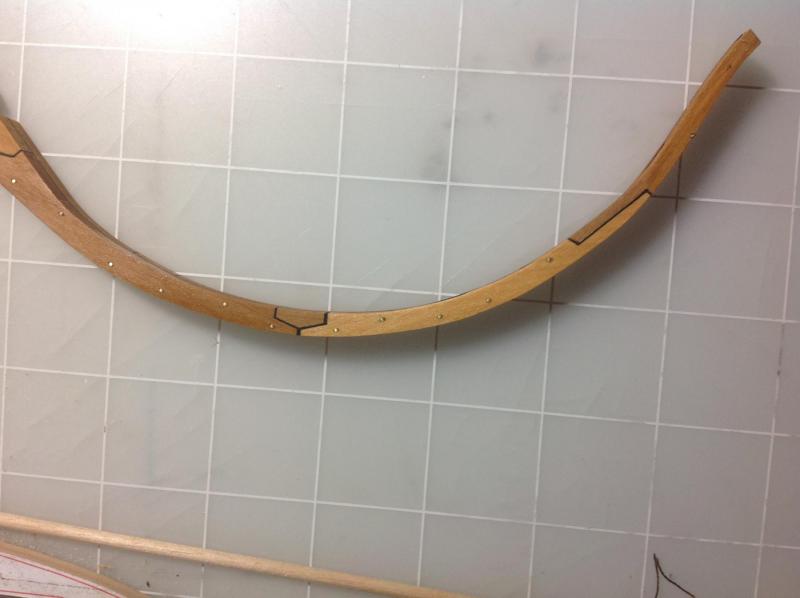
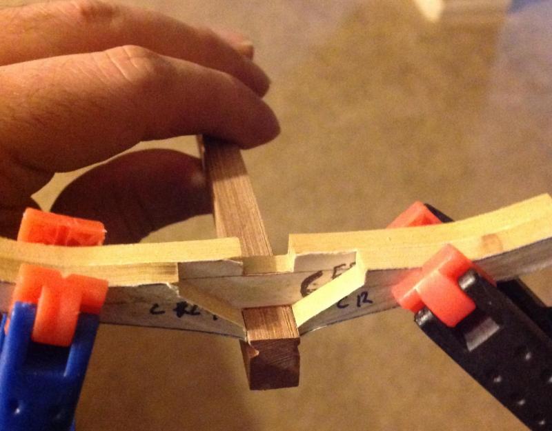
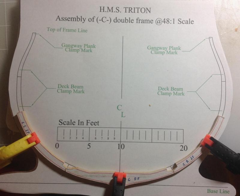
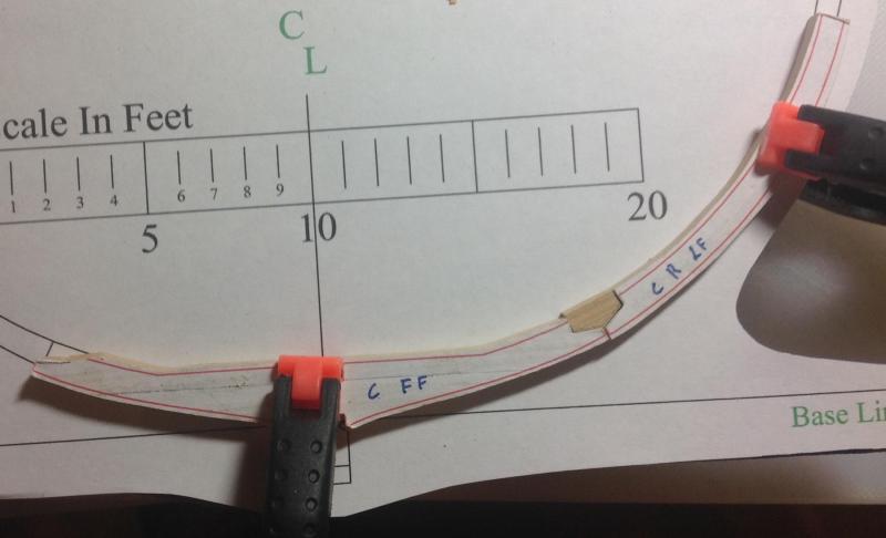
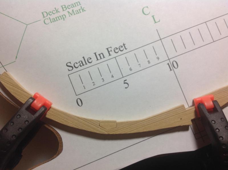
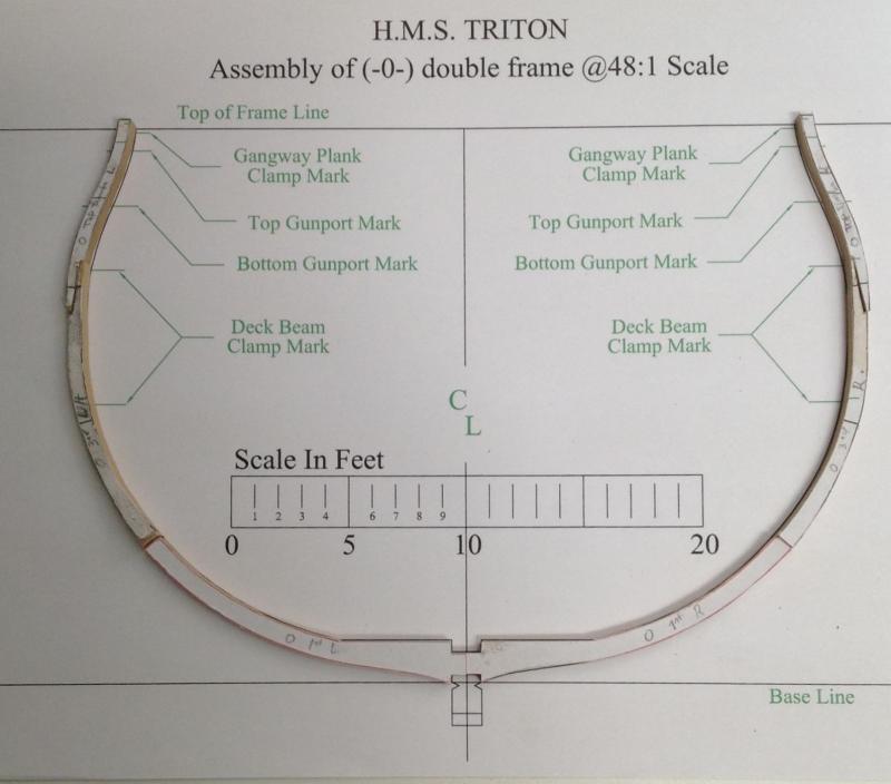
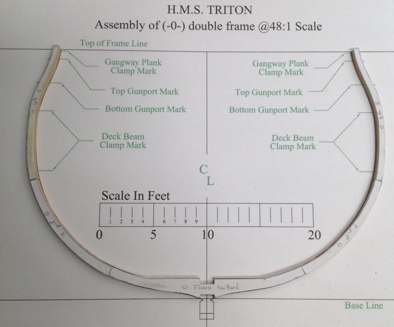
Hi, Today I finally had a few moments to try the frames. I've been doing some research on the frame joints... and I found an answer in Peter Goodwin's book. All joints were made with chocks except the joint between the 3rd and 4th futtocks and the respective top timbers that was made with a plain scarph. Here's how mine are coming along (sorry about the quality of the picture it was taken with the kids sleeping and with the iPad) There is only one thing I could not find: a formula for the dimensions of the chocks. I found the dimensions for some chocks for the Victory and extrapolated a formula. Chock width: 3 times the thickness of the frame and chock height: 3/4 of the frame height. Is this a good approximation? Does anyone found and actual formula? One other question: are the frame joints (and the connection of the double frames) supposed to be caulked? Hope that tomorrow I will be able to finnish preparing frame 0
-
Thanks for all the welcomes and likes. ChadB I don't mind the lack of sanding although the not squared this is too much for me. If I had the proper tools to do that I wouldn't need to order milled lumbe. But if this is done by conviction and not by incompetence and if it's a more or less well know fact in the community I'm ok with it. Next time I will be more specific on how I want my order or go to a different place.
-
Hi, Thanks tkay11 and mtaylor. I'm living in the US, I did't want to name names in case it was something due to ignorance on my part, which seems to be the case. Next time I will ask for the wood to be cut at exact dimensions and sanded. Thanks
-
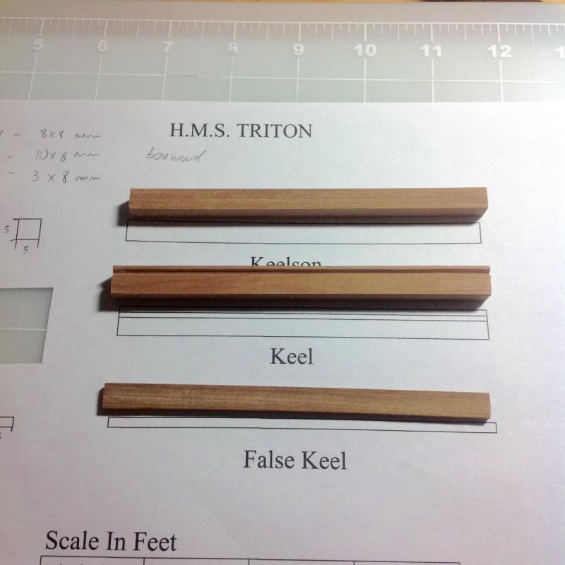
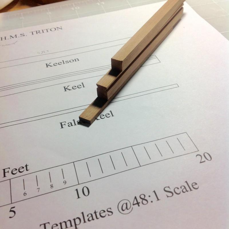
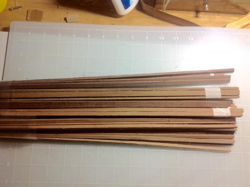
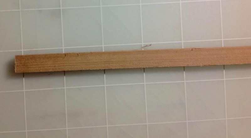
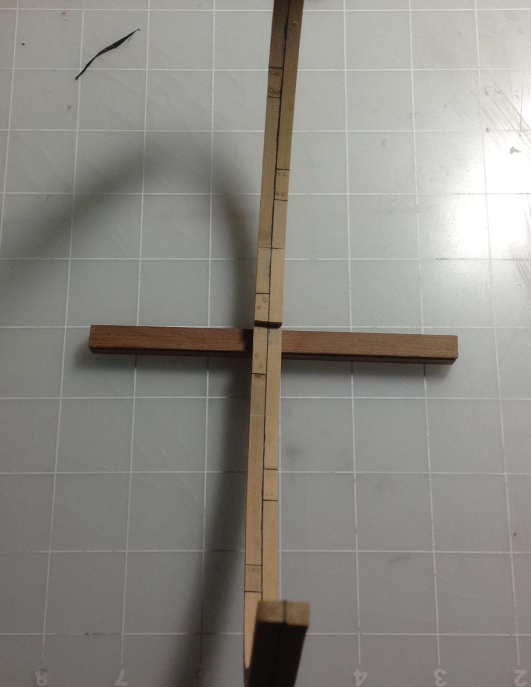
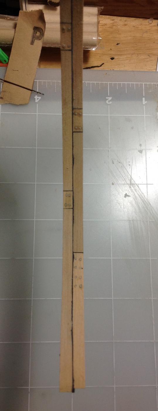
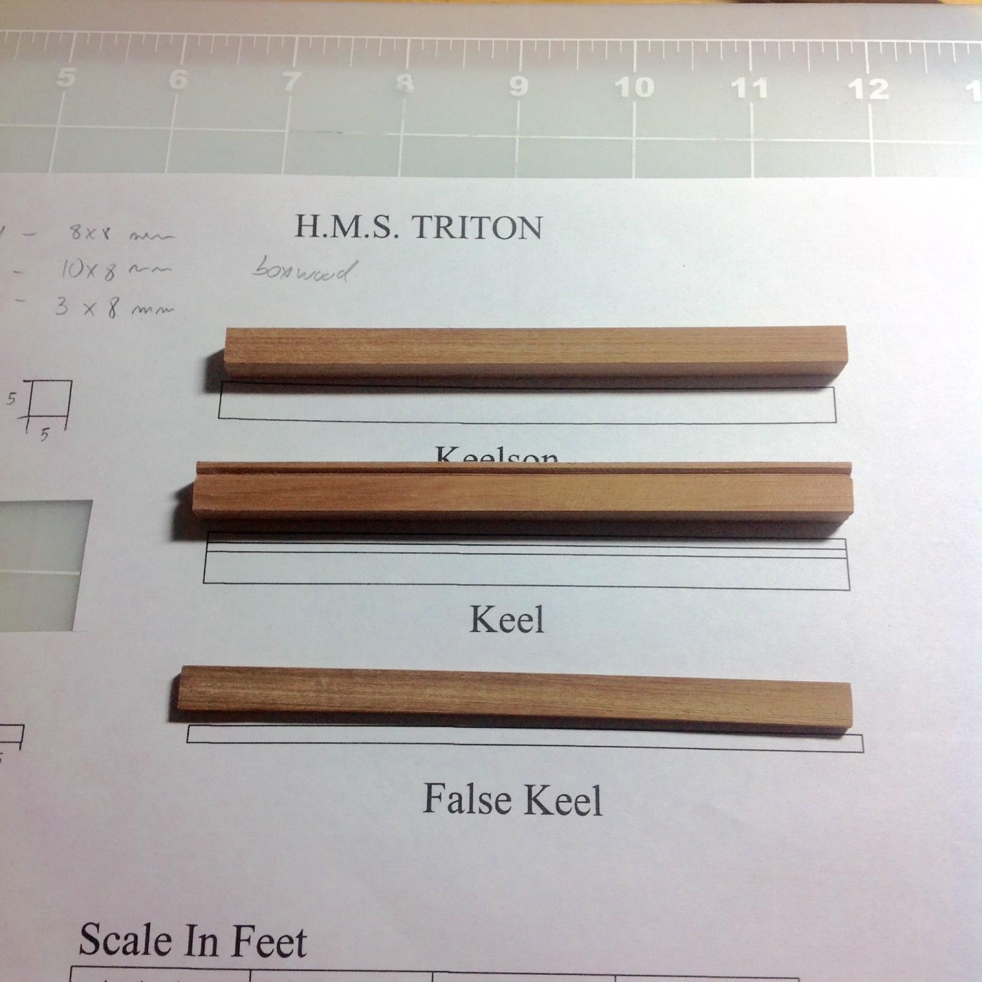
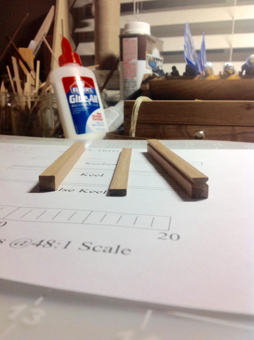
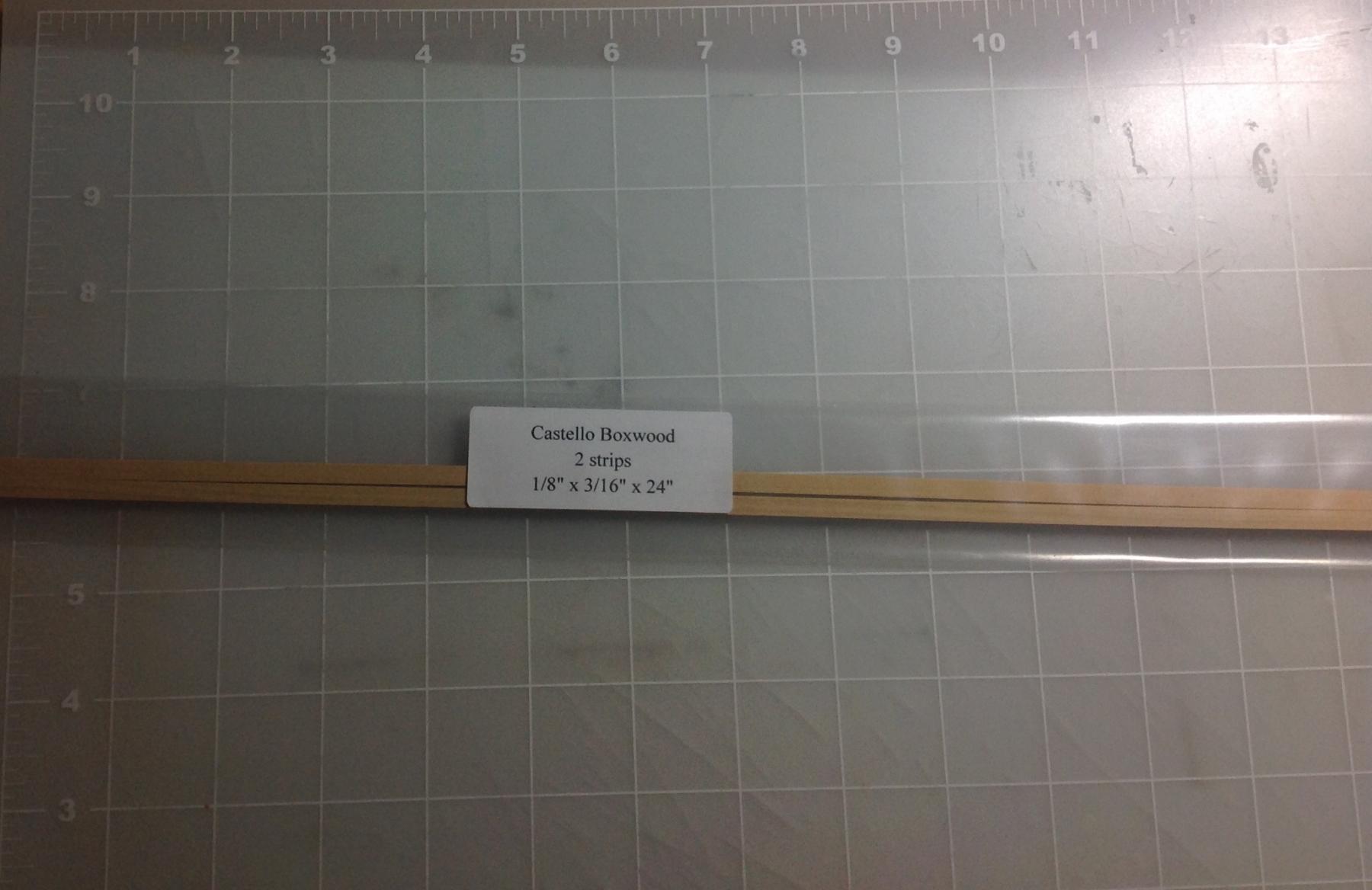
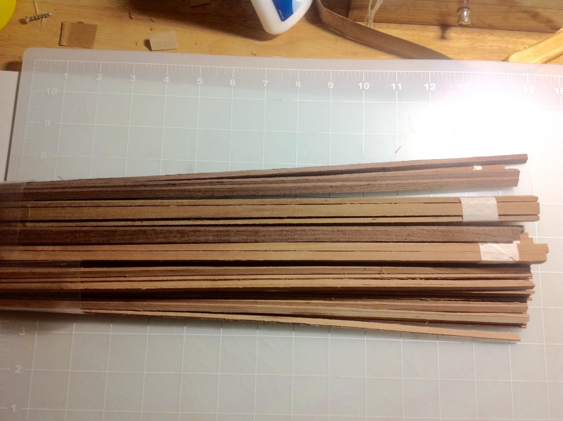
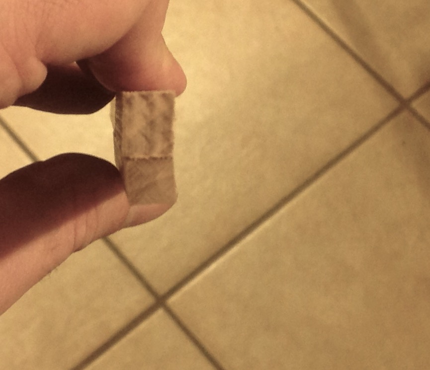
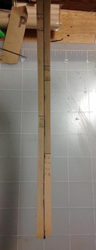
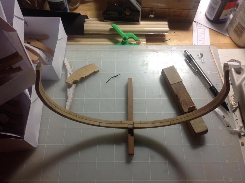
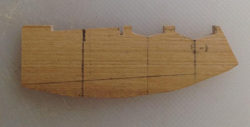
Hi all, I have been following many off the logs for years now. I have built two ships and I'm half way through the Santissima Trinidad (kits) but I was always amazed with the models on the scratch build section... i finally mustered the courage to try one myself. The Triton cross section seemed the perfect candidate, not too big, not too small. And the Group Project give the necessary support to new people like me.I ordered the wood from the wood list in the first post and I started as soon as it arrived. I have the three peices from the first drawing ready and now request access to the rest of the plans. A side note about the woods I'm using. Like I said I order the wood list from the topic's first post. I contacted two online stores and gave them the wood list. One of the stores said they didn't had some of the wood types I was requesting so I ordered the all lot in boxwood. This was the store that replied first. One day after paying I got the answer from the second store. They had all the wood types I wanted for a bit more them the first. Since I wanted to test different wood as well I proceeded with the second order. The problem was when the wood arrived. From the first store (just boxwood) the wood arrived like this: All strips of wood in individual labeled bags. The wood from the second store arrived like this: No labels with sizes or wood type which made it very difficult since I don't recognise the woods. One other difference was the finishing the wood from the second store they weren't sanded The biggest problem is that some the wood from the second store is not squared The keel (in the image) was one of the strips that was not squared. My question is: is this normal? Or this is something I should complain? Specially the not square thing, which just adds another level of complication... Thanks in advance, Anguirel