Anguirel
-
Posts
45 -
Joined
-
Last visited
About Anguirel

- Birthday 02/26/1979
Recent Profile Visitors
1,272 profile views


-
 GrandpaPhil reacted to a post in a topic:
Nau Rainha de Portugal 1791 by Anguirel - 1:46 - POF - 74 guns
GrandpaPhil reacted to a post in a topic:
Nau Rainha de Portugal 1791 by Anguirel - 1:46 - POF - 74 guns
-
GrandpaPhil reacted to a post in a topic:
Nau Rainha de Portugal 1791 by Anguirel - 1:46 - POF - 74 guns
-
ccoyle reacted to a post in a topic:
Nau Rainha de Portugal 1791 by Anguirel - 1:46 - POF - 74 guns
-
Wintergreen reacted to a post in a topic:
Nau Rainha de Portugal 1791 by Anguirel - 1:46 - POF - 74 guns
-
mtaylor reacted to a post in a topic:
Nau Rainha de Portugal 1791 by Anguirel - 1:46 - POF - 74 guns
-
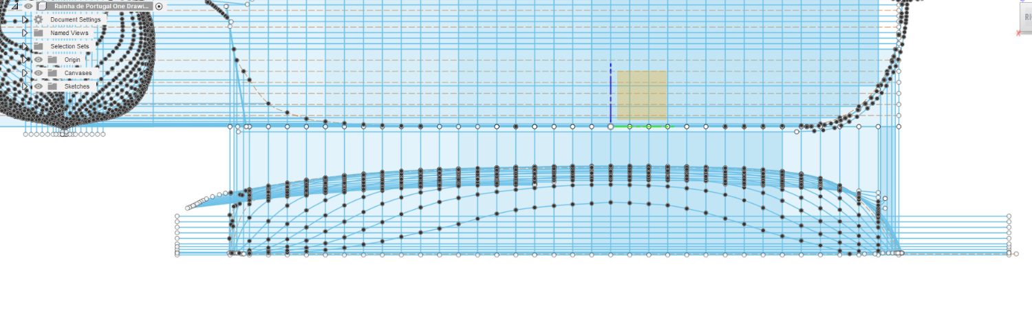
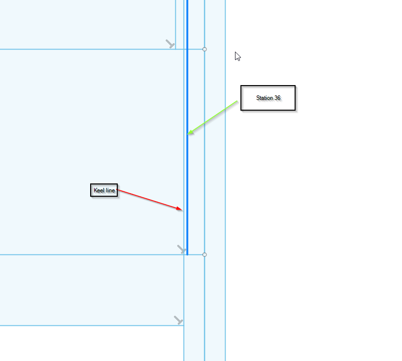
Hi All, Finished the waterlines. I might have made more then I actually need but just wanted to make sure the inward curvature above the wales was captured properly. I'm still not 100% sure about the water lines ends but time will tell I guess... Onward to the buttock lines...

-
mtaylor reacted to a post in a topic:
Nau Rainha de Portugal 1791 by Anguirel - 1:46 - POF - 74 guns
-
Wintergreen reacted to a post in a topic:
Nau Rainha de Portugal 1791 by Anguirel - 1:46 - POF - 74 guns
-
GrandpaPhil reacted to a post in a topic:
Nau Rainha de Portugal 1791 by Anguirel - 1:46 - POF - 74 guns
-
yvesvidal reacted to a post in a topic:
Nau Rainha de Portugal 1791 by Anguirel - 1:46 - POF - 74 guns
-
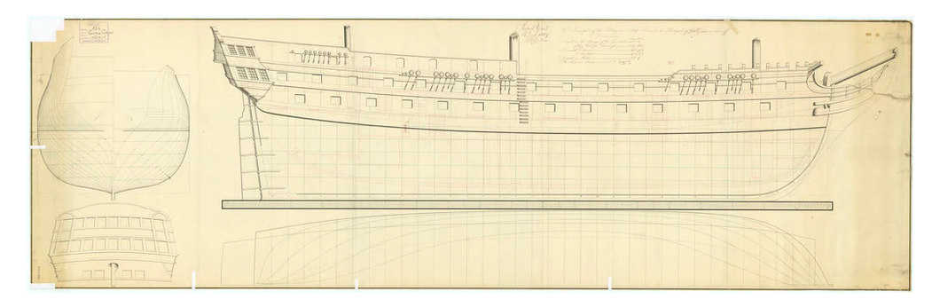
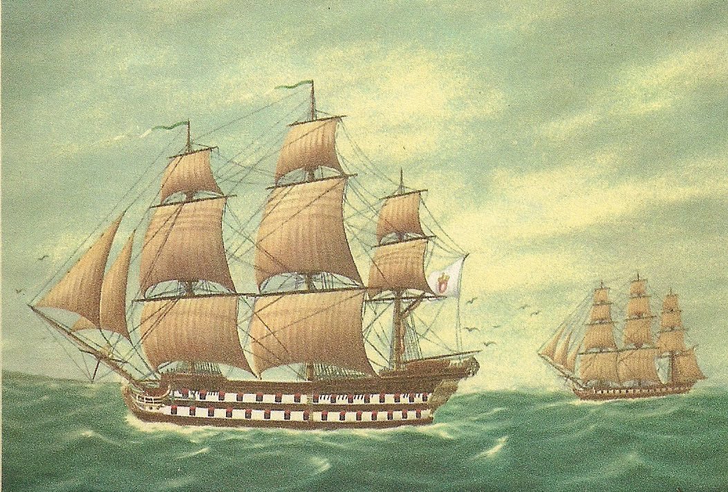
Thanks for your answer Wintergreen, I will try following what you said. Here's a screenshot of the plans: (https://prints.rmg.co.uk/products/rainha-de-portugal-circa-1791-alternative-spelling-rainho-de-portugal-j3203?_pos=1&_sid=ba49b24c4&_ss=r) She was built in Lisbon's dockyards, lunched in 1791. Between 1798 and 1807 she has part of the Squadron of the Strait (Esquadra do Estreito) commanded by the Maqui of Nisa. This squadron supported Admiral John Jervis and Admiral Horatio Nelson in the Mediterranean campaign. The squadron main responsibilities was during the blockade of the Island of Malta. Later in 1807, during the first French invasion of Portugal she helped transport the Portuguese Royal Family to Brazil. She stayed in South America until in 1821, returning to Portugal in that year. In 1833 during the Portuguese Civil War she actively participated in the Battle of Cape S. Vincent on the Absolutists side. She was taken by the Liberals returning to active service during the Cartista Government ending up being dismantled in 1851. She had the reputation of having excellent sailing qualities. Nau Rainha de Portugal in the foreground (https://forum.game-labs.net/gallery/album/98-nau-quotrainha-de-portugalquot/) Nau Rainha de Portugal during the Battle of Cape S. Vincent (1833) being taken by the 46 guns (also) Rainha de Portugal (https://pt.wikipedia.org/wiki/Batalha_do_Cabo_de_São_Vicente_(1833)) Nau Rainha de Portugal returning to Lisbon after the Battle of Cape S. Vincent (1833) under the command of Admiral Charles Napier (he was the commander of the Liberal forces) (https://pt.wikipedia.org/wiki/Rainha_de_Portugal_(nau))
-
mtaylor reacted to a post in a topic:
Nau Rainha de Portugal 1791 by Anguirel - 1:46 - POF - 74 guns
-
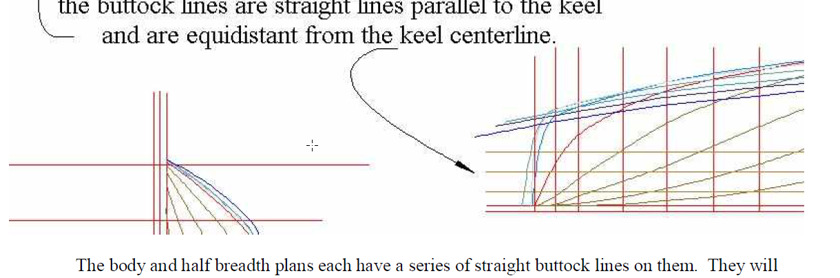
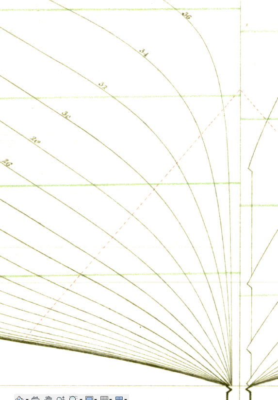
Portugal has a rich maritime history and I always wanted to build a Portuguese ship. The stars kind of aligned when I was reading the Caxton Pictorial Histories series - Nelson against Napoleon. In the chapter about the siege of Malta they talk about the Portuguese squadron that helped in the recapturing of the island. In that chapter there is a drawing of a 74 guns Portuguese ship. That made me think that there has to be some ship plans out there. Apparently not a lot of information survived until today and what is left is not easily available to the general public. It's even more difficult if you are not in country. A few weeks after reaching a dead-end on my research and I was starting to look at other English ships I stumble upon the plans of the Rainha de Portugal at the Greenwich Maritime Museum website. Apparently when she was helping in the Mediterranean campaign she was sent to Portsmouth for refitting. When there, she was surveyed and a plan was made. Armed with the plans and the Drafting Ship Plans in CAD guide by Wayne Kempson I embarked on a drafting journey. I traced the plans in to a CAD software and following Wayne Kempson's guide I'm now drawing the water lines for the half breadth plan. In this section I came across a problem I can't be sure of the answer so I am asking for your help. In Wayne Kempson's guide the ends of the water lines end at the keel: But, on my CAD drawing, at the stern some of the station lines projections are "inside" the keel: Looking at the body plan there are several stations that end "inside" the keel, station 20-36 and a, z, x and u. My question is where should the water lines end? At the edge of the keel or at the deepest point of the rabbet? Thanks in advance, Anguirel
-
HI Anguirel: Go to the USPS web site and calculate your shipping costs from my zip 99337. Let me know!
-
How Realistic Can One Make Sails?
Anguirel replied to Julie Mo's topic in Masting, rigging and sails
Hi All, I read this thread with great interest and it answered all my questions except one. In all models I’ve seen the stichs that simulate the seams of the different panels are vertical straight lines. But in all the images of “real" sails this is a zip-zag stitch. Is this true only in modern sail making? Would it be wrong to use a zig-zag stitch on the sails? -
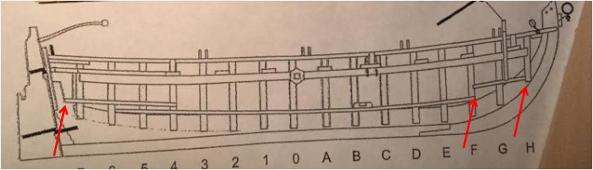
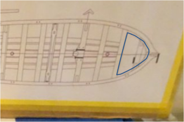
Hi Chuck, Thanks for the reply and if I may another question. I'm installing the floors and found some differences between the instructions and the plans. From the plans the bow floor should start at the base of the H frame so there should be a notch for the keelson (keel?) and it should be round and there is a space of 1/16 between the floor and the footwalings. For the stern floor it should start right next to the sternpost. on your build log the bow floor is round but not notched in the front and it looks like it's too high. On other logs some are notched in the front but are not round and all too high. Also all the logs I've seen the stern floor always starts at the frame number 7, not the sternpost. I'm I reading the planes wrong? Hugo
-
Hi Chuck, First off all great kit, I’m having loads of fun... One question, on your log you say you filled the treenail holes. Can you tell me with what? Hugo
-
Hi All, I’m on the market for a scroll saw. My inclination was for a Excalibur but they are no longer available. My question to you fine gentlemans is: is the new Jet scroll saw (http://www.jettools.com/us/en/new-products-and-offers/new-products/scroll-saw/) worth the extra $500?in the last toon to the Dewalt (http://www.dewalt.com/products/power-tools/saws/scroll-saws/20-variablespeed-scroll-saw/dw788). Christmas is coming so now is the perfect time to convince the Admiral that I need another machine... Thanks in advance
-
Anguirel reacted to a post in a topic:
Steel's Naval Architecture
-
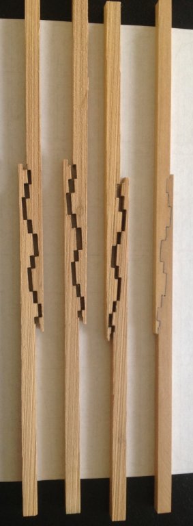
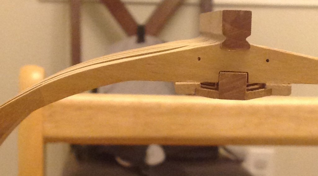
Manage to spend some quality time in the workshop. Planking the inside is done to the level of the lower deck. The guide lines for the treenails is marked, next is drilling the holes and do the treenails. In the meantime I planed to do something different for the deck beams. I did a two timber deck beam with a table and lipped scarph. The one on the right is glued and with the black paper. It came out better then I was expecting for a first try. Now the problem is that the plans are made to use a constant thickness beam which is not the case of this one. Any advice on how to compensate for this? In the case of the lower left and upper right beam arm it must be shorter then on the plans and the other two it must be bigger... I could not find an example of a two timber beam on a model (found several examples of a three timber beams though). As for this one the cuts for the beam arms and carling will "cut" the scarph of the beam. Any advice is welcome... Hugo


-
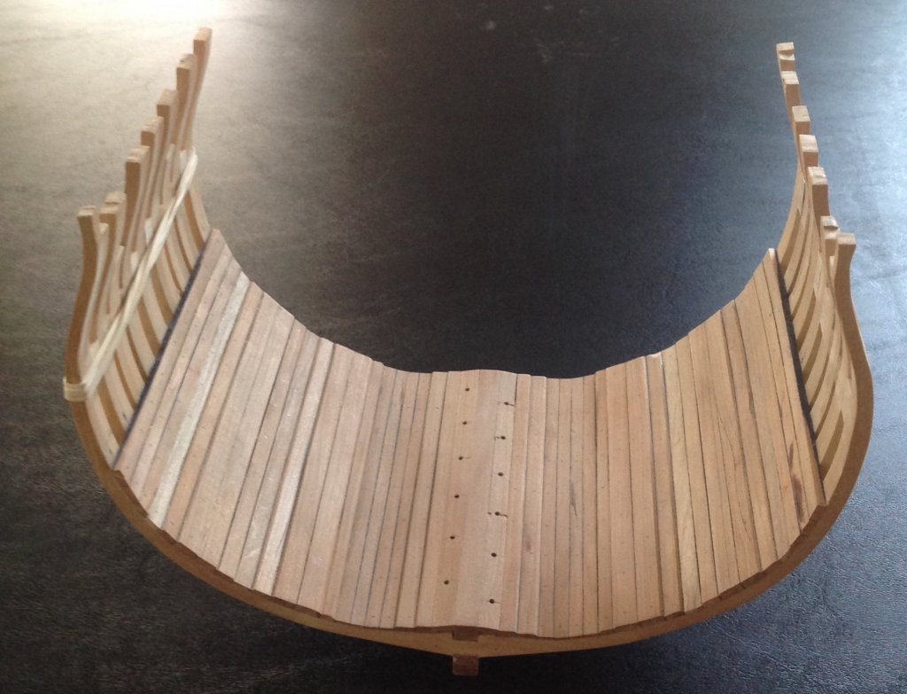
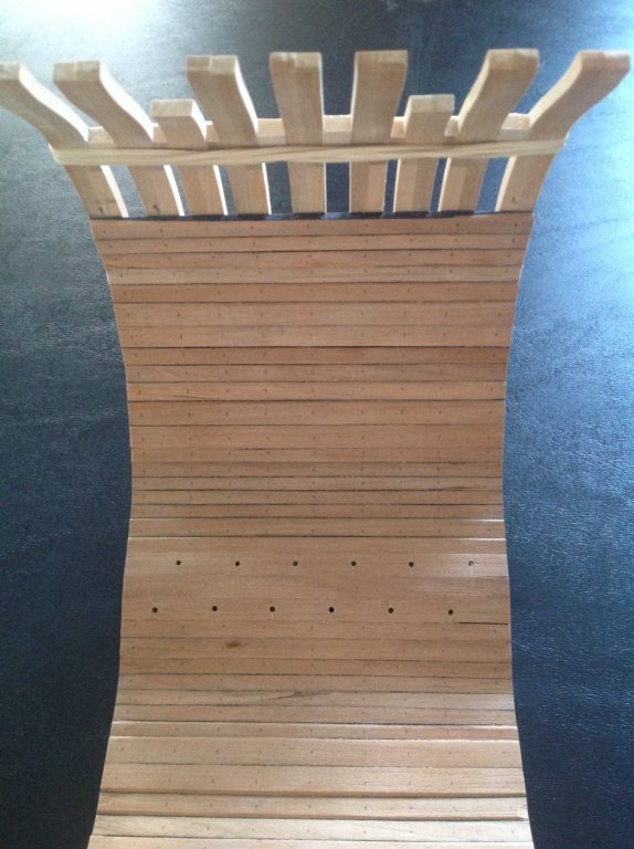
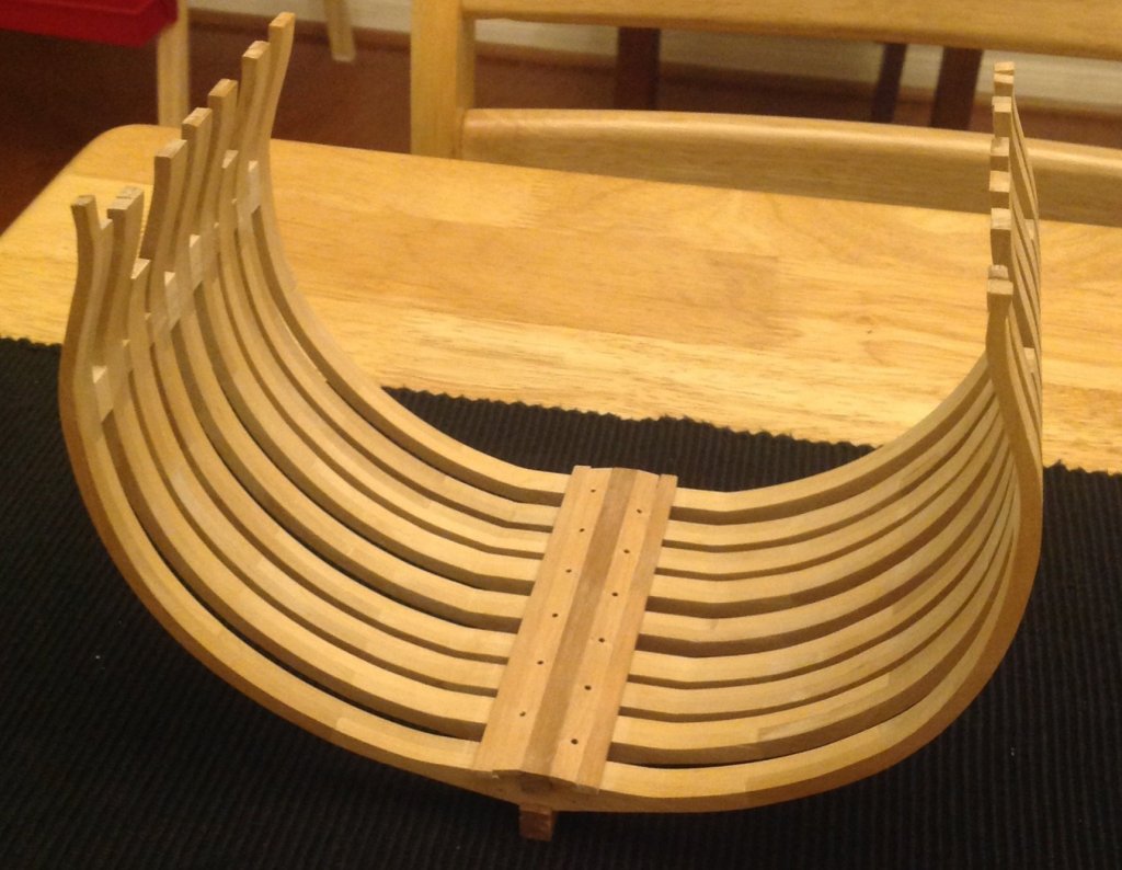
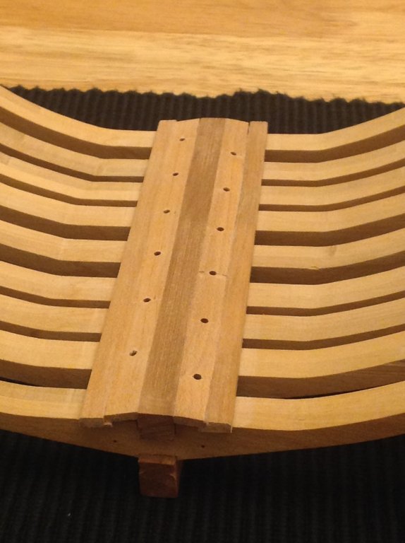
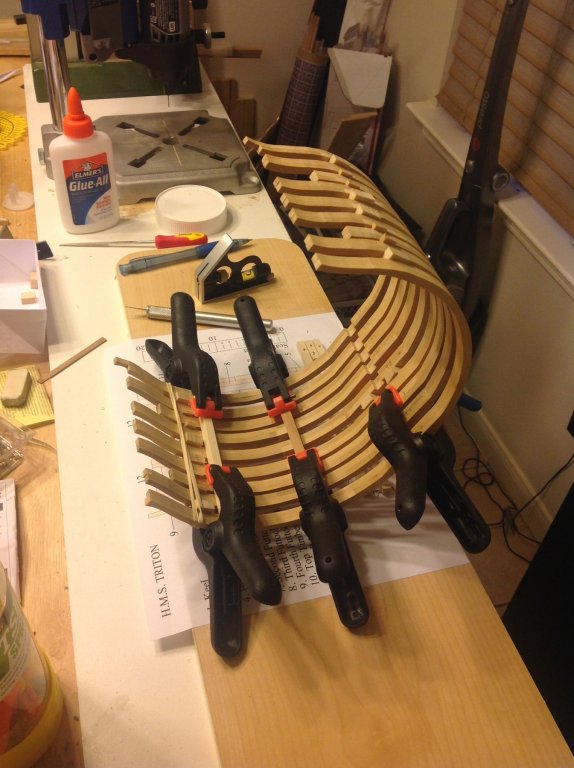
Hi, i haven't been able to spent as much time on the cross section as I like but I manage to do a bit here and there. Sanding took a lot of time and was the only way I could find to give the hull the right shape. Here how she look now... in some places I didn't manage to get a good fit but still learning I guess... Hugo


-
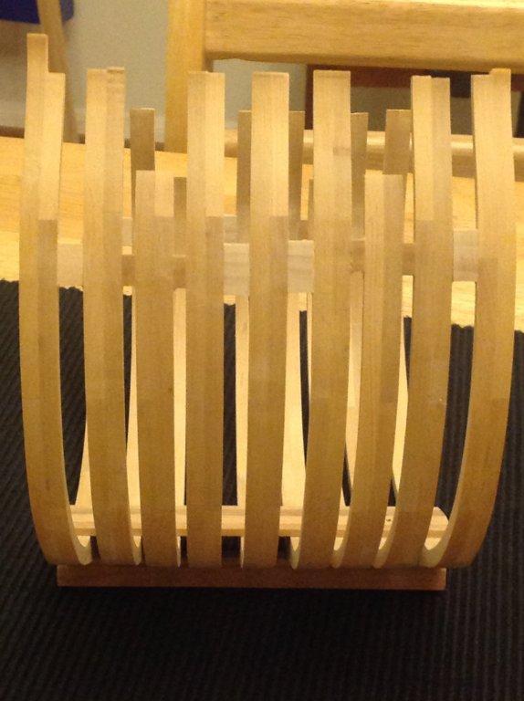
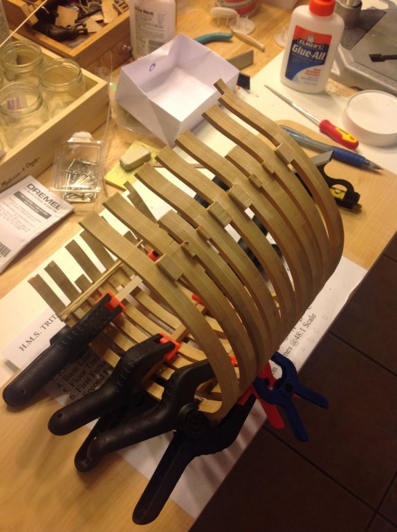
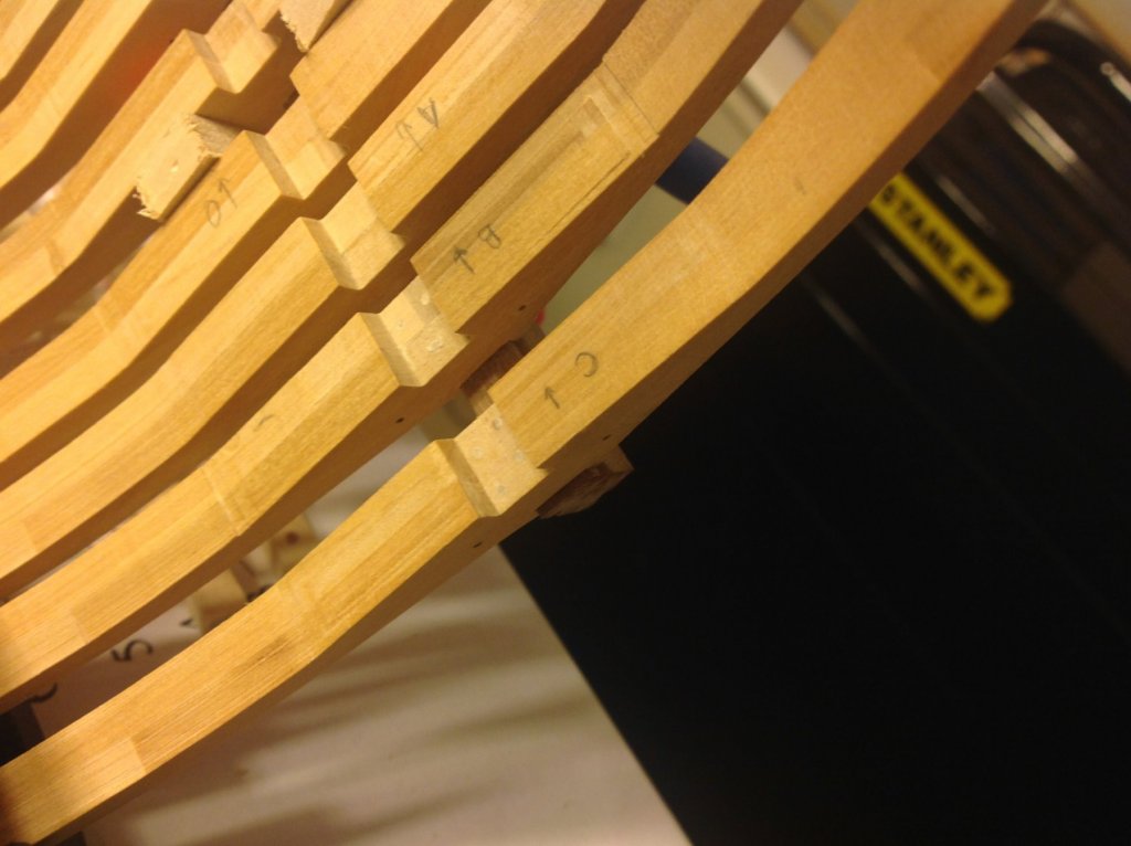
Hi, today reached a point of no return, the frames are in place... with the help of the jig and the spacers it was easier then I was expecting. Still had to redo some of the frames in order to align them properly (that is where I am now...) I played around with patterns of the treenails to fix the frames against the keel... The pattern on frame B seems better but from what I read it was only adopted after 1811 (Sappings System?, can anyone confirm this) and the one on frame C was the one in practice between 1710-1811. Next is the gunport lintels and sills then sanding, lots of sanding... Hugo
-
Finally finished the frames... I have the jig to assemble them ready (I built something similar to ChadB's. one question: is there a proper place for the spacers? I will post some pictures tomorrow
-
Hi kenny, congrats on finishing the cross section. The case looks great...
-
Anguirel reacted to a post in a topic:
H.M.S Triton Cross Section by KennyH78 - FINISHED - 1:48
-
Hi, I asked for a quote for boxwood with the thickness you sent but it was more then I was expecting and because it was my plan from the beginning to plank the all cross session and I want to buy a table saw and a lathe I rather save the money for the tools. So my plan now is to make the frames as they are in the plans and later when I have the tools I will make them "properly" and the decks only, with no planking.
-
Hi all, There is a question that's been bugging me for months now. On the ship's frames were the futtocks buts weatherized? With pitch and/or tar? I know that after the frames where assembled the hull was left exposed to the elements (if done properly for years) so the wood would age and mature. But rain water is different from salt water... I could not find anything in the literature I have access to or the internet. A few weeks ago I had the privilege of visiting the HMS Victory in Portsmouth and on the Orloop deck there are some gaps on the inner hull plucking and the frames are visible. I could find one of the frame's buts and as far as I could see there was no pitch or tar. But the fact that there was direct access to the frames, especially in the Orloop deck makes me think that some kind of weatherization should be made. Can anyone confirm or deny if the frames were weatherized like the deck planks? thanks