UdoK
-
Posts
171 -
Joined
-
Last visited


-
 Obormotov reacted to a post in a topic:
USF Confederacy by UpstateNY - Model Shipways - Scale 1:64
Obormotov reacted to a post in a topic:
USF Confederacy by UpstateNY - Model Shipways - Scale 1:64
-
GrandpaPhil reacted to a post in a topic:
Boston Typhoon by UdoK - Mountfleet Models - 1:32 - RADIO - Steam trawler
-
GrandpaPhil reacted to a post in a topic:
Boston Typhoon by UdoK - Mountfleet Models - 1:32 - RADIO - Steam trawler
-
schooner reacted to a post in a topic:
Boston Typhoon by UdoK - Mountfleet Models - 1:32 - RADIO - Steam trawler
-
schooner reacted to a post in a topic:
Boston Typhoon by UdoK - Mountfleet Models - 1:32 - RADIO - Steam trawler
-
AJohnson reacted to a post in a topic:
Boston Typhoon by UdoK - Mountfleet Models - 1:32 - RADIO - Steam trawler
-
Prowler901 reacted to a post in a topic:
Boston Typhoon by UdoK - Mountfleet Models - 1:32 - RADIO - Steam trawler
-
mtaylor reacted to a post in a topic:
Boston Typhoon by UdoK - Mountfleet Models - 1:32 - RADIO - Steam trawler
-
Paul Le Wol reacted to a post in a topic:
Boston Typhoon by UdoK - Mountfleet Models - 1:32 - RADIO - Steam trawler
-
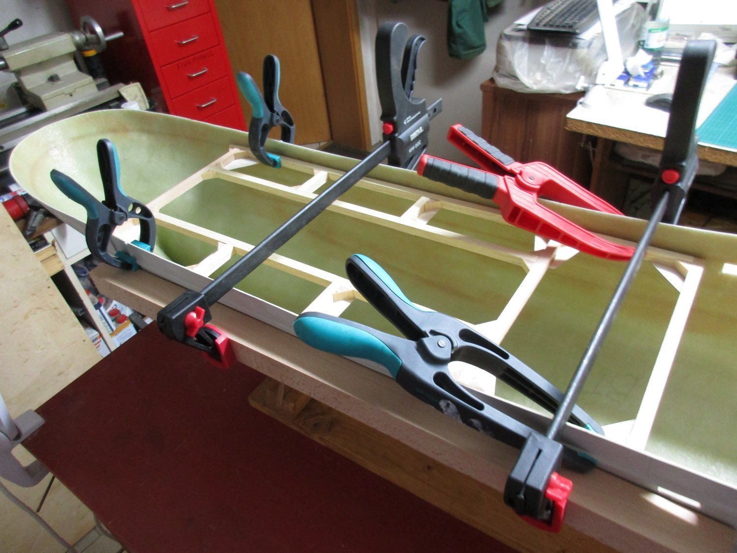
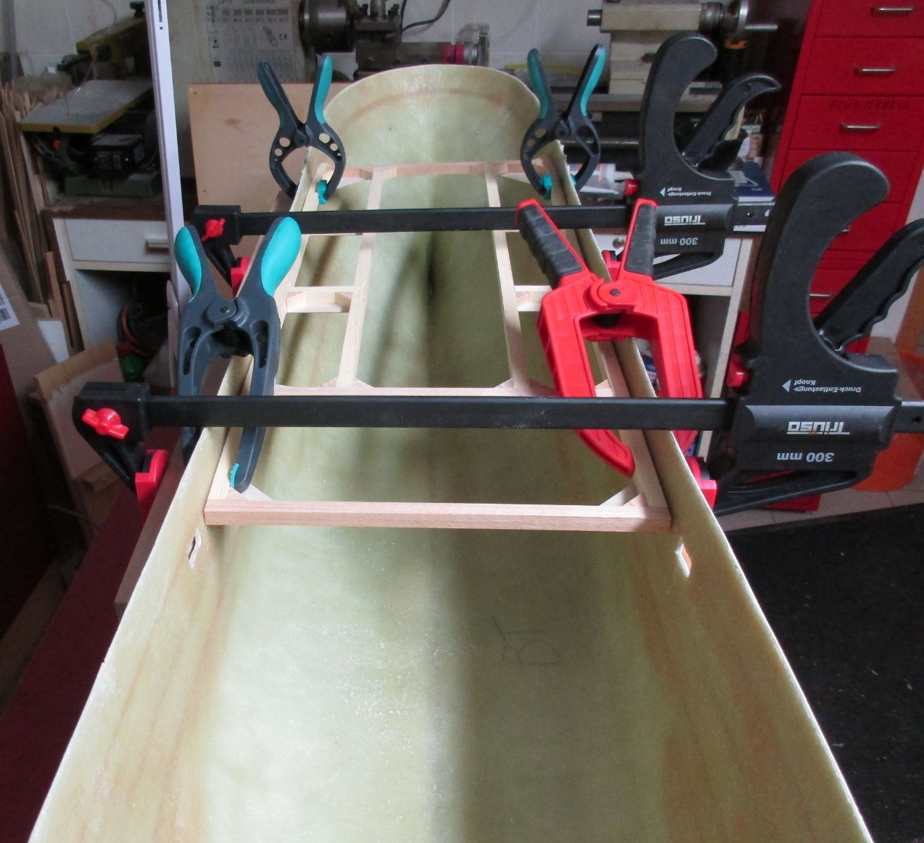
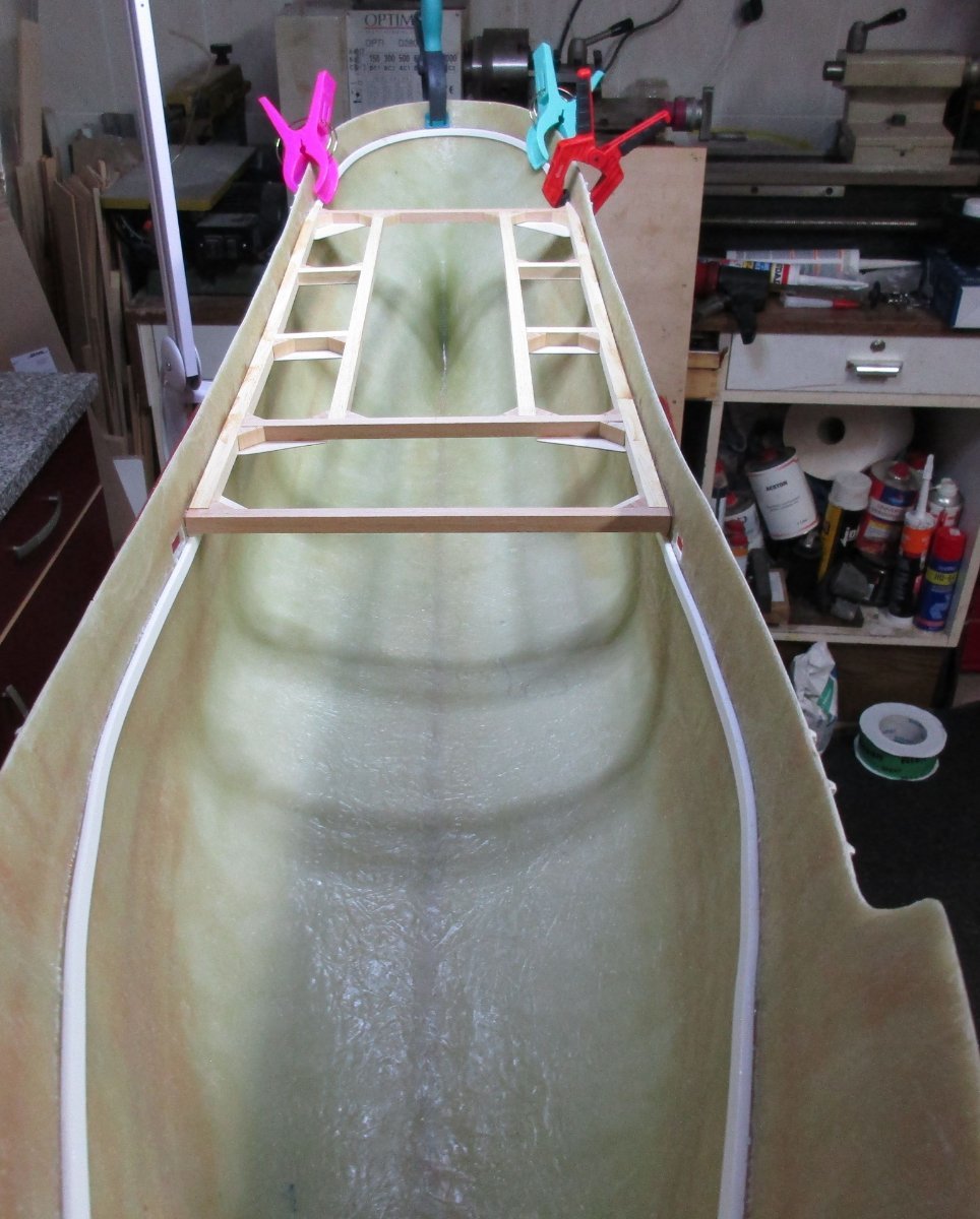
 Blowing the dust off the build log.... The deck subtructure has been constructed and glued to hull in their respective height, measured from the top of the hull according the dimensions taken from the plan. Now that the deck cut-out defines the future access to the inner hull , I will start to determine the position of the built-in parts, drive and accessories.
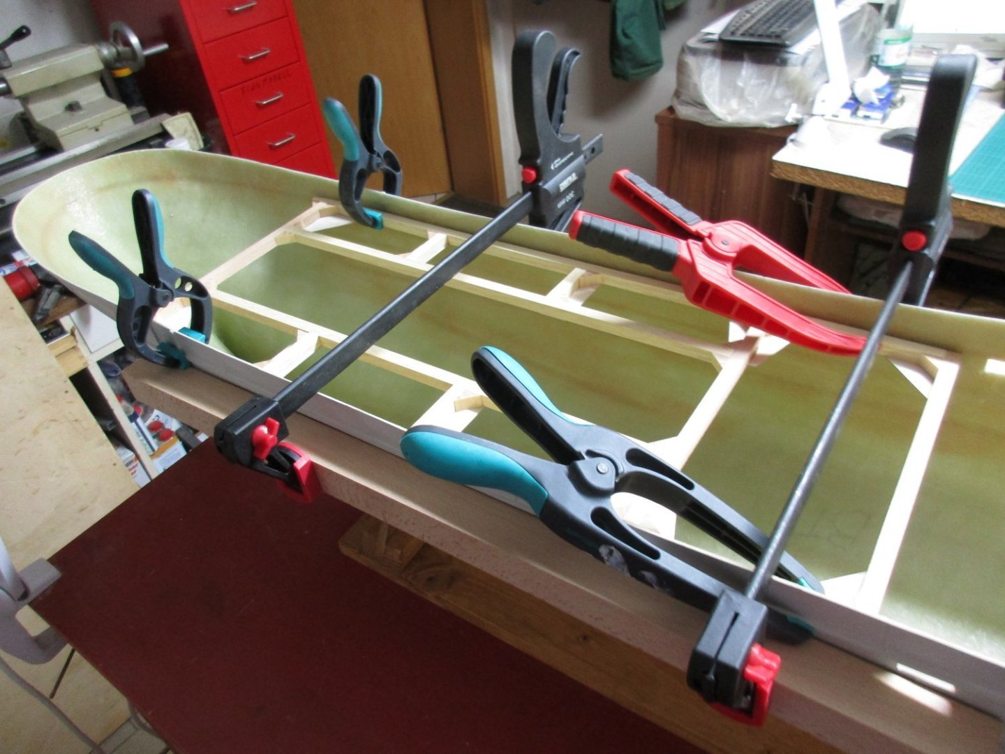


- 4 replies
-
- 6
-
-
- Boston Typhoon
- Mountfleet Models
- (and 1 more)
-
wkm reacted to a post in a topic:
Cutty Sark by Nenad
-
UdoK reacted to a post in a topic:
Messerschmitt Bf-109E-4 by ccoyle - FINISHED - Halinski - 1/33 - CARD
-
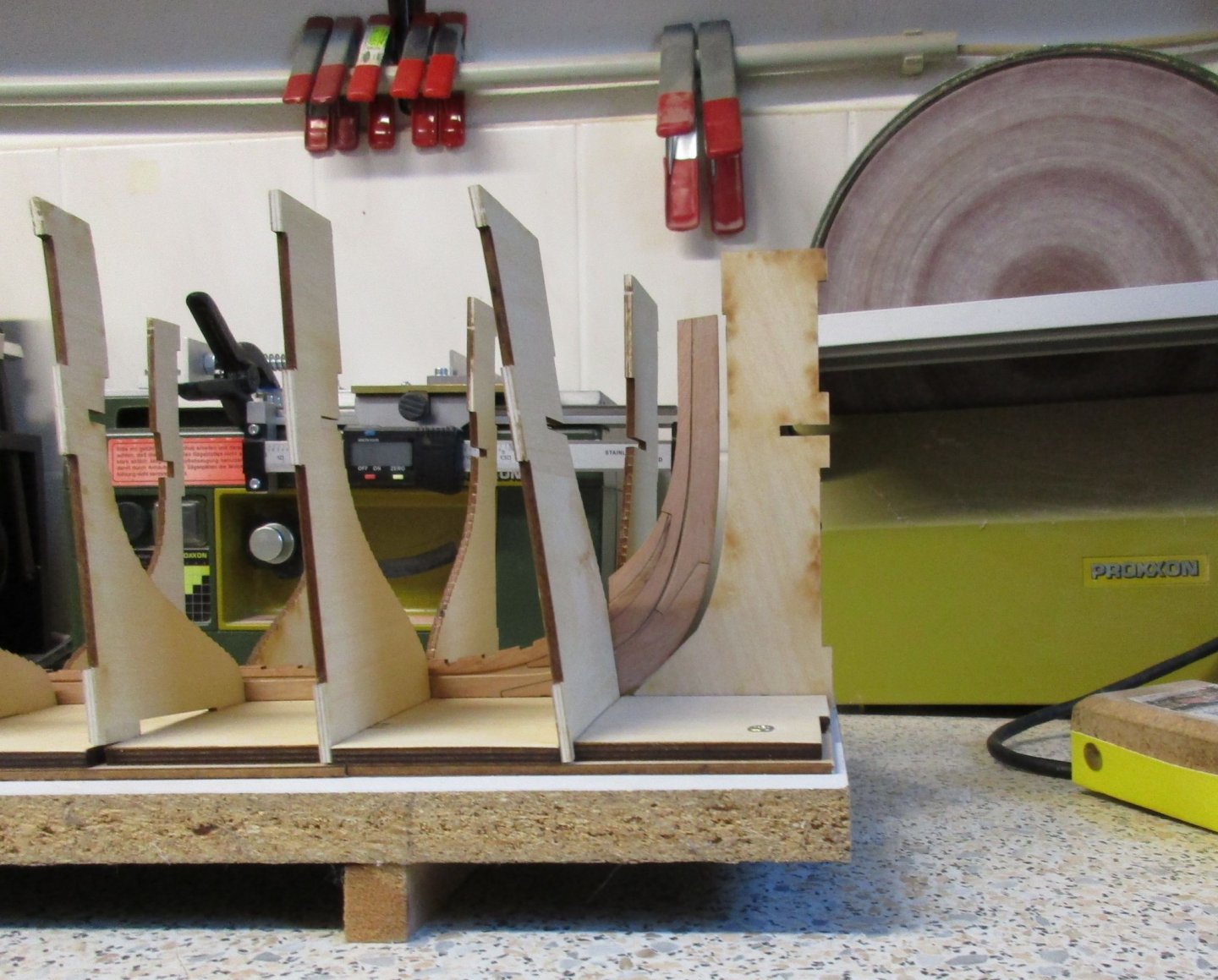
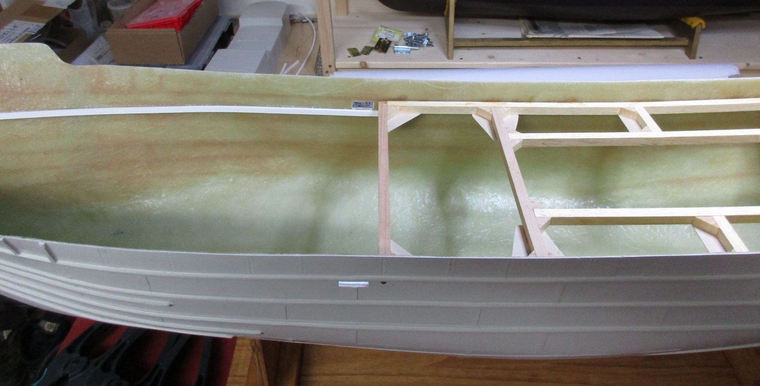
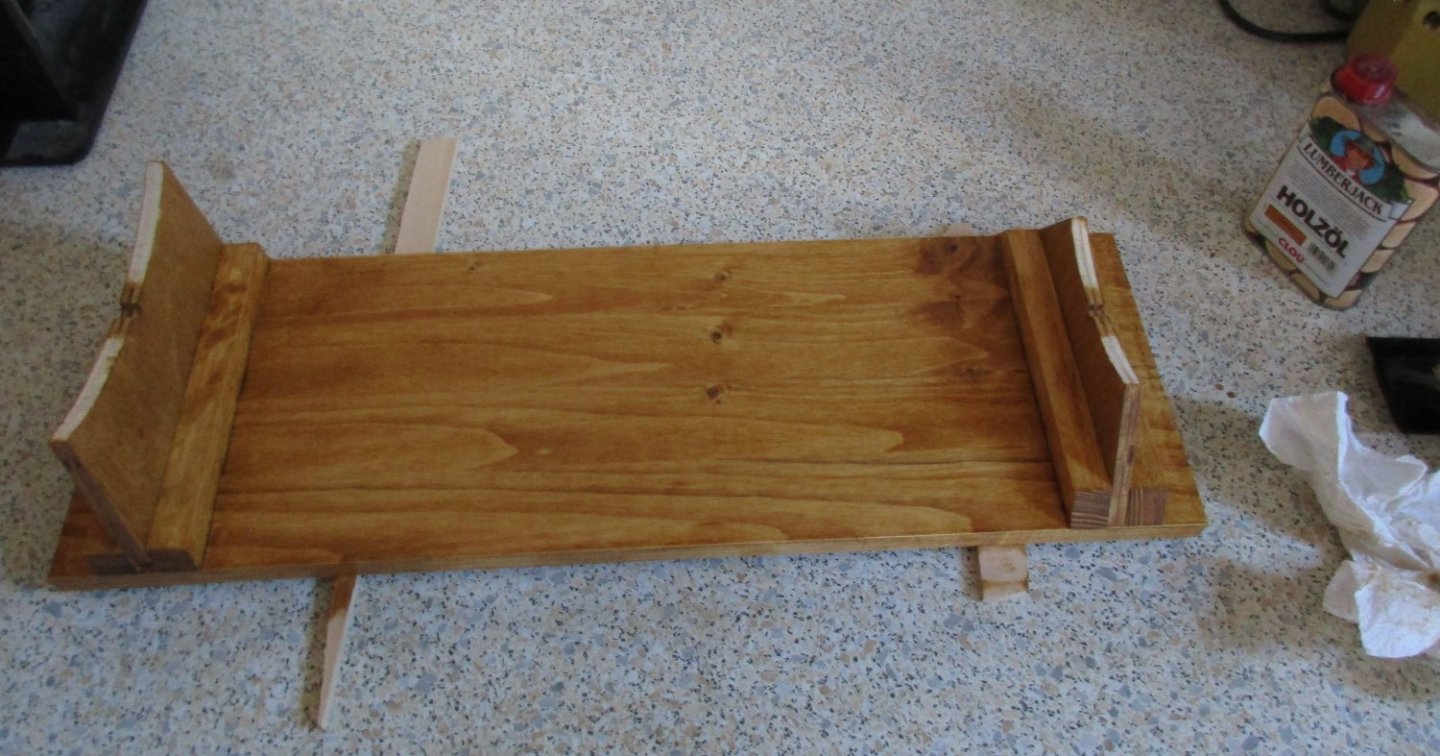
Thank you for your likes, much appreciated! The building cradle is finished, the stands were copied from the plan, cut and glued together with reinforment pieces to a wooden base plate. The hull has been lightly sanded from the outside. Filling in dips was not necessary. some dimple even imitate damage to the hull which I will leave as it is, the ship is supposed to show a lot of wear and tear. Next was to cut out and file the well deck wash ports on both sides. The construction of the deck framing has been started as well, photos to follow...
- 4 replies
-
- 6
-
-
- Boston Typhoon
- Mountfleet Models
- (and 1 more)
-
UdoK reacted to a post in a topic:
Phoenix by Kevin - Panart - 1/84 - Ex Amerigo Vespucci - restarted June 2020
-
UdoK reacted to a post in a topic:
Messerschmitt Bf-109E-4 by ccoyle - FINISHED - Halinski - 1/33 - CARD
-
UdoK reacted to a post in a topic:
P-51 "American Beauty" by Javlin - FINISHED - Trumpeter - 1/32
-
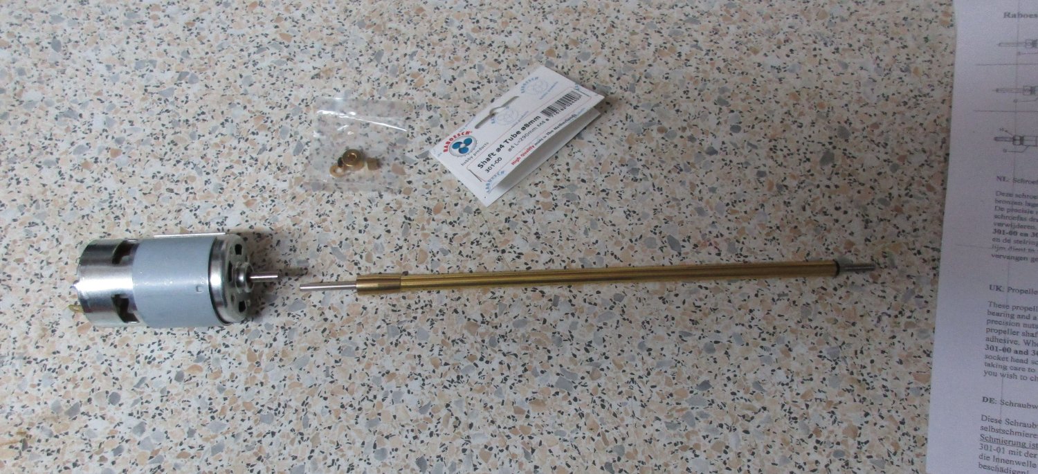
Yes, the drive components arrived yesterday. I will replace the kit supplied shaft with a maintenance-free, bearing-mounted shaft from Raboesch. The engine is an Aeronaut Navy 720, it should be strong enough to power the model.

- 4 replies
-
- 5
-
-
- Boston Typhoon
- Mountfleet Models
- (and 1 more)
-
UdoK reacted to a post in a topic:
Phoenix by Kevin - Panart - 1/84 - Ex Amerigo Vespucci - restarted June 2020
-
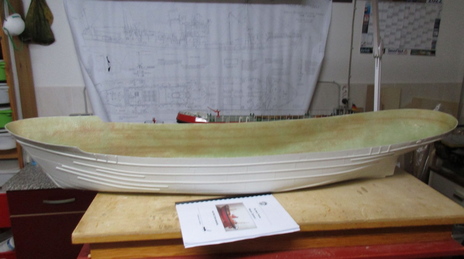
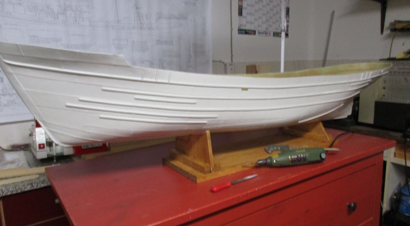
Starting my build of the Boston Typhoon. I'am not showing the kits content since it can be found in my review of the kit earlier here on MSW. Here we go, the moulded Hull has just been arrived on the workshop table ! It has been washed with soap and rinsed with water to remove any residue may remaining from the moulding process. I will start with the usual activities like building the cradle and sanding and filling some rough spots and dips on the outer hull, etc. More to come!

- 4 replies
-
- 8
-
-
- Boston Typhoon
- Mountfleet Models
- (and 1 more)
-
UdoK reacted to a post in a topic:
Enterprize by iosto - FINISHED - CAF - 1/48 scale - adding complete interior
-
CONGRATULATIONS!! A beautiful model, perfect built.
-
UdoK reacted to a post in a topic:
Le Coureur 1776 by captain_hook - CAF - Scale 1:48
-
UdoK reacted to a post in a topic:
HMS Enterprise by Kevin - CAF - 1/48 - August 2020
-
UdoK reacted to a post in a topic:
HMS Enterprise by Kevin - CAF - 1/48 - August 2020
-
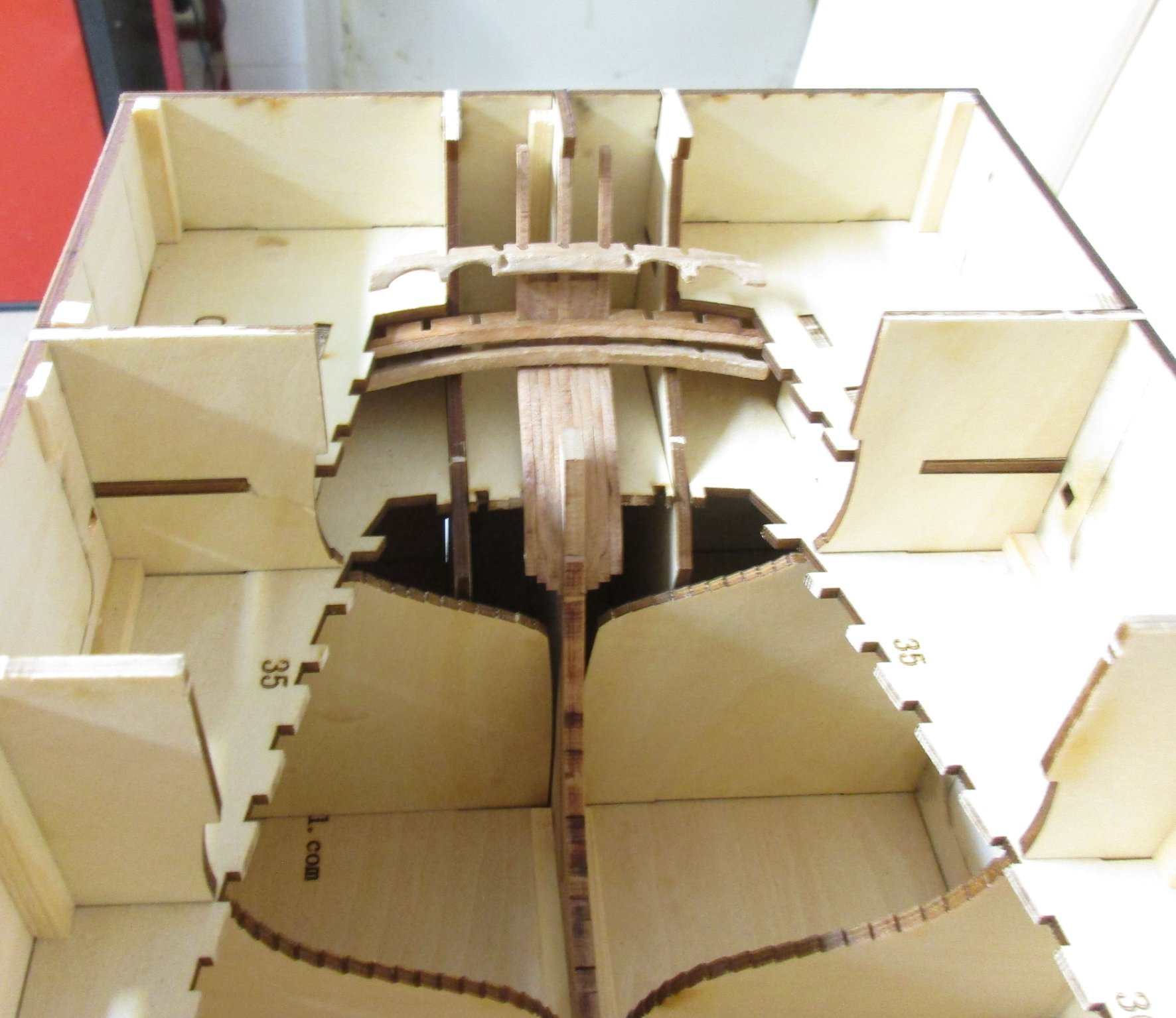
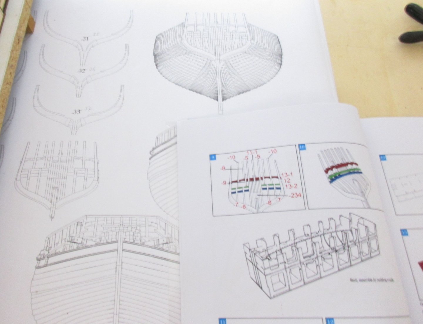
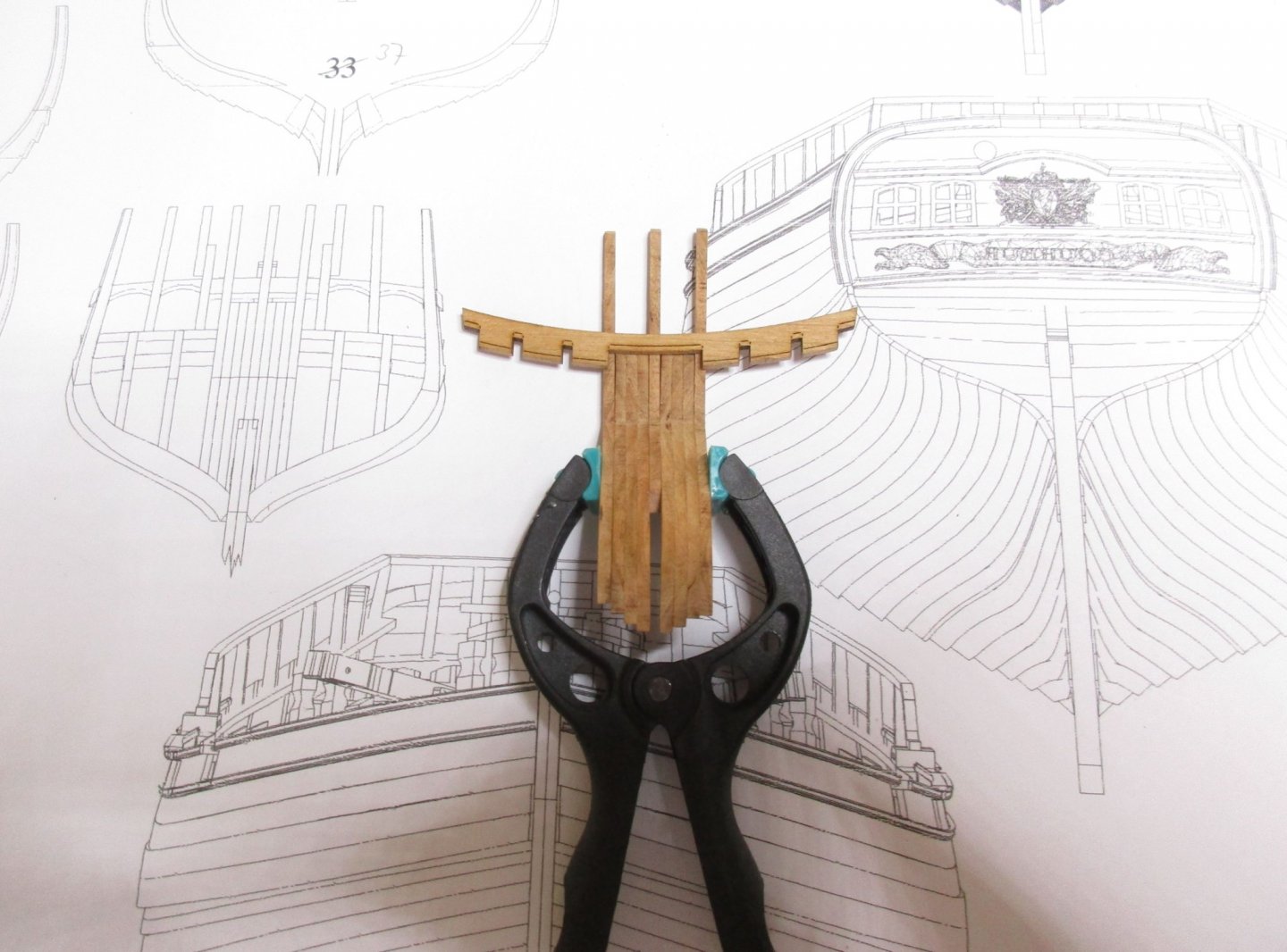
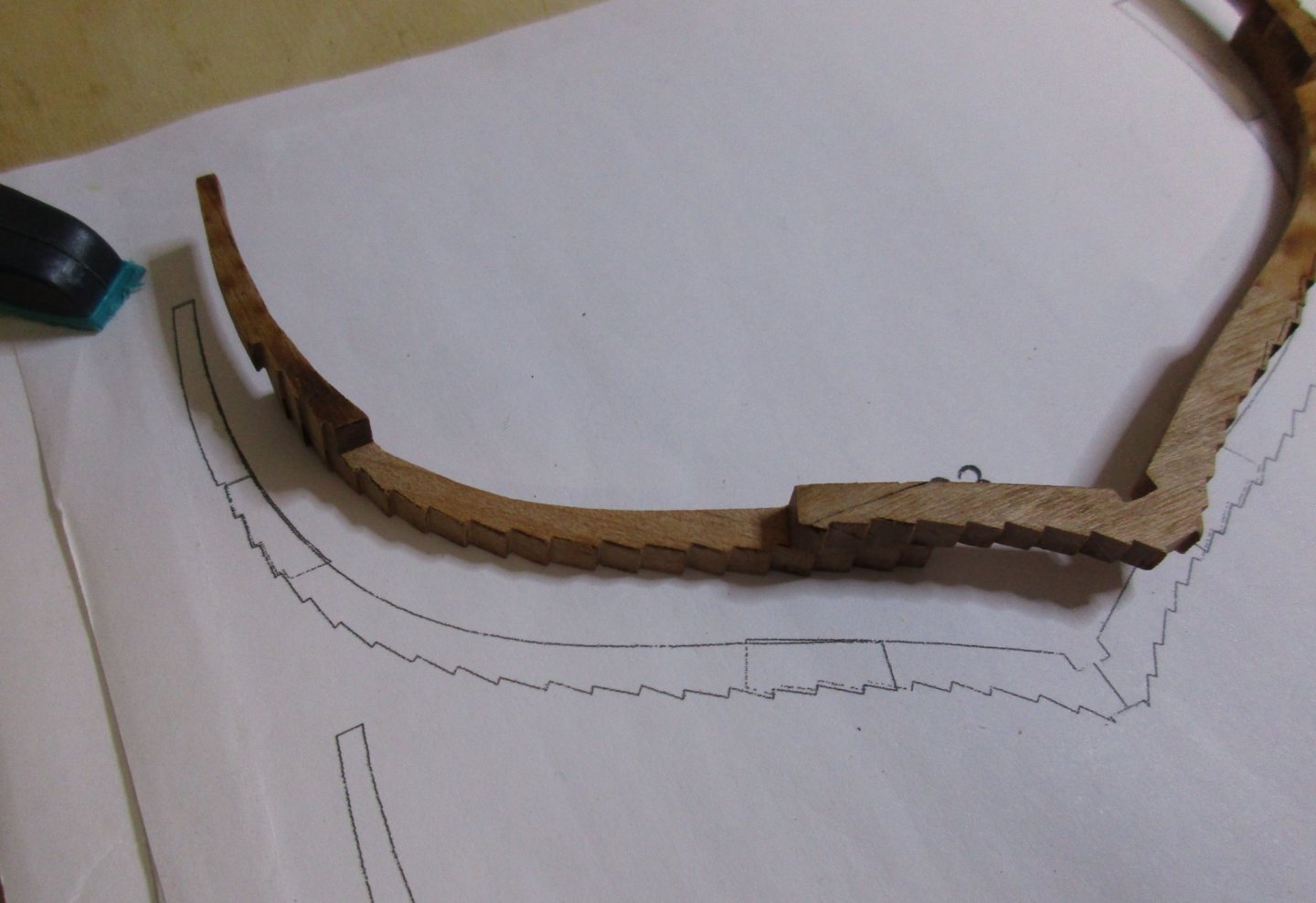
Thanks Cpt. Hook, don't be afraid. After sanding a few frames you will have developed the right feeling for it. Stern construction part I Basically the stern construction is a complex task and requires a lot of thinking ahead, prior to glueing parts together. I have started with the inner stern timber pack, parts 11-1 to 11-5. Due to the parts thickness (slightly oversized) the pack doesn't fit into the respective notches in the transom pieces. After glueing together parts 2-4 I have reduced thickness of both of this packs equally to fit the notches. The transom pieces 12, 13-1 and 13-2 are sanded and dryfitted in the jig together with the center timbers. The laser cut marks on the pieces ease sanding and bevelling the edges a lot. Next task is to construct the side counter timbers in the correct angle. More to follow...

-
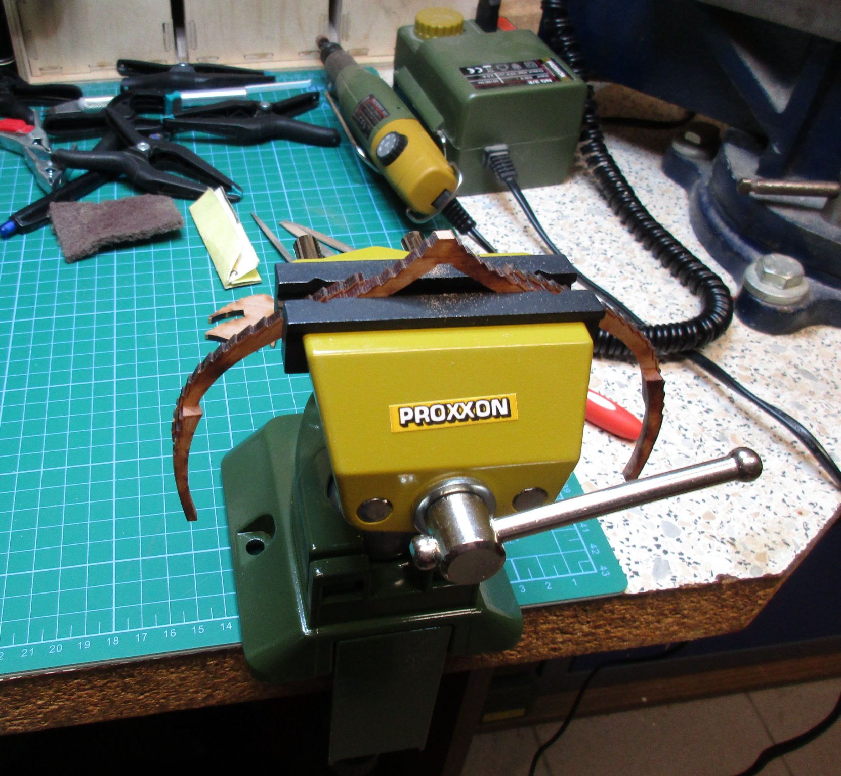
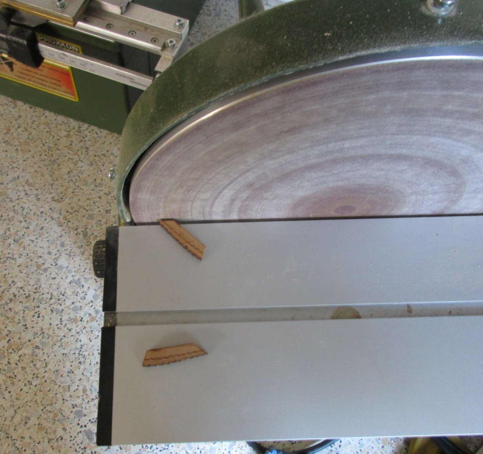
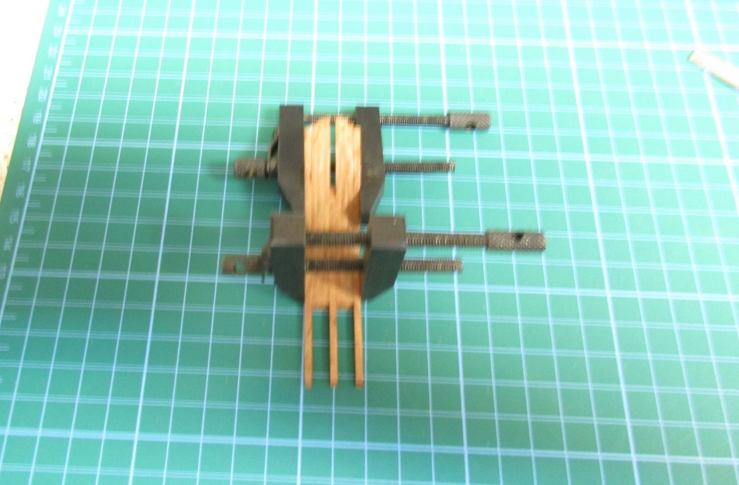
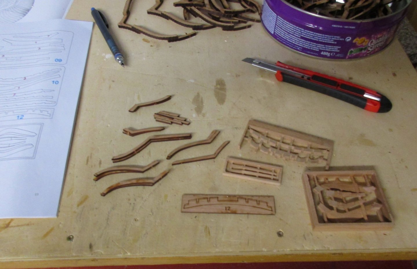
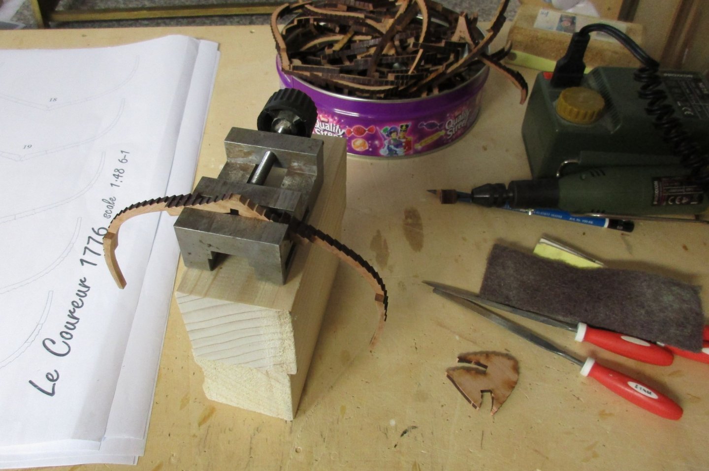
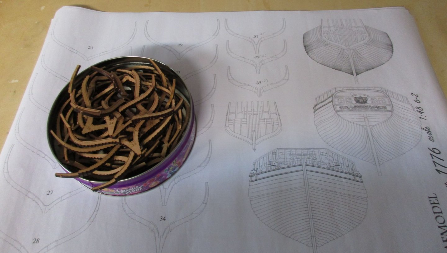
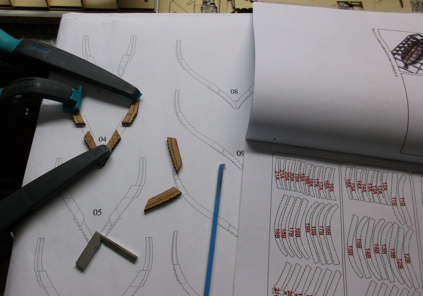
Frame treatment still in progress.... Although I was very careful with the frames it did happen. The small vice dropped off the blocks and the clamped frame broke off, fortunately it was easy to fix. To prevent this from happening again I have orderd the Proxxon FMZ vice, a much more safer way to clamp and work on the frames compared to my construction with blocks. To have a break from sanding frames I have started to work on the complex stern construction. All required parts have been located and cut off from the laser cut panels, ready for clean up. Next is to understand the stern construction and figure out what is the best sequence to puzzle it together.


-
Patience is not a problem for me, rather the monotony of the sanding. therefor I 'am making a slow progress, sanding frame by frame with sufficient breaktimes in order not to loose the entusiasm.
-
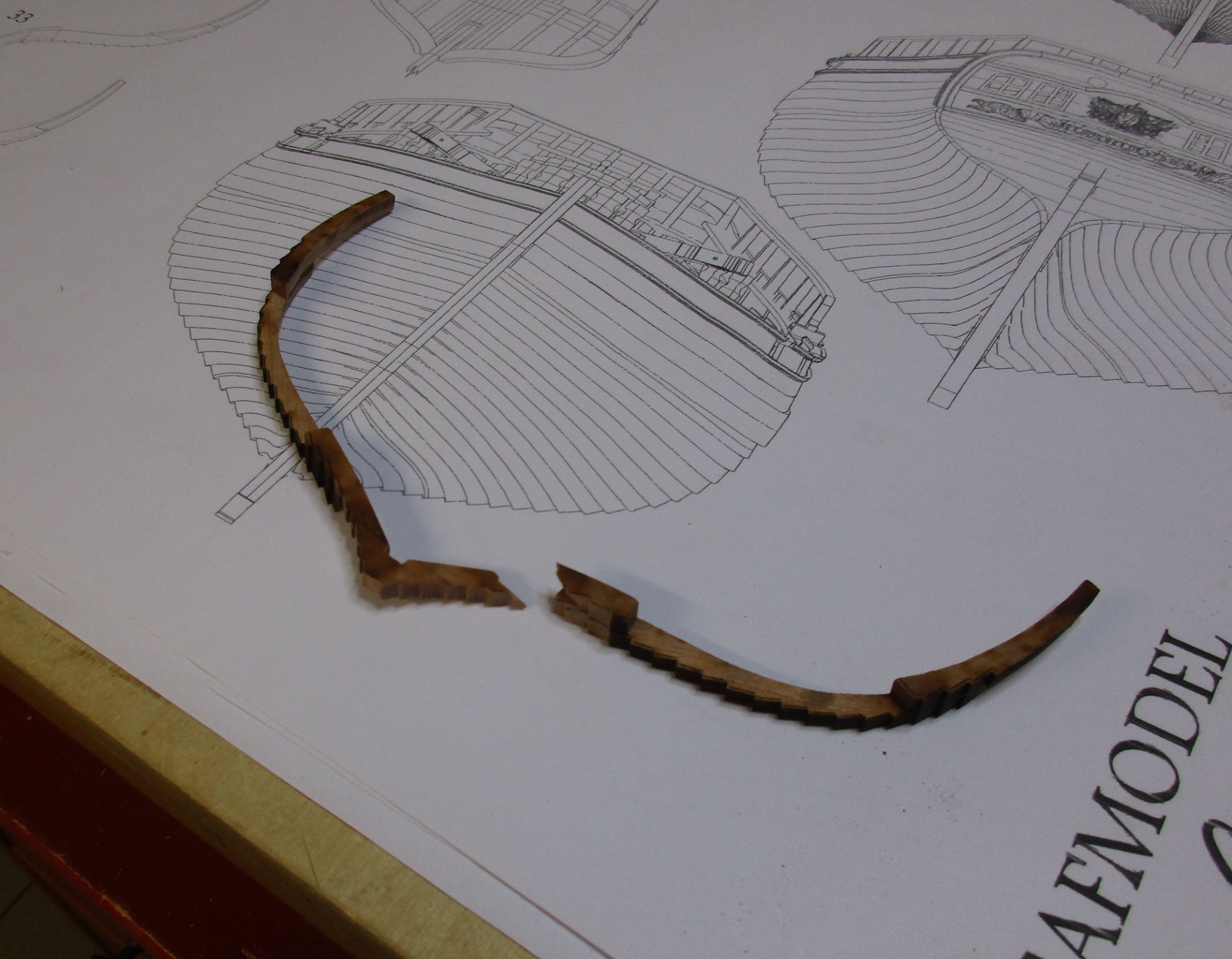
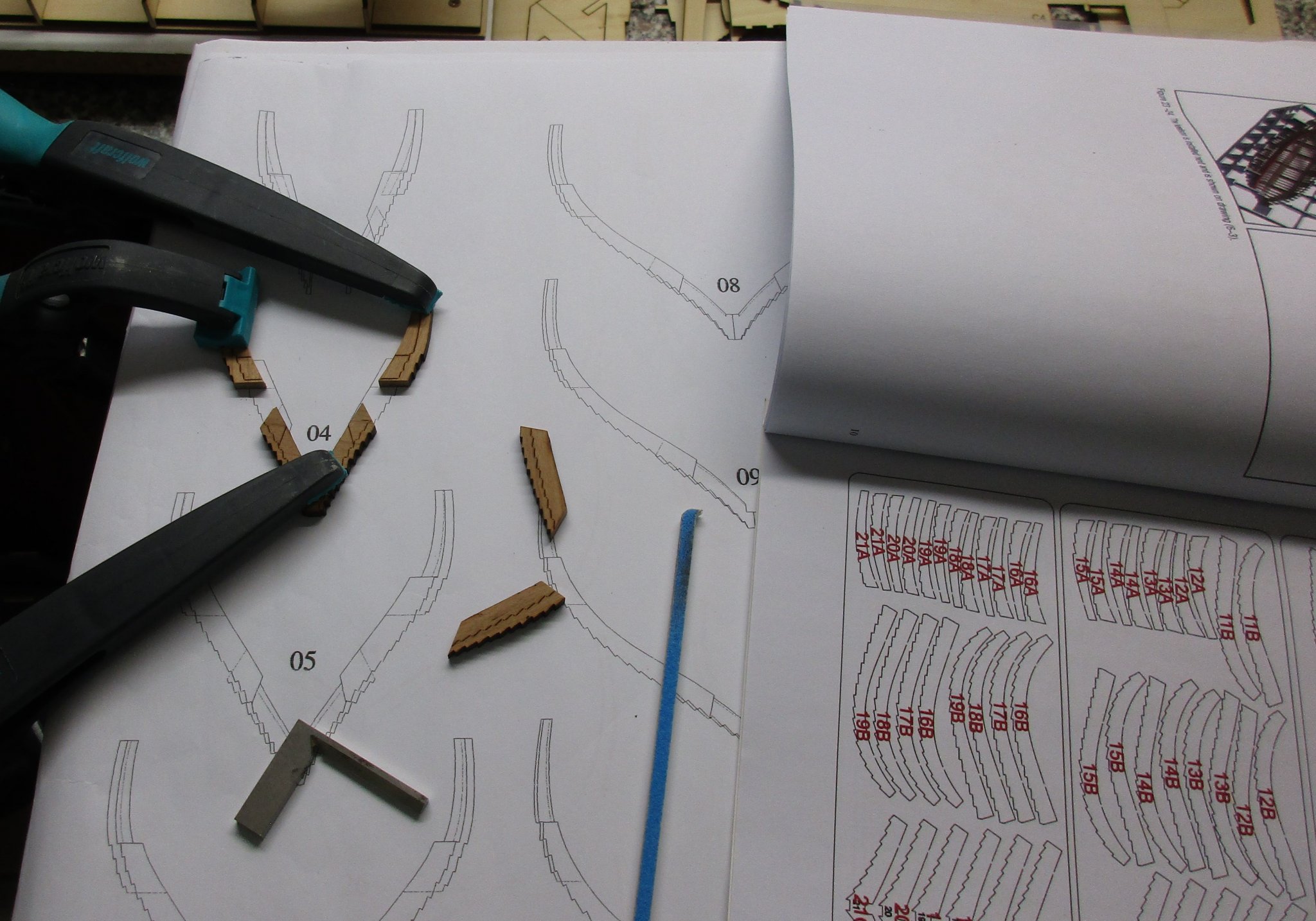
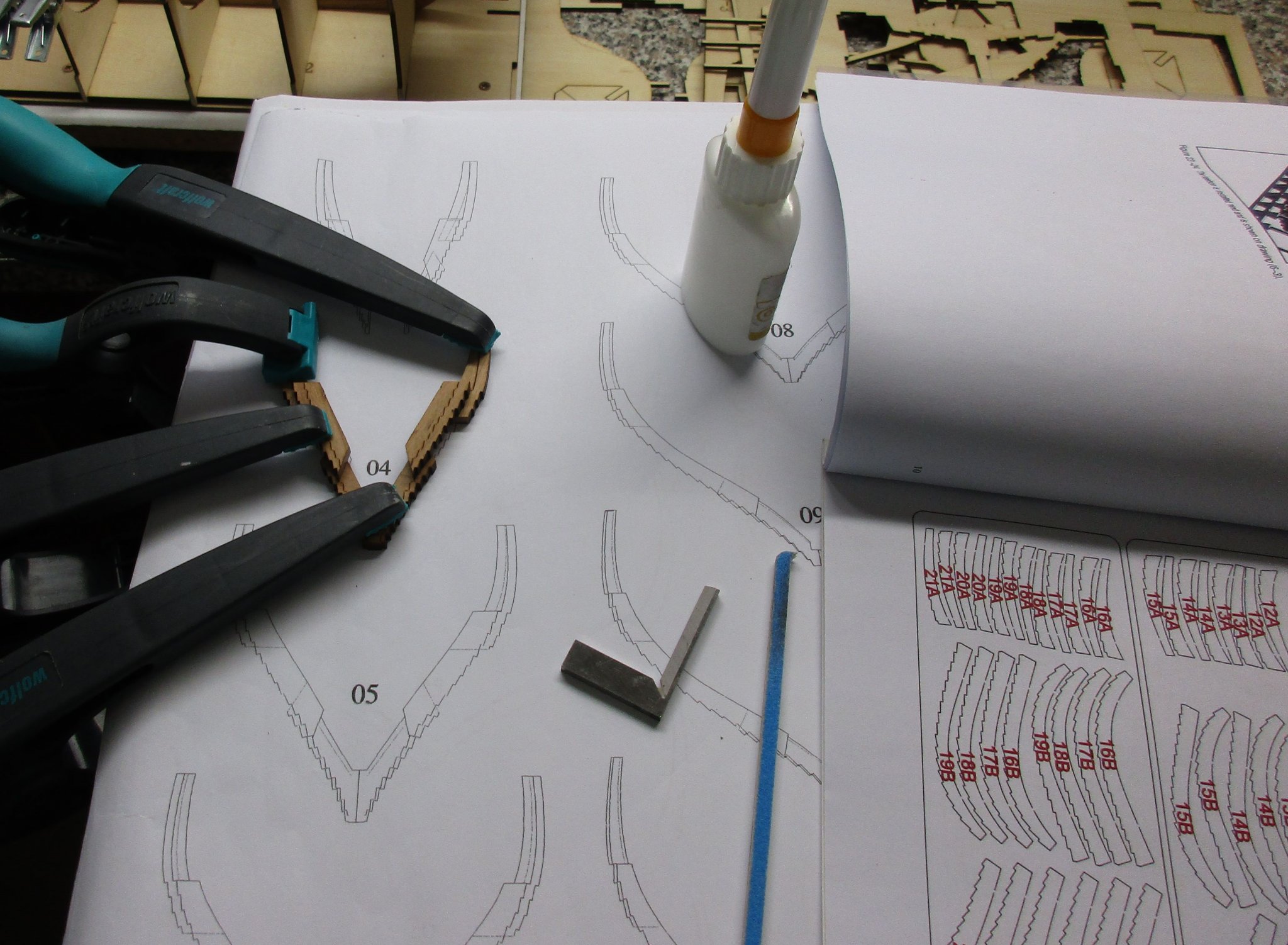
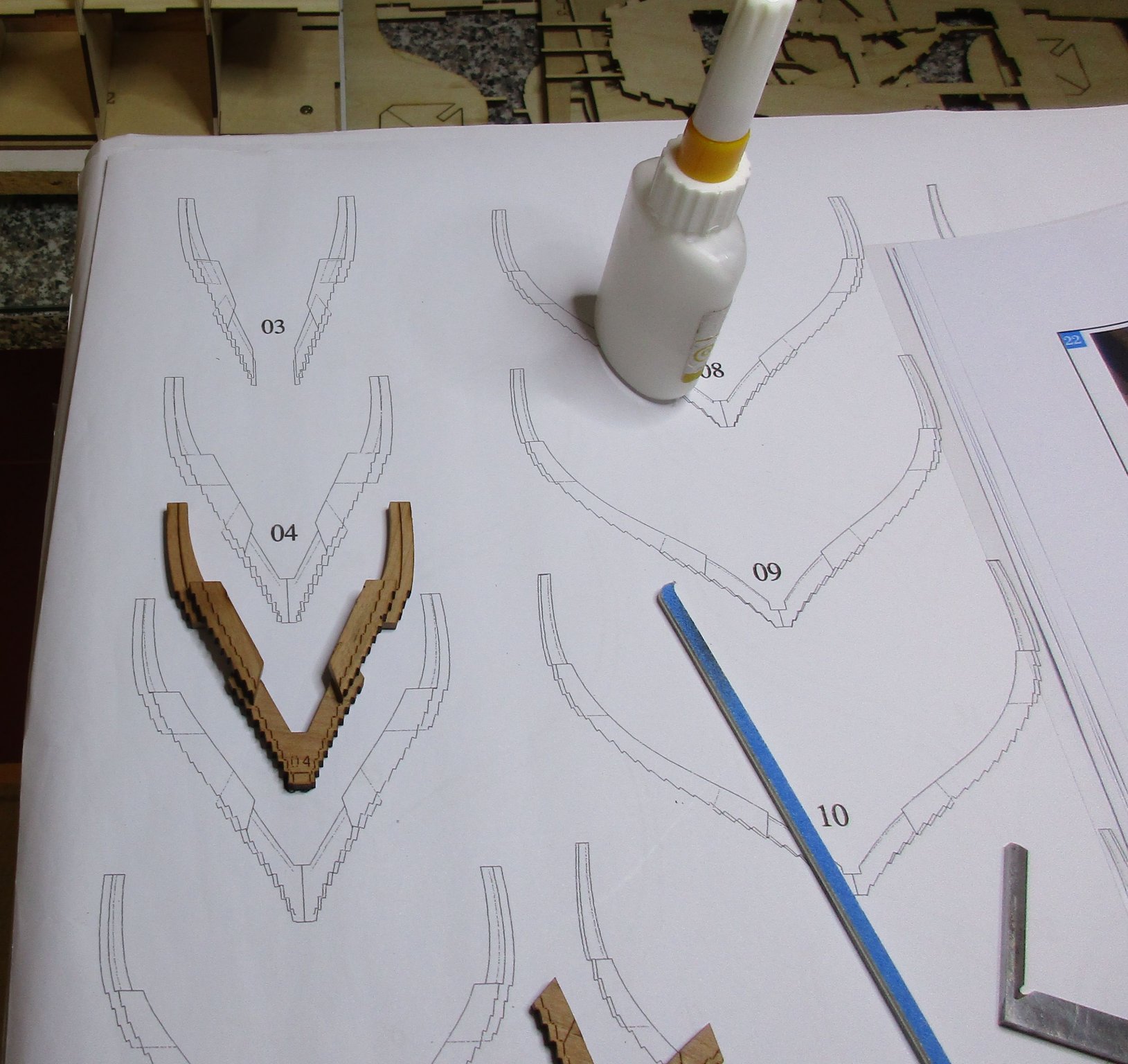
You are right, caution must be taken for sanding and clamping not to break them. I have started at the center frames and work my way up to the stern first. Frame 23 is the first one who requires some slight bevelling. When the frame parts have been aligned and glued together precisely, the laser marks provide a good template for bevelling.
-
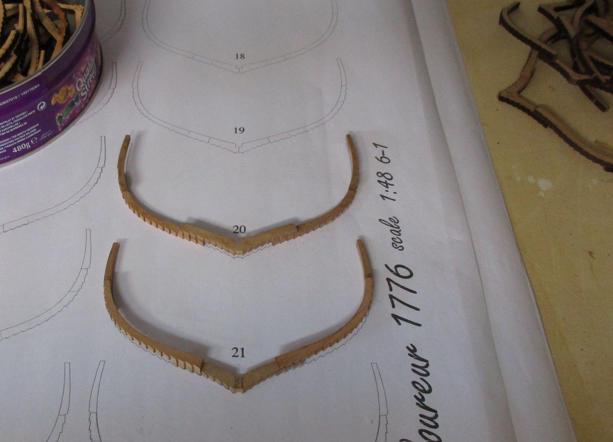
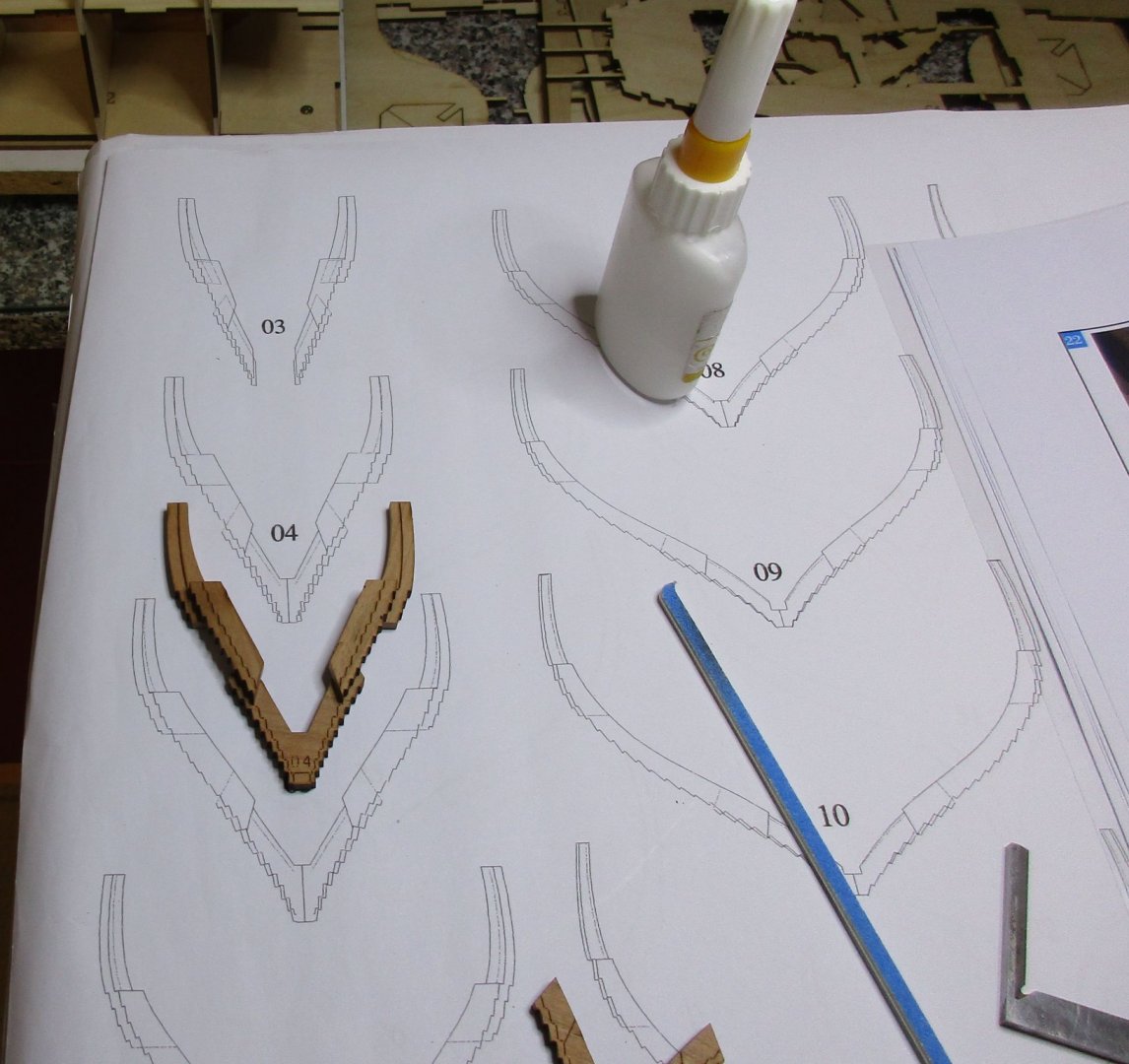
First frames are cleaned up and sanded... I have started with frames 20 and 21 to get a feeling for the numerous steps on the frames as the center frames are not subject to any bevelling. The employment of electric rotating tools is very limited at this stage and can only be used on the frames inner side. All the steps must be sanded with needle files and small sanding sticks. 34 more full frames to go, this will keep me busy for a while

-
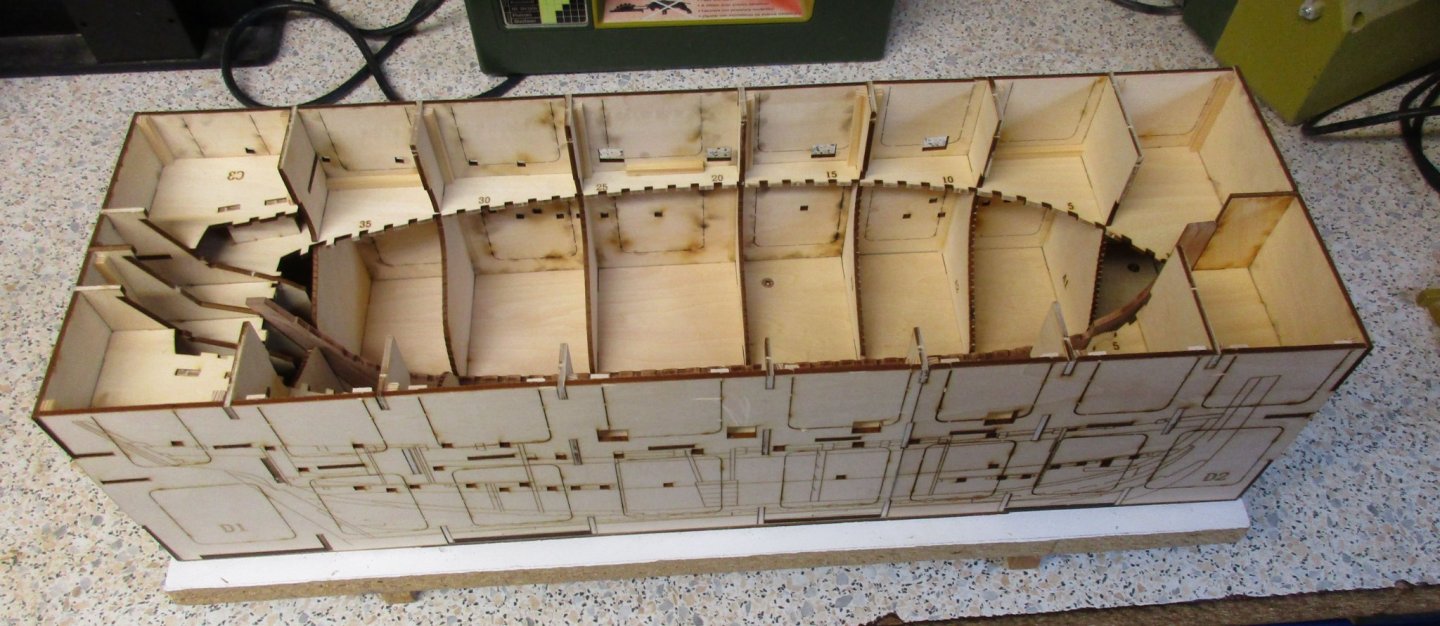
Building cradle completed.... All joints has been brushed up with wood glue, reinforcement pieces are installed on some edges on where I thought it will appropriate to stiffen the parts. As the instruction manual 2 instructs a conversion of the building cradle after the hull planking is completed, I made the top of the building cradle removable from the base plate to ease the modification. Now, since all full frames 4 to 36 are glued up and waiting for sanding and beveling, the real fun starts.

-
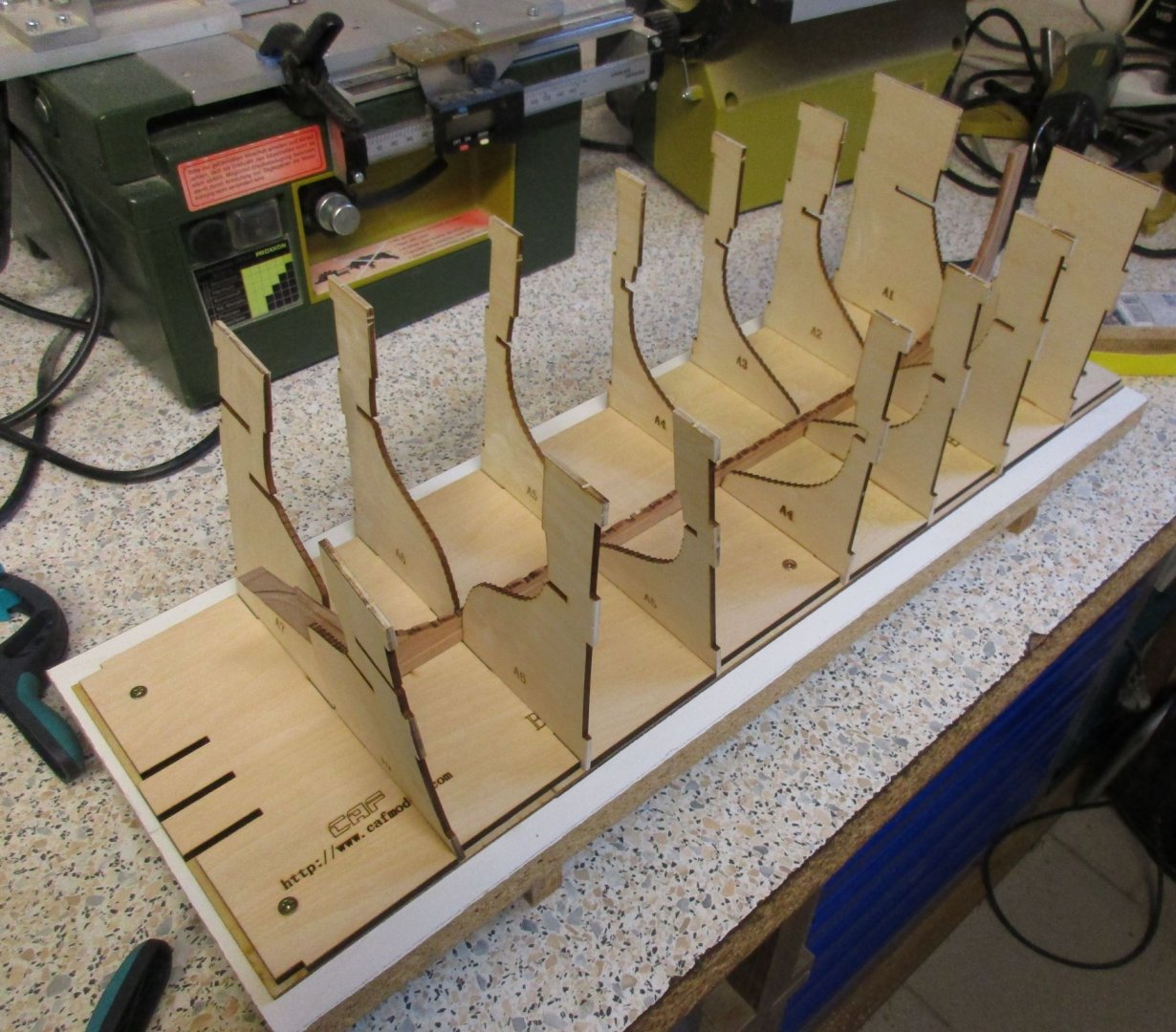
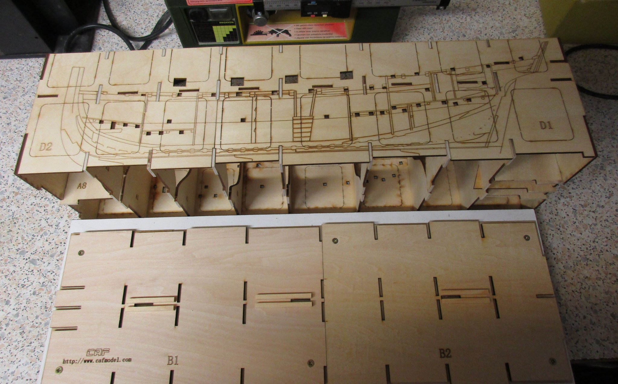
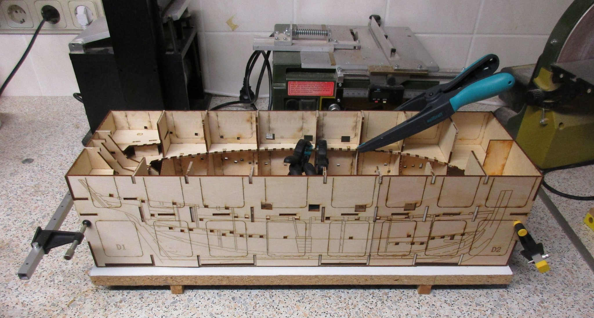
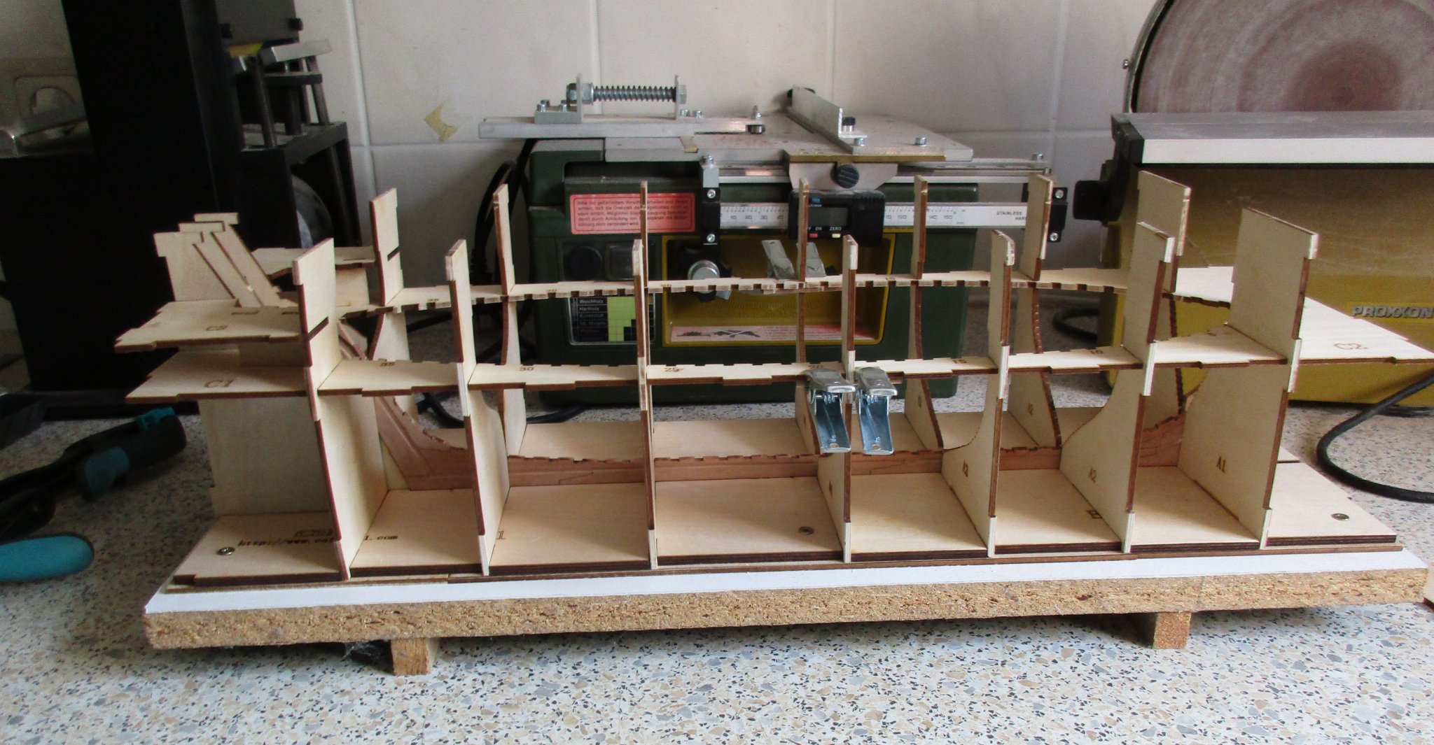
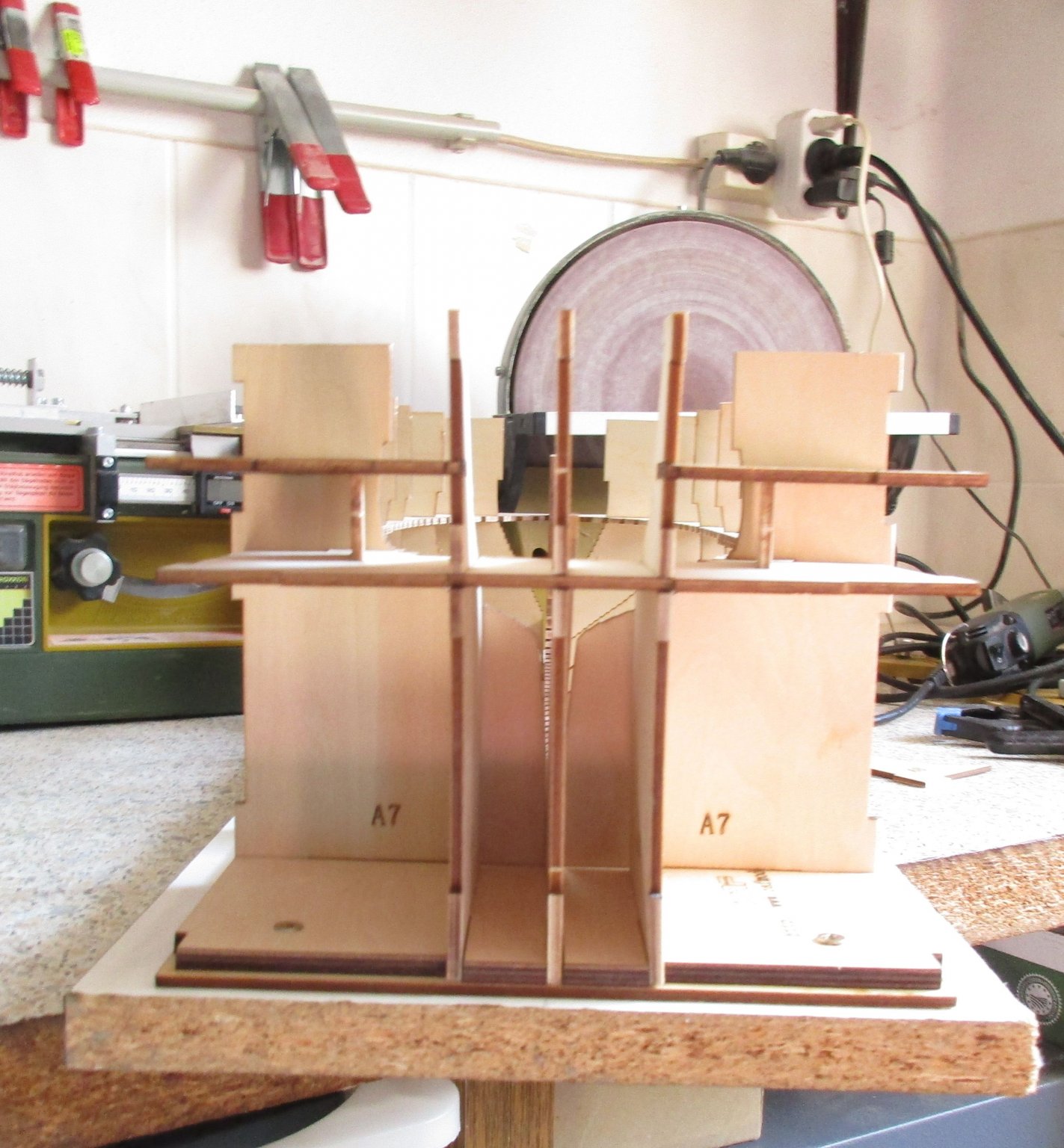
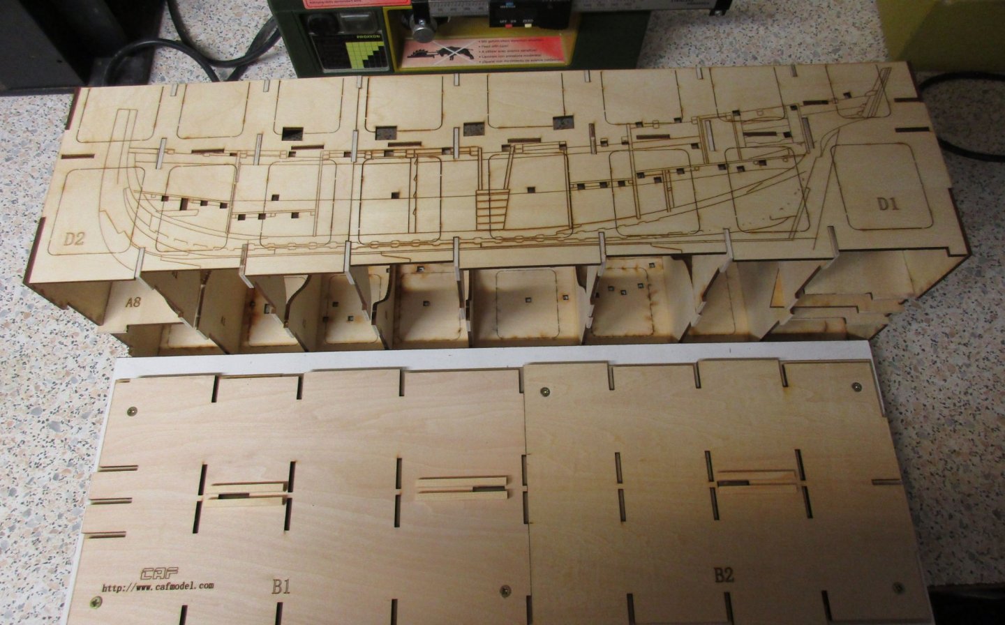
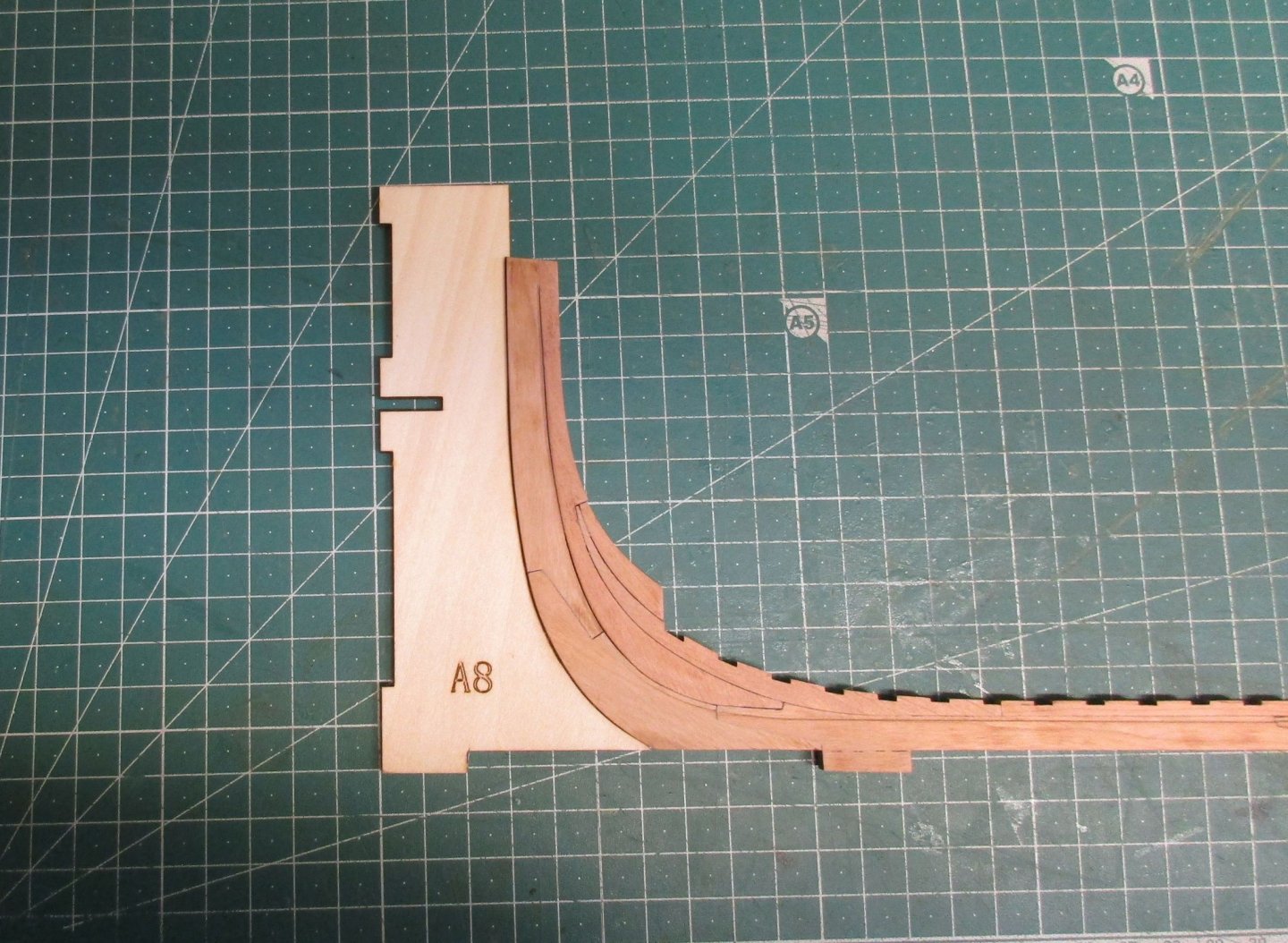
Meanwhile the missing parts E are already arrived, 5 days after sending the message to Tom. Another sign that Tom is really concerned about customer satisfaction.... So, the building cradle has been completed, just dryfitted. The perfection and fit of the lasercut joints is really remarkable. Beside removing some laser char here and there and sanding the curvature on piece A8, no major sanding or adaption were required. The clamps are only in usage because some of the plywood pieces are a bit twisted, but not really an issue. Next is to fix the construction with glue.


-
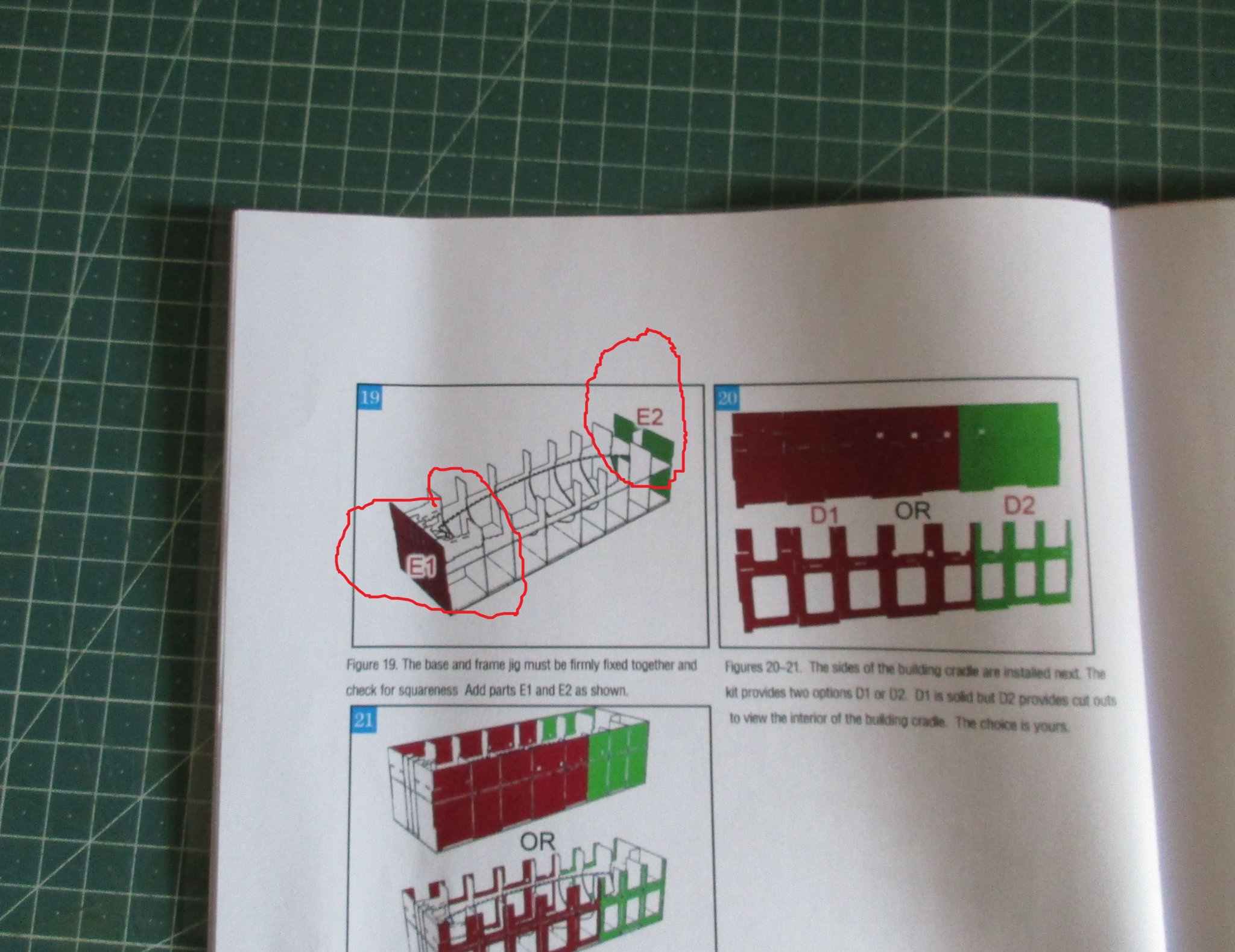
I have send an message to CAFmodel, Tom concerning the missing Parts E1 and E2. He replied right away with the information that he will send out the pieces immediately. That's what I'am calling a outstanding customer service........ The construction of the building cradle will be suspended until arrival of the pieces. Construction of the frames has been started with the first full frame number 4. In the first step of cleaning up and sanding the frames I have used my disc sander to sand the pieces front and end smooth. Afterwards the individual pieces are properly aligned over the drawing and clued together. For sure it will provide a lot of fun to clean up the laser char and sanding all the clinker planking teeth into shape on all the frames.


-
Thanks James, good to hear. I will contact Tom as well.
-
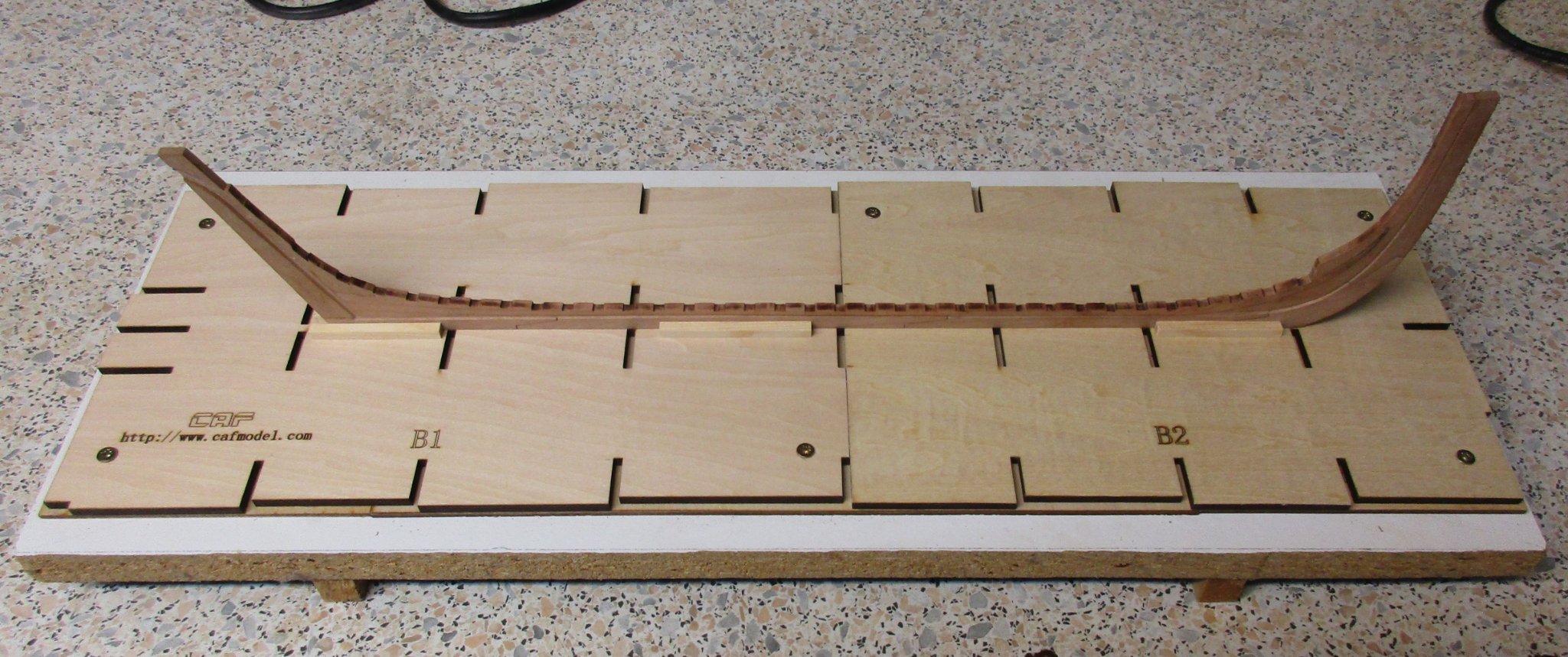
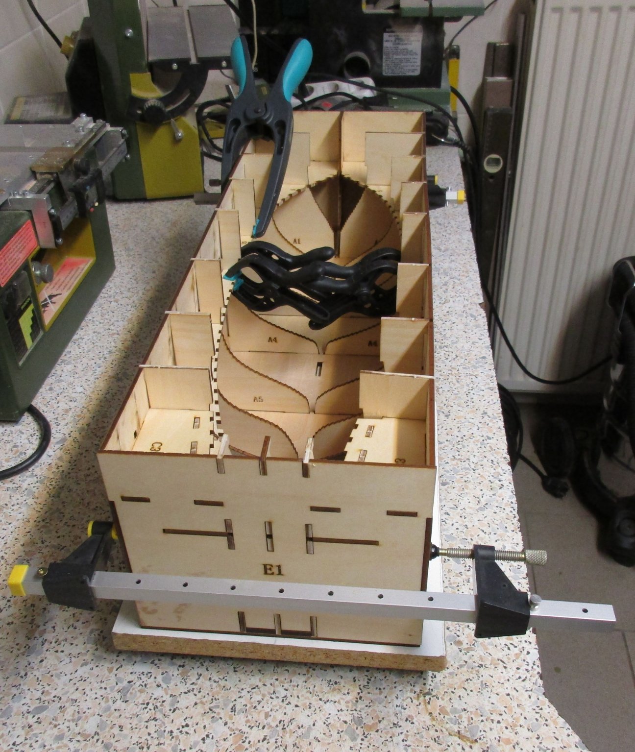
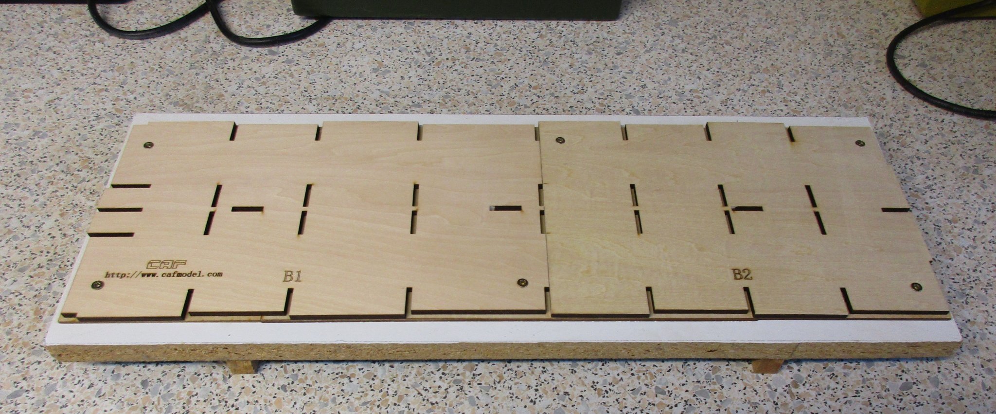
Thanks for your interest and Likes! I have started to take care for the building cradle parts and it's construction. The base plates B1 – B5 have been screwed down to a solid board as per the instructions. The keel has been placed and Plywood pieces A and C so far are only cleaned up and dryfitted, Most of the parts A1 – A7 are not holding tight the keel laterally, I will install some additional guides to hold the keel in position firmly. The stem post pattern part A8 requires some grinding to fit the contour of the lower stem and it's proper spot in the cradle. Instruction manual 1, figure 19 shows the installation of the two end plates E1 and E2. Unfortunately both pieces are missing in my kit. I will check out if it is possible to create a solid and accurate cradle without the pieces. More to come....