RMC
-
Posts
933 -
Joined
-
Last visited
Content Type
Profiles
Forums
Gallery
Events
Everything posted by RMC
-
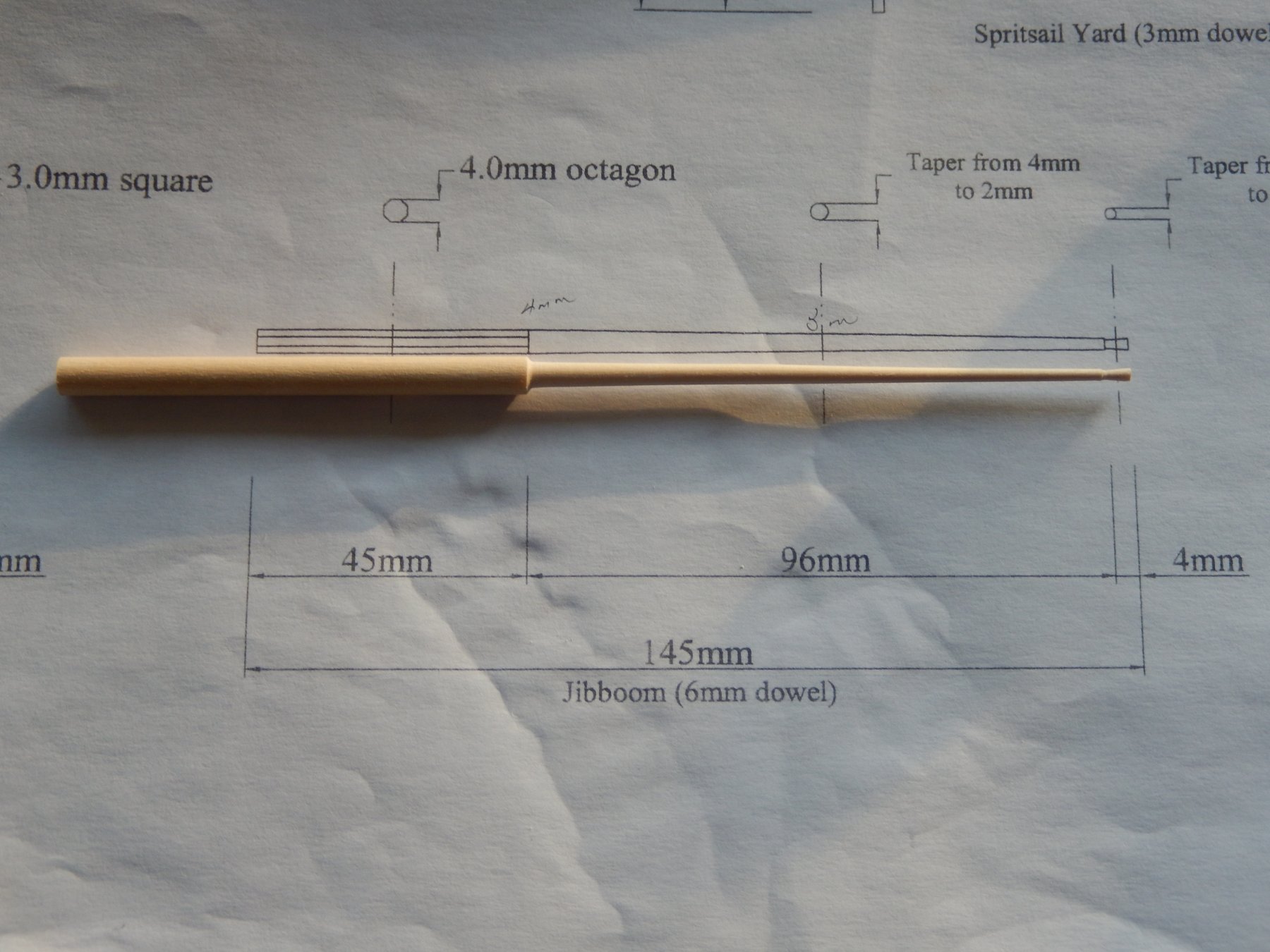
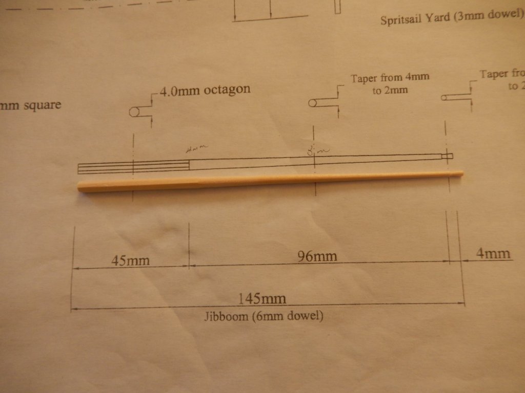
The various tops are now done. One thing to note: here are no rigging holes provided as there should be for the mizzen topmast top. Drilling them once the masts are stepped would be difficult. The following photo shows up every fault. In the flesh it's not too bad. I presume the parts are laser-cut, but the cuts are not really clean and it's hard to get rid of the rough centre of the ply. It shows most on the smallest of the tops and I see I will have do some touching up. The jibboom is shown dry-fitted below.

- 421 replies
-
- 8
-

-
- caldercraft
- granado
- (and 1 more)
-
After gluing the completed square section to the mast it then became obvious that this was a rather large mistake. Belatedly I realized that the only way the main top would fit was to slide it up from the bottom of the square section. The crosstrees and the trestletrees are a very snug fit around the 7x7mm square. The round section at the bottom of the mast is 8mm in diameter so no go there; the top of the square section has cleats and other bits and pieces on it so no go there either. I then discovered that I had done a really good job of gluing the damn' thing on, but it eventually it came off. Fortunately my 7x7mm was pretty accurate, but I suggest before doing anything make sure the cross- and trestletrees fit. I suggest only after the top is dry-fitted should the bibbs be fitted, then the top glued in place. Here is the completed square section. The colour shown is an artifact of the light. In the flesh it looks quite good. The second photo does not show much detail, but the colour is fairly accurate.

- 421 replies
-
- 9
-
-
- caldercraft
- granado
- (and 1 more)
-
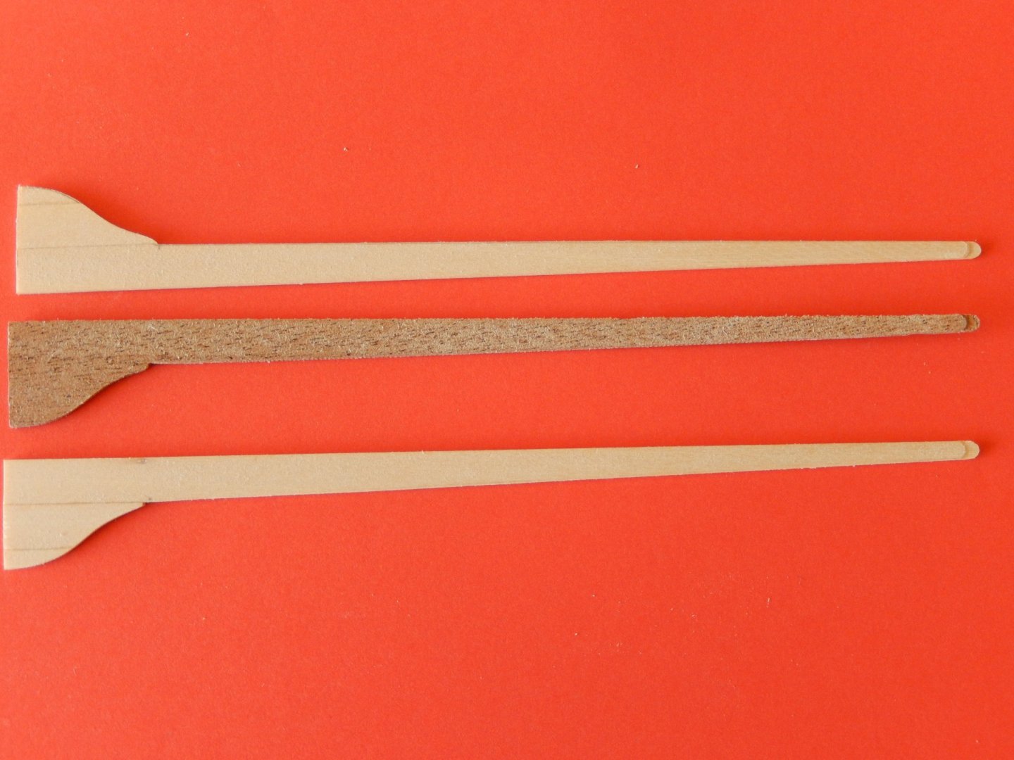
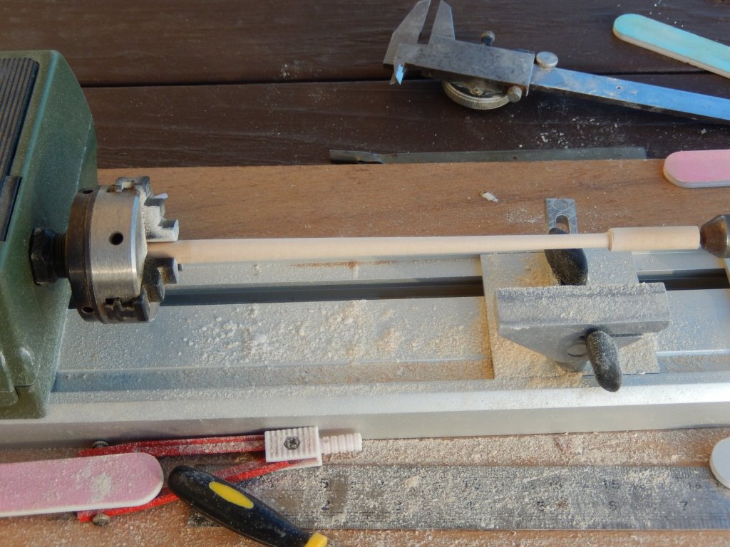
Work has begun on the main mast. The Proxxon lathe made the tapering straightforward. The square section at the top of the mast is supposed to be a piece of 7x7mm walnut. Unfortunately it was missing from the kit. This did not make my day. Having said 'Gosh, what a nuisance' or words to that effect, I found some 8x8mm boxwood and sanded it down to the correct dimensions. Dry-fitted: The bibbs supplied in the kit are plywood of very indifferent quality. Aside from this, as I will not be staining the masts walnut, the light-coloured mast and the walnut bibbs will, I think, make a poor match. I have made up replacements which I hope will not look out of place. The top part of these will eventually be painted black.


- 421 replies
-
- 11
-
-
- caldercraft
- granado
- (and 1 more)
-
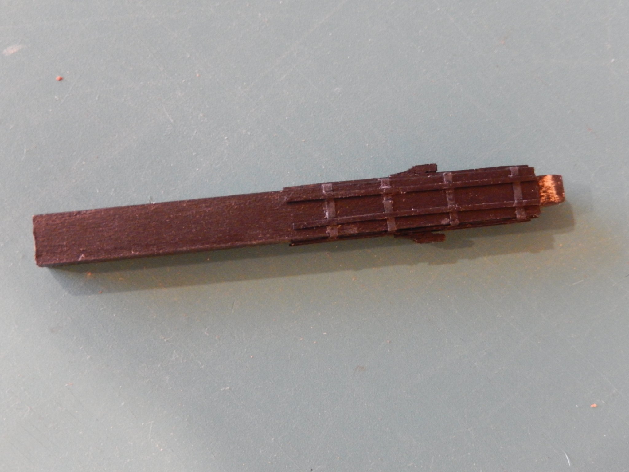
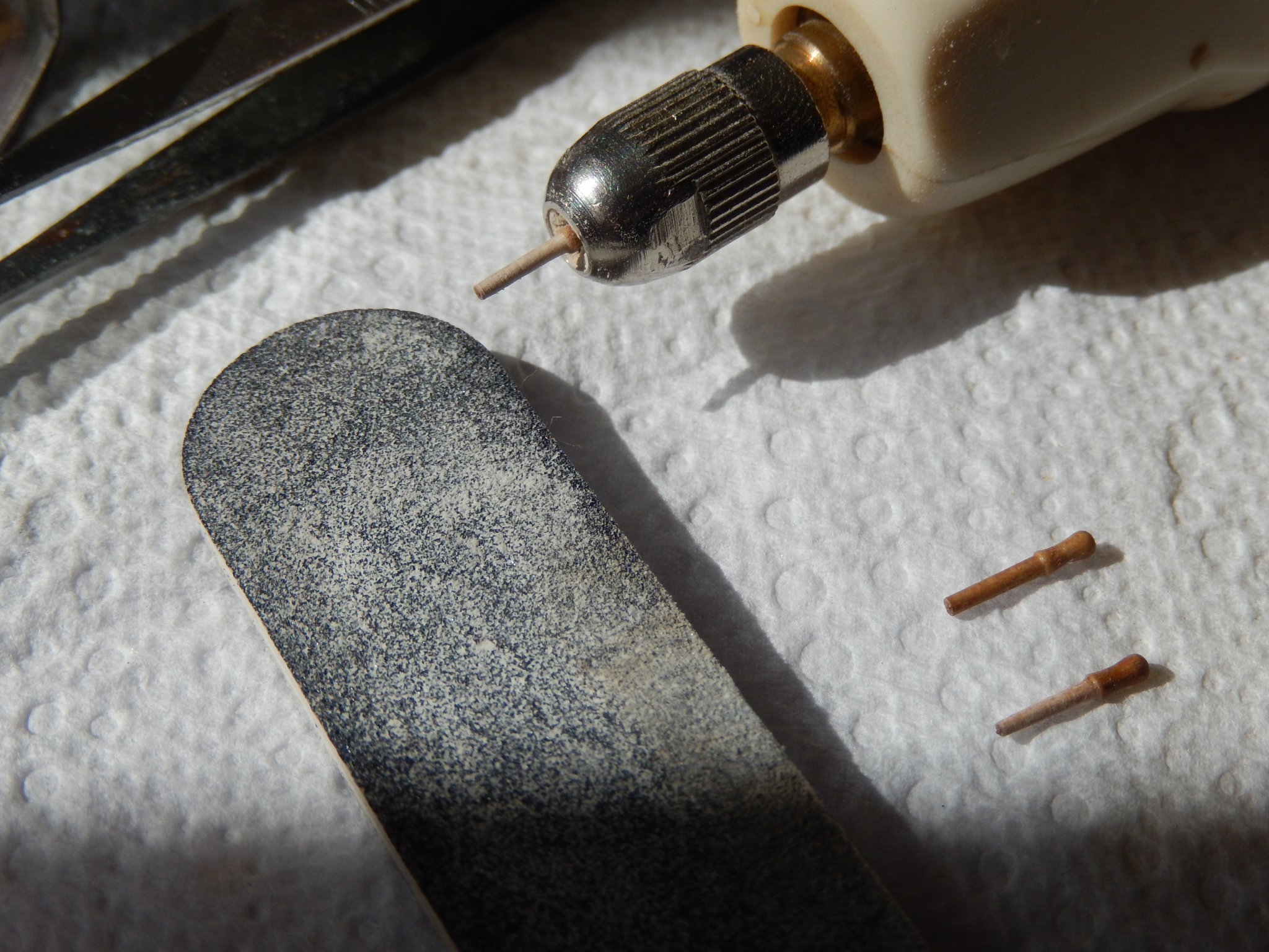
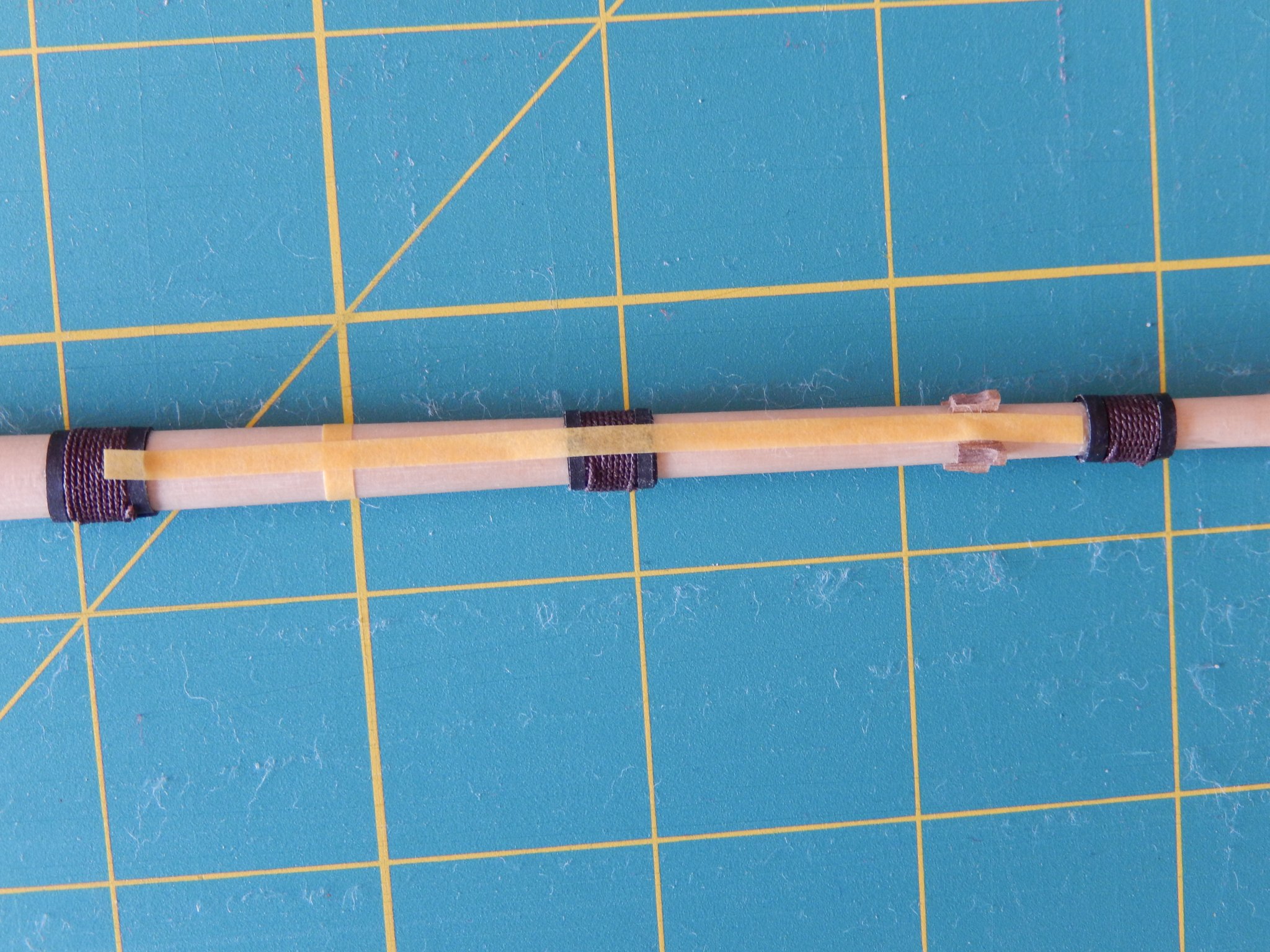
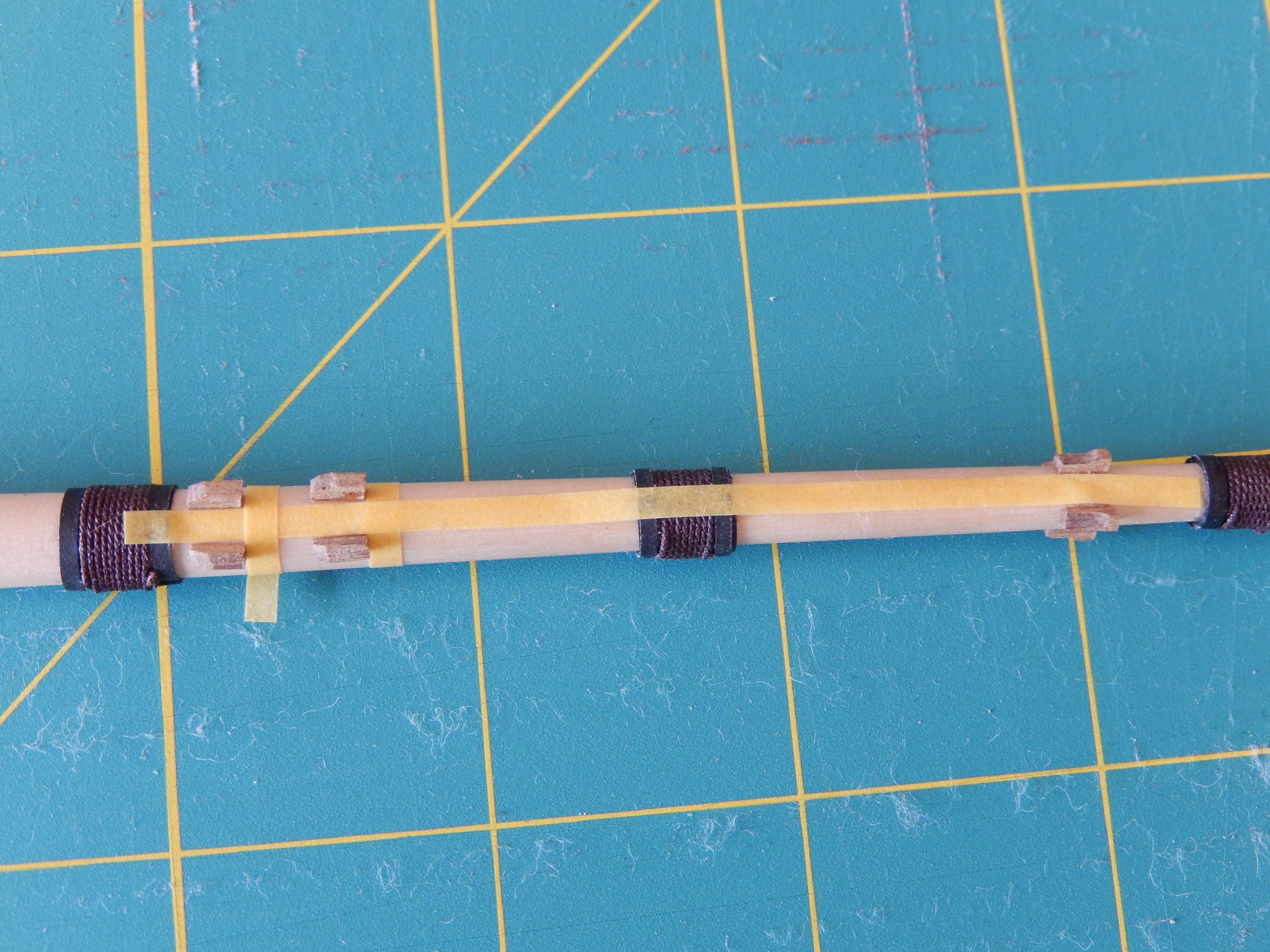
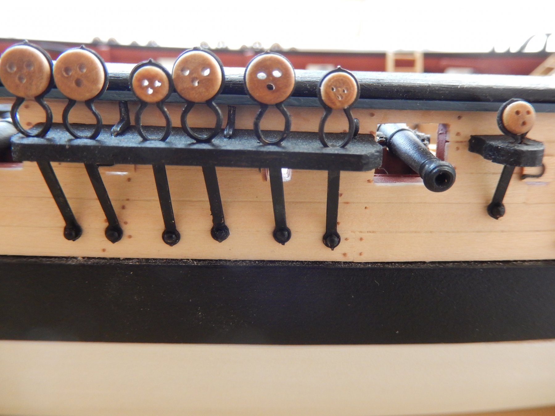
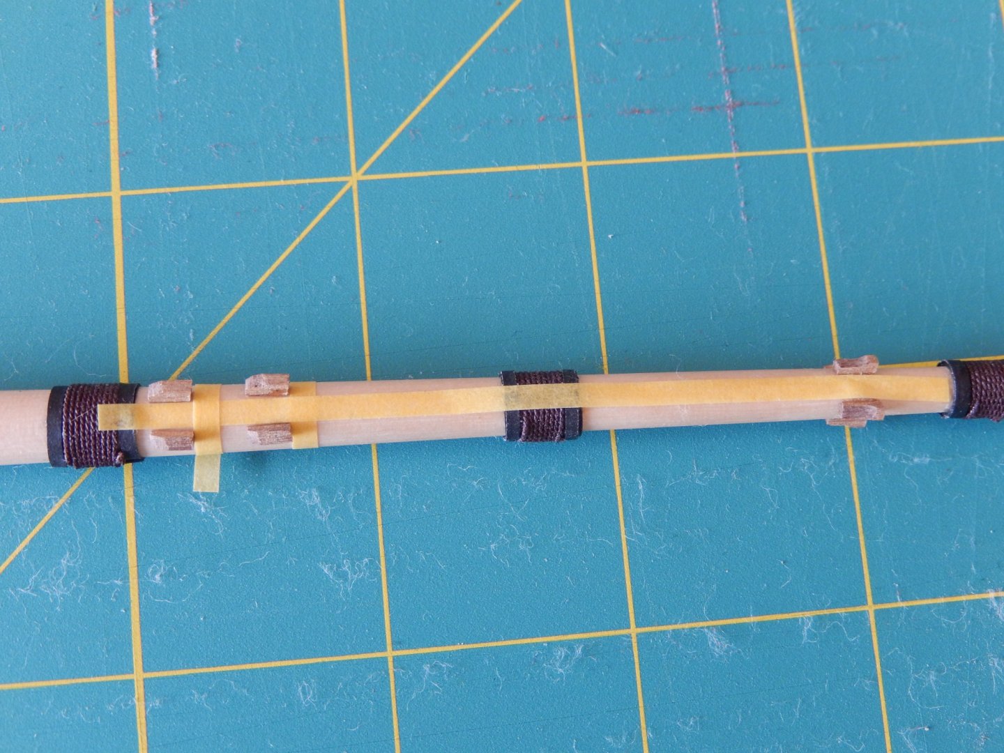
Having done most of the household things that need to be done after being away for a while, it's time to get serious again. Here are a couple of little jobs that needed to be done. First, the belaying pins did not fit in the holes provided. Here is an easy and obvious way of solving that small problem. Positioning the gammoning cleats is quite fiddly. I used narrow masking tape as a guide. The instructions suggest the bowsprit be stained walnut. I tested it on a similar piece of timber and was not happy with the result. The timber supplied for the cleats is walnut and as I didn't have any light-coloured timber of the right size I have gone with the walnut. Having seen the result I'm not too happy about that either. You can't win. I hope that with all the other things that will eventually be going on the bowsprit, the mismatch in timber colours will be overlooked.


- 421 replies
-
- 10
-
-
- caldercraft
- granado
- (and 1 more)
-
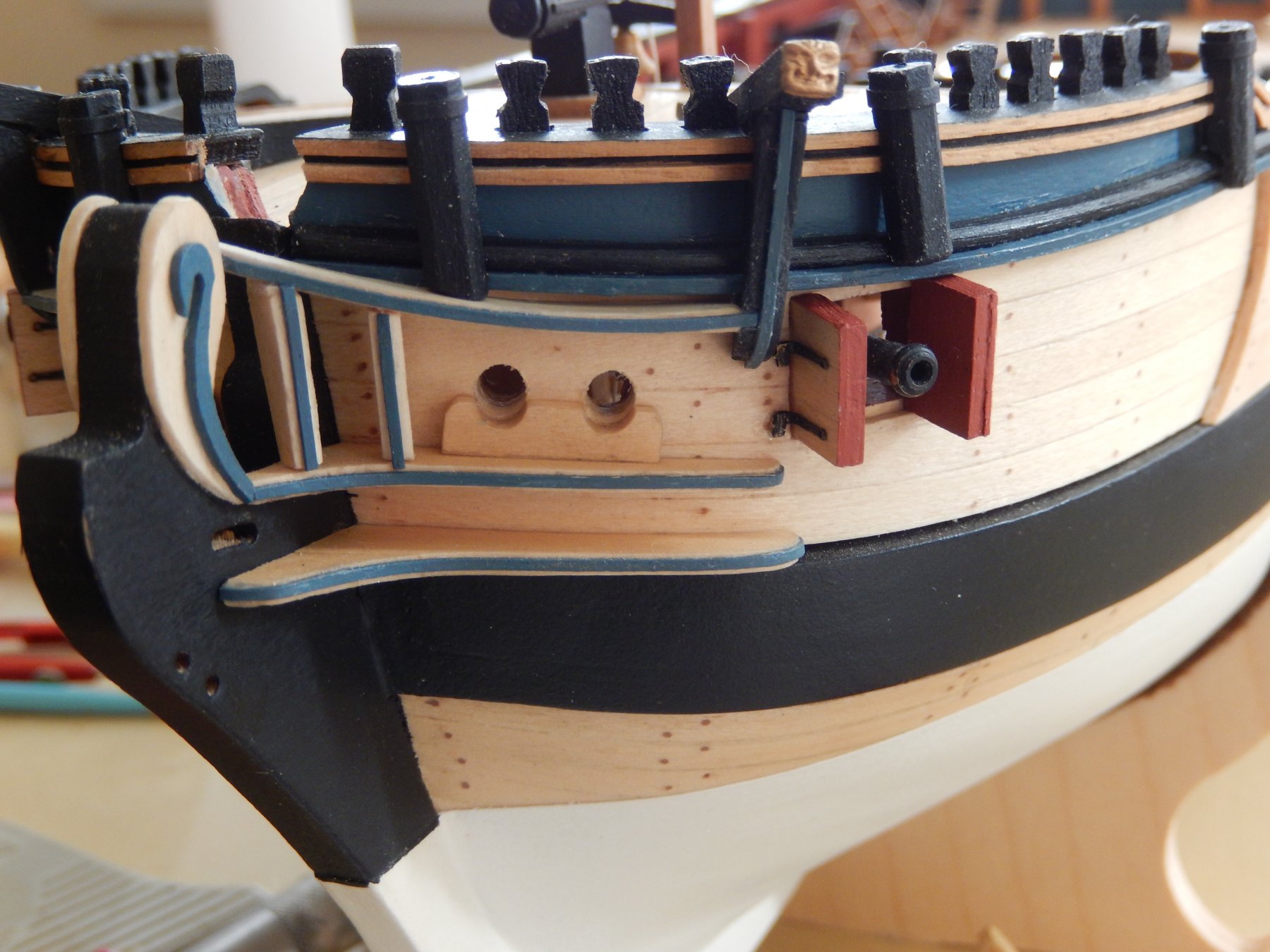
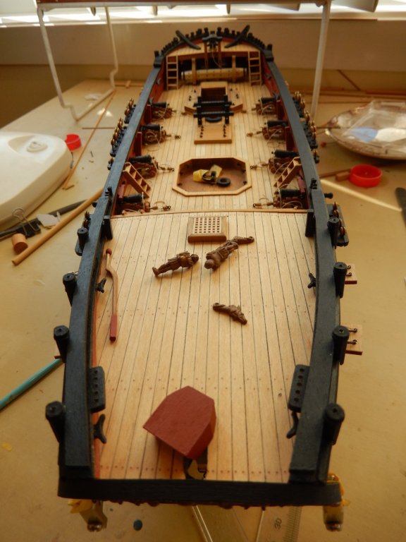
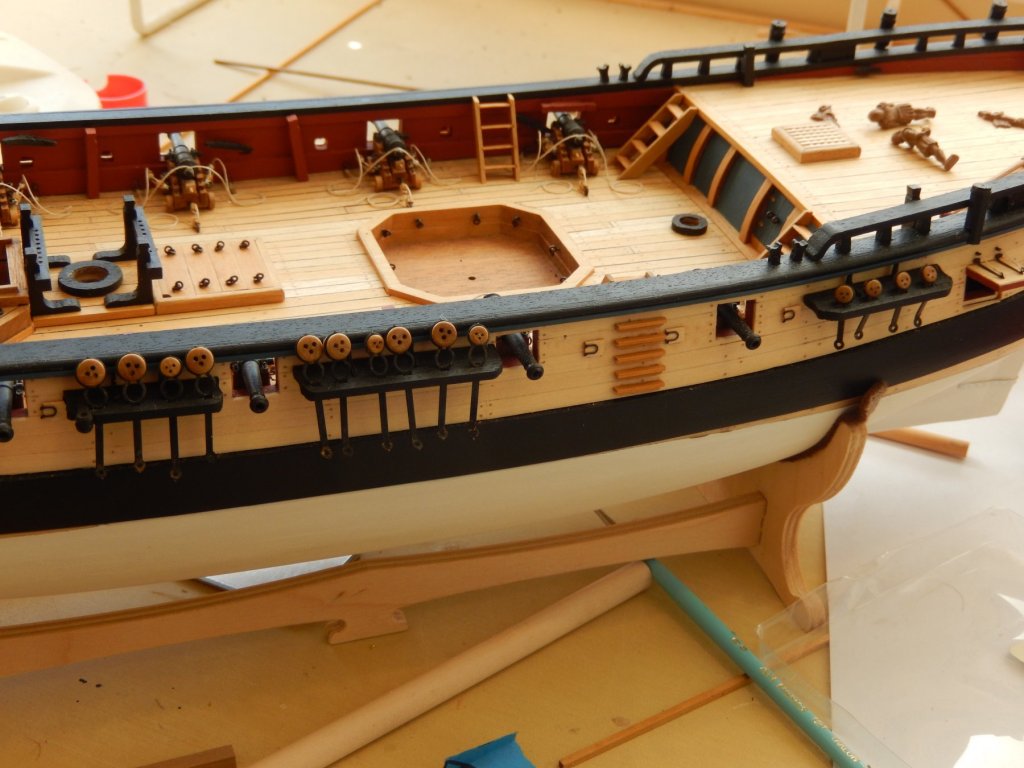
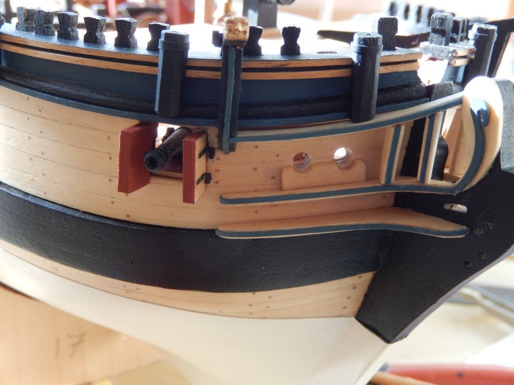
The channels etc. are finally done. When, some time ago, I made one of the rowing ports with its little door open, I made the mistake of choosing one that turned out to be under the middle channel. This was not a good idea. Not only does it obscure a rather nice feature, the little door makes life difficult when fitting the channel. You may just see it in the following photo. Most of the deck fittings have now been finished and it's now just a process of putting them in place. They will have to wait as I will be going away for 3 or 4 weeks on Thursday and household chores need to be done.
- 421 replies
-
- 10
-
-
- caldercraft
- granado
- (and 1 more)
-
Thanks Scott. It is great, but it doesn't seem the happen very often.🙂
-
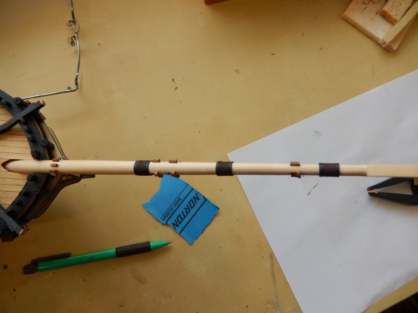
To my rather pleasant surprise, the bowsprit and the jibboom go together quite nicely. Here they are joined by the cap. They are dry-fitted and held by gravity. Well they would have been here, but again the uploads were knocked back. Tried again later. Joy.

- 421 replies
-
- 10
-
-
- caldercraft
- granado
- (and 1 more)
-
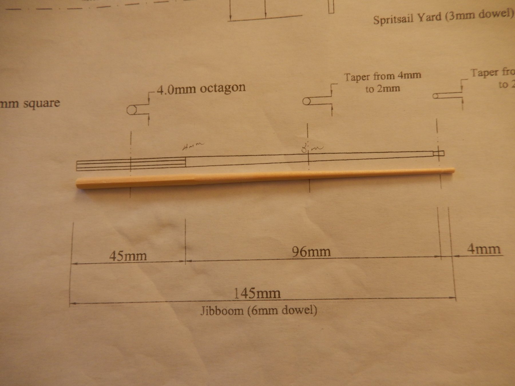
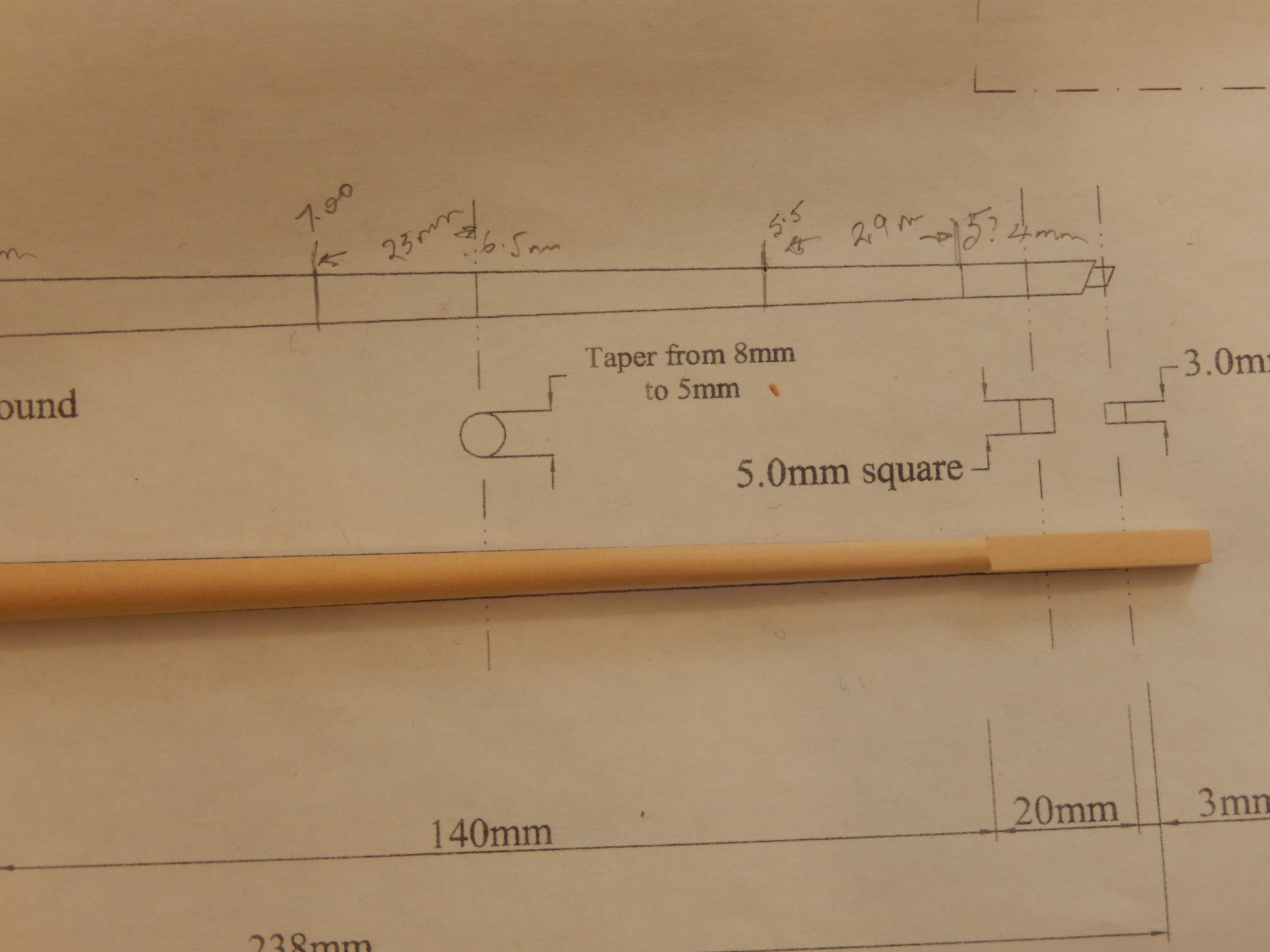
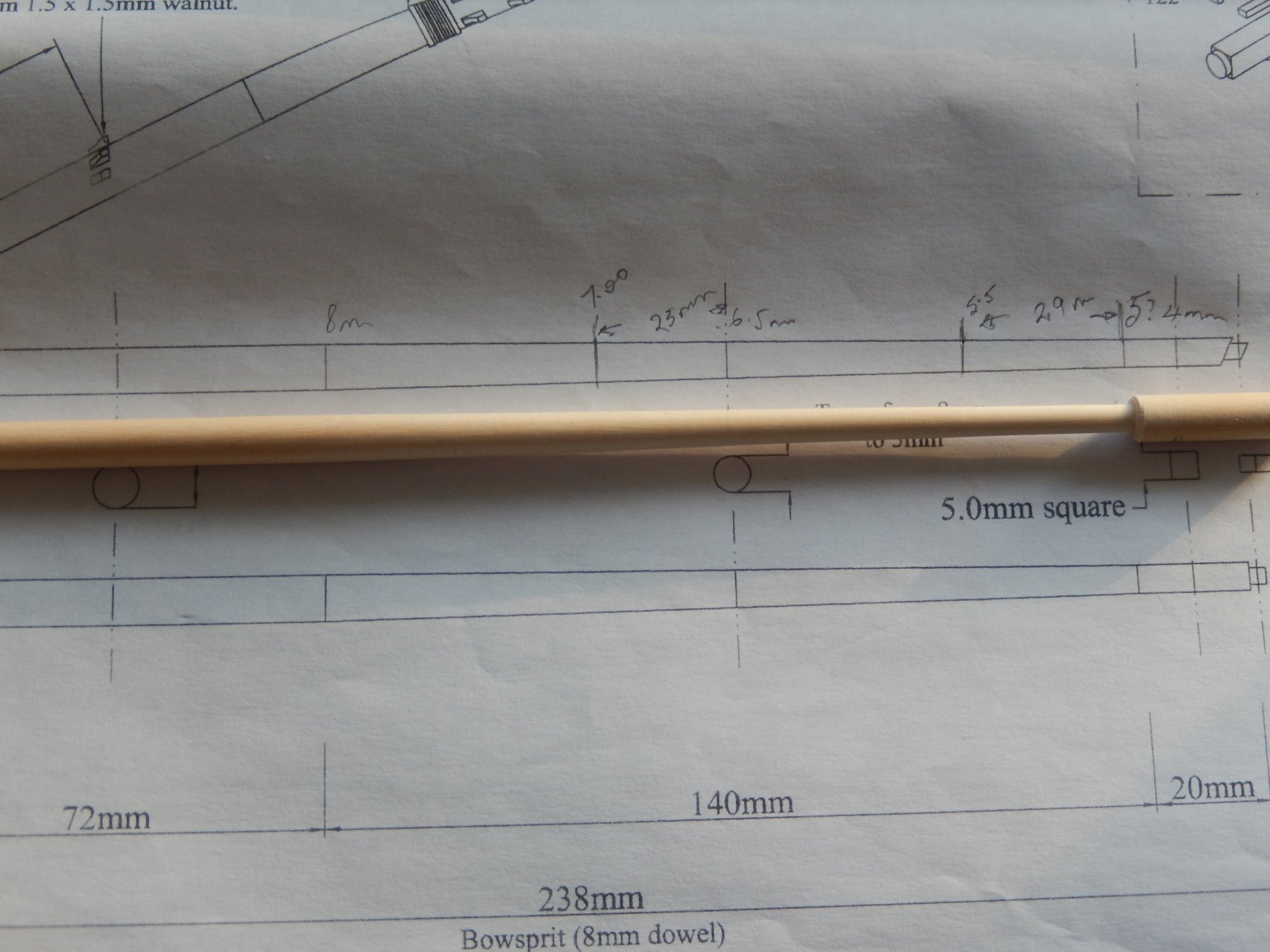
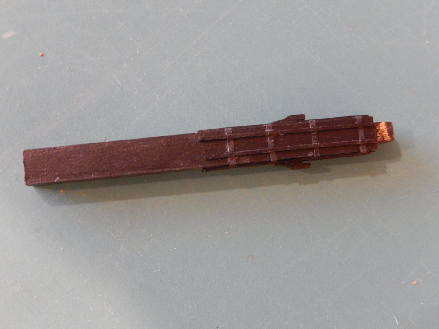
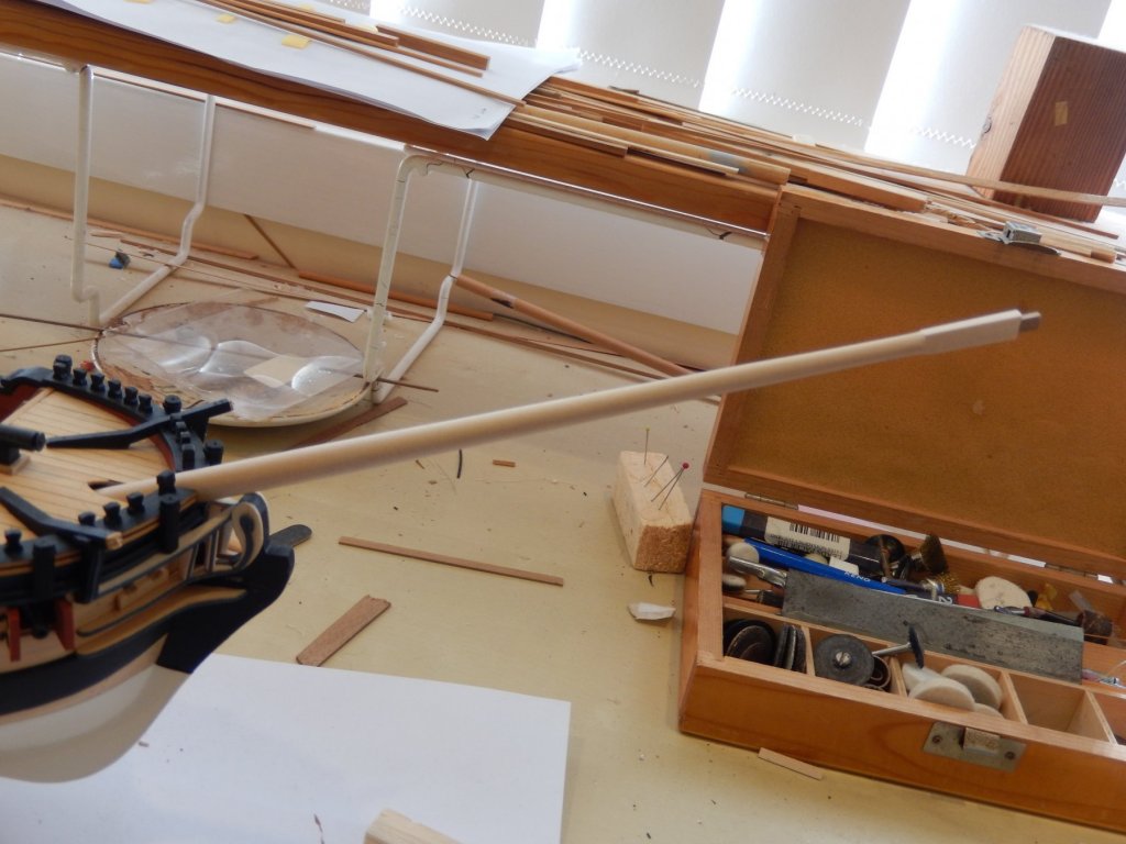
Here are some photos of progress on the bowsprit. First, holes were drilled in to both ends to receive the small round and square-sectioned extensions. Both ends were then cut off at the required angle. The bowsprit dry-fitted .... ....and the jibboom.


- 421 replies
-
- 4
-
-
- caldercraft
- granado
- (and 1 more)
-
The bowsprit has come out well. However the upload speed for photos is glacial so I'll try another time.
-
Thanks Joe for the reassurance.
-
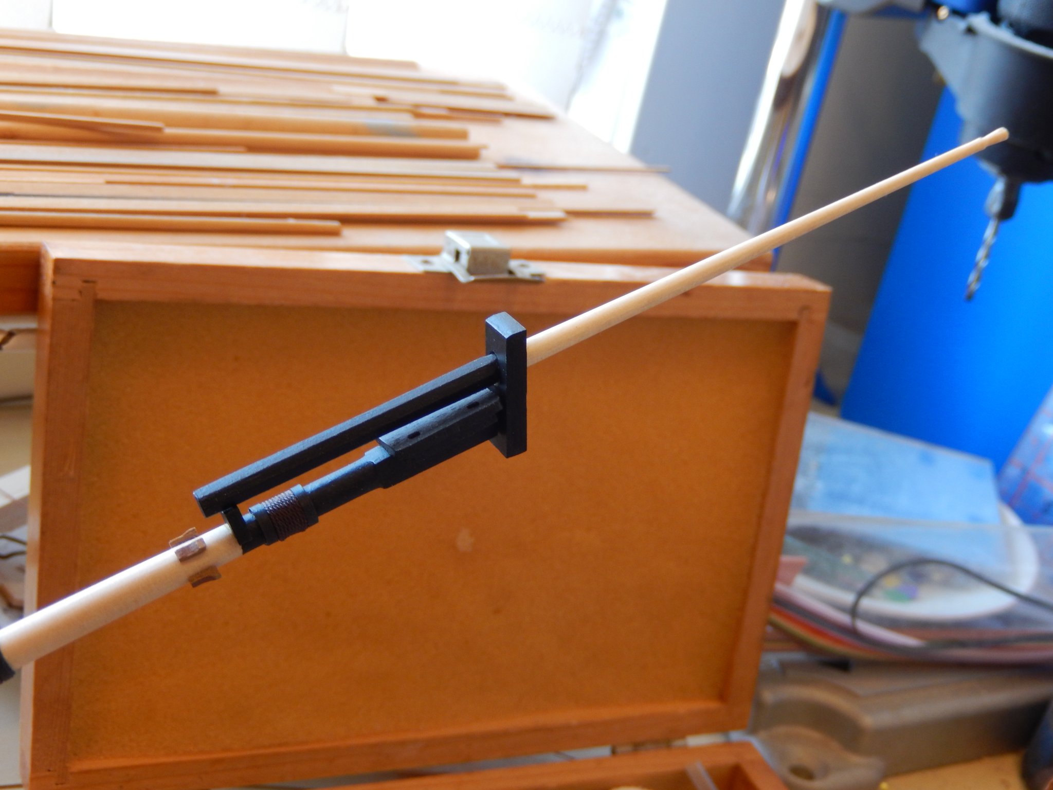
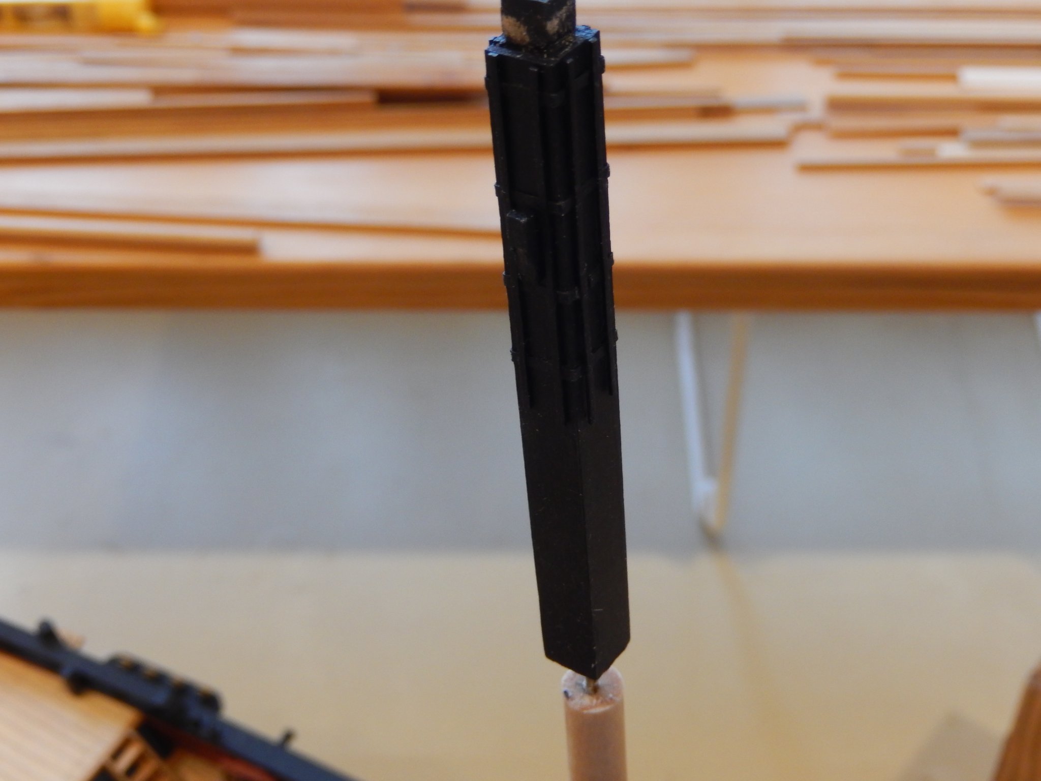
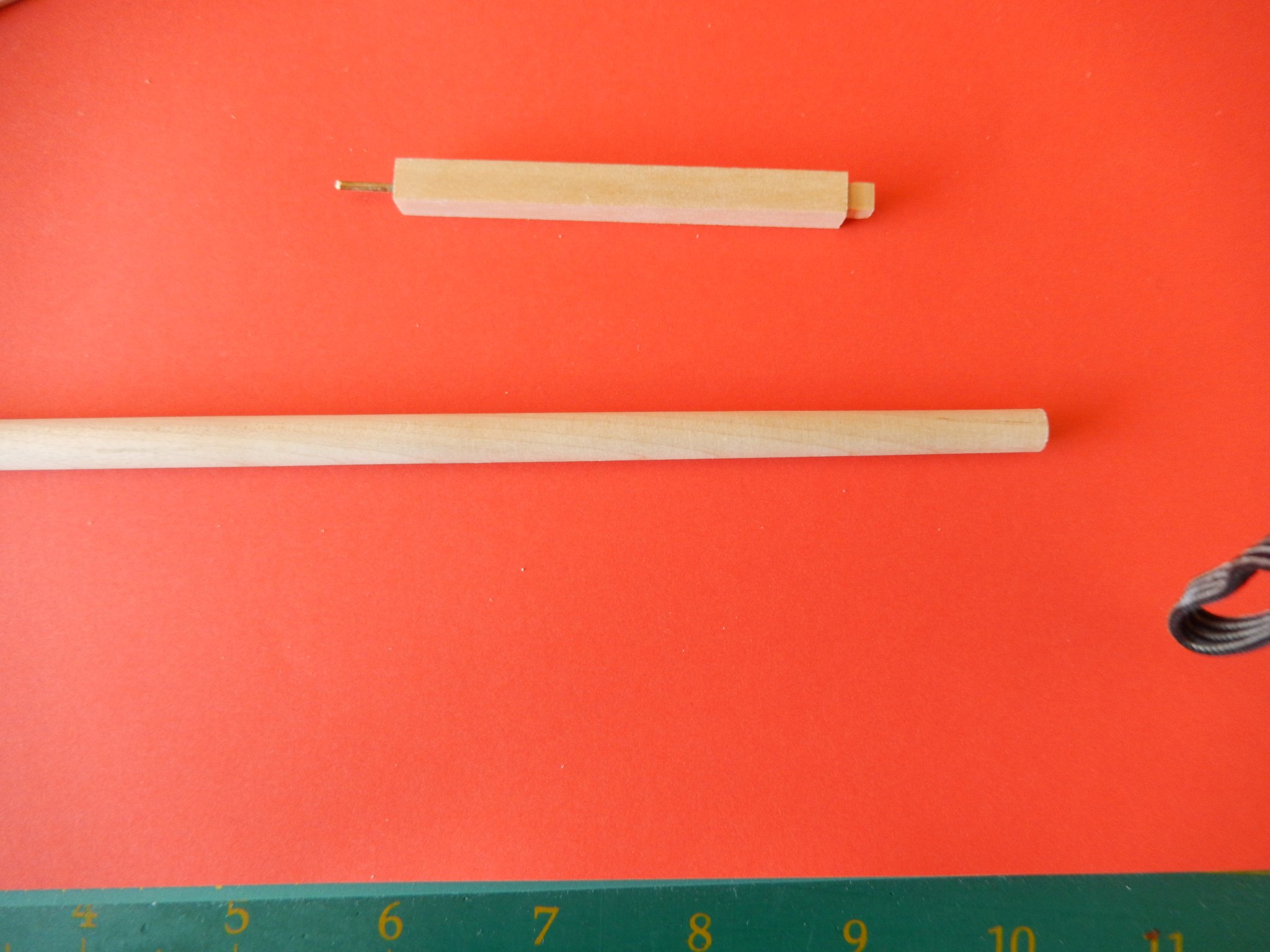
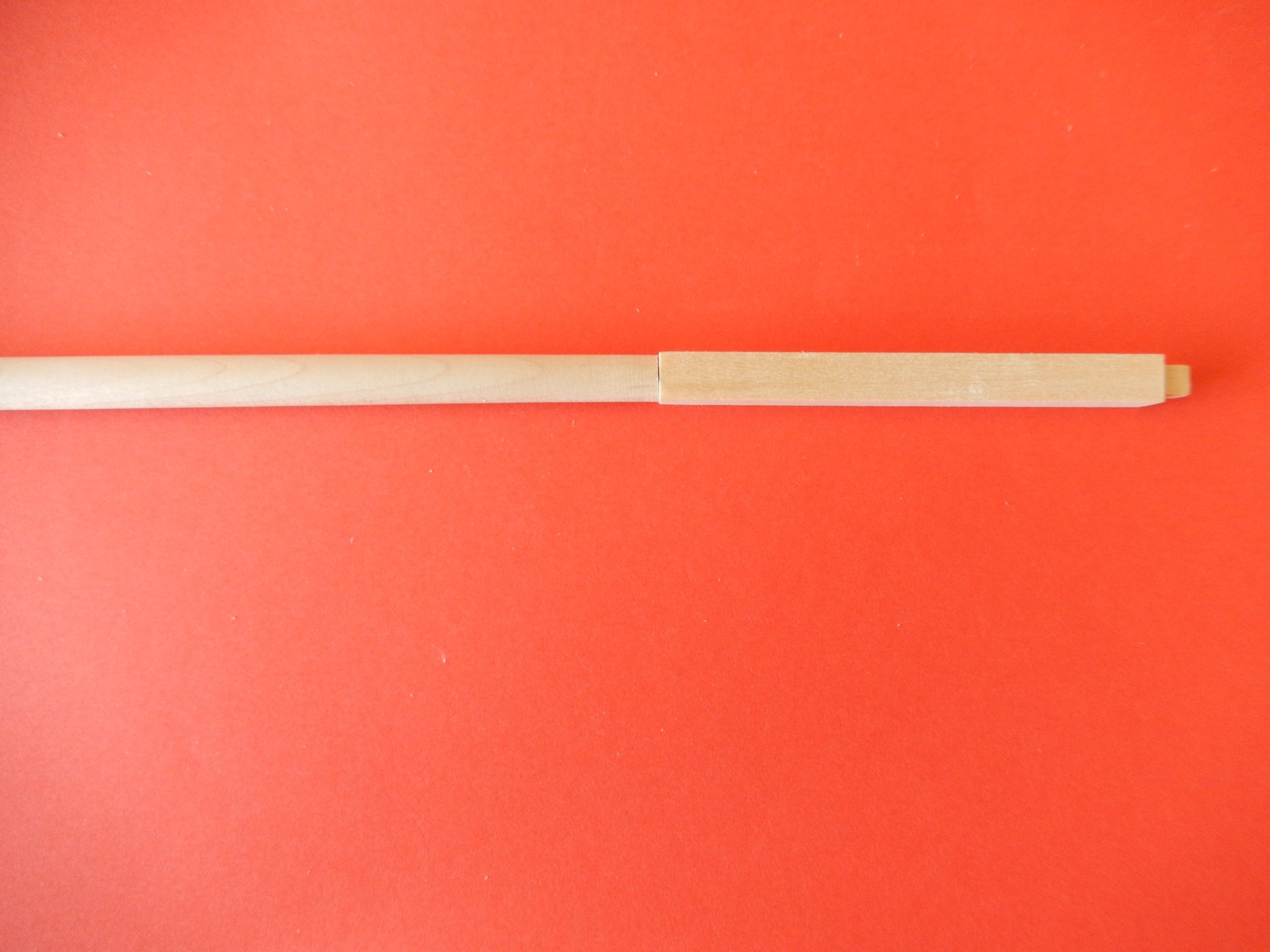
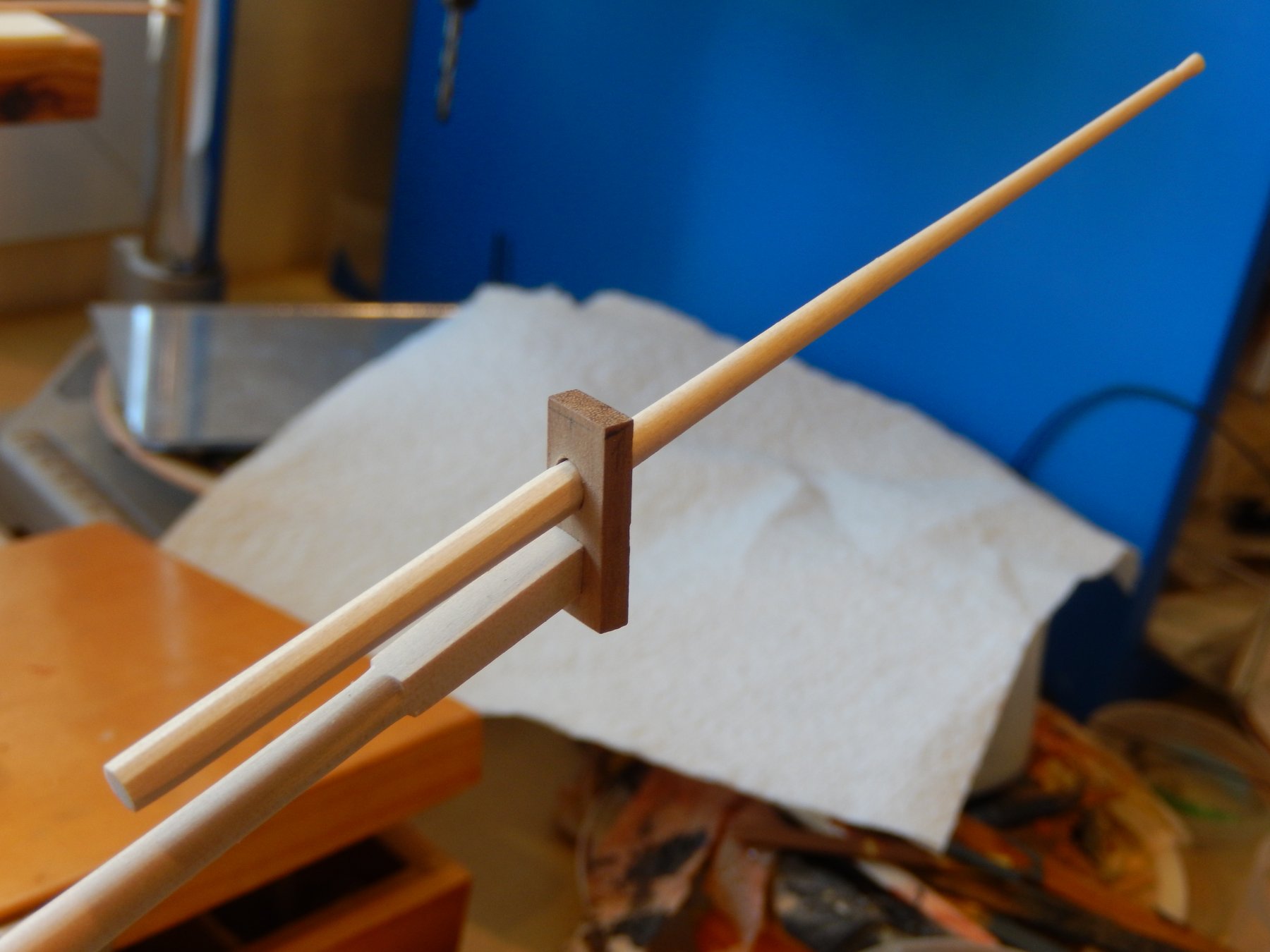
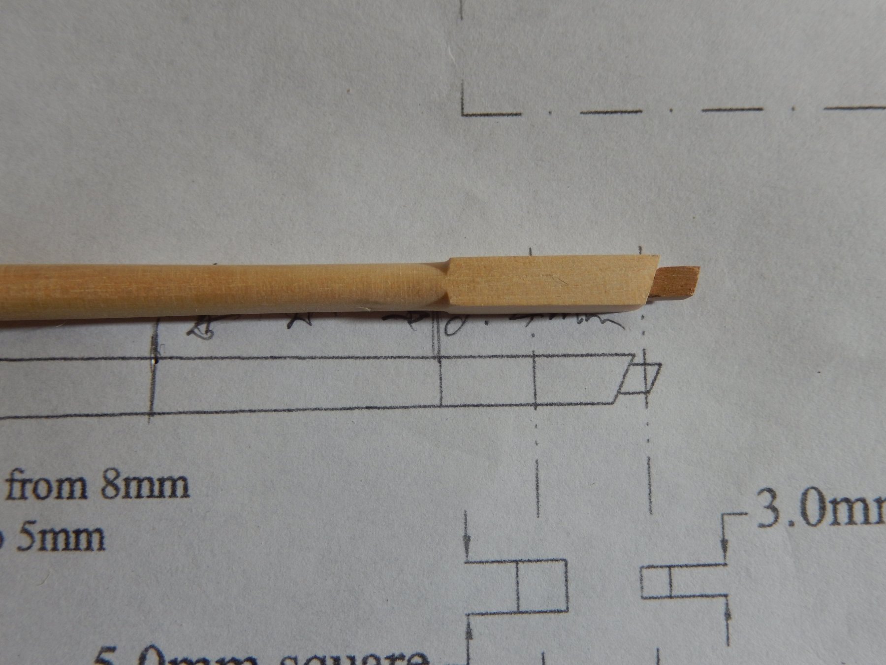
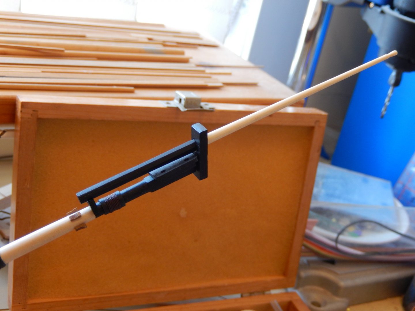
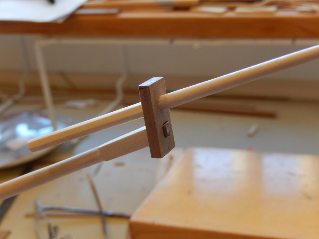
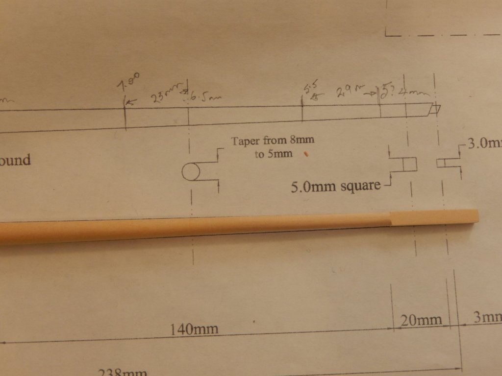
I have continued work on the bowsprit and have completed the 5mm square section at the tip. I am now considering how deal with the 3mm square which extends from it and into the bowsprit cap. While 'squaring' the end of the bowsprit was not all that difficult (shown below), I have doubts about my ability to cut down the 5mm square to 3mm while obtaining the correct angle for the cap. At this stage I think I'll cut the 5mm square at right angles, then drill a deep 3mm hole in its centre. The right angled cut would then be adjusted to the correct angle for the cap, then a piece of 3x3mm timber would be fitted to the hole. Suggestions are welcome.
- 421 replies
-
- 10
-
-
- caldercraft
- granado
- (and 1 more)
-
I used the corner of an ordinary chisel (ie: holding the chisel at roughly a 45 deg angle to the dowel so that the edge just touches, and then gradually moving it along the support). This also tends to get rid of any variation in the dimensions of the dowel. I used this method to take the dowel close to the required dimensions, then sanding sticks to finish.
- 421 replies
-
- 2
-
-
- caldercraft
- granado
- (and 1 more)
-
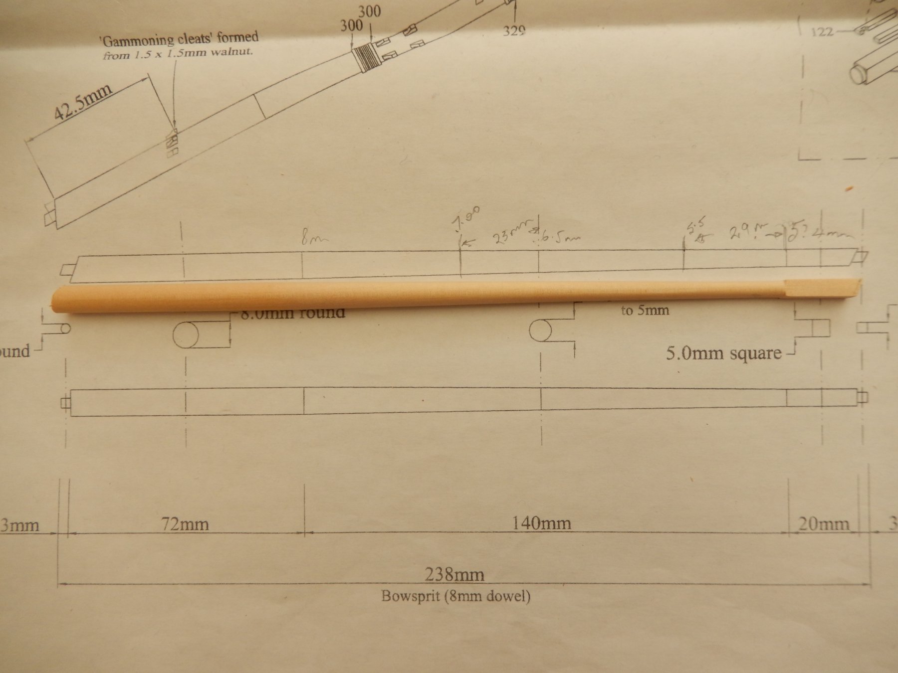
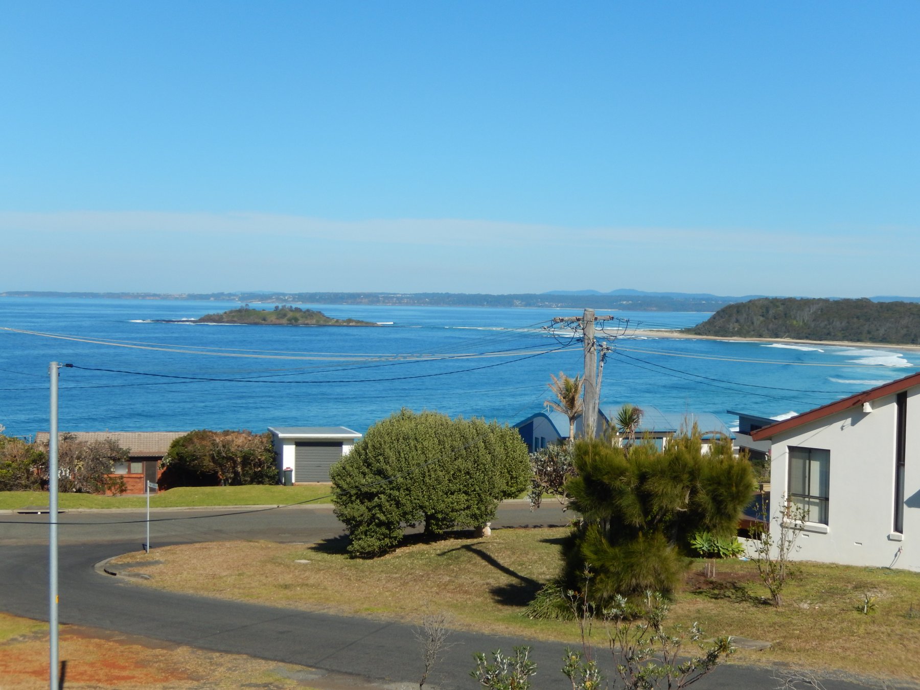
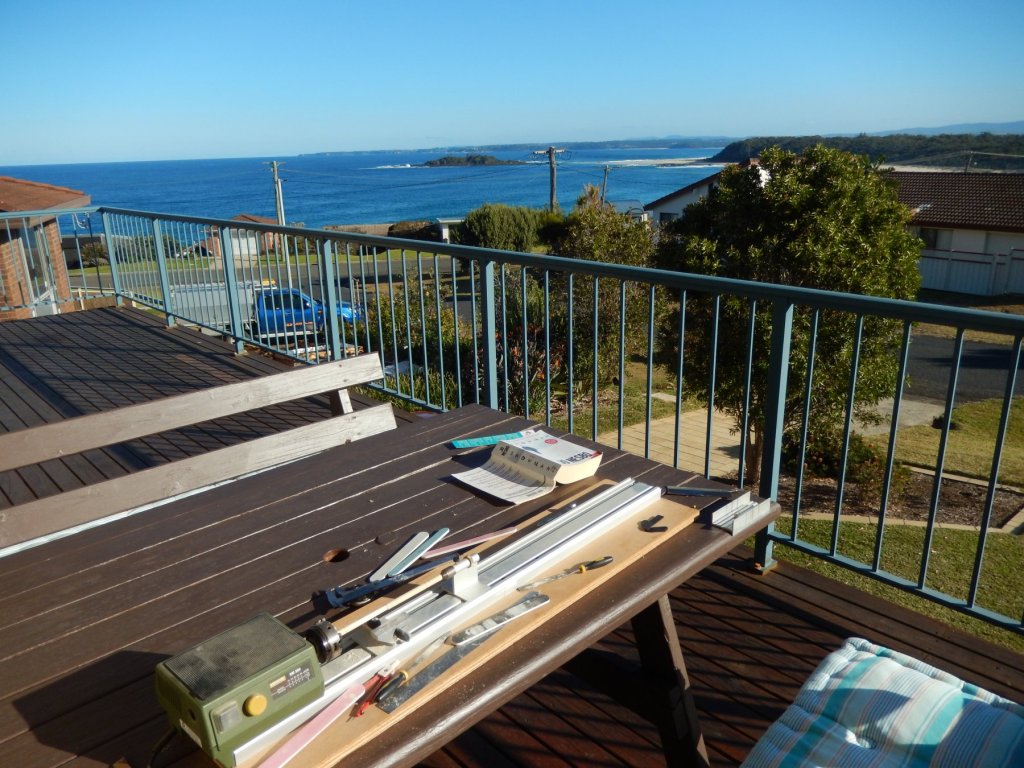
While away for the weekend I started work on the bowsprit. I'm afraid I couldn't resist showing a perfect winter's day two hours south of Sydney. Working outside saves the dust from the wood turning. The following photo and the first, above, show the Proxxon lathe which works a treat. Here is progress.


- 421 replies
-
- 9
-
-
- caldercraft
- granado
- (and 1 more)
-
Thanks for the kind words mugje and thanks to others for the reactions (?). They really encourage.
- 421 replies
-
- 2
-
-
- caldercraft
- granado
- (and 1 more)
-
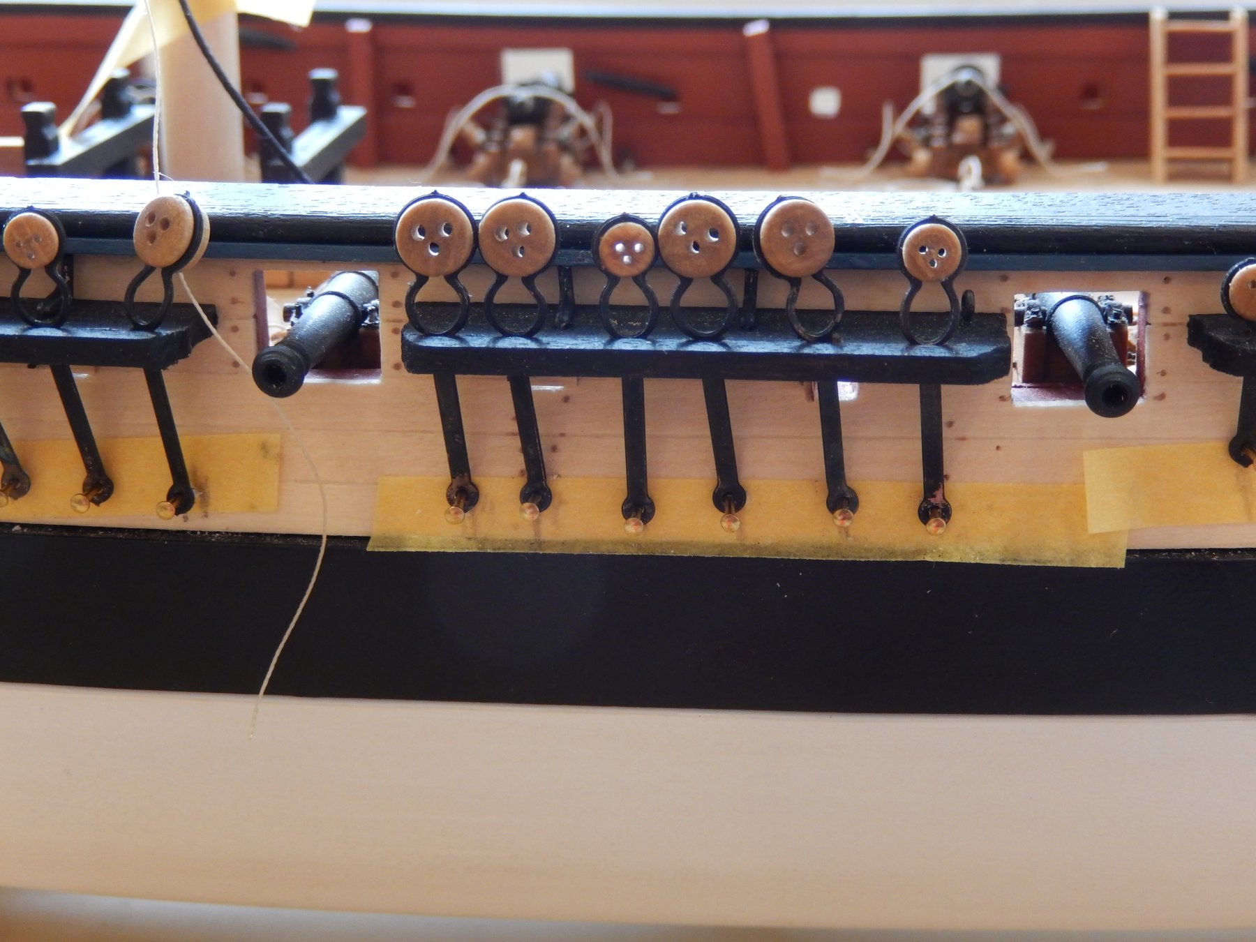
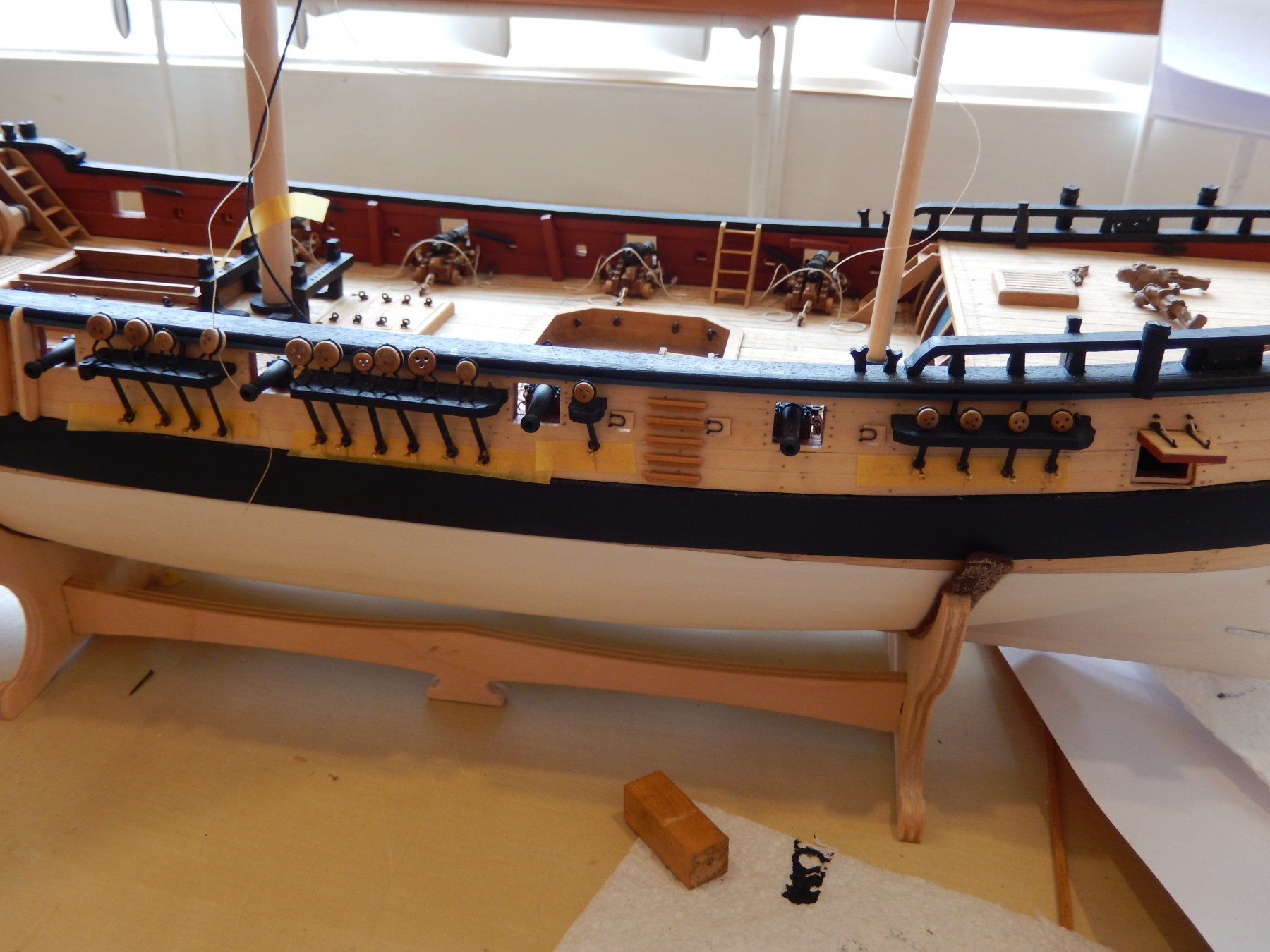
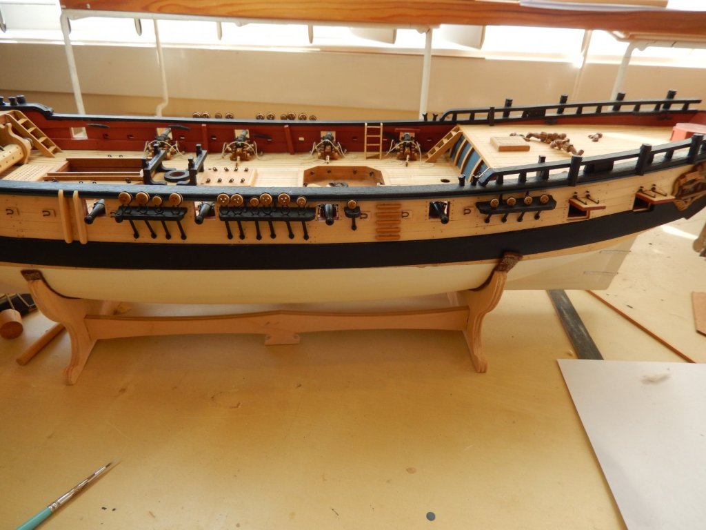
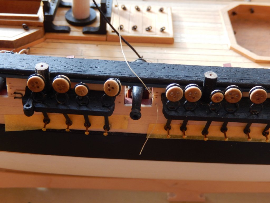
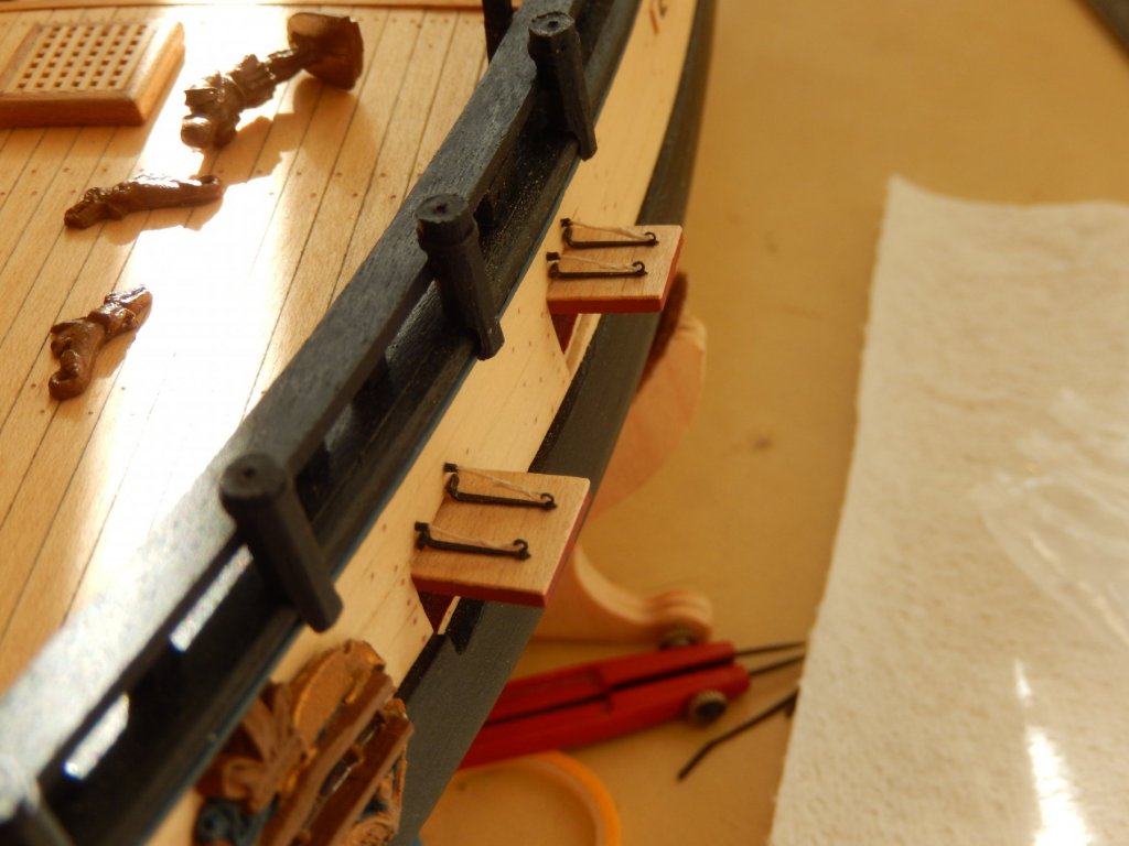
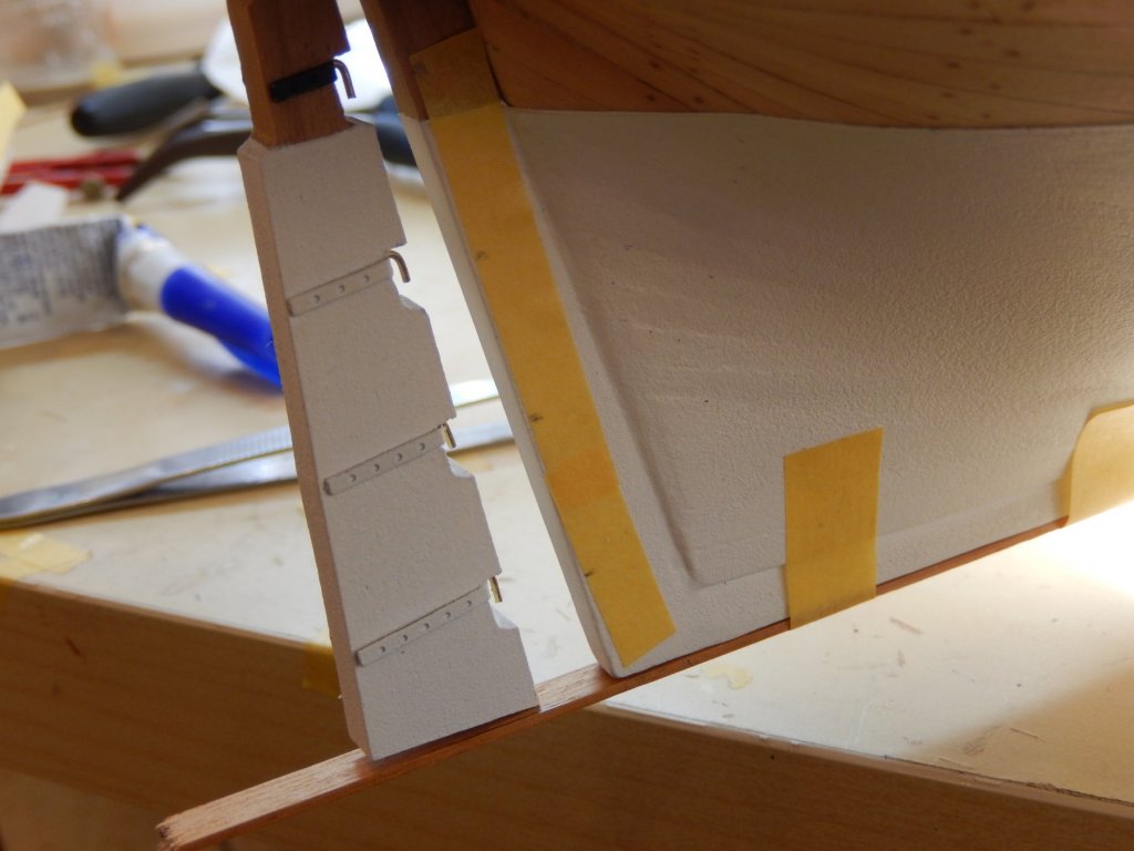
The channels and related bits and pieces are taking far longer than I thought. All of the channels, chain plates etc. are dry-fitted in the following photos. As you may see, I have used Tamiya tape upon which to mark lines established from thread tied to the masts leading to the chain plates. A pin was then put through the hole in the bottom of the chainplate which was then used to mark the place on the drawn line for the drill hole. I had made up all the pedestals for the guns, forgetting that four on them were over the channels. I cut down the four I had previously prepared to rest on the channels and cut their tops off at the appropriate height. Shown here they are dry-fitted and before being repainted.


- 421 replies
-
- 11
-
-
- caldercraft
- granado
- (and 1 more)
-
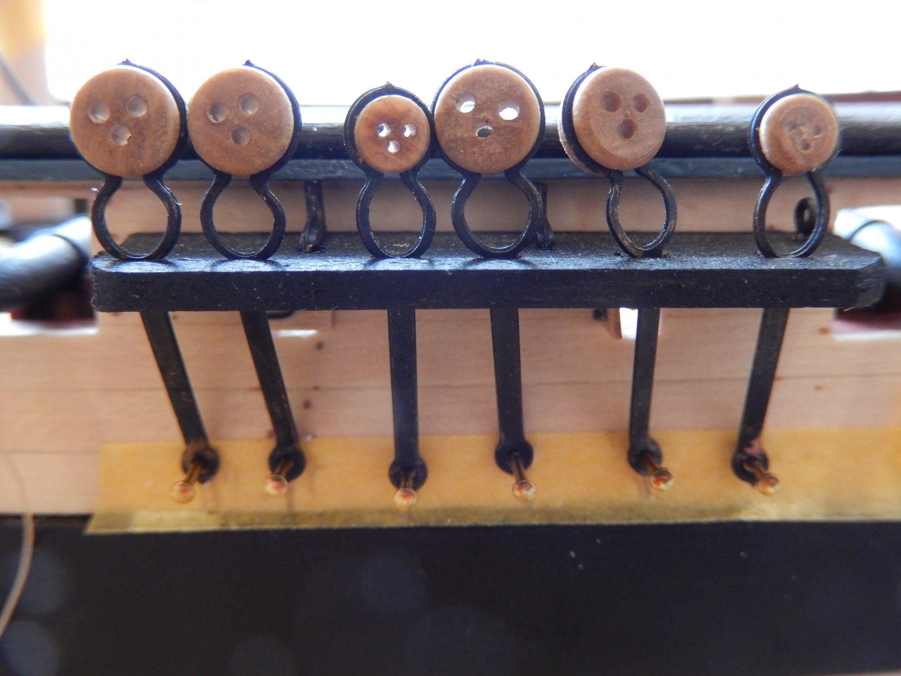
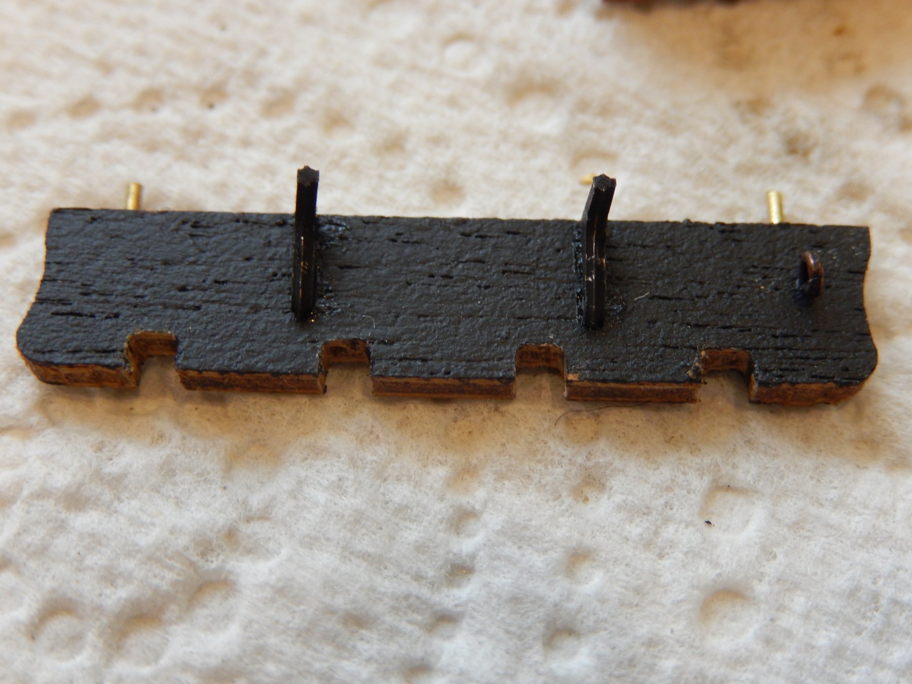
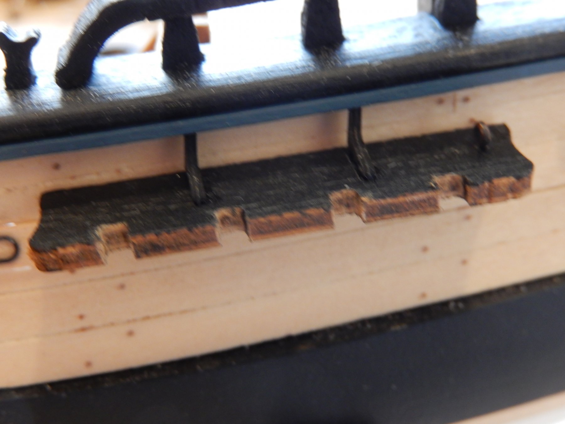
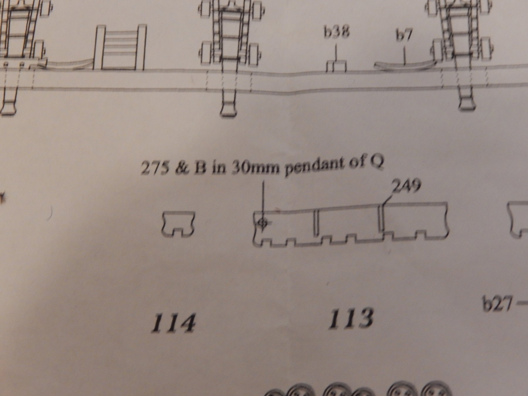
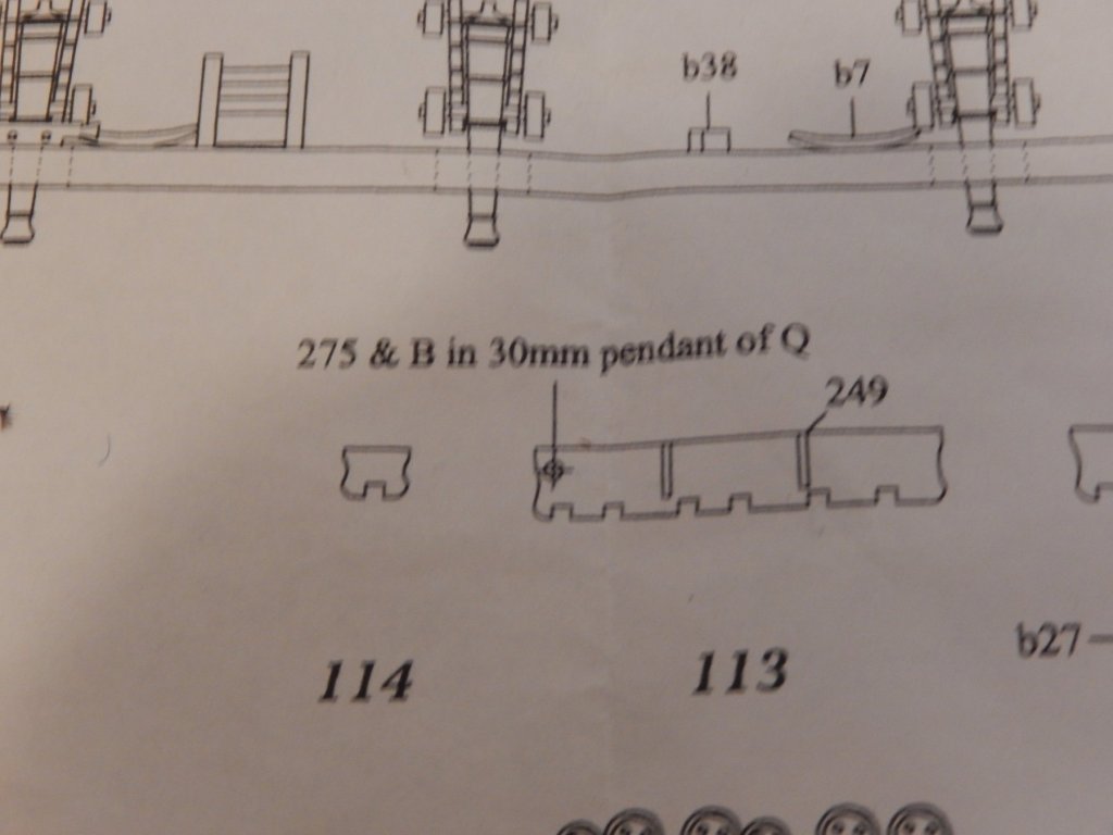
The channels on the port side are now finished but for some touching-up and a final coat of poly. They were quite time-consuming and I learnt a few things in the process. The channels supplied are made of very coarse ply, and of a colour inconsistent with the timber I have used for the hull. I have therefore painted them which to some extent masks the coarseness of the timber which is clearly shown in the following photo. Fortunately in the flesh, they are not nearly as bad. Here is that channel with knees , dry-fitted. I have no idea what the following instruction means: 'B in 30mm pendant of Q'. Here are three channels dry-fitted. The angles of the chain plates will be determined by temporarily fitting masts and running thread to each chain plate and to the hull.


- 421 replies
-
- 10
-
-
- caldercraft
- granado
- (and 1 more)
-
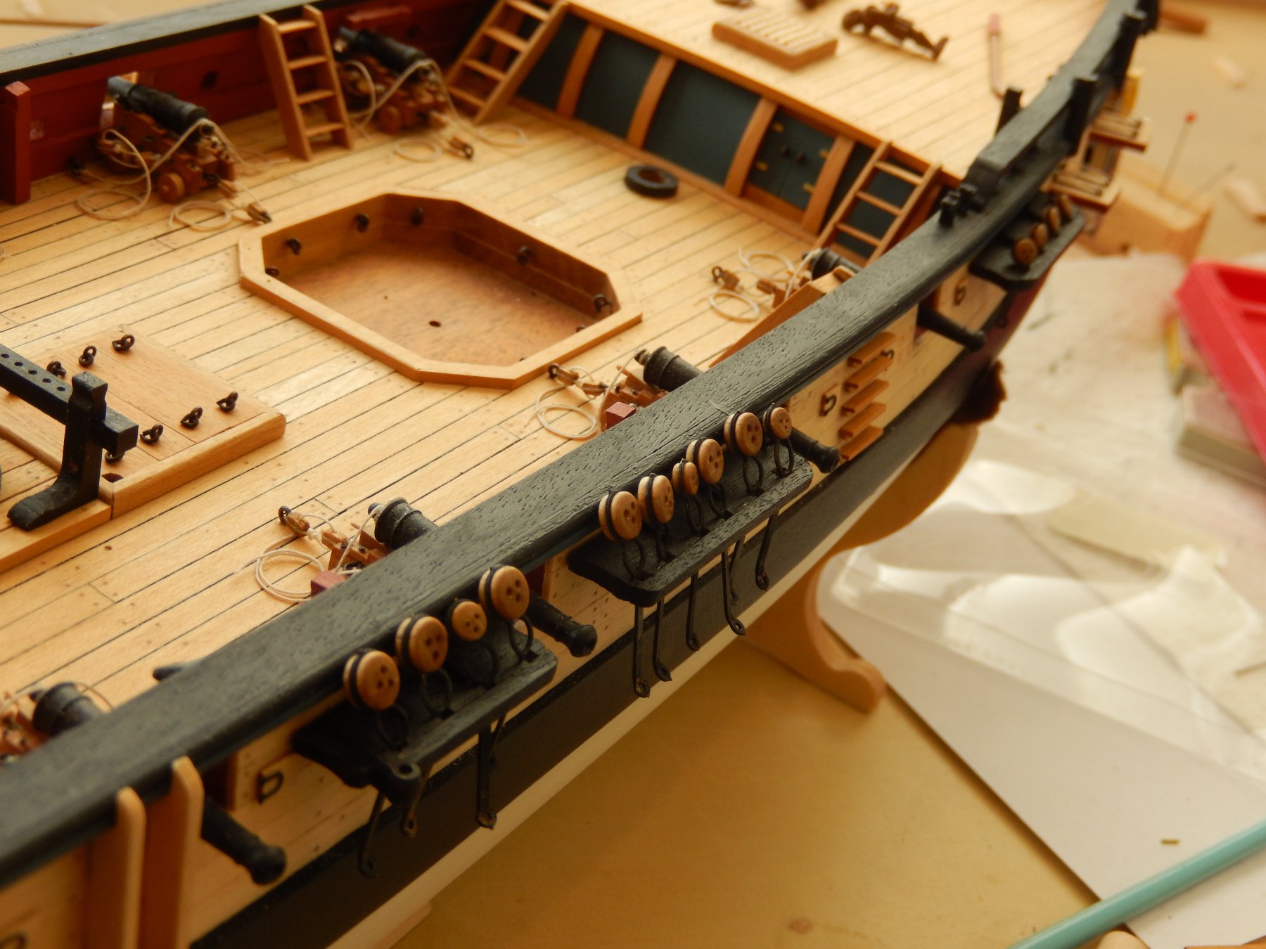
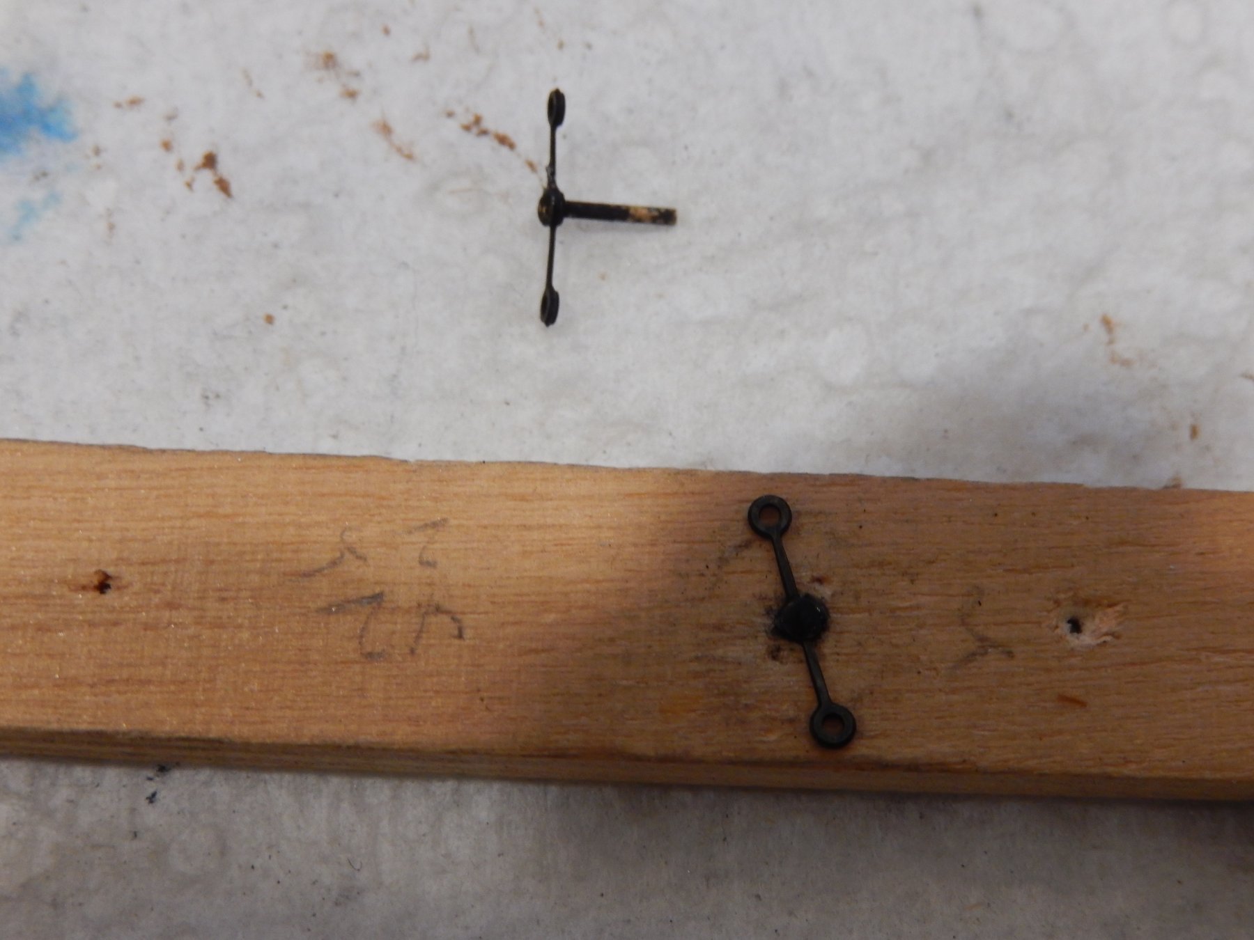
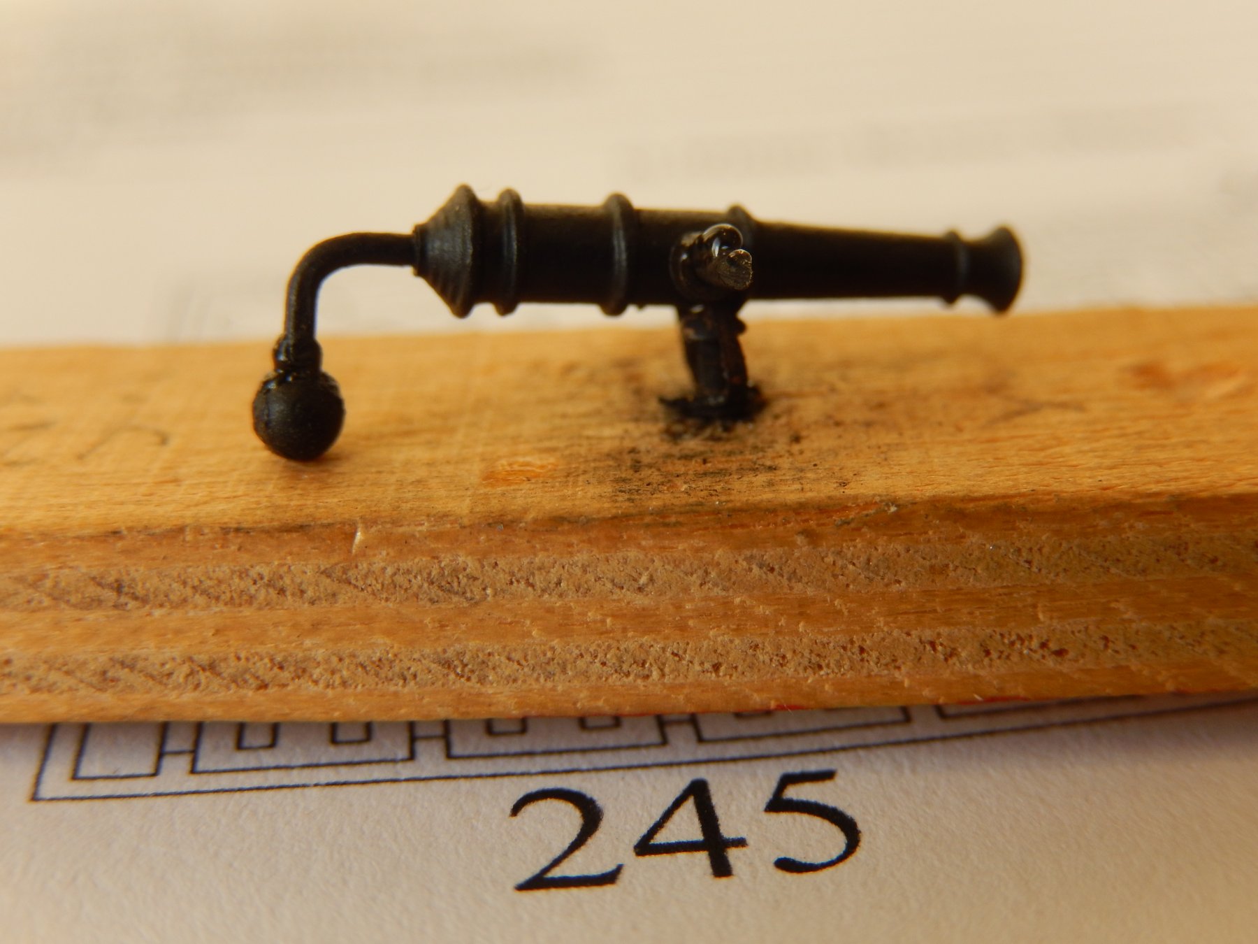
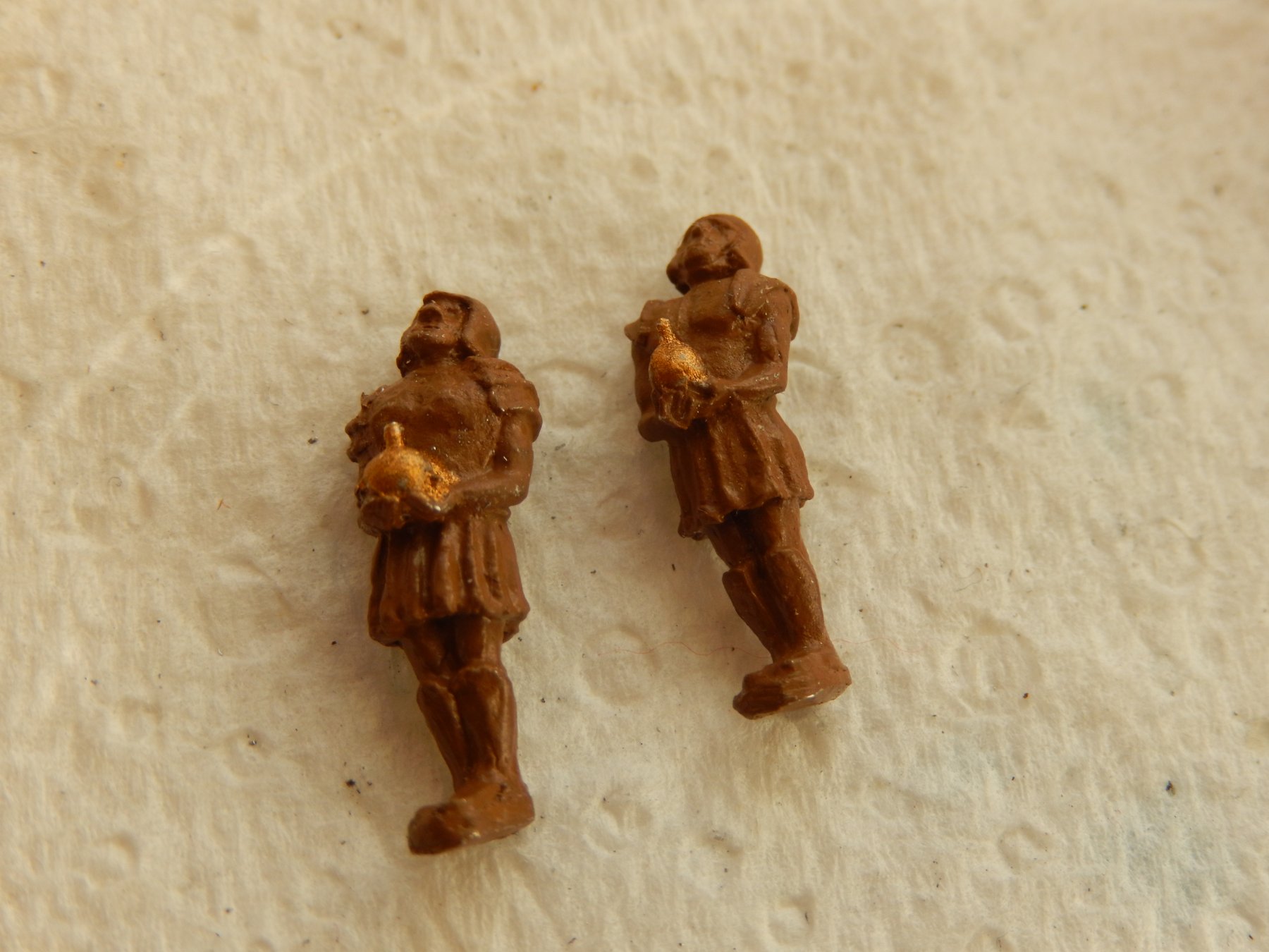
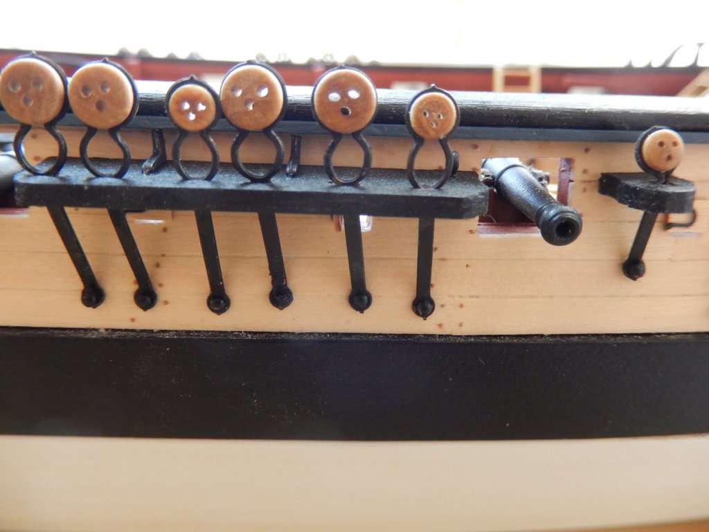
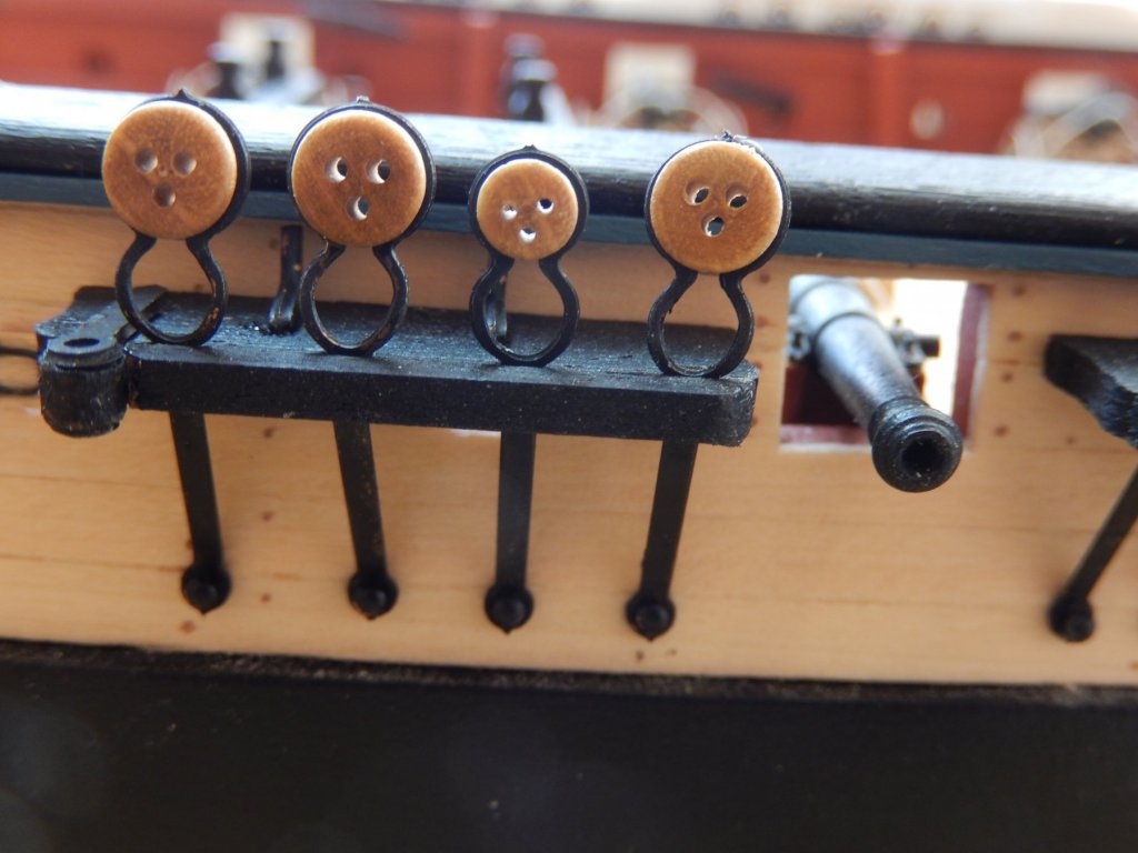
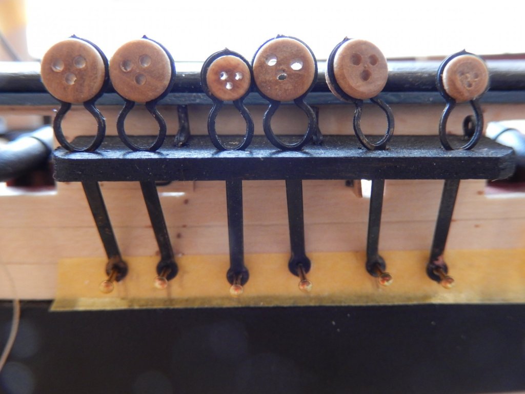
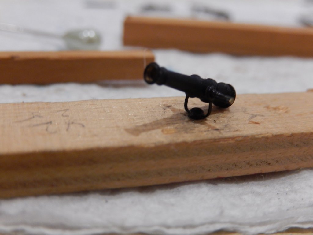
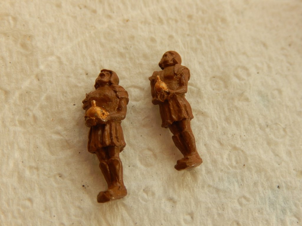
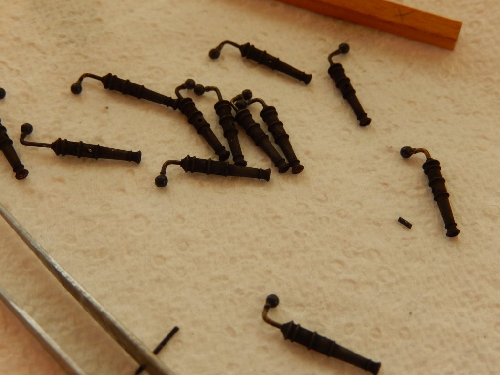
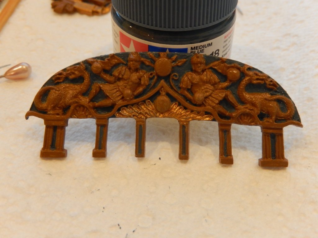
The swivel guns are now finished. Again it's a rather fiddly job. I found the following method worked well. First, drill a nail-diameter hole in a piece of scrap, insert a dome-headed nail into the gun bracket and glue while the assembly is in the hole. This makes the bracket and the nail at right angles to each other. Next, bend the bracket sides up and thread a nail through the bracket holes and the holes provided in the gun (easier said ....). Of course the dome headed nails do not fit in the holes provided in the guns, so the guns need to be drilled out - or if you have some thinner nails as I did, you are indeed fortunate. The brackets shown here are obviously bowed. To fix this, apply pressure on each side of the bracket with a pair of tweezers and to further straighten and make them vertical, hold the assembly down (I used a sturdy pin) and pull the whole assembly up by the nails insert through the bracket holes and gun. All of this was done while the whole lot was located on the hole drilled into the timber scrap. The nail in the following photo had not been cut off - but here is the result. The two little Roman soldiers decorating the quarter have large bases which are quite different to the figures shown in the Anatomy of a Ship. I have taken off almost all the base and will try to mount the figures more closely to that shown in the Anatomy. The figures need touching up, but most of what appears as lack of paint is dust.


- 421 replies
-
- 9
-
-
- caldercraft
- granado
- (and 1 more)
-
Jason - the KK is quite easy to apply. Put a fairly substantial drop on a pin or toothpick, and run it around the edges of the windows. Then draw the pin across the widow and from top to bottom. You may need another drop to cover the hole. It shouldn't be necessary to build it up, but if it is necessary I don't think it would be a problem. I have had no problem with cloudiness, but you must avoid the fumes from CA glue. Once the CA is fully dried (leave it for a day or two) there should be no fumes. While doing my Vanguard I wasn't careful enough, and one window was fogged. I simply cut it out with a craft knife (it's easy) and reapplied. Incidentally PVA has no effect on the KK, so wherever possible it is best to use it.
- 421 replies
-
- 1
-
-
- caldercraft
- granado
- (and 1 more)
-
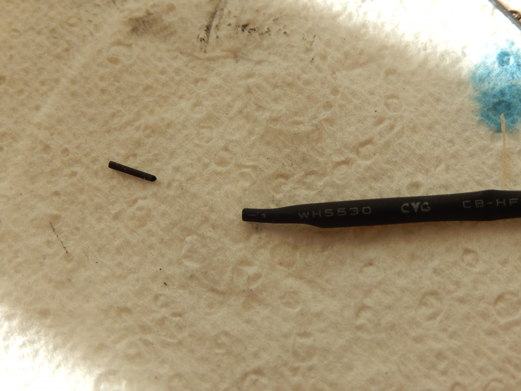
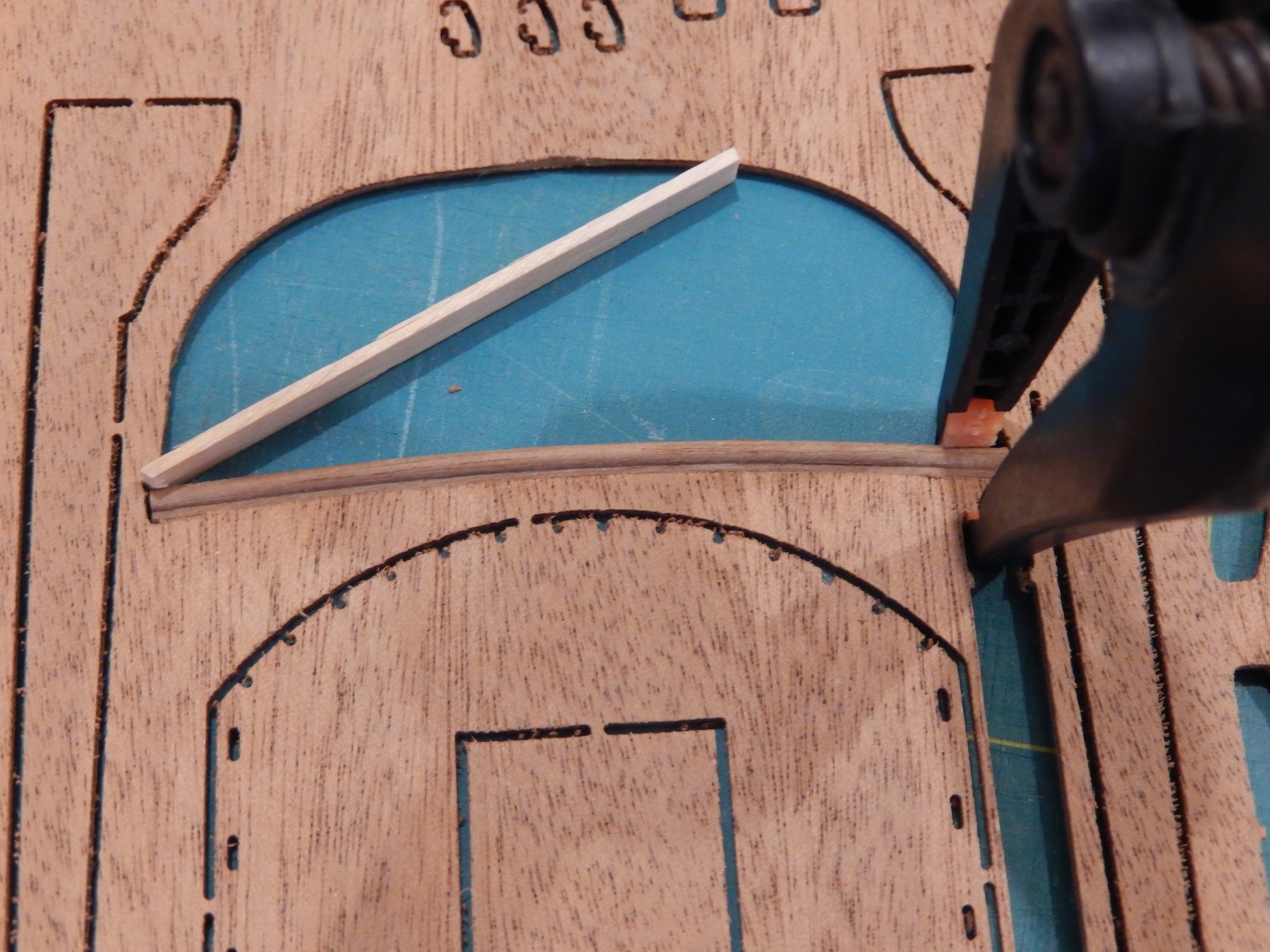
Progress. The lower trim for the transom decorations came out well to my pleasant surprise. In addition to the curvature shown above (the method worked well), there is also a fairly significant curvature of the transom itself. As I noted previously, the trim is reluctant to bend, so in gluing it below the decoration, it was left clamped in position for four days. The opaque parts of the windows shown below is simply Kristak Klear that has not yet completely dried. The cabin light lids are finished. Rather than simply drilling 0.5mm holes for the 'ropes' , I used electrical shrink tubing which I think makes a tidier job. Here is the before and after of the tubing. Apply heat with a hair drier and stretch. Finally I have started on the swivel guns. Putting the nobs on the handles is diabolically difficult (drilling a hole in the nob to receive the handle proved impossible) and the result is both fragile and barely acceptable.


- 421 replies
-
- 8
-
-
- caldercraft
- granado
- (and 1 more)
-
Thanks Jason. Good to see you back. Joe: thanks too. The cheque would probably have bounced anyway.
-
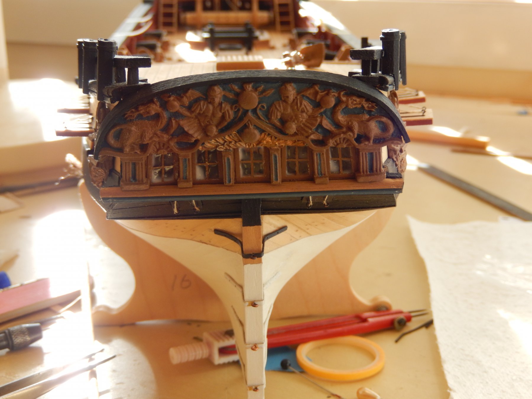
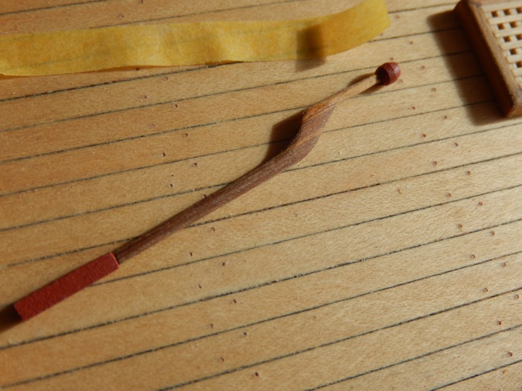
Progress is slow as there are others things that must be done. The transom decorations are now mounted. The Kristal Klear will be put on the widows when the lower trim is attached. This is how it looks at the moment. The instructions suggest the taffrail is mounted after the decoration. I suggest the contrary. The decoration needed minor trimming to fit. Doing it in situ would have difficult. Fitting it with the taffrail in place enabled close fit which in the flesh looks close to perfect, though I see in the (considerably enlarged) photo a couple of tiny gaps to be closed. The lower (finishing) trim is supposed to be brass rod. I am trying the same profile timber I used along the sides. This entails bending the timber to fit the curvature - something it is reluctant to do. Having given it a good soak in boiling water, it has been wedged in the cutout for the transom. I am hoping that after a few days under stress it will fit. If it doesn't, there is always the brass. Finally, I wasn't too happy with the brass rod specified in the instructions for the tiller. I had seen Joe V's tiller and 'appropriated' his idea. (The cheque is in the mail.) It needs a coat of polyurethane, but it should turn out acceptably.


- 421 replies
-
- 12
-
-
- caldercraft
- granado
- (and 1 more)
-
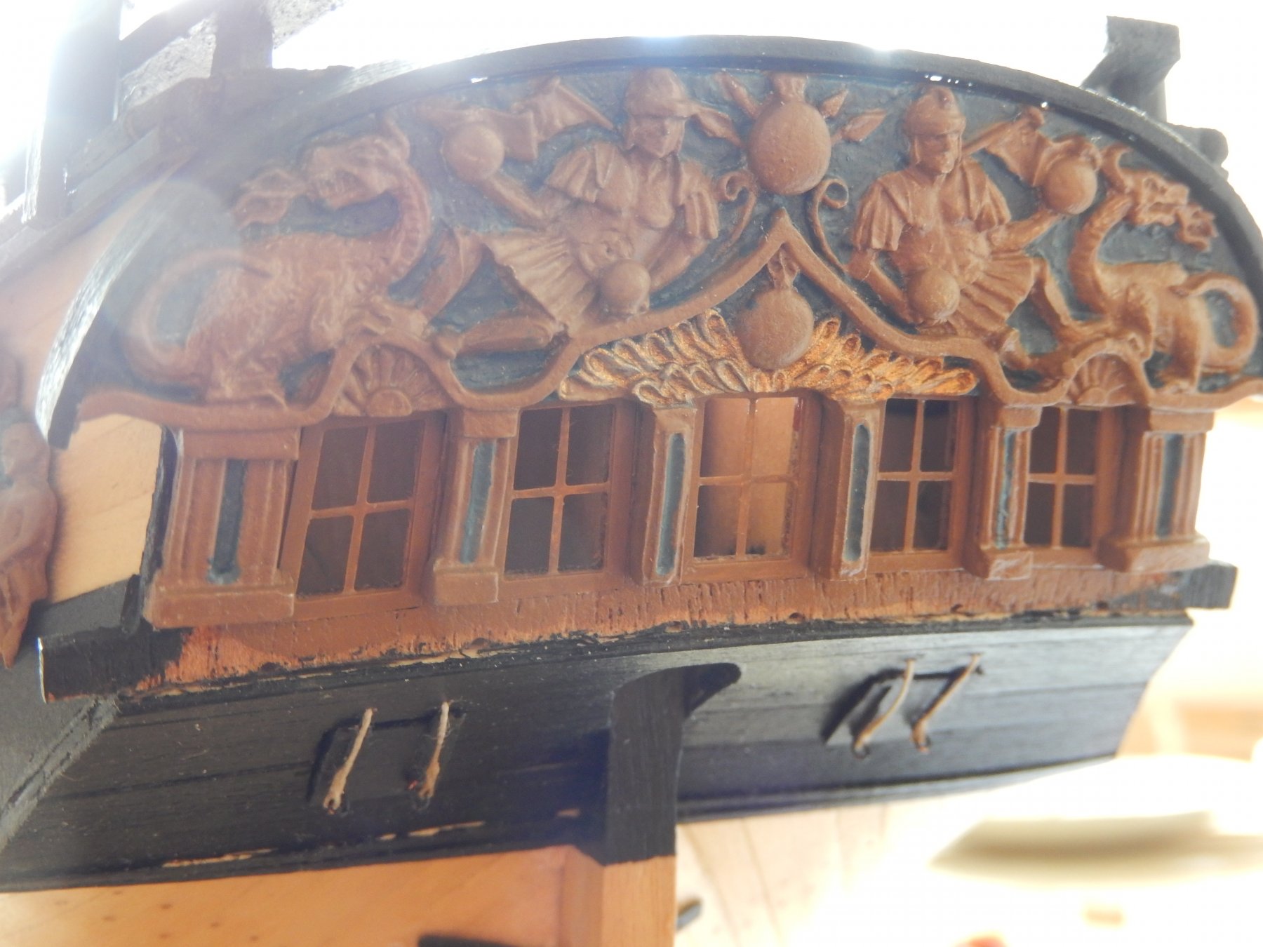
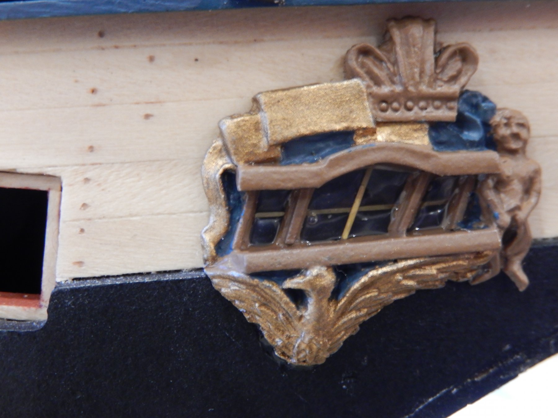
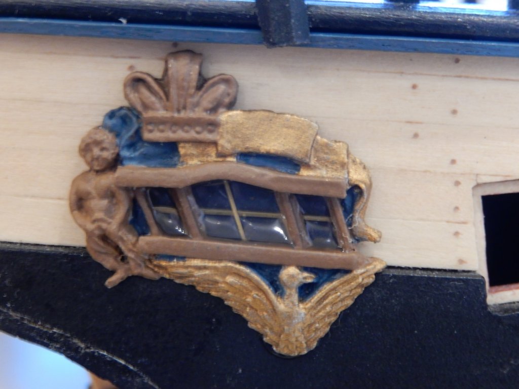
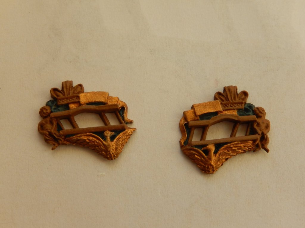
The side decorations are now on. One of the advantages of taking ultra-closeups is that they highlight any mistakes which, with luck, may then be rectified. Both the decorations in the flesh look fine. Under magnification - well, you can see the slips of the paint brush. I shall do some touching-up. Incidentally, the windows are in fact quite clear (I've used Kristal Klear). The areas that appear clouded are reflections. Here is the stern decoration. Again reflections are misleading; there are no missing paint spots, though there is some minor touching-up to be done.

- 421 replies
-
- 11
-
-
- caldercraft
- granado
- (and 1 more)
-
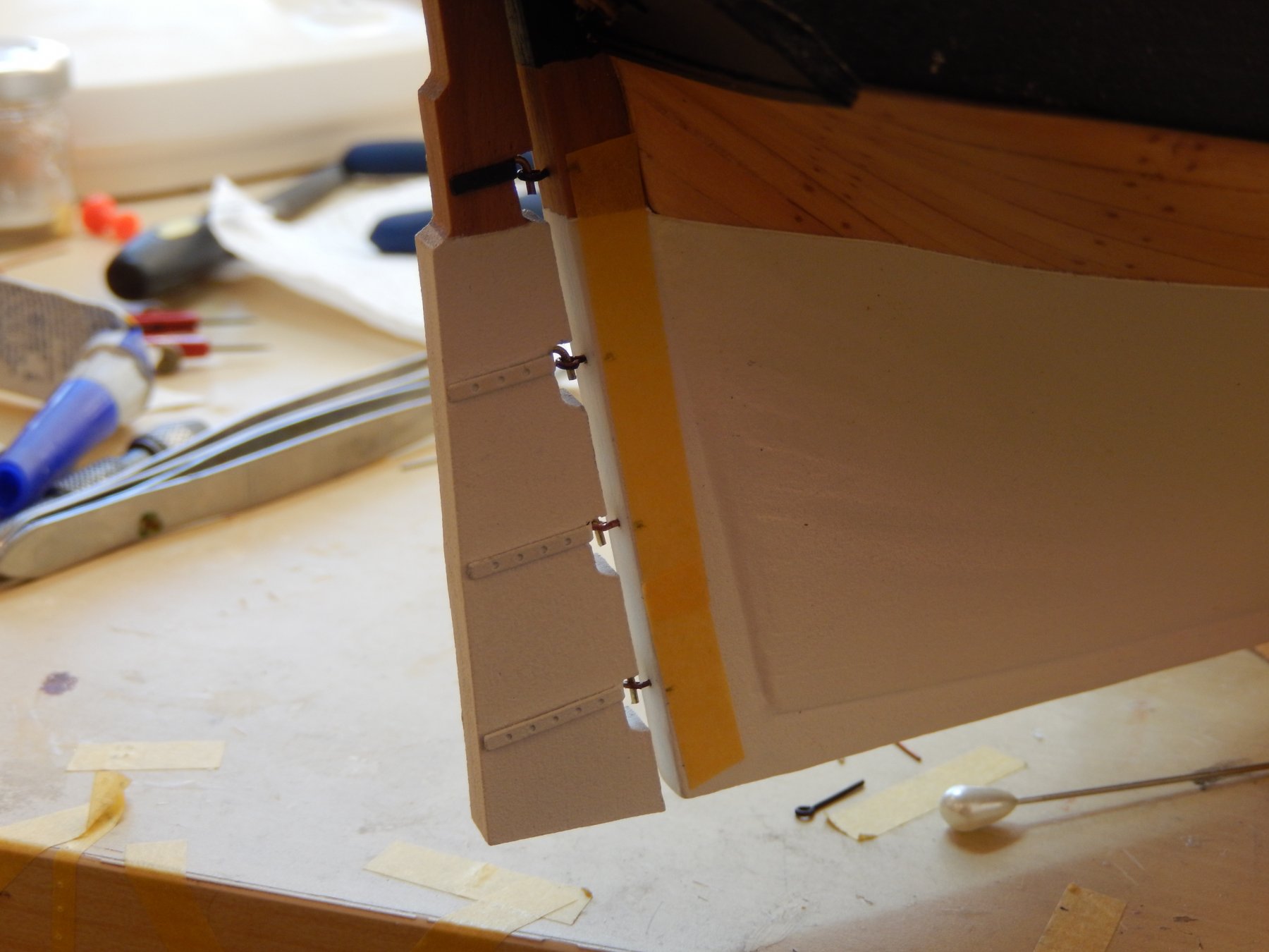
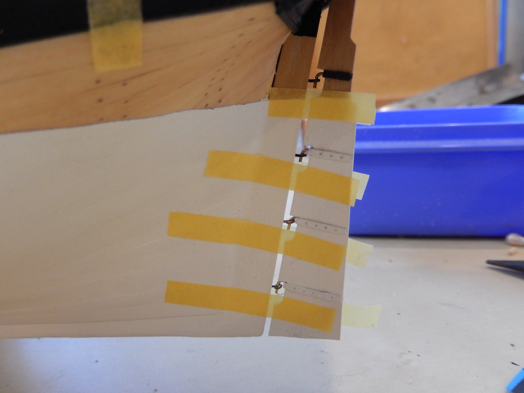
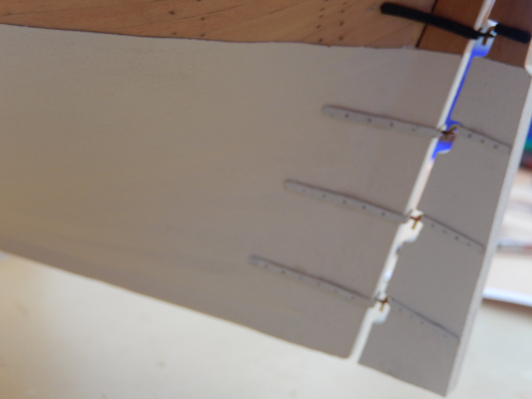
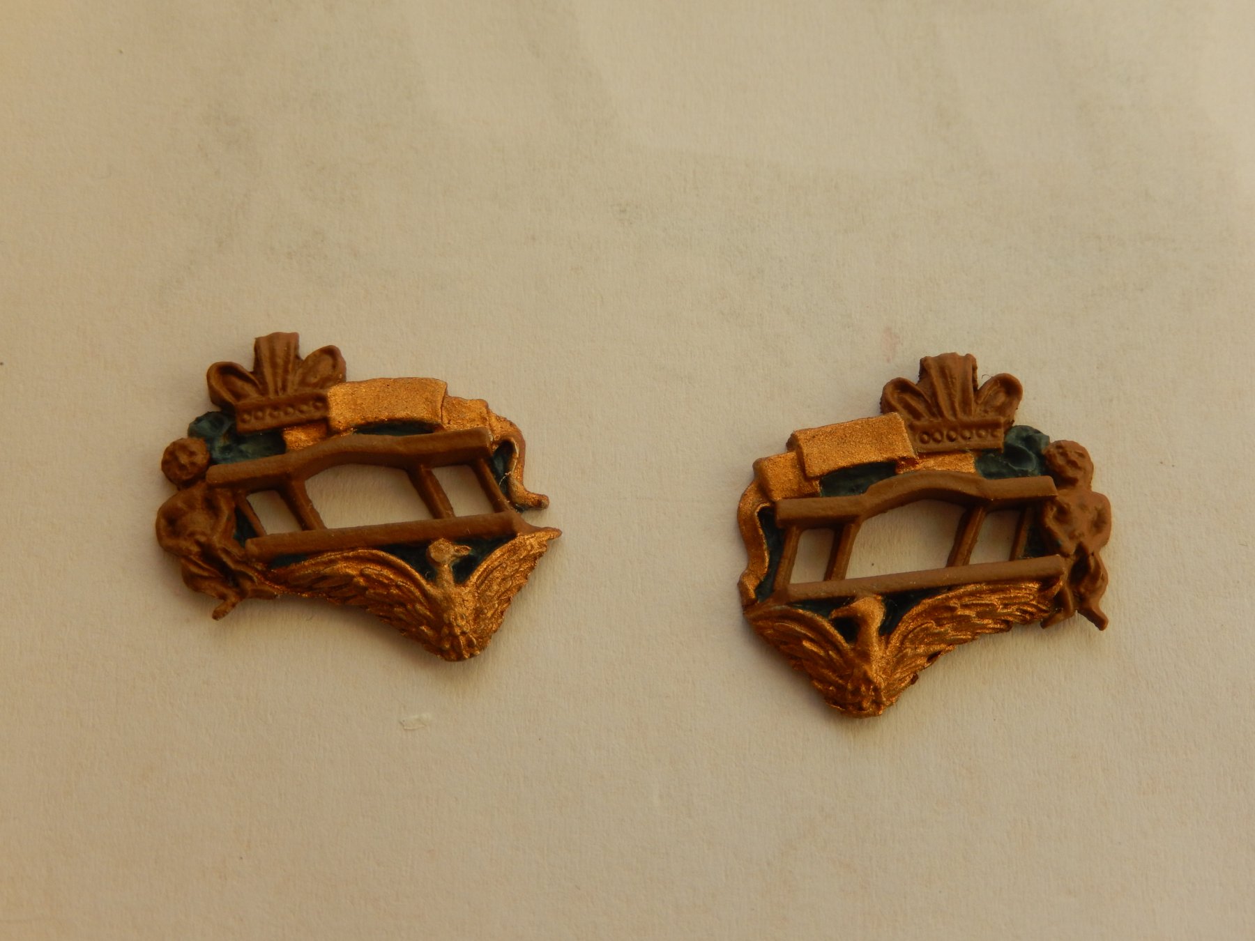
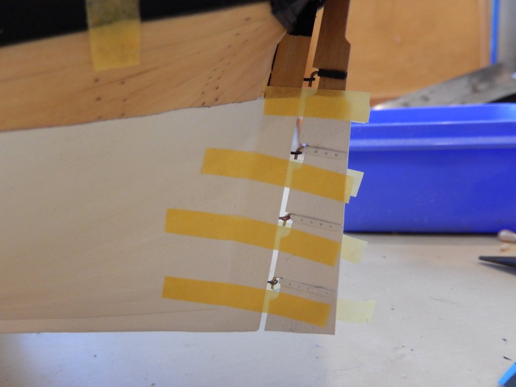
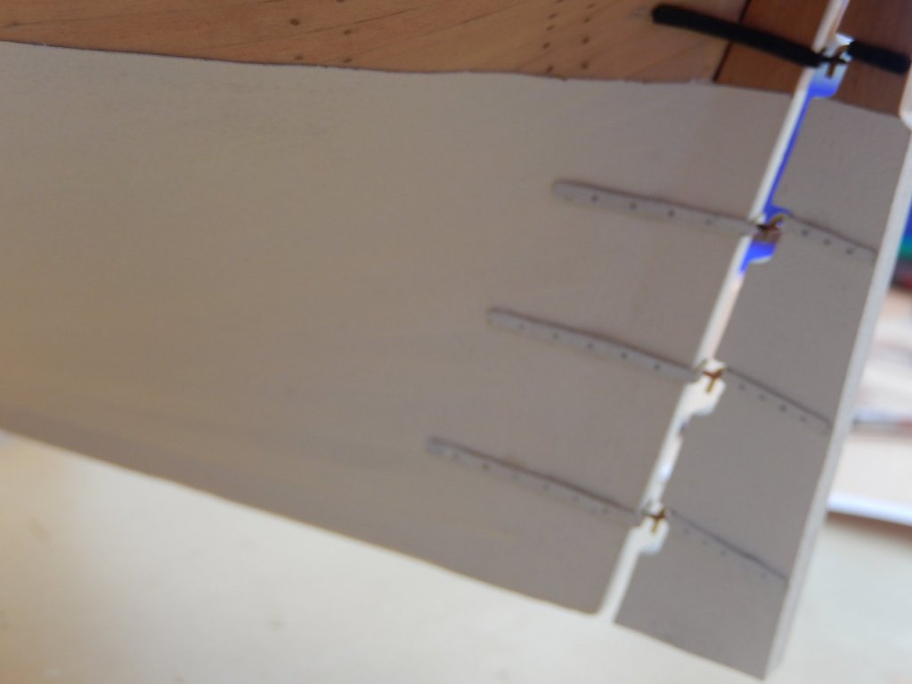
The rudder is an awkward little project. Here are the steps others may find useful. First the rudder was mounted on a piece of strip to keep it in position, and the positions of the gudgeons marked on tape. Once the gudgeons were fitted, the rudder was mounted. Tape was then used as a guide for the straps. While some of this was going on, the side decorations were completed. It's unfortunate that there is no record of the correct colours, and it is certainly highly unlikely that my colours are remotely accurate. However the bronze at least is closer to the colour of the mythical phoenix than white. Anyway, I thought I would use a little more of the bronze paint to prevent it going to waste. This photo shows up every little imperfection. In the flesh, they look quite good.

- 421 replies
-
- 13
-
-
- caldercraft
- granado
- (and 1 more)
-
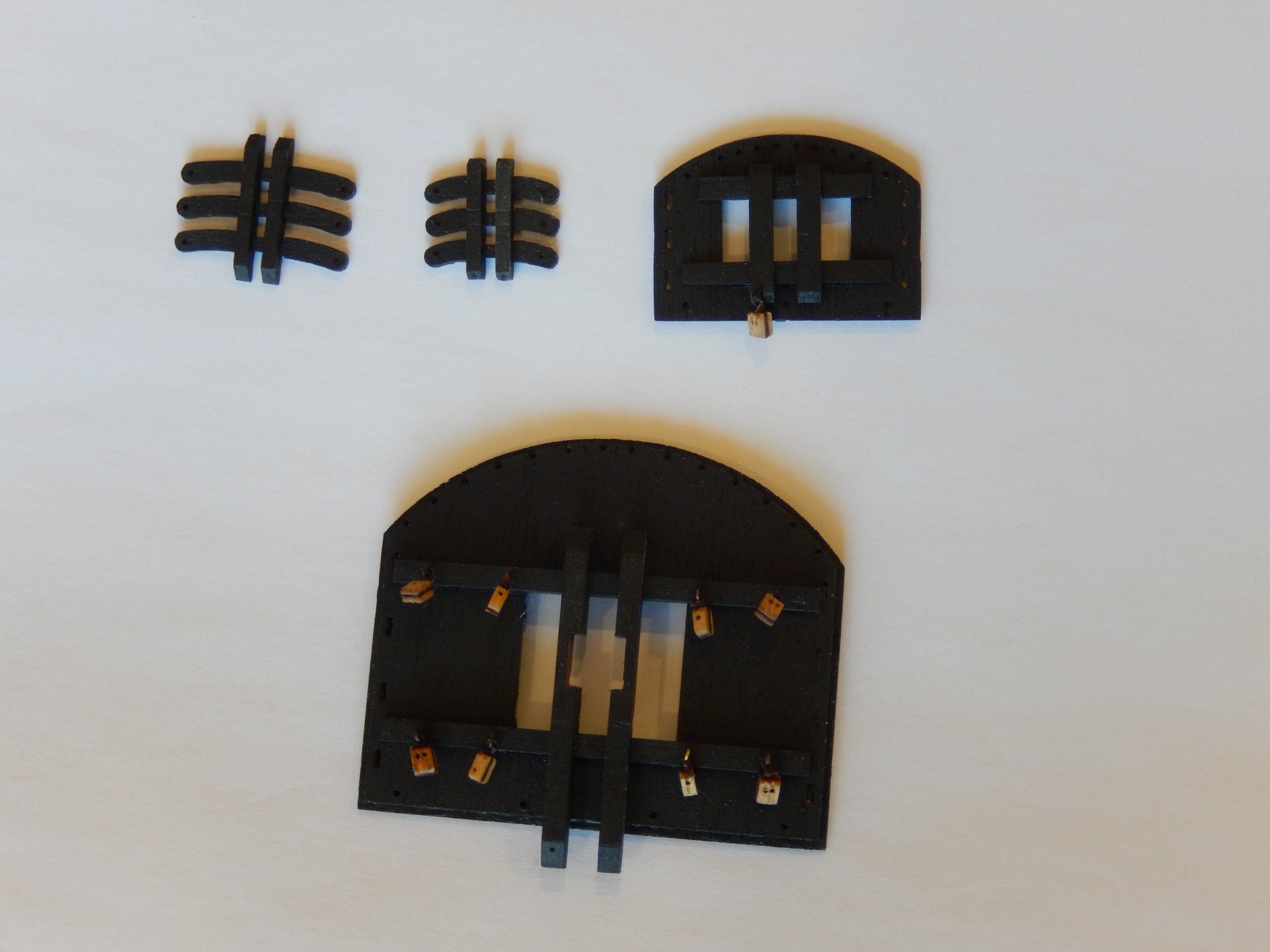
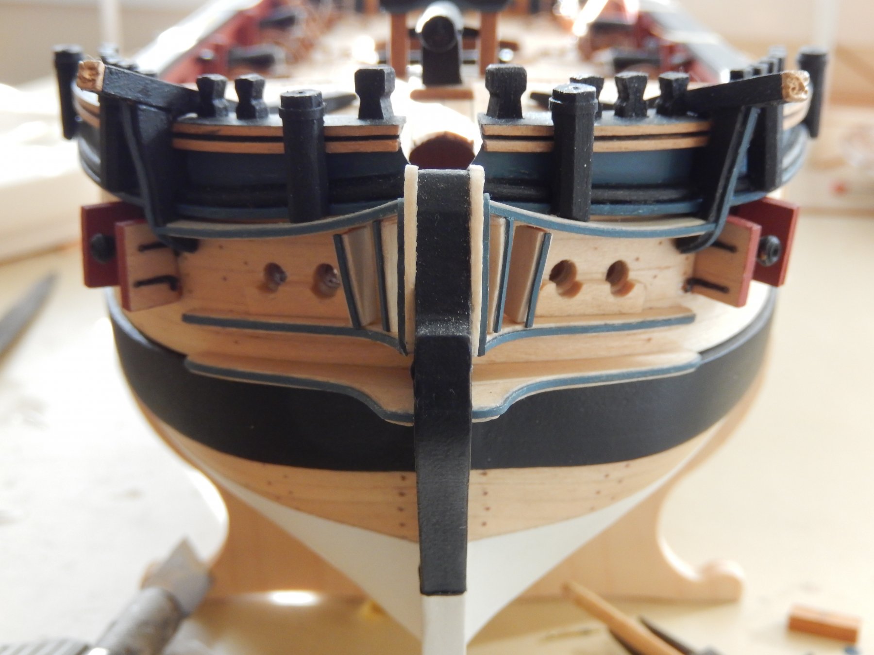
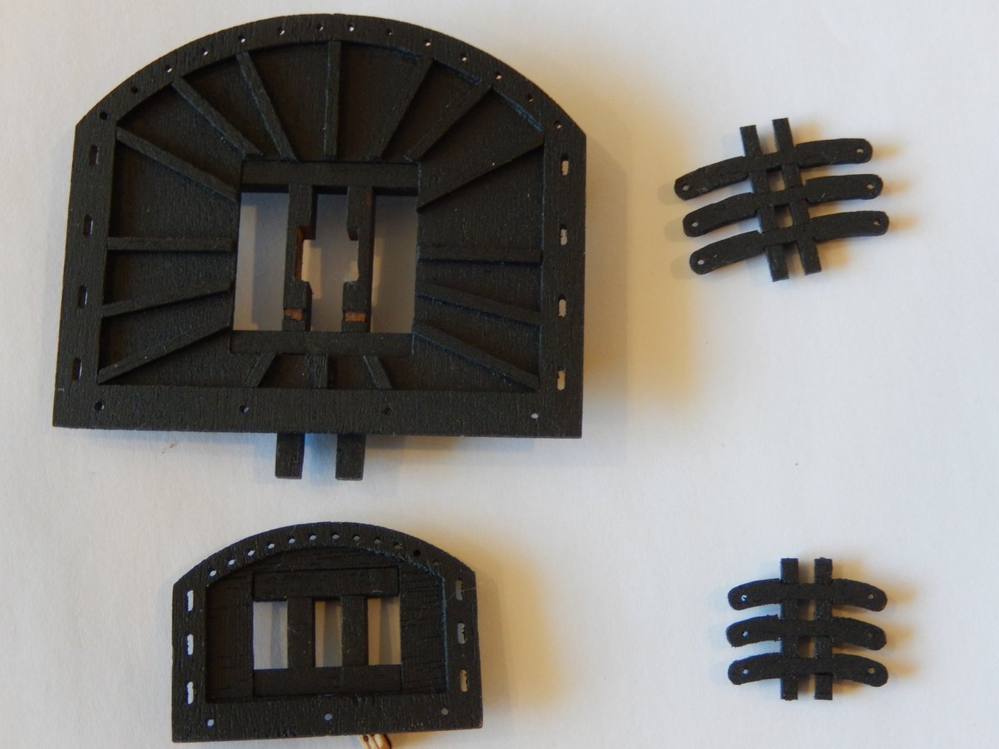
While watching paint dry, I have finally completed the bow fittings, now including the gun doors. Applying the hinges and then attaching the doors ended up testing my vocabulary. They came out reasonably well but as usual there is some touching-up to do.


- 421 replies
-
- 10
-
-
- caldercraft
- granado
- (and 1 more)
-
Hi Eralex. I had already noted that. I will finish the painting before installing them.