Stuntflyer
-
Posts
1,126 -
Joined
-
Last visited


.thumb.jpeg.fc5d633a7b34428fcf19419a73d56d55.jpeg)


-
 Stuntflyer reacted to a post in a topic:
Sloop Speedwell by Chuck - Ketch Rigged Sloop, 1752 - POF
Stuntflyer reacted to a post in a topic:
Sloop Speedwell by Chuck - Ketch Rigged Sloop, 1752 - POF
-
JeffT reacted to a post in a topic:
Sloop Speedwell 1752 by JeffT - Syren Ship Model Company - 1:32 scale - POF Sloop
-
 Ditto! Very nice start. Looking forward to seeing your progress.
 -
Stuntflyer reacted to a post in a topic:
HM Cutter Cheerful 1806 by Erik W - 1:48 scale
-
Stuntflyer reacted to a post in a topic:
HM Cutter Cheerful 1806 by Erik W - 1:48 scale
-
Chuck reacted to a post in a topic:
Sloop Speedwell 1752 by Rustyj - Syren Ship Model Company - 1:32 Scale - POF Sloop
-
Yup! That's the way to do it. Very nice result, Rusty!
-
Stuntflyer reacted to a post in a topic:
Sloop Speedwell 1752 by Rustyj - Syren Ship Model Company - 1:32 Scale - POF Sloop
-
Ryland Craze reacted to a post in a topic:
Sloop Speedwell by Chuck - Ketch Rigged Sloop, 1752 - POF
-
Stuntflyer reacted to a post in a topic:
Sloop Speedwell by Chuck - Ketch Rigged Sloop, 1752 - POF
-
mtaylor reacted to a post in a topic:
Sloop Speedwell by Chuck - Ketch Rigged Sloop, 1752 - POF
-
CiscoH reacted to a post in a topic:
The Hayling Hoy by jpalmer1970 - 1:48 scale - First POF build
-
Stuntflyer reacted to a post in a topic:
Sloop Speedwell 1752 by sfotinos - Syren Ship Model Company - 1:32 Scale - POF Sloop
-
Stuntflyer reacted to a post in a topic:
Sloop Speedwell by Chuck - Ketch Rigged Sloop, 1752 - POF
-
druxey reacted to a post in a topic:
The Hayling Hoy by jpalmer1970 - 1:48 scale - First POF build
-
Erik W reacted to a post in a topic:
Sloop Speedwell by Chuck - Ketch Rigged Sloop, 1752 - POF
-
Jack12477 reacted to a post in a topic:
Sloop Speedwell by Chuck - Ketch Rigged Sloop, 1752 - POF
-
So nice, Chuck. Everything seems to be fitting together as planned. However, I know that there where several iterations in design to get there.
- 780 replies
-
- 4
-
-
- speedwell
- syren speedwell
- (and 1 more)
-
Stuntflyer reacted to a post in a topic:
Sloop Speedwell by Chuck - Ketch Rigged Sloop, 1752 - POF
-
Stuntflyer reacted to a post in a topic:
Sloop Speedwell by Chuck - Ketch Rigged Sloop, 1752 - POF
-
Ryland Craze reacted to a post in a topic:
Sloop Speedwell 1752 by Rustyj - Syren Ship Model Company - 1:32 Scale - POF Sloop
-
Stuntflyer reacted to a post in a topic:
Sloop Speedwell 1752 by Rustyj - Syren Ship Model Company - 1:32 Scale - POF Sloop
-
mtaylor reacted to a post in a topic:
The Hayling Hoy by jpalmer1970 - 1:48 scale - First POF build
-
Rusty, great to see your building Speedwell. Looking forward to seeing your progress. Rick, I think Rusty already put 2-1"x2" boards lengthwise.
-
Chuck and I like to use a number 2B pencil on one edge of the joined surfaces. It leaves a strong glue joint and a clean line once sanded out.
-
Nice start, Steve. Keep up the good work. No hurry, we'll be following.
-
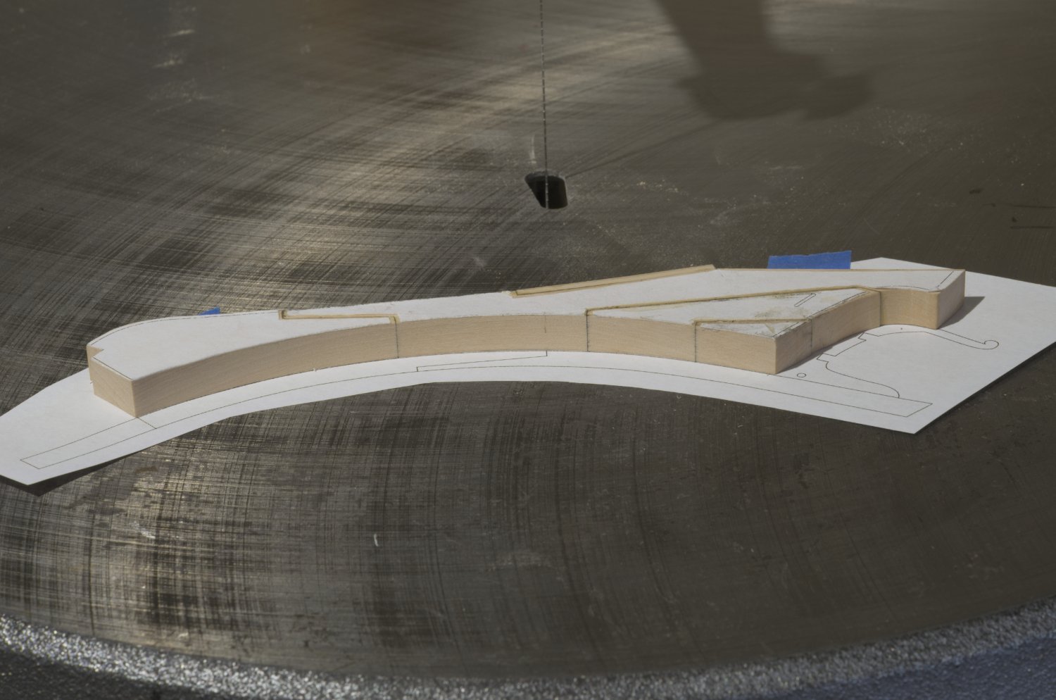
I like to use paper templates held down with acid free rubber cement or even Elmer's School glue. I have always found that it's better to leave a little wiggle room when cutting the outline. In certain cases, rather than shaping each section individually, I just cut the joints accurately and then join the various sections together. After doing that it's easier to get a more accurate outline of the joined parts while the templates are still attached. I'm not suggesting that you would do that with the stem and keel pieces. Just something that you might consider doing in the future. Here is an example of this from my Speedwell build. Mike

- 24 replies
-
- 10
-
-
Shawn, You're good to go. I'm looking forward to seeing your build log. Mike
- 780 replies
-
- 5
-
-
- speedwell
- syren speedwell
- (and 1 more)
-
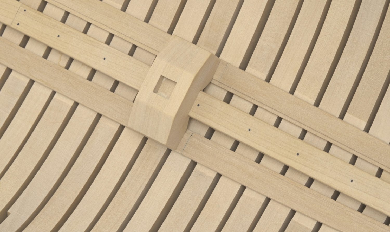
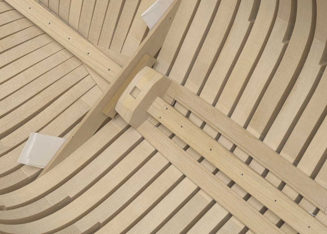
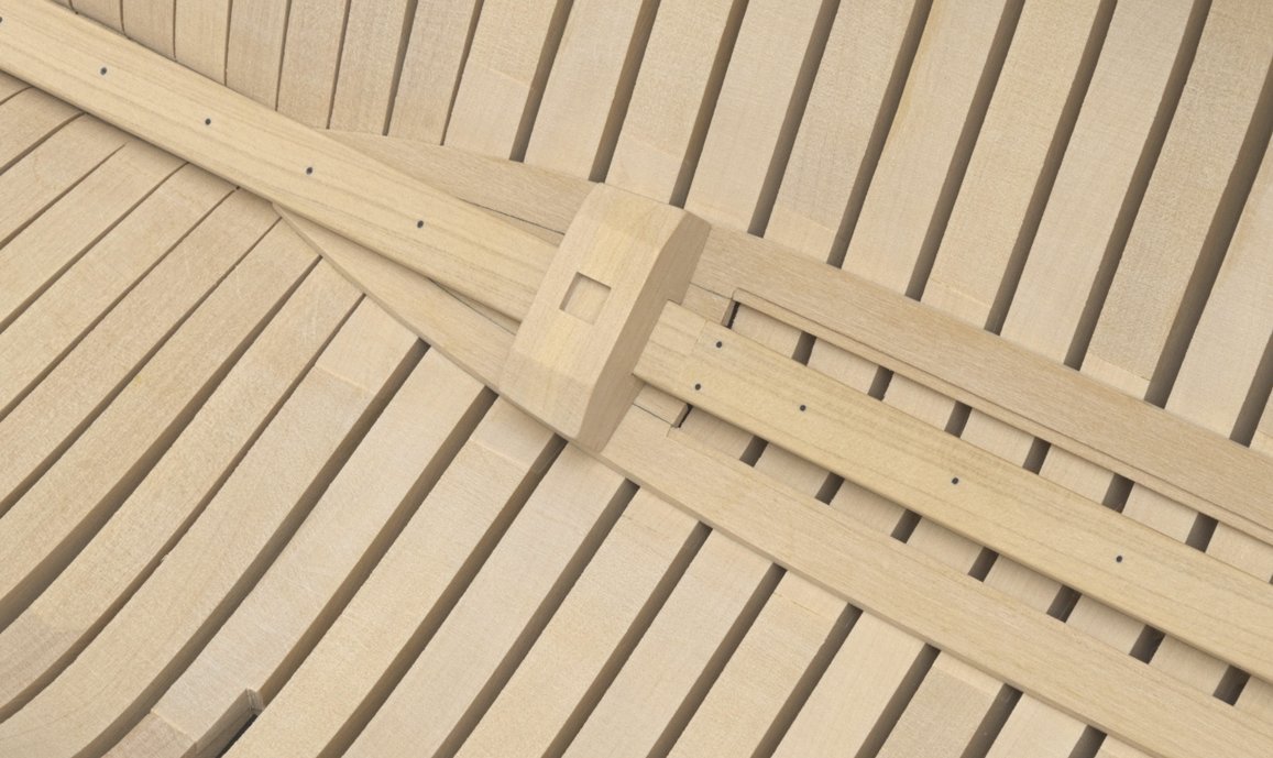
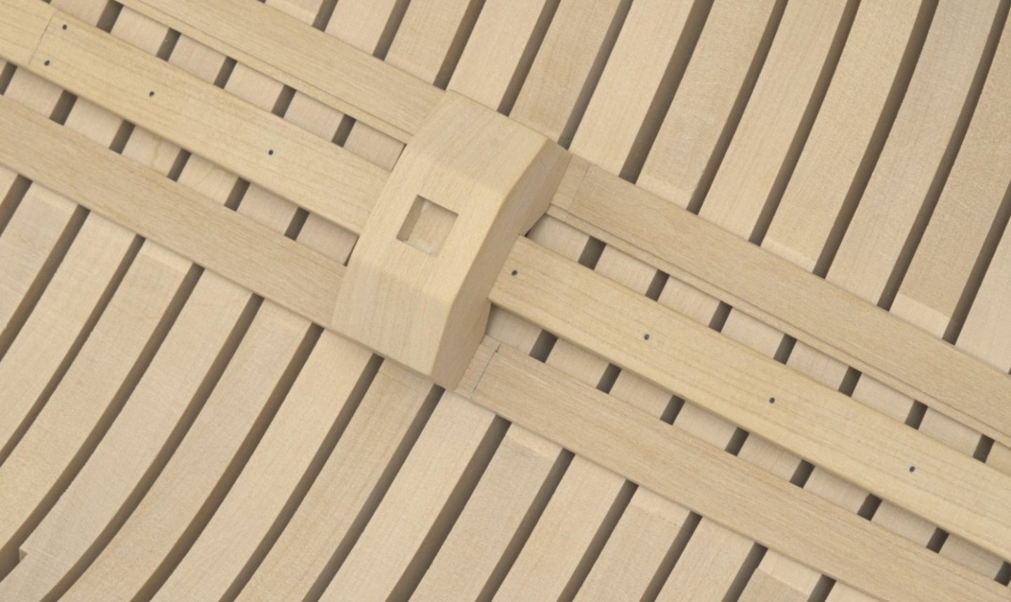
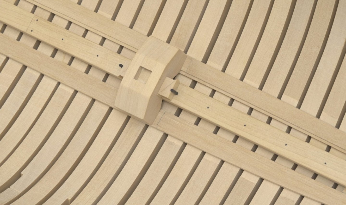
Mast steps Over the weekend I completed the two mast steps. The location of these is very important and the plans really helped me out here. Mizzen step: The first thing I did was to tack glue the three sections together with a spot or two of school glue. Then I milled the notch which goes over the keelson. After breaking the pieces apart, I milled the notch into the top of the middle piece and glued the aft and middle sections together permanently. Next, I angled the bottom edge about 5° to account for the upward sweep of the keelson. I worked the two sections until everything was sitting flush with the limber strakes and keelson. The fore section was then positioned over the keelson, against the first two pieces, and shaped accordingly. You might be asking, why didn't I just glue all three pieces together from the start? It wasn't long before I realized that the shape of the fore and aft pieces were not Identical. The aft piece had a slightly different angle at the foot than the fore piece. This is due to the twist in the limber strake, I think. Doing this in stages allowed me to get each piece angled correctly without the hassle of trying to work the whole piece at once. According to the plan, the center of the mizzen step sits .151" (approx 5/32") in front of the aft edge of frame 11F. I glued the step into position using a cross piece and shim to account for that distance. This also helped to get the step perpendicular to the keel. Main step: This was made basically the same way as the mizzen step. It sits over frame Ba. Unlike the mizzen step, I didn't need to taper the foot. The distance between the centers of the two steps is approx 9-5/32". For the pins I turned down a 1/16" dowel using the Dremel tool. They are press fitted without the need for glue. I've had so much fun making these that I almost forgot that I need to finish up the outer hull planking.😏 Mike
-
I remember the feeling. Nicely done!
-
Yeah, there is no way to push the eye bolt into boxwood. Fwiw, I use a rat tail needle file to make the groove, channel or notch for lack of a better word. I don't push and pull the file. Rather, I push the file down into the hole, holding it down with my finger at an angle and turn it.
-
Thanks, Chuck!
-
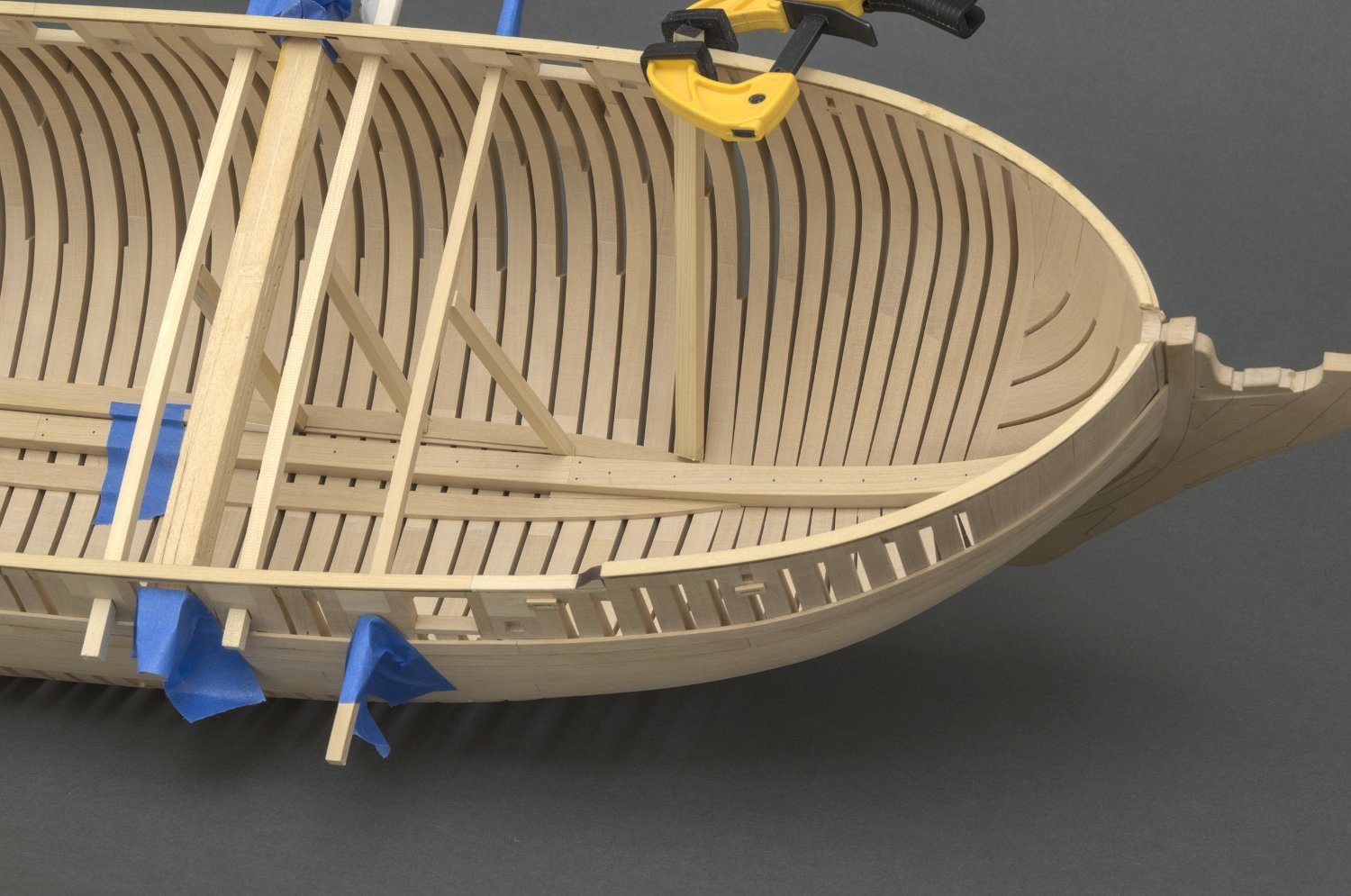
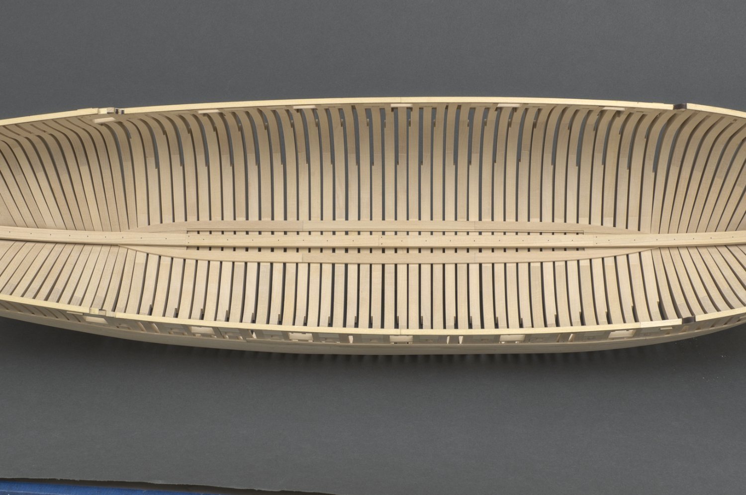
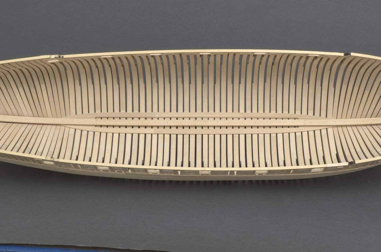
Limber strakes I guess these strakes are for the most part hidden. Still, having never made them before I decided to give these a try. I used the plan drawings as usual for the templates. Rather than shape them exactly to the template, I left some wiggle room in case adjustments where needed. The rabbet on the inside edge was cut with a simple scraper made from a hacksaw blade. After adding the center section, I proceeded to add the fore and aft sections while trying to maintain as smooth a run along the outer edge of the strakes as possible. Both the aft and fore sections have a twist which needs to be taken into account one way or another. I was able to twist the aft section with wet heat and hold it in position while the slow drying CA set. I couldn't get enough twist in the fore section. If these were made from AYC rather than boxwood, it wouldn't have been a problem. Rather than torture myself, I went with some very expensive and exotic tools in order to give me a helping hand. Mike

-
Drawing center lines
Stuntflyer replied to Stuntflyer's topic in Modeling tools and Workshop Equipment
Thanks everyone, Issue solved! I can make a miniature version of the Pioneer marking gauge.