Kris Avonts
-
Posts
92 -
Joined
-
Last visited


-
 Mike Y reacted to a post in a topic:
Adding a cheap DRO to a Proxxon XY-table
Mike Y reacted to a post in a topic:
Adding a cheap DRO to a Proxxon XY-table
-
CDR_Ret reacted to a post in a topic:
Adding a cheap DRO to a Proxxon XY-table
-
jim Landis reacted to a post in a topic:
Adding a cheap DRO to a Proxxon XY-table
-
mtaylor reacted to a post in a topic:
Adding a cheap DRO to a Proxxon XY-table
-
Adding a cheap DRO to a Proxxon XY-table
Kris Avonts replied to Kris Avonts's topic in Modeling tools and Workshop Equipment
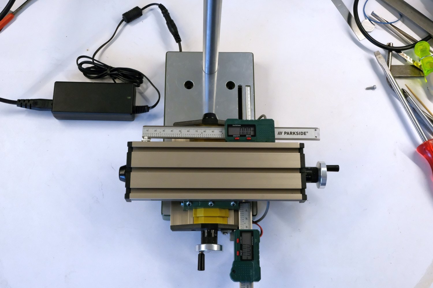
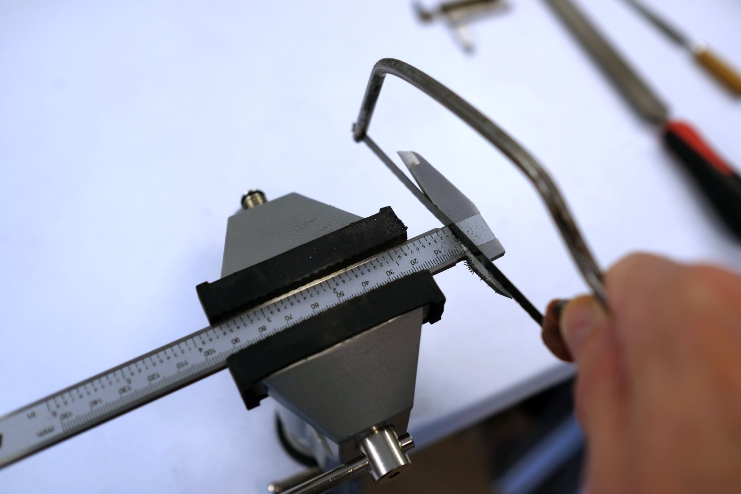
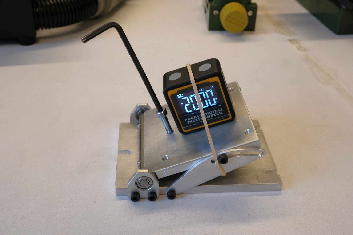
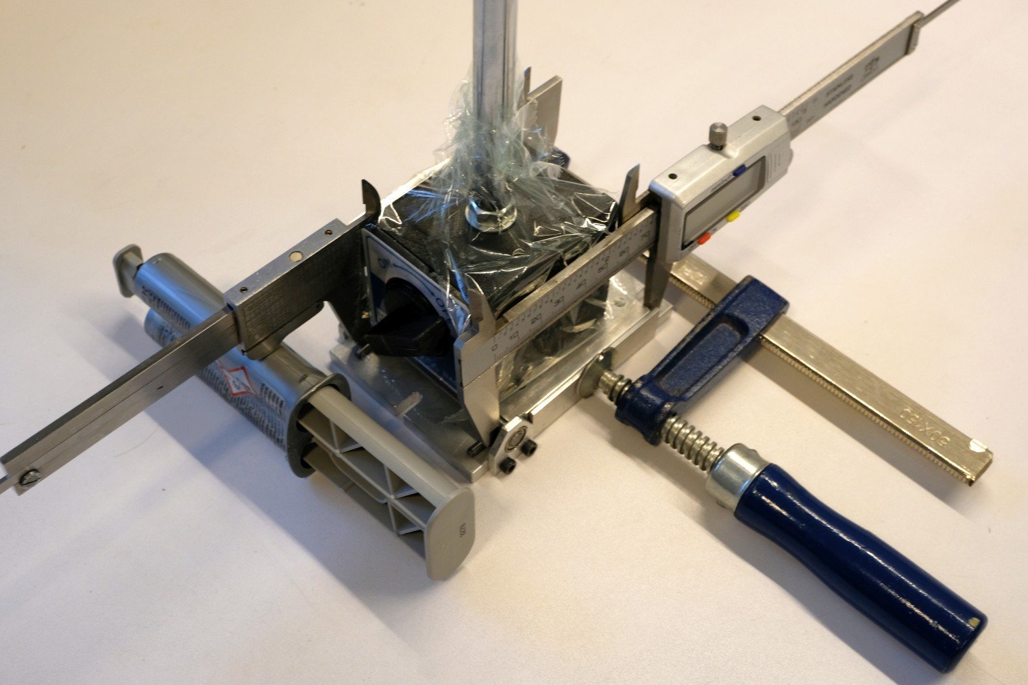
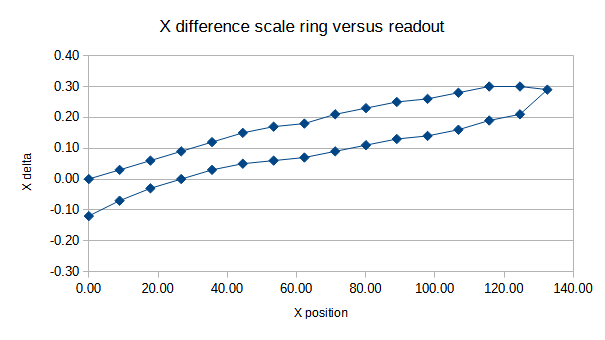
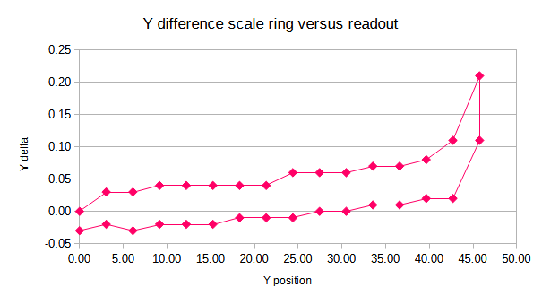
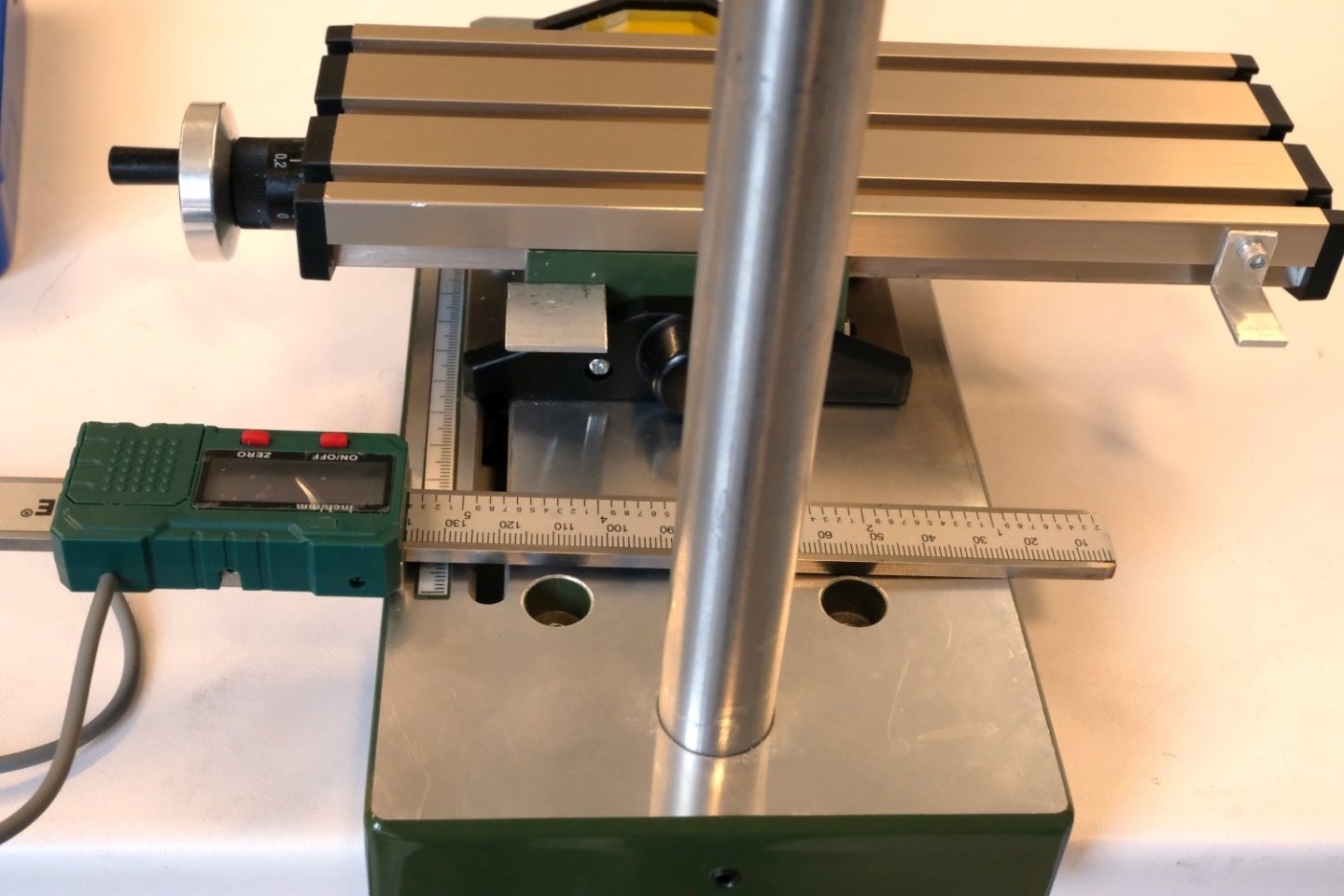
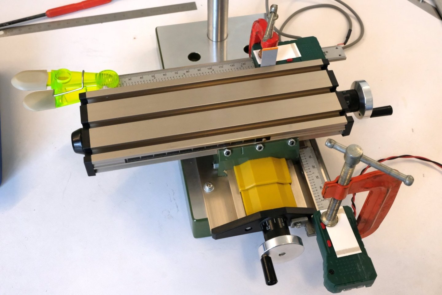
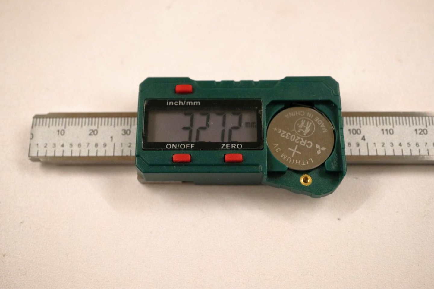
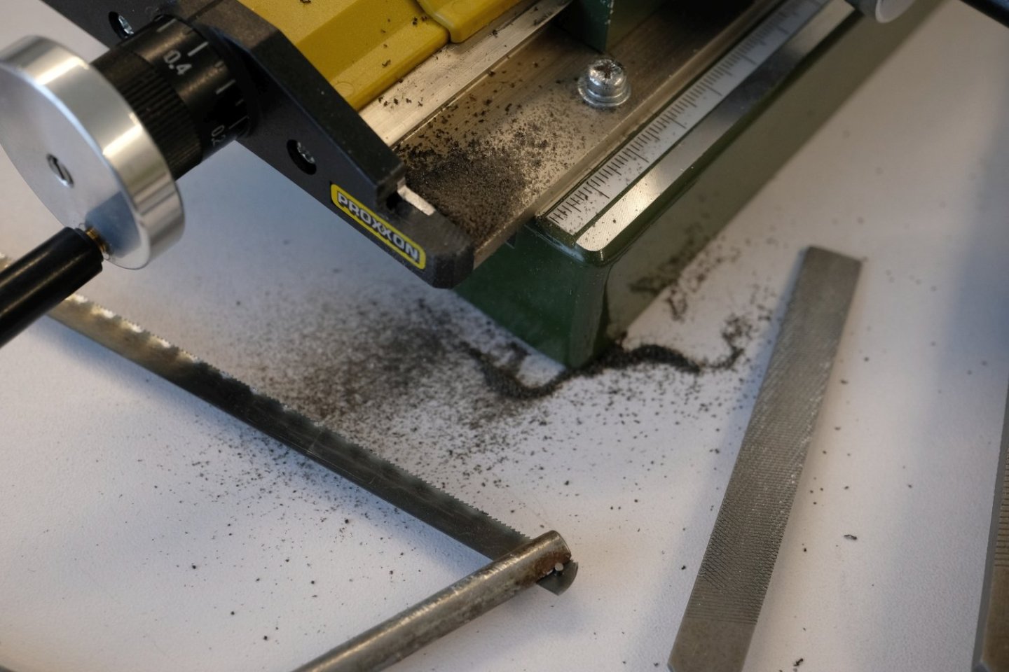
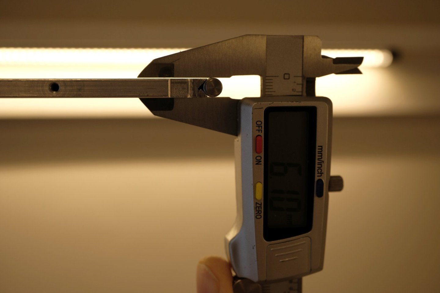
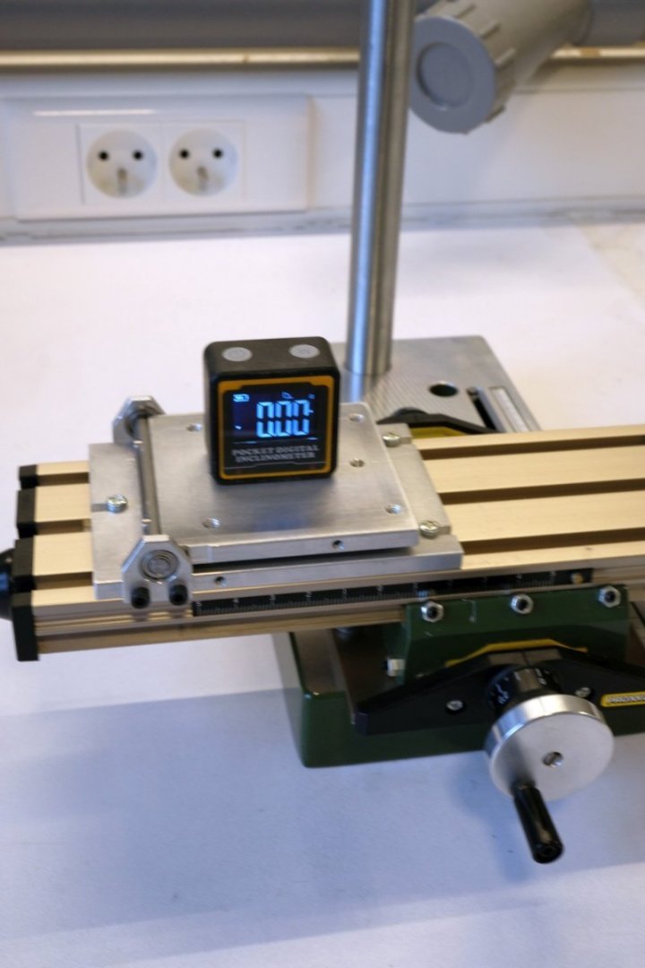
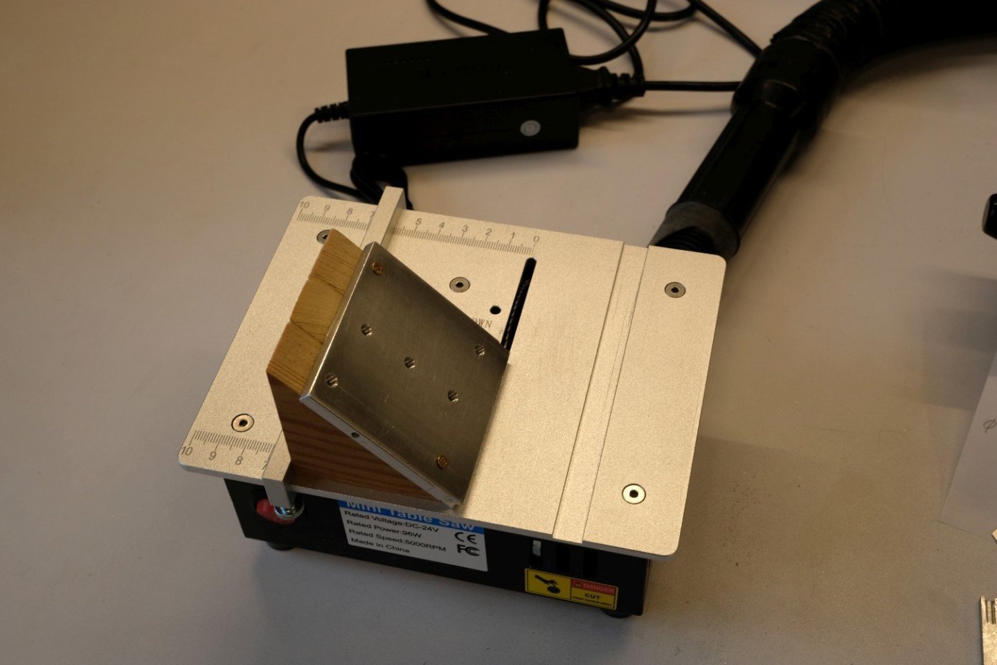
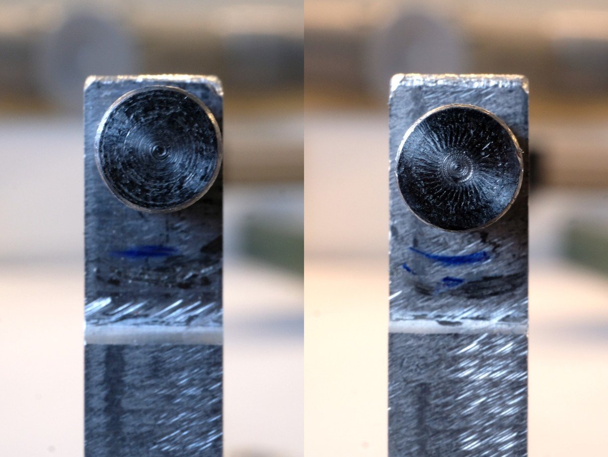
Hello, It’s time for some evaluation of this modified proxxon KT 70. As a test I made a setup to use the xy-table over its whole range with fixed steps in both x and y direction. In x it was 8.9 mm step and in y 3.1 mm. That way the whole range is covert with 15 steps. I use the scale ring to make the steps and note the DRO display values. Here you see the setup with a camera positioned to show the readings. This is how the table is stepped from bottom-right to top-left. I also did the inverse movement from top-left to bottom-right and again noted all displayed values. When entering the values in a spreadsheet and plotting things you get the following results. You can see that the curves are not ‘flat’ and that moving up and down follow a different path. Not flat means that the pitch of the xy-table is slightly off its nominal 1 mm. In the x direction we have about 0.3 mm error after 120 mm and that can be explained with a pitch being 0.9975 mm. For the y direction it is about the same result, a pitch of 0.9980. The different paths are a result from backlash, that is ‘play’ between nut and screw. For both x and y it is about 0.1 mm. I assume the DRO is correct and has no play. To be sure I also checked a small movement (8 mm) in the x direction somewhat in the middle of its range with a dial indicator. The result is shown next. The dial indicator and the readout give almost identical values. Ok, then I trust the DRO from now on. It is convenient because it keeps track of the millimetres already moved and it eliminates the backlash error. That is it for now, hope you liked it. Best regards, Kris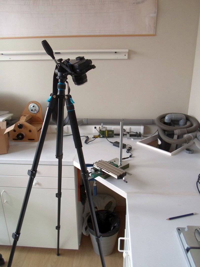
-
wefalck reacted to a post in a topic:
Adding a cheap DRO to a Proxxon XY-table
-
wefalck reacted to a post in a topic:
Adding a cheap DRO to a Proxxon XY-table
-
Mike Y reacted to a post in a topic:
Adding a cheap DRO to a Proxxon XY-table
-
mtaylor reacted to a post in a topic:
Adding a cheap DRO to a Proxxon XY-table
-
Adding a cheap DRO to a Proxxon XY-table
Kris Avonts replied to Kris Avonts's topic in Modeling tools and Workshop Equipment
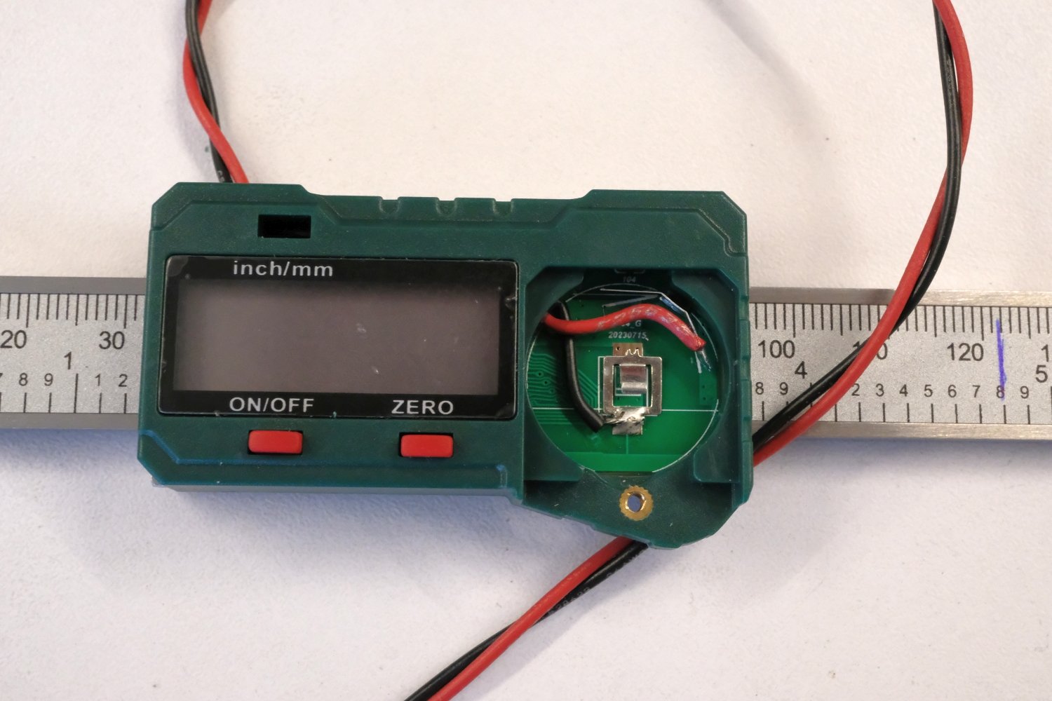
Hi Mike, I understand your wish to position the display at a more convenient location. The display is an LCD type and requires a large amount op signals to display the information. The power and signal connection to the pcb is done with a 'zebra strip'. That is a kind of foam with alternating layers that are isolators and layers that conduct current. It is compressed between PCB and display, so no connector is used. On some PCB's of digital calipers you can find 2 interface signals intended for connection to a remote interface. These are clock and data signals. In combination with a small microcontroller board (e.g. Arduino) you can then decipher the data and put meaningful values on an extra display. This type of caliper had no such interface. So I had to use the display as it is positioned over the ruler. You are right, the Y-axis hand wheel is very close to the readout but it is possible to use it. I should have cut the extruding bulb before mounting. That gives about 5mm extra play. Now that it is already glued in place, I leave it as is. I'm glad you like my report on this modification. best regards, Kris -
Mike Y reacted to a post in a topic:
Adding a cheap DRO to a Proxxon XY-table
-
CPDDET reacted to a post in a topic:
Adding a cheap DRO to a Proxxon XY-table
-
Adding a cheap DRO to a Proxxon XY-table
Kris Avonts replied to Kris Avonts's topic in Modeling tools and Workshop Equipment
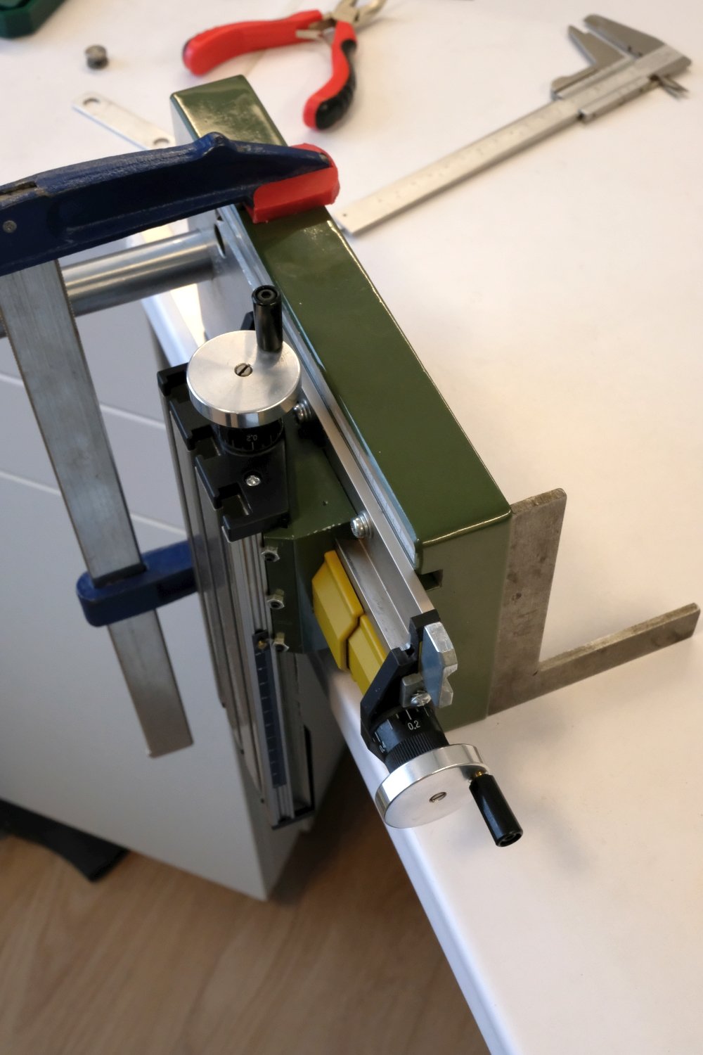
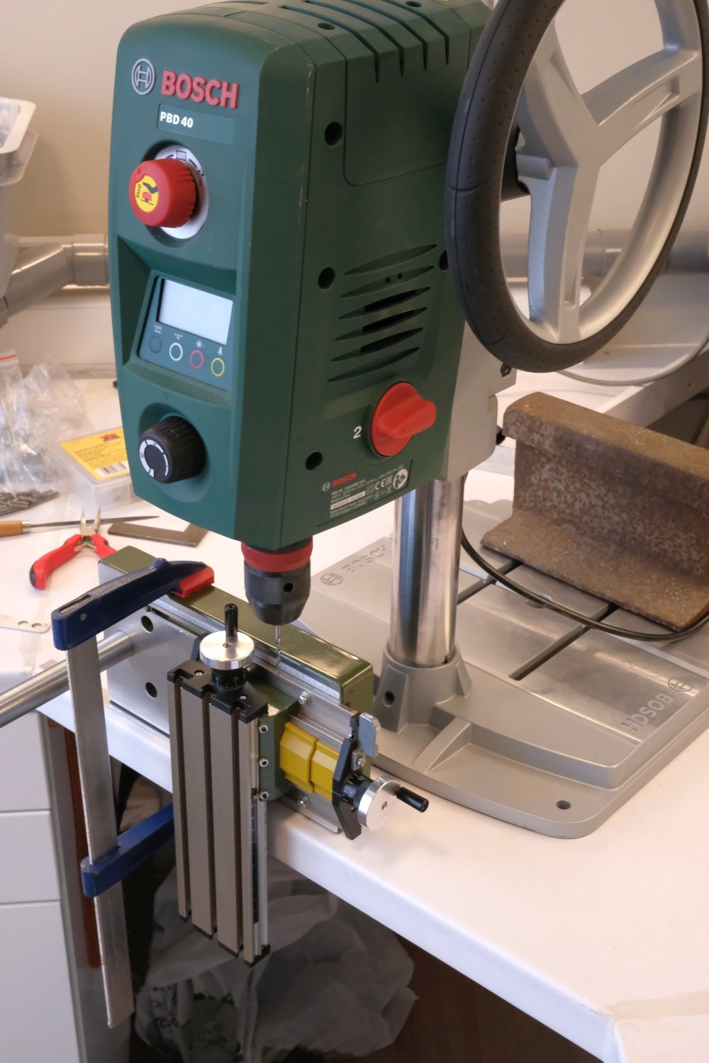
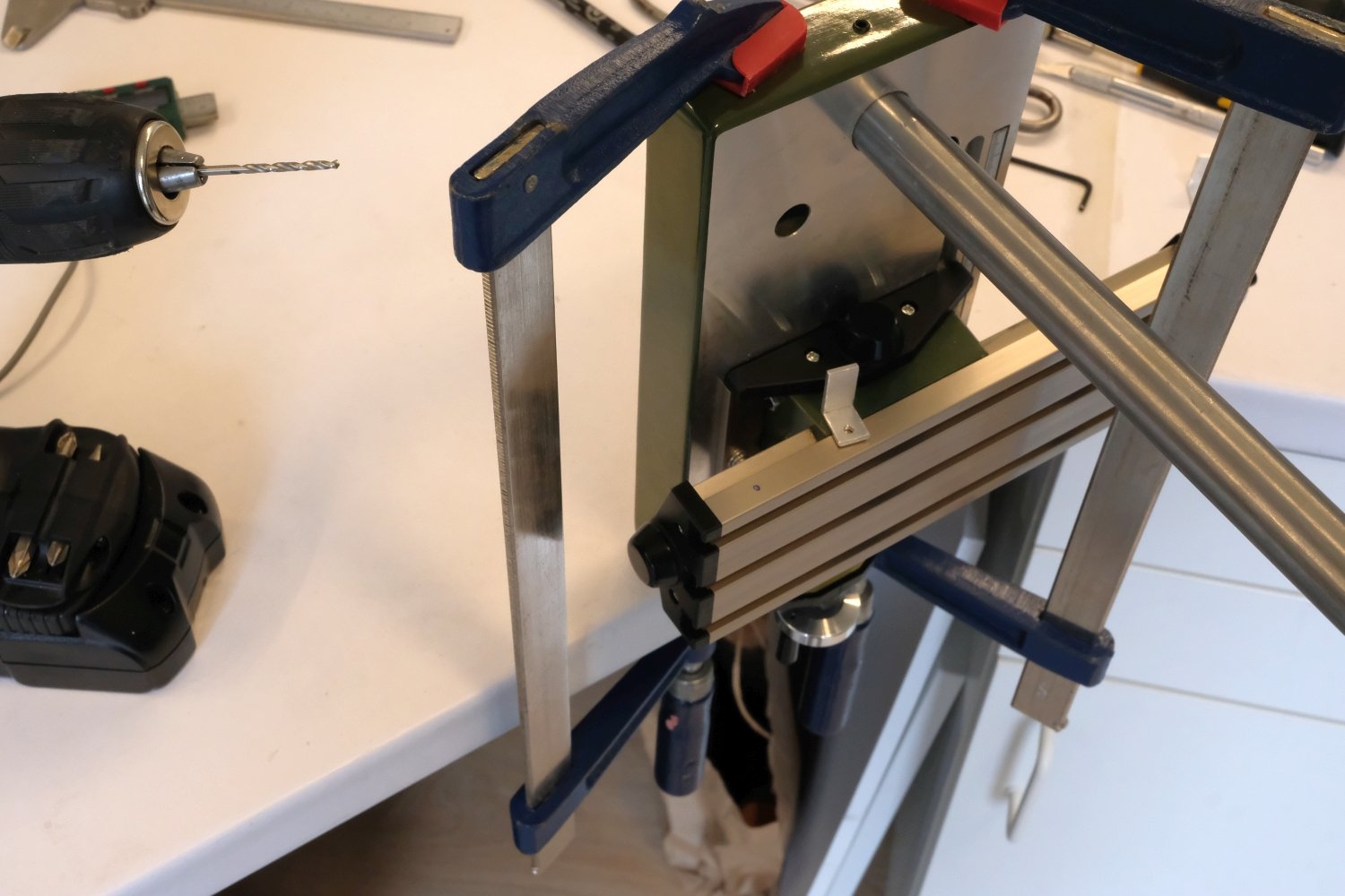
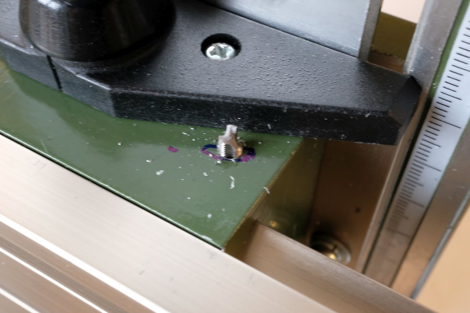
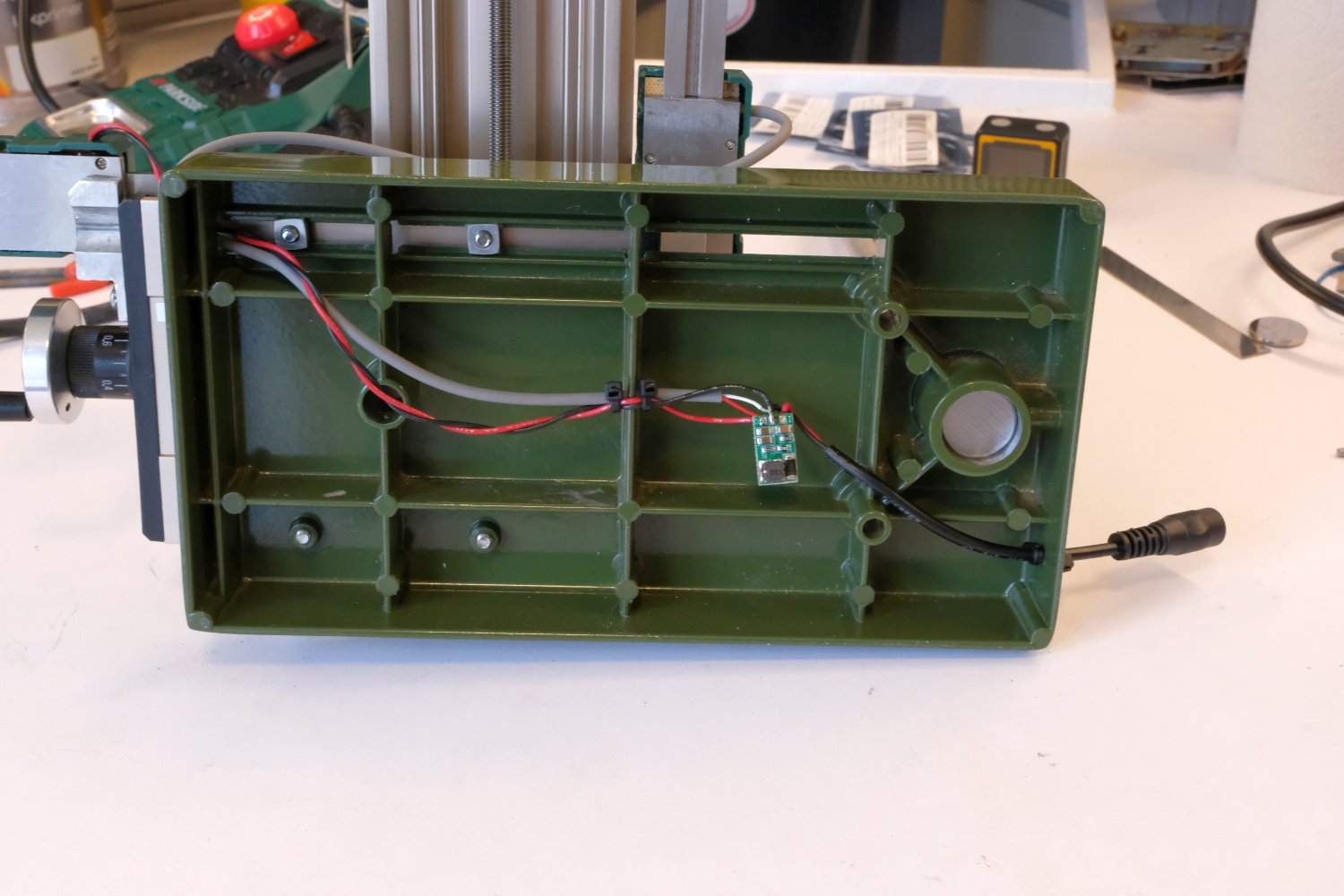
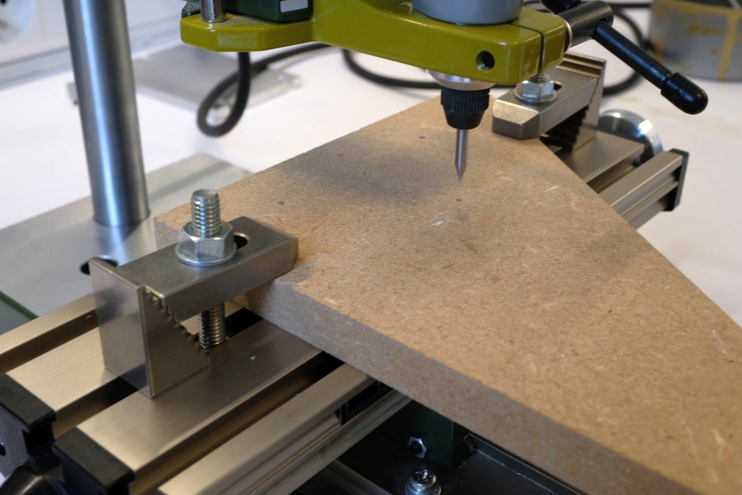
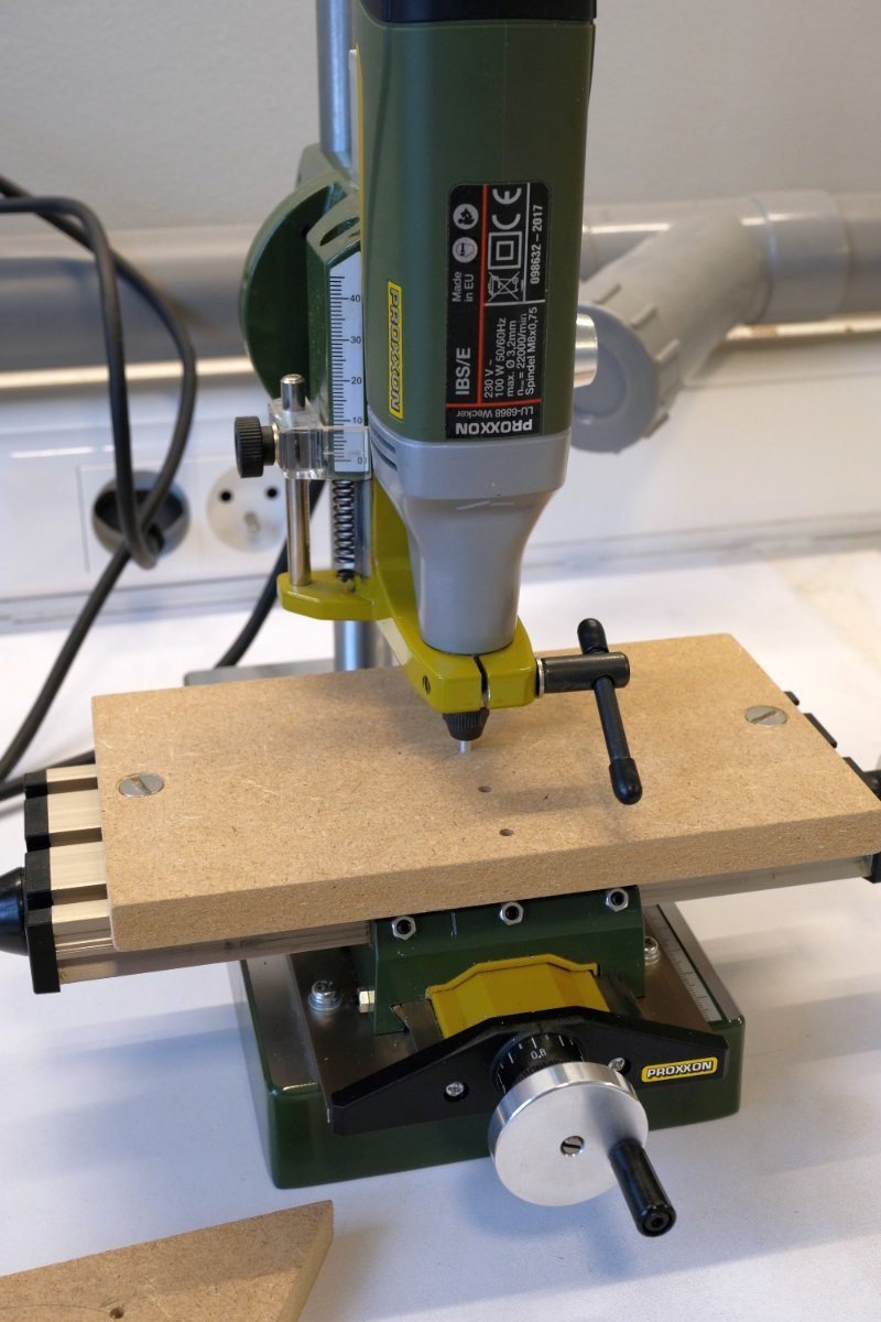
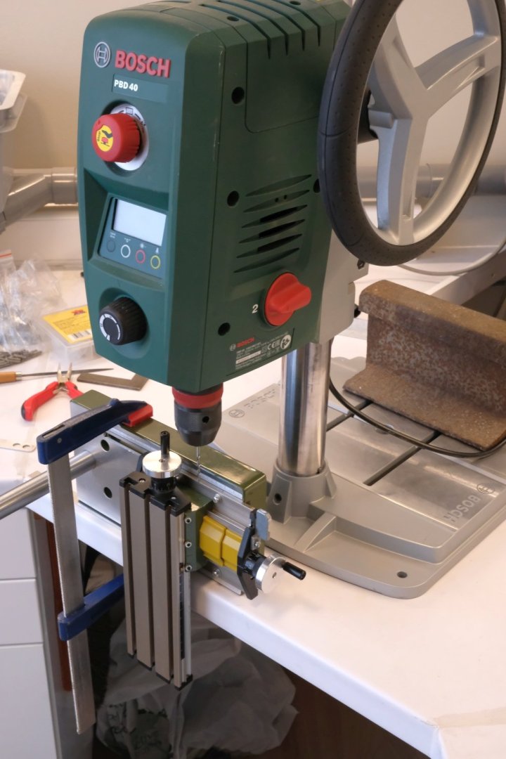
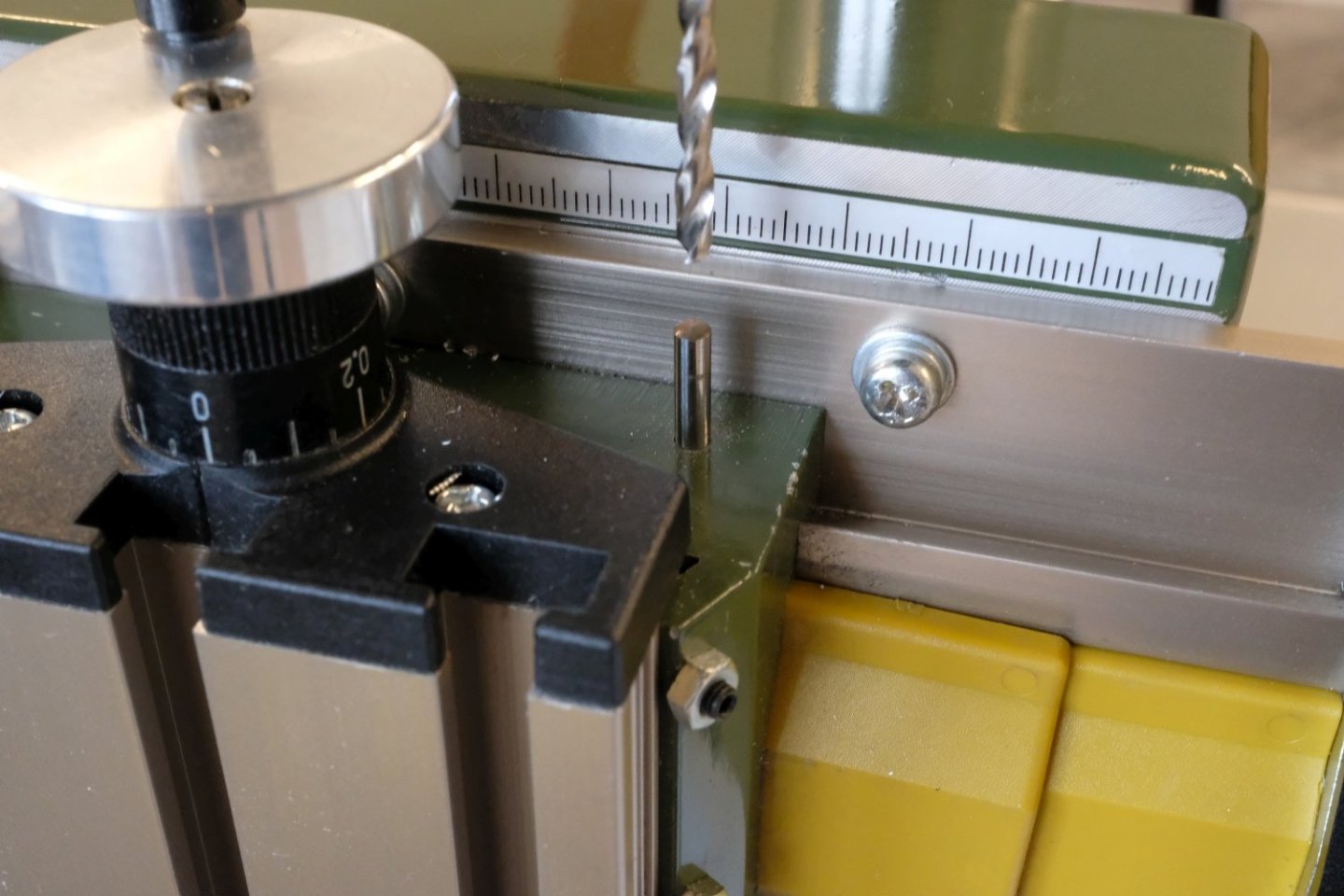
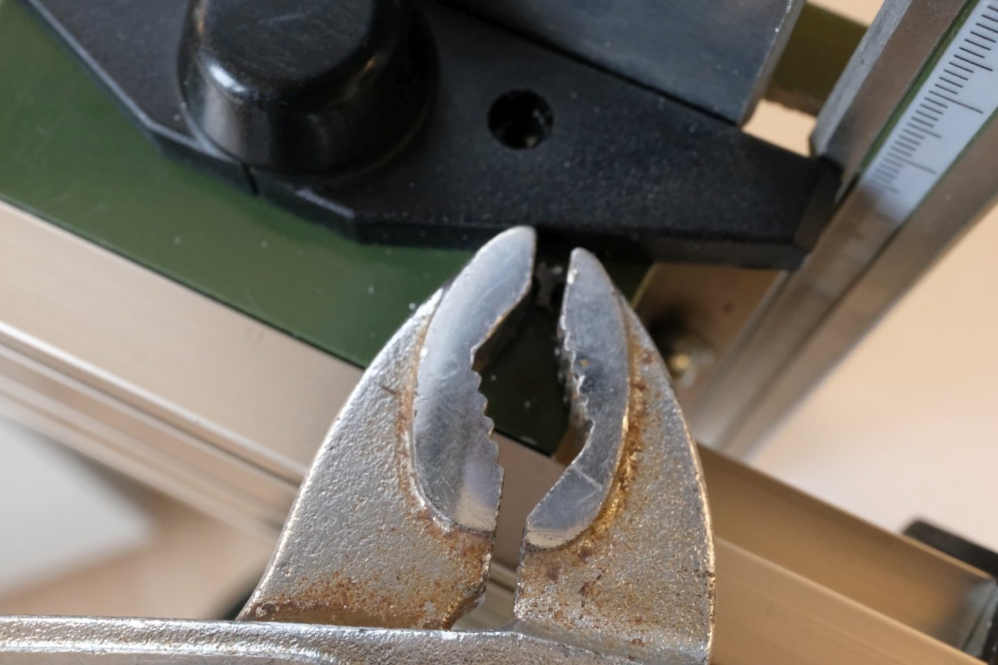
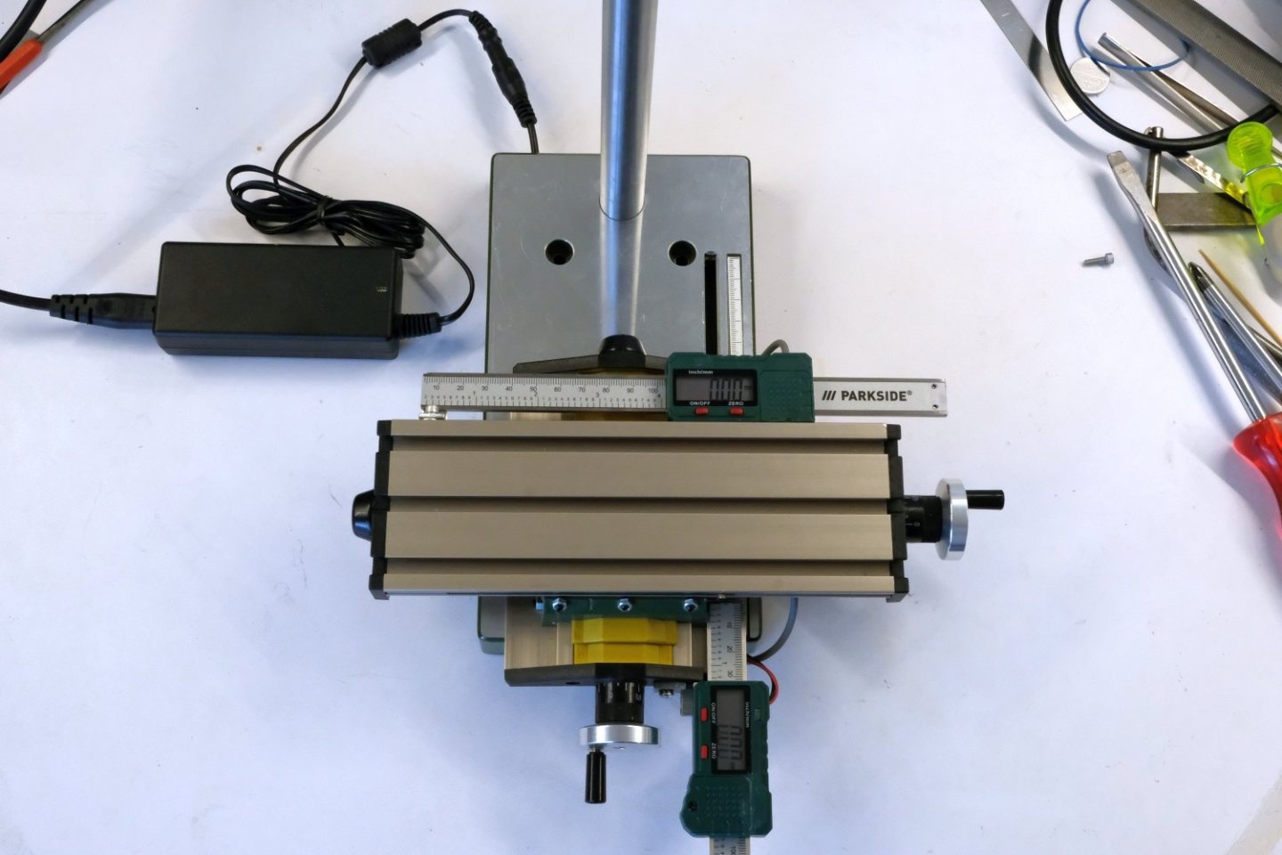
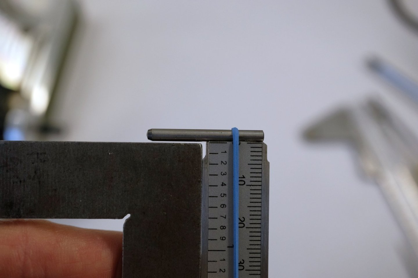
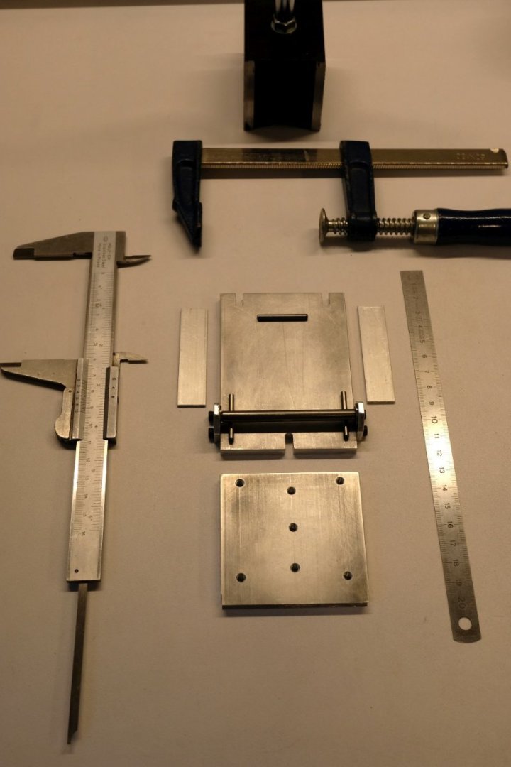
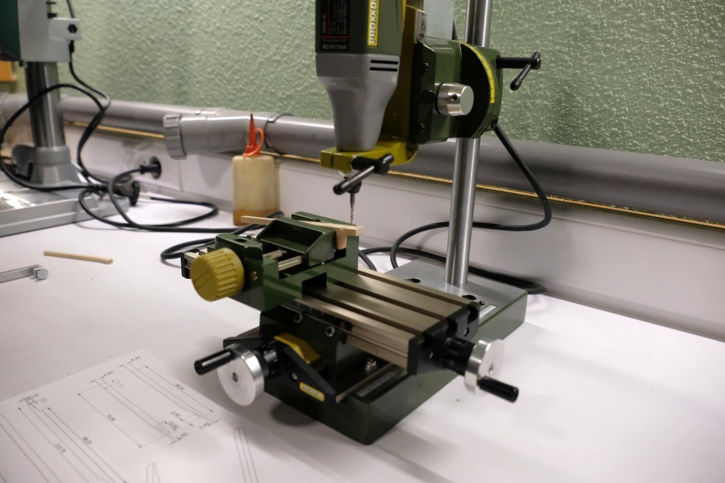
Hello, The next thing is to make a hole at the right of the cast aluminium block where the dowel pin will be inserted. I made a quite complex setup to drill that 3 mm hole as correct as possible. First job was the fixation of the xy-table to my work surface and checking its squareness (see the next picture). Then a rather unusual setup for my drill press where the base was turned to the back and using a counterweight to stabilize the drill press. That went well and the dowel pin fits with very little play. As a last adaption for the Y-readout, I soldered some wires to the metal battery clips in order to power the readout from a power supply. That should avoid battery replacements in the future. The X-DRO was made following the same principles but the ruler will be fixed to the mill table with a support instead of a pin. The next picture shows the readout already prepared with wiring, the ruler and both supports. You may notice that I cut away some plastic at the battery location to bring the readout as close as possible to the X-table side. Then the supports need to be fixed. The ruler support is attached to the mill table. With the threaded hole for the readout support I had bad luck. The M3 tap broke off but there was just enough of it sticking out so that I could remove it with a good forceps. The next picture shows the parts of the X-DRO ready for glueing to the mounted supports. Then with some metal epoxy glue all parts are glued, compressed and left for 24 hours to allow the epoxy to cure to its final strength. As a last addition I soldered the wiring to a small step down converter that will supply the 3V DC for both readouts. At the back is now a connector that mates with an old 12V DC supply of a laptop. Here is the finished KT 70 with its added DRO. Next time I will try to report on some test regarding the precision of this setup. Best regards, Kris


-
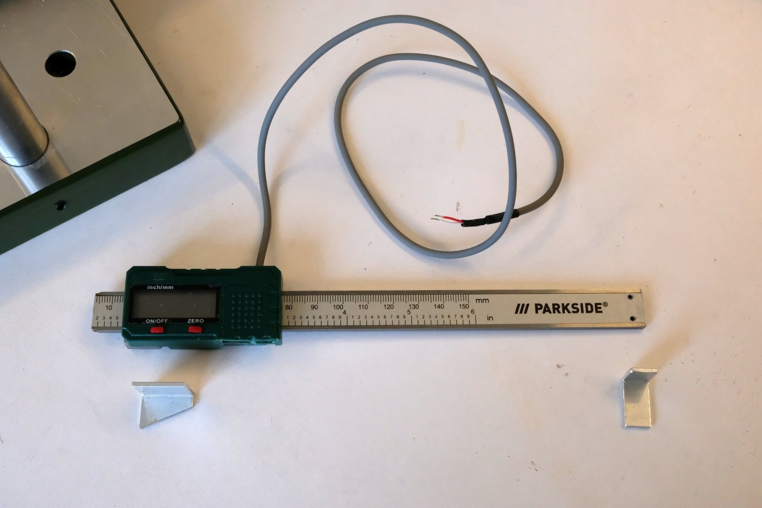
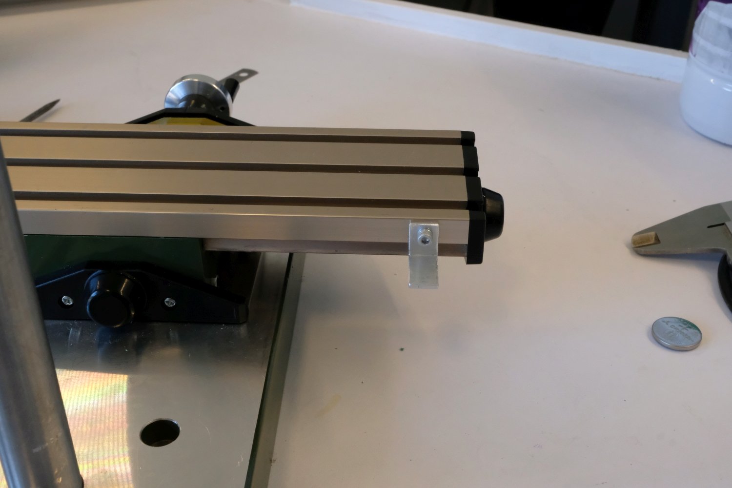
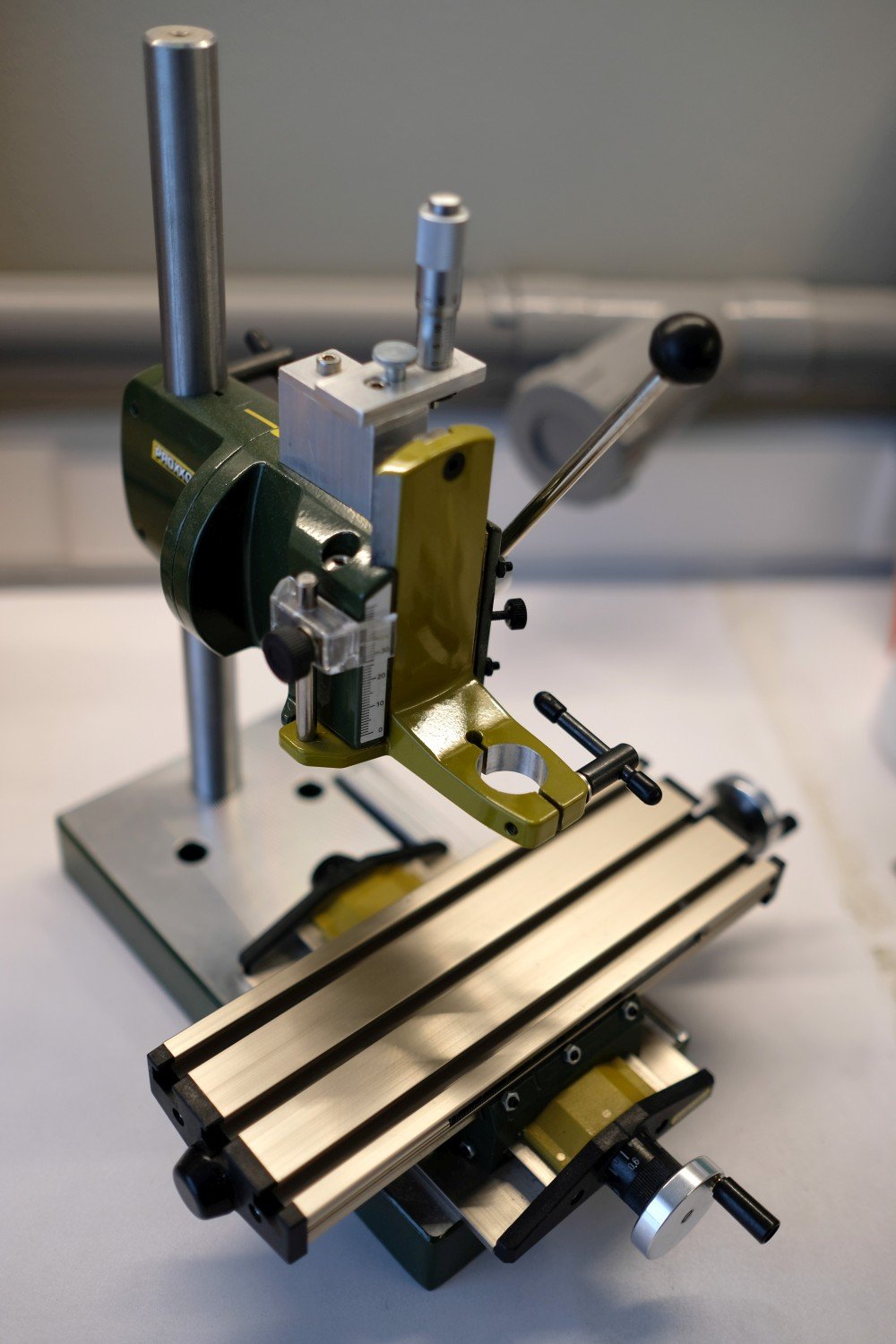
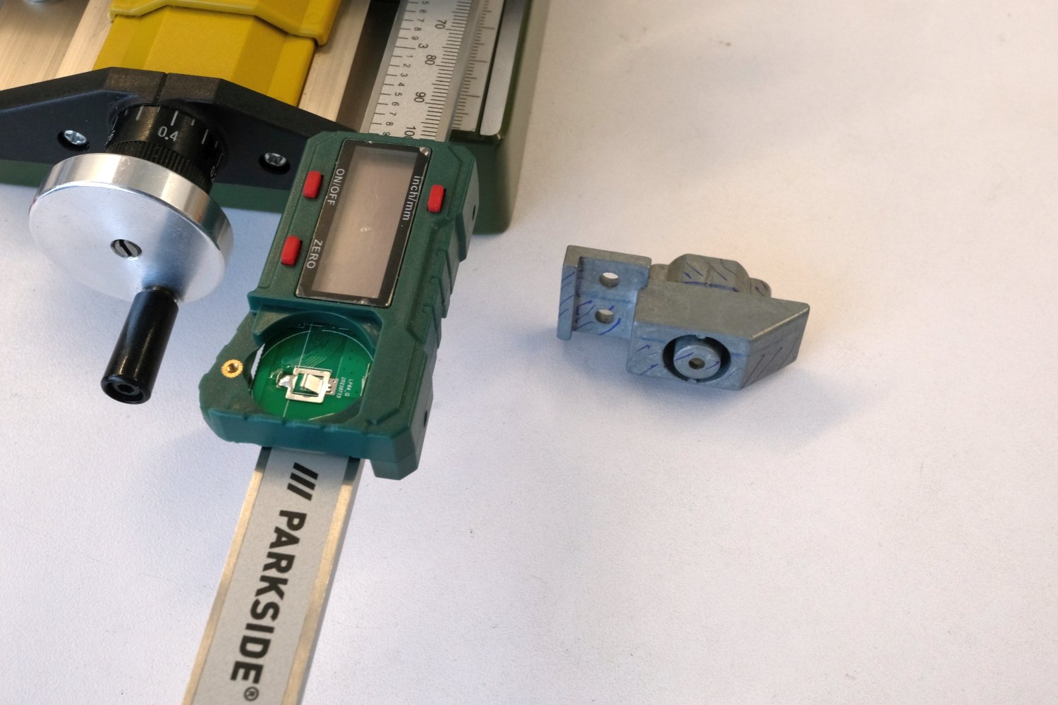
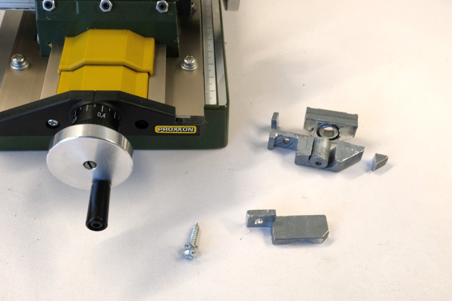
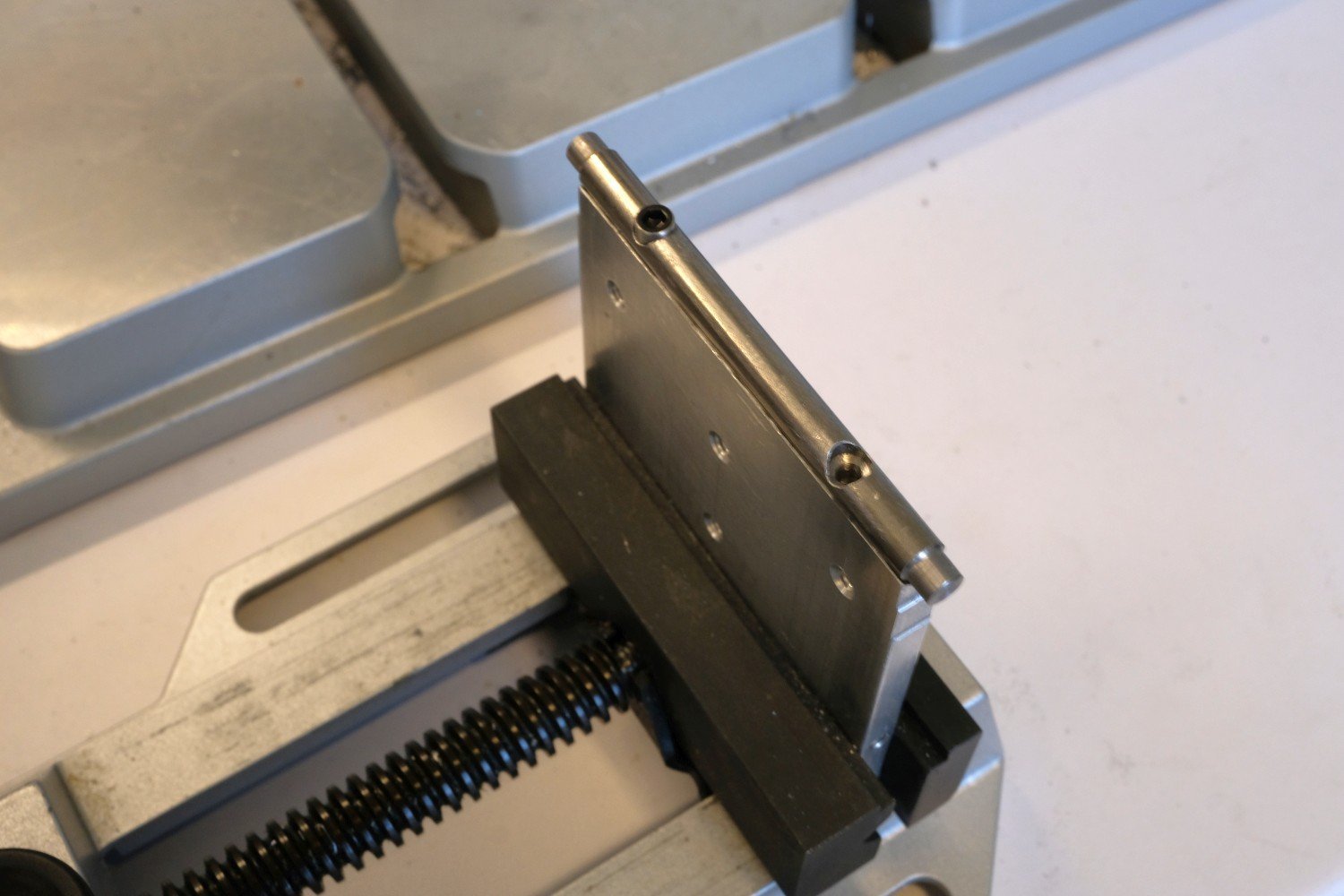
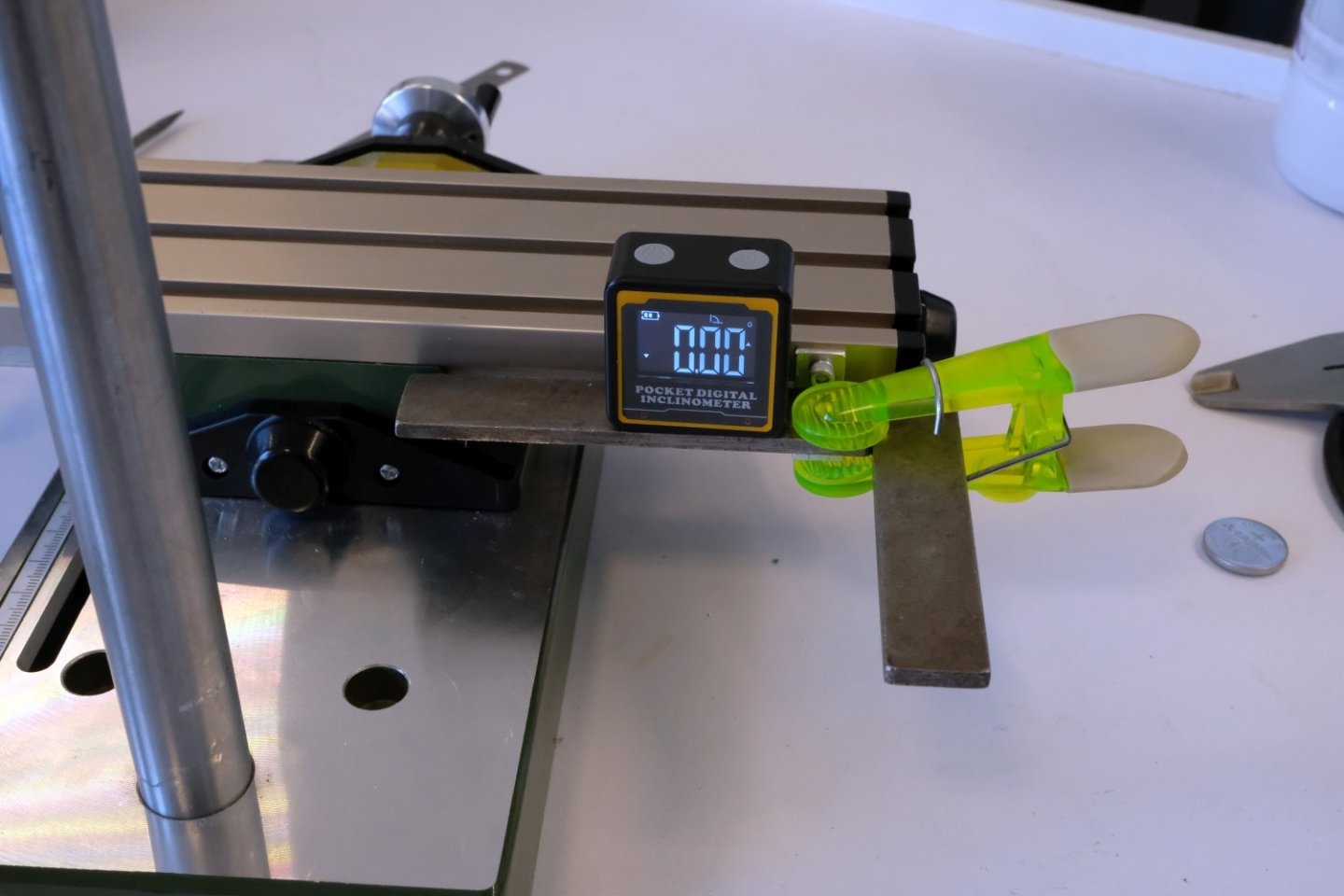
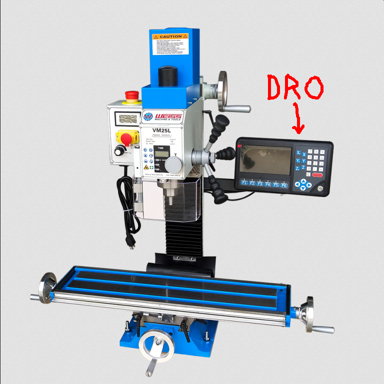
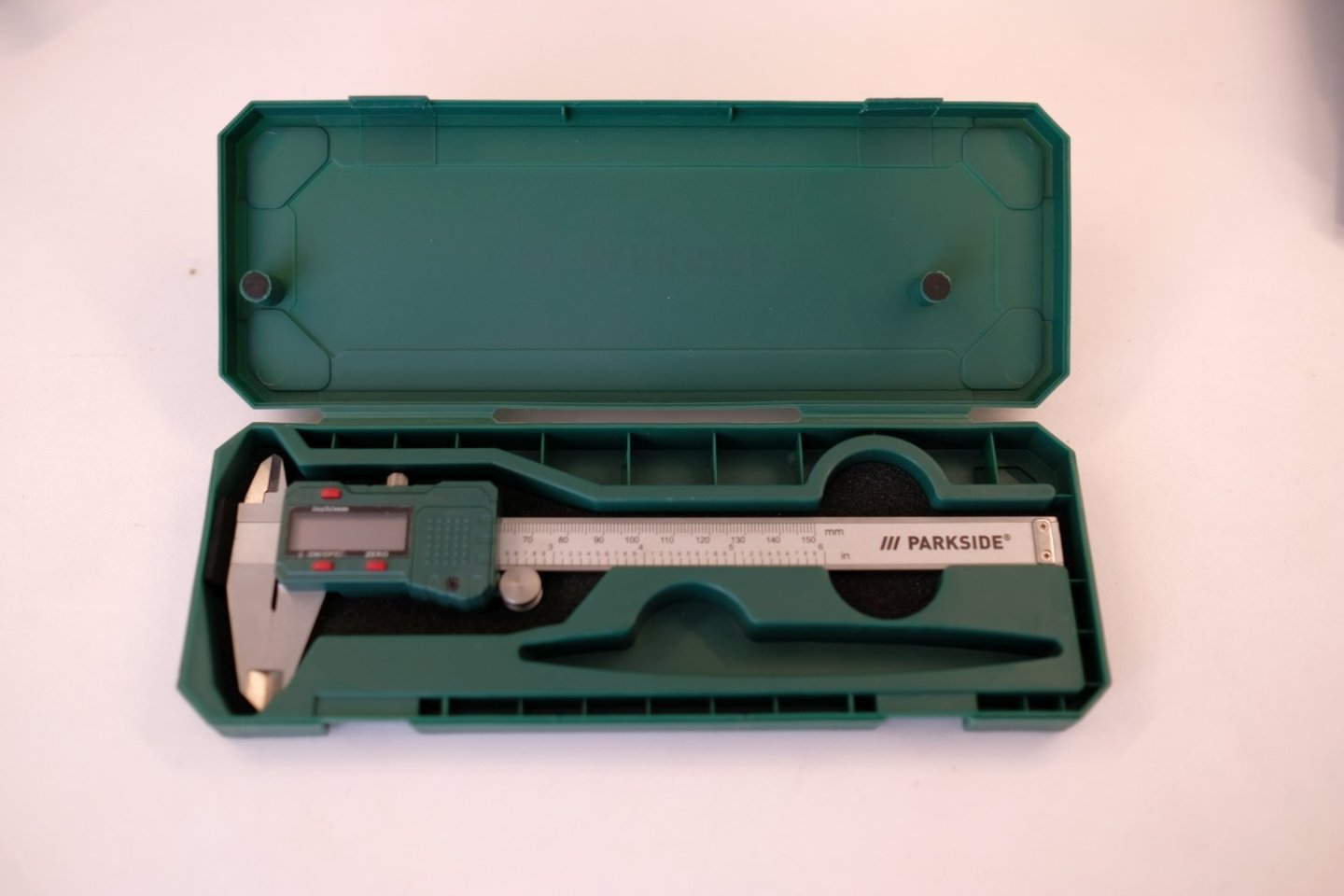
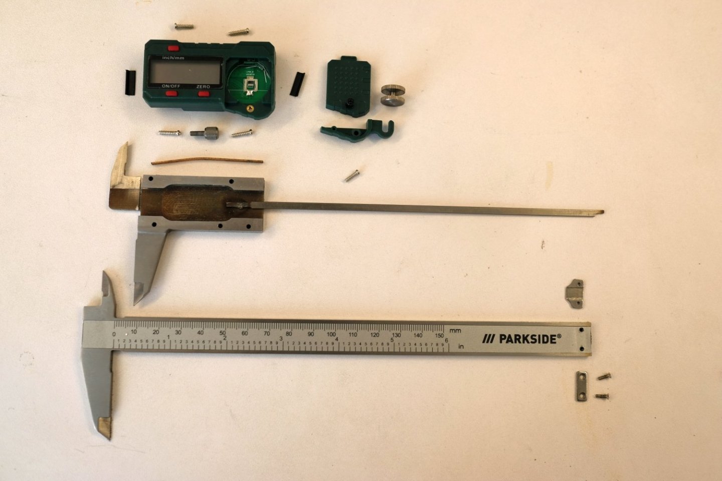
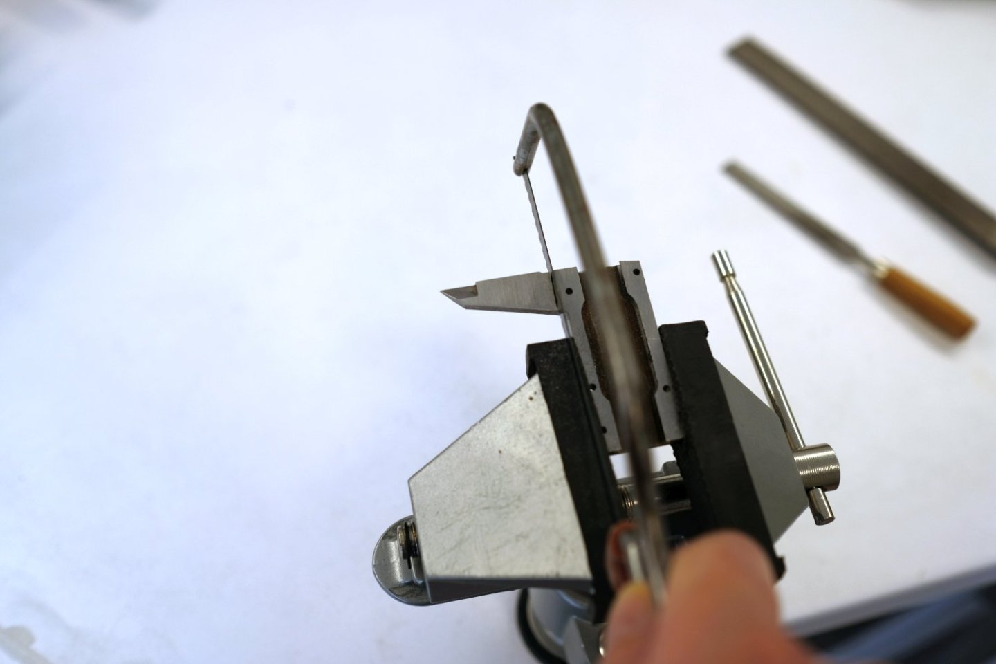
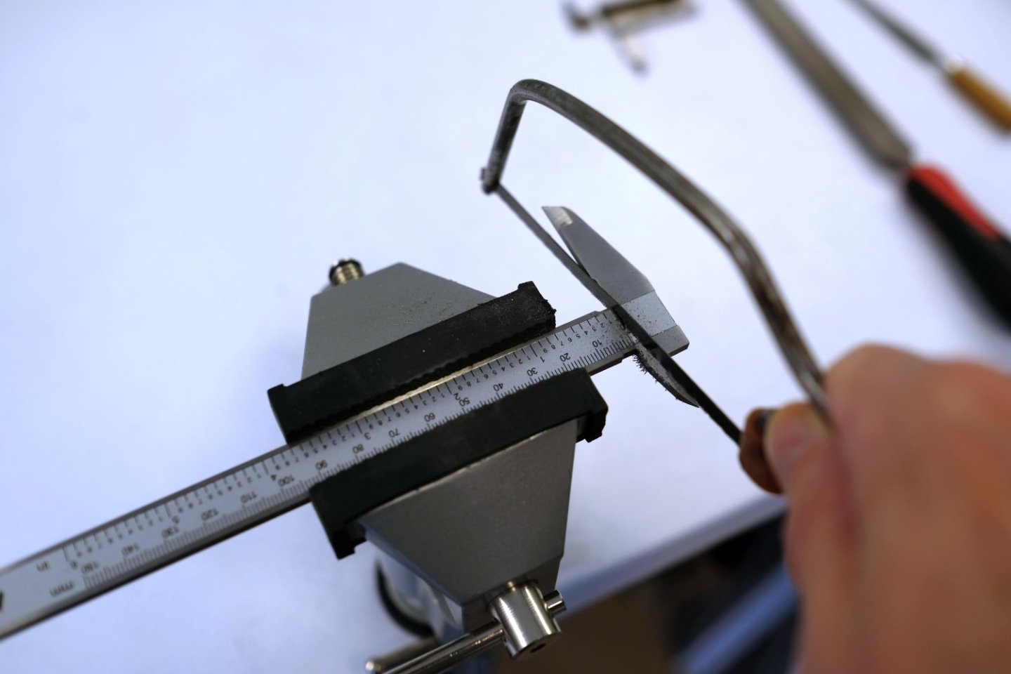
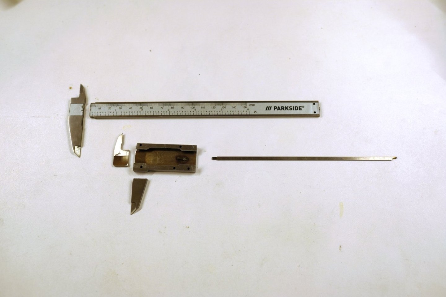
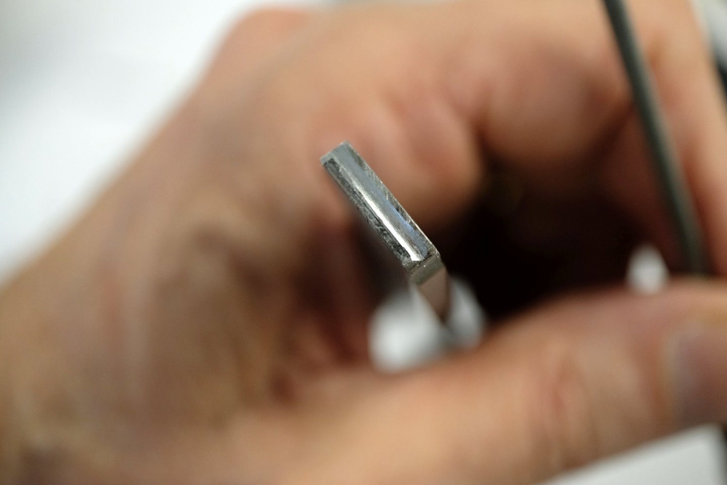
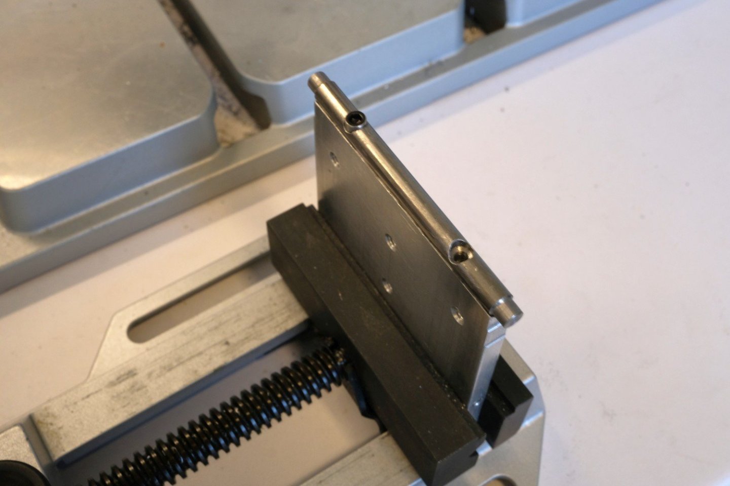
Hello All, I use my Proxxon micro-mill a lot when it comes to precise shaping of wooden parts. The complete setup consists of a MB 200 drill stand, a MICRO compound table KT 70 and a 230V ISB/E drill/grinder. One of my frustrations with this setup is keeping track of the position of the end mill relative to the workpiece. How many turns did I already gave in the X or Y direction? Of course each decent mill is equipped with a Digital ReadOut system (DRO). But adding such hardware to the KT 70 is not obvious, especially because the KT 70 is a ‘MICRO’ xy-table. I also didn’t want to spend a lot of money on it, so I parked it in a wish list. But then I saw that digital calipers were sold at 7.99 euro in a supermarket. I couldn't resist and bought 2 calipers guided by ‘it’s now or never’. So I will describe here the process of adding these calipers to the KT 70. It is certainly not the only way to do it but it is what worked for me. And maybe it can inspire other members. So lets start. The first thing is to dismount the complete caliper. Then the metal parts need some cuts. I used a small hacksaw but soon experienced that the metal was quite hard and I had to replace the saw-blade twice before finishing the job. I was afraid that these cuts would disturb the measurement principle. I quick check gave me piece of mind. Then you have to decide where you want to attach the ruler part of the caliper and where the readout unit. After some puzzling, I decided to position the readout units close to the respective hand-wheels. The ruler then needs to be attached to a moving part of the xy-table. For the Y-direction I will use a 3 mm dowel pin glued in a filed grove at the ruler end. To mount that Y-ruler as low as possible, a small cut had to be made at the right front corner of the xy-table. This way the Y-ruler can be positioned horizontal as the check on the next picture illustrates. Next the Y-readout needs a support. I found a complex metal (zamac) part that could be used when all excess material was cut away. It will be fixed in place using the right screw (original screw replaced by a longer one) in the lower cover. That is enough work for today, have a nice evening and see you back soon. Best regards, Kris


-
Kris Avonts reacted to a post in a topic:
The Hayling Hoy by jpalmer1970 - 1:48 scale - First POF build
-
Kris Avonts reacted to a post in a topic:
A small tilting table for a mini proxxon mill.
-
Hi Wefalck, You are right, it was a serious challenge but I'm glad I could make it to a usable tool. In a 3D cad program it all seems very simple (no tolerance and no misalignment) but in the real world it requires some skills to get it done. Your solution is indeed simpler and very robust. For me it comes a little too late. I hope my tilting table will serve me well for upcoming ship projects. best regards, Kris
-
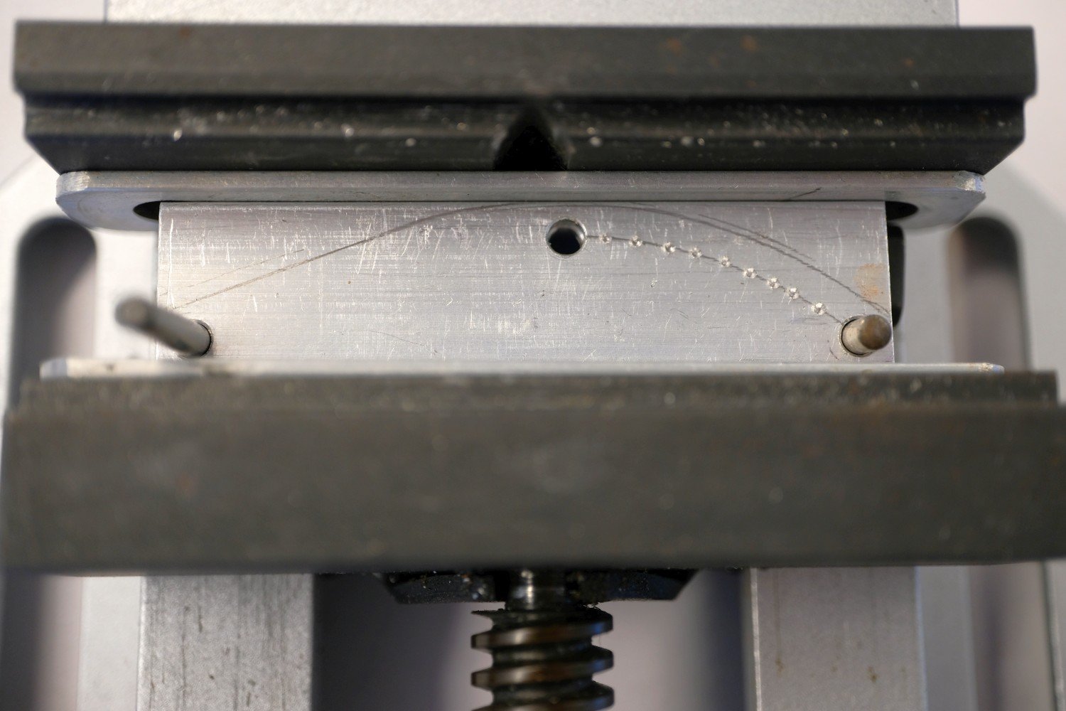
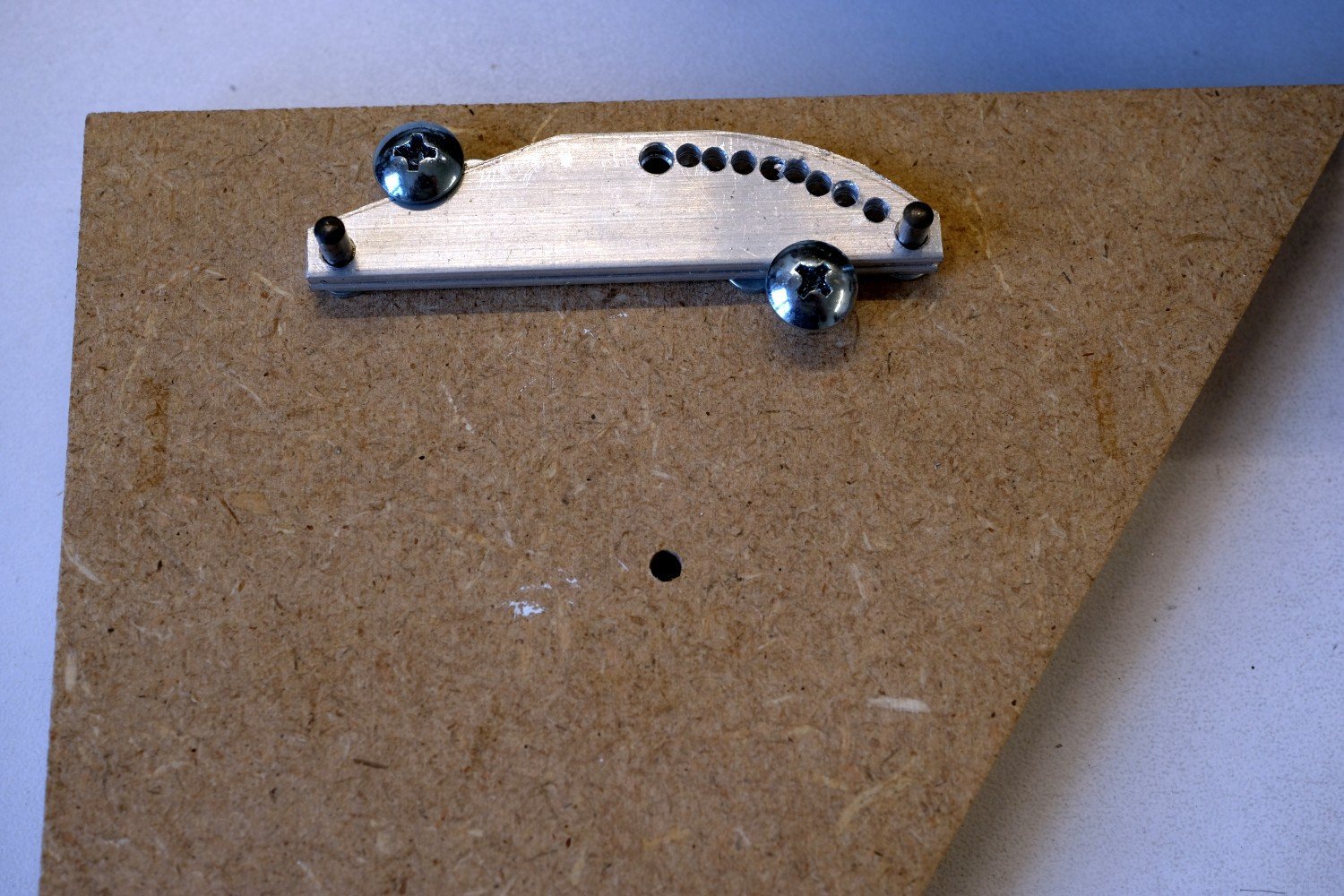
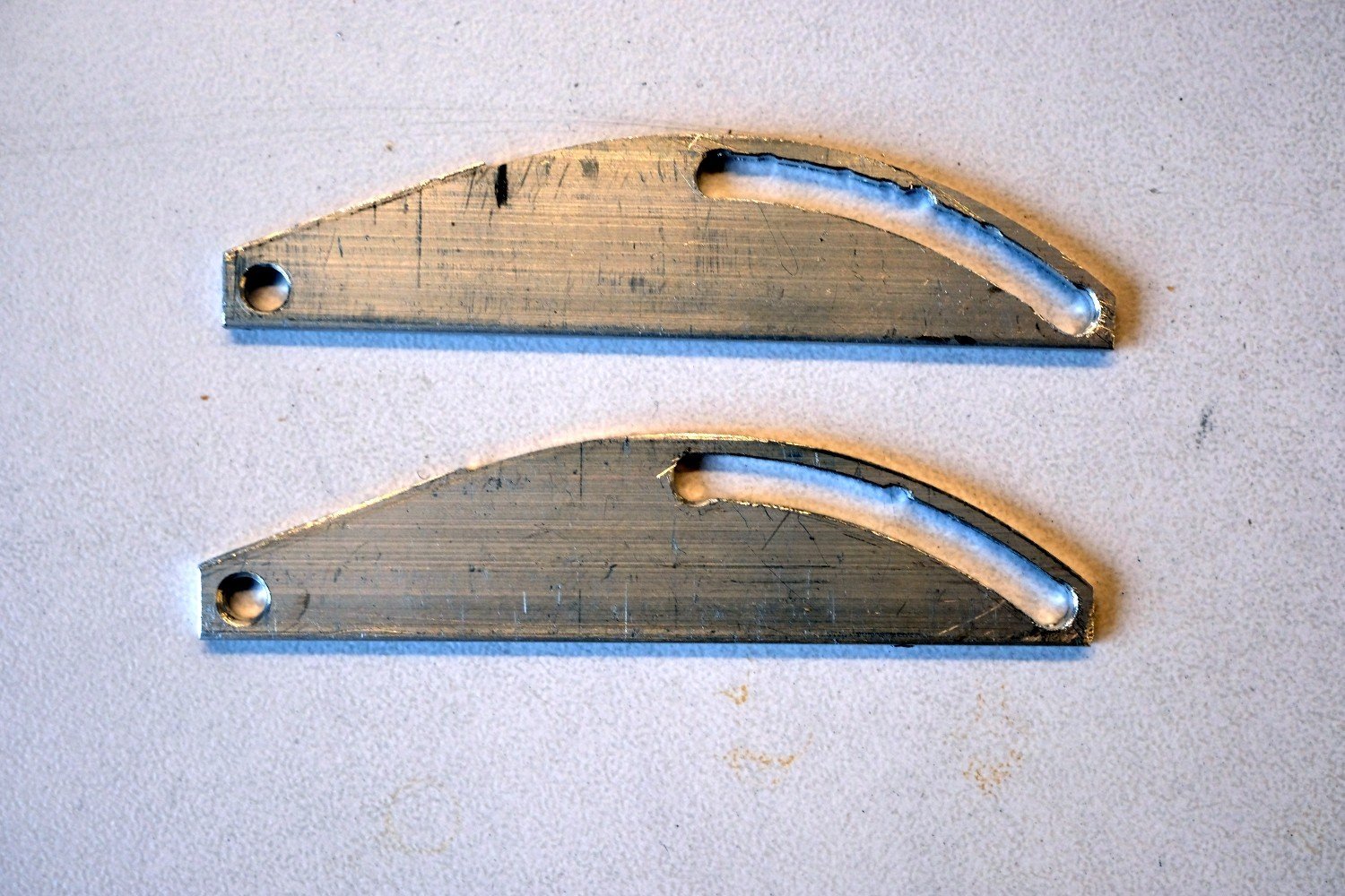
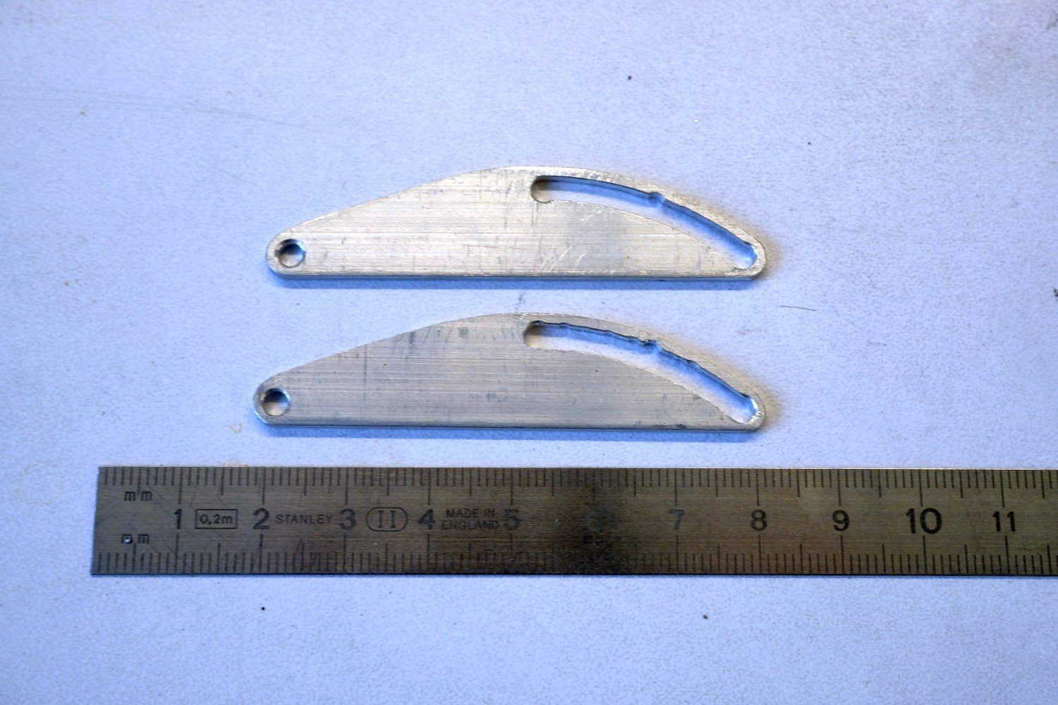
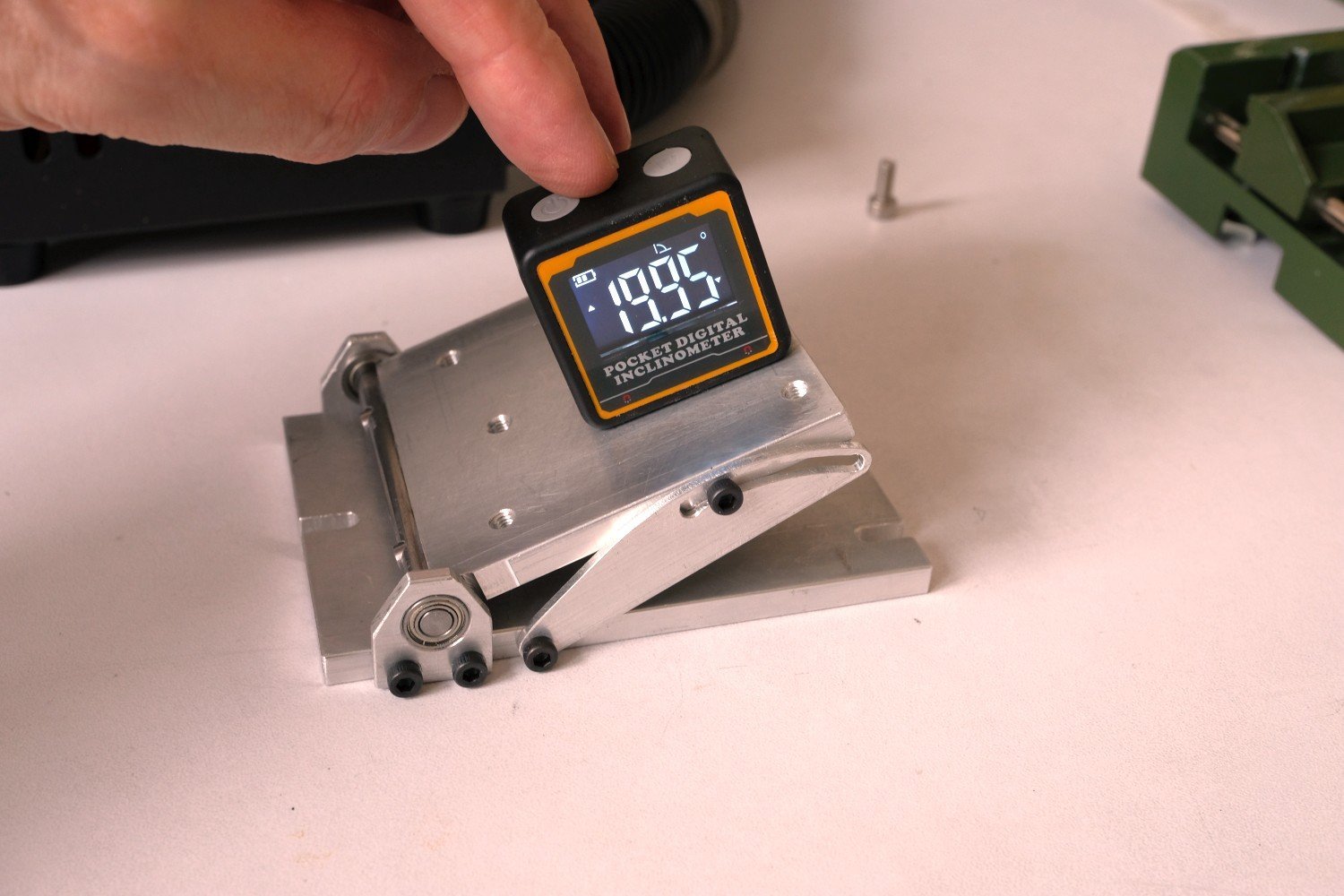
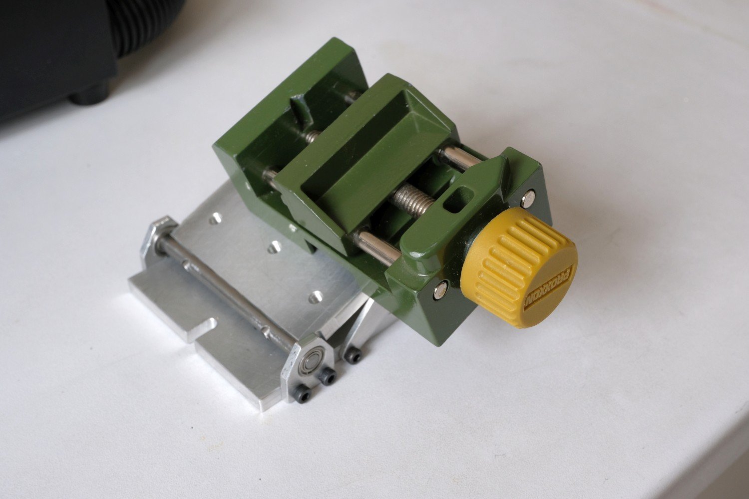
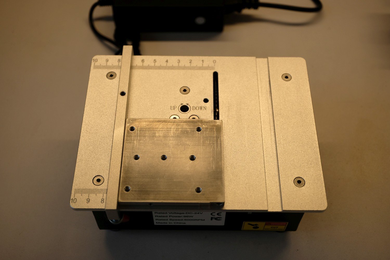
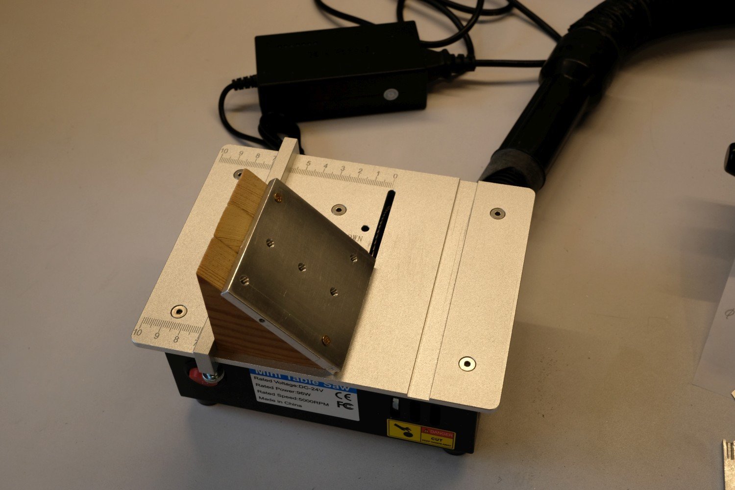
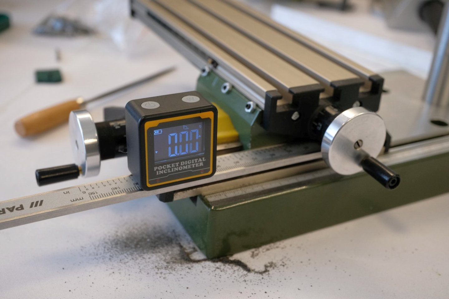
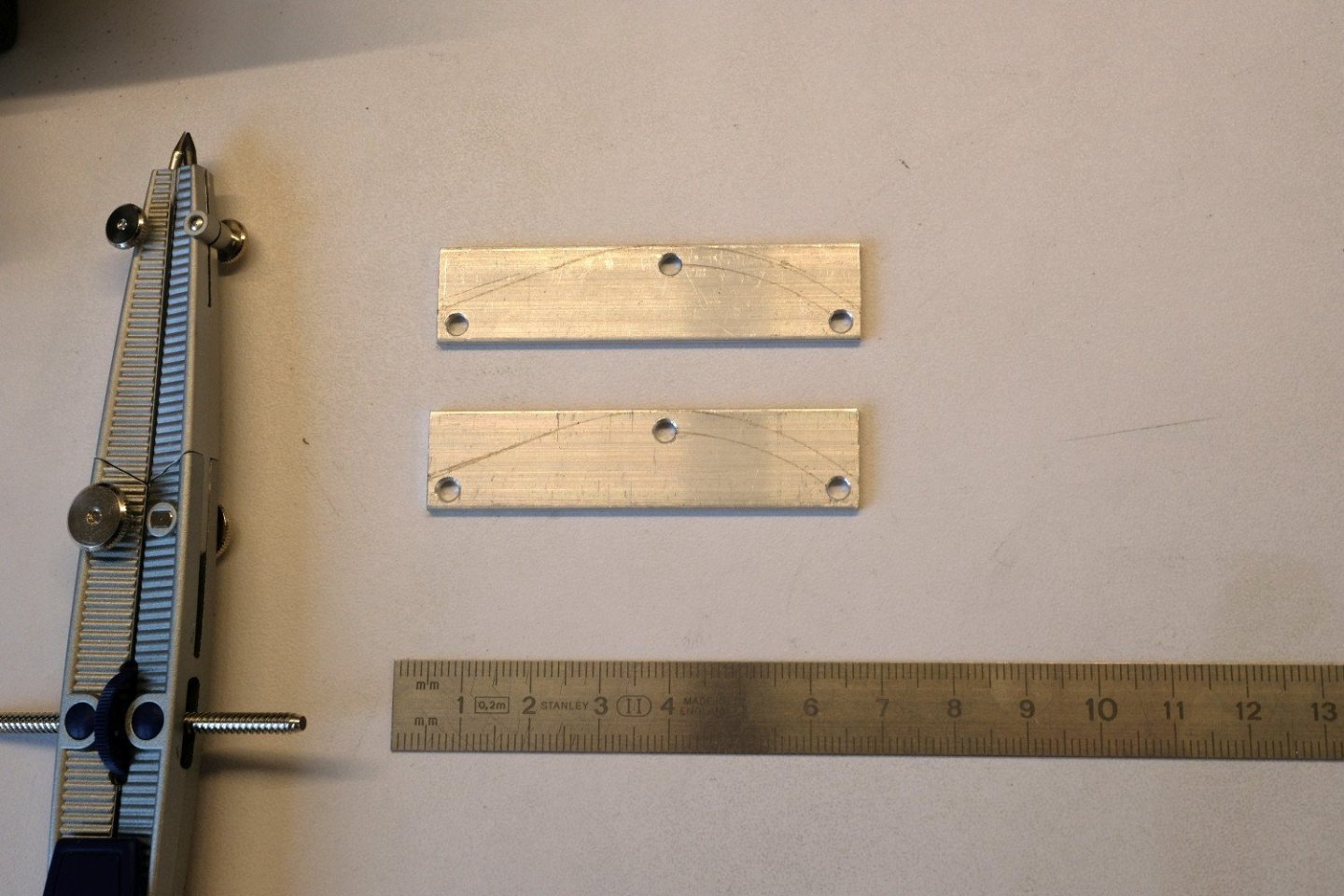
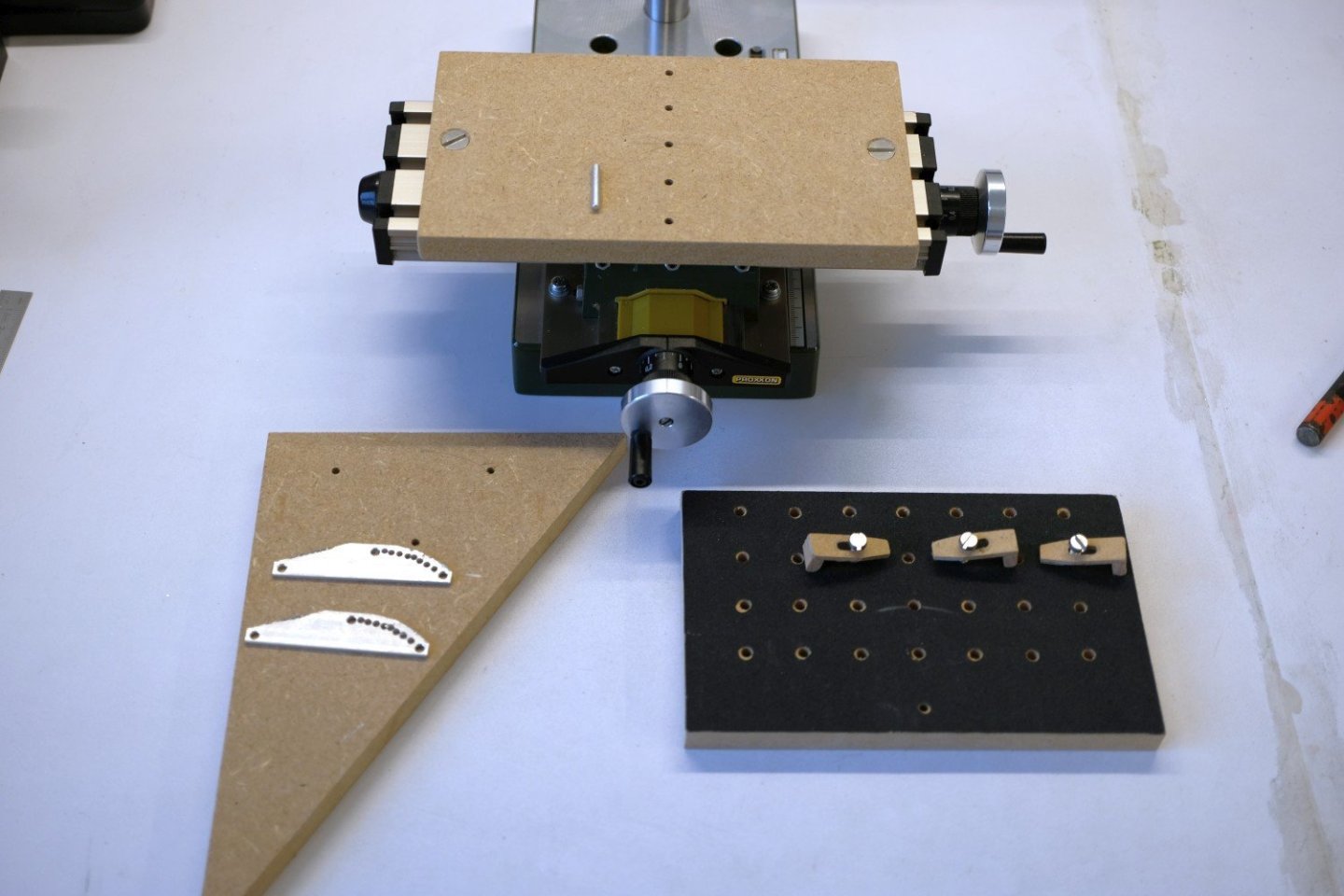
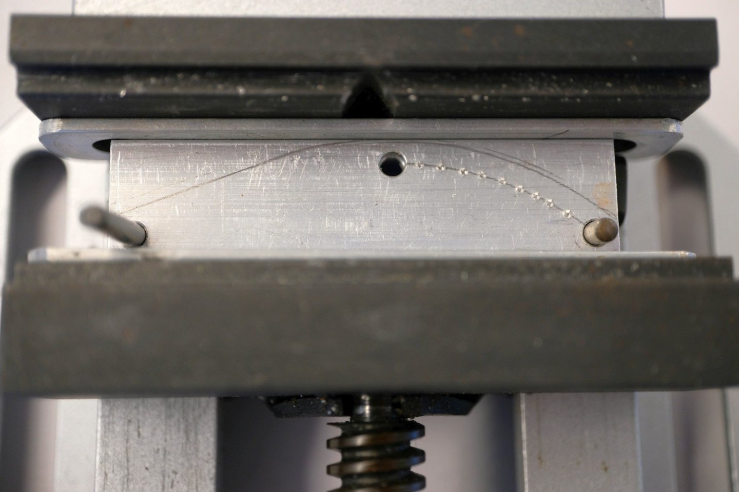
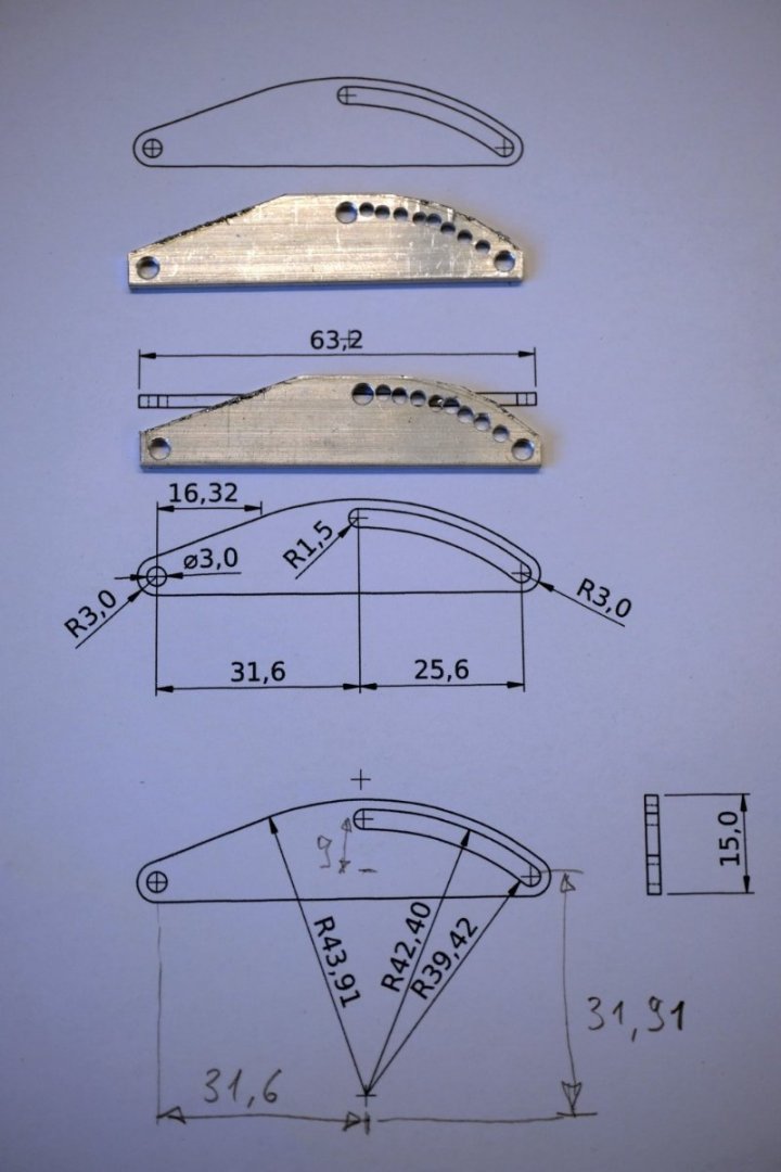
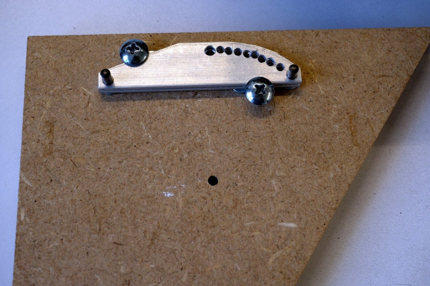
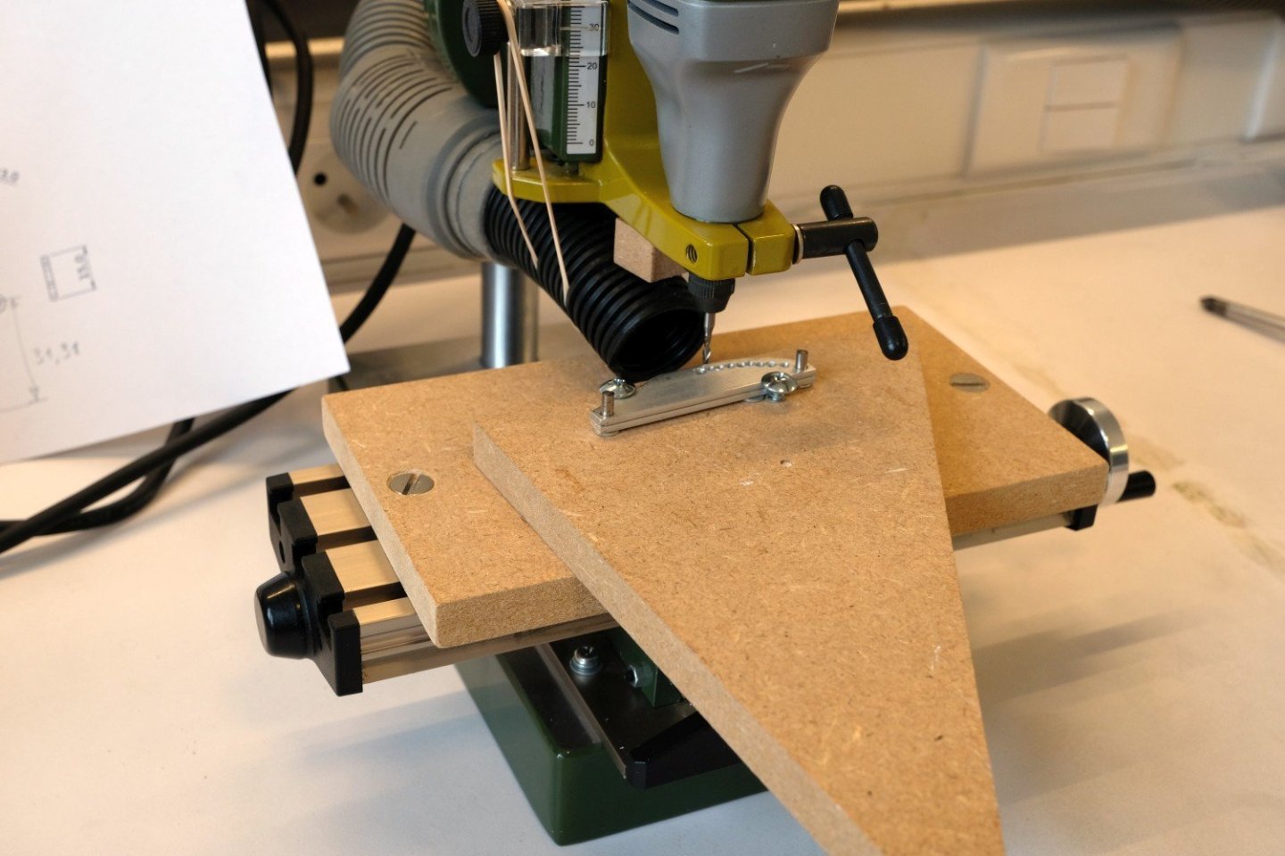
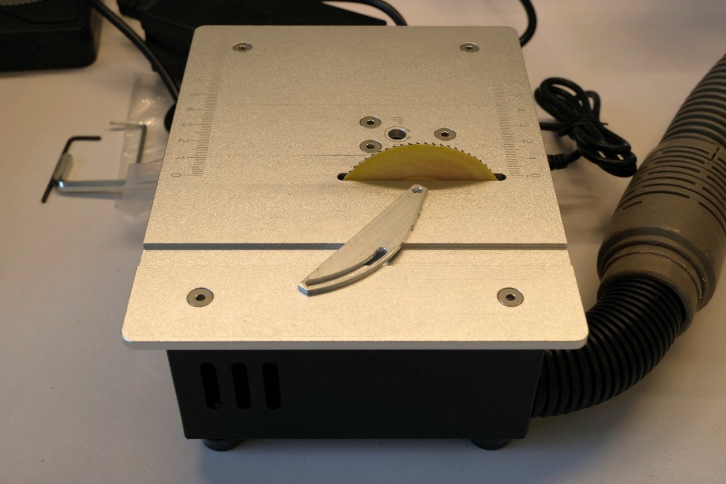
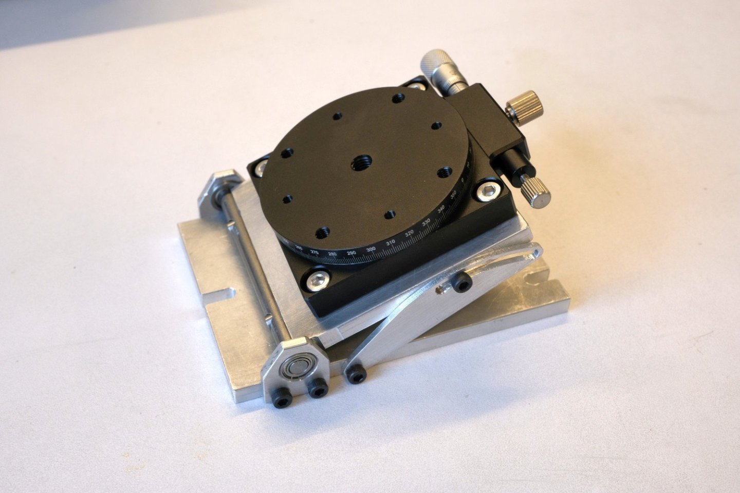
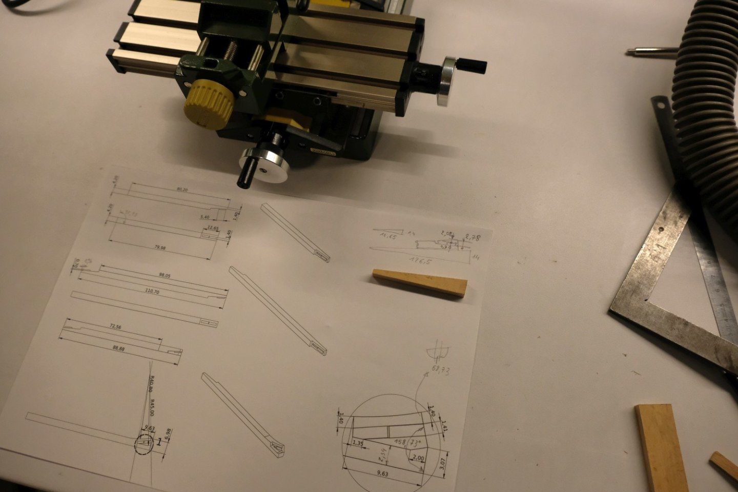
Hi All, After the metal epoxy glue had set (24 hours), 2 bolts are added just to be sure it will withstand vibration and forces during milling operations. Curious about the outcome of the glueing I measured the misalignment. As you can see in de following picture there is a small gap (0.1 mm) between the highest point of the cylinder and the tilting plate. Next was again a check of the flat surface on the xy-table over a 50x50 mm area. I was disappointed but the inclinometer showed it as ‘flat’, so I will accept the result and start making the last parts: the 2 plates that lock the tilted plate in position. The tilt-locker plates have an arc at its top and a slit also in the form of an arc. All arcs have the same centre point. First I start with marking and drilling 3 holes as a reference. To mill the arcs I will use a jig that I already made earlier and consists of a base plate with 5 positions, spaced 20 mm apart, that can hold a pin that will act as the rotation centre. The next picture shows it on the xy-table. For wooden parts I use a plate with some sandpaper glued on it and lots of holes that have an M4 nut at the back of the plate. A workpiece can then be fixed with some small clamps. For the metal tilt-locker parts I need firmer clamping, so I will construct a different plate from a scrap piece of MDF (shown bottom left in next picture). It starts with marking 3 positions: 2 holes of the tilt-locker and the centre of the arcs. For the arc slit, a number of holes along the arc are marked and drilled. Next I use my mini saw to cut off some excess material of the plates. Then both plates are fixed on the piece of scrap MDF. Milling starts with positioning the base MDF plate: the centre pin is mounted in the proxxon mill and lowered to make a fit in the middle hole of the base plate. Then the base plate is fixed in place to the xy-table with the 2 sunken bolds at its sides. The proxxon mill is brought up again and the centre pin replaced with a 2 mm end mill. The center pin is now placed in the lowest hole. That makes the distance from rotation centre to end mill centre exactly 40 mm. From there the y position can be set at the required position to start milling, see next picture. The result of milling: For the final shaping of the tilt-locker plates I convert my mini saw into a mini disc sander. The finished parts are shown next (you can see that at least 1 hole was drilled a bit to much off centre). And here is the tilting table, set at a 20° inclination. It can hold the MS4 machine vice as well as a small rotating table (if I ever need that extra degree of freedom for a workpiece). As a last tip to set an inclination with good precision, you can use a long M4 bolt to make fine adjustments before tightening all 4 M3 bolts. That ends the making of a small tilting table. Hope you enjoyed it and maybe you start making your own. Best regards, Kris


-
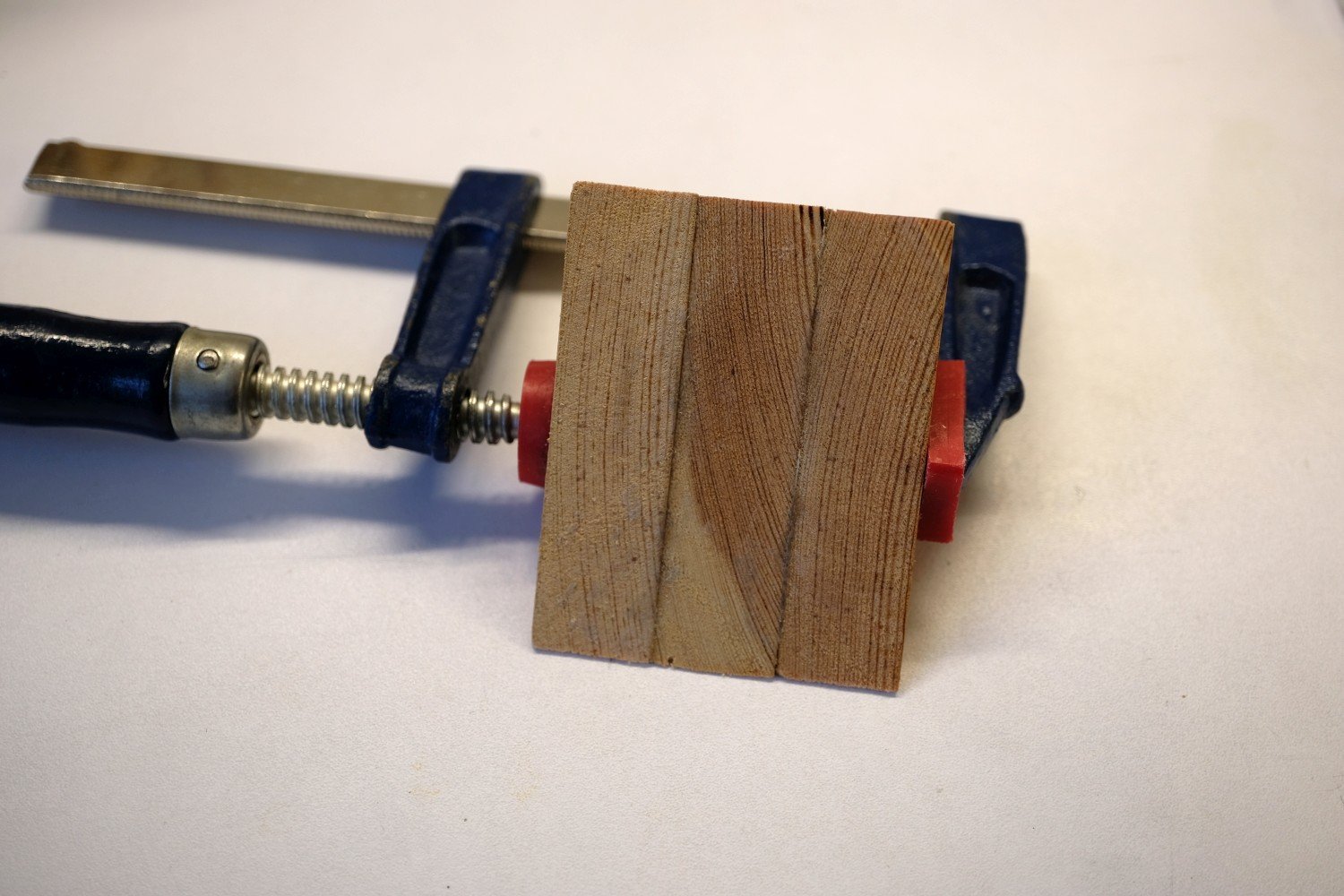
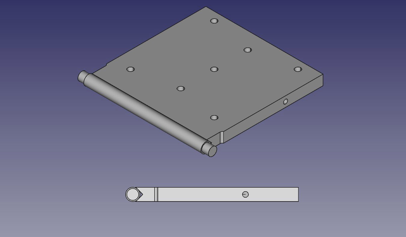
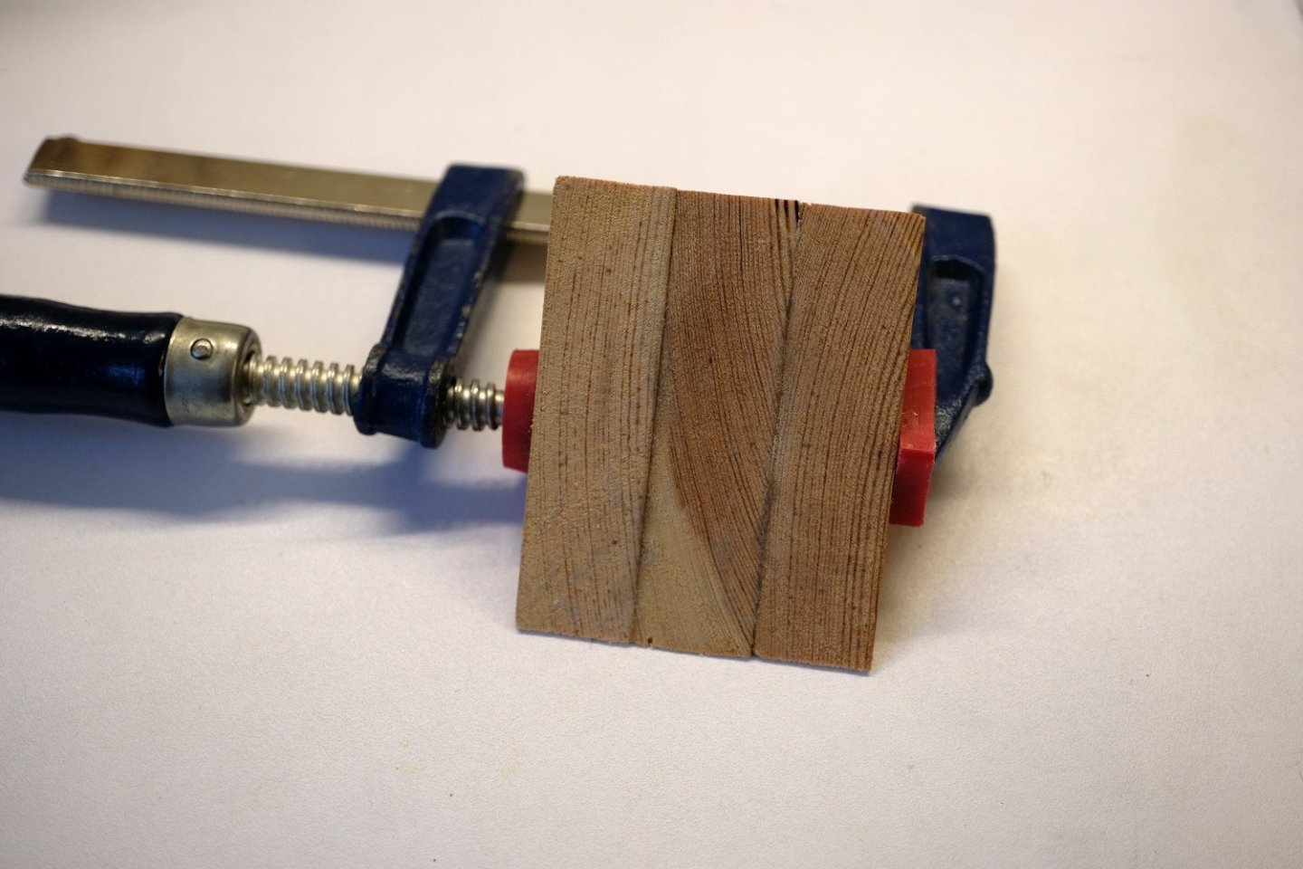
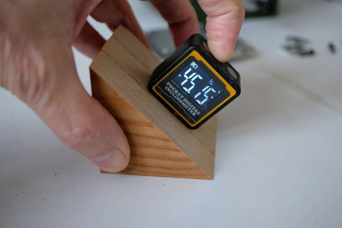
Hello All, As announced work on the tilting table now concentrates on fixing the bad alignment of the pins that connect the tilting table to the bearings. The ‘plan B’ is presented in the next figure. As you can see the 2 pins are replaced with 1 cylinder that is mounted to the tilting plate with a V-groove. The 1 cylinder will result in better alignment to the bearings. But that shifts the problem now to the fit of the cylinder in the V-groove. I have no equipment (larger mill) to make this accurate groove. So I will make it to the best of my abilities and use a clever interconnection technique to join cylinder to the tilting plate. First things first: the V-groove. I first removed both steel pins and then cut off a small strip of the edge. This is to assure that the new cylinder which has a 6 mm diameter will be in the same position then the former pins. Next is the V-groove that I will make with 2 saw cuts at 45°. For that I need a fixture to hold the tilting plate at 45°. The fixture is made of some scrap wood glued together and then sanded a bit. It is not perfect at 45° but will do. Then the V-groove can be sawn. The next close-up of the V-groove show that it is far from perfect. When the cylinder is pressed in the groove it shows small misalignment to the top or bottom of the tilting plate. Then I realise that gluing the 2 parts together can compensate for the misalignment on condition the I can position both correctly to one another. So lets start, the next picture shows all parts involved before gluing. I have 3 dowel pins that are ground accurate at a diameter of 3 mm. That is exact the distance between base plate and tilting plate in horizontal position, see the picture below. The 2 dowel pins under the cylinder will support both the cylinder and the tilting plate so that they are level. The 2 small plates at both sides of the base plate will align base and tilting plate. A weight on top covering part of the tilting plate and cylinder assures that everything stays in contact while the glue sets. As a last measure I put 2 calipers set at 73.1mm over tilting plate and cylinder at both sides. Now I hope I cancelled most sources of bad alignment. The whole setup is shown next. Now its time to take a break and cross my fingers. Best regards, Kris


- 4 replies
-
- 10
-
-
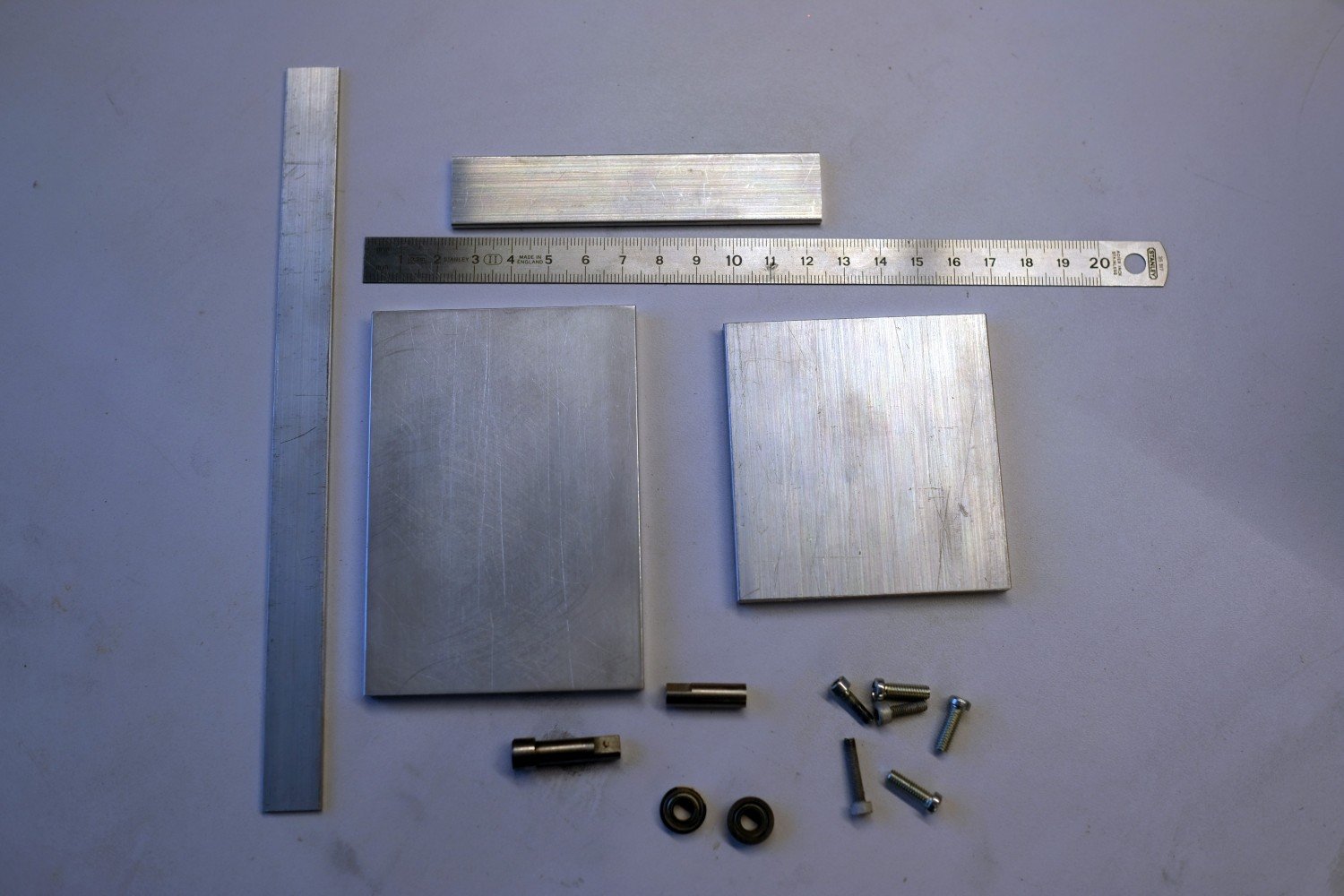
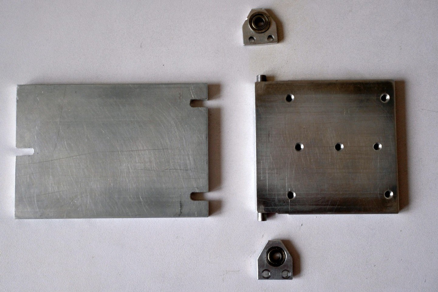
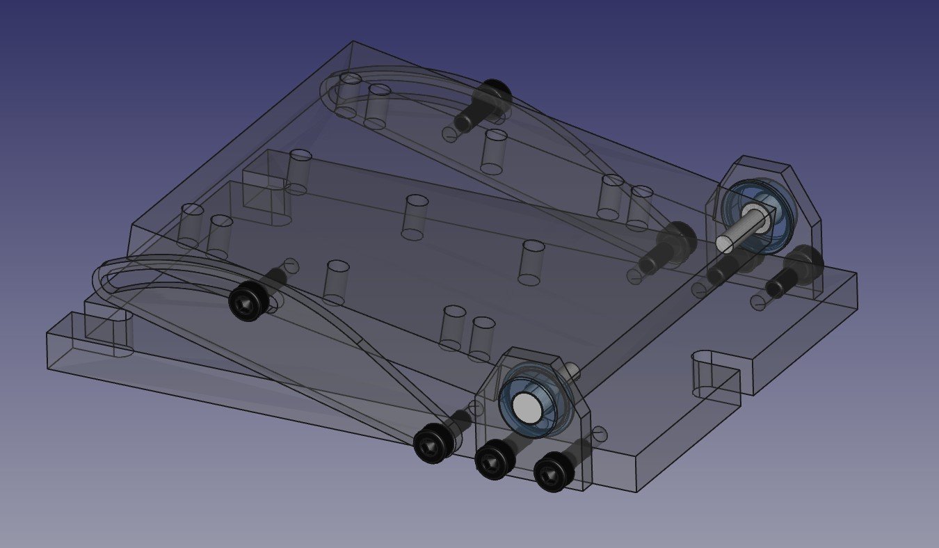
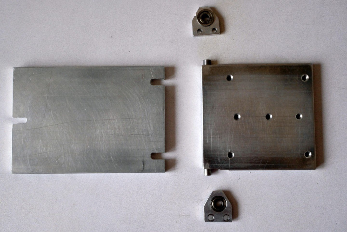
Hello All, This is my mini proxxon mill. It consists of a MB200 drill stand, a KT70 xy-table and a 230V ISB/E drill/grinder. I already added an extra z-control on top of the drill stand as you can observe in the next picture. Milling small wooden (or aluminium) parts to precise dimensions is possible but you must take into account that total run-out at the end mill can be up to 0.2mm. From time to time I need to do milling at an angle and I used to make small wedges to be placed under the workpiece. An example is shown next. It requires some calculation of the wedge dimensions and precision sawing to get it right. The problem is that a next piece more often then not requires a different angle and a repeated effort to make the wedge. That is the reason I want a small tilting table on this mini mill. Looking around on the internet, I could not find any suitable solution for such a small mill. So I started my CAD program and tried to design something that would support the MS4 machine vice at an angle. See below an animation of this design. And here is a view with all parts made semi transparent. So I started construction. First ordered some aluminium parts of different sections: 6x70 mm for a base- and the tilting-plate, 3x20 mm for the bearing-holders and 2x15 mm for the locking plates. The base and tilting plate were sanded to make the surfaces clean and flat. Then some machining followed: threaded holes for M3 and M4, 10 mm holes for the MF105zz bearings and 4 mm holes for the cylinder pins that connect the tilting plate to the bearings. Here you see some finished parts. These parts could be assembled and checked on the xy-table. While the result was quit good (< 0.1 mm over a 50x50 mm area) I could see that when tilted the tilting plate moves different left compared to right. That is because the holes for the cylinder pins are not positioned equal at both sides (see next picture). I already noticed that the 4 mm drill was wandering a bit to much at 1 side when making the hole. Also drilling the 10mm holes in such small parts is not easy to keep them at the wanted position. I tried to fix things by enlarging the M3 holes to 3.5 mm in the bearing holders. It helped a little but not sufficient to meet my requirements. So it is time for a ‘plan B’ to fix this. But that is for a next update. best regards, Kris


-
Kris Avonts reacted to a post in a topic:
Armstrong Frederick Cannon by allanyed - 1:24 scale
-
Kris Avonts reacted to a post in a topic:
Armstrong Frederick Cannon by allanyed - 1:24 scale
-
Kris Avonts reacted to a post in a topic:
Armstrong Frederick Cannon by allanyed - 1:24 scale
-
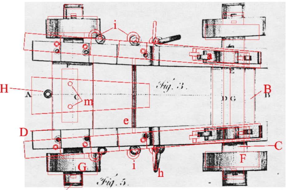
Just as a check for the angles, I made a superposition of the top view in the pdf document over a contemporary drawing of 1775 (see post #8 in the 'Gun Carriage questions' thread). The image from the pdf (red colour) was scaled, respecting the ratio, to align both wheel axles. The comparison of the angles seem to give evidence for druxey’s observation. best regards, Kris
-
Hello James, I just tested the fix and it all works again. Thank you and best regards, Kris Avonts
-
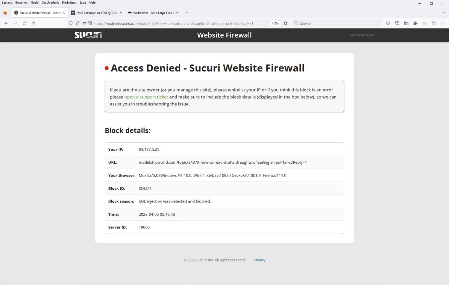
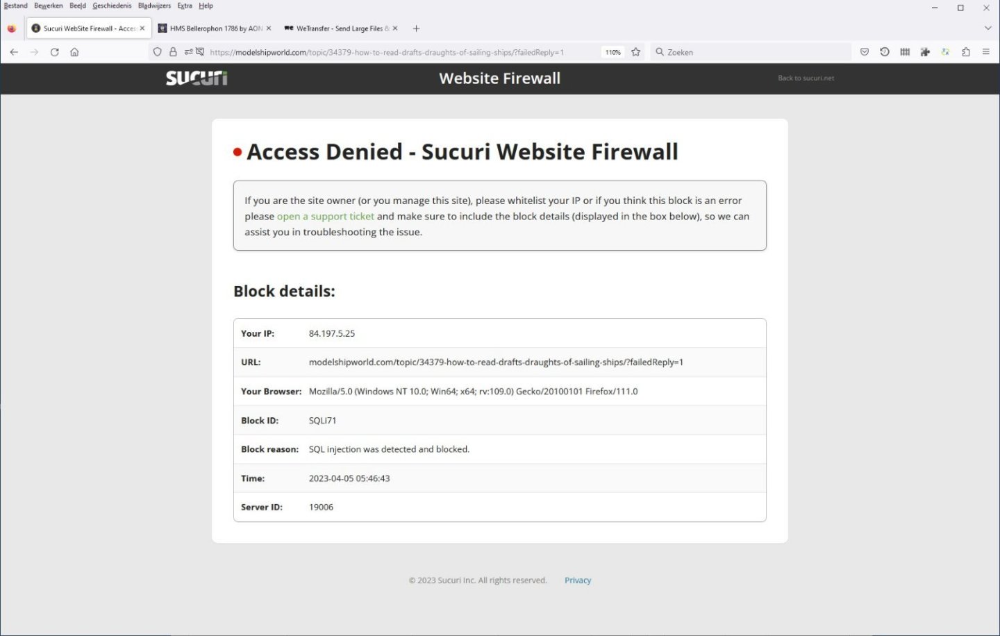
I get an error when I wanted to make a reply to a post. This reply had a link tin it to a previous post I made in October 2022. After pasting the link, it was replaced by a picture of part of that reply. When I hit 'Submit Topic', I get 'access denied'. Its a firewall issue: Any help to avoid this is appreciated. Best regards, Kris Avonts
-
Hi Gary, I went to a local printing shop and asked if they could do binding with metal rings. I was lucky they could do that. It requires some special tool that can insert the perforated sheets in this metal ring. I prefer this binding because you can open the document at any page and it will lay flat on the table. I hope you can find a shop offering the same binding system. best regards, Kris
-
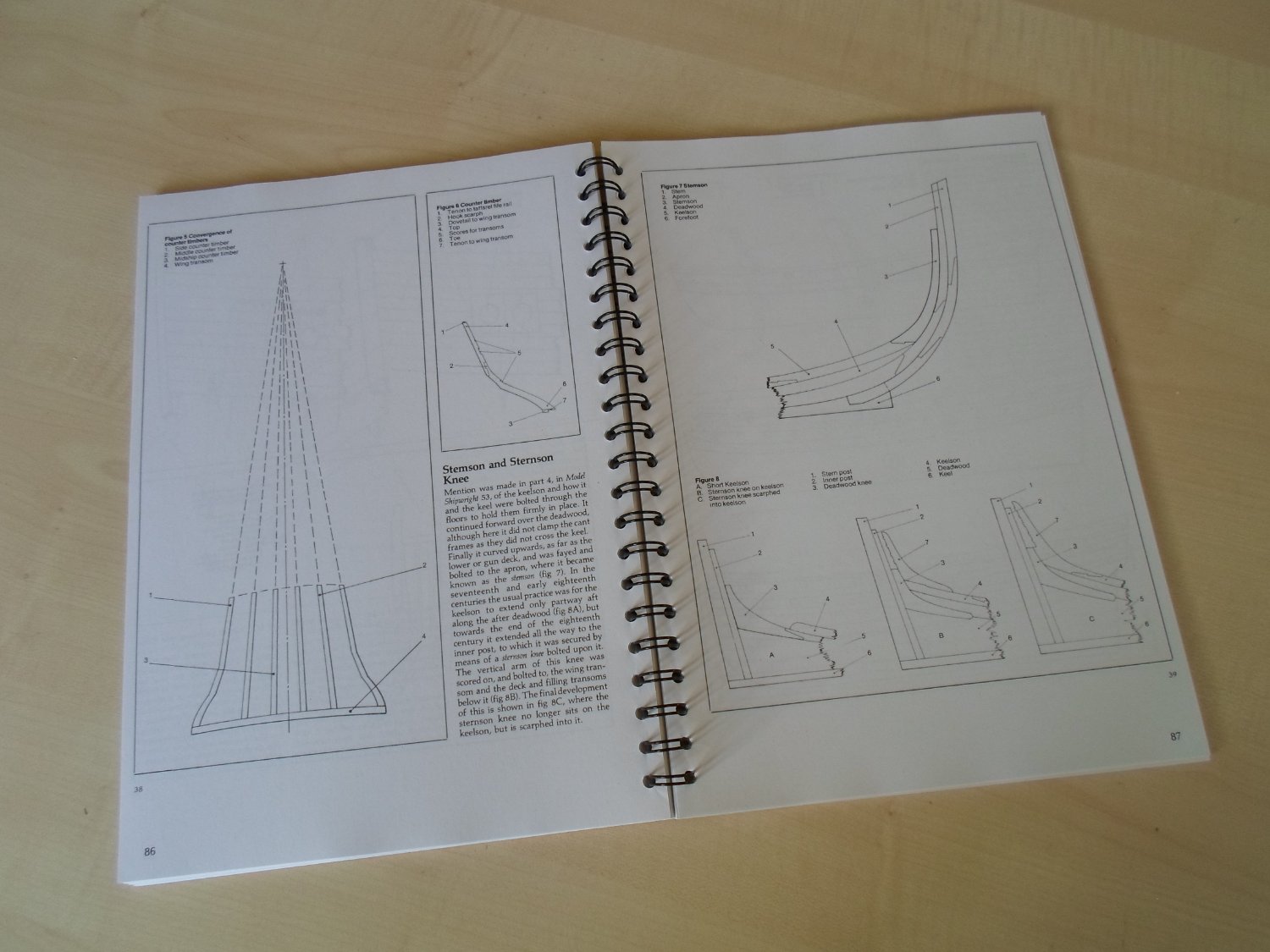
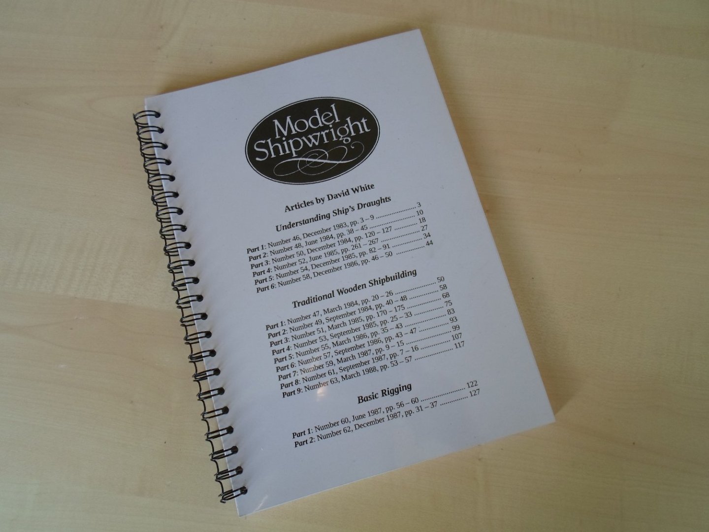
Hi Alan, I once scanned all the articles written by David White and published in the Model Shipwright magazine. They are an invaluable treasure for information on 18th century shipbuilding. The scans are bundled into a pdf document and I printed it out to have it on my workbench. See the next 2 pictures that show the result. If you are interested in the pdf, here is a link where you can download it: https://we.tl/t-kKyChhdXqo This document is made and intended strictly for personal use. I hope you can find good information in it. Best regards, Kris

-
Hi Ben, For you and anyone interested I can share the python source code. There are some comments written in the code file that can explain the order of things and the calculations done. If you encounter difficulties or other unclear parts in the code you can always send me a personal mail. This is the code file: ship-plan-adjuster.py best regards, Kris
-
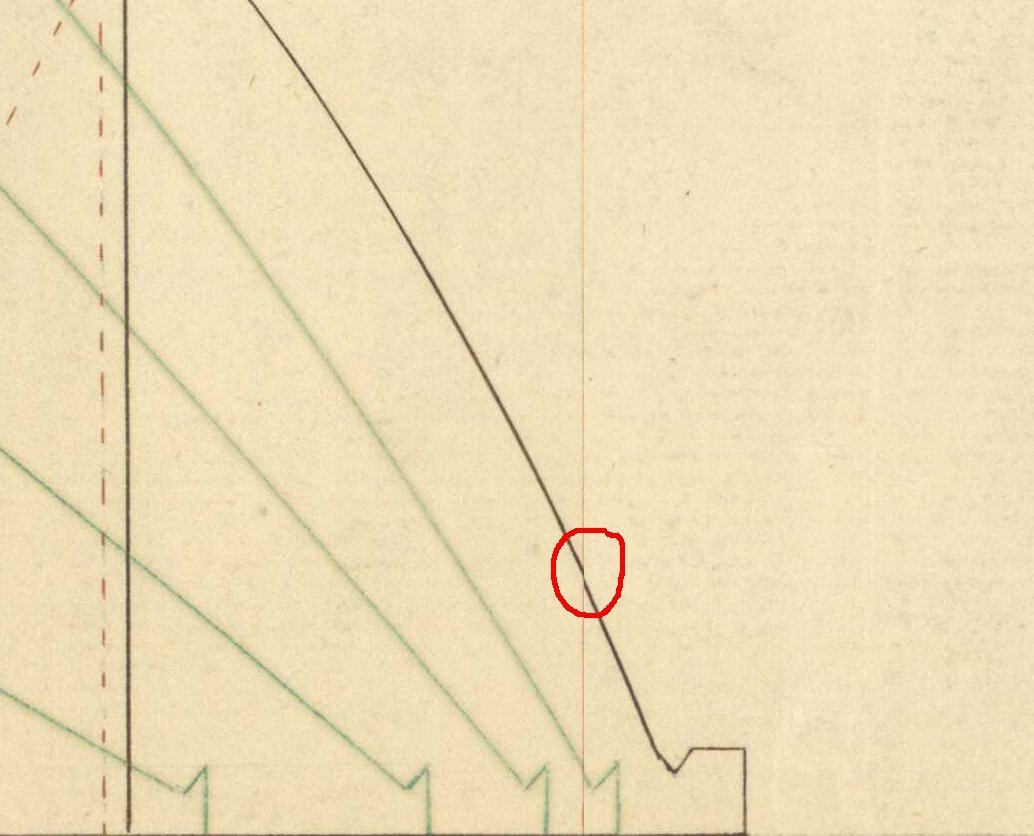
Hi Ben, Thank you for the appreciation of my image transformation program. It is however less advanced than you might think. I like to keep things as simple as possible but still try to reach the target I have in mind. A checkerboard correction method would only be applicable in the sheer view where you have the waterlines that should be straight and equidistant. The complexity of the transformation would become much higher and have no effect on the half-breadth plan where the waterlines are most important to give a representation of the ship's lines. Only when you could combine the intersection points of waterlines with station-planes of all 3 views (that is a lot of points) to map exactly on the same 3D point (most often called a vertex) by a transformation it makes sense. I think that is best solved in a 3D modelling program. @druxey, the ship plan scans of the RMG are such high quality, I think there is very little lens distortion. The paper distortion is more a concern and very difficult to correct due its irregular nature. I use my own transformation program to get the 3 views out of a ship plan and have them properly aligned before importing into a 3D drawing program. The workflow to make the transformations is important as I noticed in this detail of a half-breadth plan. I always try to analyse what could cause such artifacts. In this case it is not a bug in the transformation program but just me wanting to do correction of the half-breadth plan in just one go (single warp transform) instead of a 2 step square and warp transform. So you need to plan carefully the steps to follow, certainly when reusing results from previous transforms in other views (sheer in this case). best regards, Kris