Search the Community
Showing results for tags 'Rigging'.
-
Hi, The kit is Mantua/Sergal CS. The kit has metric measurements (not a problem) but for the length it reads like this 0.25 by "60mt". The only time I've seen "mt" used was for metric tons or MT. for mountain. Can anyone help me with this? I had trouble with math in school but that is a different topic. According to a number of resources CS would have flown a "Red Ensign" being a merchantman. The flag supplied is a Union Jack. Any leads for cloth printed small flags would be most welcome. Happy Thanksgiving to all...
-
 I am currently building the Cutty Sark by constructo. This is my first model ship and I think I am over my head, but I do have the hull all built and the masts an yardarms installed. I think all that I have left to do is the rigging and the sails. I am not sure of the best sequence to finish this project. Do the sails go up first or is the rigging and sails installed simultaneously? Is there a good book available yet details a step-by-step procedure for completing this task. Any help or suggestions would be greatly appreciated. cmb
 -
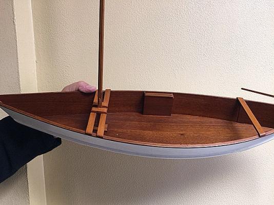
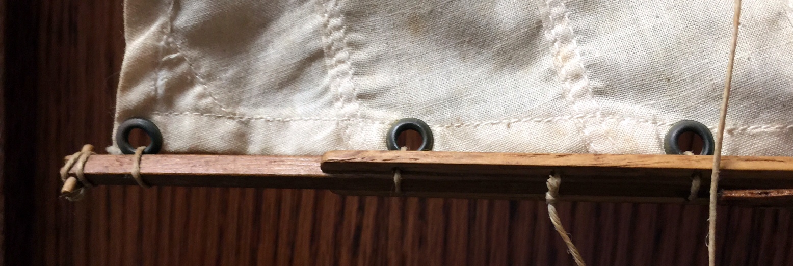
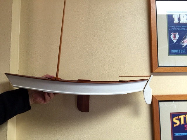
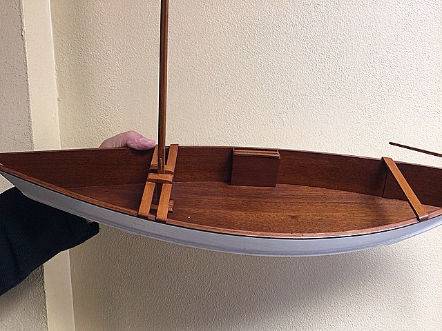
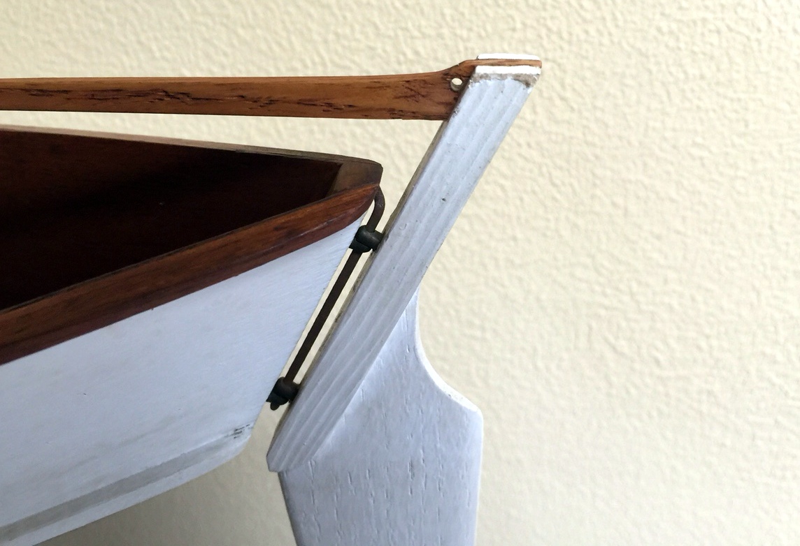
Hi - My husband and I are trying to figure out how to attach this sail to the mast. My father built this sailboat a long time ago and my stepmother gifted it to us after he passed. We had it on display until a gust of wind came through the house and knocked it over, breaking the boom. We took the sail off to get the boom repaired. Unfortunately, that was about 10 years ago. Now that we have repaired the boom, we can't figure out how to re-attach it. I'm attaching photos and really hoping someone here can help us. My stepmother is visiting next week so we would like to have it back together by then. Thanks for your help - Kathy

-
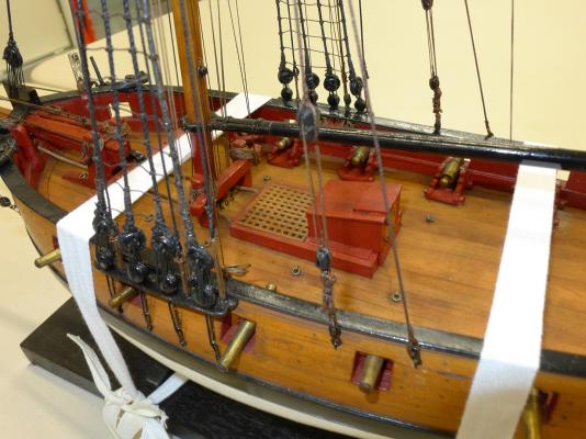
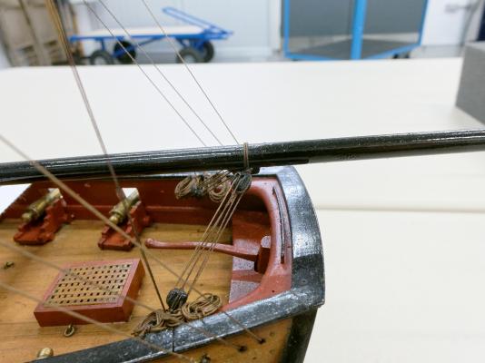
Hi folks, I'm thinking ahead to the rigging phase for the HMS Fly. I realize that serving protects rigging from rubbing. The question is, do I serve just at the upper part of the shrouds around the mast or all the way down to the deadeye. Same question for stays. Thanks in advance for any direction you give.
-
Hope this isn't a silly question. Can anyone explain to me how the clueline and sheet are 'tied' together on topyard and topgallant when no sails are present?
-
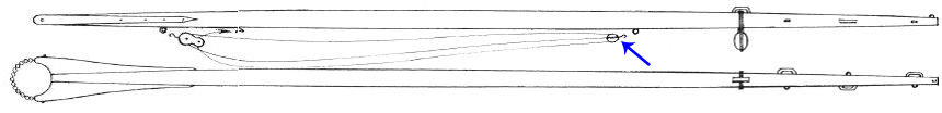
 In his book on Rigging Period Fore and Aft Craft, Petersson shows a diagram of a boom as follows: The arrow I have added shows some tackle fitted to the underside of the boom, quite separate from the mainsheet tackle (which is given the honour of a full diagram later), but there is no other mention in the book or diagram of how this might be used. I'd be very grateful if someone could explain it to me or give me some idea of its function and the points to which it might be fixed. Oh, and by the way, I'd also be glad of some explanation of the function of the bees at the end of the boom as displayed (just to grab as much info as possible in one swoop!). Thanks in advance for any ideas Tony
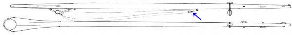
-
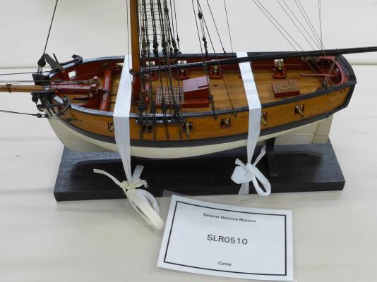
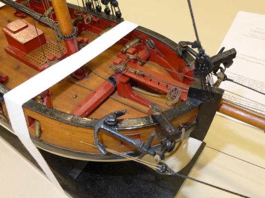
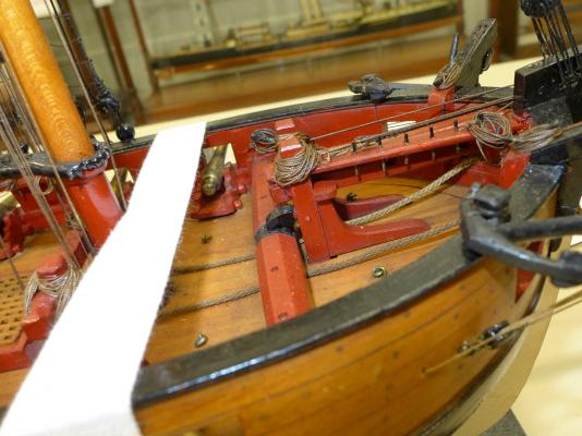
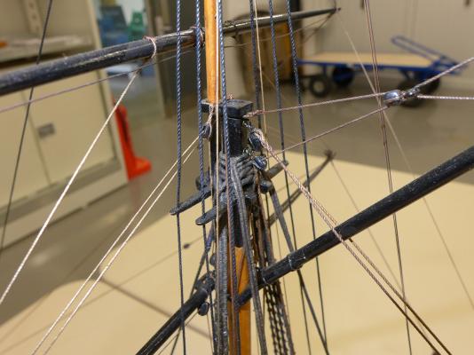
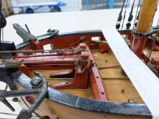
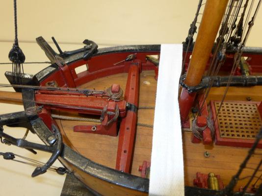
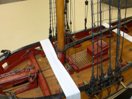
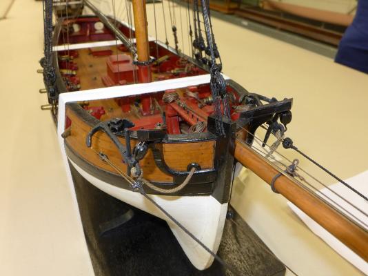
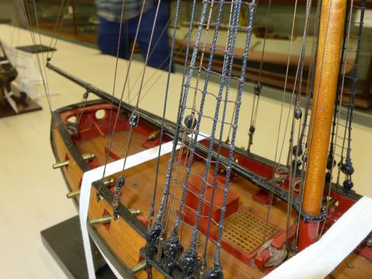
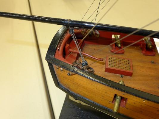
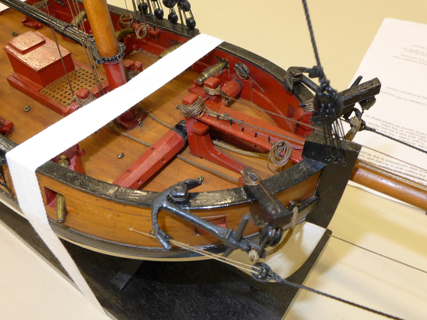
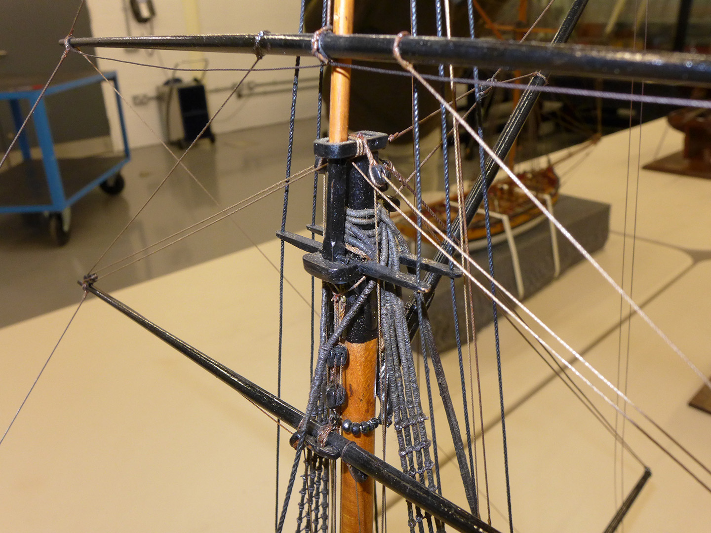
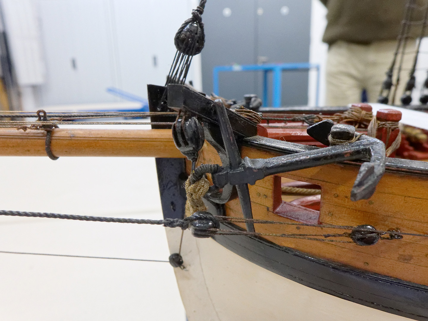
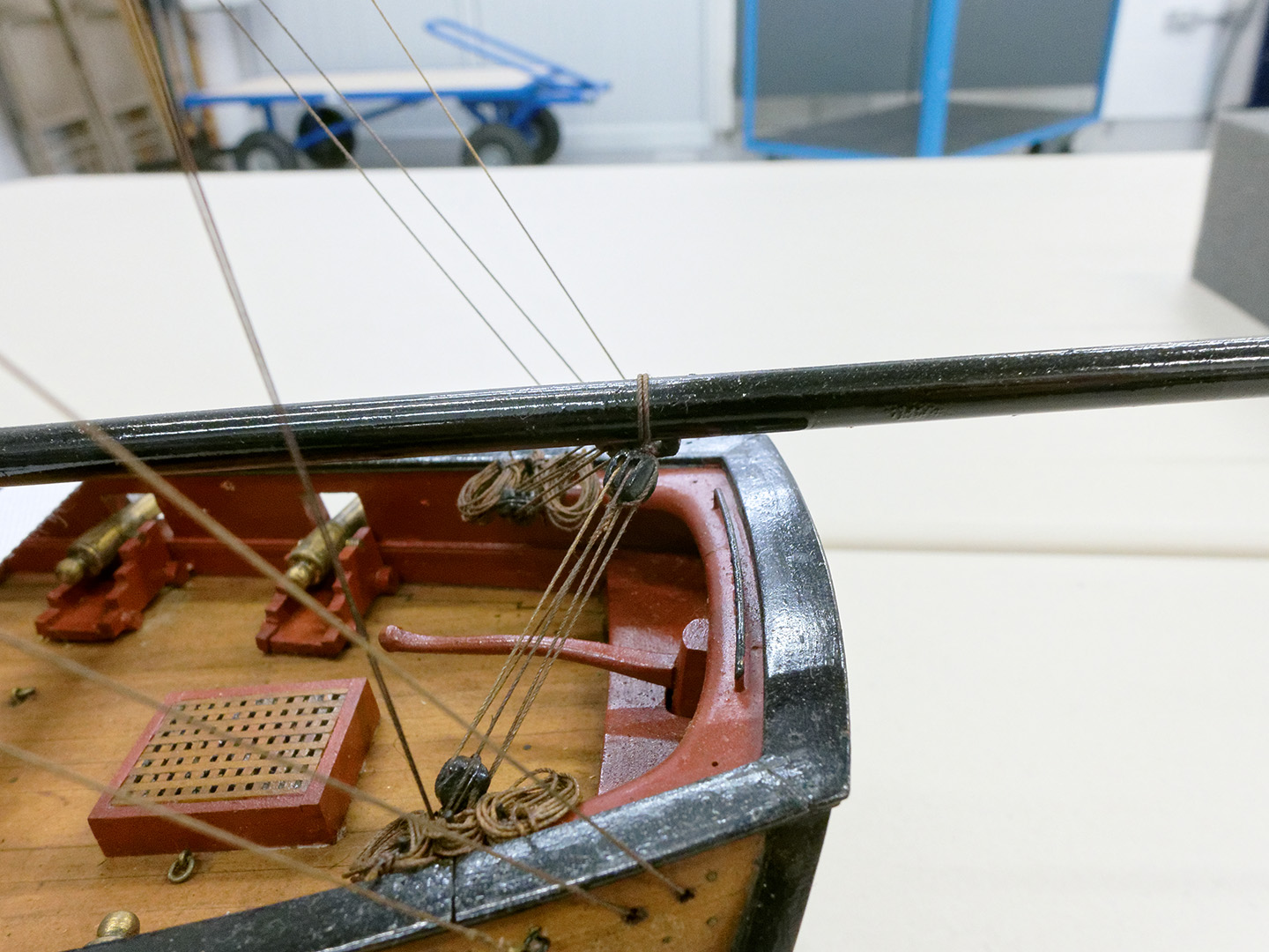
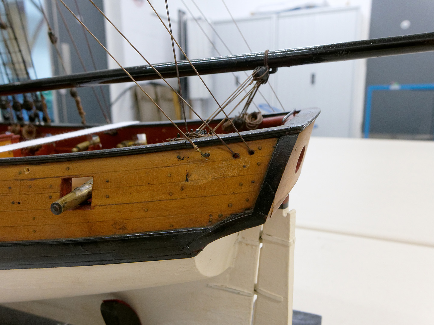
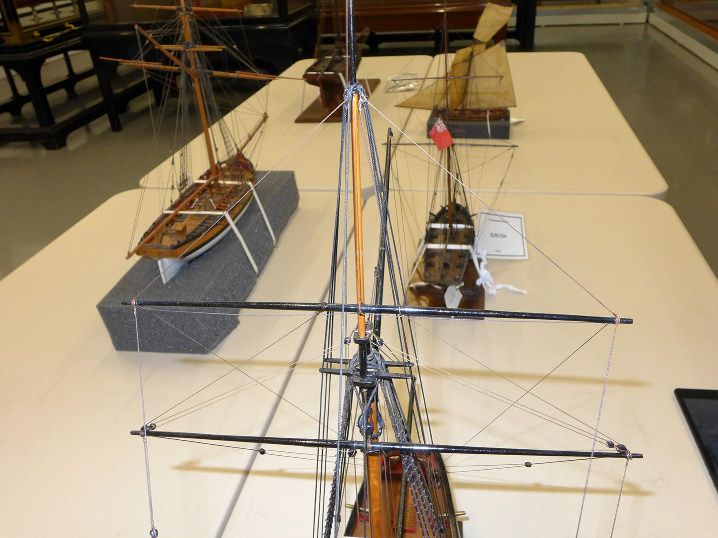
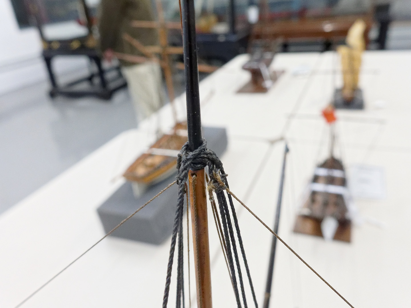
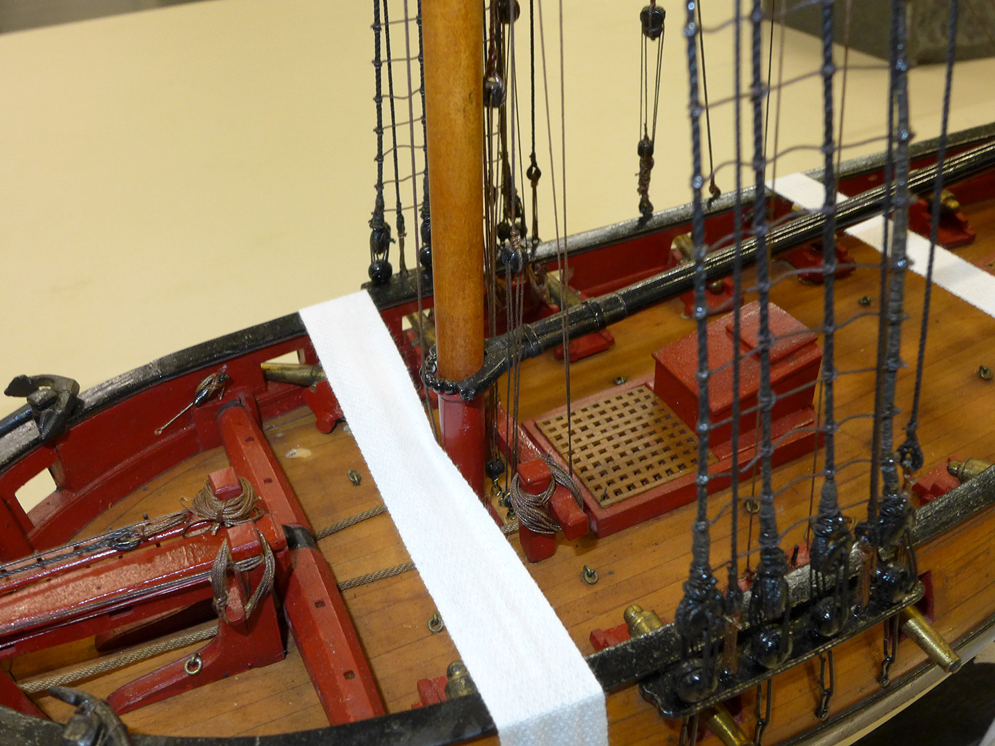
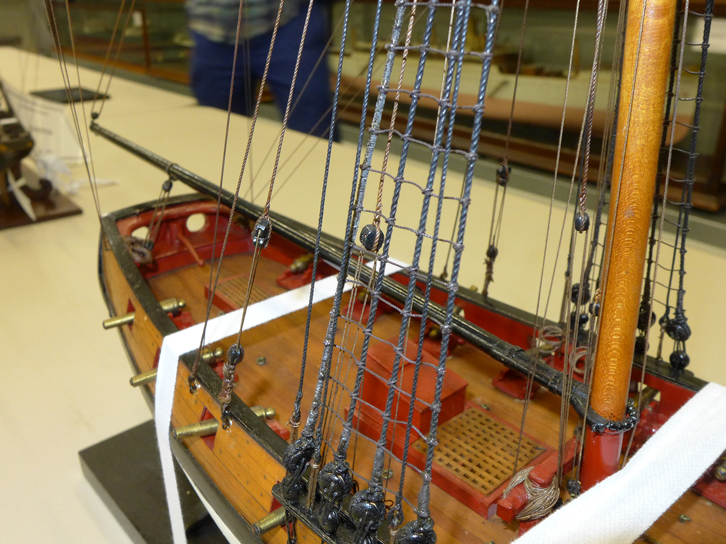
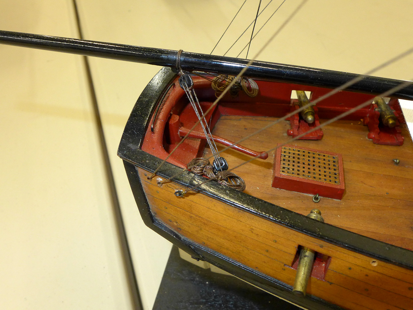
In order for me to understand better the rigging practices for cutters of the 18th Century, I wrote to the National Maritime Museum asking if I could see some of the cutter models they have in storage, now that they no longer have a model display at the Museum in Greenwich. Nick Ball, the Assistant Curator of Ship Models, wrote back very quickly saying that I would be welcome to visit and could see all of the models I had requested which are now stored at the Royal Historic Dockyard in Chatham -- except for one which was stored in another location less accessible to the occasional visitor. He, together with Dave Lindridge the Store Manager, gave me a very generous amount of time to look at and photograph the models that they had taken out for inspection – during which they provided a lively discussion about their jobs and the models they were showing. In fact Nick said he was pleased to show visitors the models because it gave him more of an opportunity to review models in their vast collection. I asked Nick about permission to post my pictures and he told me it was fine as long as I made it clear the pictures were from the NMM collection. He also asked to be provided to the links of the photos as he himself (as a trained naval archaeologist) was very keen on the details and would enjoy any discussion that ensued. I will post the photos of the individual models under different messages, this post deals only with the first of the models. I just need to add that I am enormously grateful to Nick and Dave for their patience and generosity with their time for this visit, which for me was invaluable. 1763 cutter NMM ID SLR0510 First off is their cutter referenced in the NMM as Object ID SLR0510. It is described there as “a full hull model of a cutter (circa 1763) Scale: 1:48. The vessel measures 53 feet on the main deck by 20 feet in the beam and is armed with twelve 3-pounders. The model was donated unfinished and was completed in the Museum in 1960”. For me there were four main points of interest, apart from the fact that it is dated the same year as my Sherbourne. The first is that the fore belaying pins are arranged fore-aft beside the bowsprit. Gregor, Dirk, Kester and I have been trying to figure out how the belaying pins would be set given that the kit of the Sherbourne provides no plans for such a belaying rack. Each of us have provided our own particular possibility – with Dirk going for an arrangement such as that on the AOTS book of the Alert, and Gregor going for a rack right on the stem. I had made a rack that was parallel to the windlass. However, now I have seen the arrangement on the NMM cutter SLR0510, and, as you will see, the 12-gun cutter I saw had the same arrangement, I have changed my own rack accordingly. The second is that the topmast is fore of the main mast. I had understood that earlier in the century the practice was to place the topmast aft of the main mast. In fact the cutter Hawke (which I also saw at Chatham and whose pictures follow in a subsequent post) was the only one of these models to place the topmast aft of the main mast. The third point of interest was the windlass. The original NMM plans for the Sherbourne showed this type of windlass, and Gregor has already made one in the same style, and I followed his example – rather than following the type of windlass provided for in the Sherbourne kit. The fourth point of interest is that, like the Trial that you'll see in a subsequent post, the lower hull is painted up to the wales, and not to a waterline. The following were the other pictures I took of the1763 cutter, all of which will have details which will be picked up by those more knowledgeable than I am! Tony


- 42 replies
-
- 22
-

-
- Cutter
- 18th Century
- (and 4 more)
-
These might be posted here already but I found them very helpful with the rigging on my Byzantium. The Elements and Practice of Rigging and Seamanship Boy's Manual of Seamanship and Gunnery Lextin.
-
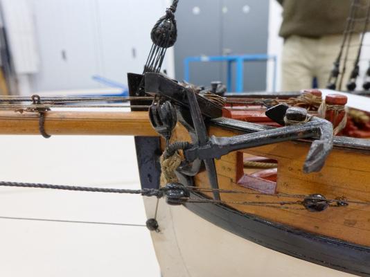
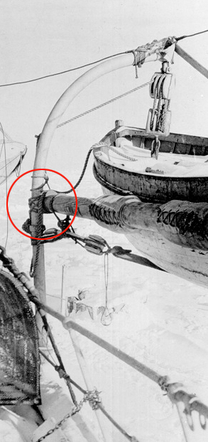
Any thoughts on the attachment of the strong back to the radial davits on the Endurance? This was the ship Shackleton used for the 1914 Antarctic expedition. Is it only lashed to the davit or is there a mechanical attachment? I can't make it out. I have a pic attached showing the area. Thanks, Terry PS Posted this in General Kit discussion in an old thread. Thought it may get an answer here. Thanks

-
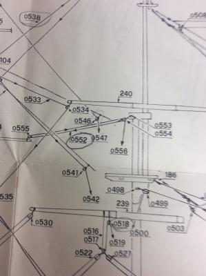
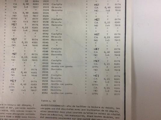
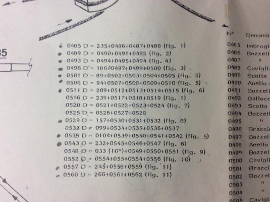
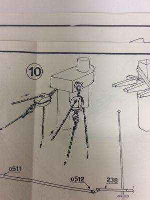
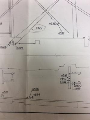
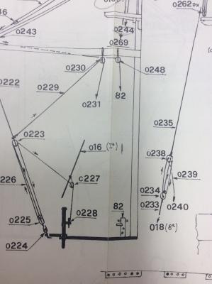
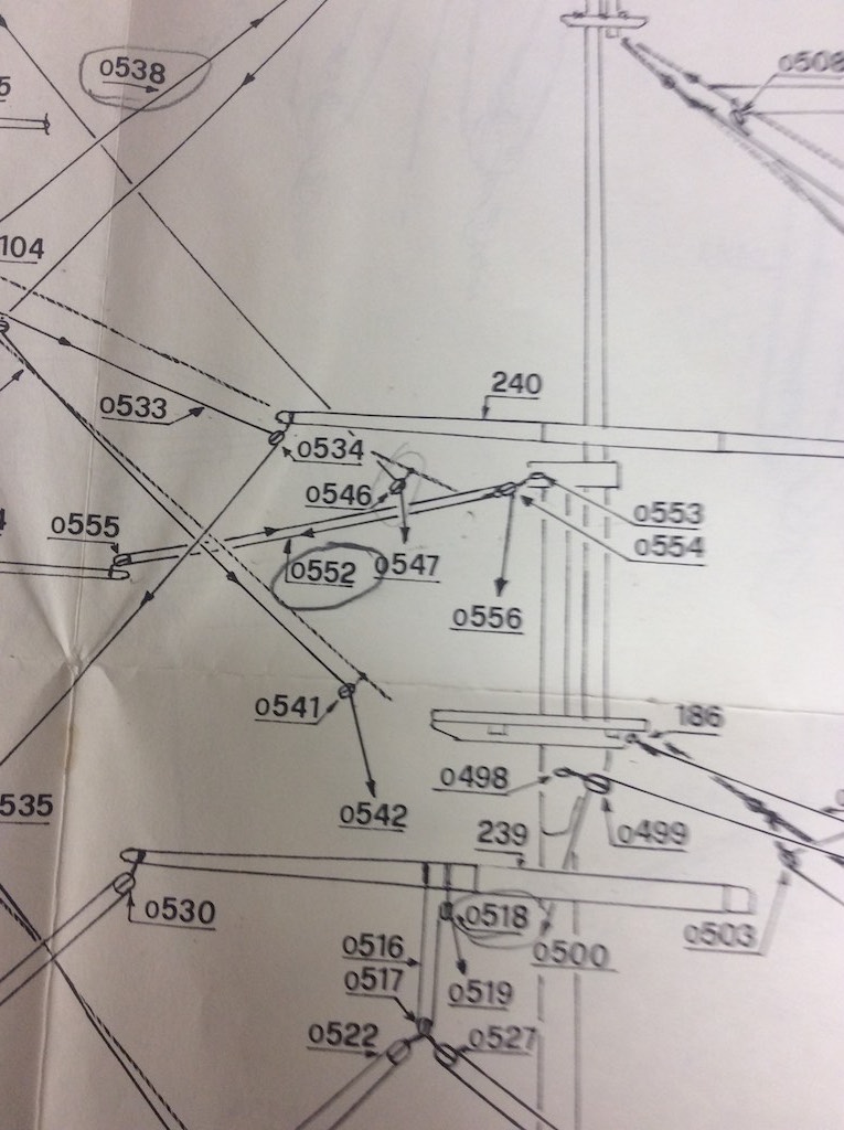
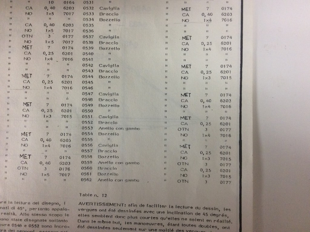
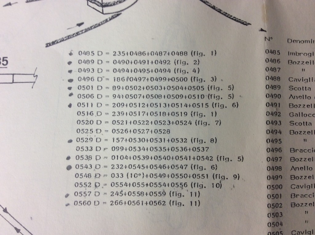
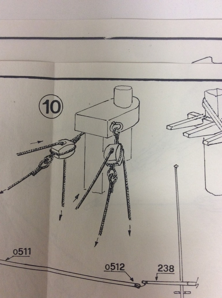
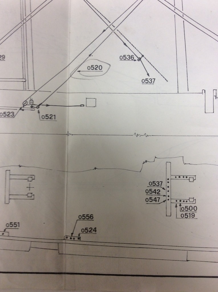
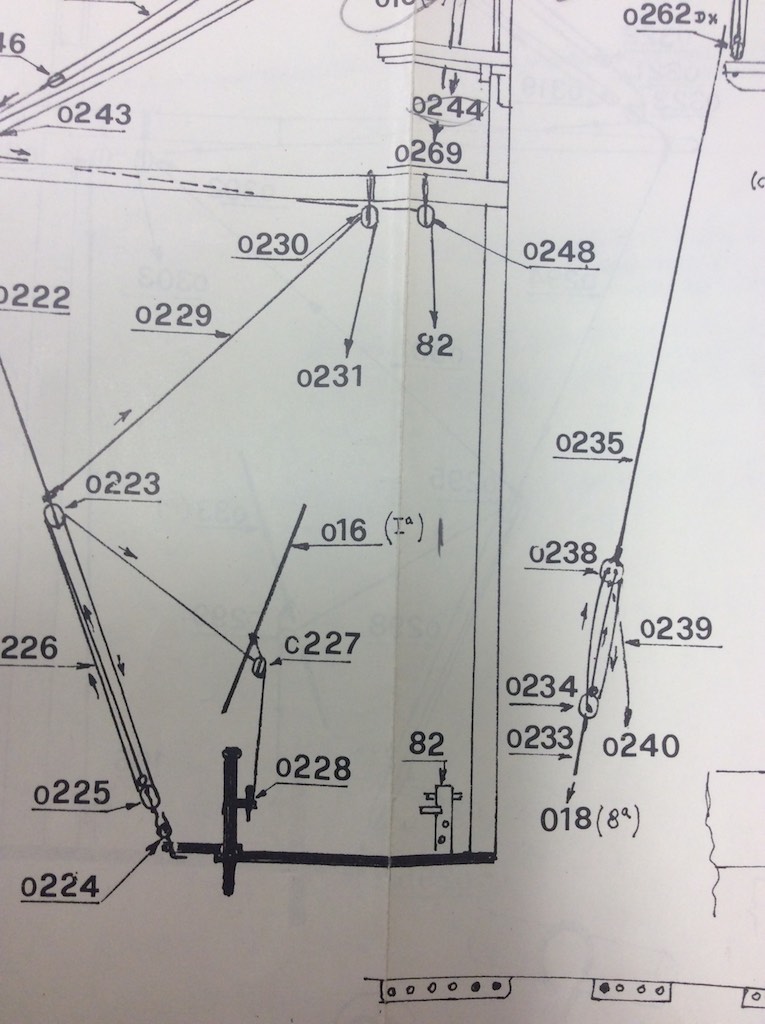
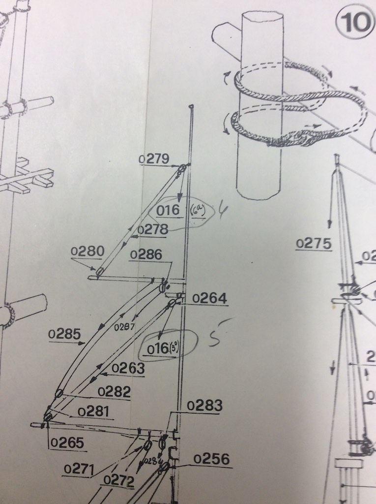
I spent quite a bit of time learning how to read the Mamoli rigging plans. Since there were no explicit instructions on how to interpret the drawings I spent a great deal of time looking through them before I figured out their method. Once I did, it was pretty straight forward. I thought perhaps others might find this useful. Perhaps this is how all rigging plans are done. Since the Connie is my first kit, I have no reference. I also need to mention this kit was purchased in 1991 so it may have changed. However for what it is worth here is how my plans are interpretted. There are two tables on each rigging page. The first table is on the right and lists all the parts, this is standard on all the Mamoli pages. However the second table, placed directly to the left of the first left is only on the rigging pages. the tables are not really labeled or numbered but they are consistent on how they arrange them. The only difference is where they are placed on the plan. For this illustration I will show how to interpret the rigging on the Mizzen (part o552) circled on the drawing. Here is a copy of the appropriate section from the plans: This shows a rigging set running from the tip of one of the Mizzen booms to the cap just above the Main Mast's fighting top. First we need to see what the parts are for this rigging. The size of the line, the size of the blocks, etc. For this we turn to the right most table on the plans. This table is on all of the plans an lists the all the parts of the ship as well as the various sizes. In some cases, the part number might refer to a different page of the plans if the part was installed much earlier so you might have to refer back to another page of drawings. Here is a copy of the section in the table dealing with the rigging for this piece. We can see here that 0552 (o552 in the above drawing) is labeled Braccio (which means "Arm"), the second column tell us that the amount is the same as the above parts, which is 2, although you can't see that in this photo. More importantly, the second column from the right says 0,25, which means this is the 0.25mm line. So now we know the size of the line, let's see where it runs. The second table directly to the left of the parts list table contains the order a line runs by listing the part numbers in the order they go starting at the lines termination in the rigging and ending at the termination on the deck. The entry for 0552 shows 0552 D = 0554+055+0554+0556 (fig 10). This is chock full of valuable information. Ignore the pencil marks, that is how I track when I install a line. First the line will start at at part 0554. We can look on the first chart and see 0554 is a block (Bozello) that is made of walnut and is a single 4mm block (1x4). This also refers to a figure (fig. 10) for more information. This figure is shown below: This shows the manner the blocks are attached to the mast cap. If we want more information on the rings we can refer back to the first drawing of the rigging and see this part is 0553. Referring back to the first table we can see that part 0553 is a 3mm brass eye ring (Anello con Gambo = Ring with shank) the OTN refers to a table in the general instructions that shows it is made of brass. So after the two rings are installed on the cap, the block is added with the .25mm line attached to it. This then runs to the block 0555. The table tells us this is also a 1x4 walnut block that is attached to the end of the spar. The line then returns to 0554 and runs toward the deck. As a note here, if the line also went through the fighting top, that too would have been listed in the order the line ran through it. In this case it does not but goes directly from the block (0554) to part 0556, which table 1 informs us is a belaying pin (Caviglia). The termination point is shown not only in the table but also in the rigging diagram. The sheet also has a diagram showing the layout of the termination points when viewed from the rigging. From this we can see that 0556 is the third belaying pin aft in the 4 pin belaying rack located on the starboard side between the two fife rails. The port side has a matching set for the matching mirrored rigging set. So that is it. A further note on terminations, if a line terminates tied to a side shroud, the shroud grouping is noted and it is numbered from front to back. So the rigging drawing would show the shroud set from the side and give you the number it would be referred to as. This would look like the following: Any lines terminating on one of these shrouds will be labeled 16(x) with x being the number of the shroud from the bow. The following drawing shows how this shroud is referred to int he rigging drawing. So this shows the top line would terminate on shroud set 16 on the 6th shroud. The one below is marked to terminate on the 5th shroud. It is hard to read but you can see my pencil marks to the left of the number. So this is how the rigging plans work. I stopped working the lines from the top of the table down since they tended to number the lines from the bottom up. This meant that the top lines which normally run down the center of the ship, had to be fished through the other lines. However, other than that, I have ben following these diagrams pretty much as they are drawn. [ dia=core:attachments:202725]

-
 I have seen many references to " dilute CA". What is the diluting solution? Is there a prefered ratio?
 -
I was wondering if there were any advantages or problems that anybody has encountered with regards to doing the standing rigging after all the running rigging/sail hanging has been completed. I looked through the instructions and it seemed easier, to me at least, to do all the running rigging before the standing. Currently working on an AL 1:75 Bluenose II
-
 Roy - Bill - Jason - Barry - Tom - David - Ken - Jim - Tom - Larry The SMS-NJ recently had a custom Admiralty Models workshop on rigging. This very successful 2 day event was hosted by one of our members at his house. We covered a lot of the same ground as their most recent workshops in Baltimore and NOTL but also added some custom material tailored to our needs. Everyone came away from this workshop with a deeper understanding of advanced rigging techniques. Having the workshop locally enabled attendees to save the cost of hotels and restaurants. We have been advocates of David and Greg since the very beginning because of their ability to make difficult modeling concepts more understandable to ship modelers of all skill levels. In our group we had modelers that are working on their very first kit, others that are kit bashers as well as several scratch builders working on ships like the Warrior and Liverpool. If you are looking to advance your modeling skills you owe it to yourself to check out Admiralty Models. If you are a member of an active club with members that would like to better their ship modeling skills contact Greg or David about a custom workshop in your local area.
-
- 6
-
-
- Admiralty Models
- SMS-NJ
- (and 4 more)
-
Hi all. This is my first post but I've read lots. I'm working on my second boat and I'm almost to the rigging phase. My first boat was the Mississippi queen so I didn't need much help with rigging. I'm currently working on the AL San Francisco II. Basically what suggestion would you guys have as far as usefull tools. I have a solid background with wood and haven't struggled much with the woodworking part but I'll be honest the the rigging is intimidating. Also any suggestions on tapering techniques for the mast would be greatly appreciate. Johnny
-
I came across yet another question that I have concerning the specs for "bucklers", specifically, "hawse bucklers." These were used to cover the hawse openings when the ship was under way in heavy seas and obviously, when anchors were heaved and secured. My question is simple: what do these look like? How were they secured to the hawse openings? Did they have a gasket to seal them? Made of wood - or metal? Thanks Mates.
-
I am looking for a model to learn about rigging techniques. I am building 2 ships now but want to practice rigging before I get to the real thing. Any suggestions would be great. I was thinking of a model with the hull already done I just need to start on the masts and the rigging. Thanks in advance. Brad
-
I'm new to building wooden model ships and I do not want to use a kit. I have build my rope walk but I need to know the different diameters of rope on the USS Constitution, but I can't find that information. Can anyone help, please!!!!
-
 Several Questions: 1 - What are the rules of the amount of serving a line/rope? 2 - How do you know which vertical line on a ship needs to be served, and how much? 1/2? 3/4? I know it depends on the type of ship, what country is it from and what century. But are there some general rules and are there any books available. I looked in some of my books but there is no details. Several people on this site mention Steele (sp). I have looked at many models on this site and others and it gets confusing. I like to be accurate about all the models I make. Thank you, Marc
 -

Correct hitch and advice on rigging a flag needed
Gabek posted a topic in Masting, rigging and sails
Hello folks. I'm almost done my first wooden build - AL's 'old' Swift - and I'm getting frustrated with the rigging. The plans and directions aren't much help in what knots or hitches should be used anywhere. I've been forced into doing lots of research (I have Lever, Longridge, and perhaps a dozen more books), which is ok but I can't seem to find a hitch or stop that would be used to attach the *middle* of a rope to a ringbolt. In this model the throat halliards are tied to ringbolts on the deck. With gaffs fully raised on the masts there should be a lot of rope on deck, and I'd like to tie off that line in a logical manner. The closest seems to be the slippery hitch - but was there a 'right' one? A second rigging question is about the flag. Did flags in 1805 American ships have grommets? Were toggles used to rig flags at this time? I'd welcome any advice on how to attach the flag to the halyard. By the way, does anyone who has built this model think that the rigging is haywire? Seems very illogical to me. Thanks! Gabe "So happy to be a part of MSW" K. -
This post is intended for anyone who has built, is building, or is contemplating building HMS Victory, whether in kit form or scratch built. Others with an interest in Rigging generally may also like to chime in. I've come across an interesting conundrum regarding the rigging of Victory that other Victory builders may be interested in. I spent several hours poring over documentation to try and work out the use of Yard Tackle Pendants and Brace Block Pendants. I consulted several sources, but my primary reference for any assertions here is Longridge. I also sent a PM to Gil Middleton to seek advice on his approach to this aspect - his reply is posted within Gil's own log (as we had a problem with the PM system), so I won't repeat it verbatim here. First up, as far as I can tell, Yard Tackle Pendants are only used on the lower yards of the Main and Fore Masts. Longridge talks of these in the text descriptions for each of the yards, and this is matched by the drawing of the Running Rigging by Campbell (Plan No. 7 in Longridge). Secondly, I don't believe Pendants were used for Braces except for the Cross Jack Yard. Longridge specifically states (pg 258), in his description of the Cross Jack Yard, that "Here is the only place in the ship where Brace pendants are employed." I also checked over McKay's AOTS book, and as vague as it is, it does seem to match Longridge as well, with the exception that it does not show brace pendants for the Cross Jack Yard. I got terribly confused by all of this as Antscherl (in TFFM) employs brace pendants on all yards, and although he shows the Yard Tackle Pendants, he doesn't say much about them. The Mamoli kit plans, as bad as they are, actually do match Longridge (now there's a turn up for the books!), with the exception of the Cross Jack Yard Brace Pendants, and belaying of the yard tackle pendants. I got further confused when I looked back over Gil's excellent log, where he has employed brace pendants on all of the upper yards. So I asked Gil about his sources and choices. Gil's response was (in essence) that the Jotika plans showed them this way, and that this matches his photographs of the actual ship (see Gil's log for these photos). He opined that Longridge was basing his version on the 1922 restoration and that this may have been different to the more recent restoration to (supposedly) the "Trafalgar" state of the ship. Gil also quite correctly points out that different Captains changed rigs to suit there personal preferences, so unless we can go back and interview Captain Hardy, we might never know for certain. In the meantime, Gil has chosen to stick with the Jotika/Trafalgar restoration version, and I have decided to stick with the Longridge version on the basis that if Longridge is wrong, then I'm happy to be wrong with him. I've also been confused by the belaying of the Fore Lower Yard Tackle Pendants. Longridge, in the text (pg 242), is quite vague saying, "The pendant...is a 7-in rope with its lower end spliced round a 13-in double block which is connected by its 3 1/2-in fall to a 13-in single block which hooks on to an eyebolt in the side of the deck." In the diagram (Plan No.7) "the side of the deck" seems to translate to the Fore Channel, and this matches the drawing in McKay (pg 109), though neither actually show the final belaying point clearly. In checking the text again, Longridge's Belaying Plan (Plan 10, pg 266) and his Table of Belaying Points (pg. 270) both show that it belays to the "7th timber head, side of forecastle". But this raises another question for me - how does the line get to this belaying point without going through the shrouds/ratlines and/or the hammock netting and consequently becoming fouled? It would make more sense to me to belay it on the Fore Channel, outside the shrouds, as seems to be indicated by all of the diagrams. Does anybody have an opinion on this? For interest, general discussion and further opinions as appropriate.
-
 I found a topic on MSW explaining the "Frolich Style Rope Walk Plans" and there was links to: Version 1 Drawing # sheet 1 Drawing # sheet 2 Version 2 Drawing # sheet 1 Drawing # sheet 2 Unfortunately they are broken links and no further work. Has anybody got these sheets, if so would you be able to send them to me please as I really want to see them? I await your response> Thank you Barry
 -
Hi; Question: How do I decide what color rigging to go with? My Mamoli model the Royal Mary has all Tan line - do not like it much as the color is too light. My Bounty had black rigging and looked good. I see some models on this forum with shrouds that are black line for vertical and white line for horizontal. Did every century have different color line? Does it depend on what country the boat is from? Does it depend on the type of rigging? I always like to built my models historically correct, so who knows the answer, if there is one. Thanks, Marc btw. If my era boat is to have tan lines I will give it tan lines.
-
New to the forum, and what a help it is! I am building the San Franscisco ll, and I find the rigging info with the kit to be quite sketchy, to be polite about it. On the mast caps there are four holes for rigging lines to go over the cap and out the bottom of the caps. Just where do these lines get tied off? What is their purpose? The kit photos show the lines, but no mention at all of where to tie them off.
-
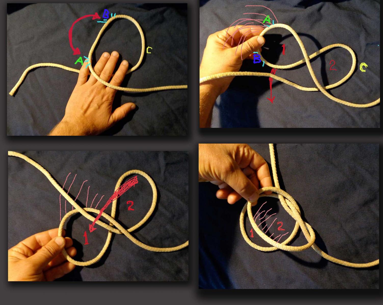
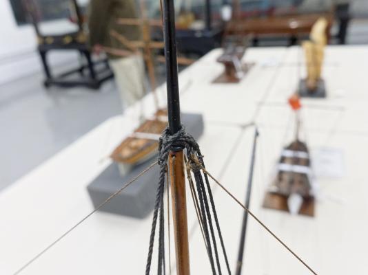
I’m a big fan of the Constrictor Knot. It’s a very useful knot for fixing a line to a spar such as in the case of a stay or backstay attaching to a topgallant masthead on small models or on lighter lines on larger models. Its got a low profile and its easy to tie and when tightened it constricts as advertised. Clifford Ashley apparently invented it and its number 1249 in his book. It’s also mentioned in the original Ship Modelers Shop Notes in a Merritt Edson essay on page 187. Unfortunately the illustration included in Shop Notes tends to make the knot look difficult to tie. In fact most descriptions of the knot fail to show how easily it can be tied. Its litterly just a loop that is twisted once into a figure eight and the two lobes thus created are folded together to form the knot which can be slipped over the end of the spar in question. If the knot has a drawback it is that once tightened it can be very difficult, if not impossible, to untie. This photo shows the steps involved in tying it and below I will break down the individual steps. It may appear complex but it really boils down to a few simple hand moves.

-
I'm finally about to start the running rigging (With Sails) and the first instructions are about connecting the rigging to the yards. Basically, the thread goes through a hole at the top of the mast and then somehow connected to the yard. What I don't see is, How the heck am I supposed to connect the thread to the yard? I'm assuming I just tie it on or is there some subtle part of the instruction I'm missing? Also, other halyard instructions for the other yards look like the rigging just goes through some blocks but never actually tie onto the yard. Is that correct? A large number of blocks were added to the yards in earlier instructions. I see in one part of the running rigging instructions where they note that fact and that the rigging should be done with those blocks. It seems like there are more blocks (I could be wrong) then there is rigging to them for those yards (for that one instruction part). And, there are tons of other areas where blocks are needed for other rigging all over the rest of the instructions. Is there an assumption that some of those blocks that were previously rigged would be used in those other instructions and not just the area noting their usage? Sorry, if this seems confusing, but if you've completed this any time recently, I think you might understand what I'm getting at. Thanks.


.jpg.d84ec4dad1d7791e855dca06210ab6f3.thumb.jpg.f45209242e851d4409eca1a09293165b.jpg)