Search the Community
Showing results for tags 'Rigging'.
-
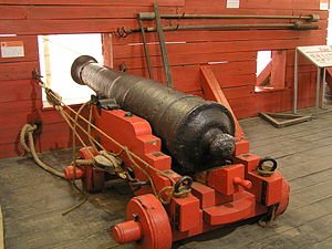
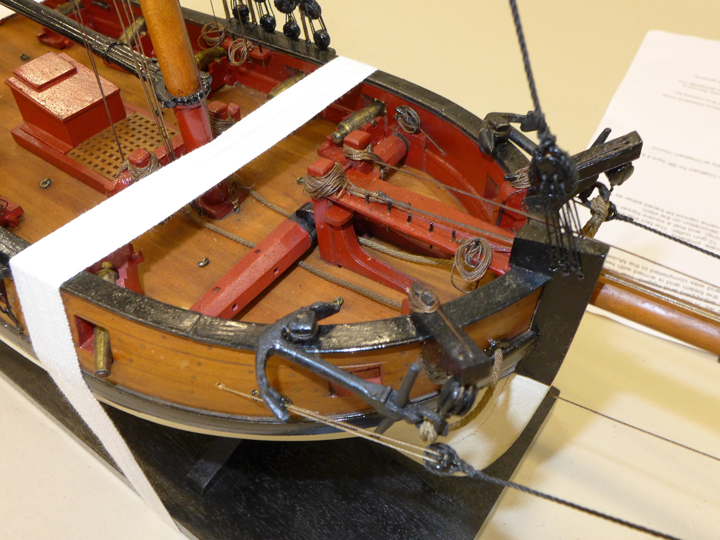
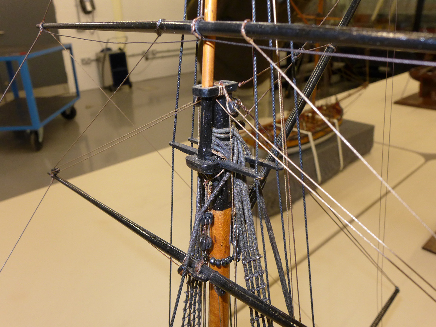
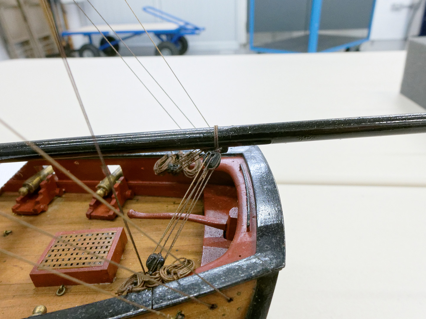
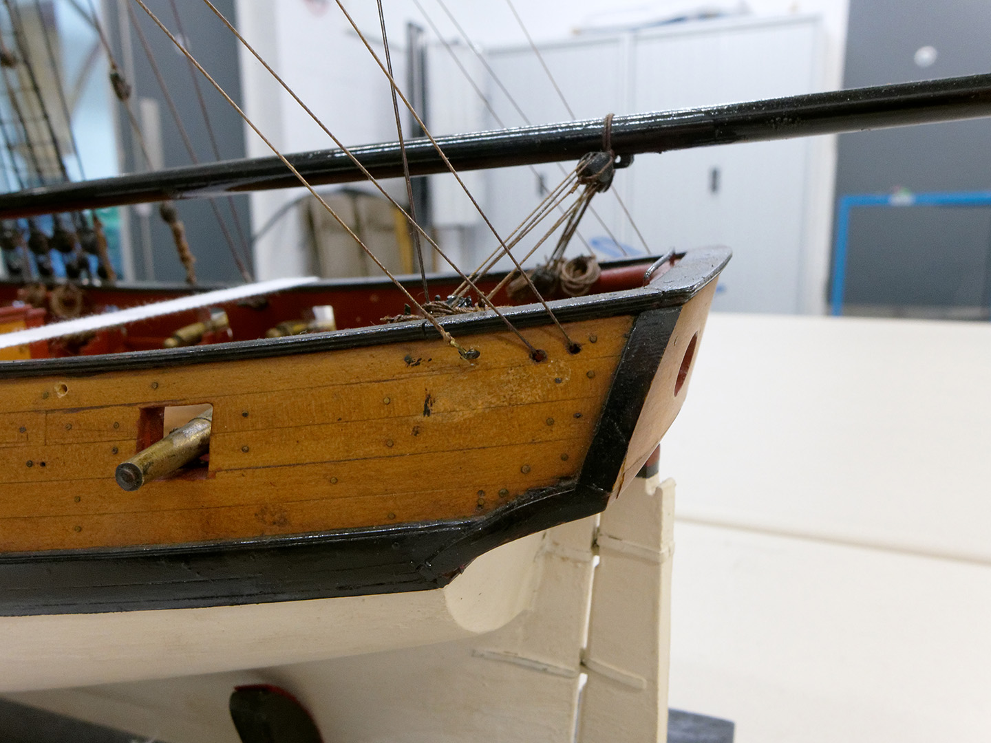
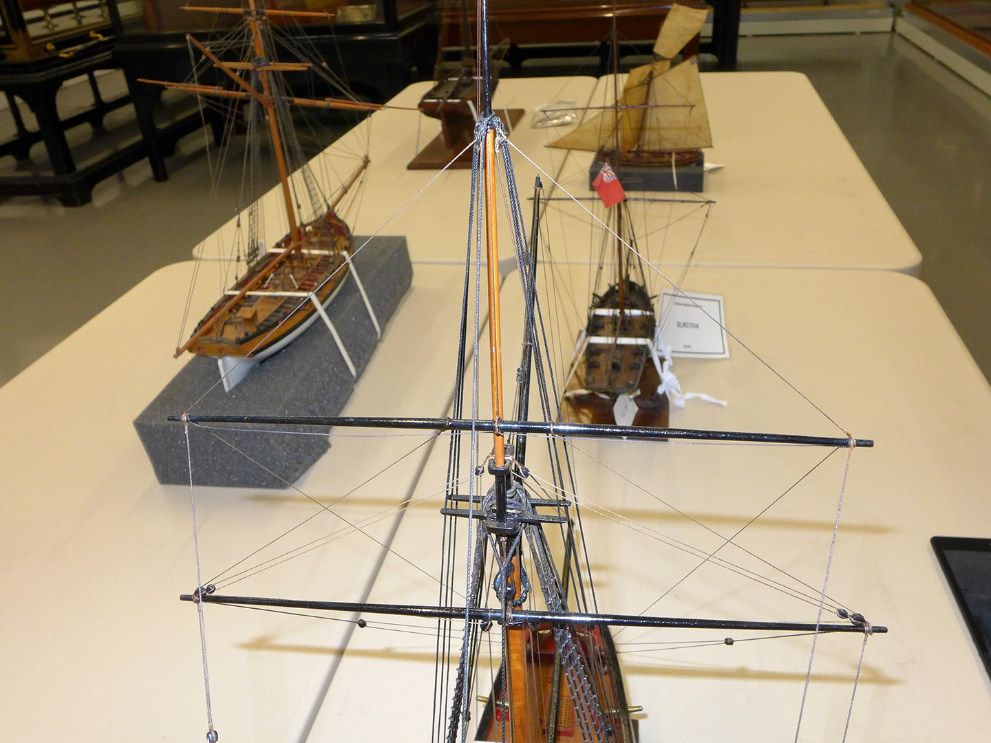
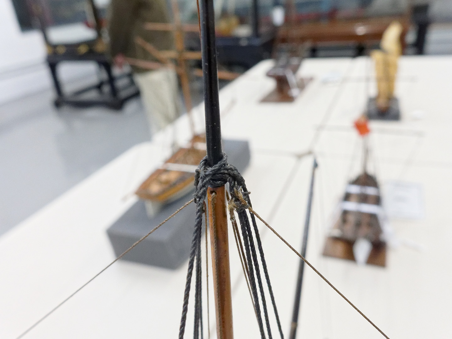
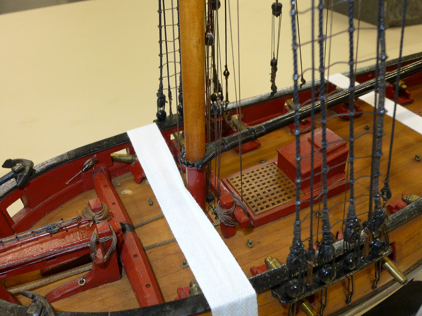
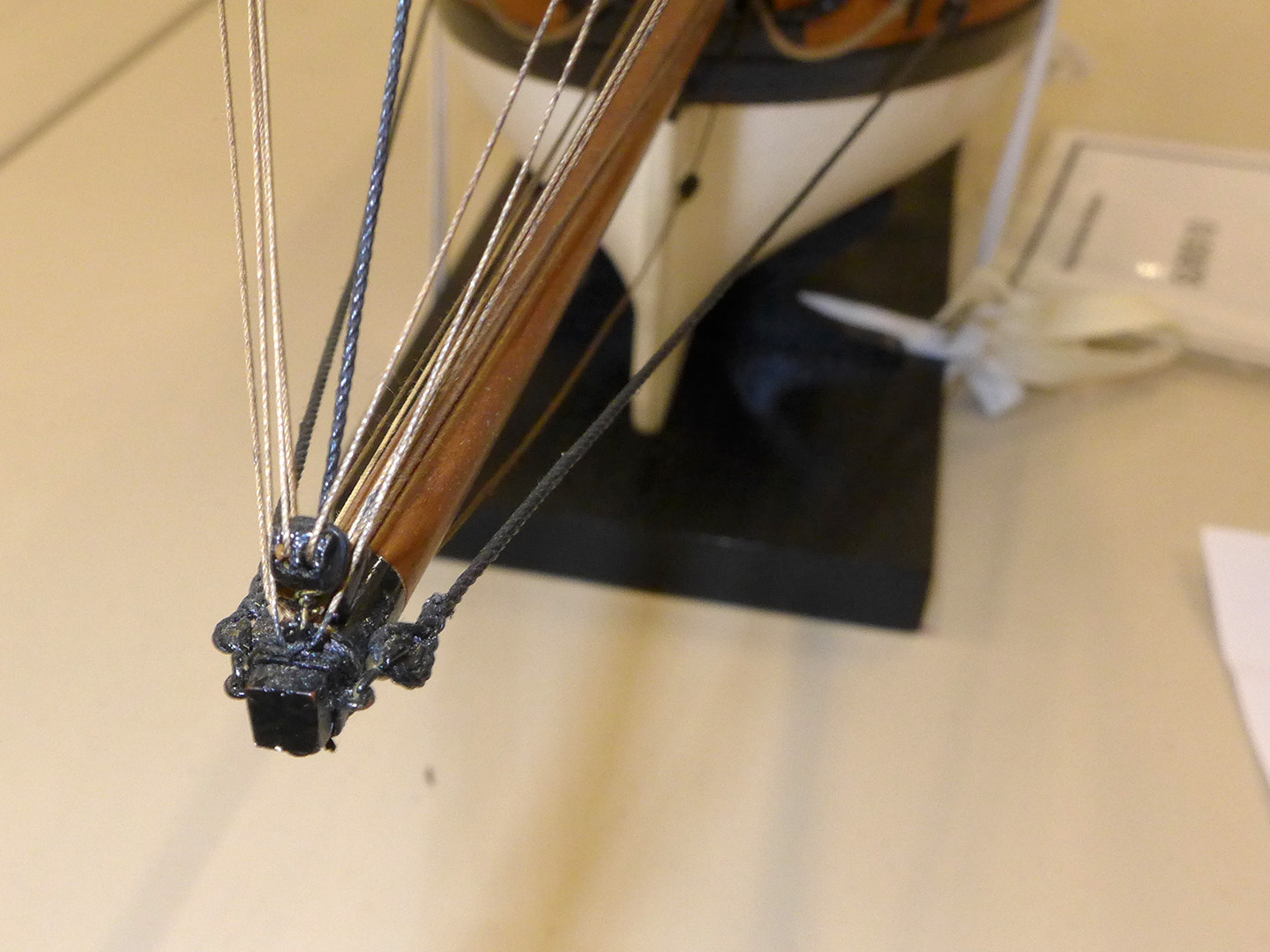
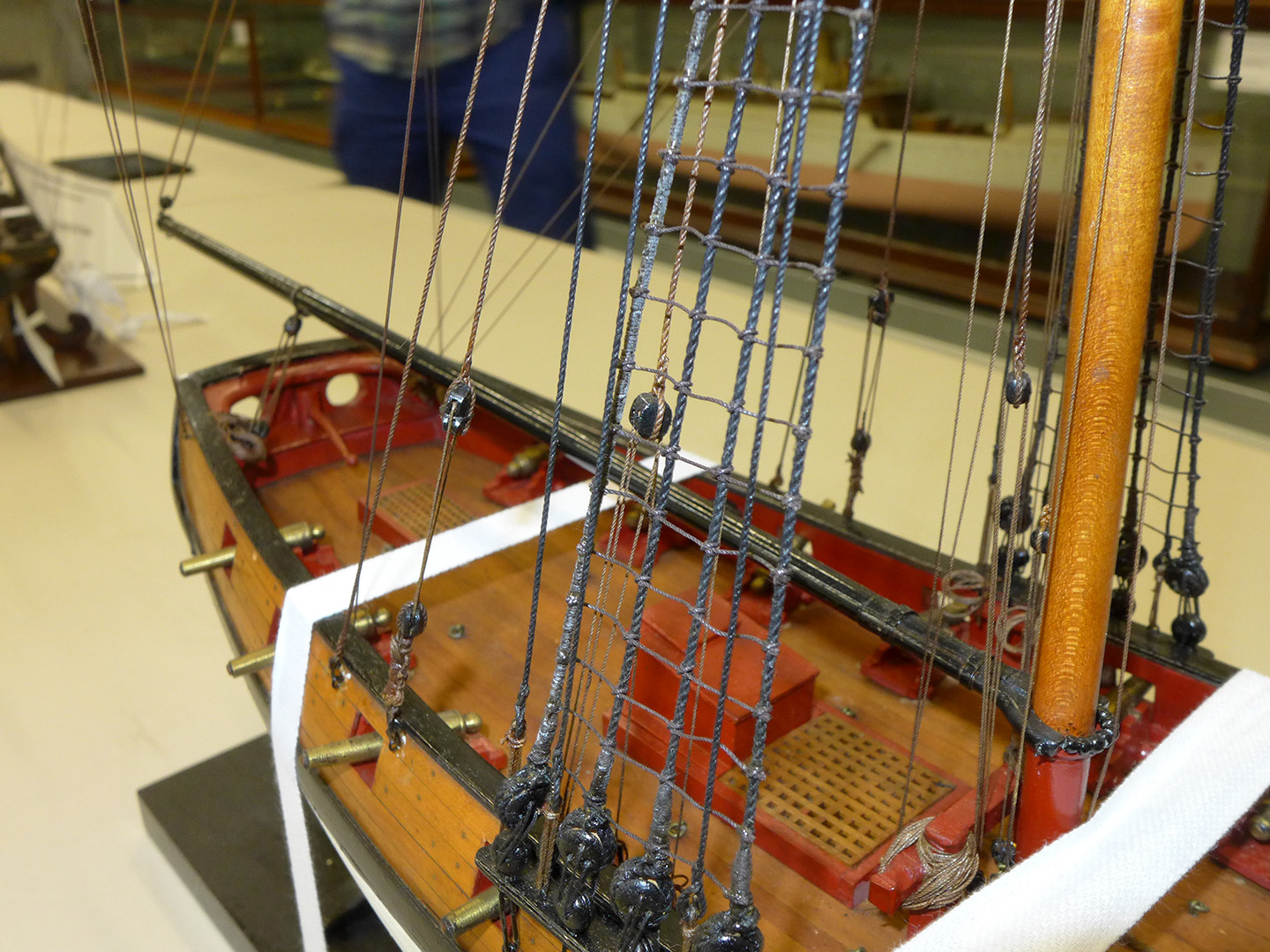
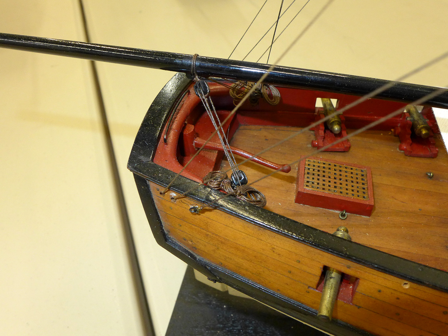
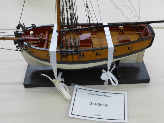
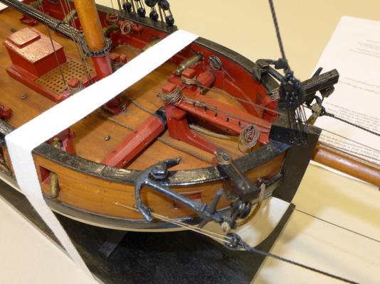
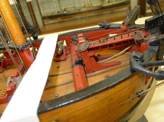
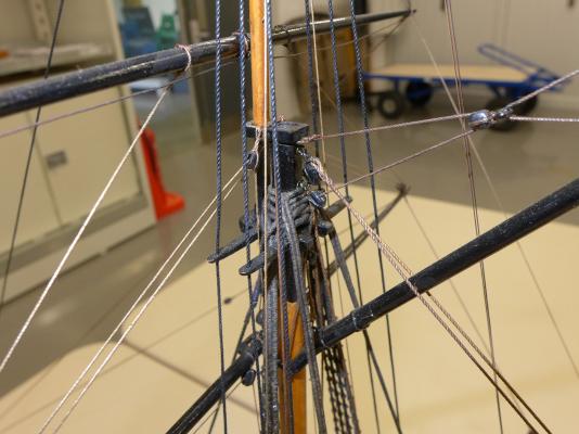
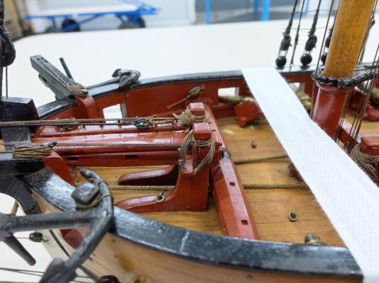
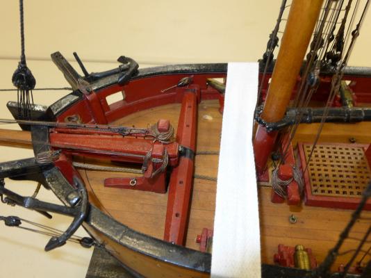
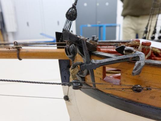
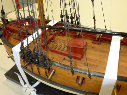
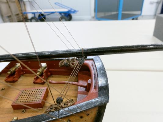
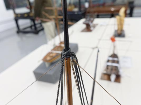
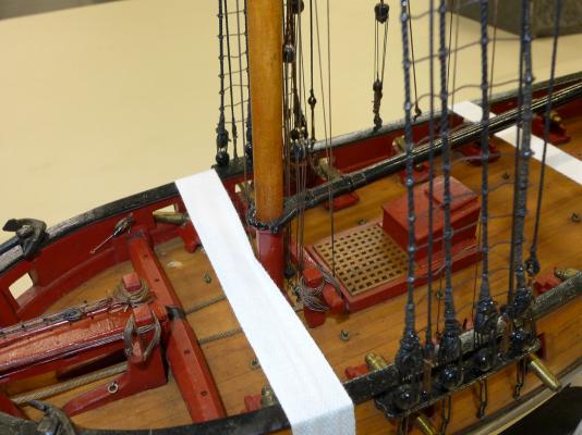
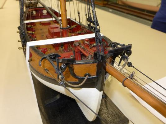
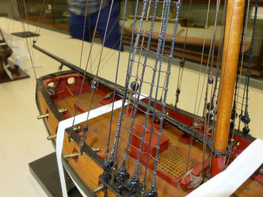
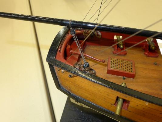
In order for me to understand better the rigging practices for cutters of the 18th Century, I wrote to the National Maritime Museum asking if I could see some of the cutter models they have in storage, now that they no longer have a model display at the Museum in Greenwich. Nick Ball, the Assistant Curator of Ship Models, wrote back very quickly saying that I would be welcome to visit and could see all of the models I had requested which are now stored at the Royal Historic Dockyard in Chatham -- except for one which was stored in another location less accessible to the occasional visitor. He, together with Dave Lindridge the Store Manager, gave me a very generous amount of time to look at and photograph the models that they had taken out for inspection – during which they provided a lively discussion about their jobs and the models they were showing. In fact Nick said he was pleased to show visitors the models because it gave him more of an opportunity to review models in their vast collection. I asked Nick about permission to post my pictures and he told me it was fine as long as I made it clear the pictures were from the NMM collection. He also asked to be provided to the links of the photos as he himself (as a trained naval archaeologist) was very keen on the details and would enjoy any discussion that ensued. I will post the photos of the individual models under different messages, this post deals only with the first of the models. I just need to add that I am enormously grateful to Nick and Dave for their patience and generosity with their time for this visit, which for me was invaluable. 1763 cutter NMM ID SLR0510 First off is their cutter referenced in the NMM as Object ID SLR0510. It is described there as “a full hull model of a cutter (circa 1763) Scale: 1:48. The vessel measures 53 feet on the main deck by 20 feet in the beam and is armed with twelve 3-pounders. The model was donated unfinished and was completed in the Museum in 1960”. For me there were four main points of interest, apart from the fact that it is dated the same year as my Sherbourne. The first is that the fore belaying pins are arranged fore-aft beside the bowsprit. Gregor, Dirk, Kester and I have been trying to figure out how the belaying pins would be set given that the kit of the Sherbourne provides no plans for such a belaying rack. Each of us have provided our own particular possibility – with Dirk going for an arrangement such as that on the AOTS book of the Alert, and Gregor going for a rack right on the stem. I had made a rack that was parallel to the windlass. However, now I have seen the arrangement on the NMM cutter SLR0510, and, as you will see, the 12-gun cutter I saw had the same arrangement, I have changed my own rack accordingly. The second is that the topmast is fore of the main mast. I had understood that earlier in the century the practice was to place the topmast aft of the main mast. In fact the cutter Hawke (which I also saw at Chatham and whose pictures follow in a subsequent post) was the only one of these models to place the topmast aft of the main mast. The third point of interest was the windlass. The original NMM plans for the Sherbourne showed this type of windlass, and Gregor has already made one in the same style, and I followed his example – rather than following the type of windlass provided for in the Sherbourne kit. The fourth point of interest is that, like the Trial that you'll see in a subsequent post, the lower hull is painted up to the wales, and not to a waterline. The following were the other pictures I took of the1763 cutter, all of which will have details which will be picked up by those more knowledgeable than I am! Tony


- 42 replies
-
- 22
-

-
- Cutter
- 18th Century
- (and 4 more)
-
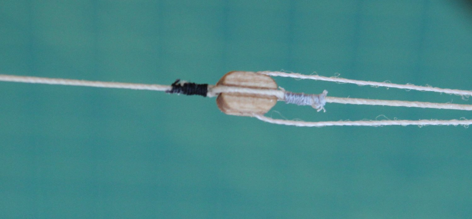
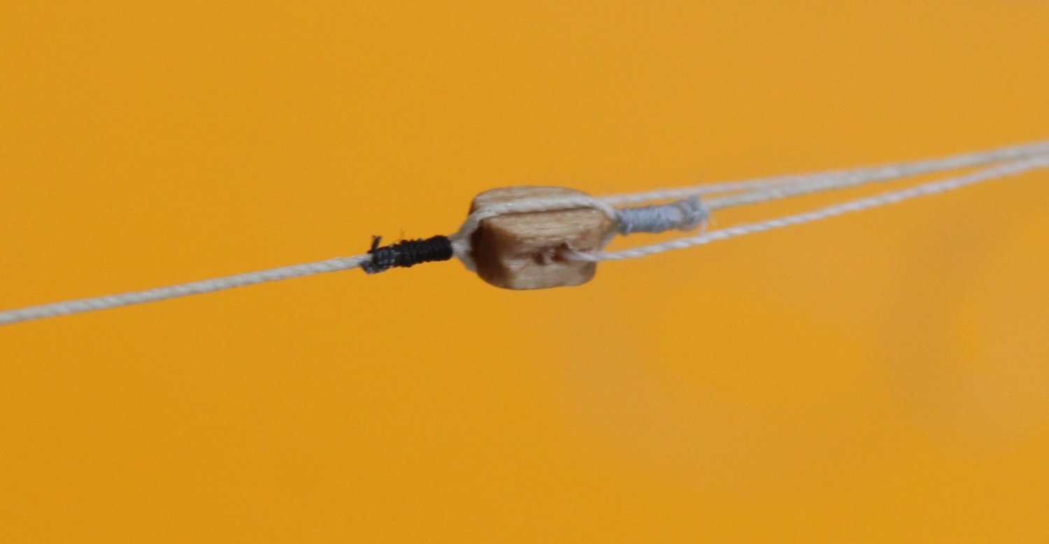
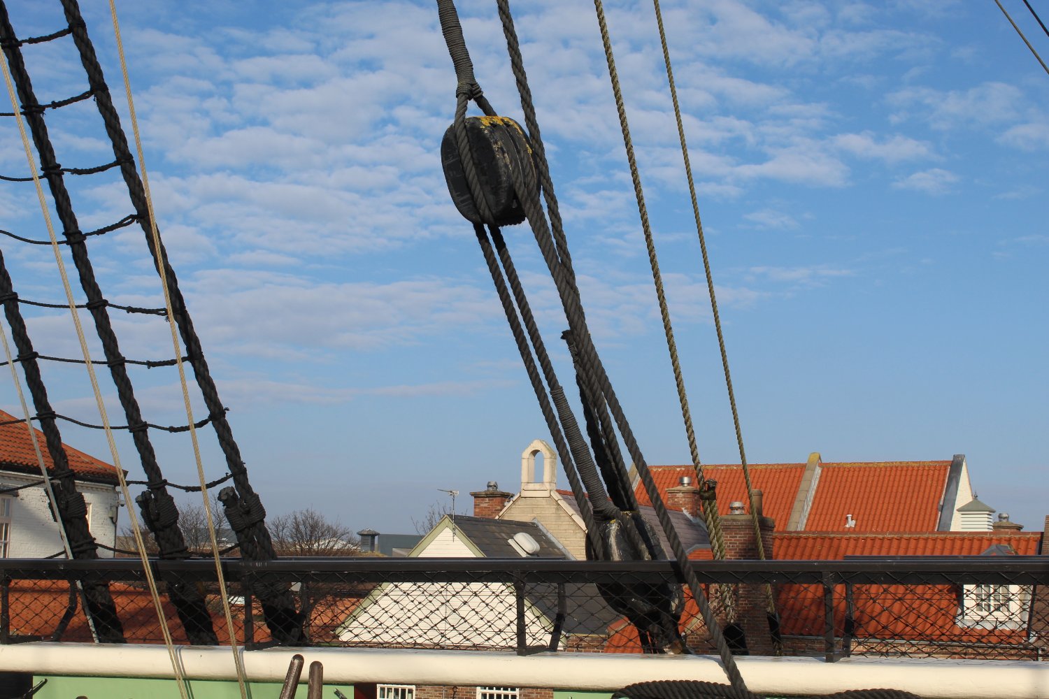
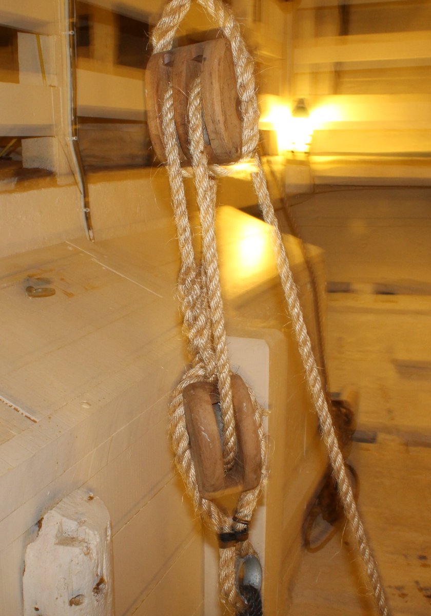
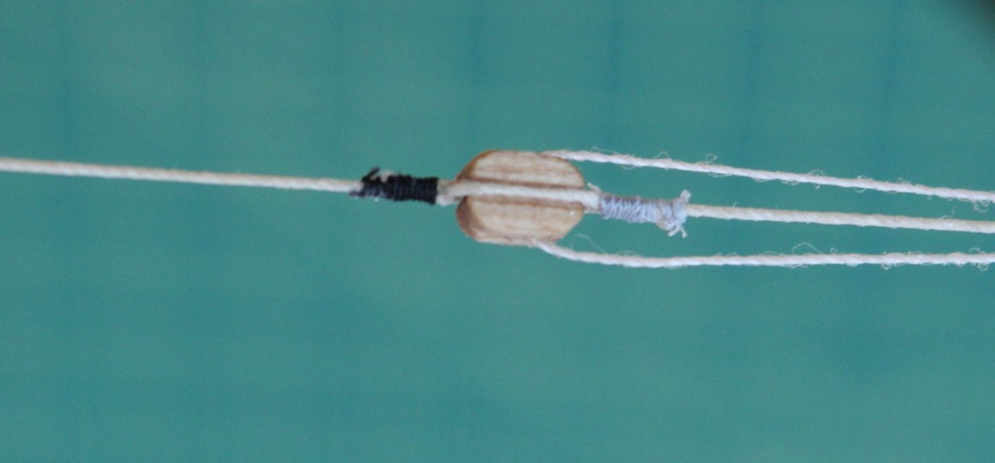
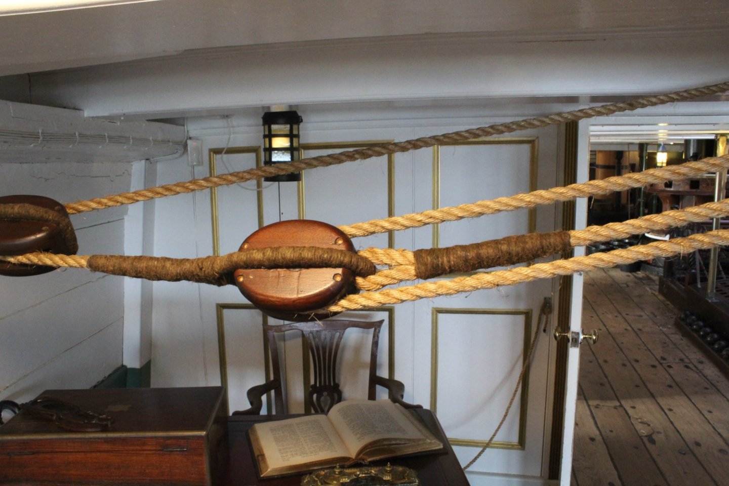
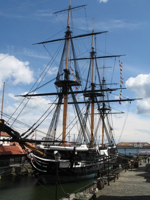
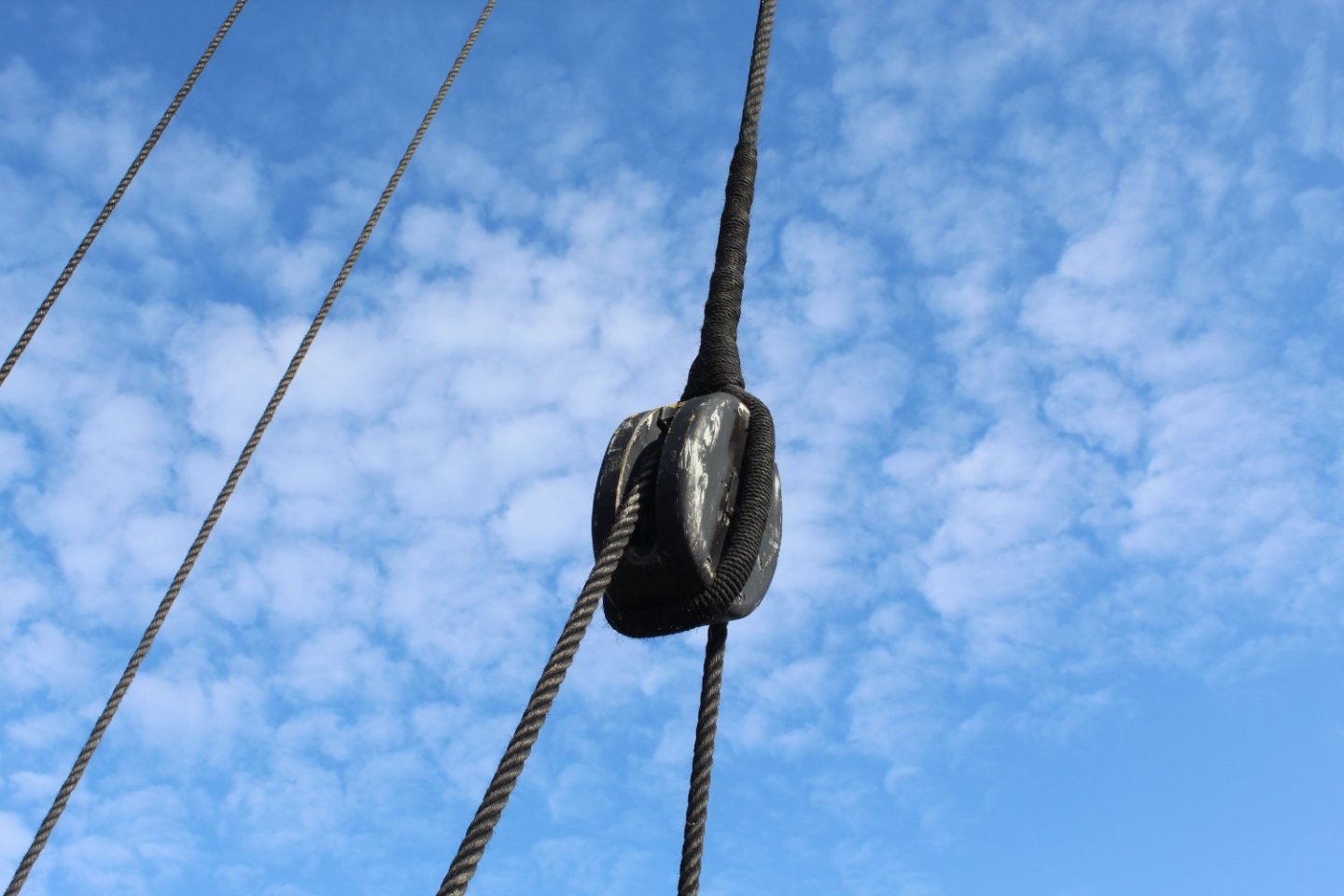
I visited The National Museum of the Royal Navy Hartlepool to have a look around HMS Trincomalee which is a Royal Navy Leda Class sailing frigate built shortly before the end of the Napoleonic wars. It is well worth a visit. Part of the reason for the visit was to look at the rigging to see if I could improve my methods in readiness for my next project which will be the HMS Indefatigable. I am fully aware that the Indy is a different class of ship to the Trincomalee. Also the Trincomalee, being a museum exhibit, has undergone a lot of restoration work. . I took plenty of photo's of various aspects of the rigging (and belaying) and it quickly became apparent that there were plenty of things I could do which would yield better results. With that in mind, and knowing it will be a couple of weeks before the Indy kit is released, I thought I would experiment to see what I could do better. When looking at the following photo I noted that the rope used to seize around the block had been served. I also noted that just have much more the rope was seized compared with what I would normally do. I decided that using a served rope around a block was not something I was going to replicate. I did however try extend the amount of thread seized and I also ensured the seizing extended past the cut ends of the thread. In the two pictures below I used 0.25mm natural thread which was seized using unwaxed Semperfli Spyder thread. I used grey spyder thread at one end and black spyder thread at the other. I think the grey looks better with the natural thread. I am going to order and try some differ spyder thread colours as there is a nice looking brown spyder thread which I think will be a mch better option. In the following two photos the seizing consisted of alternate half hitch knots 16 on the bottom and 16 on the top. I probably could have added a few more to extend the seizing even further which is something I will experiment with over the next couple of weeks. I have also attached some more photos of blocks which I will try to replicate over the next few days. In the next photo the bottom block required a thimble adding to the bottom of the block. In this photo the bottom block is secured to the hull via an eyebolt arrangement,


-
 I want to buy assorted items for my current build (1:80) but I still can't figure out how to measure my dead eyes and blocks (and cannon and wheel and bell and lifeboat, etc) Do i measure the long side or the short? thickness or length might be a better way to say it for the blocks. do i measure across the circle for the dead eye?
- 4 replies
-
- 2
-
-
- measurments
- dead eye
- (and 3 more)
-
Hello everyone. I am currently building Model Expo's Fair American and am rather disappointed with the plans. They don't show any detail about the running rigging, particularly the bowsprit, Does anyone have suggestions on books, pics or other resources to consult?
-
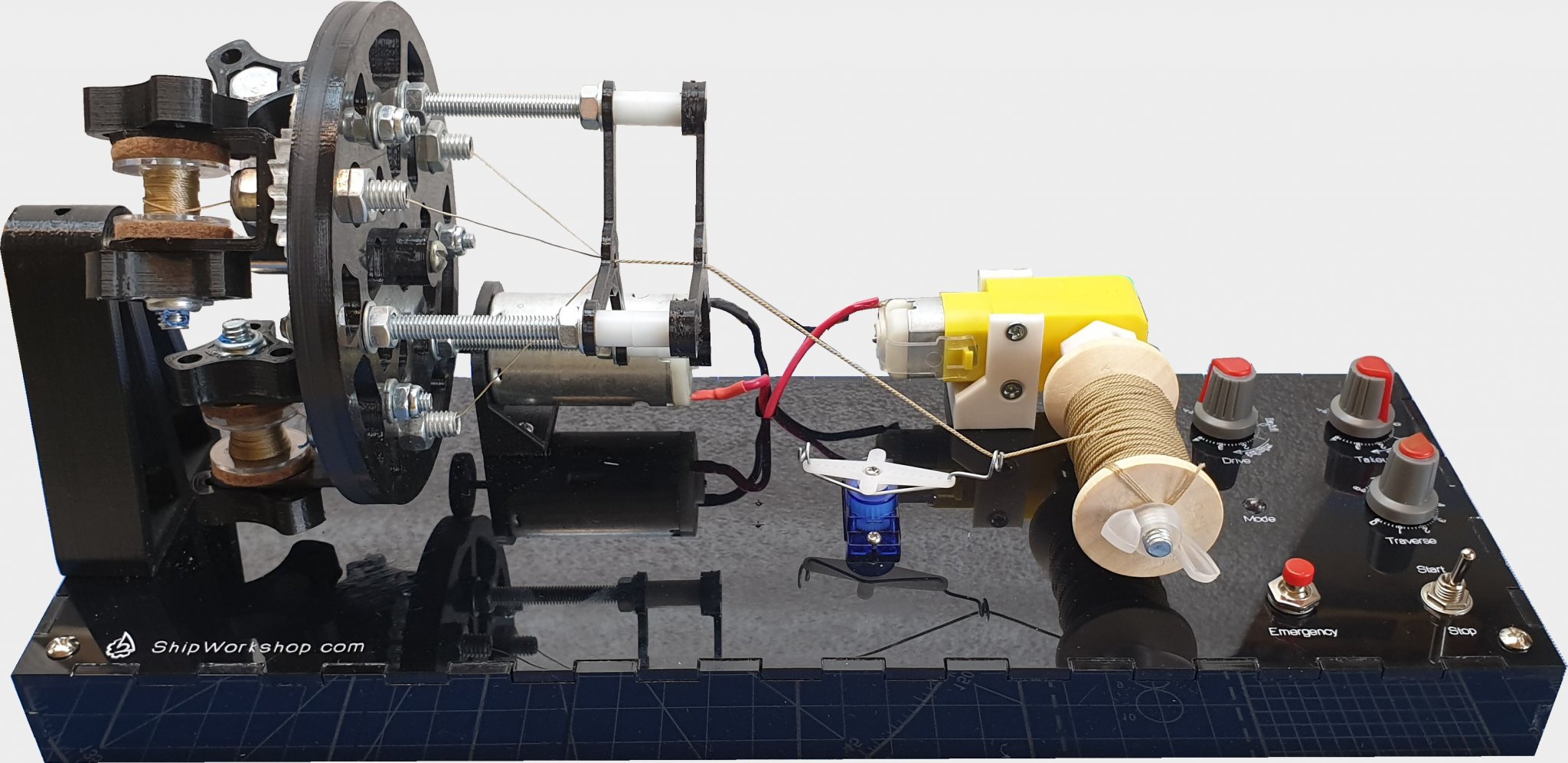
 Dear friends, I proud to let you know that we are completely renewed and run new version of our site - ShipWorkshop.com Whats new: Redesigned "Shop" with credit/debit card processing as well as payments via PayPal; Our "News" implemented as blog where we can communicate with our customers showing them product design changes as well as just put some useful info in; Redesigned "Downloads" section where you may find printed/video guides how to assemble and use our tools. We still provide some services for modelers like: Complete ship reconstruction, Design the hull, Model construction and custom tools design for your need. You may "Contact" us filling the form or just drop us email.
 -
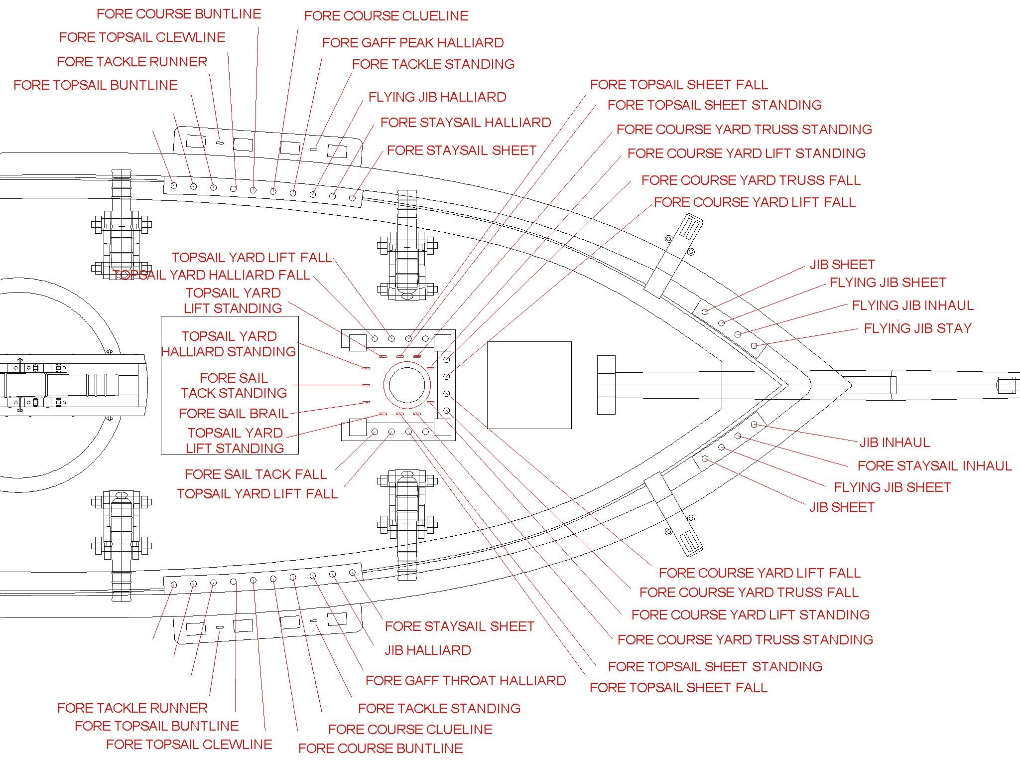
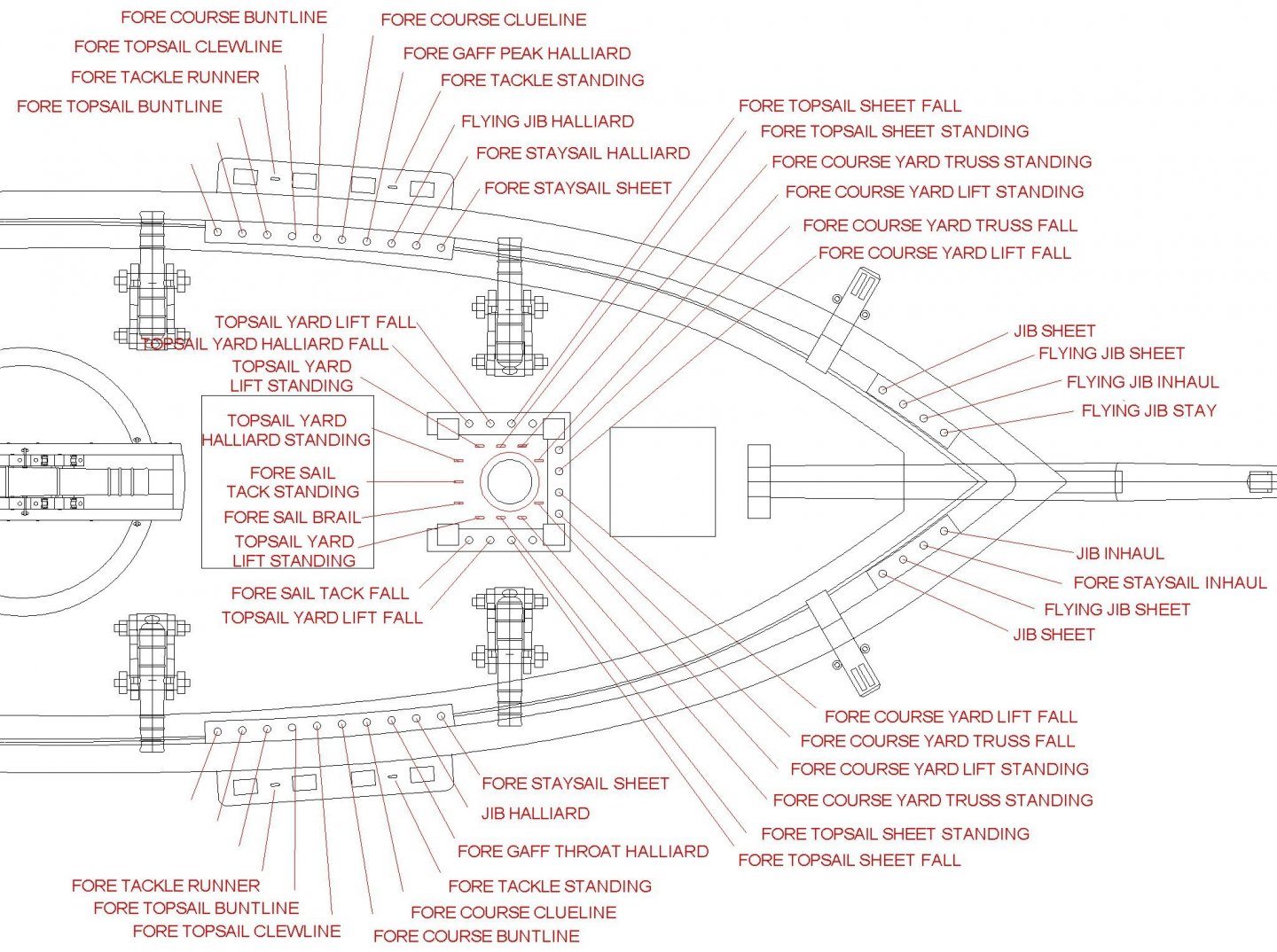
I am building the Mantua Albatros Art 771 kit from the 1980s. I am trying to create a belaying plan for the ship. The main mast is simple, but the fore mast is quite complex. The Mantua plans show only the basic standing rigging, and show none of the running rigging. I have eleven books that discuss sailing ship rigging, including the standards Steel, Lees, Biddlecombe, Lever, etc., but these describe full square-rigged ships and are mostly useless for deriving a schooner rigging and belaying plan. After detailed discussions of how to rig the lines on the masts, spars and sails they all finish by saying the line "runs to the deck." I do have several books that talk specifically about schooner rigging (Petersson, Underhill, Leather, Hahn, Marquardt). Most of these also say to run the line "to the deck" or "to the rail." Again, no help. Petersson's "Rigging Period Fore-and-Aft Craft" shows the belaying plan for a topsail schooner, and is the best reference I have found, but it doesn't describe the variations found on different ships. Underhill's "Masting and Rigging the Clipper Ship and Ocean Carrier" has far and away the best an most detailed discussion of ship rigging I have found, but it is mostly for full-rigged ships, with only a brief discussion of schooners. Marquardt's "Global Schooner" has good detail about rigging but it also says the lines run "to the deck." Leather's "The Gaff Rig Handbook" is nearly useless, having no useful index and focusing mainly upon 20th century racing yachts. So I have been left to my own devices to figure out how to belay the fore mast rigging. I am using two assumptions. First, lines coming down from purchases close to or on the mast lead down to ring bolts or fife rails at the base of the mast (or pins, cleats or spider bands on the mast), and lines running from the yard arms run down to the pin rails or cleats on the bulwarks or to ring bolts in the waterways near the bulwarks. Second, lines from lower purchases lead forward, and lines from higher positions lead aft. The idea is to avoid crossing lines. Here is my working plan: As you can see, there are 35 running rigging lines coming down from the foremast (not counting studding sails!). The base of the mast seems a bit crowded with 21 standing and running lines attached to ring bolts in the deck and pins in the fife rail. To achieve this I had to run the fore course bunt lines and clew lines outboard to the pin rails even though they lead from the lower top and the quarters of the fore course yard. I would appreciate comments and corrections from those who understand belaying better than I do. NOTE: I expect that as I start rigging the mast I will to have to reorder some of these positions to eliminate fouled lines.
-
.thumb.jpg.5a33ce11c7bd2c0f448734dd2e7ea95b.jpg) Hi everyone With me getting more and more into this hobby i find myself not liking the ropes that usually come with the kits. Thats why i have been looking into purchasing one of Domanoff's rope walking machines. My only question, if anyone in here already has one, is: do they already sell the strands in those spools, or do we need to rewind them in the same ones that come with the machine? Also if anyone has any photos of how do the finished product look using those machines, i would gladly like to see them! Thank you very much
Hi everyone With me getting more and more into this hobby i find myself not liking the ropes that usually come with the kits. Thats why i have been looking into purchasing one of Domanoff's rope walking machines. My only question, if anyone in here already has one, is: do they already sell the strands in those spools, or do we need to rewind them in the same ones that come with the machine? Also if anyone has any photos of how do the finished product look using those machines, i would gladly like to see them! Thank you very much -
 Dear Fellows, I have difficulty to interpret the "fish hook-number" written by hand in many numbers of the inventory attached. I 'd appreciate your help to proceed my build of the af Chapman cutter. best regards cotrecerf
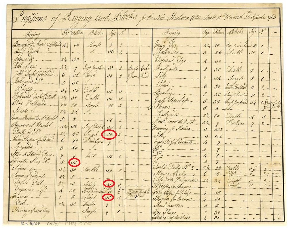
-
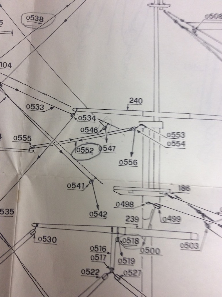
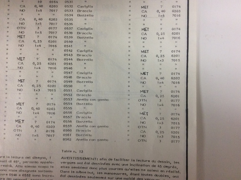
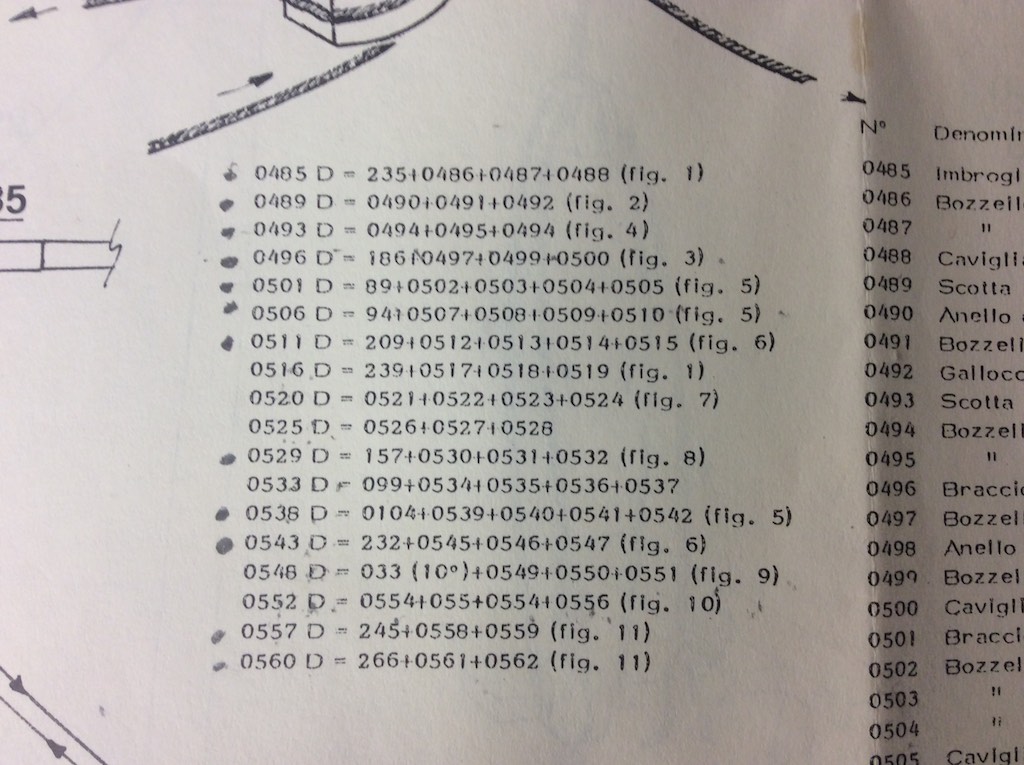
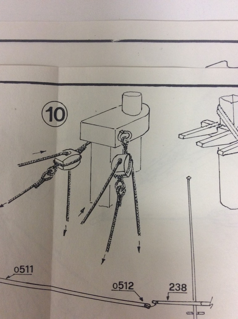
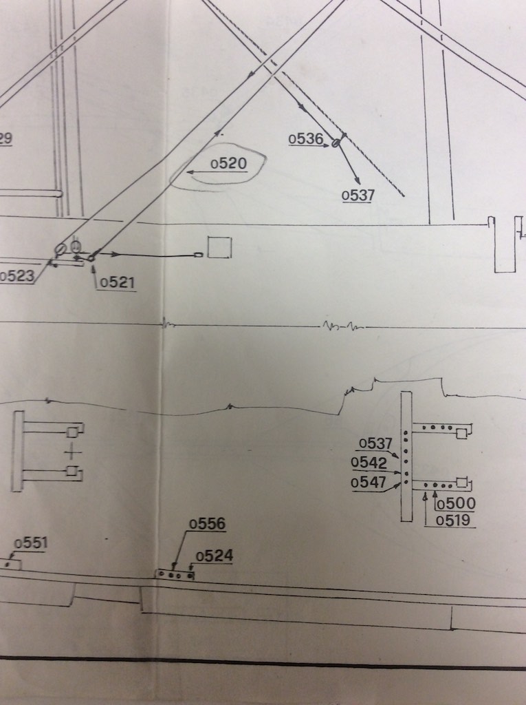
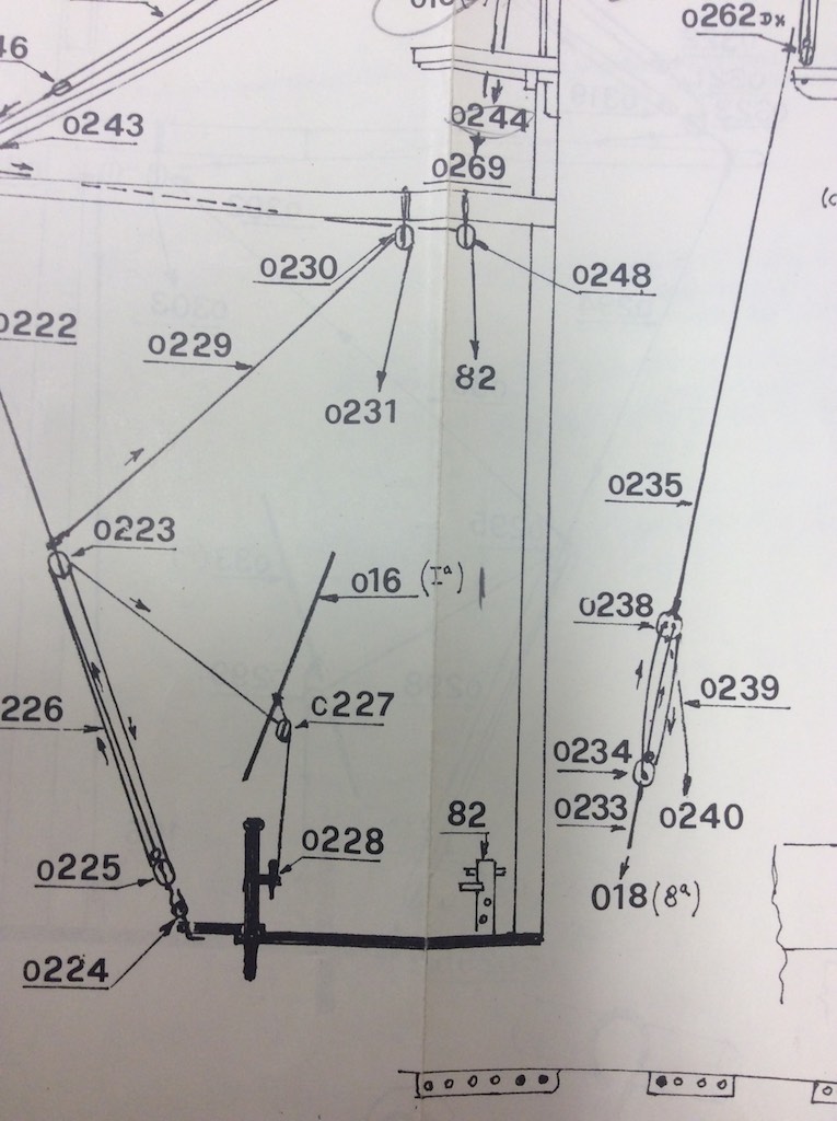
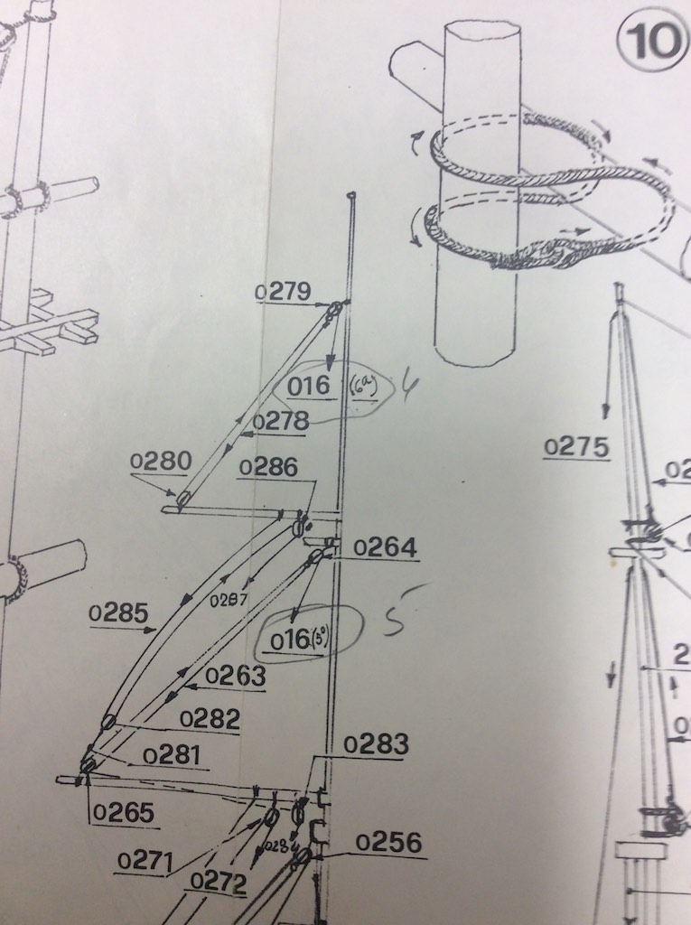
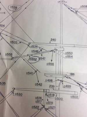
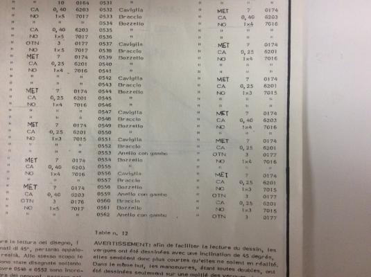
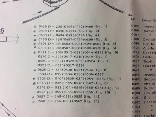
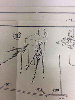
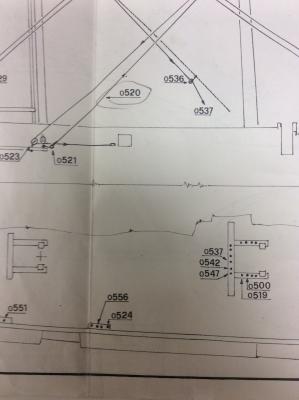
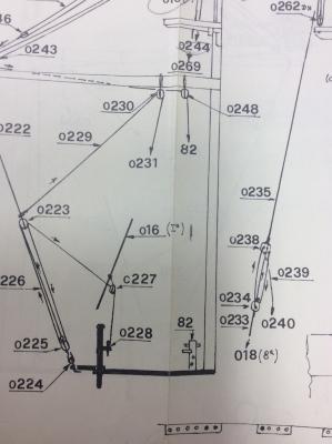
I spent quite a bit of time learning how to read the Mamoli rigging plans. Since there were no explicit instructions on how to interpret the drawings I spent a great deal of time looking through them before I figured out their method. Once I did, it was pretty straight forward. I thought perhaps others might find this useful. Perhaps this is how all rigging plans are done. Since the Connie is my first kit, I have no reference. I also need to mention this kit was purchased in 1991 so it may have changed. However for what it is worth here is how my plans are interpretted. There are two tables on each rigging page. The first table is on the right and lists all the parts, this is standard on all the Mamoli pages. However the second table, placed directly to the left of the first left is only on the rigging pages. the tables are not really labeled or numbered but they are consistent on how they arrange them. The only difference is where they are placed on the plan. For this illustration I will show how to interpret the rigging on the Mizzen (part o552) circled on the drawing. Here is a copy of the appropriate section from the plans: This shows a rigging set running from the tip of one of the Mizzen booms to the cap just above the Main Mast's fighting top. First we need to see what the parts are for this rigging. The size of the line, the size of the blocks, etc. For this we turn to the right most table on the plans. This table is on all of the plans an lists the all the parts of the ship as well as the various sizes. In some cases, the part number might refer to a different page of the plans if the part was installed much earlier so you might have to refer back to another page of drawings. Here is a copy of the section in the table dealing with the rigging for this piece. We can see here that 0552 (o552 in the above drawing) is labeled Braccio (which means "Arm"), the second column tell us that the amount is the same as the above parts, which is 2, although you can't see that in this photo. More importantly, the second column from the right says 0,25, which means this is the 0.25mm line. So now we know the size of the line, let's see where it runs. The second table directly to the left of the parts list table contains the order a line runs by listing the part numbers in the order they go starting at the lines termination in the rigging and ending at the termination on the deck. The entry for 0552 shows 0552 D = 0554+055+0554+0556 (fig 10). This is chock full of valuable information. Ignore the pencil marks, that is how I track when I install a line. First the line will start at at part 0554. We can look on the first chart and see 0554 is a block (Bozello) that is made of walnut and is a single 4mm block (1x4). This also refers to a figure (fig. 10) for more information. This figure is shown below: This shows the manner the blocks are attached to the mast cap. If we want more information on the rings we can refer back to the first drawing of the rigging and see this part is 0553. Referring back to the first table we can see that part 0553 is a 3mm brass eye ring (Anello con Gambo = Ring with shank) the OTN refers to a table in the general instructions that shows it is made of brass. So after the two rings are installed on the cap, the block is added with the .25mm line attached to it. This then runs to the block 0555. The table tells us this is also a 1x4 walnut block that is attached to the end of the spar. The line then returns to 0554 and runs toward the deck. As a note here, if the line also went through the fighting top, that too would have been listed in the order the line ran through it. In this case it does not but goes directly from the block (0554) to part 0556, which table 1 informs us is a belaying pin (Caviglia). The termination point is shown not only in the table but also in the rigging diagram. The sheet also has a diagram showing the layout of the termination points when viewed from the rigging. From this we can see that 0556 is the third belaying pin aft in the 4 pin belaying rack located on the starboard side between the two fife rails. The port side has a matching set for the matching mirrored rigging set. So that is it. A further note on terminations, if a line terminates tied to a side shroud, the shroud grouping is noted and it is numbered from front to back. So the rigging drawing would show the shroud set from the side and give you the number it would be referred to as. This would look like the following: Any lines terminating on one of these shrouds will be labeled 16(x) with x being the number of the shroud from the bow. The following drawing shows how this shroud is referred to int he rigging drawing. So this shows the top line would terminate on shroud set 16 on the 6th shroud. The one below is marked to terminate on the 5th shroud. It is hard to read but you can see my pencil marks to the left of the number. So this is how the rigging plans work. I stopped working the lines from the top of the table down since they tended to number the lines from the bottom up. This meant that the top lines which normally run down the center of the ship, had to be fished through the other lines. However, other than that, I have ben following these diagrams pretty much as they are drawn. [ dia=core:attachments:202725]

-
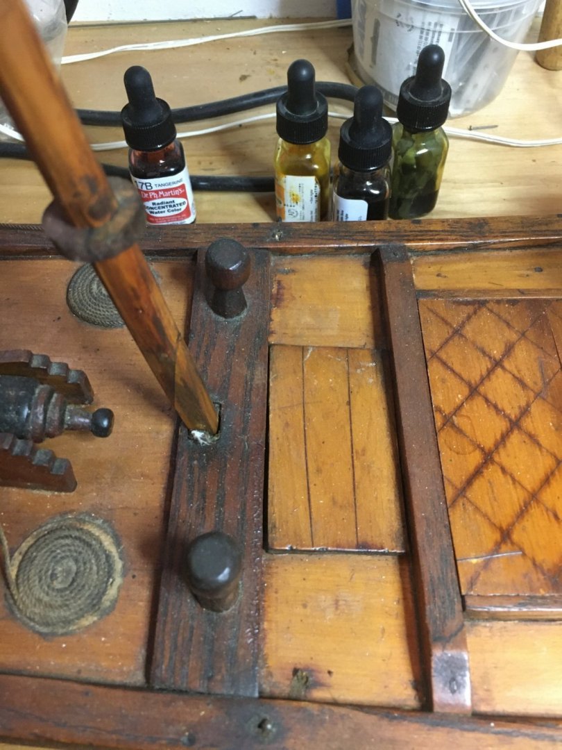
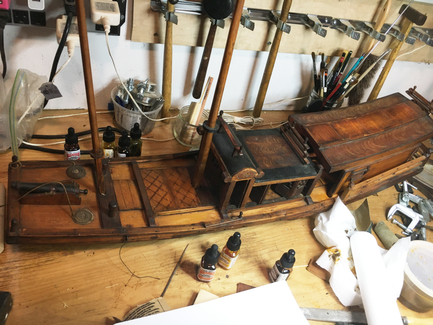
I am new to MSW but involved with model ships professionally for years. I was a curator of model ships at a major maritime museum and appraised them for both Sotheby's and Christies. I have a 100 year old Yangtze River gunboat junk of the type that was made for the tourist trade in the 1930's. I am trying to figure out where the foresail rigging lands on the deck as there are no indications of holes for eyes. There are two capstans astride the mast, and the partners on either side of the mast have part on top that protrudes and has no discernable function aside from a place to secure lines. As a side note, I have a quantity of very fine French linen thread and I wonder what they are worth.
-
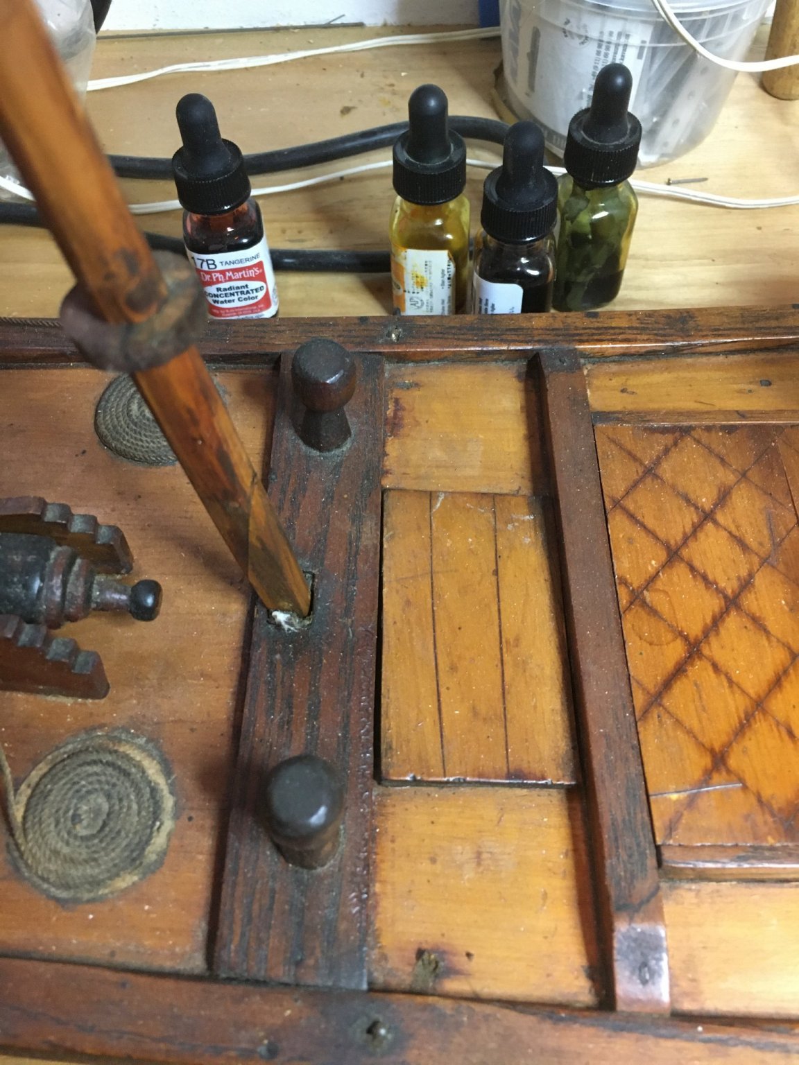
 I find myself continually bumping up against my ignorance. I feel pretty good about getting my masts assembled to be straight. Now I'm adding the various blocks that will be part of the running rigging. There are a number of blocks - see picture below - that are attached to the one mast or the other between the cross trees and the cap. I cannot make out what knot to use to properly attach those blocks to the mast. Can I please get some advise on how to rig these blocks in an authentic way? Thanks, Rich Klecker
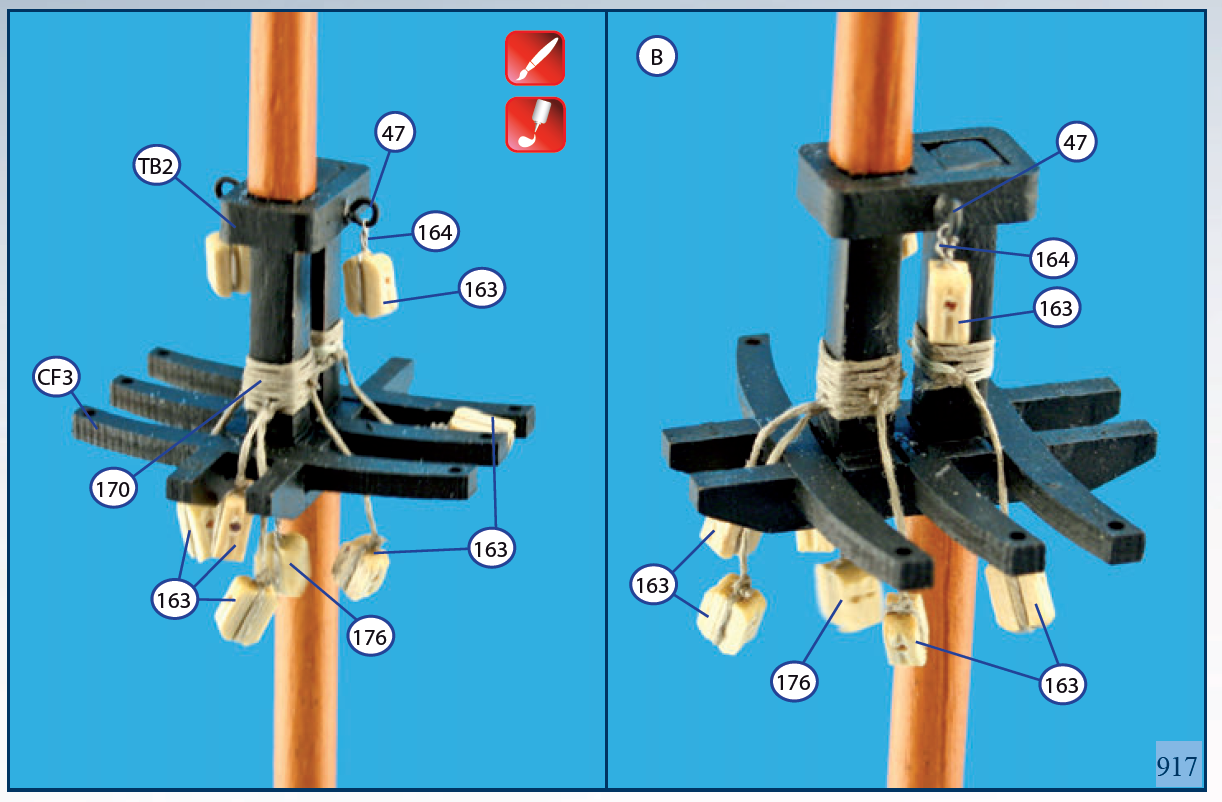
-
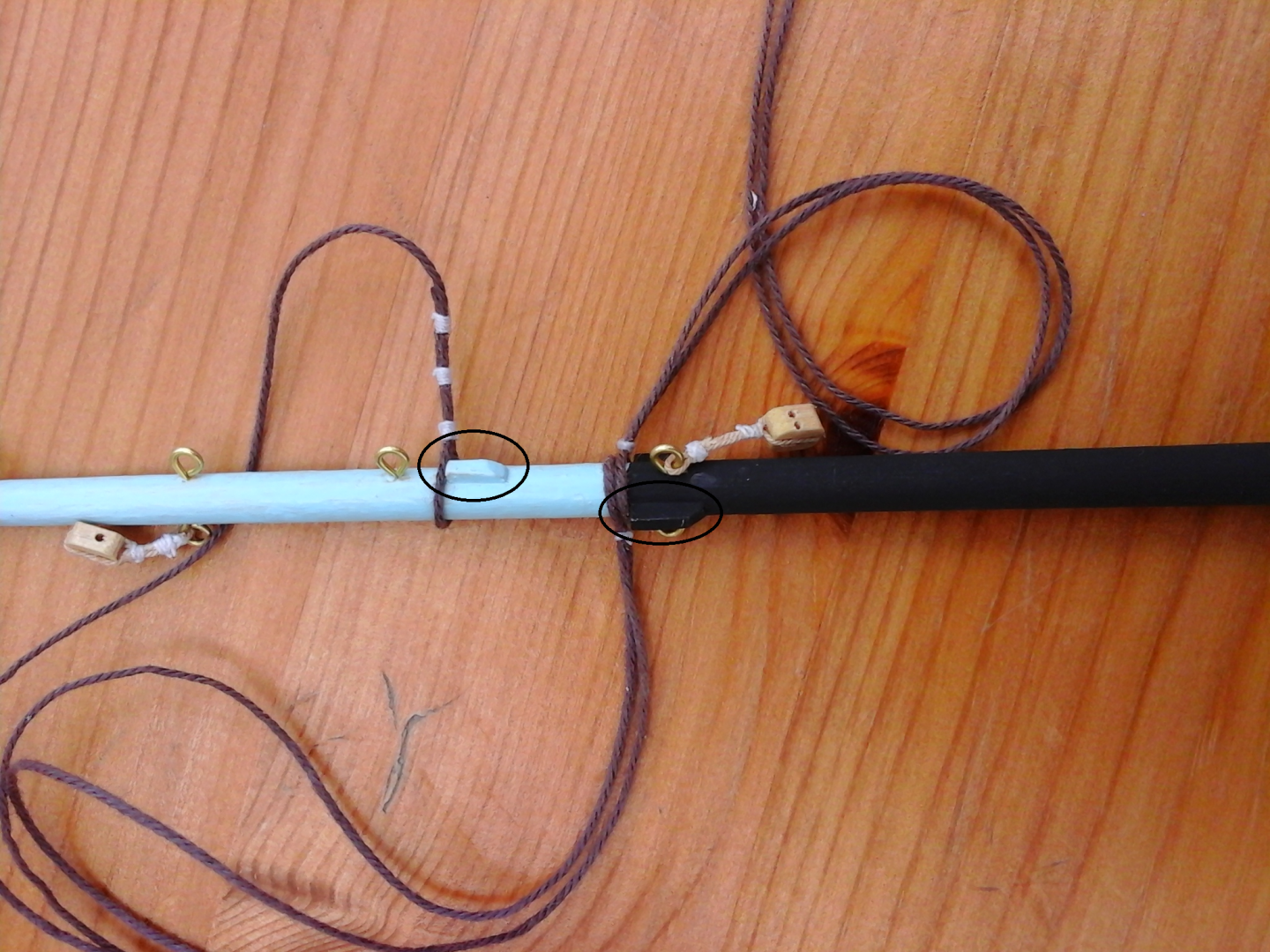
Hi everyone! Im new to ship modeling and i recently started my first ship, the AL Bon Retour. I have looked a lot of information up in this forum (you guys are amazing) and in others. Im hoping, once the ship is done, to upload the final producto for you guys to see. Im at the point where the hull has been planked and painted over, and im moving to rigging. This has proven to be very challenging, since AL kits dont usually come with a lot of pictures, and understanding the diagrams for a novice like me is taking me some time. I have a question. There are some "blocks" on the mast of this boat which lines loop around and apply tension to. I will attach a picture so you will know whatim talking about. My question is how do i do them. I know i need to "file" the mast to the appropiate width. Do i work around filing? Do i just prepare a piece of wood and glue it with PVA? I need some advice. And sorry for bad english
-
Hi. I'm trying to date a historical map, and it has been suggested that someone on this forum might recognise particular features of ships drawn on the margin (see below) which might pin the dating down to a particular decade of the 18th century. The map itself (of part of the south coast of England) is very sketchy, and what seems to be an even sketchier copy of it in the same archive collection has accounts scribbled on the back dated 1750. I'd be interested to know the likely occupation of the depicted ships too. Thanks in advance for any helpful suggestions! Stephen (on Twitter @docuracy)
- 17 replies
-
- 2
-
-
- flag
- 18th century
- (and 3 more)
-
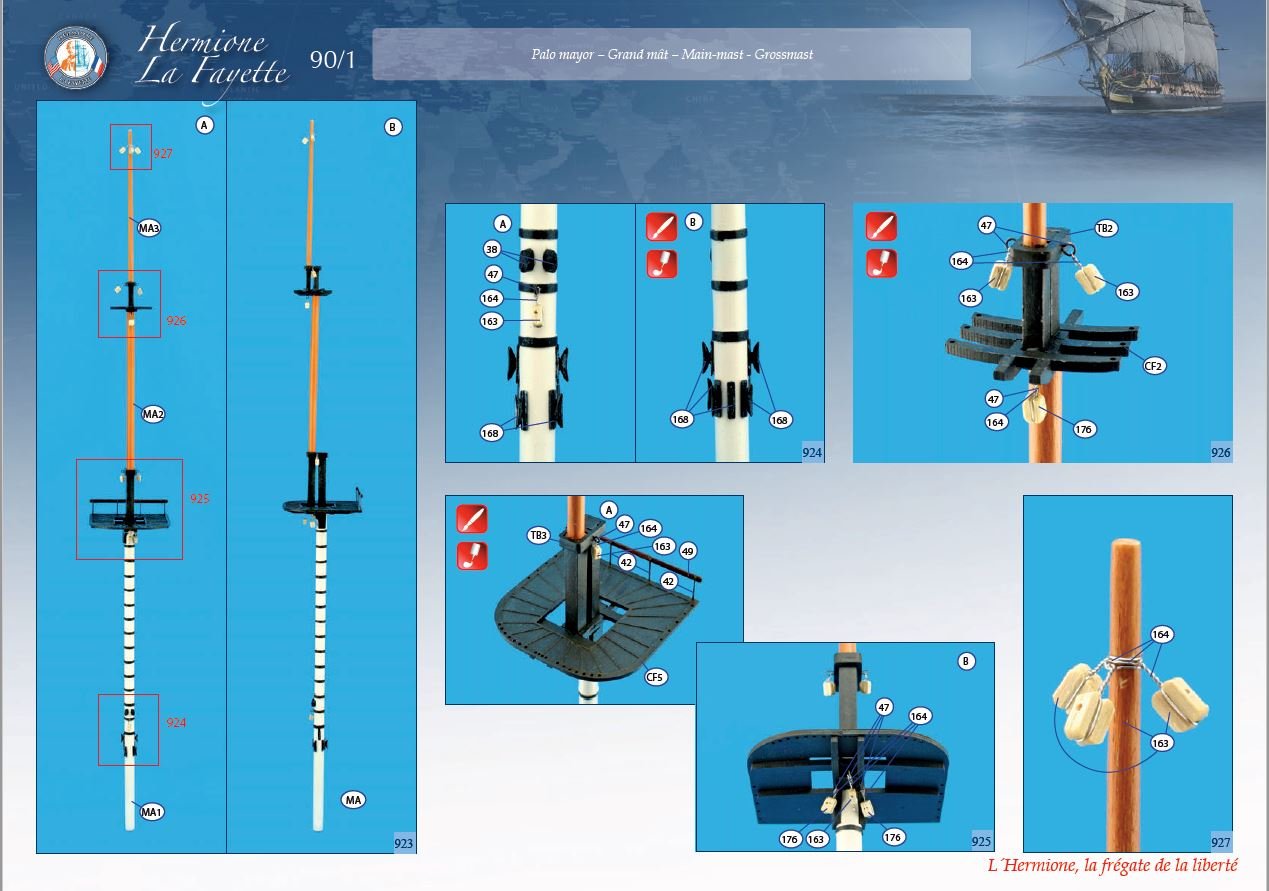
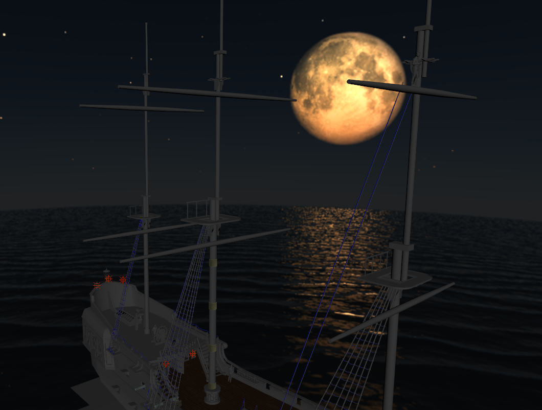
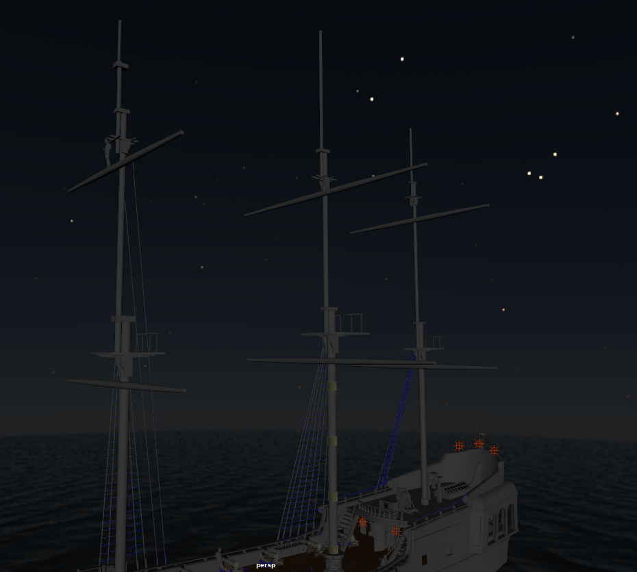
After many months I am now at the point of putting masts on the model and I can't make myself get started. I'm building AL's L'Hermione. I have cut and tapered the masts, they're painted and some of the blocks are installed. The AL instructions for this portion of the build are very abbreviated - read just pictures, no descriptions at all. The picture show the details for the individual masts and then it shows the masts assembled and ready to be placed into the hull. As I think about how I would assemble an entire mast I begin to wonder how that mast can be built to be straight and the individual masts properly aligned with each other. I've searched through the many contributions on this and related topics. It seems like there is a strong preference by many to install individual masts, attach the relevant standing rigging and then move up the mast; mast, then top mast, then topgallant mast. My concern with this approach is that as you work up the mast assembly you start working "in the air" with fewer and fewer reference points regarding alignment and plumb. Can I please get some help or guidance about how to proceed here. I need a push. Thanks
-
This post is intended for anyone who has built, is building, or is contemplating building HMS Victory, whether in kit form or scratch built. Others with an interest in Rigging generally may also like to chime in. I've come across an interesting conundrum regarding the rigging of Victory that other Victory builders may be interested in. I spent several hours poring over documentation to try and work out the use of Yard Tackle Pendants and Brace Block Pendants. I consulted several sources, but my primary reference for any assertions here is Longridge. I also sent a PM to Gil Middleton to seek advice on his approach to this aspect - his reply is posted within Gil's own log (as we had a problem with the PM system), so I won't repeat it verbatim here. First up, as far as I can tell, Yard Tackle Pendants are only used on the lower yards of the Main and Fore Masts. Longridge talks of these in the text descriptions for each of the yards, and this is matched by the drawing of the Running Rigging by Campbell (Plan No. 7 in Longridge). Secondly, I don't believe Pendants were used for Braces except for the Cross Jack Yard. Longridge specifically states (pg 258), in his description of the Cross Jack Yard, that "Here is the only place in the ship where Brace pendants are employed." I also checked over McKay's AOTS book, and as vague as it is, it does seem to match Longridge as well, with the exception that it does not show brace pendants for the Cross Jack Yard. I got terribly confused by all of this as Antscherl (in TFFM) employs brace pendants on all yards, and although he shows the Yard Tackle Pendants, he doesn't say much about them. The Mamoli kit plans, as bad as they are, actually do match Longridge (now there's a turn up for the books!), with the exception of the Cross Jack Yard Brace Pendants, and belaying of the yard tackle pendants. I got further confused when I looked back over Gil's excellent log, where he has employed brace pendants on all of the upper yards. So I asked Gil about his sources and choices. Gil's response was (in essence) that the Jotika plans showed them this way, and that this matches his photographs of the actual ship (see Gil's log for these photos). He opined that Longridge was basing his version on the 1922 restoration and that this may have been different to the more recent restoration to (supposedly) the "Trafalgar" state of the ship. Gil also quite correctly points out that different Captains changed rigs to suit there personal preferences, so unless we can go back and interview Captain Hardy, we might never know for certain. In the meantime, Gil has chosen to stick with the Jotika/Trafalgar restoration version, and I have decided to stick with the Longridge version on the basis that if Longridge is wrong, then I'm happy to be wrong with him. I've also been confused by the belaying of the Fore Lower Yard Tackle Pendants. Longridge, in the text (pg 242), is quite vague saying, "The pendant...is a 7-in rope with its lower end spliced round a 13-in double block which is connected by its 3 1/2-in fall to a 13-in single block which hooks on to an eyebolt in the side of the deck." In the diagram (Plan No.7) "the side of the deck" seems to translate to the Fore Channel, and this matches the drawing in McKay (pg 109), though neither actually show the final belaying point clearly. In checking the text again, Longridge's Belaying Plan (Plan 10, pg 266) and his Table of Belaying Points (pg. 270) both show that it belays to the "7th timber head, side of forecastle". But this raises another question for me - how does the line get to this belaying point without going through the shrouds/ratlines and/or the hammock netting and consequently becoming fouled? It would make more sense to me to belay it on the Fore Channel, outside the shrouds, as seems to be indicated by all of the diagrams. Does anybody have an opinion on this? For interest, general discussion and further opinions as appropriate.
-
 Hello all, Just recently joined this excellent ModelShipWorld website and have a 'beginner's question'. I'm about to start the masts and rigging on my Dallas 1815 Cutter (my first build) and I recall reading somewhere that it can be a good idea to make a dummy deck first. The idea being to put the masts on the dummy deck (plank of wood) and do all the rigging etc on it, and then transfer the lot to the real deck. That would prevent accidental damage to fittings etc on the real deck whilst I fumbled about with rigging. Or should I just 'get on with it' and put the masts straight into the real deck and do the rigging there? Any thoughts? Regards and thanks, Richard
 -
Hello, I'm 3D modelling the Black Pearl and I'm struggling to find any good reference on how the masts are supposed to be rigged. Any help would be greatly appreciated
-
 Can anyone recommend this book by David Antscherl? I am building the Winchelsea by following Chuck’s great instructions. It is my mind to look into the feasibility of rigging (at least to the main tops) this ship. Any help will be appreciated. I see the publishers also offer the plans and I was wondering if these include details of the mast’s, spars etc? Thank you.
 -
I am working on a kit from Corel of the HMS Victory. I started the standing rigging. I installed the Shrouds on all three masts. The ship then went on the back burner for about six months. When returning to the model to continue I found that the shrouds were sagging and loose. I tightened up on the dead eyes but now they are too close and uneven. So I am going to remove the shrouds and start fresh. My question is, do I need to stretch the rigging cord beforehand and if so what is the preferred method for this. Thanks, Dave.

-
I've reached the point on my Scottish Maid that I need to rig the ratlines. I remember reading a method here on Model Ship World that involved using graph paper to make a template to keep them properly spaced. Before posing, I searched for those posts and couldn't find them. Anyone recall that method? It made all kinds of sense when I read it, but I need a refresher to actually do it. Thanks! Dan
-
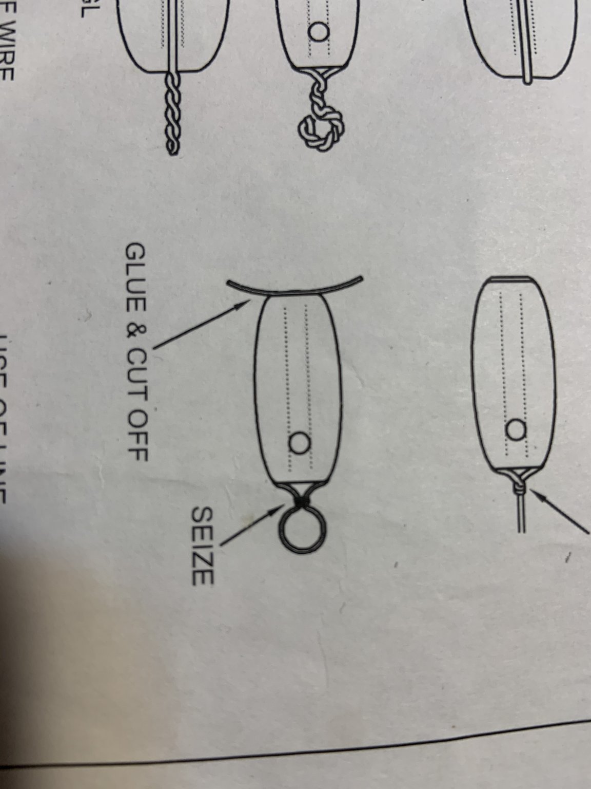
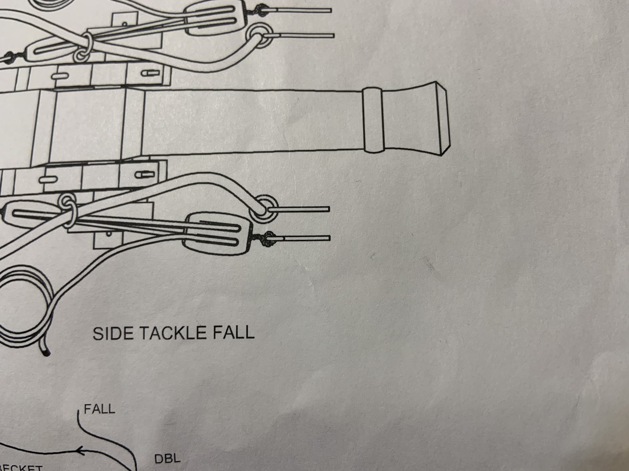
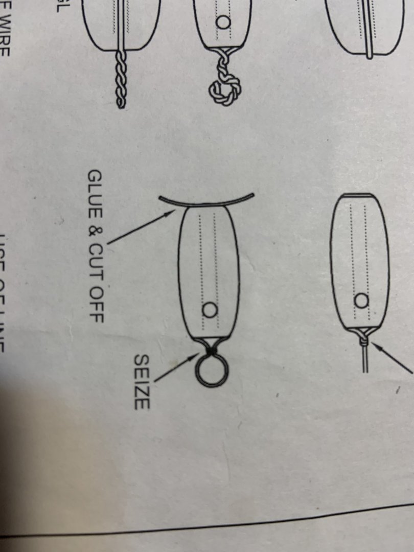
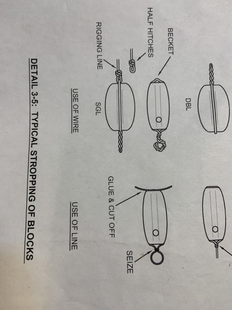
Hello all! I’m having great difficulty with this concept and am wondering if anyone has a solution? Essentially, I need to strop double blocks for rigging the cannons on my ship, but I am rather confused as to what happens to the end of the line. It seems like it is supposed to feed back into itself? That seems a little beyond my capabilities, but I’m very curious to see what others do. It’s something that’s so common, I don’t see the actual process mentioned very often, nor do I see it detailed much at larger scales. At a smaller scale, it’s a lot easier to give the illusion of a properly stropped block, but at this scale I am at a loss for how to proceed. Any help is greatly appreciated! Here are a couple pictures to illustrate what I mean. (I know, the last picture is definitely not the best way of doing it, right?)


-
I have the usual suspect textbooks: Lee, Marquardt, Zu Mondfeld, Davis. They have mast and yard length and diameter formulae for a number of nations but not Spain (except for Zu Mondfeld but his information is prior to the Napoleonic era and so not helpful .... Spanish spar formula probably changed with the surveyor). With the exception of the periods when the Spanish used English or French methods, is there a source of these formula? My books in Spanish, which I do not naturally read, all appear to provide information on Spars for actual ships (Frigate and above) and that just won't help me mast a brig though I do intend to work backwards and create formula that might be relevant to a brig. On the subject, a general book with Spanish plank sizes, hammock stancions, etc. would really help as well. I have several books by Enrique Garcia-Torralba Perez, books of photos of Museum ships, and a lot of original Royal plans and diagrams (many of which appear in said books as well), so that is how I have been picking up details but I really miss having sources like Goodwin and Lee. TYVM in advance!
-
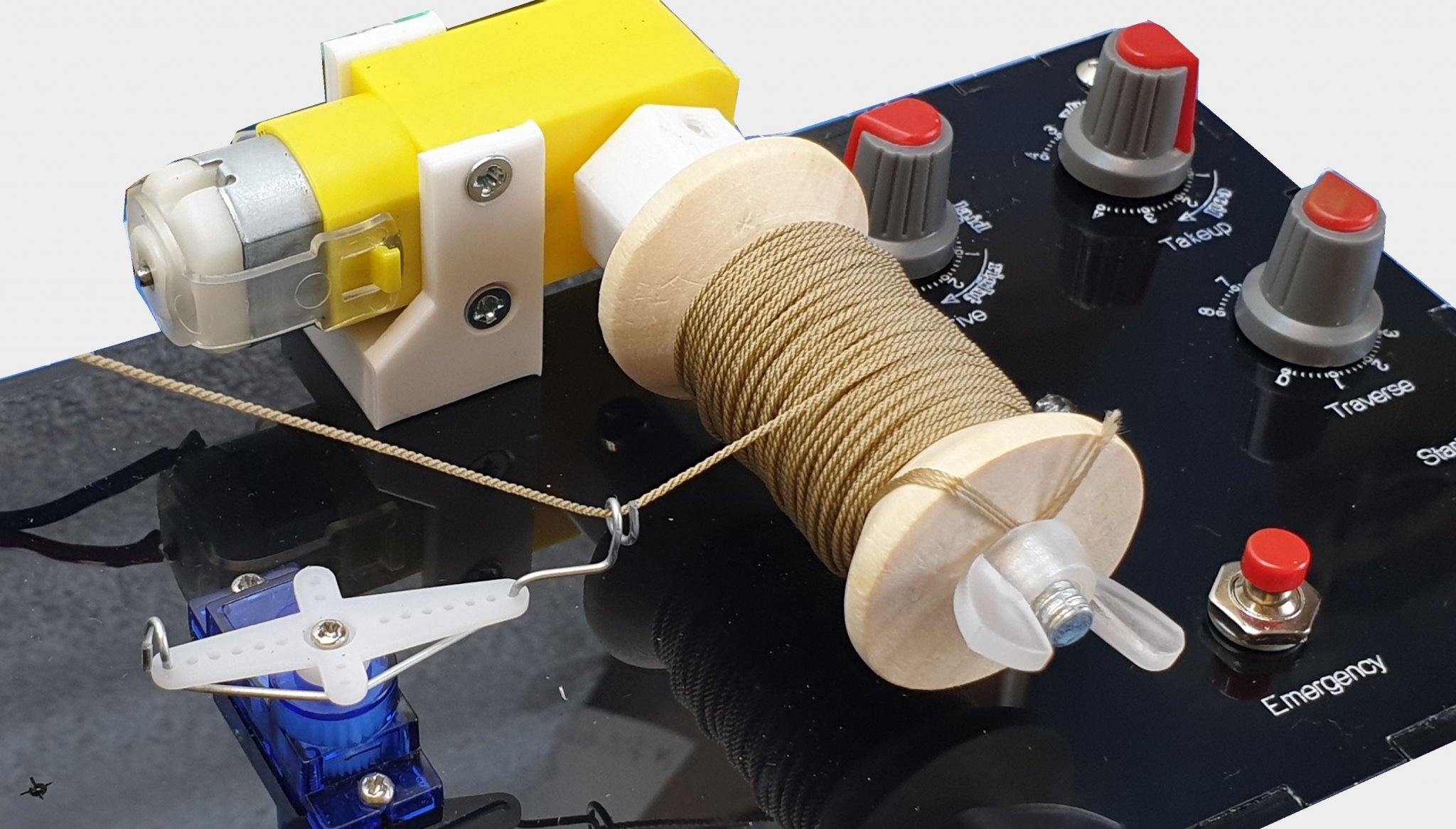
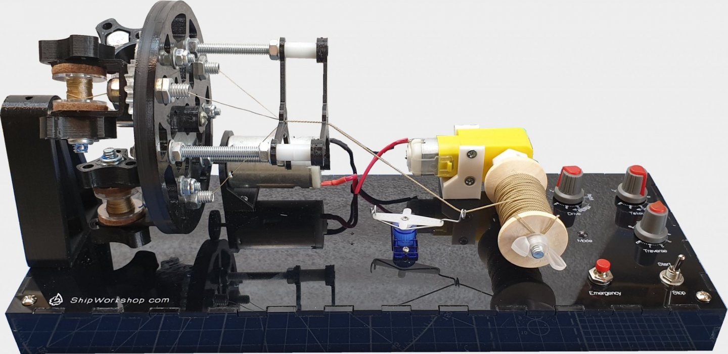
Dear All, I proud to present my new PL4 series rope making machines. How to operate on YouTube Full details on ShipWorkshop.com Basic features 2-, 3- or 4-stranded; With/without the core; Plain laid or cable laid; Left or right lay. Series members PL4-3: 2, 3 strands, no core; PL4-4: 2-4 strands, with core. PL3.2 successor; Choosing the right machine Please consider followings choosing the machine: PL4-3 makes 3-strand ropes and cables little bit better and easier than PL4-4. 4-strand ropes are rarely used on models and can be made using another tool like our VR series rope making machines. BR, Alexey

- 4 replies
-
- 13
-
-
- ropewalk
- rigging tools
- (and 1 more)
-
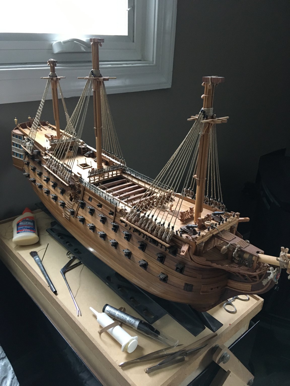
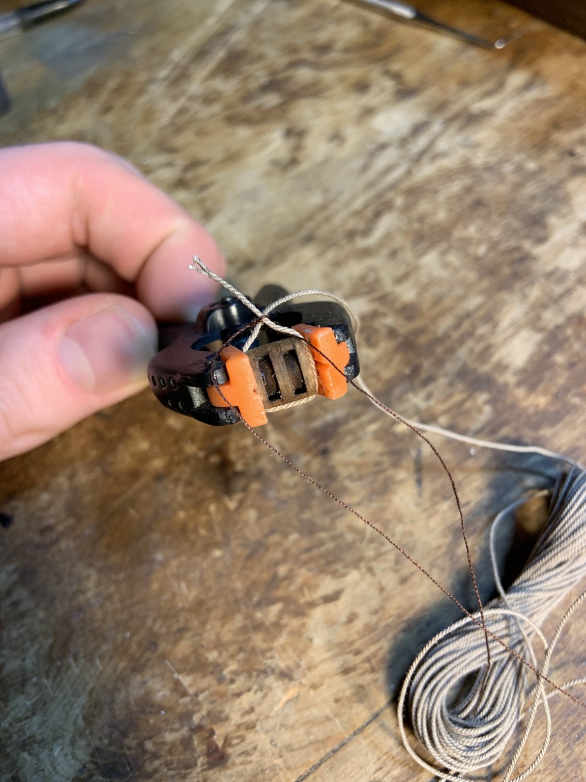
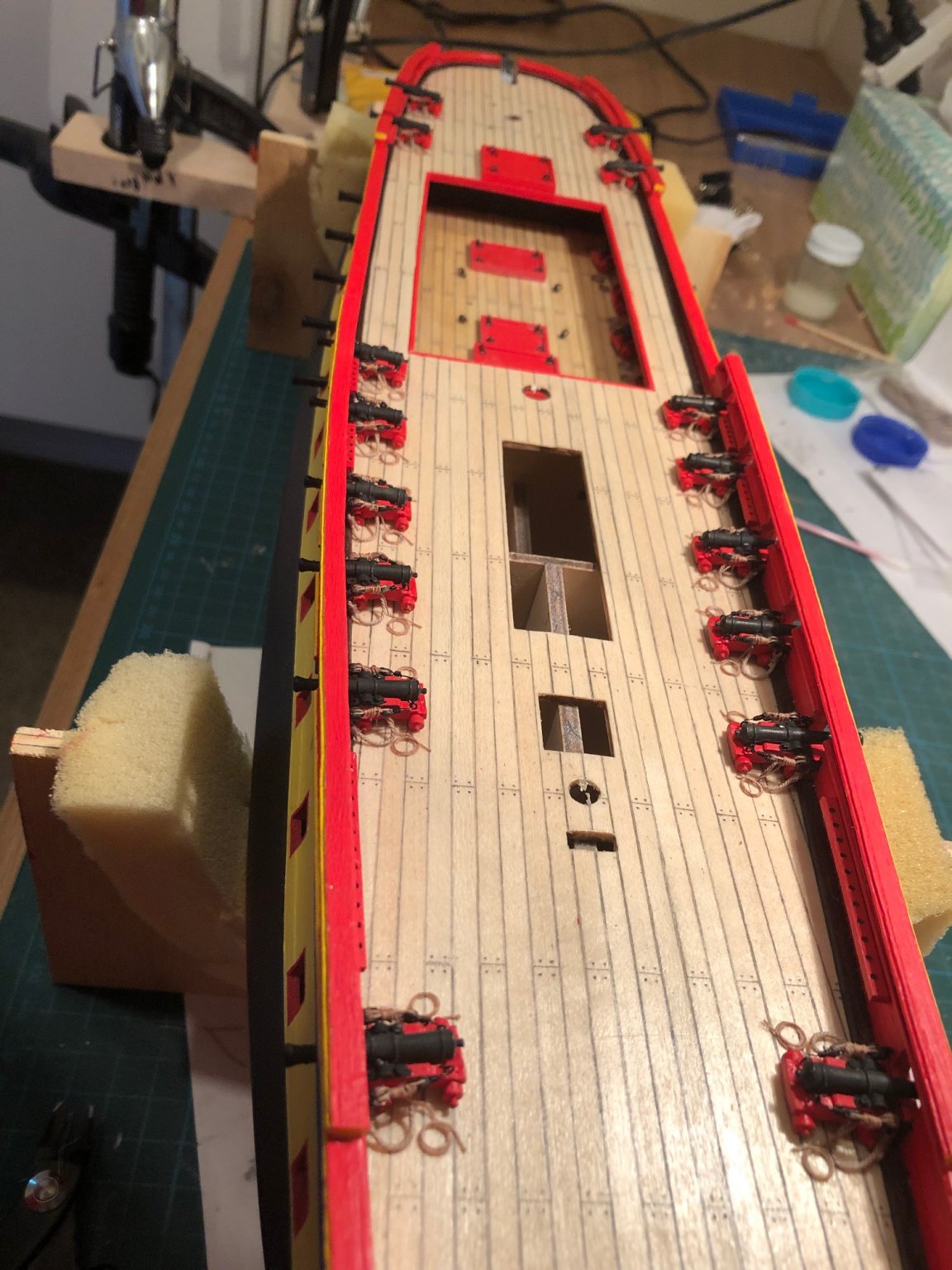
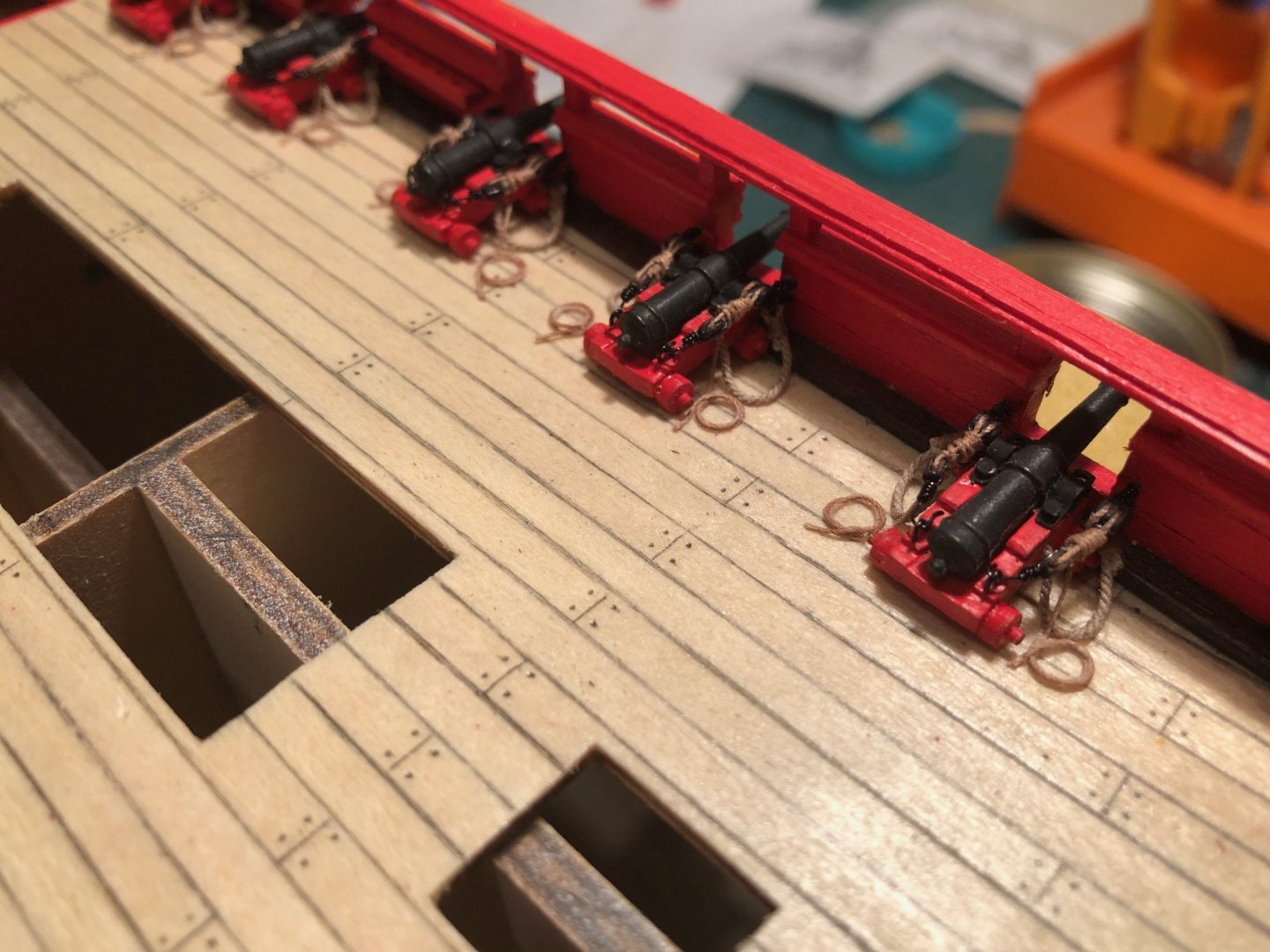
Well, after researching as much as I could from the many contributors to this and other forums regarding how cannon should be rigged I made the call. For the main deck 6-pounders I went with breaching lines and frapped block and tackle. I made the choice to coil a small amount of line at each side of the gun rather than try to have all the line taken up with frapping. Unfortunately I went with french coils next to unfrapped block and tackle on the 10 cannons that are visible on the gun deck. I guess I'll just need to direct any inspecting admiral to the gun deck as quickly as possible. I had used zip seizing on the block and tackle on both decks. That worked well and looked okay on the 12-pounders that didn't have frapped lines but it would have been better - and easier - to leave that seizing off the rigging that was going to be frapped. I think the look on the main deck is more of a ready-for-action look than the coiled lines. I plan to bend sails to some of the yards and have some furled or perhaps on clewlines. My hope is to give the appearance of a ship at sea rather than at anchor. Richard Current Build: AL L'Hermione

-
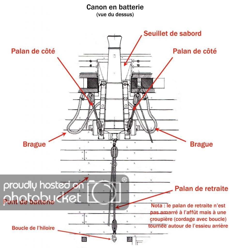
I'm new to this forum and new to model wooden ship building. I'm impressed by the expertise of the many contributors and a bit apprehensive about joining in. Everyone seems to have a good attitude of collaboration, so here goes. I'm building the Artesania Latina Hermione. The hull planking and painting are done and I'm about to install - ship - the ten cannons and carriages that are visible on the main deck. The AL instructions and illustrations show the installation of line that passes through the carriage (breaching line?) and is attached at both ends to the bulwork. As I look through various illustrations of the modern replica Hermione it's clear that there is at least one other rigging set present. That set is a line that passes through a set of blocks and is used for returning the cannon to its firing position. I'm thinking that would be a nice detail to add to my project. But, as I research this rigging a third set is often shown that extends from the rear of the cannon toward the midship line. What is that set for? I rarely, if ever, see that set in other models. Lastly, I'm I right in thinking that the French used a different arrangement than the British for how that breaching line is attached?