Search the Community
Showing results for tags 'longboat'.
-
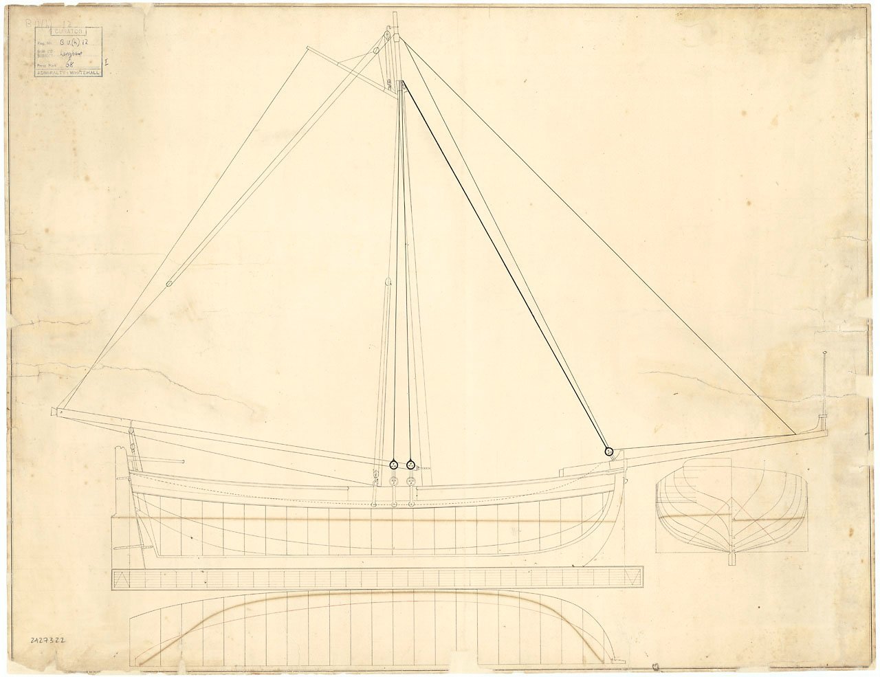
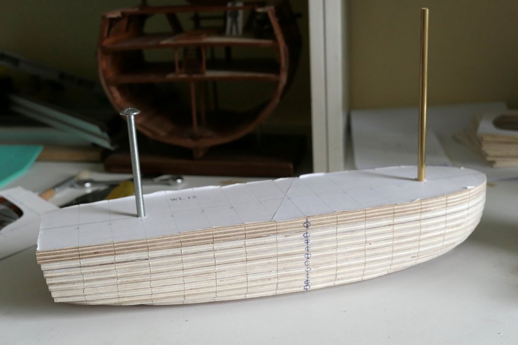
.thumb.jpg.6fd4c1b78768bb3efd745ab810936005.jpg) Now, I did not really intend to get involved in a project like this. My current boat (Deben 5 tonner) still needs a lot of work and has been going on for close to 4 years. However, this week I somehow found myself with a lot of free time to sit in front of a computer but not being able to work in the garage. I stumbled across the prints that the National Maritime Museum sells and there were some of boats carried by ships of the line that looked nice and detailed. I have always wanted to draft from printed lines and I ve been missing messing about with planks so I started playing with CAD. I just used the images the museum has on the on line shop. I progressed rather well, kind of 20% through the first lofting, so I thought I ll start a log initially with the CAD lofting and then with the boat it self, provided of course I ll get a reasonable result. Without a deck and rigging and with just a few planks it should not take more than 2 years to complete... I would like to try and do a nice lapstrake, not sure if it is historically accurate. Also, I cannot find easily much info on how these boats were actually built in terms of stringers, thwarts etch so I ll use some more modern arrangements and hope for the best, unless in the meantime I get by some more info. I admit I have not searched through MSW yet. I would like to try for a quality model, choosing appropriate wood, lining up holes, being careful with fit and finish etc. We ll see.. Enough talking, lets get down to business. This is the set of plans I used. The print costs £25 and can be ordered on line but as I said I just used the picture uploaded on the webisite. I think we are ok with copyright issues. More info on https://collections.rmg.co.uk/collections/objects/86936.html The plans show that this boat has a Davit but I will ignore this, at least for now as I do not really understand how it works. It seems like an interesting twist though. These plans are really very detailed. They include the keel, three WL, two diagonals, the sheer, all but the middle frames (this seems to be common practice) and also some of the interior arrangement. They proved later quite accurate and it is amazing that people can produce this with a ruler and a pencil. Especially the accuracy of the diagonals is impressive. Tracing the lines showed that there was slight distortion of the paper so adjustments had to be made. Getting all pieces in the correct position produced a half hull In the next photo, the sheer was created from the two views (red lines) provided in the plan. It fits the frames reasonably close. After I took this screenshot I had to re position all fore frames to account for the missing middle frame. This sorted things out. Later on I also found a small mistake and correcting it raised all the frames a bit. These is the top view of the waterlines. A bit of effort was needed to get them somewhat fair And on to the hull...not too bad. The diagonals (blue) are also added The sheer seems reasonably fair. This is the only line that really needs to be fair as it will not change and will be a reference line. All other lines except maybe the diagonals will change during the lofting cycles. The waterlines are also faired but these will get adjusted many times The hull with just the lines. Note that the transom in the plans is given in its vertical projection. It first needs to be projected in the angled plane it would normally be prior to adding to the hull This concluded the first part which is to just get all lines drawn. Now, the first lofting cycle begins. I created two more WL to help me maintain the shape of the frames in the upper strakes (green colour) I decided that the diagonals are the more accurate lines and I will follow these, using the WLs to maintain the shape of the frames. This is how I arranged the new shape and how much off the frame was. Not too much really. The small horizontal lines were added to maintain the distance from the old line, so keeping the same shape as close as possible. Later on, the WLs will be created anew and faired and the cycle will begin again. In the next two photos, you can see that the frames on the left side that have been faired follow the lines much closer than the rest Now we can try and create a bit of surface with the frames we have adjusted and see how it looks and how smooth it is. The points and lines from adjusting the 5th frame can be seen in the background. This is not bad at all considering that the waterlines have not been faired back at all. Of course the difficult areas will be first the two segment at the bow and possibly the transom. To my experience the transom always creates problems! It looks promising though. I am not sure when I ll have time to do any more work on this but it has been fun. If I ever manage to build this it will be a big baby at 640 mm LOA, some planks will be close to 80 cm long! Off to a very busy weekend, I will be doubling the lighting in my garage, it should be as bright as a supenova afterwards. Regards Vaddoc
Now, I did not really intend to get involved in a project like this. My current boat (Deben 5 tonner) still needs a lot of work and has been going on for close to 4 years. However, this week I somehow found myself with a lot of free time to sit in front of a computer but not being able to work in the garage. I stumbled across the prints that the National Maritime Museum sells and there were some of boats carried by ships of the line that looked nice and detailed. I have always wanted to draft from printed lines and I ve been missing messing about with planks so I started playing with CAD. I just used the images the museum has on the on line shop. I progressed rather well, kind of 20% through the first lofting, so I thought I ll start a log initially with the CAD lofting and then with the boat it self, provided of course I ll get a reasonable result. Without a deck and rigging and with just a few planks it should not take more than 2 years to complete... I would like to try and do a nice lapstrake, not sure if it is historically accurate. Also, I cannot find easily much info on how these boats were actually built in terms of stringers, thwarts etch so I ll use some more modern arrangements and hope for the best, unless in the meantime I get by some more info. I admit I have not searched through MSW yet. I would like to try for a quality model, choosing appropriate wood, lining up holes, being careful with fit and finish etc. We ll see.. Enough talking, lets get down to business. This is the set of plans I used. The print costs £25 and can be ordered on line but as I said I just used the picture uploaded on the webisite. I think we are ok with copyright issues. More info on https://collections.rmg.co.uk/collections/objects/86936.html The plans show that this boat has a Davit but I will ignore this, at least for now as I do not really understand how it works. It seems like an interesting twist though. These plans are really very detailed. They include the keel, three WL, two diagonals, the sheer, all but the middle frames (this seems to be common practice) and also some of the interior arrangement. They proved later quite accurate and it is amazing that people can produce this with a ruler and a pencil. Especially the accuracy of the diagonals is impressive. Tracing the lines showed that there was slight distortion of the paper so adjustments had to be made. Getting all pieces in the correct position produced a half hull In the next photo, the sheer was created from the two views (red lines) provided in the plan. It fits the frames reasonably close. After I took this screenshot I had to re position all fore frames to account for the missing middle frame. This sorted things out. Later on I also found a small mistake and correcting it raised all the frames a bit. These is the top view of the waterlines. A bit of effort was needed to get them somewhat fair And on to the hull...not too bad. The diagonals (blue) are also added The sheer seems reasonably fair. This is the only line that really needs to be fair as it will not change and will be a reference line. All other lines except maybe the diagonals will change during the lofting cycles. The waterlines are also faired but these will get adjusted many times The hull with just the lines. Note that the transom in the plans is given in its vertical projection. It first needs to be projected in the angled plane it would normally be prior to adding to the hull This concluded the first part which is to just get all lines drawn. Now, the first lofting cycle begins. I created two more WL to help me maintain the shape of the frames in the upper strakes (green colour) I decided that the diagonals are the more accurate lines and I will follow these, using the WLs to maintain the shape of the frames. This is how I arranged the new shape and how much off the frame was. Not too much really. The small horizontal lines were added to maintain the distance from the old line, so keeping the same shape as close as possible. Later on, the WLs will be created anew and faired and the cycle will begin again. In the next two photos, you can see that the frames on the left side that have been faired follow the lines much closer than the rest Now we can try and create a bit of surface with the frames we have adjusted and see how it looks and how smooth it is. The points and lines from adjusting the 5th frame can be seen in the background. This is not bad at all considering that the waterlines have not been faired back at all. Of course the difficult areas will be first the two segment at the bow and possibly the transom. To my experience the transom always creates problems! It looks promising though. I am not sure when I ll have time to do any more work on this but it has been fun. If I ever manage to build this it will be a big baby at 640 mm LOA, some planks will be close to 80 cm long! Off to a very busy weekend, I will be doubling the lighting in my garage, it should be as bright as a supenova afterwards. Regards Vaddoc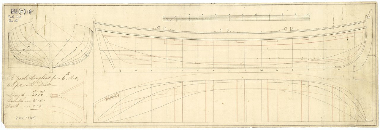
cropped.thumb.png.64da0c5486f4900ffd7b9dd417d293d4.png)
cropped.thumb.png.21f1d4a3a7b7261b0230e00e4ee0d907.png)
cropped.thumb.png.a8425a74bc480511f7716eecb3c446c9.png)
cropped.thumb.png.f588130825940cec6cfeb5905c84e774.png)
cropped.thumb.png.3aa8727d55571d503c61ee5d3f92e916.png)
cropped.thumb.png.3891bad48a5de6dde675c9eb7bb2e066.png)
.thumb.png.96fcc1de9fad79d4fe1e1c1ea7fc3436.png)
.thumb.png.e0093a2684c49af39dcfd5f05abe2ab3.png)
.thumb.png.85e73955249e7eeb71251718fd8aa2df.png)
.thumb.png.9d443c094c267acfedb70cef880bf88c.png)
.thumb.png.62f659e540c08174a003759f7b2ddf6f.png)
.thumb.png.88bc753c0e2f6aba3245942b711b5c30.png)
.thumb.png.d2c873e98758556488fd74334ccd7dc2.png)
.thumb.png.7d5d832dbaa5fd2b7e4296680a7588f6.png)
.thumb.png.8d256c385d136b48dde0eeca245d3050.png)
.thumb.png.5ab2c4518720341024e6eb690163b821.png)
- 232 replies
-
- 18
-

-

-
 Another builder commented about the difficulty of building a small boat with details at this small scale, and I agree but I took it as a challenge. It may never get finished or may not wind up looking very good, but I thought it would be a quick little fun project to attempt to see if I could do it. I am sure there are a LOT of members that could accomplish the task, but a lot more that will share my pain as I move forward. I am starting with RMG plans ZAZ5814, dated May 1801. There are a number of items about which I have had questions and that have been discussed here at MSW. I have also put together scantlings based on what I could glean from the drawing and from the scantlings of circa 1800 given in W. E. May's The Boats of Men of War. I also downloaded plan ZAZ 7322 for details on the rigging that will come later. Scantlings can be seen in the attached PDF. If anyone wants the Excel version, please feel free to PM me. I have included full size dimensions as well as dimensions at 1:96 in imperial and metric. Scantlings (version 1).xlsb.pdf I downloaded the plans and resized to 1:96 scale then drew up plug pieces below using the body plan. I printed these on label paper then attached them to wood that was planed to a thickness of 0.156", the distance from station to station. The building board for the plug and some of the cut out plug pieces are in the photo below. (NB: I put a station "I" on the board but it should be the letter "H") The XAZ5814 actually show these to be cant frames Allan
_RMG_J0267.thumb.png.fac31f89a114b33325d67cd8874b7d4e.png)

-
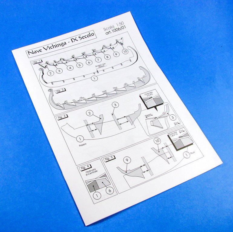
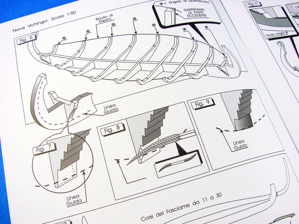
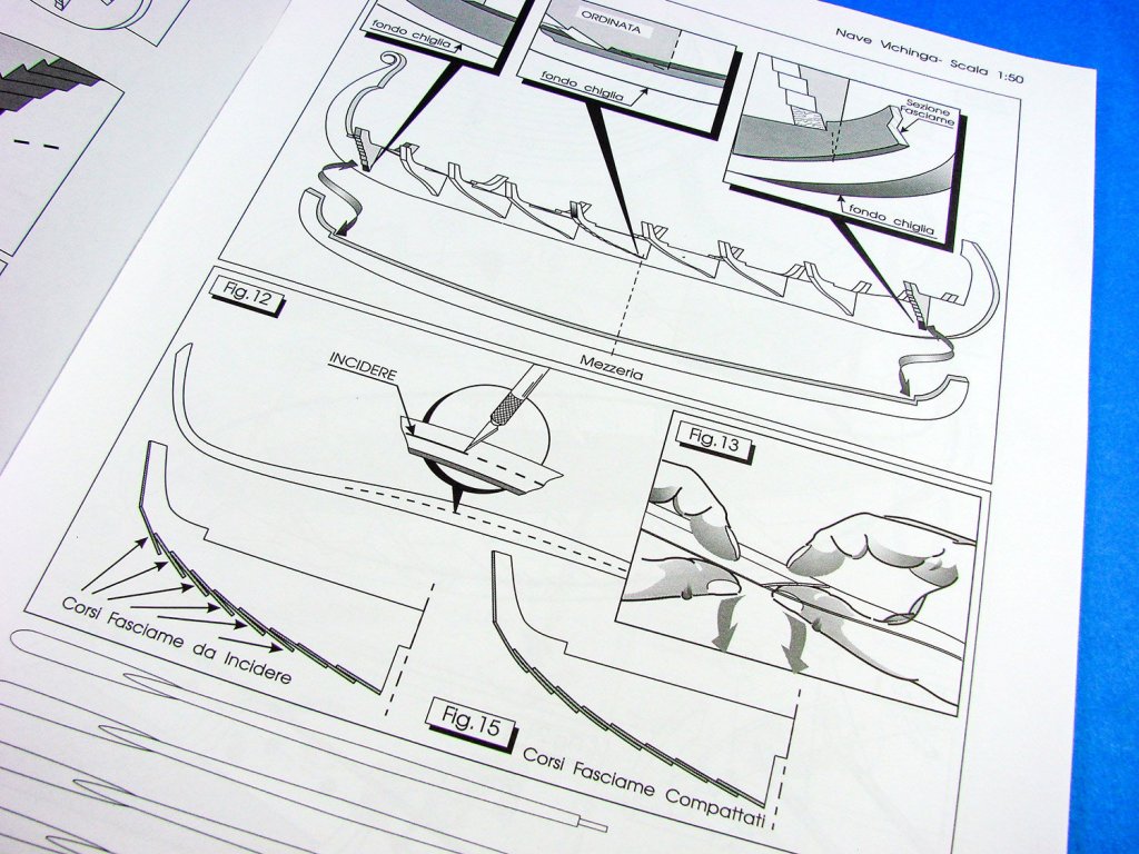
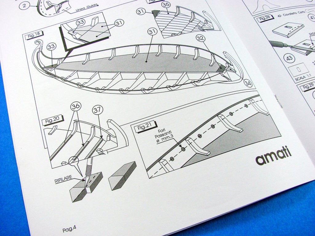
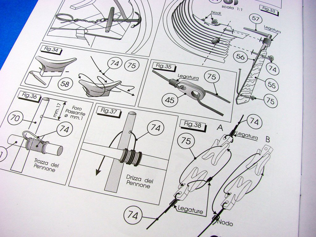
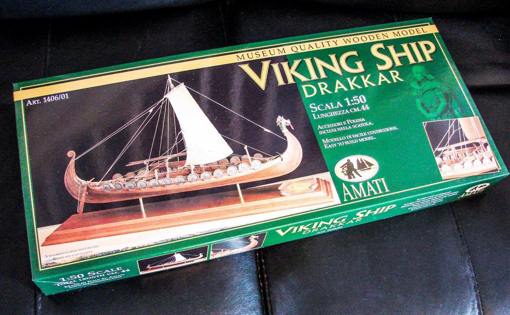
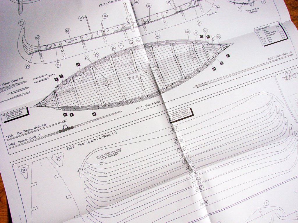
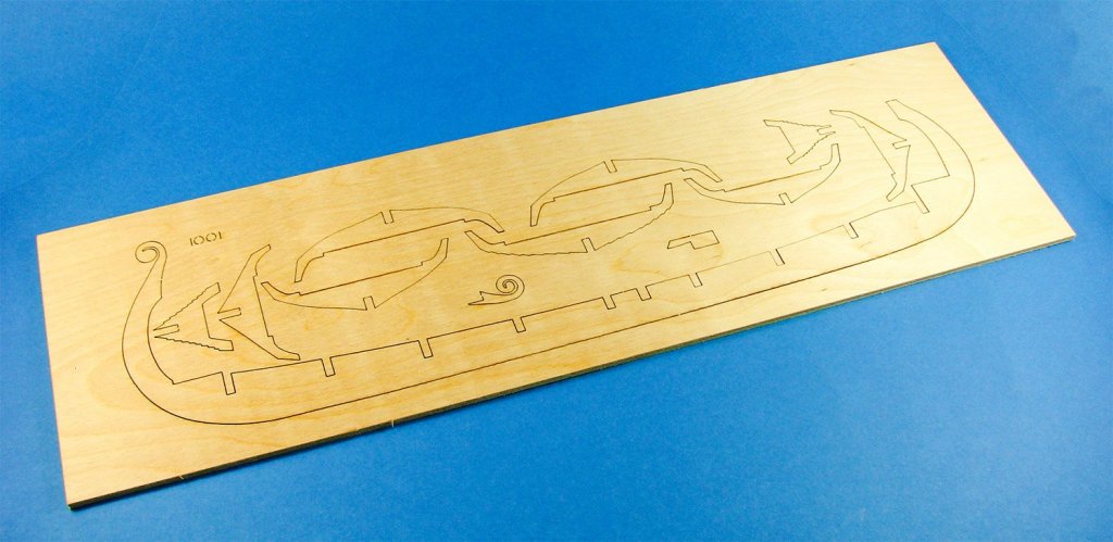
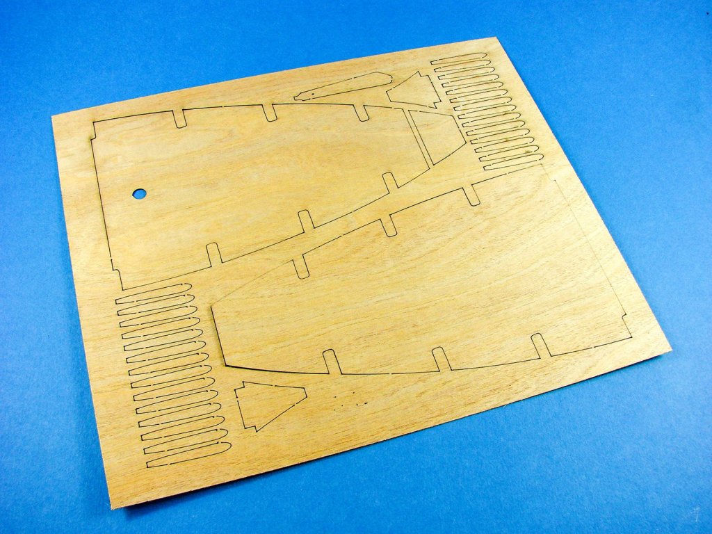
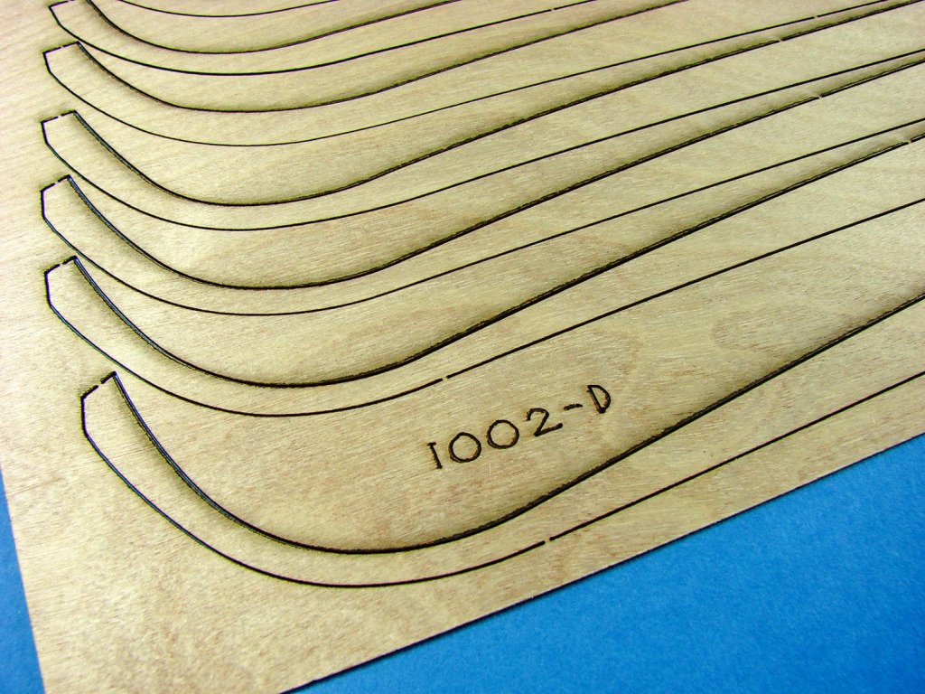
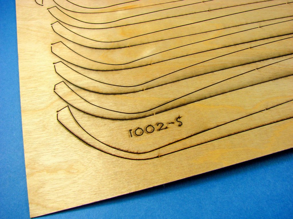
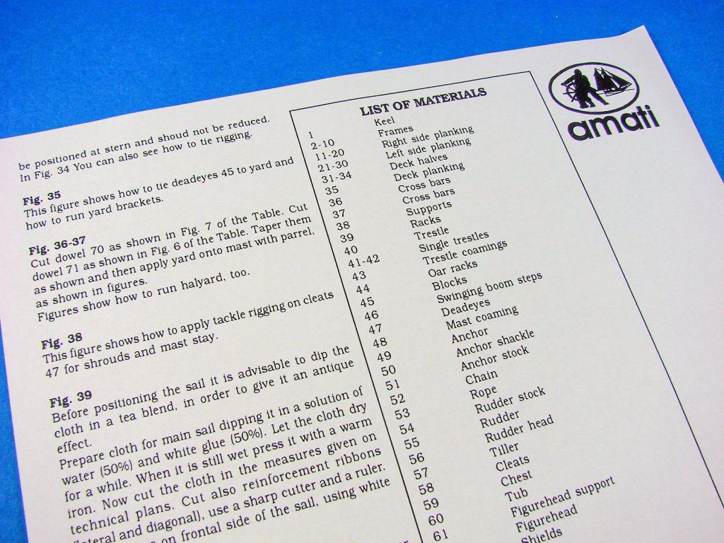
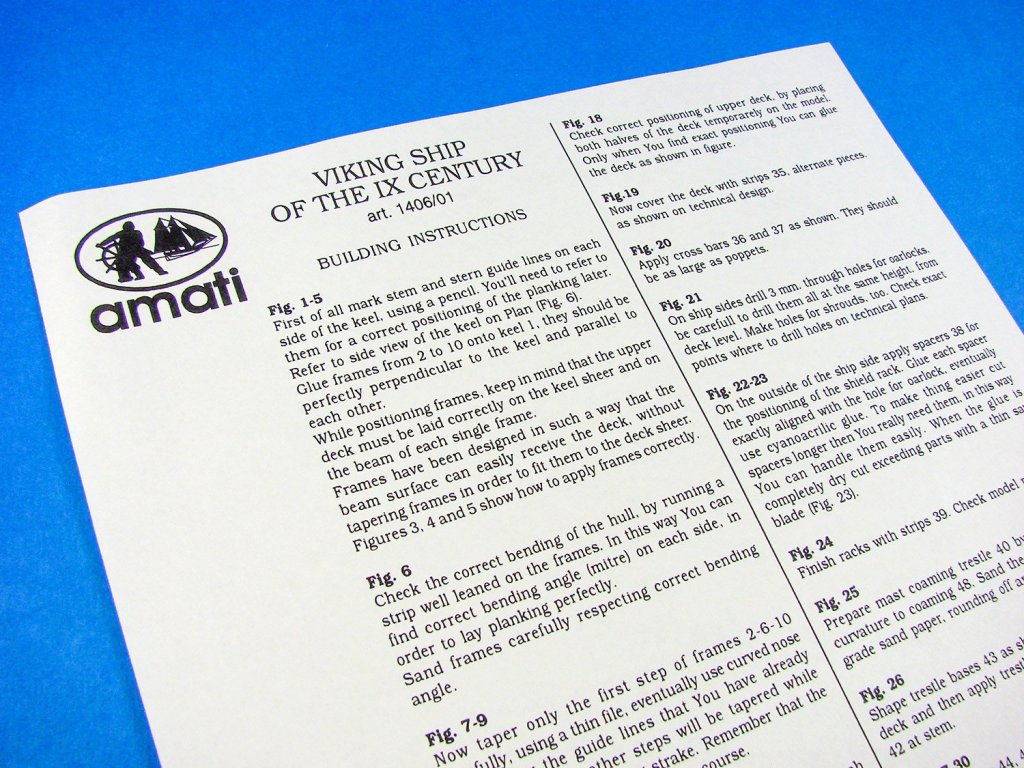
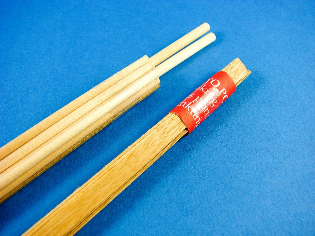
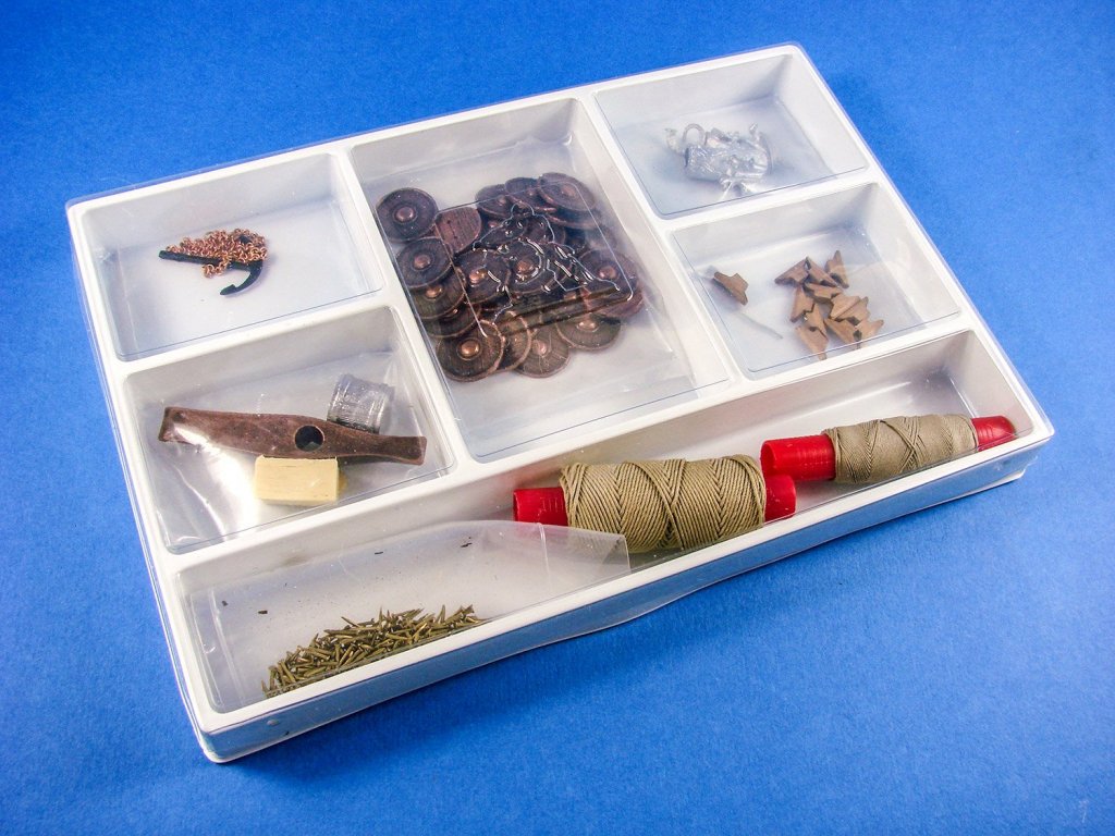
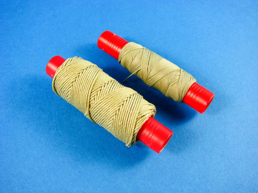
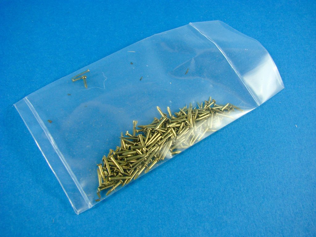
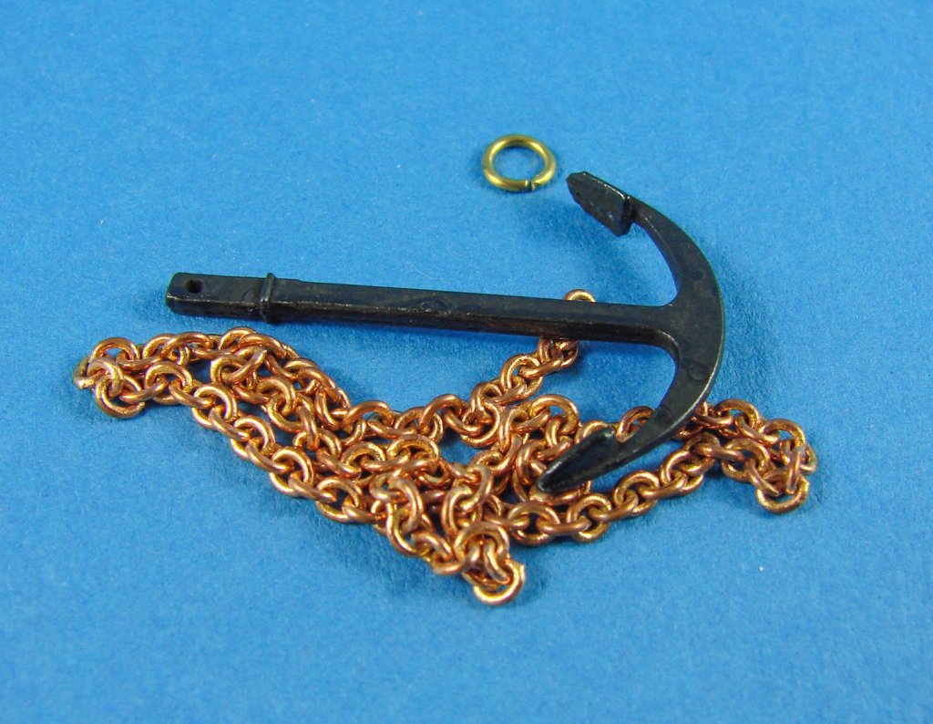
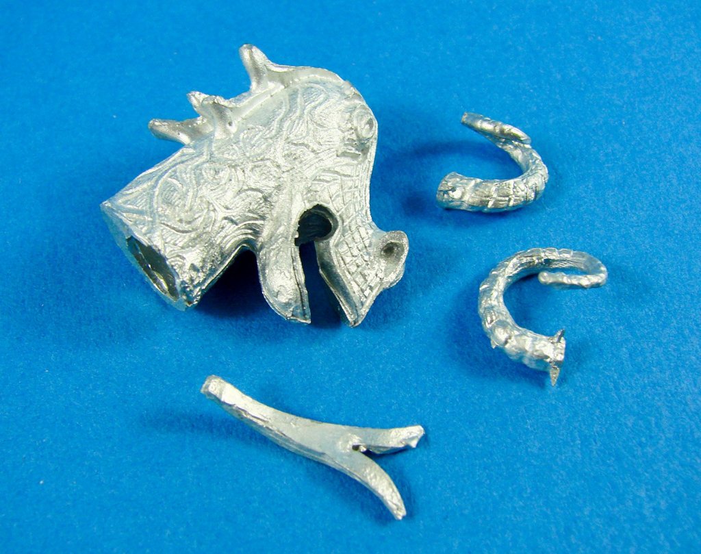
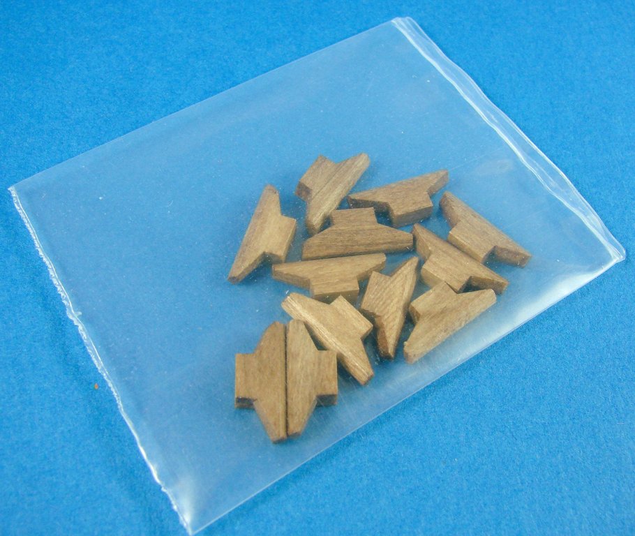
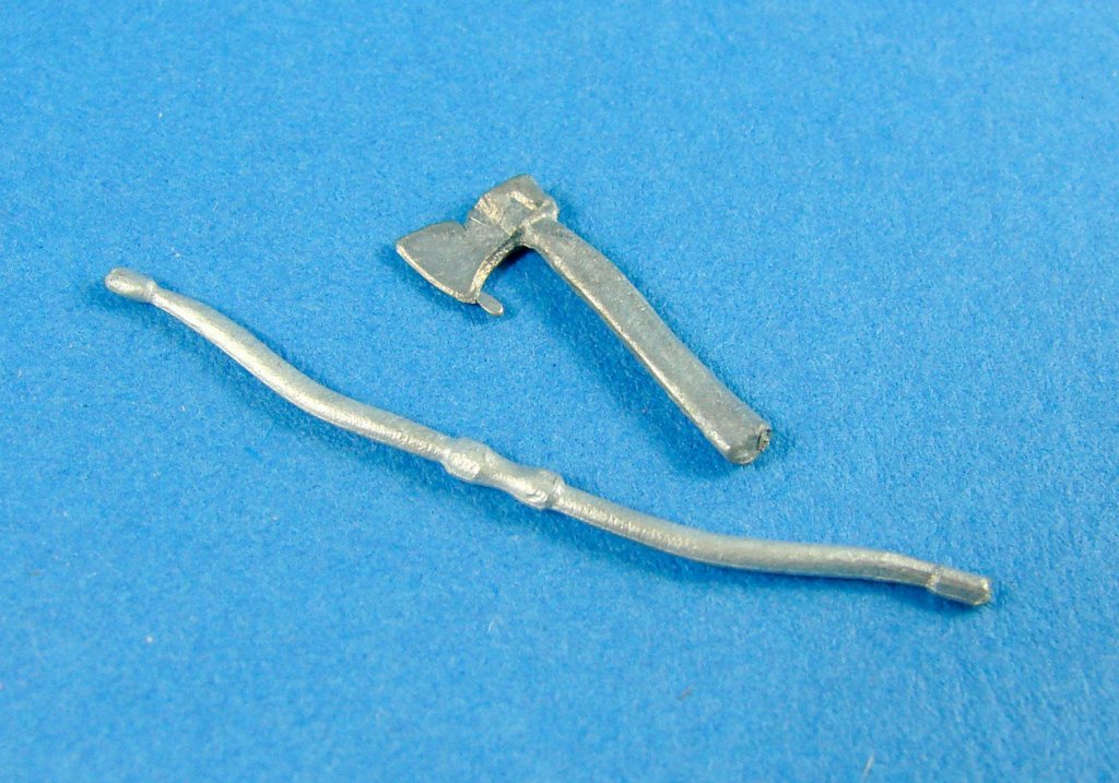
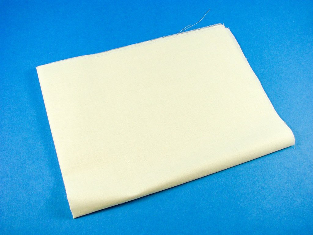
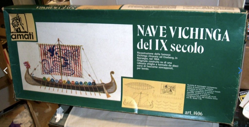
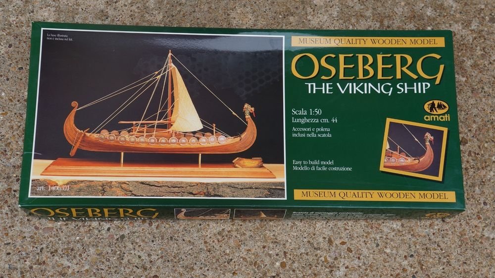
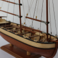
1/50 Viking Longship – Drakkar Amati Catalogue # 1406/01 Longships were a type of ship invented and used by the Norsemen (commonly known as the Vikings) for commerce, exploration, and warfare during the Viking Age. The longship's design evolved over many centuries, beginning in the Stone Age with the invention of the umiak and continuing up until the 6th century with clinker-built ships like Nydam and Kvalsund. The longship appeared in its complete form between the 9th and 13th centuries, and the character and appearance of these ships have been reflected in Scandinavian boat-building traditions until today. The particular skills and methods employed in making longships are still used worldwide, often with modern adaptations. They were all made out of wood, with cloth sails (woven wool) and had numerous details and carvings on the hull. Longships were characterized as a graceful, long, narrow and light, with a shallow-draft hull designed for speed. The ship's shallow draft allowed navigation in waters only one meter deep and permitted arbitrary beach landings, while its light weight enabled it to be carried over portages or used bottom-up for shelter in camps. Longships were also double-ended, the symmetrical bow and stern allowing the ship to reverse direction quickly without a turnaround; this trait proved particularly useful at northern latitudes, where icebergs and sea ice posed hazards to navigation. Longships were fitted with oars along almost the entire length of the boat itself. Later versions had a rectangular sail on a single mast, which was used to replace or augment the effort of the rowers, particularly during long journeys. Drakkar are only known from historical sources, such as the 13th-century Göngu-Hrólfs saga. Here, the ships are described as elegant and ornately decorated, and used by those who went raiding and plundering. These ships were likely skeids that differed only in the carvings of menacing beasts, such as dragons and snakes, carried on the prow of the ship. These carvings allegedly protected the ship and crew and warded off the terrible sea monsters of Norse mythology. It is however likely that the carvings, like those on the Oseberg ship, might have had a ritual purpose, or that the purported effect was to frighten enemies and townspeople. No true dragon ship, as defined by the sagas, has been found by archaeological excavation. Extract from Wikipedia The kit This isn’t a new kit, and in fact I know this was once released under the name Oseberg Viking Ship, again by Amati, some years ago. I know there to have been at least two boxings of this over the years. In fact, some vendors still have it listed as this, or may even carry that older kit in stock. I’m unsure as to when the kit changed its name to the current Drakkartitle. The kit itself comes in a high quality, glossy and attractive box, carrying a colour image of the profile of the vessel on the lid, and accompanying small detail photo. It can be seen on the lid that the 1/50 scale equates to 44cm length. Inside the box, Amati has given some strength to the packaging my adding a card shelf to make the interior shallower and preventing the contents from rattling around because there is surprisingly little timber by the way of sheets, than you might expect due to the way Amati has approached the design. A Plywood sheet contain the keel which incorporates the curved bow and stern, plus also the nine bulkheads that are notched to match their respective positions on the keel. As you see, the construction is quite traditional in this respect, and the shallow draught of the ship is the reason for a relatively low number of ply sheets. Now, whilst there is of course some strip stock in this kit, the ship’s planking isn’t associated with this. Instead of what would be a rather complicated method of planking, this particular model is provided with two sheets of thin, laser-cut planks which are perfectly shaped to follow the contours of the hull, and also sit within the stepped recesses of the bulkheads. These planks are produced from very thin plywood and just require the scorched edges of the parts gently sanded and then sitting into the recesses. Those bulkhead recesses will need to be slightly sanded for the planks to fully conform, and most definitely at both stem and stern. This is clearly shown in the accompanying instruction manual. It is also necessary, again shown on the instructions, to trace a curve to stem and stern, which sets the line against which to plank to. Also presented in plywood is the main deck, in two large main pieces, and three small sections. With the model planked and the tops of the bulkheads previously sanded to conform to the keel, these can be attached and then planked with the supplied strip stock. Deck planking is done in short pieces that only span between each former. I’m pretty sure that these sections could be removed on the real thing, and tools, weapons and food stored in the void below. Strip wood stock is included for the deck planking, and dowel for the mast and oars. Timber quality is excellent, with tape holding together the various bundles. A smaller piece of walnut sheet is also included, and this contains parts for the rudder paddle, oar storage frames, rigging blocks, belaying posts and bases etc. Laser cutting quality is nice and fine with only minimal timber to snip through to release each part. For protection, all timber sheets are placed in a thick, clear sleeve, as are the instructions manual and plans. Fittings Sitting on top of the timber sheet is a vac-form plastic box with a removable clear lid. The box has six compartments holding a few loose wooden pieces, rigging cord, as well as the metal fixtures and fittings for the Drakkar. The small number of loose wooden pieces are for the cleats. These just need a little final shaping before use. A large bag of metal shields is included, with their respective bosses and timber details cast in situ. I’m unsure as the metal for these, but they aren’t white metal, and possibly some alloy. They have also been given an aged finish, but I would carefully paint these to make them look more realistic. A single anchor is provided in metal, utilising a wooden stock, and a small length of brass chain is provided for this. A small number of cast white metal parts are included, and these are for the ship’s dragon head (with separate horns and tongue) and a deck bucket (slop outtoilet?), longbow, axe etc. The casting here is very nice and when painted, should really look the part. A bag of brass nails is included, and these are well-formed and sharp, unlike some I’ve used over the years. You are best drilling a small pilot hole before applying these, so you don’t split any timber when you drive them through the hull planks and into the bulkheads. As Viking Drakkar were of a very shallow draught, the mast needed something substantial to hold it in place. Under the deck would have been a keelson to locate the base of the mast, but above deck, this was achieved via a hefty wooden block. That had a wedge as part of its structure. As far as I can tell, these were called the mastfish and wedge, respectively. For some seriously interesting information on these vessels, check out this link: http://www.hurstwic.org/history/articles/manufacturing/text/norse_ships.htm As well as two sizes of rigging cord for standard and running rig, a piece of sailcloth is also included. You will need to make the sail yourself, including the diagonal strips that run at 90 degrees to each other. You need to sew along the edges after folding them in, replicating the looping stitch that should be seen. One thing you’ll need to do is to buy some fabric paint for the sail stripes. Aging the sail can be done with the age-old method of soaking in tea, should you wish. However, another method is to soak in a Potassium Permanganate (KMNO4) solution. Only a little is needed, and you can gauge the finish on a test piece as the colour develops when you remove from the solution. Also included is a chest that can be sat on the deck as extra detail. This is cast from a cream-coloured resin. Plans and instructions Amati include an 8-page basic instruction manual for this model, guiding you through the principle steps of the model and explaining the various key areas of construction. Illustrations are in line drawing format and are clear to understand, despite the Italian text. A separate sheet with English annotation is also supplied for those of us who haven’t grasped the rudimentary elements of that beautiful language. Of course, a plan is also included for the model which describes things in greater detail, including the rigging stages. This is also typically easy to understand and also contains the shapes for a good number of kit parts, so if you were to screw up, then with a little extra timber, you can right your wrongs. Conclusion As I originally stated, this isn’t a new kit, but it is one that has stood the test of time and for me, still ranks as the best-looking Drakkar you can buy in kit form, and certainly the most authentic in appearance. I know some people don’t like the plywood planking, but as you shouldn’t need to thin the planks much (if at all), then this doesn’t feature as an issue for me. Some timber edges will need to have the charring from the laser cutting removed, but again, this isn’t a problem as far as I’m concerned. Amati has designed this kit to be relatively straightforward and they have succeeded. As far as price goes, it can vary, but I’ve seen in in the UK/EU for around £90 to £100. I’ll start my own building log of this on Model Ship World very shortly. My sincere thanks to Amati for sending this kit out for review here on MSW.


- 15 replies
-
- 11
-
-
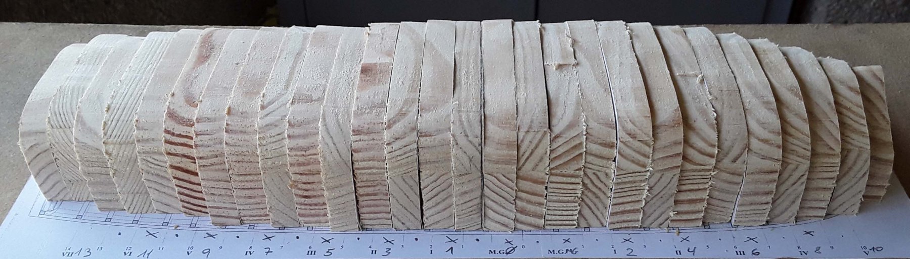
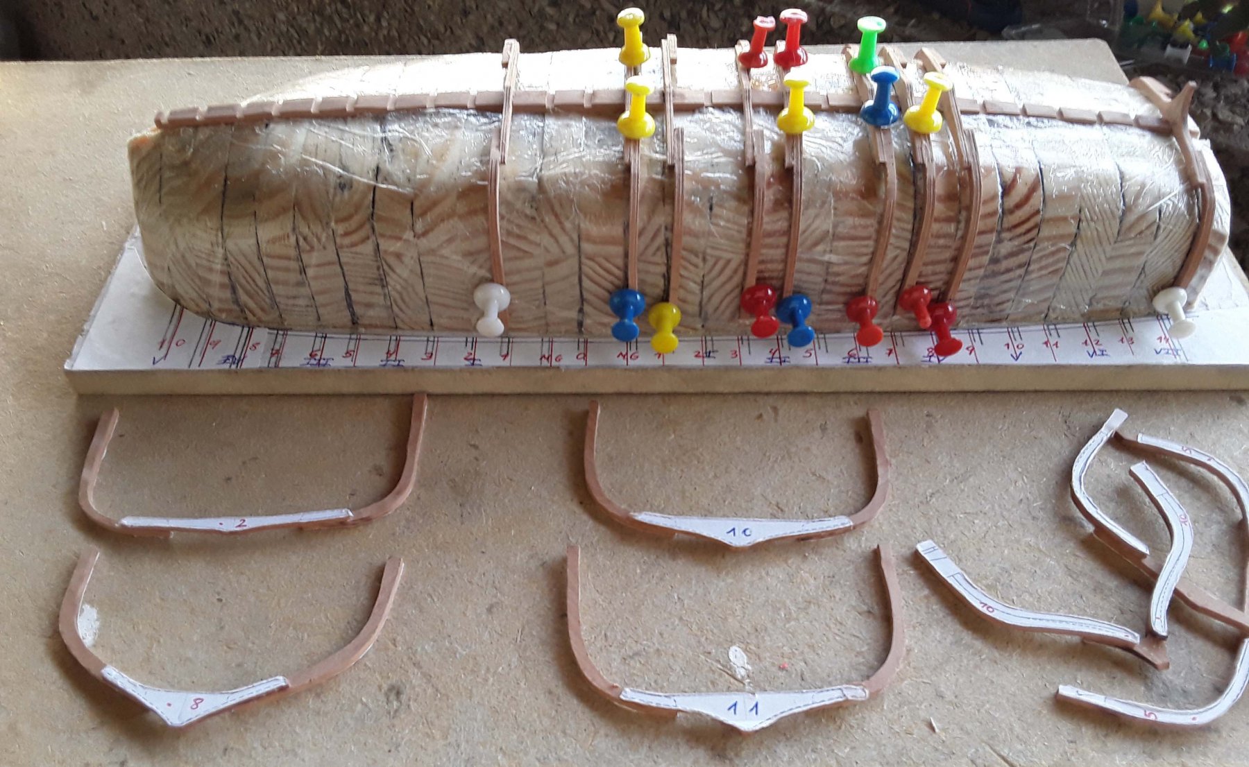
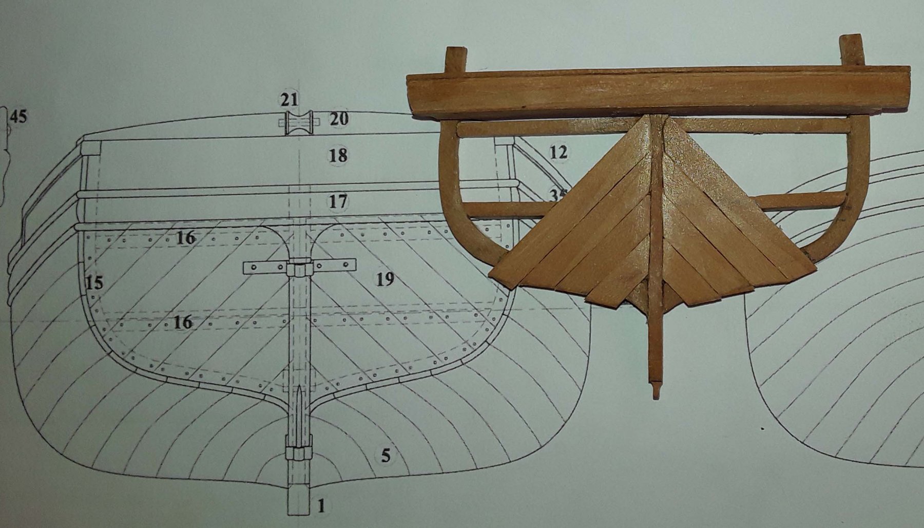
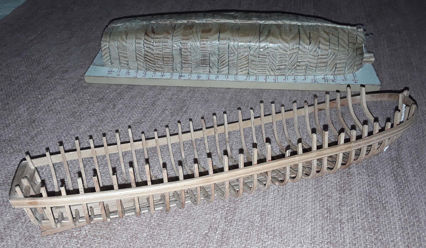
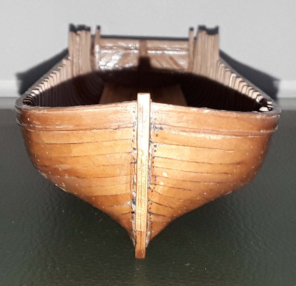
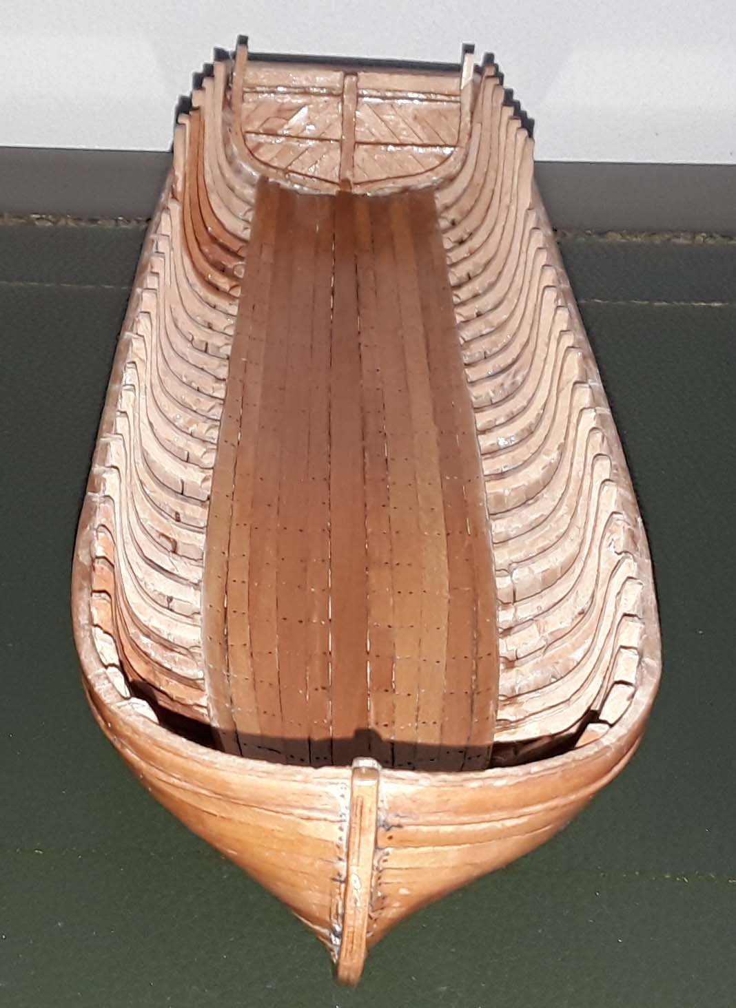
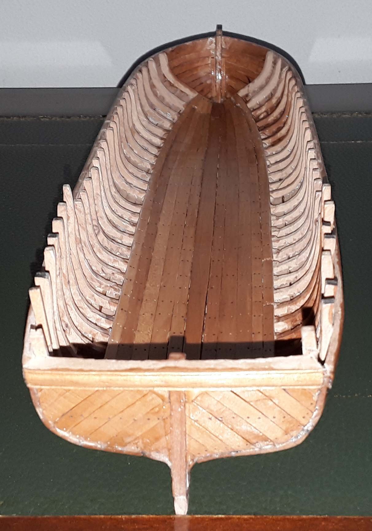
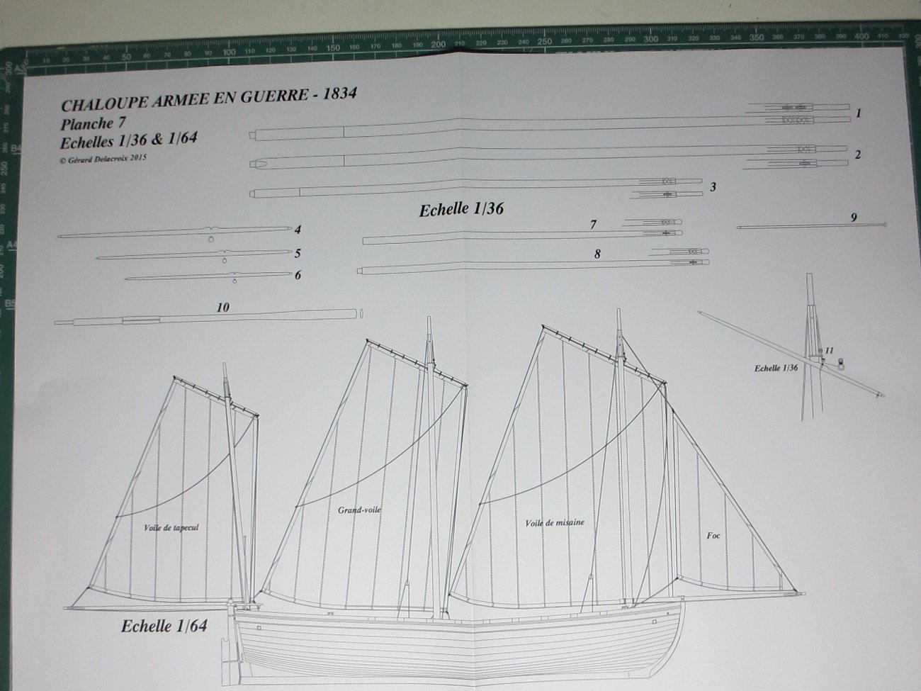
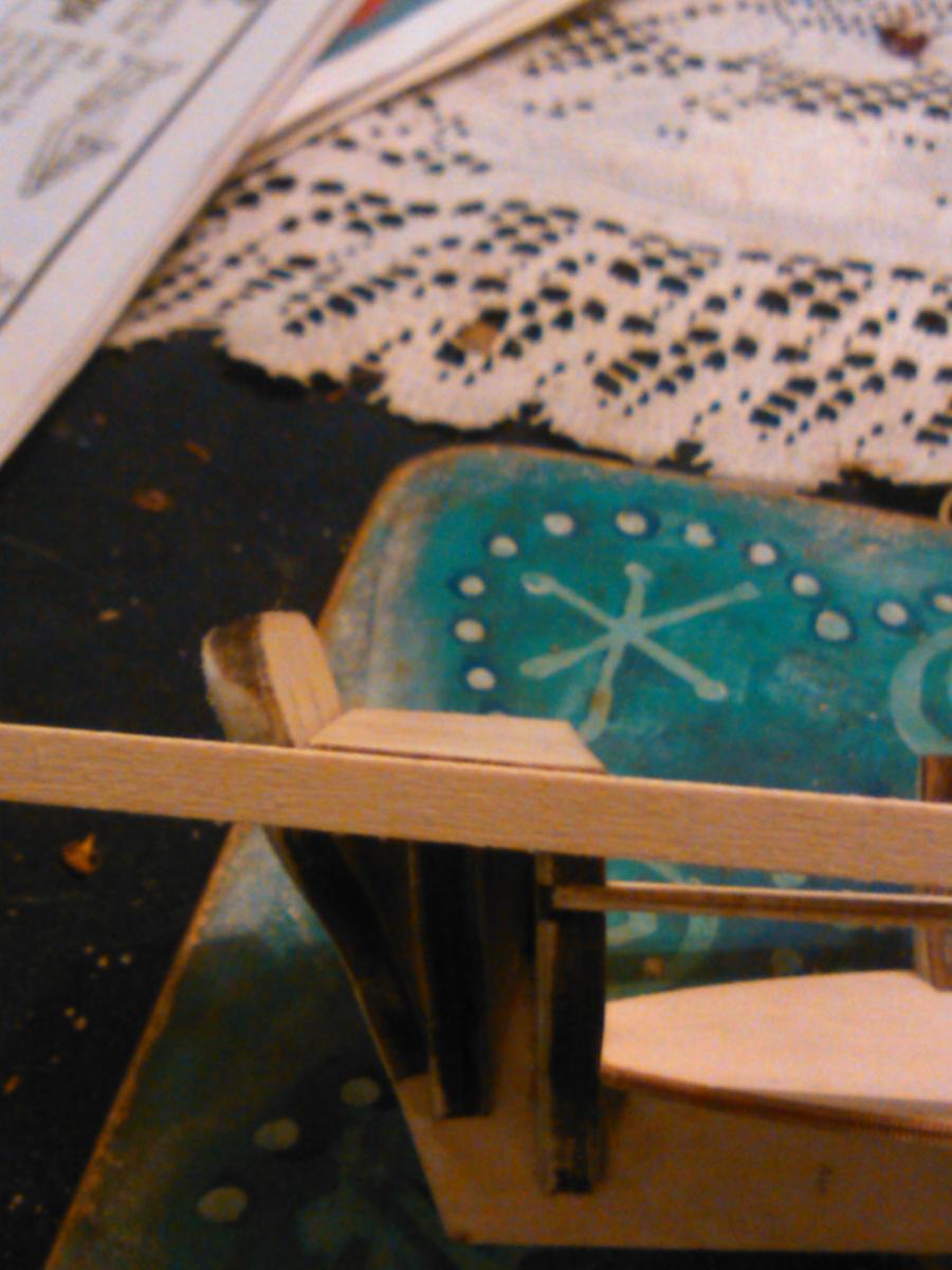
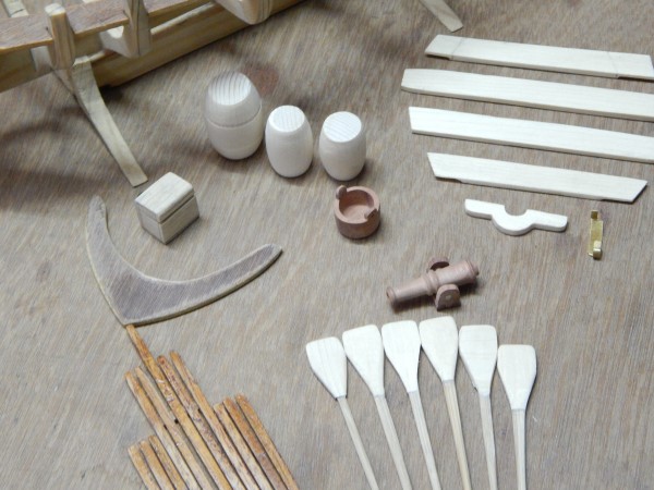
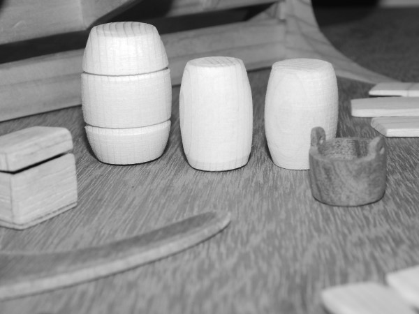
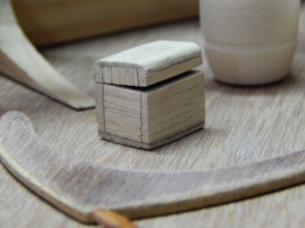
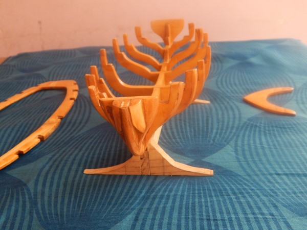
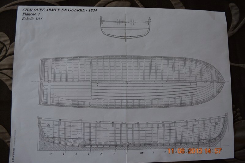
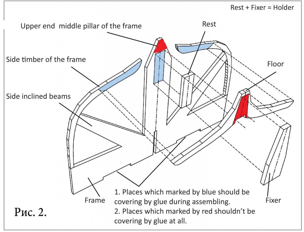
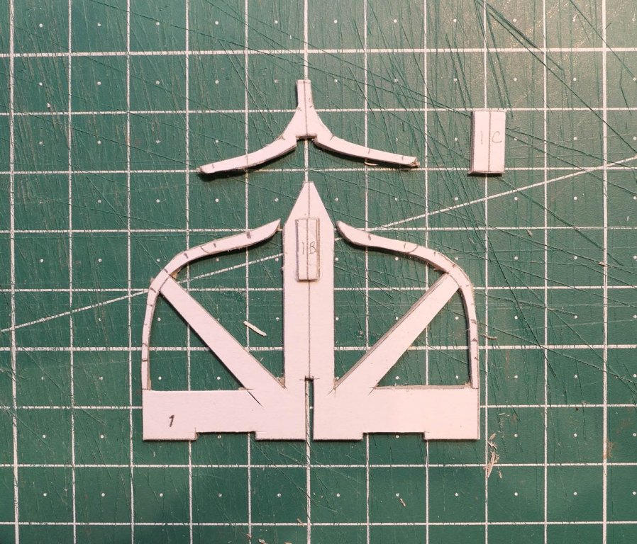
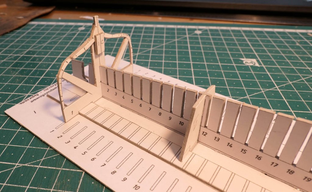
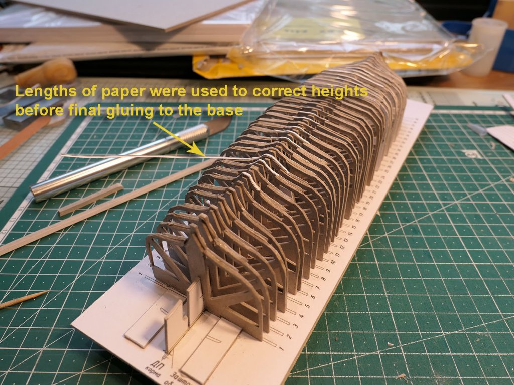
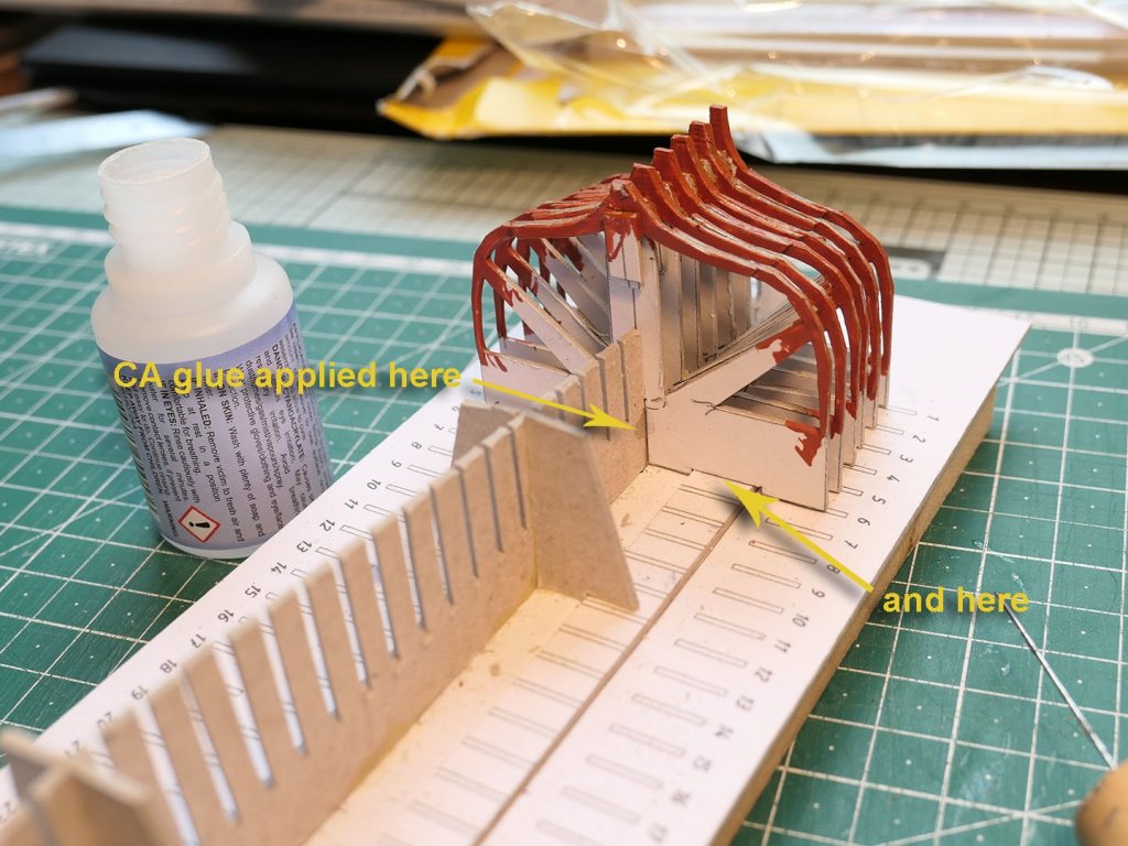
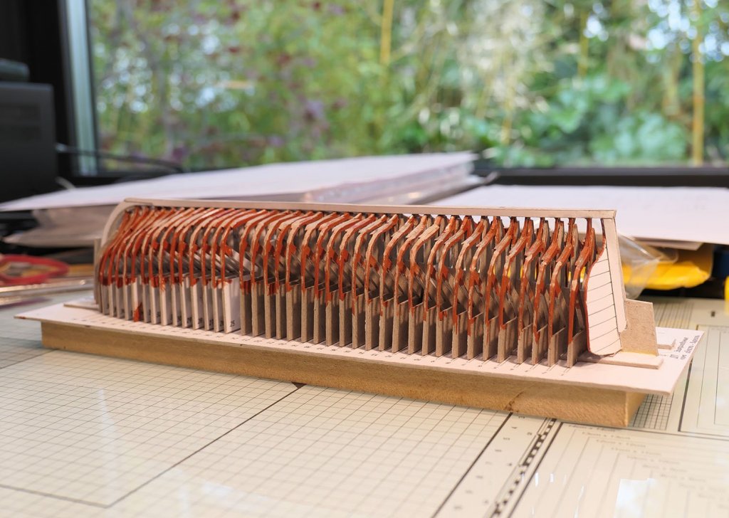
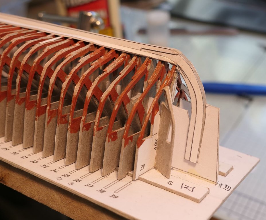
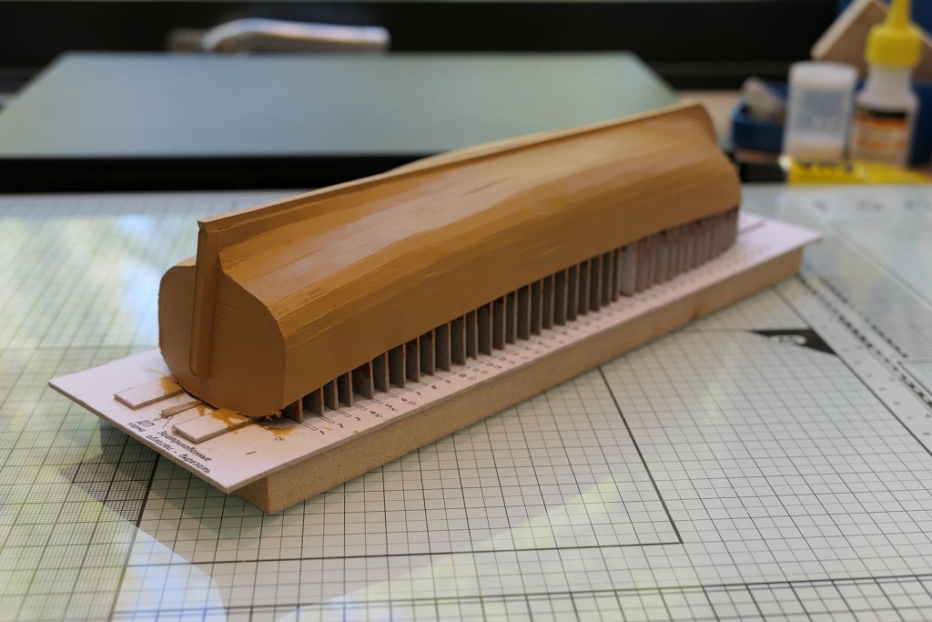
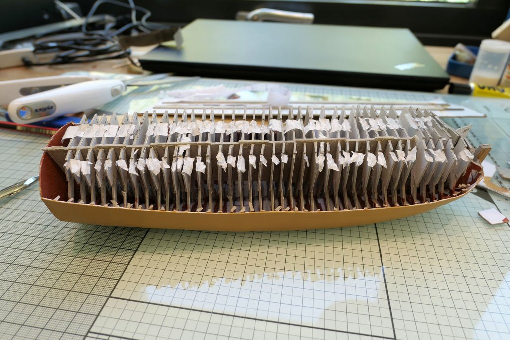
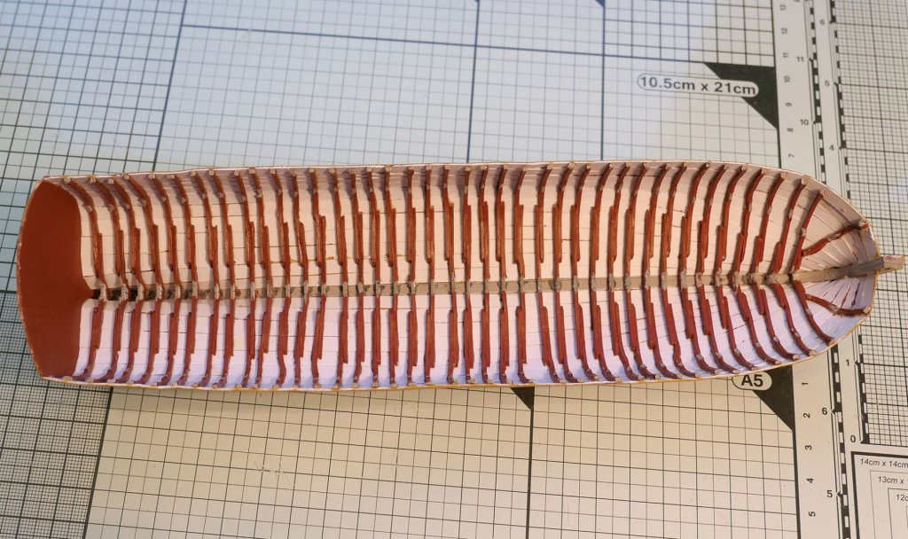
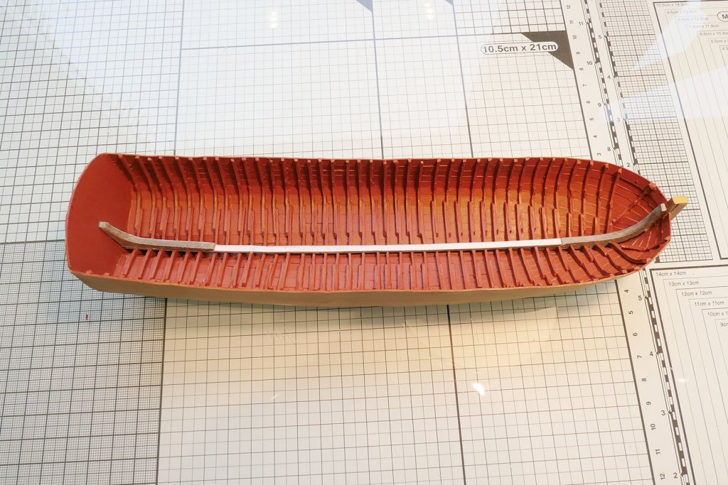
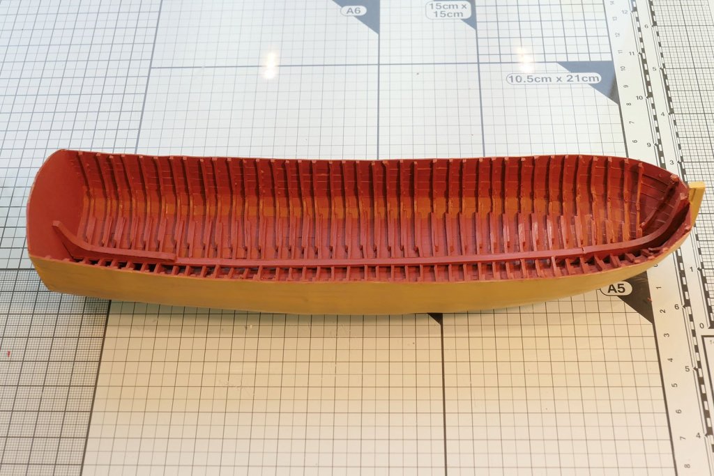
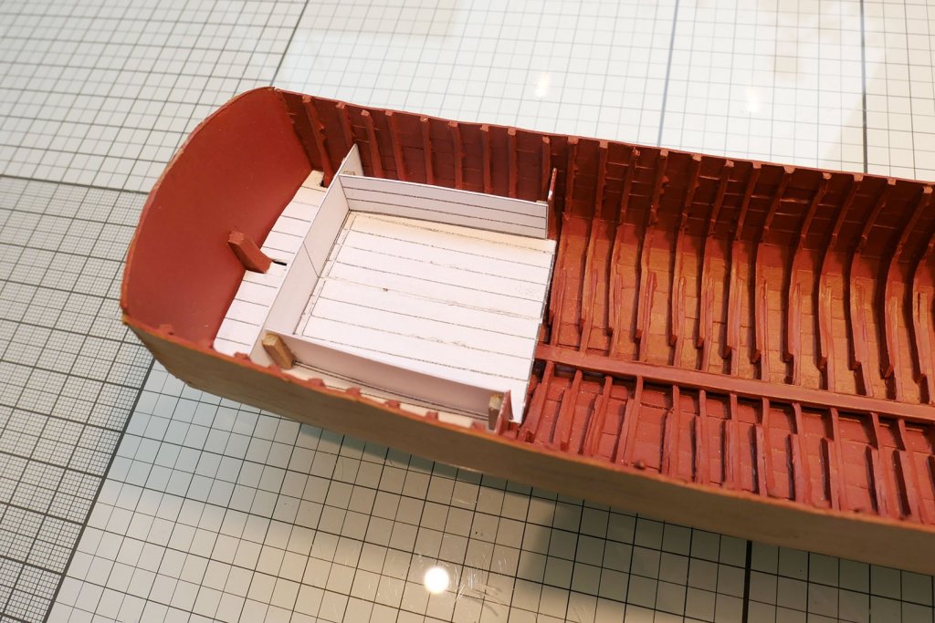
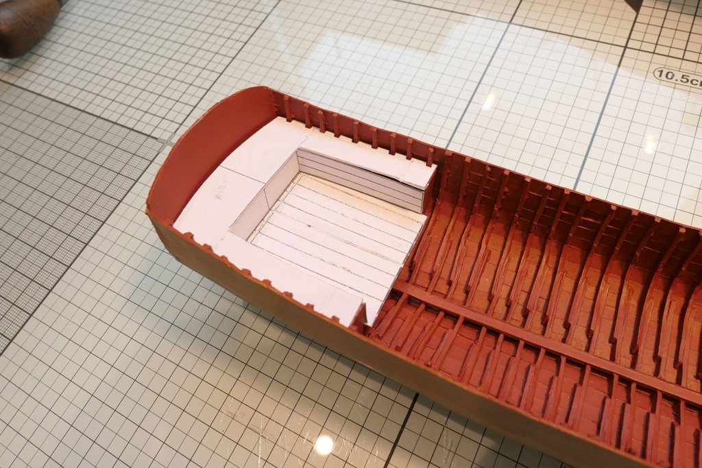
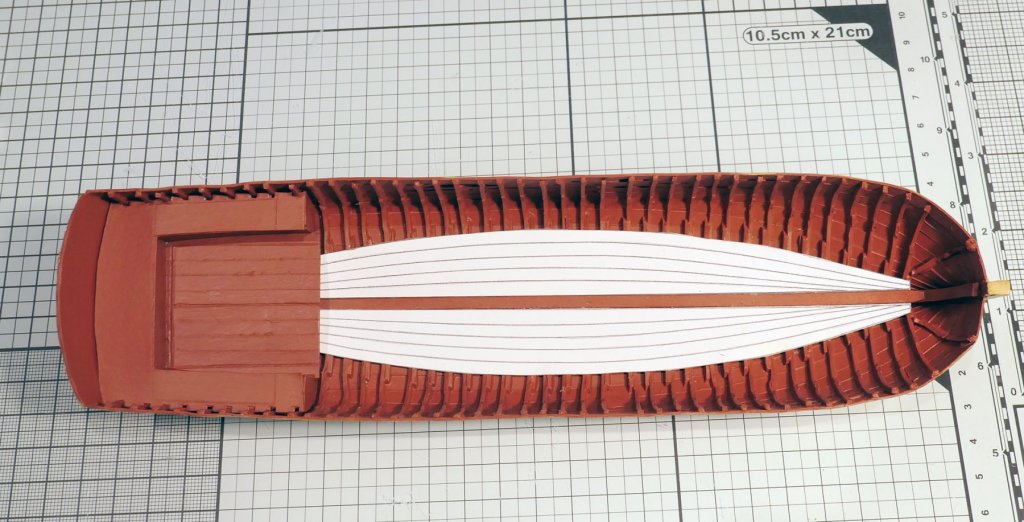
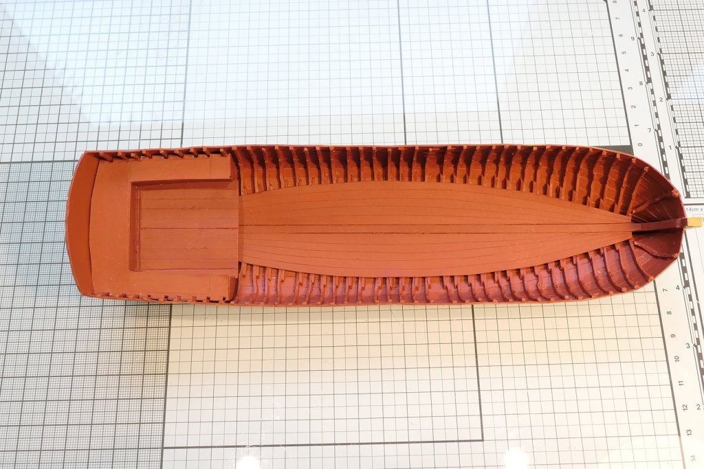
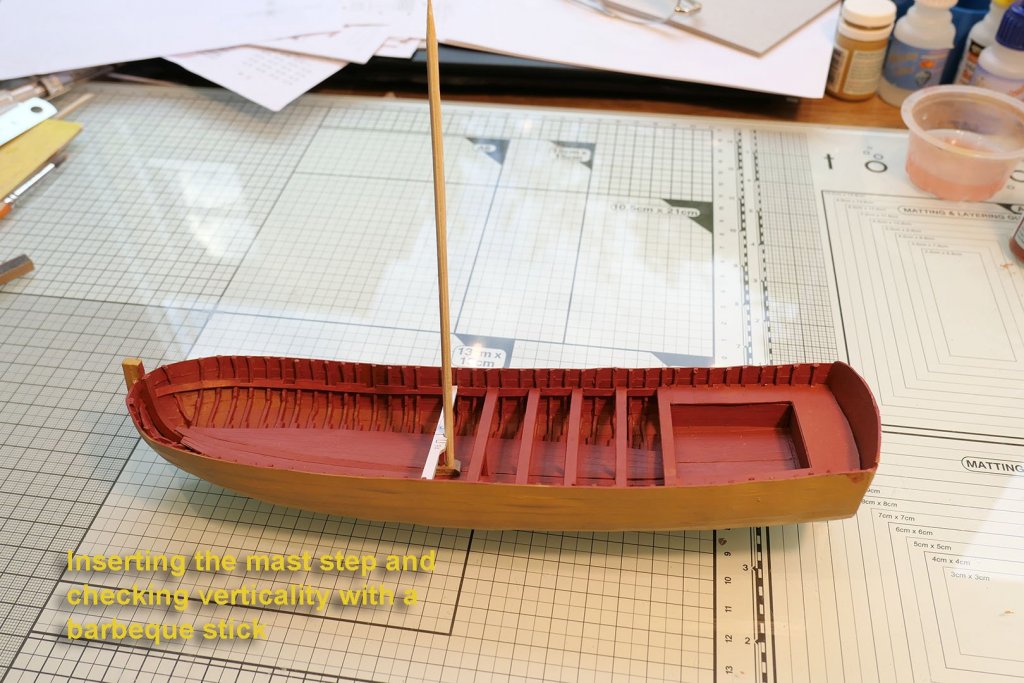
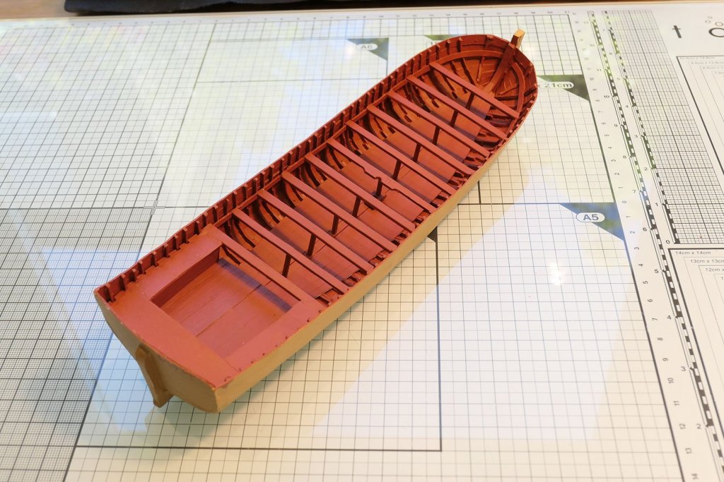
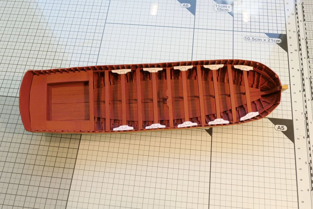
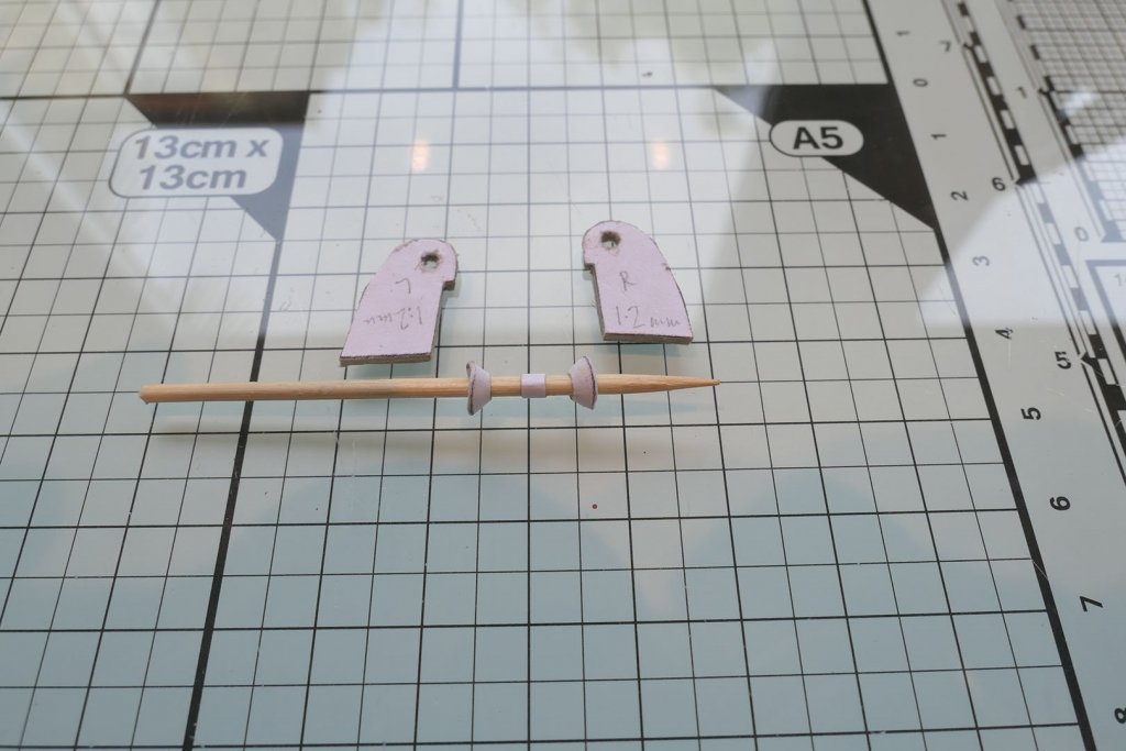
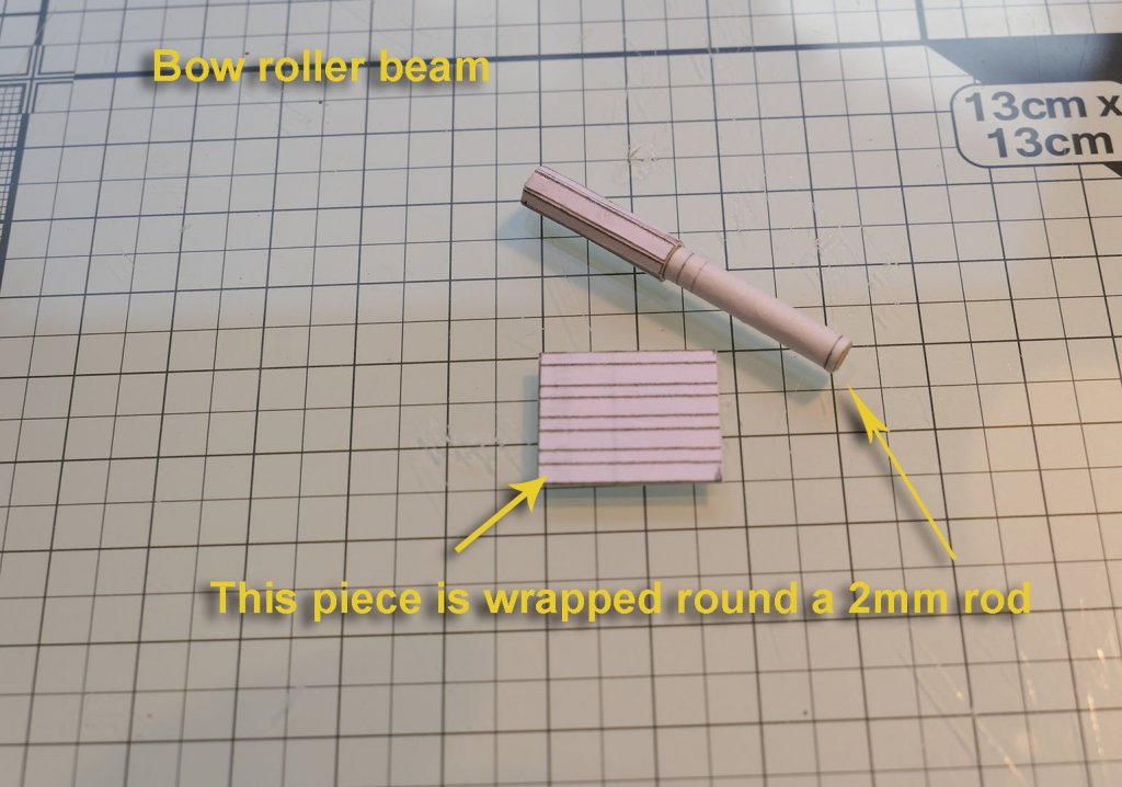
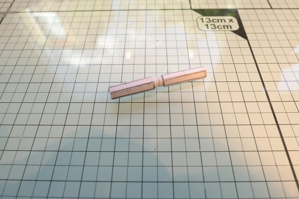
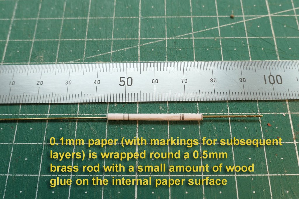
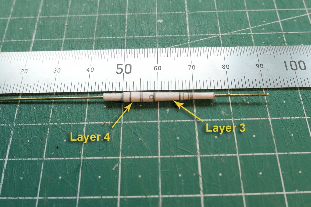
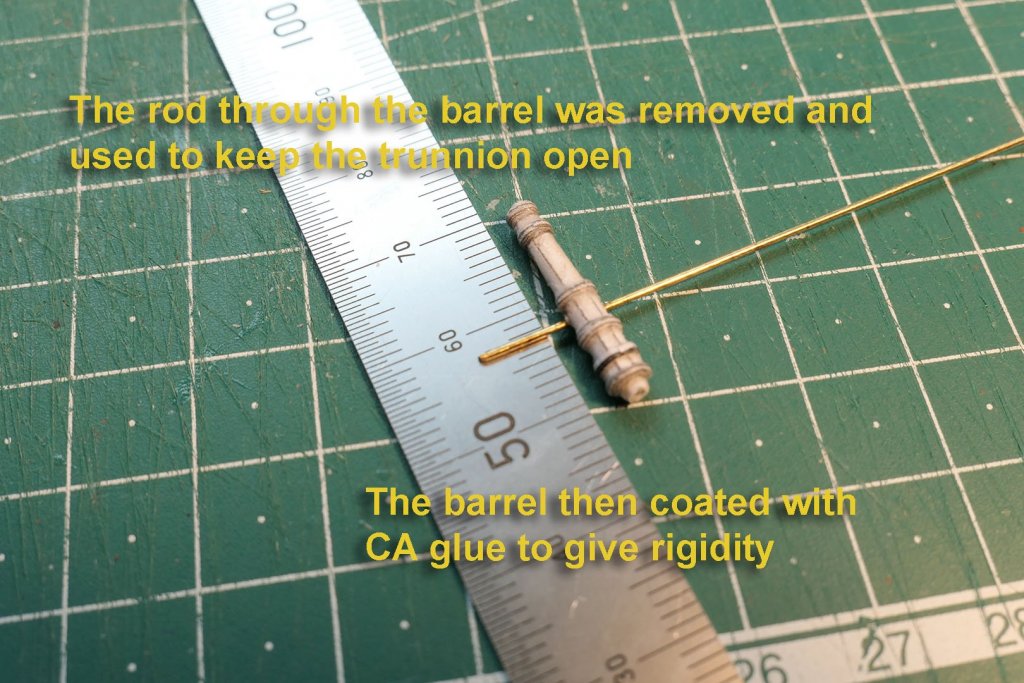
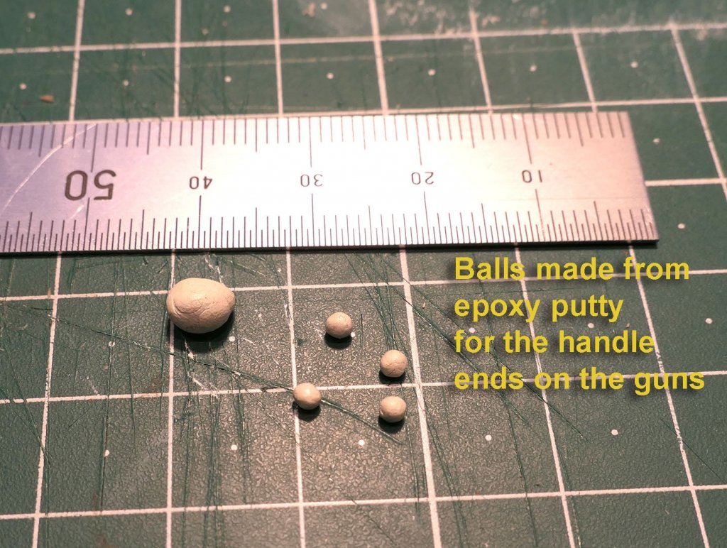
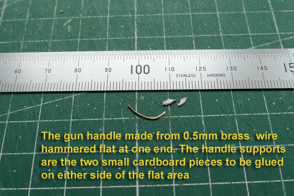
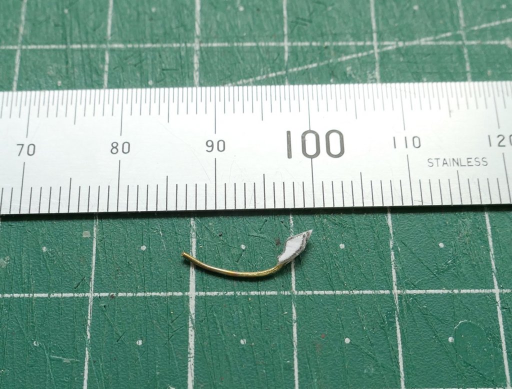
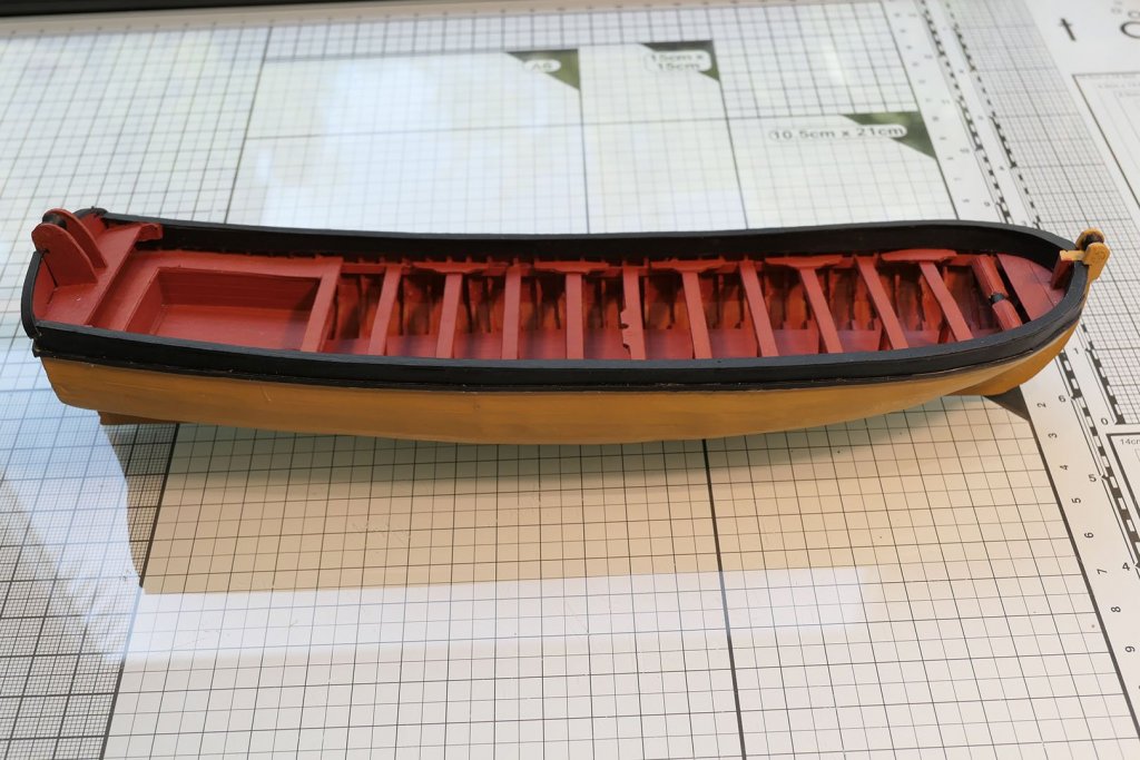
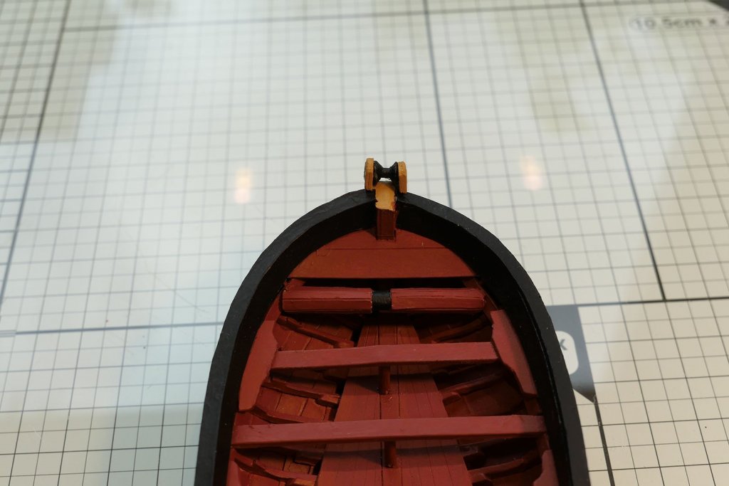
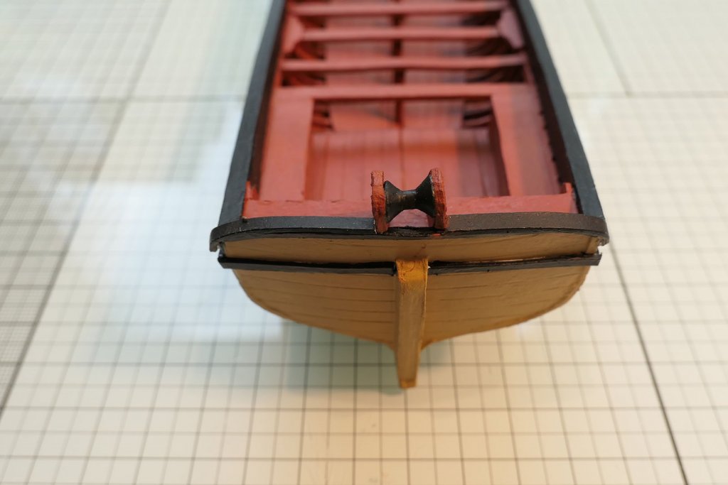
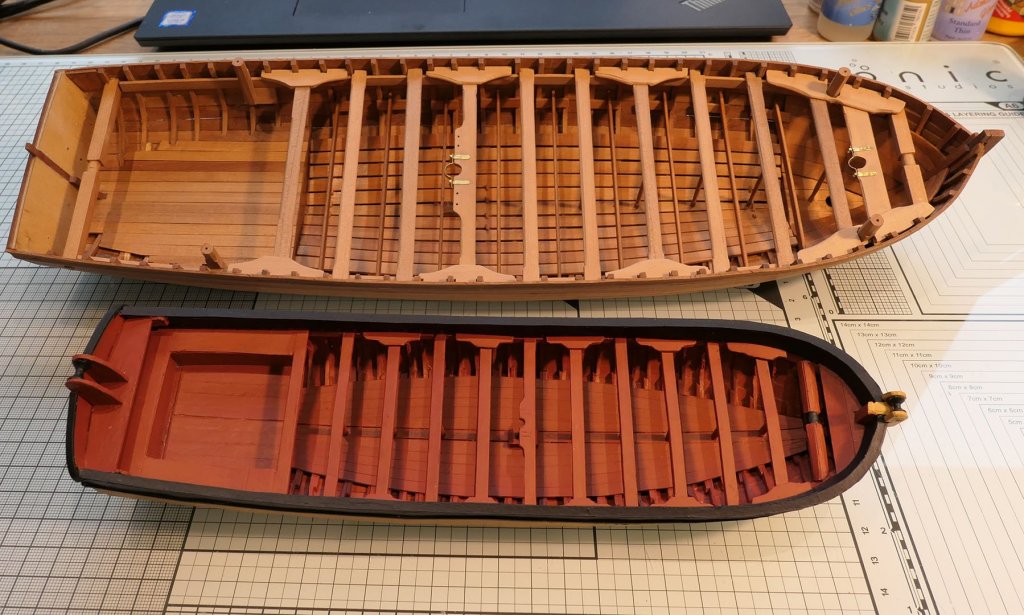
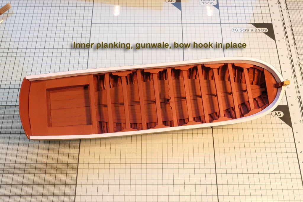
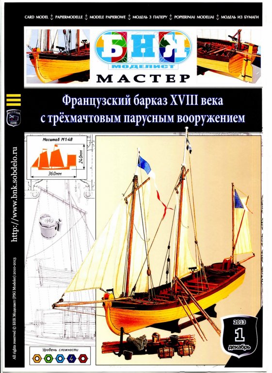
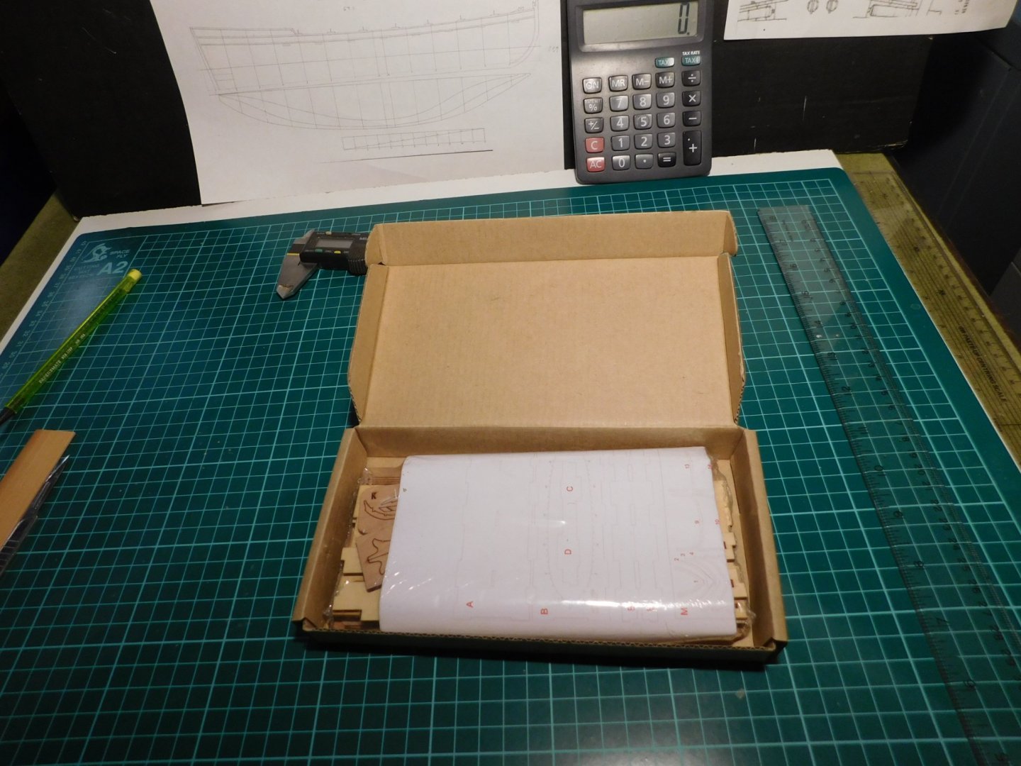
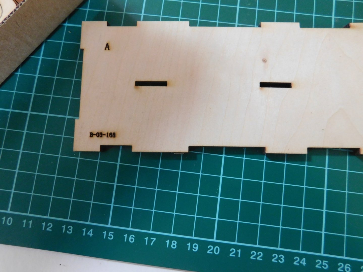
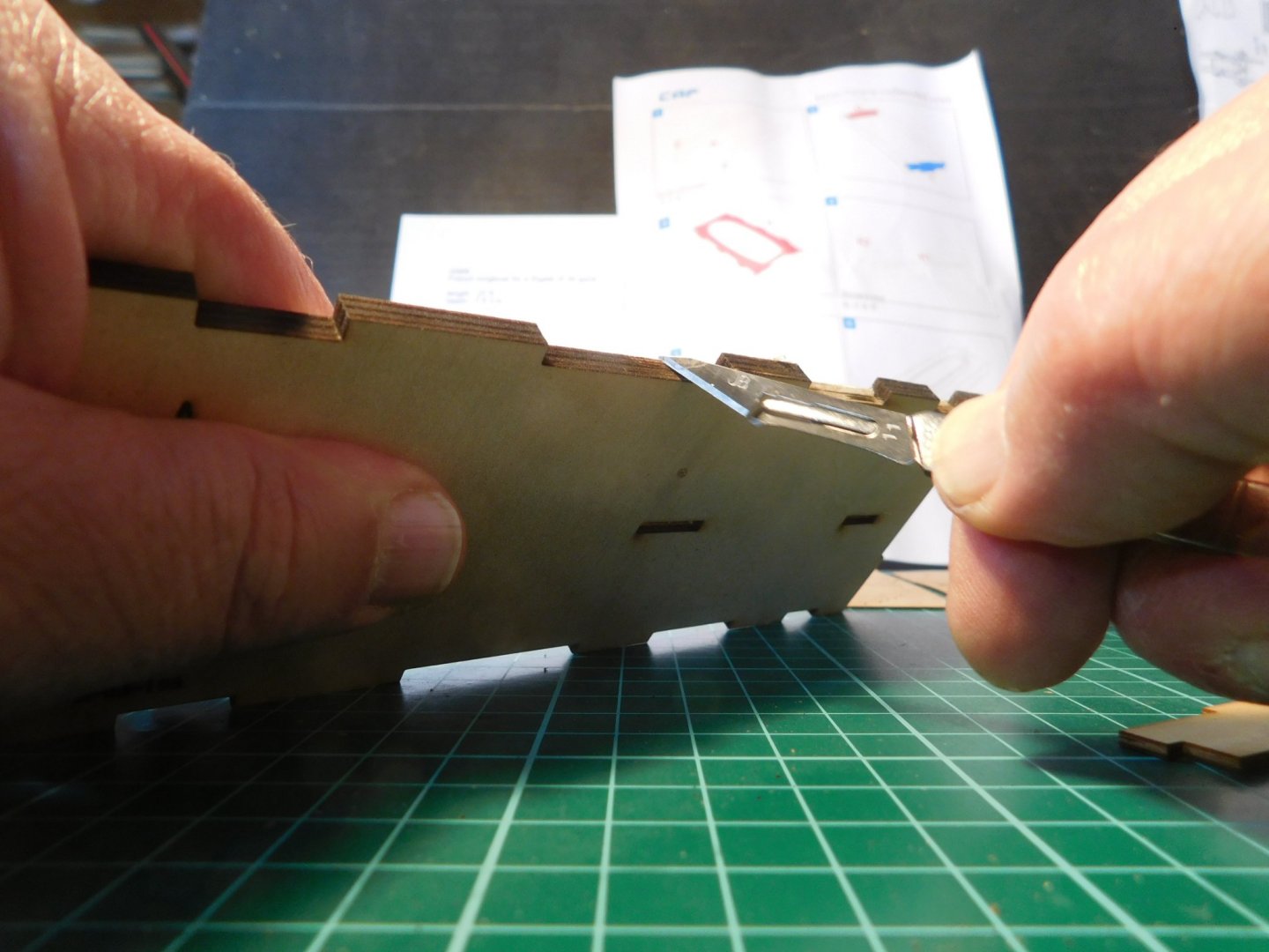
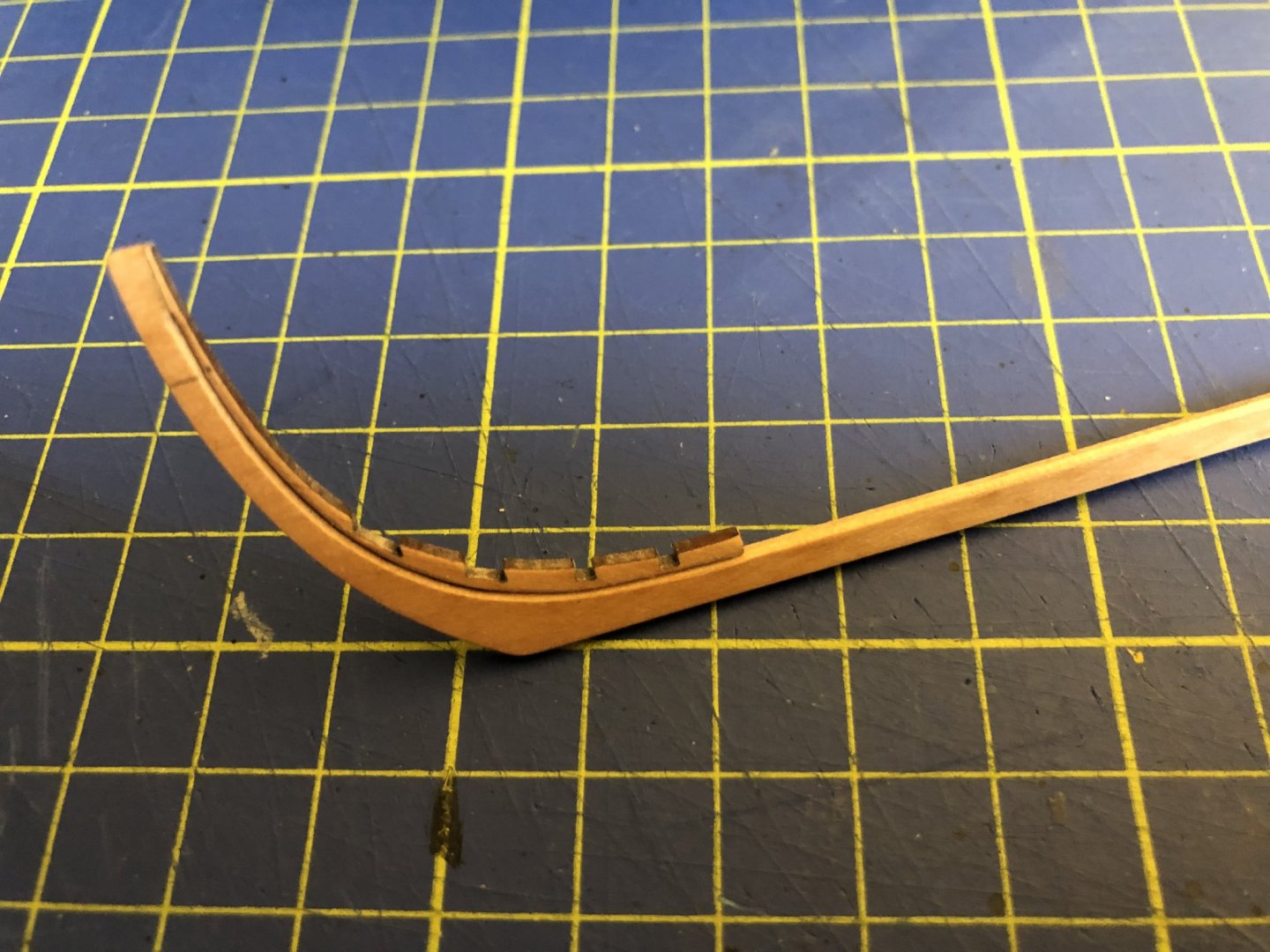
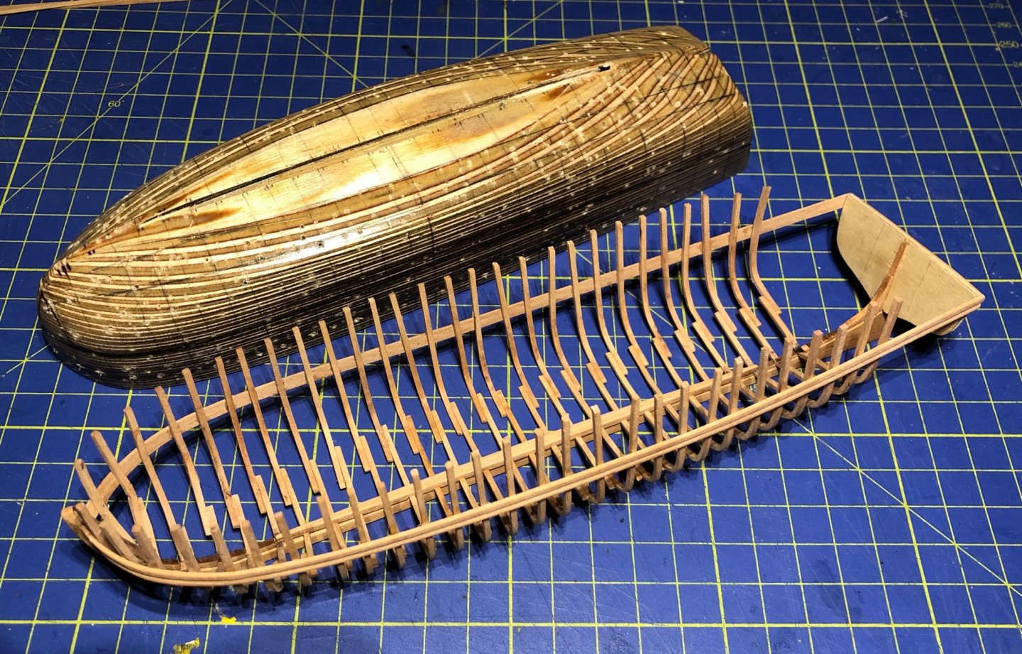
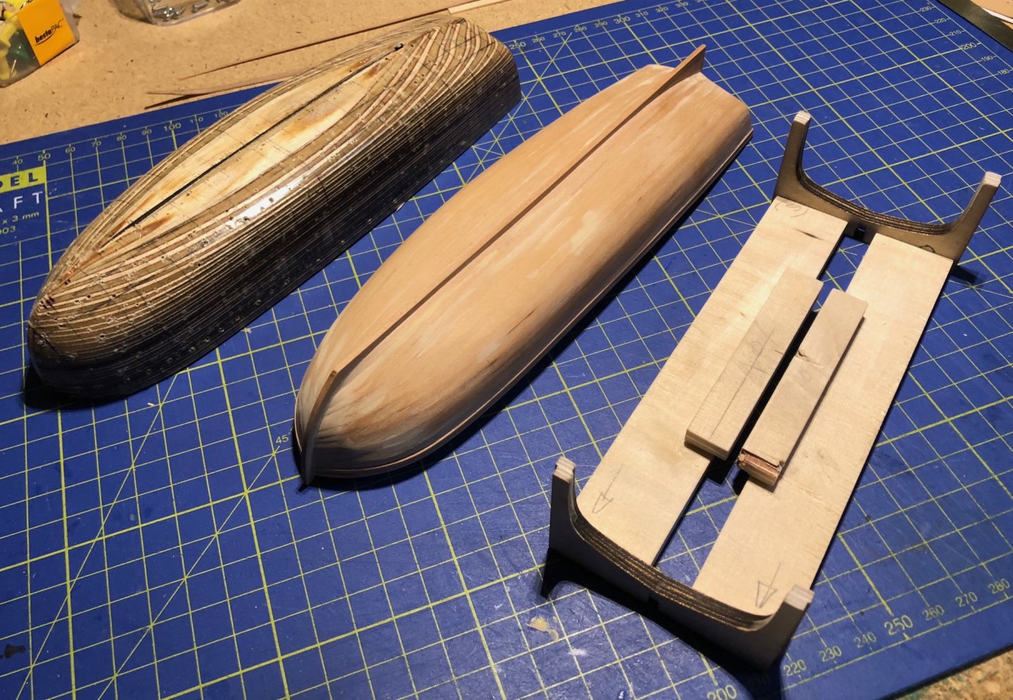
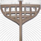
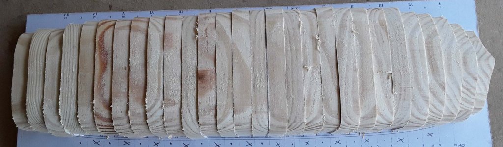
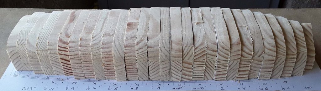
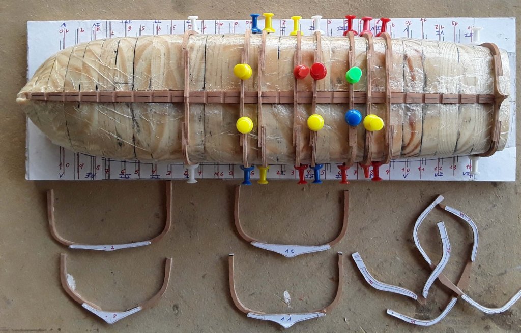
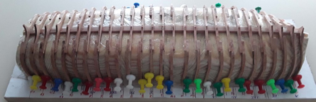
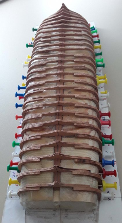
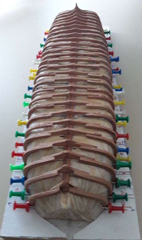
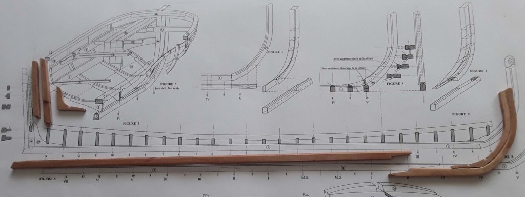
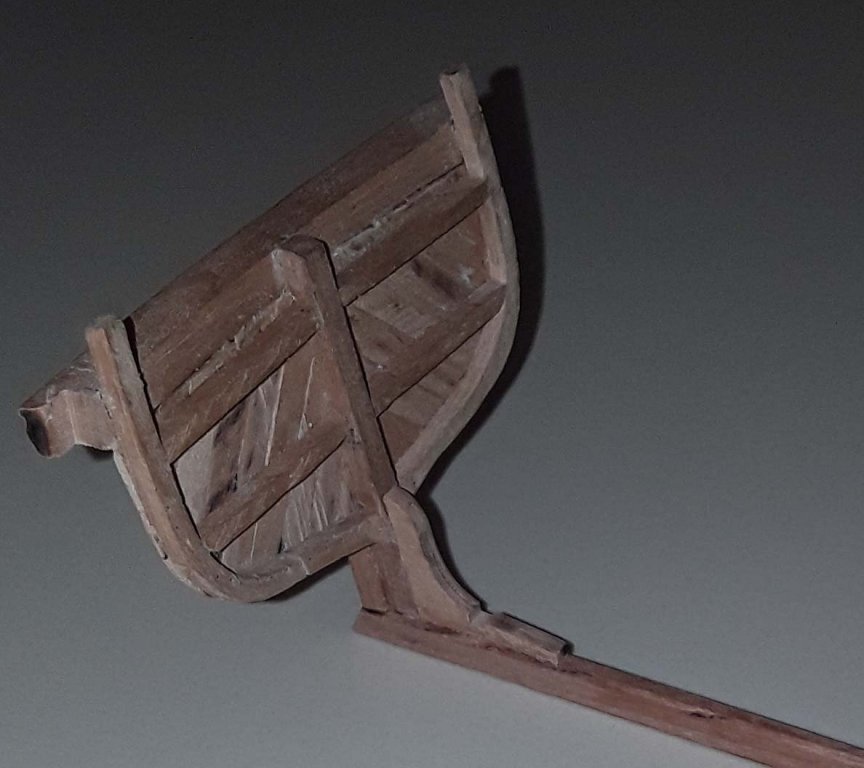
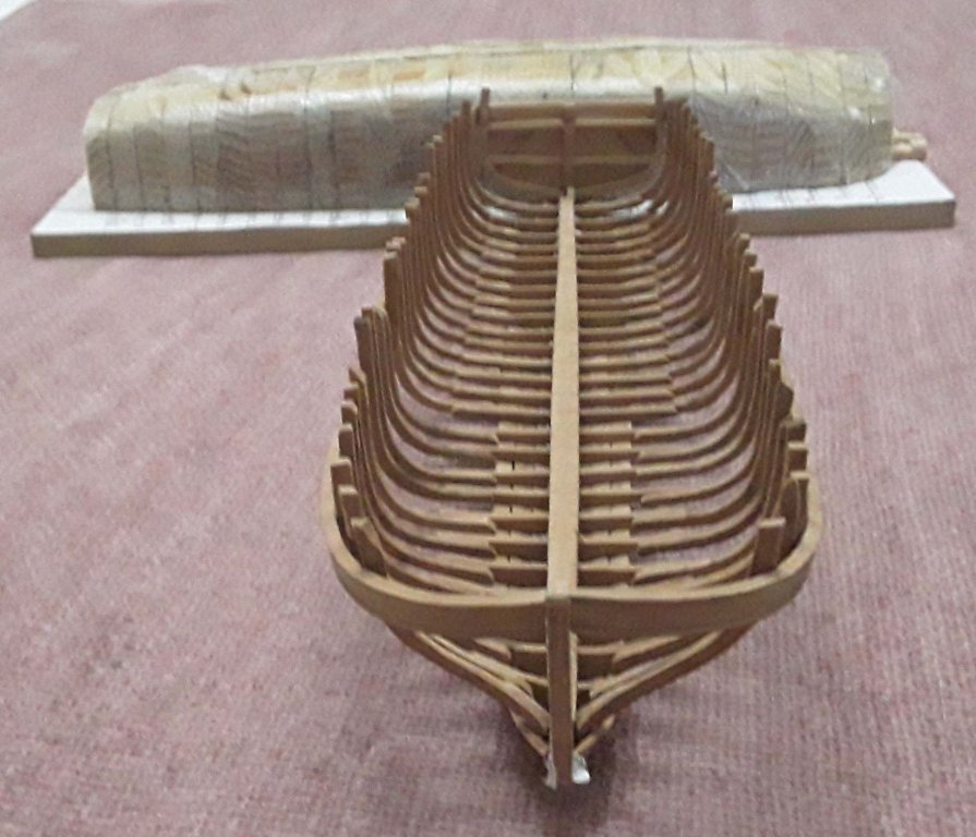
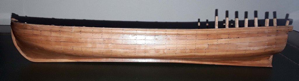
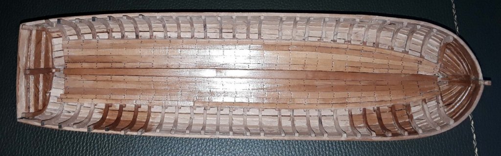
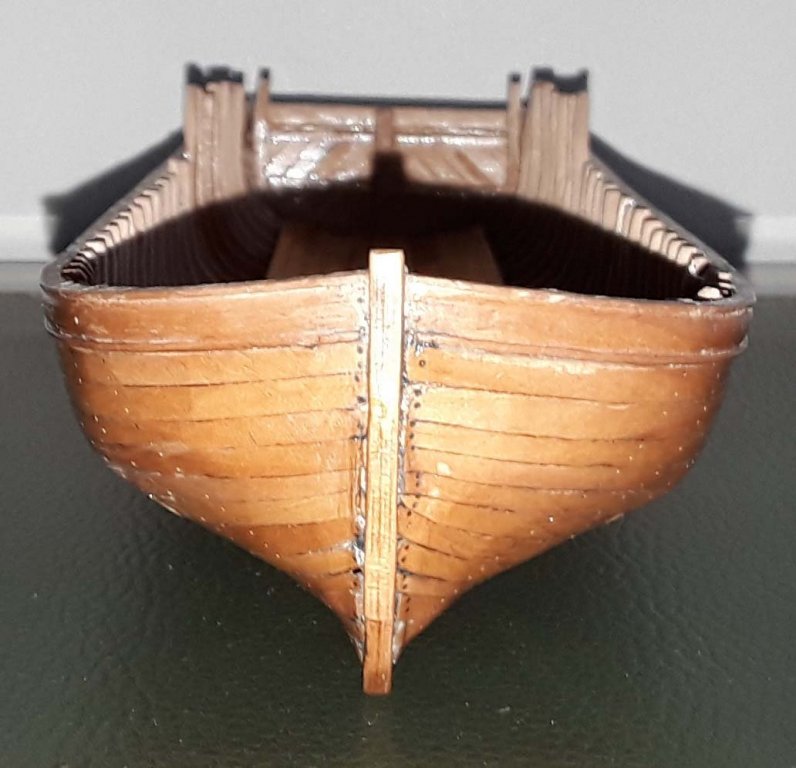
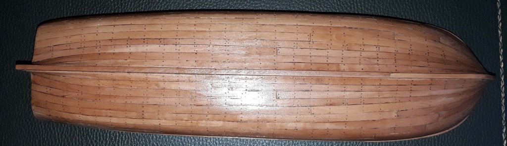
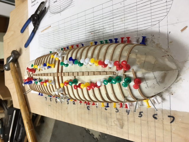
 I bought this kit after seeing completed builds on this and other sites. It is a model designed by Daniel Dayn Vishnevsky-Karlskhagen and I was intrigued to see how a longboat with its small frames could be built from card. It uses the same principle as the wood kits for longboats: frames supported by an internal plate which is removed after the external planking has been applied to the frames. The kit is low cost (I spent about €25 which included postage from Russia to the UK) and has excellent instructions. The only problem is that the instructions and guide are all in Russian (albeit with very good and useful illustrations), so I had to work hard using a variety of sources to translate it all into English. See my post on Russian translation and the resources used at and previously in my Chaloupe Armée build. For those who buy the kit I will be very willing to send them the translations of the instructions with the parts list. I have done the translations as a table with the original Russian in the left column and English in the right-hand column. I also have made a table or dictionary of Russian nautical terms used in the guide which goes with the parts list. I think you can only buy the kit from the author, whose email address is bureau.k68@gmail.com. You can see his full build of the original on the Russian forum at http://only-paper.ru/forum/85-12867-1, and you can see his discussion about it (in English) on the papermodelers forum at http://www.papermodelers.com/forum/ships-watercraft/27125-french-longboat-xviii-cen-most-large-pinnace-tree-masts-sails.html?highlight=planking . Because my interest was mainly in the method of construction, but also because I was prevented from continuing with my build of the Chaloupe by recuperation from surgery, I only built this model as far as completion of the basic boat without any masts or additions such as anchors and cleats. My main purpose in providing this Review/Log is to bring the attention of a really interesting kit to others on this forum who are proficient in card modelling or who just wish to probe it (as I did). I would rate it as fairly tricky but very rewarding. What’s in the kit? In addition to the guide and parts list, the parts themselves are printed on standard A4 photocopy paper. There are several sheets of 0.3mm card which can be multiplied to provide various thicknesses. The list of parts also details how thick each part should be. An interesting aspect of this kit is that the card comes in three colours: white, yellow ochre and red ochre. This is to allow you to make the model with a minimum of painting. A really nice feature of the kit is that plans are also provided for you to make all the masts, yards and fittings as well as accoutrements such as barrels, buckets, cleats, hooks, belaying pins and oars. A full rigging and sail plan is included, with directions for the varying rope thicknesses. Finally, the author has a practicum with colour photos which he will send you (in Russian). The base The first thing to make was the base. This is really sturdy, and, as with all the pieces, requires accurate cutting out so that the frames, when inserted, fit exactly. You’ll note in the photo the Swann Morton scalpel with a no 26 blade I use which I keep sharp by stropping after every few cuts. You can get the idea of the frame assembly with the following diagram: It is clear that you have to be very careful with where you place the glue if you want to remove the shell from the assembly later. But you can see that it does replicate very neatly the framing structure of the boat with floors and futtocks. You can see the assembly sequence in the photos below. The guide points to the fact that all but three of the 40 frames have the same height, so it is important to have a method of making sure that the height is correct. I built a small jig to build most of the frames, but later on just used a slide rule to check the heights. Despite all this my measurements were frequently incorrect and I had to adjust several frames by filing or gluing on various thicknesses of 0.1mm paper. Because the frames were made from grey/brown card, the instruction was to paint them with red ochre. This I did, but regretted because (a) I painted it on too thickly and (b) later on it interfered with the gluing. You can also see how the paint covered the holding frame – which I then had to separate from the floor with a scalpel in order to ensure I could remove the frames from the mould. Actually, after finishing the entire 40 frames, I was so dissatisfied that I made the model again, base and all, to this stage again, but being more careful with glue and paint. I don’t have photos of the second frame and mould, so you’ll have to make do with the photos of the first attempt! Stem, keel and stern timbers were then cut from 3mm card, glued and the assembly held in place with rubber bands. Planking I then laid the planks. I could have used the coloured card supplied in the kit, but I elected to use my own card which I then painted with yellow ochre. The spiled planks were beautifully accurate as printed, so I did not have to make any further adjustments when cutting from the plans. As you see, the big problem for me was laying the planks so that they would be completely flat. Mine turned out in a rather wavy fashion! Once the planking is complete, the shell with its frames can be cut from the mould. First there’s the rough cut using curved scissors to cut around the edges at the level of the rubbing strake and then to cut the areas attached to the base floor. The frame supports can now be cut away. Because I had used my own card, I had to paint the interior with red ochre. Finishing the hull The keelson, stemson and sternson are then put in place. The counter and timbers for the cuddy can now be added. With the cuddy finished, the main floorboards can be inserted. The thwart stringers are placed. The thwarts were made from 3mm card, and the supports made from 2mm cocktail sticks. The mainmast step was made from wood, using the plan in the guide. Now the thwart knees. The davit timbers and their roller are now constructed and assembled. The front davit with its roller were made in an identical way. The main remaining piece of the hull was the roller beam at the front. Swivel Guns Having done the main hull (without the swivel gun mounts, cleats, mast straps, belaying pins etc.) I thought that even though I wouldn’t arm the boat I would still see how cannon were made with paper alone. The instructions in this regard are excellent. I started with a simple roll of paper, marked with the positions for the subsequent layers of paper. Final result So, at its current stage, the model looks like this: In comparison with my ongoing 1:36 build of the Chaloupe Armée: I won’t be going any further with this build as from now on I will concentrate on finishing my build of the Chaloupe Armée. It is just possible that at some future date I will continue, but don’t hold your breath! The purpose of this review/log was mainly to bring the potential of this very nice model to the forum, and especially those who wish to explore card modelling – which, as you can see, offers up its own delights, techniques, thought processes and problems. Tony


-
 Hello, First post here in this group and can I say thank you for accepting me into this group. It seems a wonderful resource for anyone interested in model ships regardless of their experience level. So this is my first foray into wood, I have been over on "The Dark side" making plastic models of all different subjects. I purchased HMS Endeavour's Longboat quite a few years ago and it has been on the "maybe next model" list for a while. So I suppose it's time has come. As with a lot of other comments I have read on this site, the key seems to be slow and steady (so please be patient with me as I am a naturally slow modeler) and really check fit and alignment before gluing . One thing I would mention is the instructions that come with this particular model leave much to be... shall we say "deduced". I have put together the frame and all seems in alignment and progressing well.
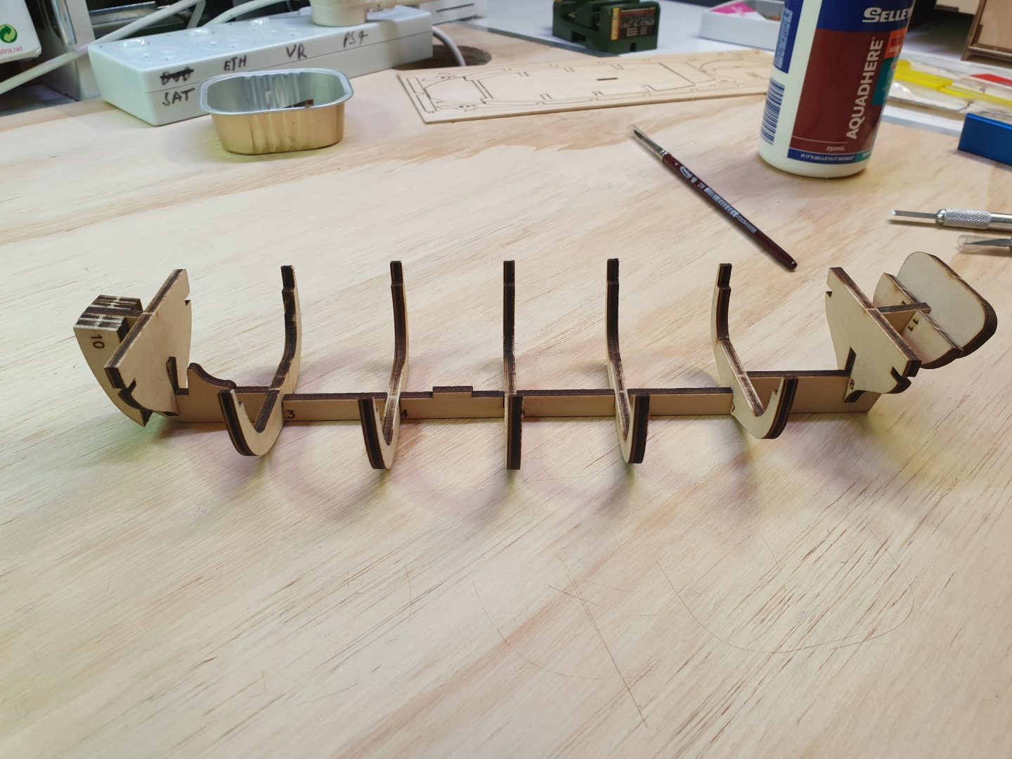
- 4 replies
-
- 2
-
-
- Longboat
- First Build
- (and 1 more)
-
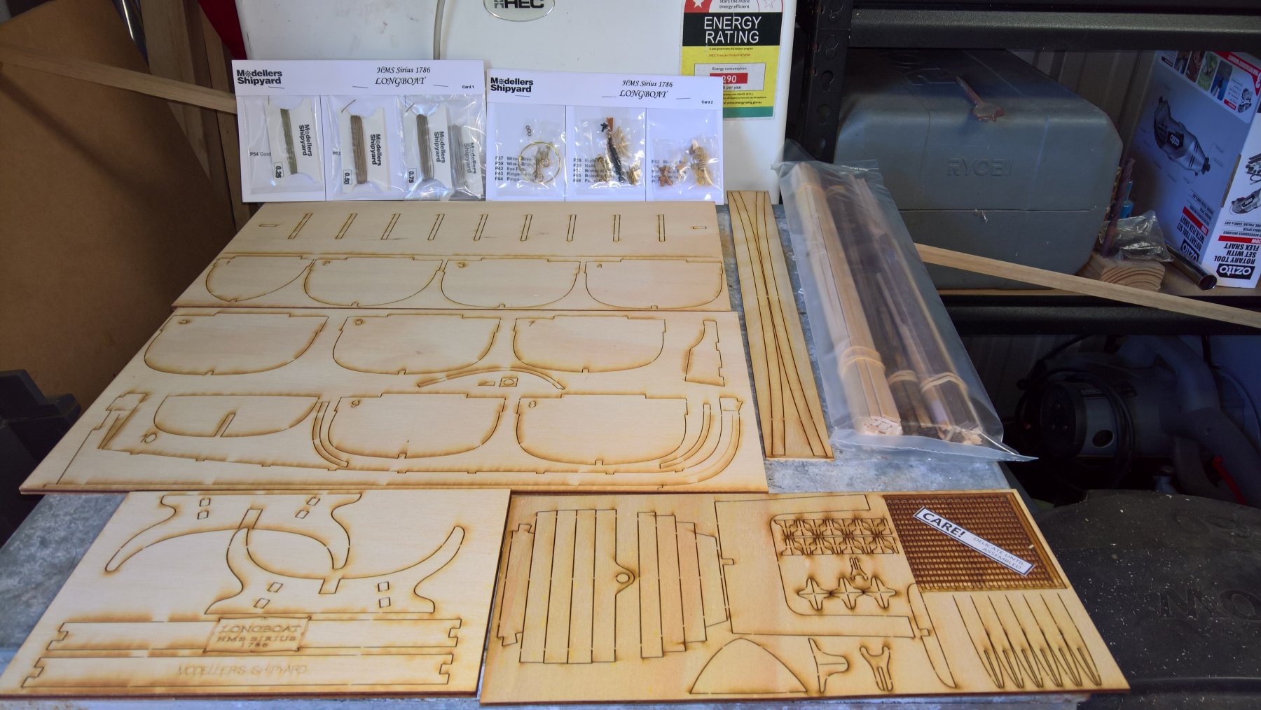
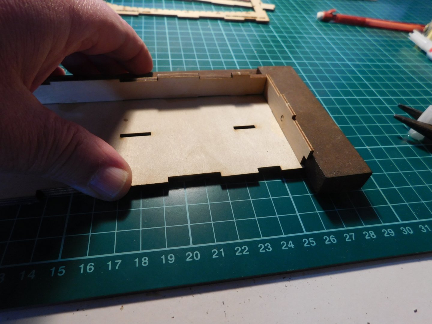
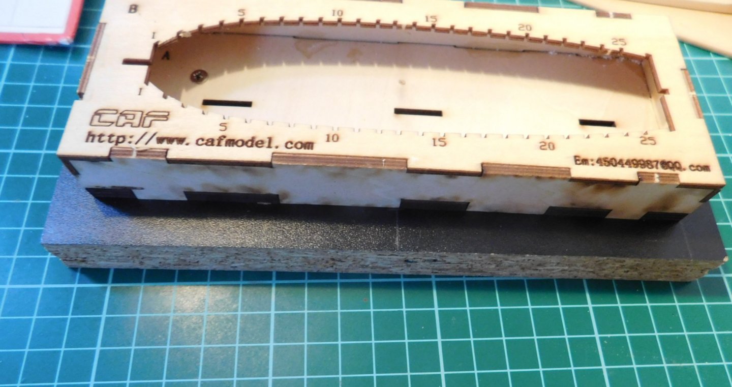
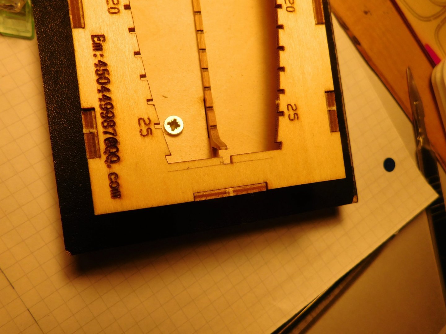
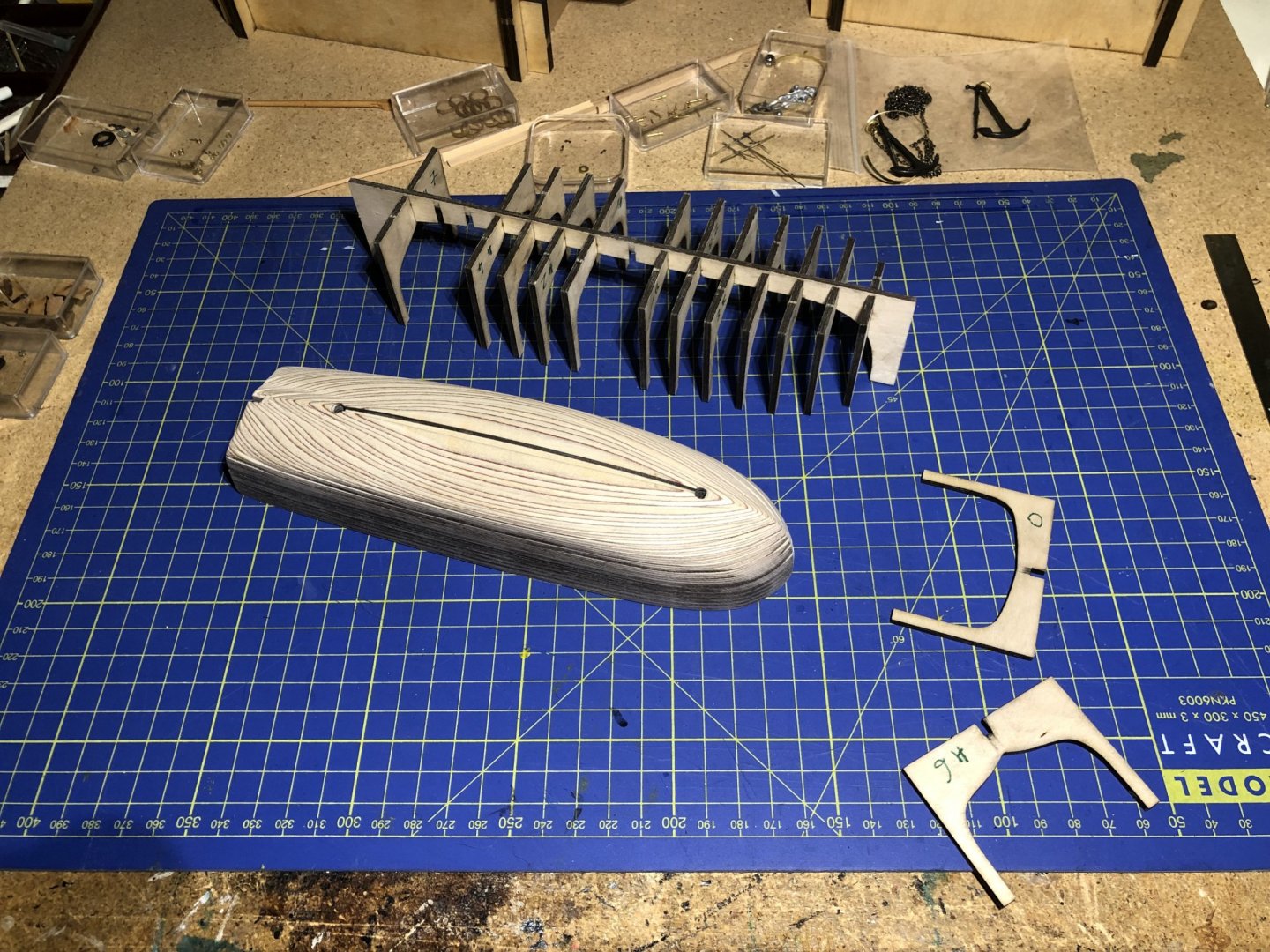
 This is a build log for the CAFMODEL longboat. Although I will dwell in detail on the features and instructions of the kit, it is not an official kit review as this is my first ever attempt at building a laser cut kit and it would clearly be wrong for my comments and observations to carry the weight of an experienced reviewer/builder. Having said that, the kit instructions show where parts go, not how to do it, and I believe anyone building this model will come across the same issues I encountered. Hence the level of detail in my log. After an exchange of emails with Tom at CAFMODEL I purchased this and two other kits. I found Tom very approachable and helpful. The kit: The CAFMODEL longboat (SB130 – 168) is a 1/48 scale French longboat based on Ancre sources. The subject is ostensibly a Louis XV era longboat but could equally represent a later craft. It is of laser cut cherry wood and plywood plus photoetched parts. There is also a piece of .8mm brass wire for some detail work. EDIT: it also has a small fret of photo-etched brass. The quality is good. The box contents are neatly packed. Instructions are graphic-style with a few notes (in English) and scale drawings. 2mm cherry, 1mm ply and .4mm cherry veneer make up the boat parts. The building cradle is 2mm ply. The laser cutting was precise and I found no areas where anything was over- or under-cut. The first thing was to understand the parts and what is required. This took me three cups of tea. Eventually I had a plan and, at least up to the time of writing, it has proved to be a good one. The critical process is the handling of the ribs and that will be explained when we come to them. To state the obvious, the building cradle is absolutely vital. Before assembly, I tested the fit of the different pieces of wood used for the stem and the ribs in their slots. To play safe I opened up the slots in the top piece for the ribs with a few strokes of 120 grit sandpaper wrapped around an old steel ruler. Next, I decided to screw the assembled cradle down to a block. This is not in the instructions but I anticipate this will help later. There are slots in the bottom piece of the cradle to hold the keel in place. When it is time to remove the keel assembly you push upwards through these slots to remove the skeleton. These slots will be covered so I drilled access holes in the bigger block before screwing the cradle down. Once screwed to block and checked, we’re off.


-
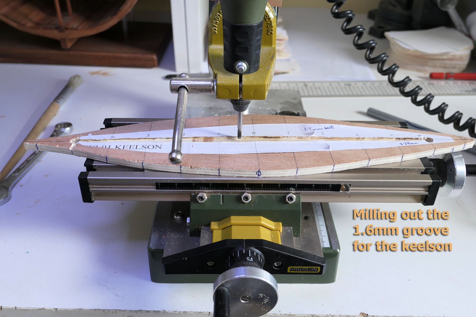
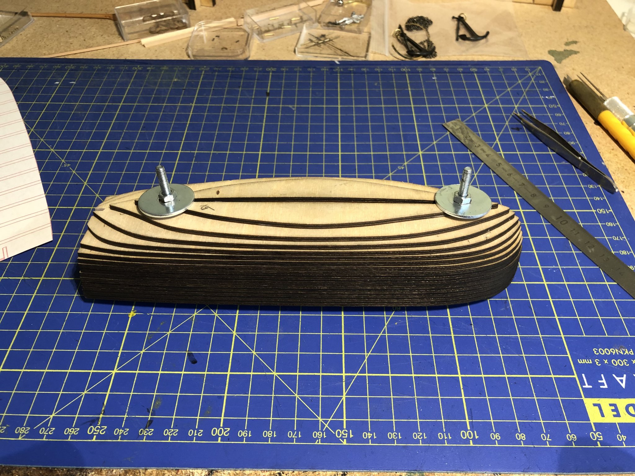
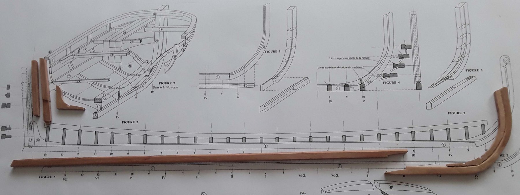
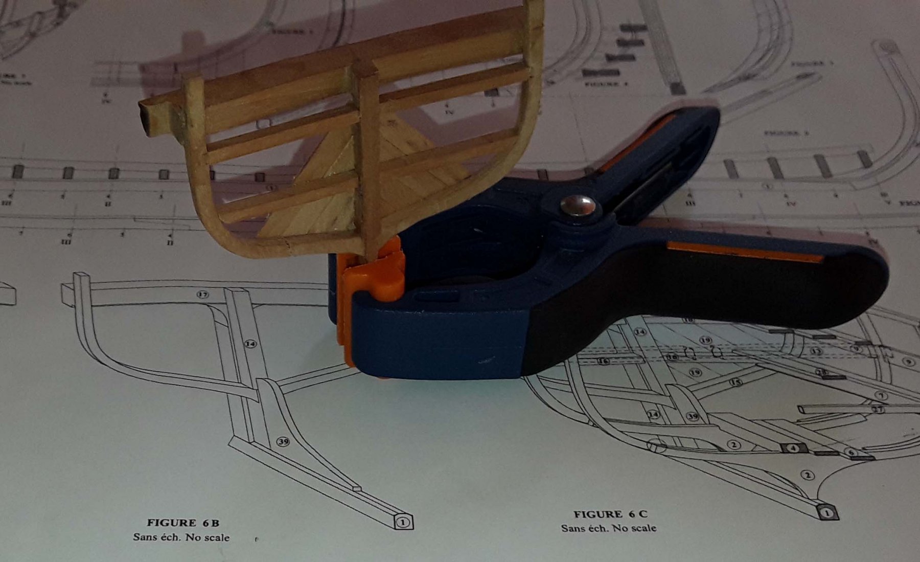
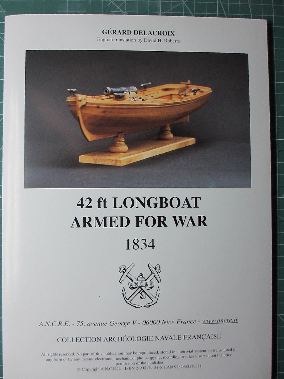
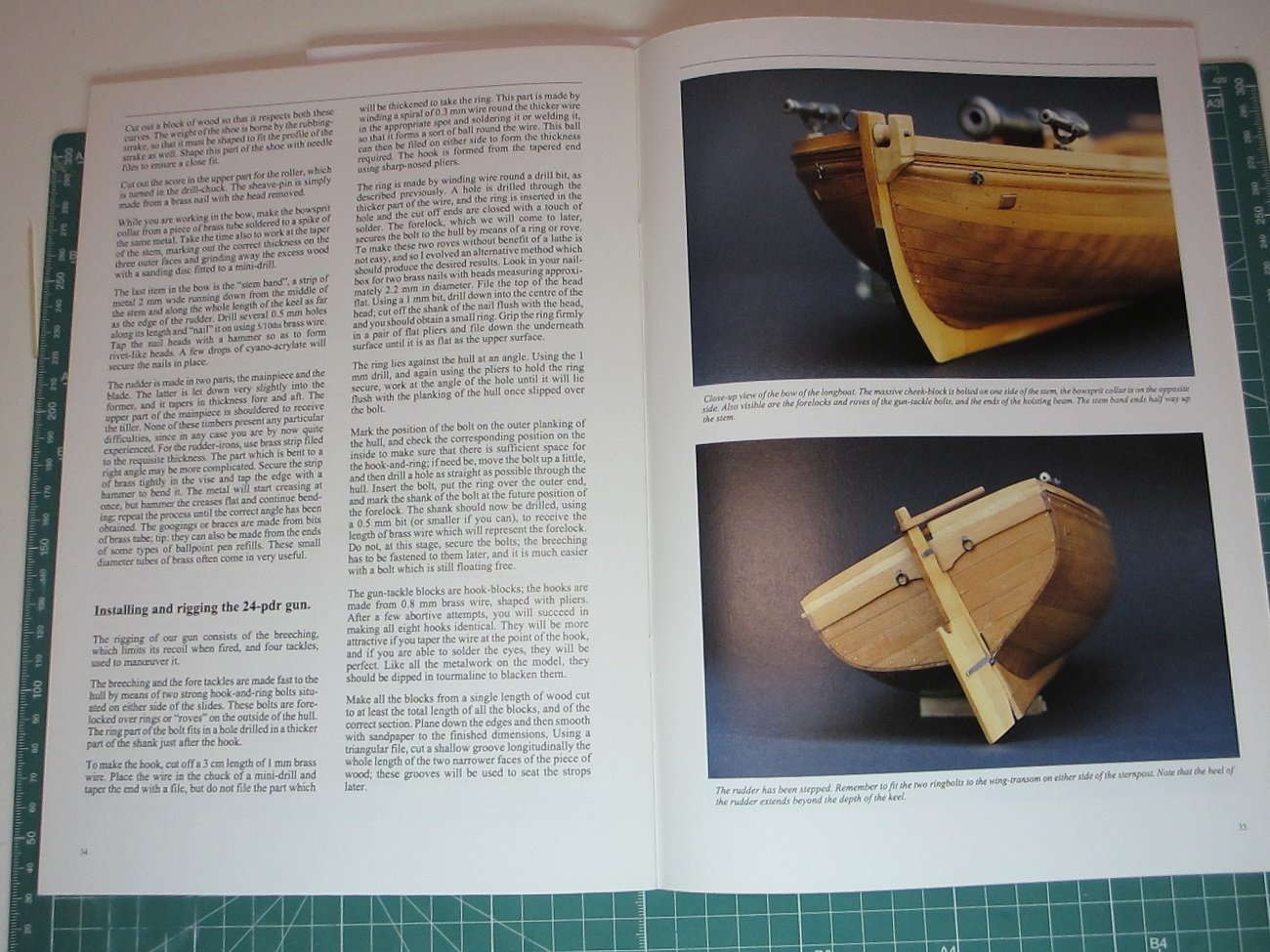
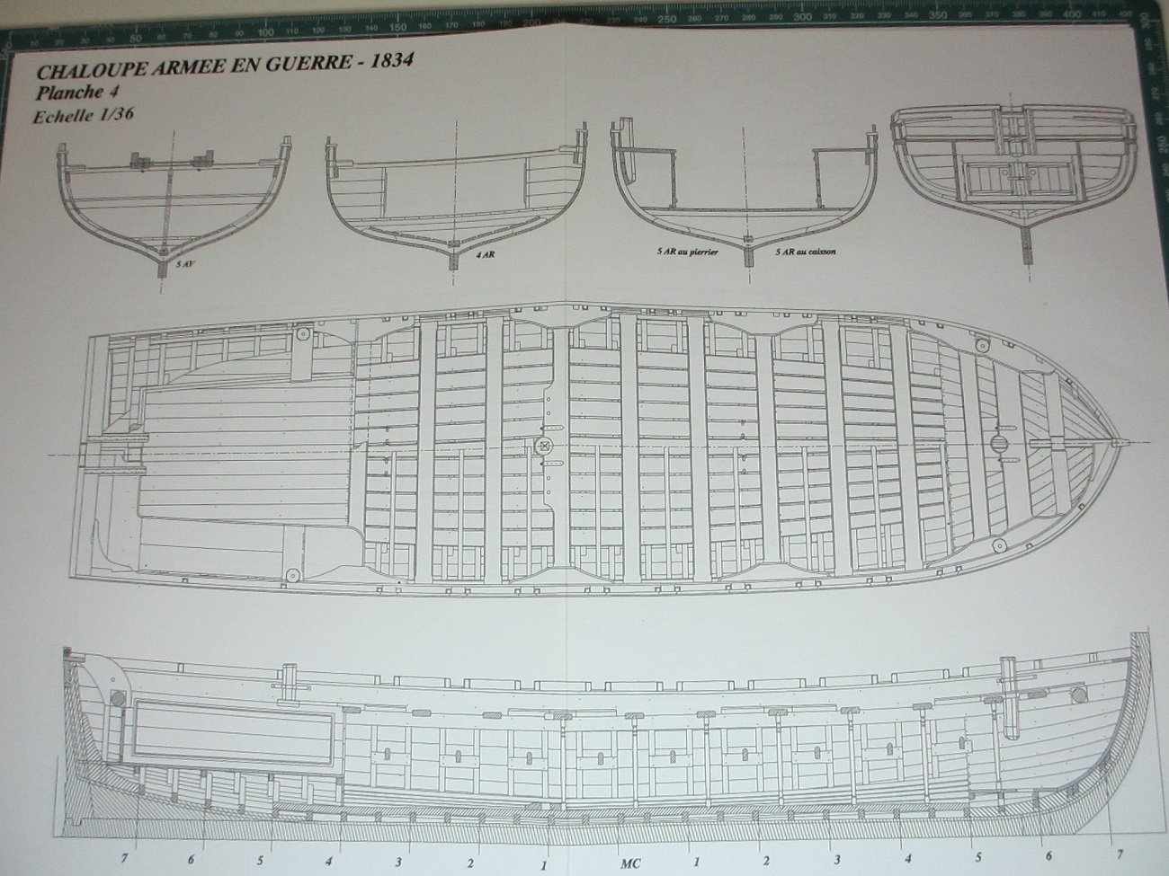
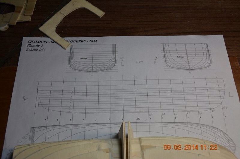
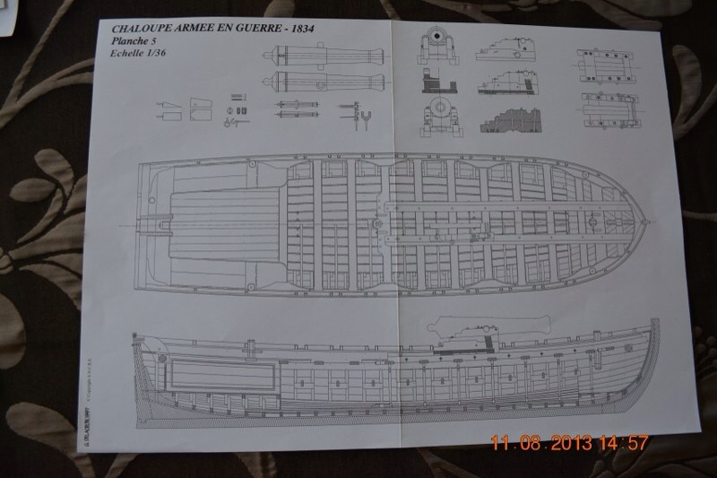
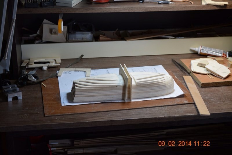
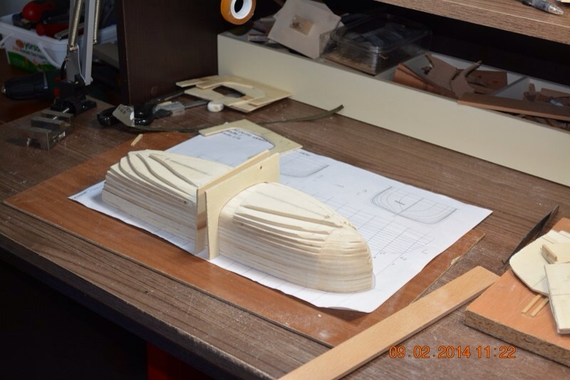
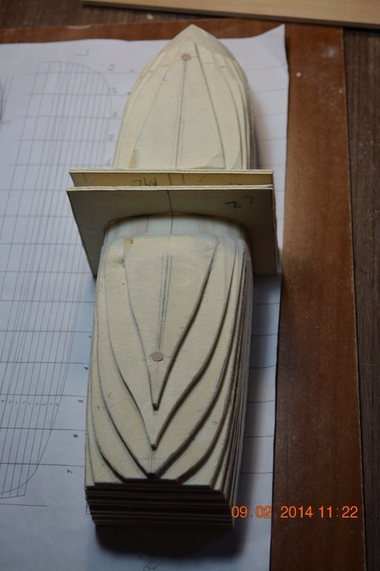
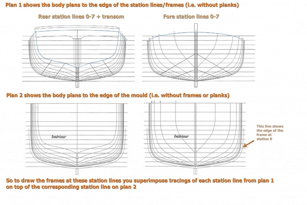
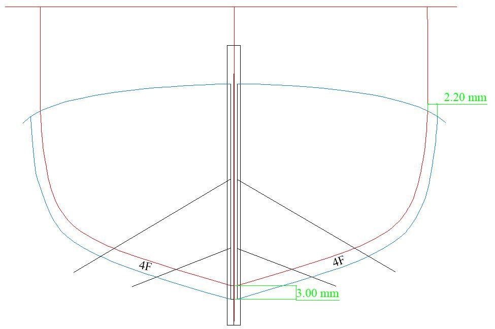
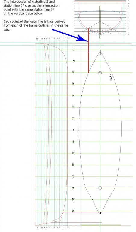
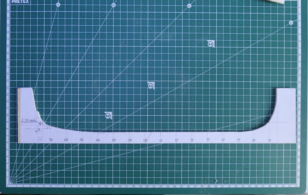
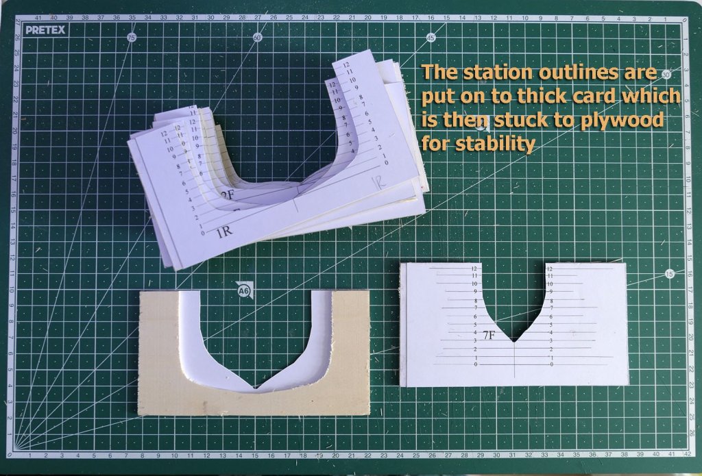
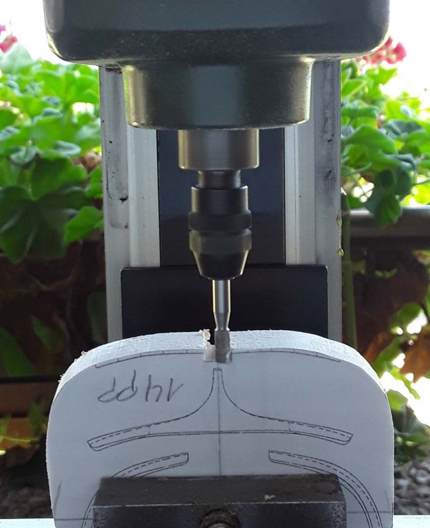
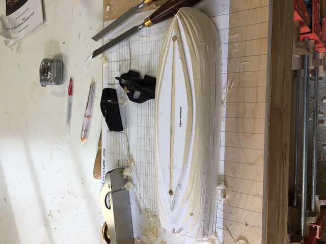
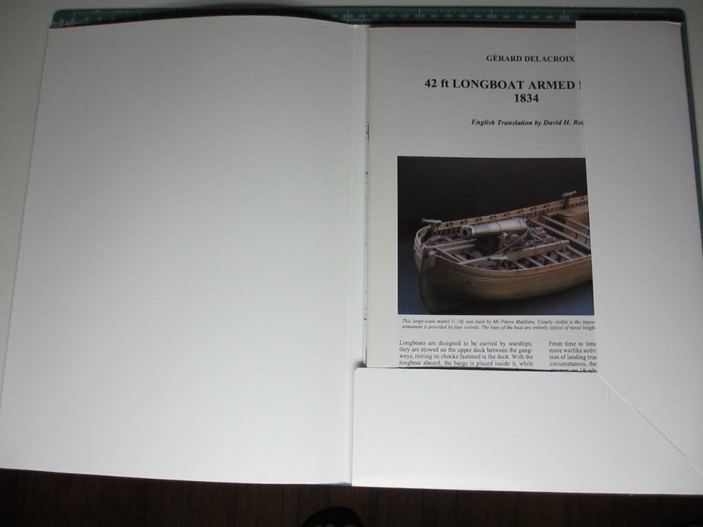
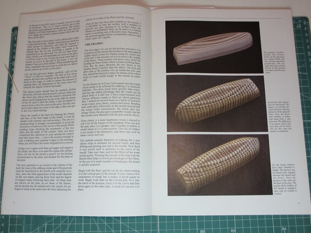
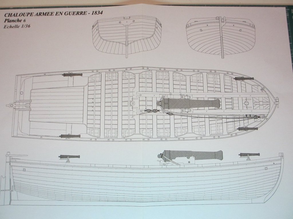
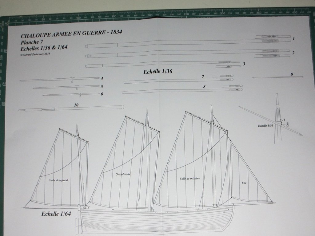
INTRODUCTION AND OTHER BUILDS In June 2017 I was considering what to build next. The main criterion was to keep learning but with a different type of boat and a different type of construction. I tinkered with the idea of La Jacinthe, Le Rochefort, and even thought of embarking on Ed Tosti’s plans for the Naiad. However I thought a logical next step would be to go for a longboat using a mould as construction type. So I started on Gérard Delacroix’ plans for the French armed longboat of 1834. The plans for this are available in several languages from Ancre at https://ancre.fr/en/monograph/31-monographie-de-la-chaloupe-armee-en-guerre-1834.html. As stated in the English translation of the introductory manual, the model is “based on a draught in the 1834 Atlas du Génie Maritime (Folio of the Corps of Naval Engineers). The longboat, at 42’8” long, is of imposing dimensions, being large even for a ship’s boat: a man standing on the bottom boards would have the thwarts at chest height.” This type of boat was used for the transport of the heavier loads required by warships and diverse tasks including carrying of anchors, shore duties, watering parties and carrying stores when the ship was in service. They could also participate in harbour defence and sometimes were armed with a single gun as well as several small cannon. There are several excellent builds that can be seen on the internet. The place to start, of course, is with the forum devoted to this model on Marine & Modélisme d’Arsenal at http://5500.forumactif.org/f83-la-chaloupe-armee-en-guerre-1834-plans-gerard-delacroix. There you can find a general discussion about points of interest that people come across while building the model as well as several builds. Very few of the builds go into the details of how they overcome problems as they come across them. However one in particular has gone to great lengths to detail each step of the construction. This is the build by Jean-Jacques Herault, which you can find starting with an index to the build at http://modelisme-arsenal.hlt34.fr/journal_de_la_chaloupe_armee_007.htm. All these builds are in French only. For builds in English, though, there are several on this forum: · Jeronimo’s build at https://modelshipworld.com/index.php?/topic/497-chaloupe-arm%C3%A9e-en-guerre-by-jeronimo-1834/#comment-5561. (Just pictures, no discussion of techniques). · Aykut Anşin’s at https://modelshipworld.com/index.php?/topic/5550-chaloupe-armee-by-aykut-an%C5%9Fin-small/#comment-159523. Only shown as far as the mould, last post in Feb 2015. · Decoyman’s (Rob) at https://modelshipworld.com/index.php?/topic/4218-chaloupe-armee-en-guerre-by-decoyman-from-the-delacroix-plans/#comment-120001. Fairly full discussion but last post was in July 2015, and only as far as frames made on the mould. · Smac’s gallery of the completed build at https://modelshipworld.com/index.php?/gallery/album/109-chaloupe-armee-en-guerre-1834/. · Blockplane’s (Chris) at https://modelshipworld.com/index.php?/topic/14743-1834-42ft-longboat-armed-for-war-by-blockplane-scale-136-first-time-wooden-boat-build/&. Complete, last post in May 2017. There is in addition a very useful series of 11 videos of a complete build (called Chalupa Armada) by Nacho Gomez starting at https://www.youtube.com/watch?v=HlUJabWYFTY. Each of these is over an hour long and is a useful reminder of how to use basic hand tools. All are spoken in Spanish, but even if you don’t speak Spanish the videos are almost self-explanatory. No doubt there are excellent builds as well in the Russian, Polish, East European and Japanese forums, but as I don’t speak any of those languages I simply have not researched them. If anyone does know of such other builds I’d be grateful to add them to the list. MY AIMS WITH THIS BUILD LOG Clearly, with so many builds of such high quality, you’re not going to get anything classy in this build log. It is a very basic build by a novice with poor finishing and lots of mistakes and ugliness. However, as with my previous builds, these are presented as they came, with the idea that there are lots of other builders with the same lack of expertise who come across similar problems and would like to see how I might have coped with them. I also know that along the way those who are more experienced might well chip in and give words of caution, advice and rebuke. All are welcome! FIRST STEPS As usual, the first steps are to study the plans and trace them into a CAD programme so that I can make accurate copies for cutting out and for planning. I use TurboCAD, which is very low cost and which I am now used to. The next thing is to make the mould. The plans are based on making a mould from 5mm thick plywood sheets (the waterlines are space at 4.5mm). Since that size is impossible to find in the UK, I had to work out how to make it from 5.5mm sheets. That meant making the waterlines spaced at 5.5mm, and so I set about doing just that using the time-honoured method of calculating the points of each waterline from the body plans of the station lines and the station lines set at right angles. In order to do so, however, although you only need the body plan from Plan 2 for the mould to create the water lines, I thought it would be a good idea to draw the frames completely as I’d have to be doing that anyway. The way to do this is to combine the body plans from Plan 1 (which shows the station lines to the edge of the frames but without planks) with those from Plan 2 (which shows just the body plan for the mould itself, without frames or planks). The result can be seen in the following diagram of one of the frames, Frame 4F (F for Front or 4Av in the plans, for 4 Avant). This shows that the frame starts at 3mm at the keel and taper upwards to 2.2mm at its tops – but this is an issue to which I will return later when I try to correlate the suggestions in the book to use 2mm square stock for the floors and futtocks against the 3mm floors derived from the Plan. For the moment all that matters is the trace of the inner aspect of the frame to create the mould. The following is the creation of the new waterlines to space at 5.5mm, which is the thickness of the plywood I was able to buy here in the UK. You will also note the various measurements I also inserted to help with the placing of the wales and the stern timbers. With the drawing of both the waterlines and the frames completed, I could then move on to drawing the outlines of each of the waterlines for the 5.5mm plywood. The method follows the classical way of doing this, so no surprises here. A final question that I faced for the creation of the mould was how to do that from Plan 2 because the stern shown in the drawing on that Plan has a very troubling empty space. At the time I decided to just follow the sweep of the hull, but it later dawned on me that a more exact way would be to superimpose the tracing of the outline from Plan 1 onto Plan 2. That way both the line of the hull and the cut for the sternpost and deadwood would be clarified. Should I ever have to rebuild the mould I’ll be doing it that way in future. The following diagram should explain it better. Now that all the drawings were ready, I set to cutting the waterlines from the plywood and, for the keel, cutting the 1.6mm groove for the keel using a 3mm milling bit on my Proxxon drill. I’ll be showing how I made the modifications for using the drill as a mill later on in this build log. I cut the outline for the sheer view with a scroll saw and a sander on my drill. The individual stations were printed to thick card and the cards then glued to a 2mm plywood frame for strength. And at last we get to the assembly of the waterlines. The above picture was taken on the 27th July 2017, just before sanding. After sanding it down I had to put aside all modelling as we were packing up the house to prepare it for sale and spending time searching for a smaller place to move into. I’ll therefore leave this log for the moment and the next part will take it from 29th September this year when I finally was able to start work on the model again. Tony

.thumb.jpg.79b3399afe366feb0b280de07fd5d8ac.jpg)

-
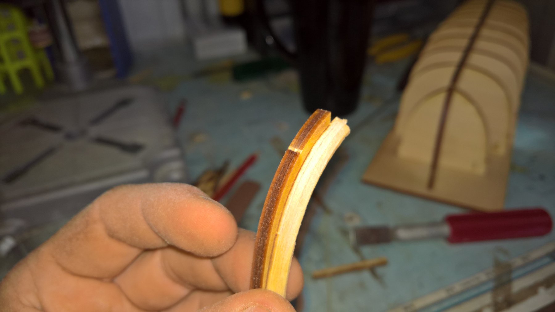
 A litte more than a year ago I started a side-project. I bought the plans for this small boat on a whim, after visiting an excellent exhibition at Rochefort, France (thats where the famous frigate Hermione has its home port). The model is about 22 cm or 8.66142 inches long. Building this little gun-boat gave me great pleasure and quite a few headaches, mostly due to my choice of a small scale of 1:62 (I scaled the plans down to fit the gun barrel from rb-models in Poland). The plans and explanations (ancre.fr) are excellent, available in several languages - even in my native German. Here I will keep my explanations short. I recommend the - as always - very instructive log by Tony with further references. My chaloupe is made from pear, painted in French style of the time (with the exception of the imperial green on the inside, which would made it more historically accurate). So here are the first steps: Keel parts assembled (2 mm pear) The frames (1.2 mm pear) were watered, bent over a soldering iron and pinned on the form (with a shortcut at the stern, where no frames were needed for this model), covered with glossy synthetic-resin varnish. Planking was done with 0.5 mm pear planks To be continued soon...
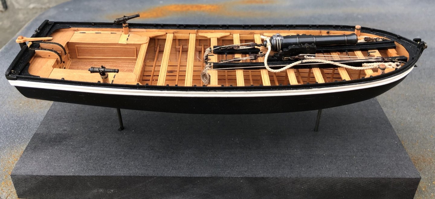


- 14 replies
-
- 8
-
-
- chaloupe armée
- longboat
- (and 1 more)
-
.thumb.jpg.63de63bd9ff3a8188868ac58dfcc309c.jpg) Hello everyone, This will be my first wooden model build - I am super excited and equally nervous. I have chosen the Endeavour's Longboat for two reasons: Artesania Latina kits are more readily available in South Africa I thought it to be a good beginner kit while not being overly simplified in terms of detail, rigging etc. I have gone through the existing build logs here, which will prove to be invaluable. I can only hope that my completed work would look as awesome as other's models, and I may even "borrow" a few of the ideas featured in their posts (with crediting the author of course). I really hope that more experienced modellers my notice my humble post and alert me to potential problems, and also suggest better alternatives as I go along. Last weekend I began the build by pretty much following the instructions and carefully removing the required frames from the plank template. Knowing it was not entirely necessary, I still filed all excess wood from the parts, just because it would bug me if knew it was not 100% flush. After dry fitting, I proceeded to glue down the frames and bow/stern strengtheners. I also placed the main decking and side brackets to help with ensuring the frames are level before grabbing the glue. The following day I proceeded to glue down the decks and the thwart. I specifically did not glue the topgallant bulwark, as I was afraid of nicking it while forming the bow strengtheners, which is what I began doing next using a medium grit file. As mentioned in other build logs, the instructions unfortunately do not clearly show how it should be formed, so I took my time with this step. This was where I had left off for the time being. Once I have completed the filing, I will post more detailed pictures to hopefully help others in the future.
Hello everyone, This will be my first wooden model build - I am super excited and equally nervous. I have chosen the Endeavour's Longboat for two reasons: Artesania Latina kits are more readily available in South Africa I thought it to be a good beginner kit while not being overly simplified in terms of detail, rigging etc. I have gone through the existing build logs here, which will prove to be invaluable. I can only hope that my completed work would look as awesome as other's models, and I may even "borrow" a few of the ideas featured in their posts (with crediting the author of course). I really hope that more experienced modellers my notice my humble post and alert me to potential problems, and also suggest better alternatives as I go along. Last weekend I began the build by pretty much following the instructions and carefully removing the required frames from the plank template. Knowing it was not entirely necessary, I still filed all excess wood from the parts, just because it would bug me if knew it was not 100% flush. After dry fitting, I proceeded to glue down the frames and bow/stern strengtheners. I also placed the main decking and side brackets to help with ensuring the frames are level before grabbing the glue. The following day I proceeded to glue down the decks and the thwart. I specifically did not glue the topgallant bulwark, as I was afraid of nicking it while forming the bow strengtheners, which is what I began doing next using a medium grit file. As mentioned in other build logs, the instructions unfortunately do not clearly show how it should be formed, so I took my time with this step. This was where I had left off for the time being. Once I have completed the filing, I will post more detailed pictures to hopefully help others in the future.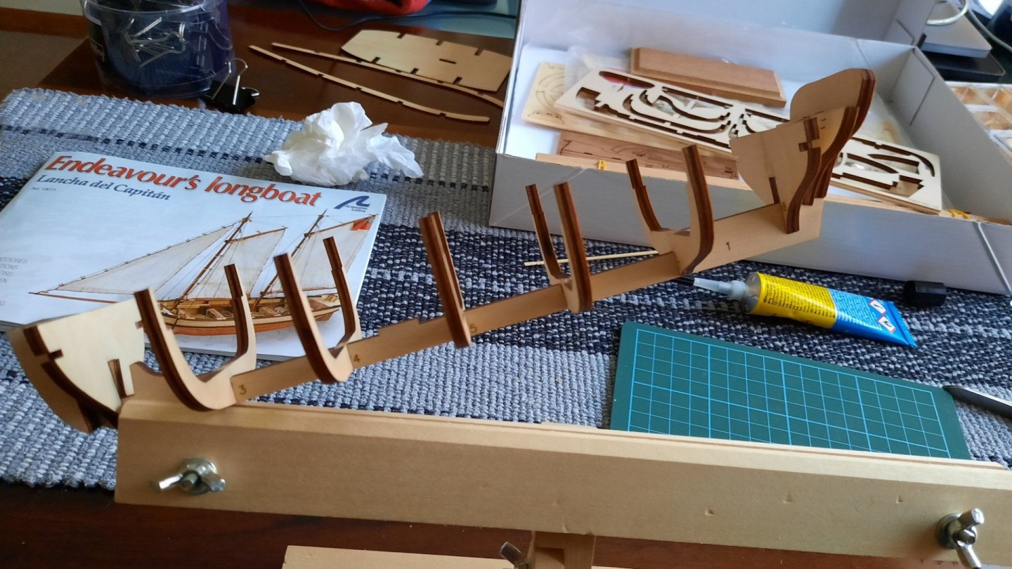
- 2 replies
-
- 4
-
-
- artesania latina
- Endeavour
- (and 2 more)
-
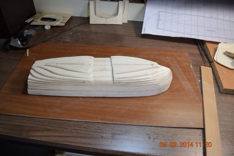
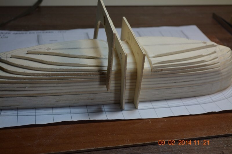
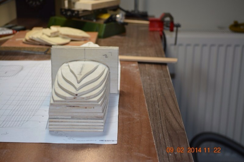
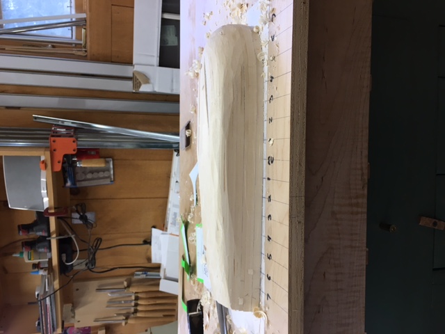
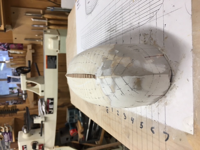
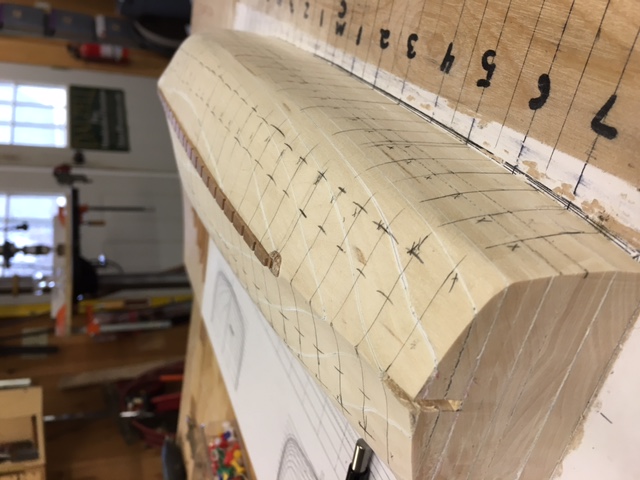
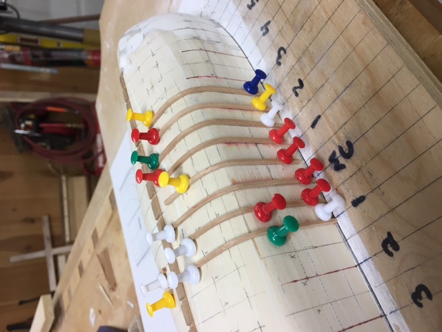
 It has long baffled me How many of the great modelers make such superb work boats That service the sailing ships of old. I had made many attempts but always felt that the finial product fell short of the Main ship model. One day i came across A post that suggested that these magnificent miniature boats were made using a mold. I looked everywhere to find a paper or video to help me try but never found a complete process. So i decided to try to develop the process and recorded my work on video. The first one did not pop out of the mold but the second one did. The finial product was great if i may say so myself. Attached are the tree videos on the project. Part 1 Part 2 Part 3
 -
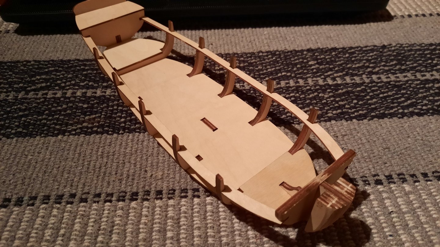
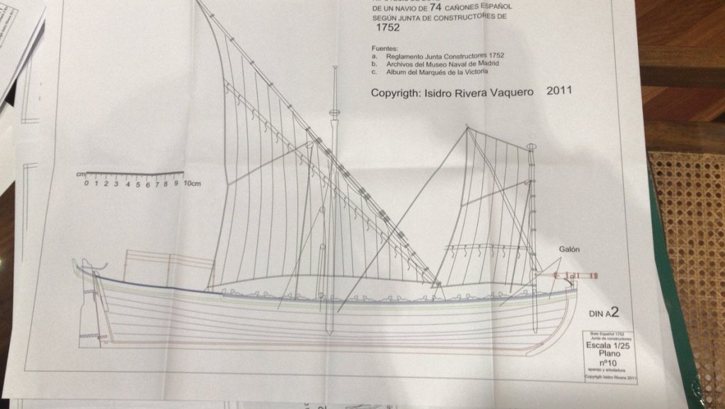
 Hello all I want to share this construction log, about the Spanish Longboat, that could be converted to Falúa (Luxury Longboat for Officers). The plans have been developed by Isidro Rivera, well known spanish naval researcher, who has many papers, books and plans already published. I have the fortune to be in contact permanently with him, Jose Collado who is his partner in construction, and a bunch of really good guys, who are always, willing to help when I need it. I started the 17th of February and.......
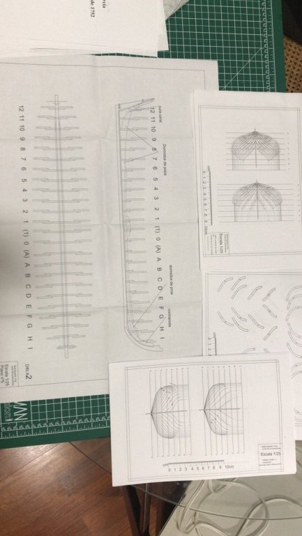
-
 Hi all I am looking for info on how the cutters were secured or lashed to the skid beams. Right now they are sitting in small cradles. I was going to put some eye hooks on the beams on both sides of each boat and just run a rope from the eye, over the boat and then down to the eye on the other side. I would do this both fore and aft for each boat. Any possible solutions would be appreciated. thanks Tom
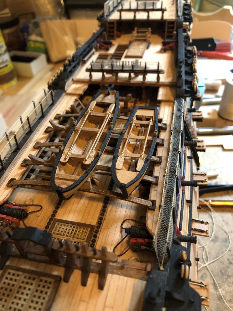
-
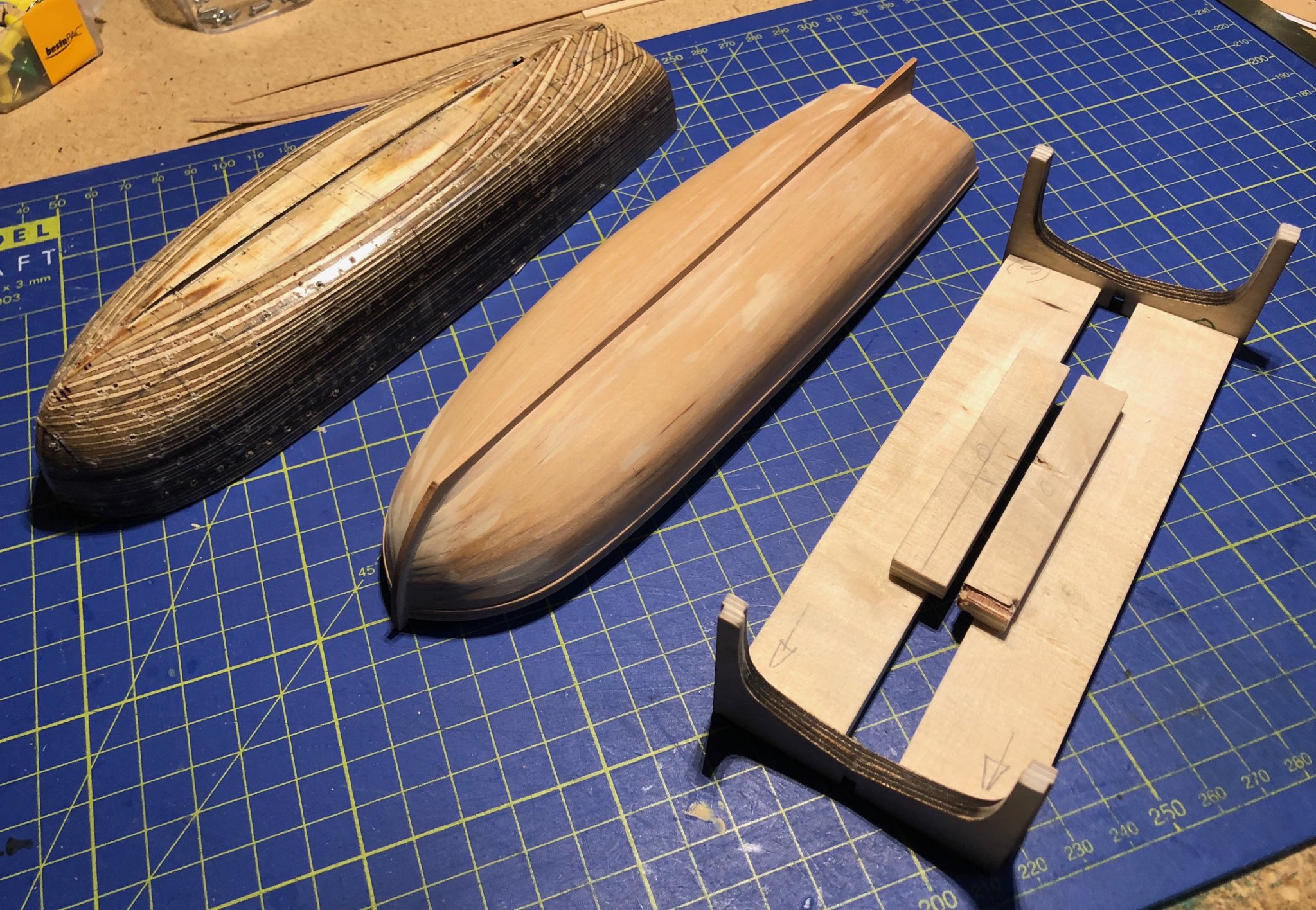
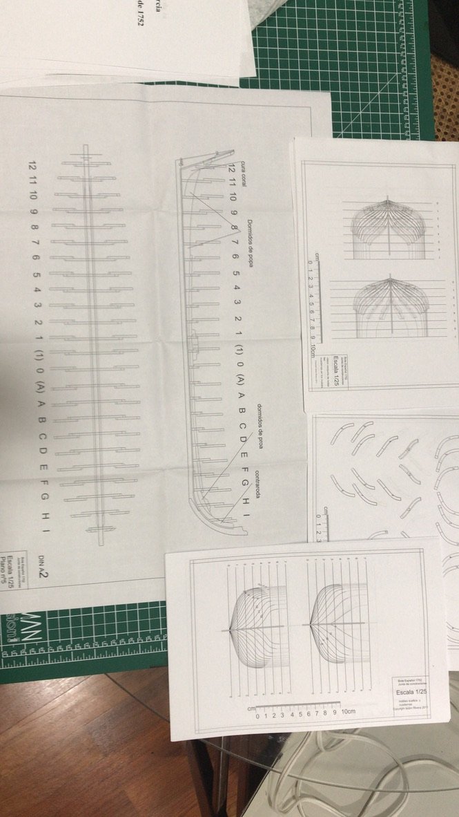
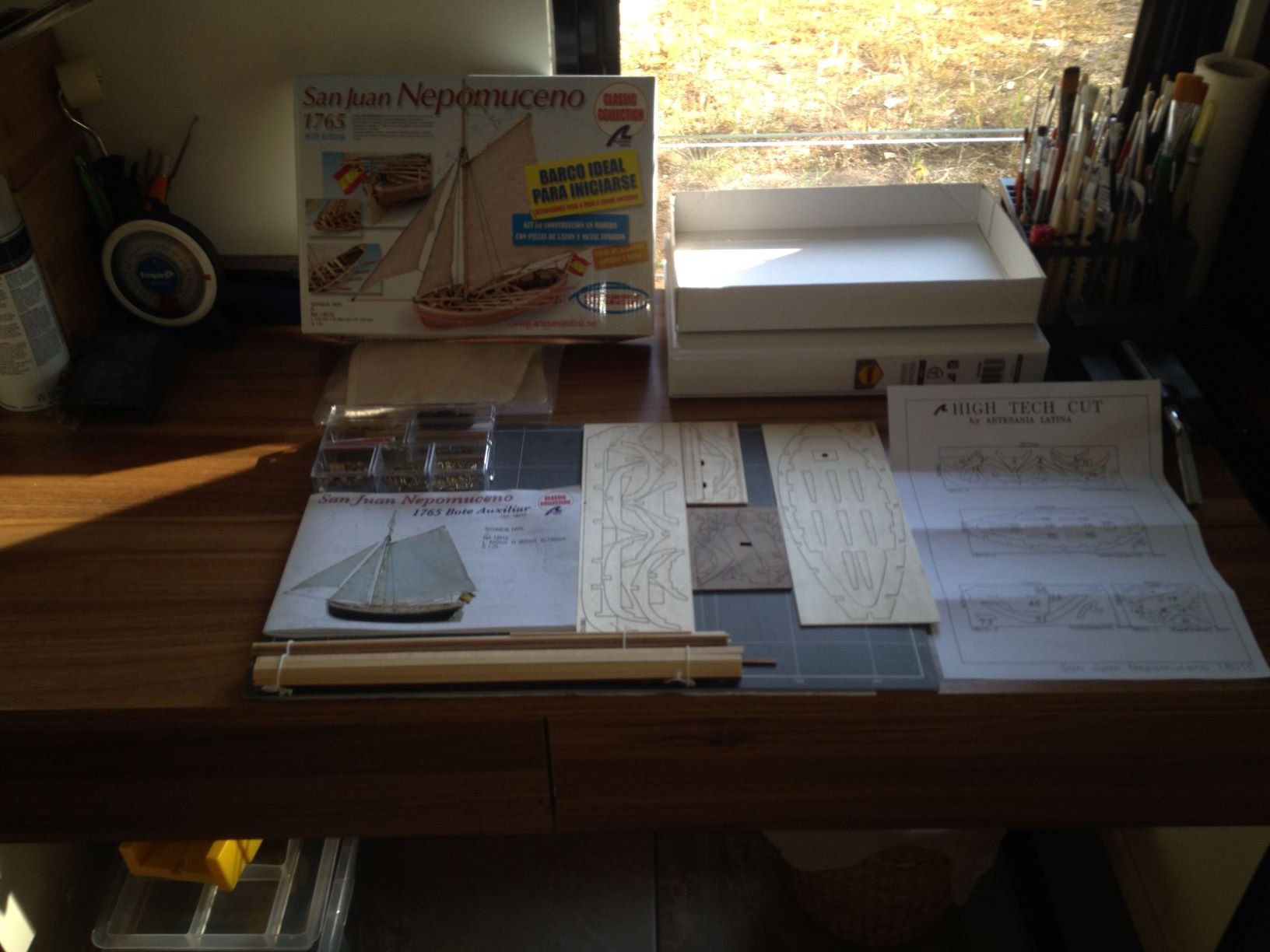
 Well my first ever wooden ship build will be the San Juan Nepomuceno - Boat Auxiliar a cheapish model I picked up from an online retailer (BNA) here in Australia. Without much further ado here is a photograph of the kit unboxed. I had to scale this down as I believe there my be a limit to image size on the forum.
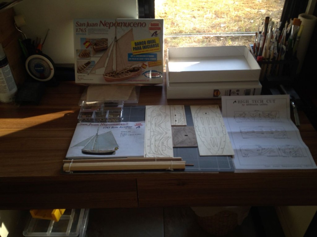
- 5 replies
-
- 5
-
-
- san juan nepomuceno
- artesania latina
- (and 1 more)
-
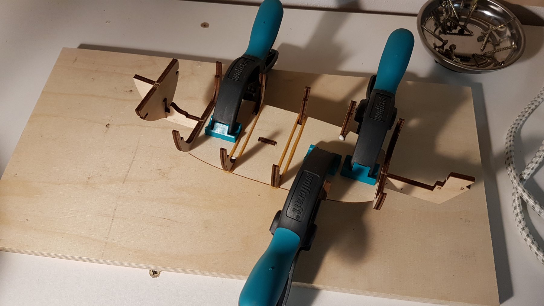
 Well, as threatened in my introduction i will post my first building log. First picture is taken several hours past the beginning. I removed the bulkheads from the frame with a scalpel nr.3. This was easy and only a little filing was needed at the connecting points, because the thin scalpel cut very accurate. One little error in the provided laminated wood was that it was delaminated at one point of the frame. Two parts were affected. The deck in the aft and one base of the thwarts were affected. The deck could be repaired by putting some white glue on a toothpick and distribute it inside. As that base of the thwarts is only 7 mm wide it cracked even more in the process. I repaired it with a splint about half as wide as the base so it should not be visible. The fit of the bulkheads was pretty good out of the box. After dry-fitting, I saw that deck was slightly too long at the aft, but it took only a little sanding. The first frame and the last frame needed a little adjustment to be in one plane with the rest. I discovered this only after fitting the base of the thwarts in addition to frames and deck. After everything seemed to fit squarely, I glued it together.
- 5 replies
-
- 1
-
-
- longboat
- artesania latina
- (and 1 more)
-
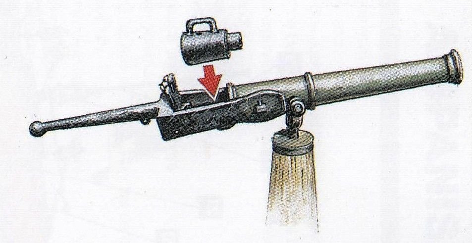
I am considering whether to arm my 'armed' longboat of 1834, and while doing so I'm looking at the type of swivel guns used. In all the models of this I've seen a standard muzzle-loading swivel gun is depicted, as it is in the plans of M.Delacroix from which I am working. However, I was wondering whether this type of longboat might have used breech-loading swivel guns as these were popular at the time and provided more rapid fire than could the muzzle-loaders although they were less reliable. So if there's anyone who's knowledgeable about this please do chip in with your opinions. It may be that I don't end up putting any armament on the longboat, but I'm still interested in the question as may others be when considering the type of swivel gun to use on their models. The following is an illustration of a breech-loader that was put up on Pinterest by Brian Walters Thanks Tony
- 9 replies
-
- 1
-
-
- swivel guns
- cannon
- (and 1 more)
-
 By now, I can't return to my Le François model. A member of my family likes a lot models from scratch, so I thought on a small one, a longboat. So, it will be a present for her. Based on Jean Claude Lemineur's monograph: The Ship's longboat, I will make it at 1/36 scale using just pearwood. Of course, I don't forget my previous project: Le François.
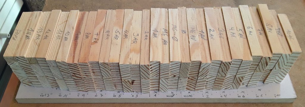


-
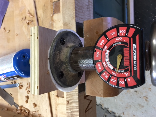
 Initially, my "go big or go home" way of thinking was pushing me towards a big beautiful 3 decker with an extensive built log to go with it. Fortunately, while living in this dream world I realized I didn't want to be one of those guys that starts a build and never finishes it. So instead of cutting teeth on a ship, I decide that building a boat was a more appropriate place to start. With that said, I decided on Chaloupe Armee En Guerre 1834 otherwise known as a Longboat Built For War. I purchased the plans from Ancre. They are well done and are accompanied by a 40 page method of construction booklet. Here I am, many months in to the build and I have decided it's time to create the build log. I Initially decided to wait on the build log until I was sure I was capable of finishing. Over the next few days I will post pictures etc..until I am caught up. Thanks to all for creating a great site to hangout in. Shaping the mold was my first challenge. Getting it right proved to be a daunting task. The picture below shows where I got a little carried away and had to add some filler to bring it back to where it needed to be. At this point I should say that I'm using Cherry to build this boat. I was able to bend the frame members by soaking them in alcohol (Gin) for a couple of minutes. For the most part, it was a pretty straight forward process. Attention to grain direction was important to getting a splinter free bend. For bends that needed a little extra help, I made this make shift bending iron. FYI, these photos seem to be a little compressed, I will try to work on that.
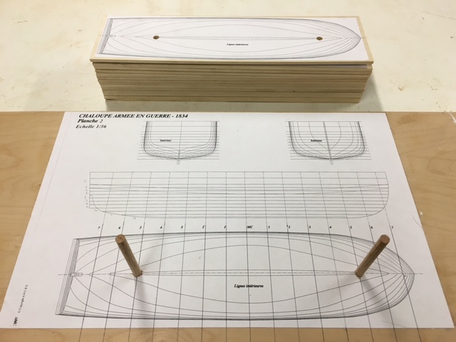
-
 Hey howya goin all, this will be my third build log of a ship and will be my first scratch build of a boat. I will be starting this build when I get my scroll saw which will be nere the end of june and the timber not to long after that if I stop been lazy and finish the list of timber I need, I was thinking of using Walnut , I plan on making two of these one with the cannon on it and one with sails on it. Longboats are designed to be carried by warships; they are stowed on the upper deck between the gangways, resting on chocks fastened to the deck. With the longboat aboard, the barge is placed inside it, while inside the bargeis the cutter. The longboat's thwarts are removable, allowing the barge to be stowed more snugly. Longboats are the ship's boats most commonly used in the Navy for transport of the heavier loads so frequently required by the warships. Their broad, generous lines are suitable for the diverse tasks which they are called upon to perform: carrying the anchors, a common task when mooring, shore duties, watering parties, carrying stores when the ship is in service. From time to time however they may participate in more warlike activities: harbour defense or the protection of landing troops and raiding parties. Under these circumstances, they are sometimes armed with a single gun, an 18-pdr, 24-pdr or even a 36-pdr. It is then that they are described as "armed boats", and it is this arrangement which is to be seen in this model. It should be noted that there is a distinction to be drawn between armed boats and gunboats: despite the large gun carried by the former on the thwarts, it remains a classic ship's boat, whereas gunboats are larger in size, are frequently decked, and may carry several guns. So heres what I got so far. The one with the sails I'm making I had to order the plans for the sails separately as they don't come in English like the other plans I will be scanning the French language manual into my computer mybe a PDF file and copy and paste it to Google translate to translate them to English.


-
 This is my first attempt at a wooden ship build. I come from a background of plastic model aircraft, radio control aircraft (fabric over balsa) and recently a foray into plastic model ships (CVN-65). I got the bug for model wooden ships after discovering the work a mate of mine did while helping his father clean out his possessions after his untimely passing. I inherited a box of spare parts, cannons etc and could feel them calling to me. To be honest the thing that intrigued me most about wooden ship building was the rigging. I am a perfectionist. Just ask my wife. So I purchased a kit that would allow me to practice plank on frame hull building as well as rigging. I wanted a kit that wasn't too expensive in case I stuffed it up. I picked the Endeavour longboat because of 1. The ties to the history of the discovery and settlement of my country 2. It looks pretty 3. It has three masts so I figured more rigging to play with, even though I know there are lots of comments on other logs that the longboat would almost certainly not have had 3 sails! I should have started this build log a long time ago, and for that I apologise. I also should have taken more photos, but I will attach the ones I have. I have learnt a lot of things doing this build. I have made quite a few mistakes, although I believe I've recovered from most of them fairly well. I have an ulterior motive for posting this build log, I have a serious issue with the rigging which will be detailed in a future post, and I am hoping for some advice. Cheers, Andrew.
 -
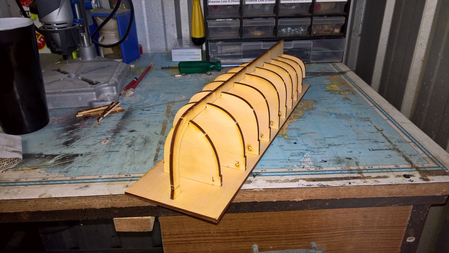
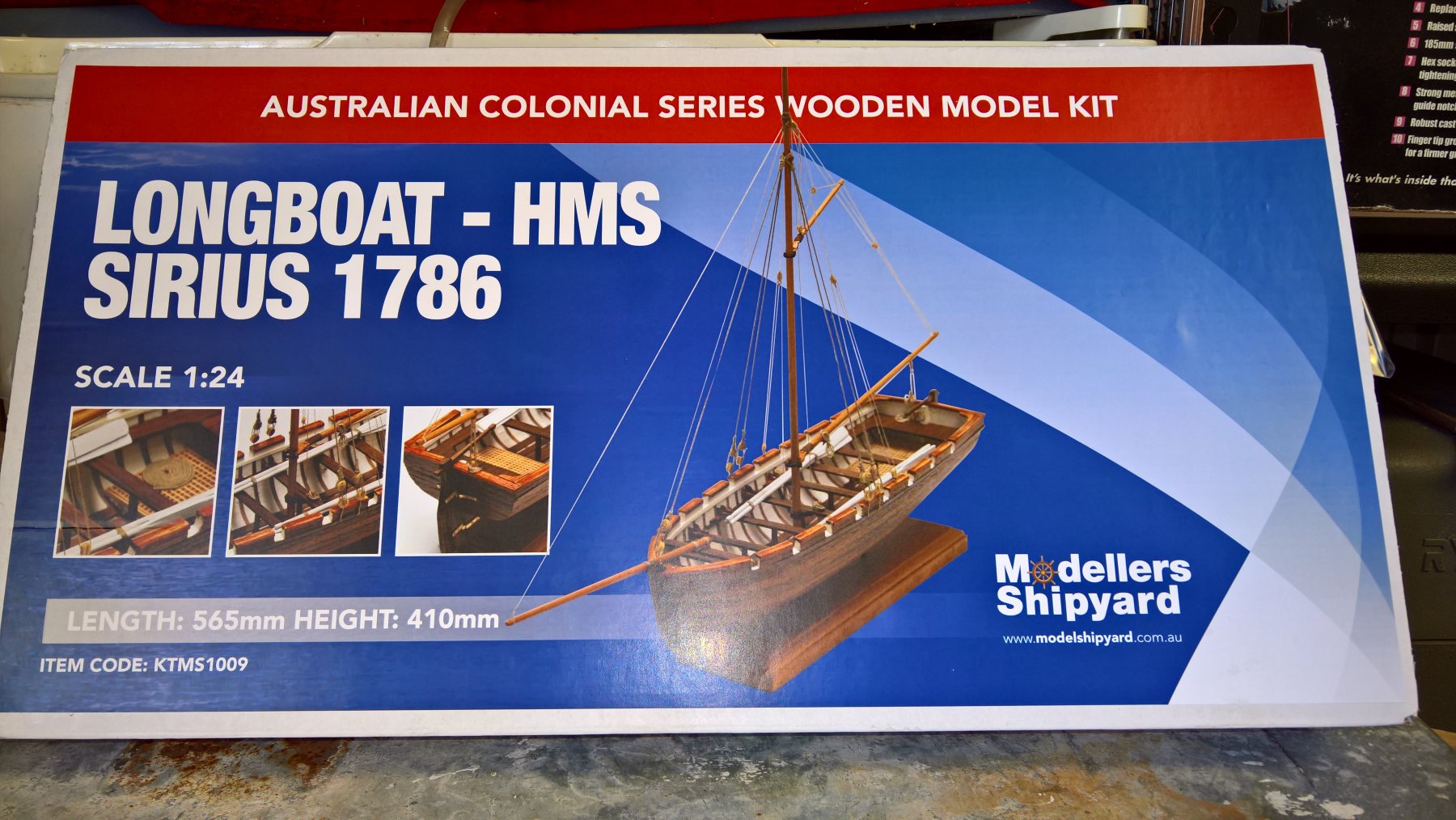
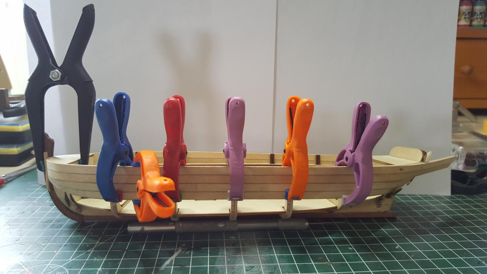
 Good day all! After an extended hiatus I'm back in the shipyard! Today I received my next project, the longboat from HMS Sirius, one of the first fleet ships. The box in which she came! Next is the contents of the kit spread out. First step was to lay out the frames and put the keel in place. The frames aren't glued to the baseboard so once planked it can be removed from the internals of the longboat, it is there to provide the framework to build on to. The transom is glued on to the keel however. Next was to shape the bow blocks with a 45 degree bevel. To do this I used my rotary tool in the Dremel drill press with a sanding disc on it. It made the job faster, easier and did a great job!
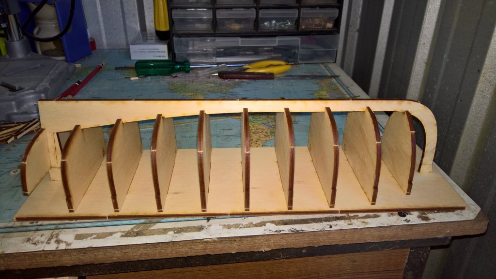

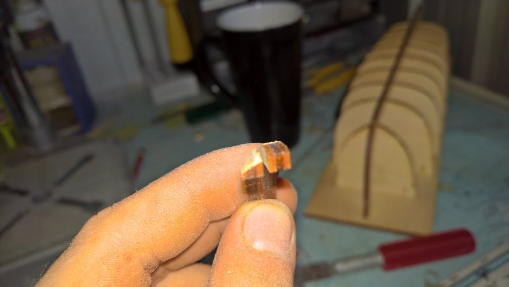


-
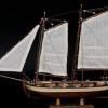 Hello guys, As a newbie I started my first project in wooden model ship building with a starters model from Artesania Latina. It comes with a handy step by step instructions manual and because of this I can learn how to build the basics. I always wanted to be able to do this because I love wooden boats/ships and thanks to this starters model kit I can get an idea of how to build one and loving it all the way!
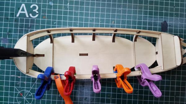
- 32 replies
-
- 10
-
-
- longboat
- artesania latina
- (and 1 more)
-
 G'day everyone, I have started my first wooden boat build, and I am absolutely loving it. But... I am lost on a lot of the directions supplied in the manual. So if I could ask the more experienced model builders for help , that would be great. I think I have glued the stern bulkhead incorrectly? Also, when first planking should, the plank sit flush with the keel? And also is this alignment correct on the first plank? I have a million questions but, I will leave it for now
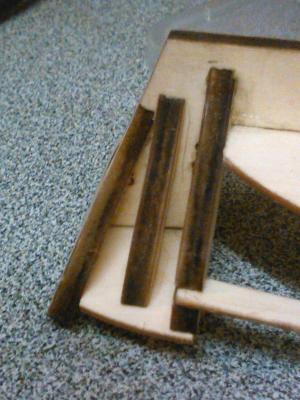
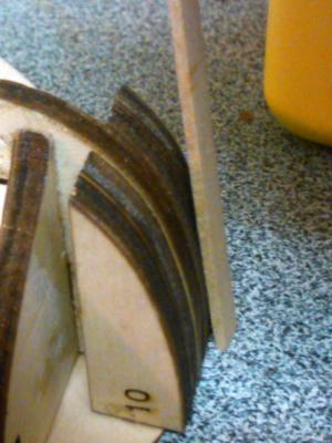


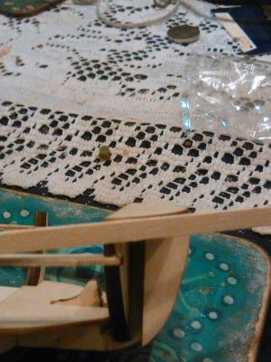
- 7 replies
-
- 3
-
-
- longboat
- artesania latina
- (and 1 more)
-
 Hi all I am new to the site and hopefully as soon as I get some pictures up I can show where I have got to with this my first build. I have now reached the rigging stage and like many a newbie I am daunted to say the least. I have already sited the main mast and the bow mast before I read that it is best not to do so prior to doing some work on them. I am now in the throws of putting together tackle blocks however my issue now is that from what I can see I need to put the sails on the masts which then makes it very difficult to site the blocks. My question is as such, can I just rig the boat first and then try and put the sails in place or is there a trick or two I can learn? I am doing loads of reading as I want to prepare a lot of the items as close to how they should be made as possible, I am taking things pretty slow and will attempt a few newbie builds which will give me the principles to try something bigger in the future. If anyone has built this model I would be grateful for any decent pictures as the rigging instructions with this kit are near on hopeless to someone who has no real idea. Thank for any help and I will get some pics up tomorrow hopefully before I go and see the Who live in London on Saturday.
- 6 replies
-
- 3
-
-
- artesania latina
- longboat
- (and 2 more)
-
 Hi, This is my first post on my small boat build. I am a total novice - having inspired by great builds in MSW, I tried this Long Boat. I did not had any plans, followed some photos. No kits or to any scale. Totally scratch built. During the last eight months, this has given me a lot of satisfaction and learning. I have followed some wonderful builds in MSW. Though this (my first boat) may not pass for any standard model with experts around in MSW, being a novice, this is my crude attempt to learn ship modelling There are many mistakes. I expect you to point out each and correct me so that I can learn and plan for another model. If I am allowed I will post some more pics. The model is almost complete. Regards, Rao A.L.G.
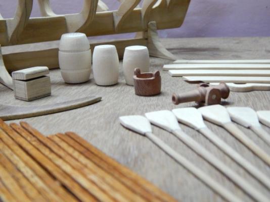

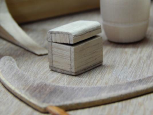
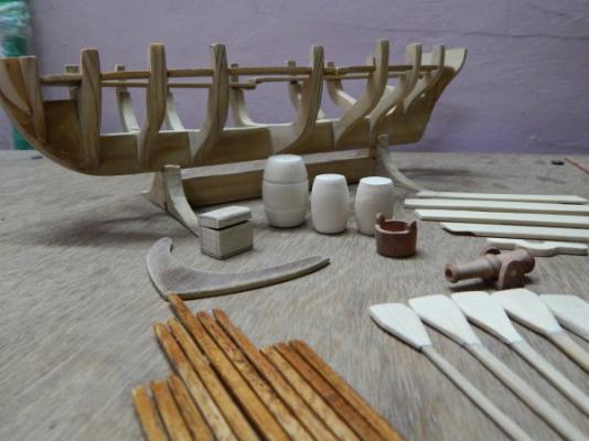

-
 Hi everbody, i will share photos of my new model , chaloupe armee. I m waiting your comments.
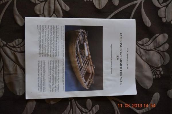
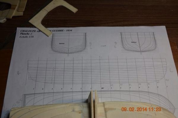
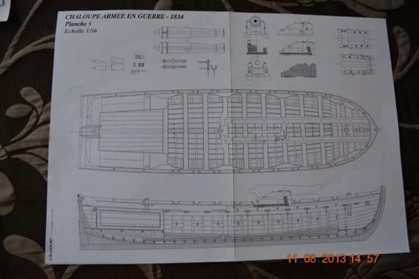
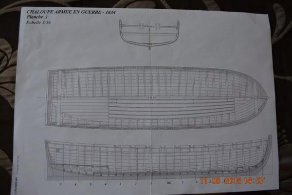

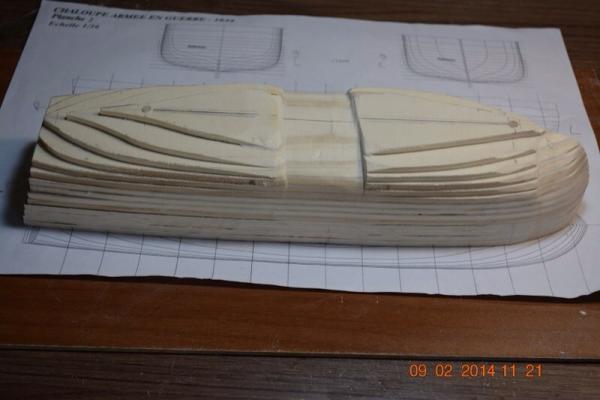
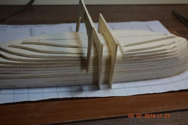


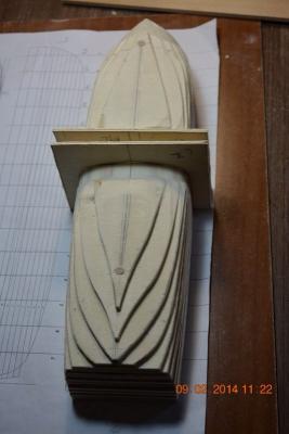
cropped.png.c8c93436d7610c3581cdbc09ea2ce9a1.png)
cropped.png.286b2028d1ca0338407d4c72ed498302.png)
cropped.png.29efca76a26ca49cda3081d3913546ce.png)
cropped.png.9d03b140631b911b5592c085f23d0882.png)
cropped.png.2429495eb2041286ca7e3ec7b3d6ff54.png)
cropped.png.de239418595fea8a7b28e0ca036b8a70.png)
.png.22678a93620cdcd26f6295ff1df95f2b.png)
.png.66c47f3989a8c254bdb704f74bdd5e86.png)
.png.7f90347b3e8d8303c19635dd79cbb817.png)
.png.2c9727e8d613bb213ccd41a6f383fb90.png)
.png.003075eee1a91a420c6bed53b164b5e6.png)
.png.04d0f8455b35481cc3a4140bec2ff510.png)
.png.f4d7e016567ae28d9336b7ccf6a7b8af.png)
.png.a82fcfa105398891a7592ea240684306.png)
.png.1ae74c7abf234c937b2fa115309d4ccf.png)
.png.5a1bf2b8a15d6caaaf5aefd8d64d5cc6.png)
_RMG_J0267.png.fe2e020cad34eb04db9f0d0b737ec922.png)
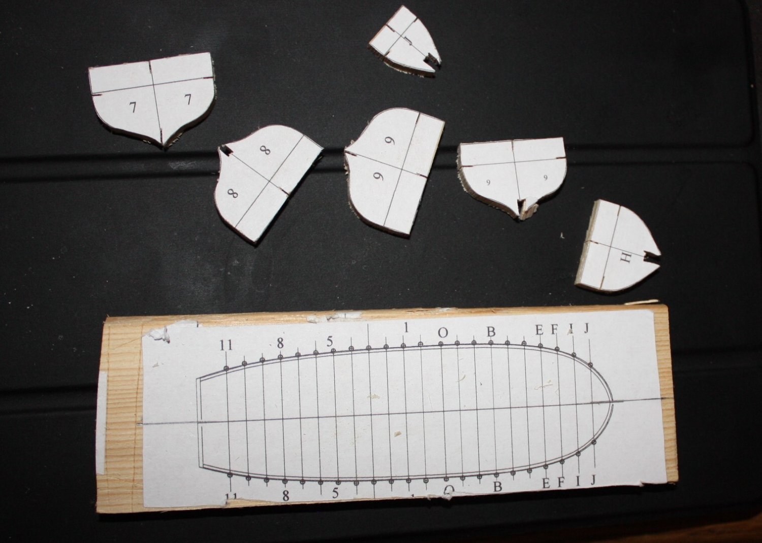

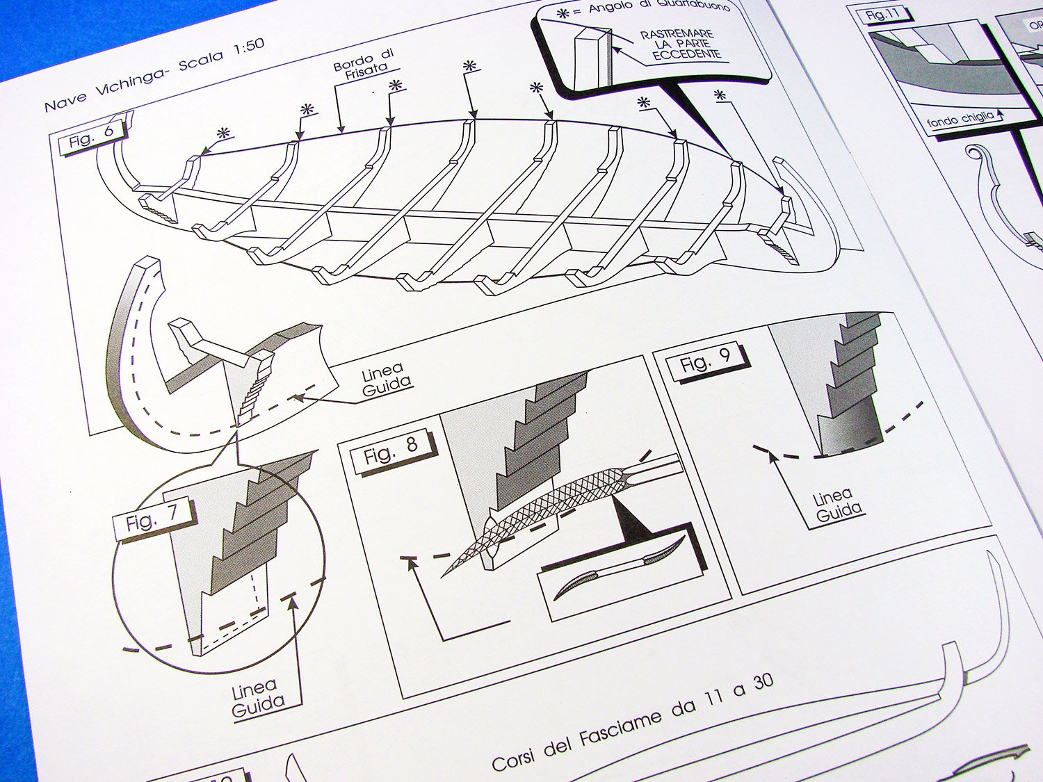
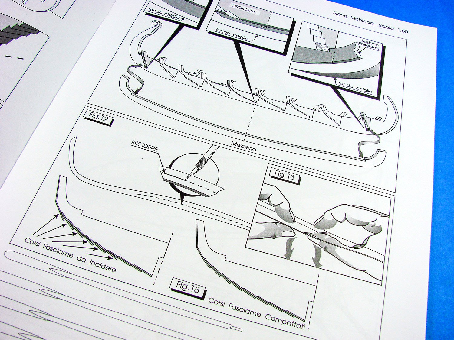


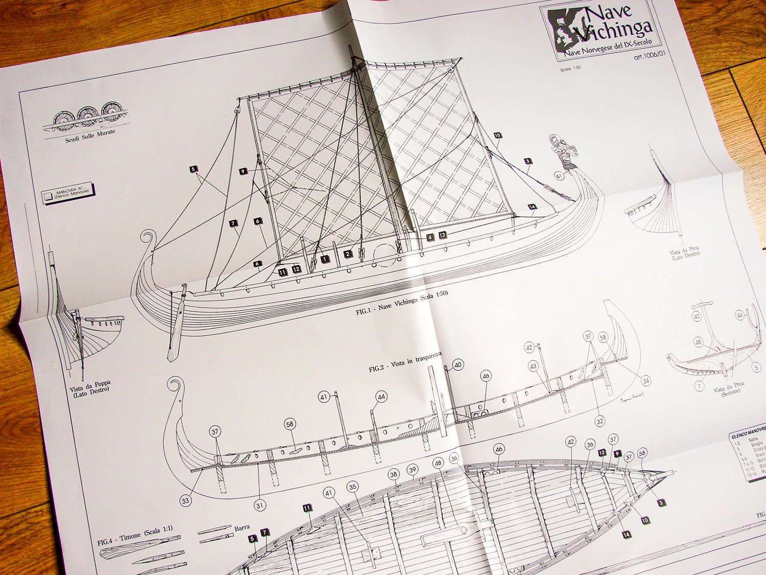
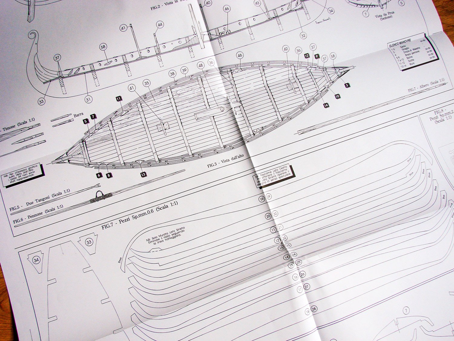
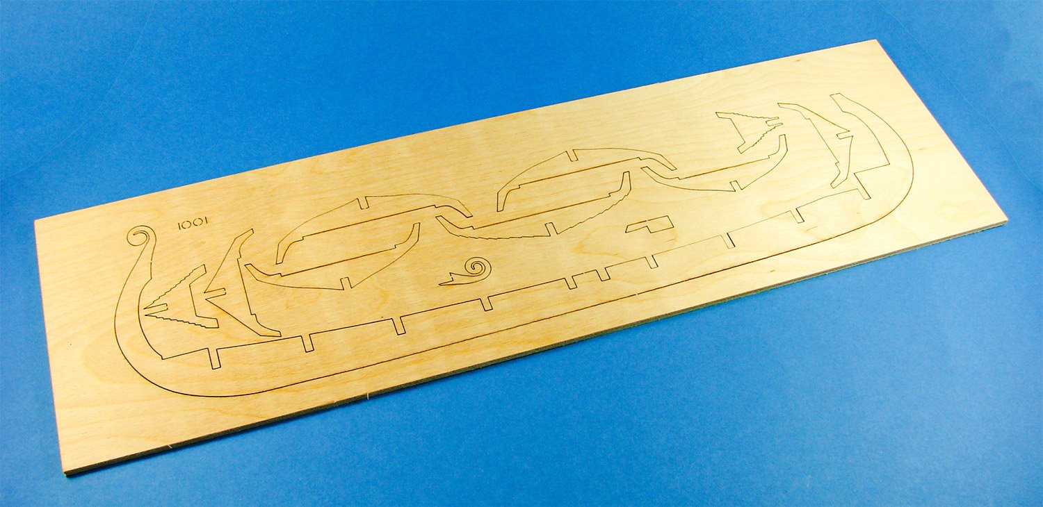
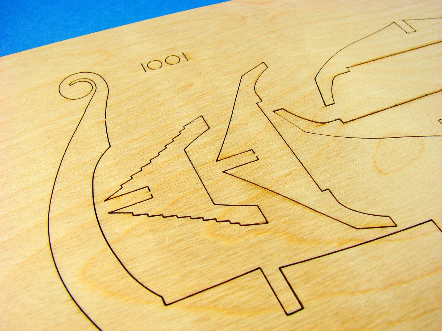
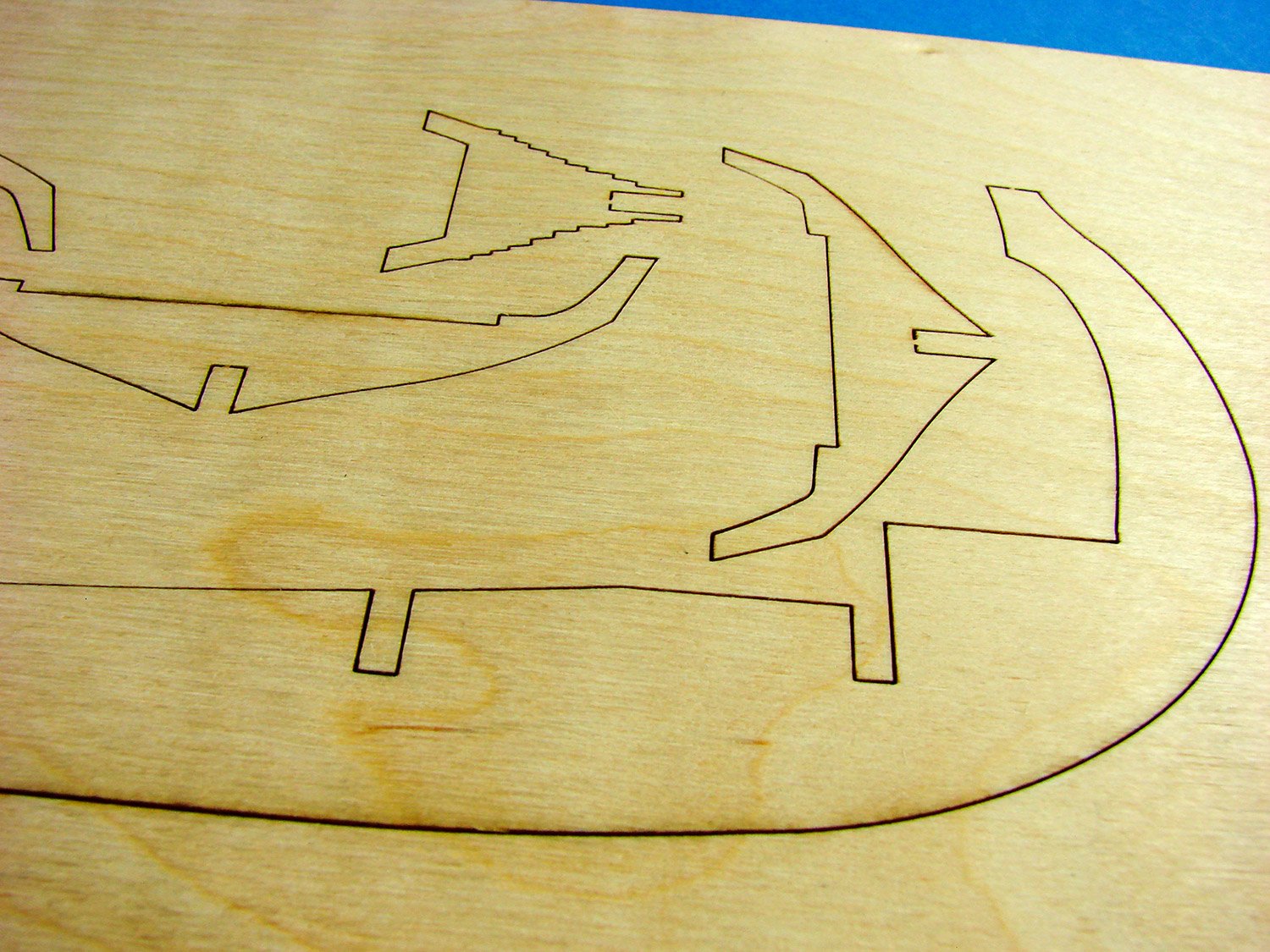
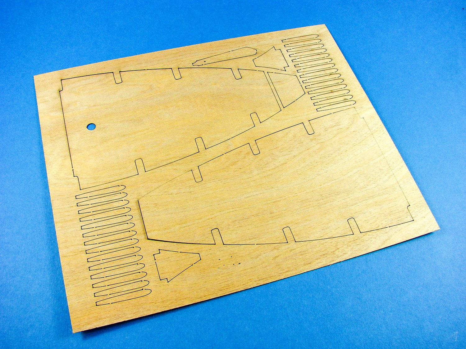
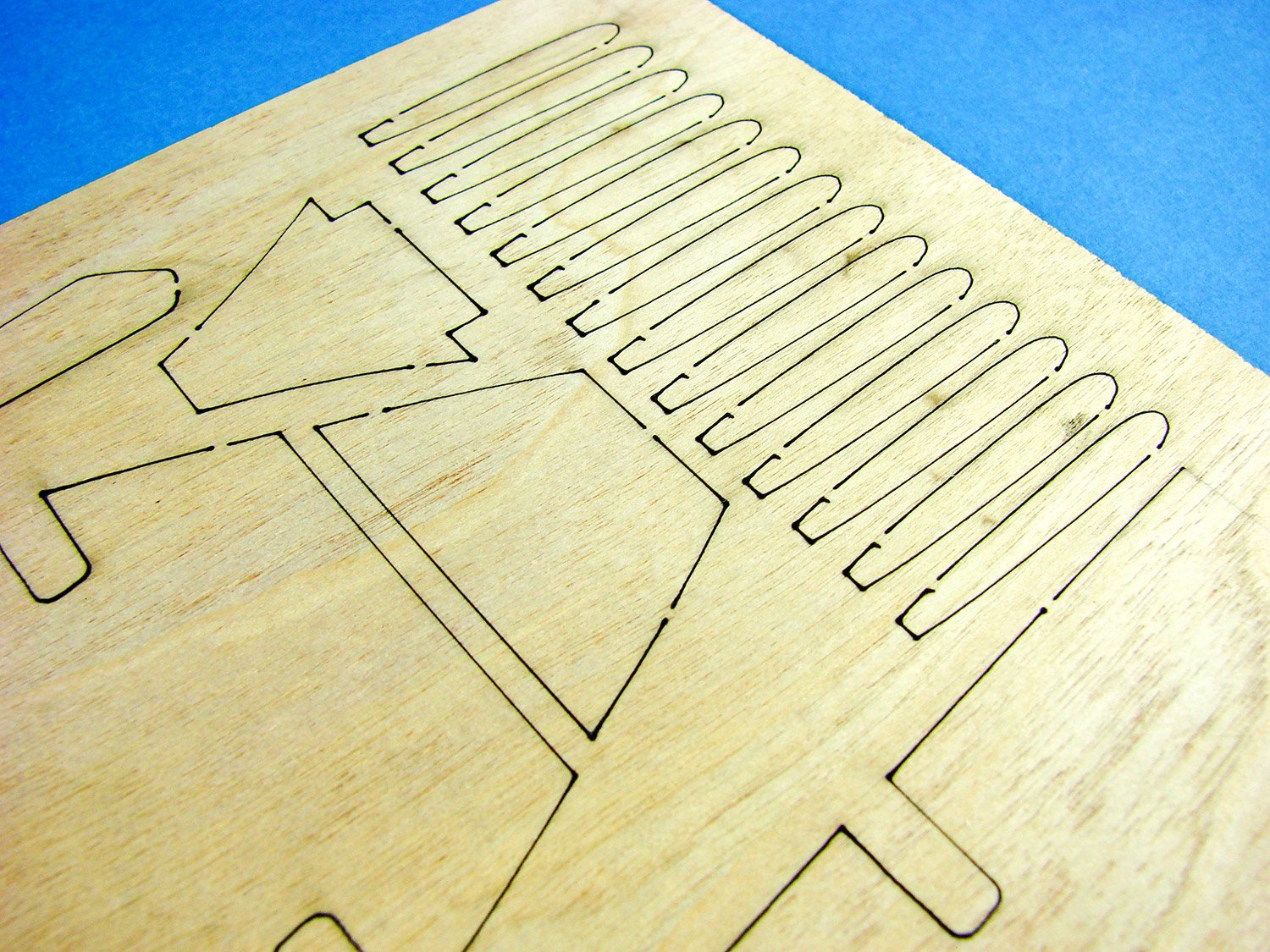
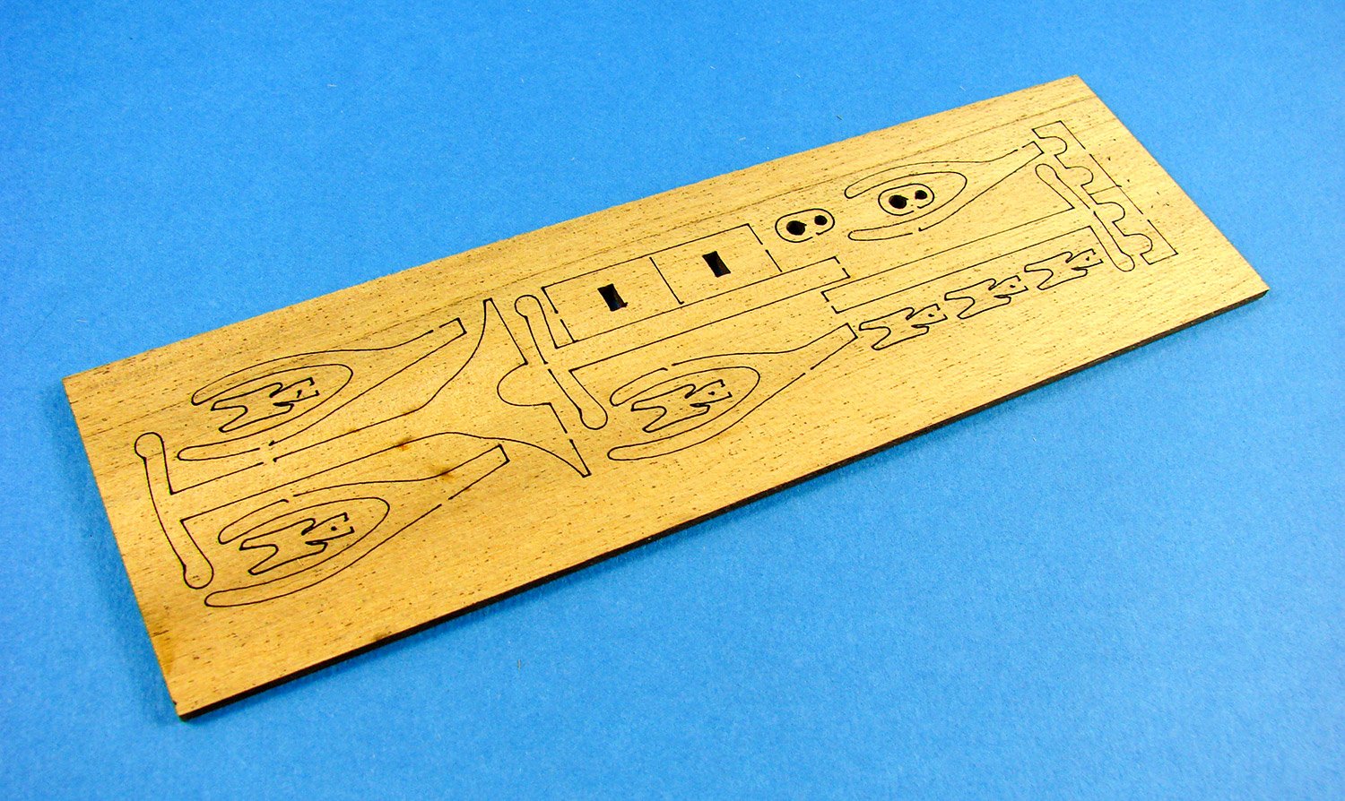
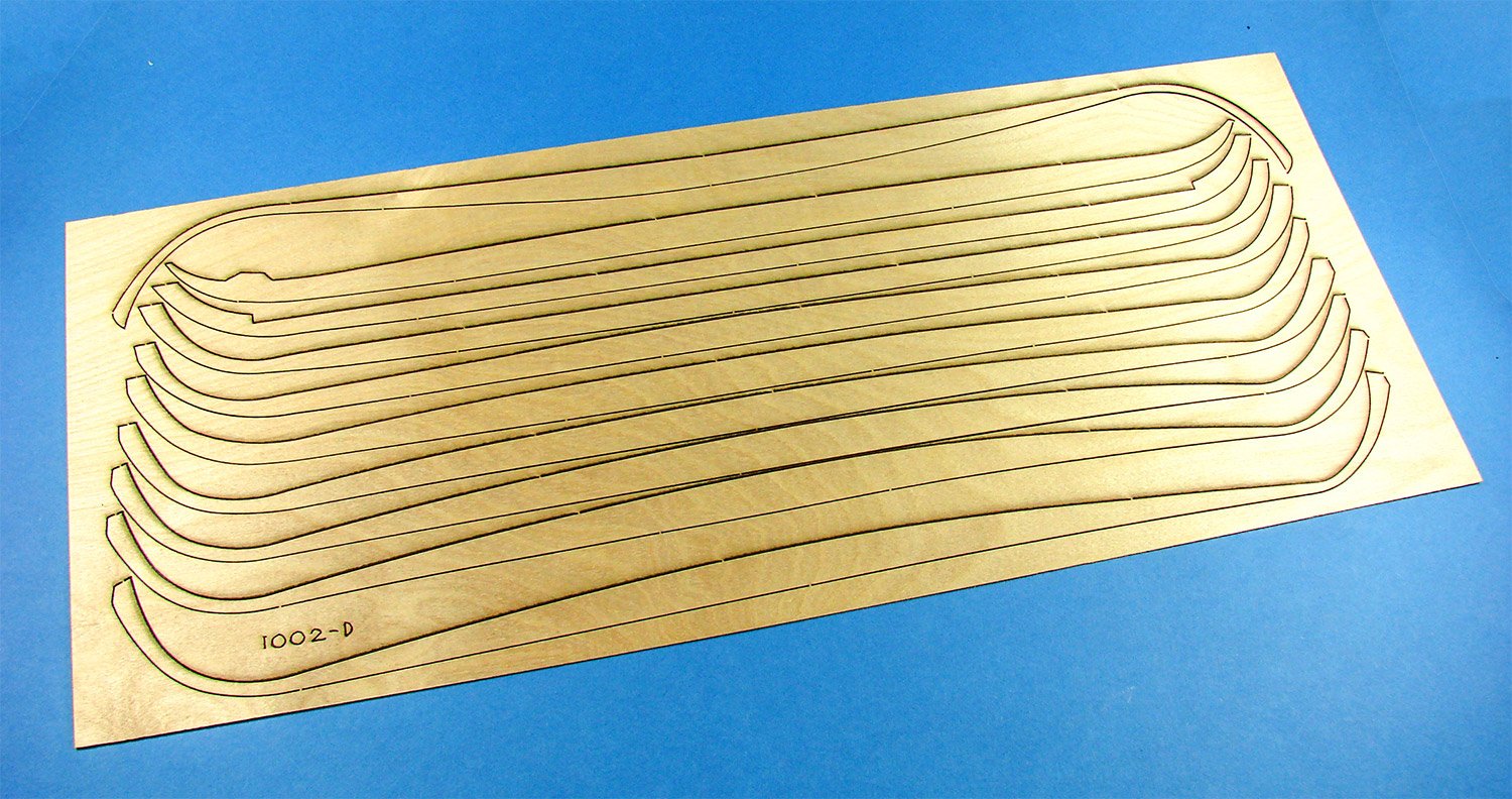

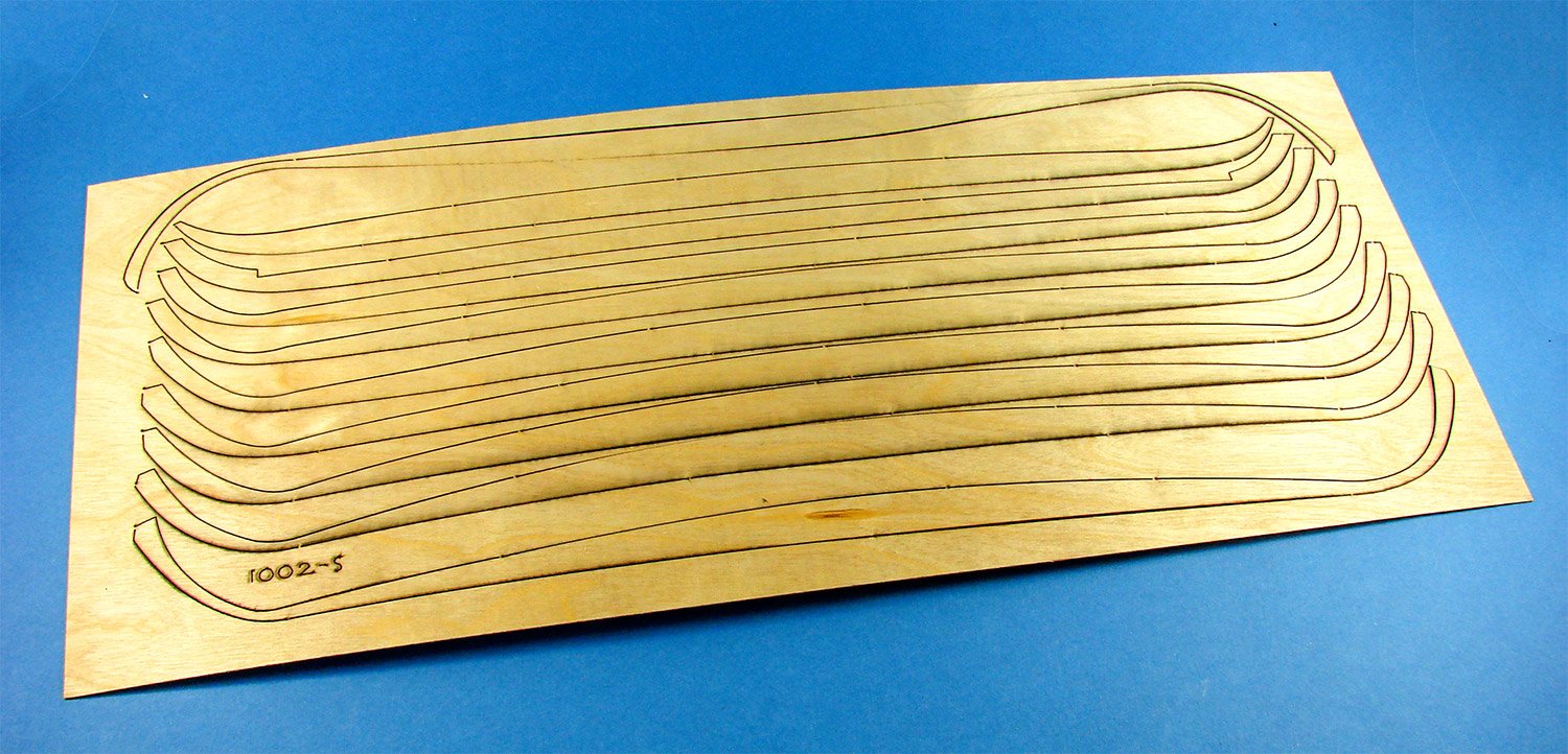
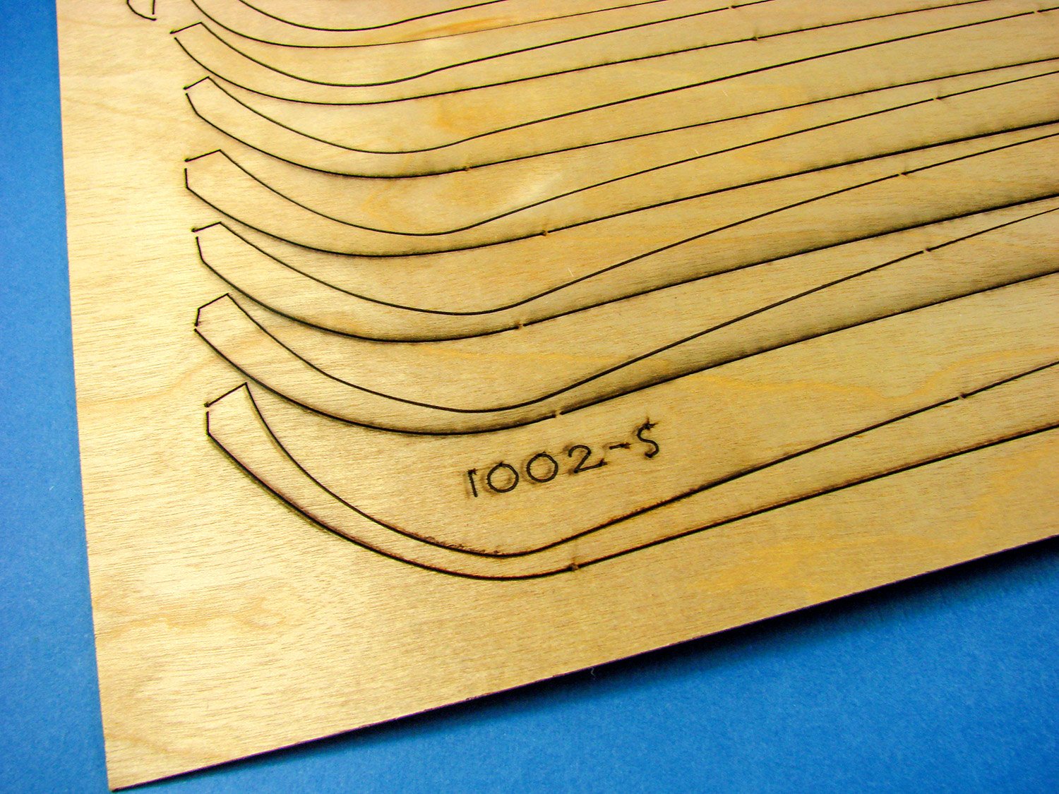


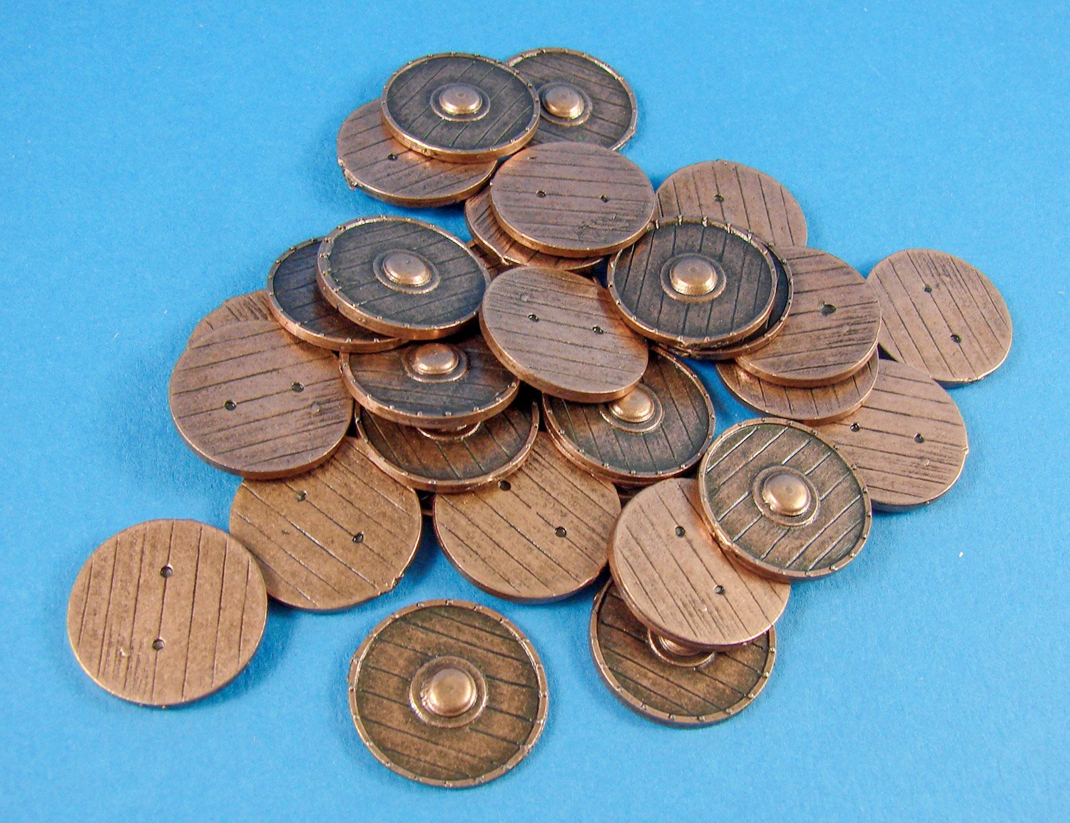
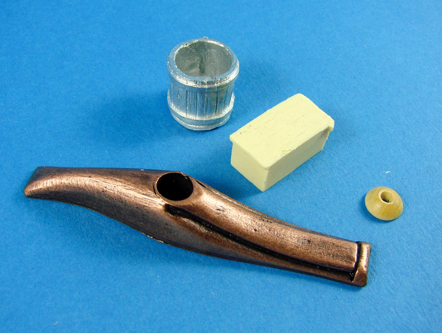
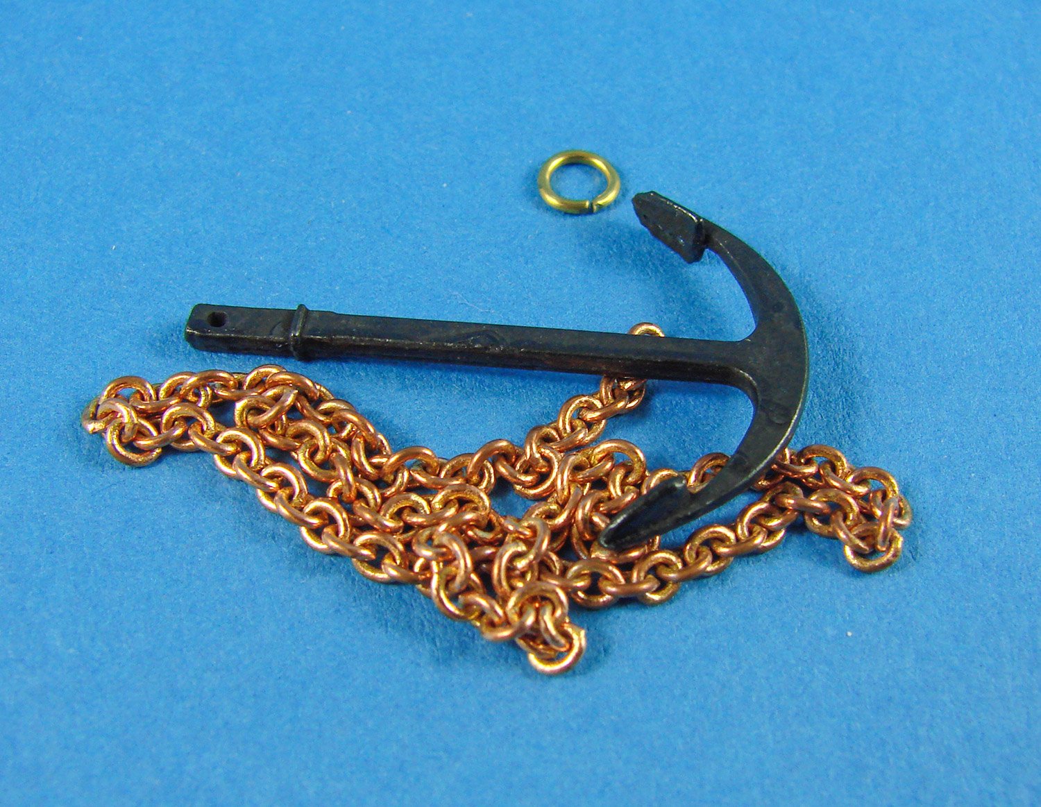
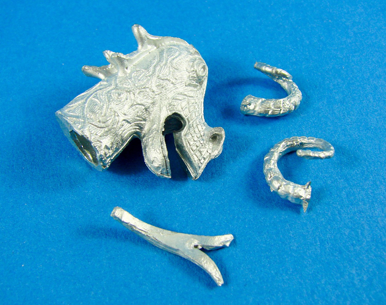
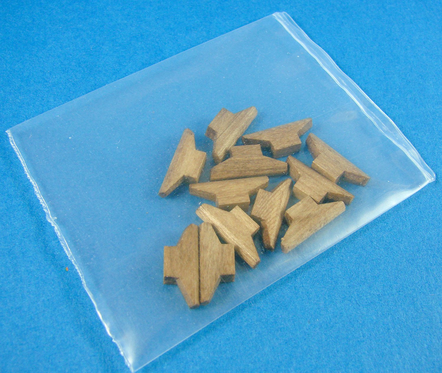
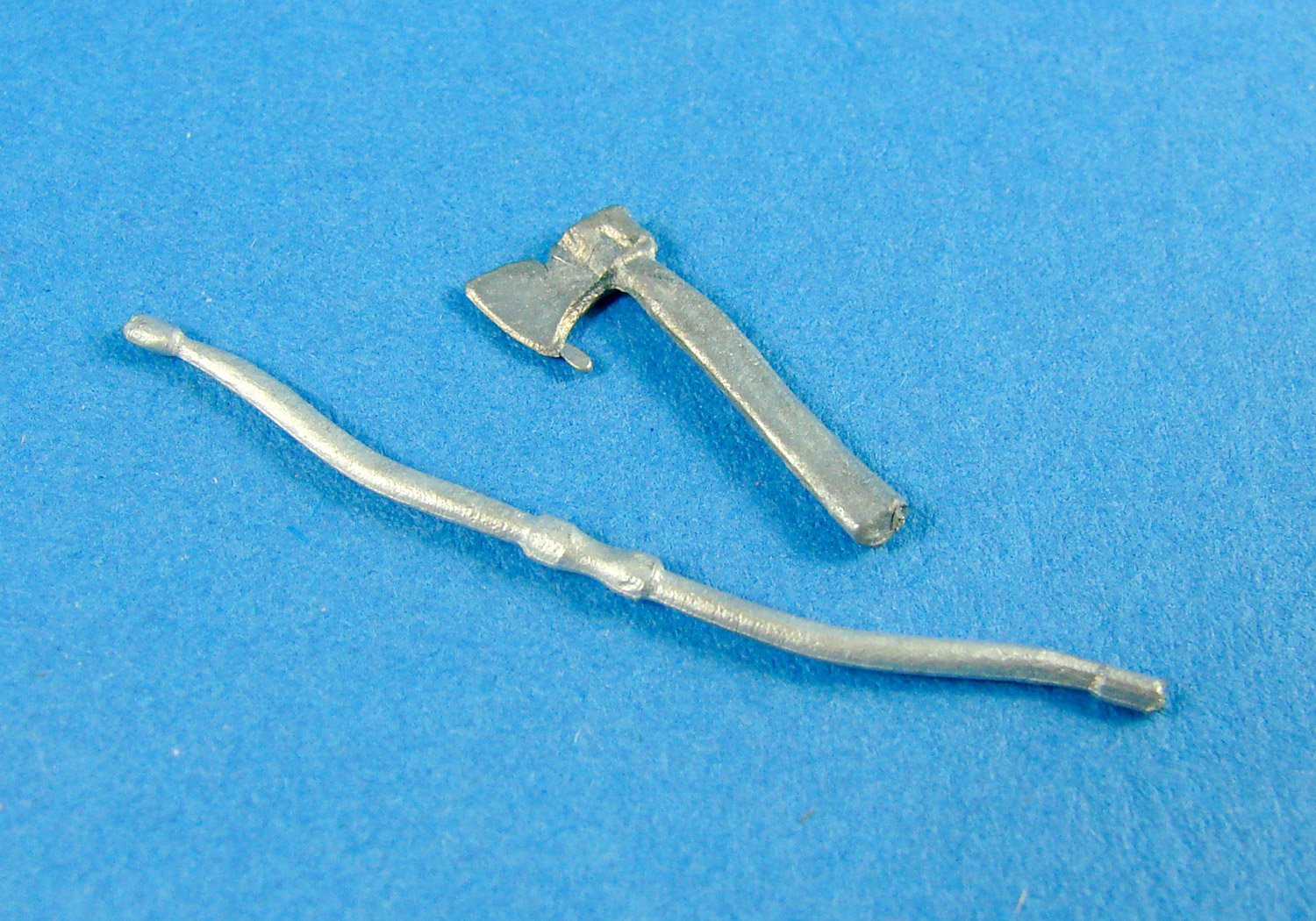


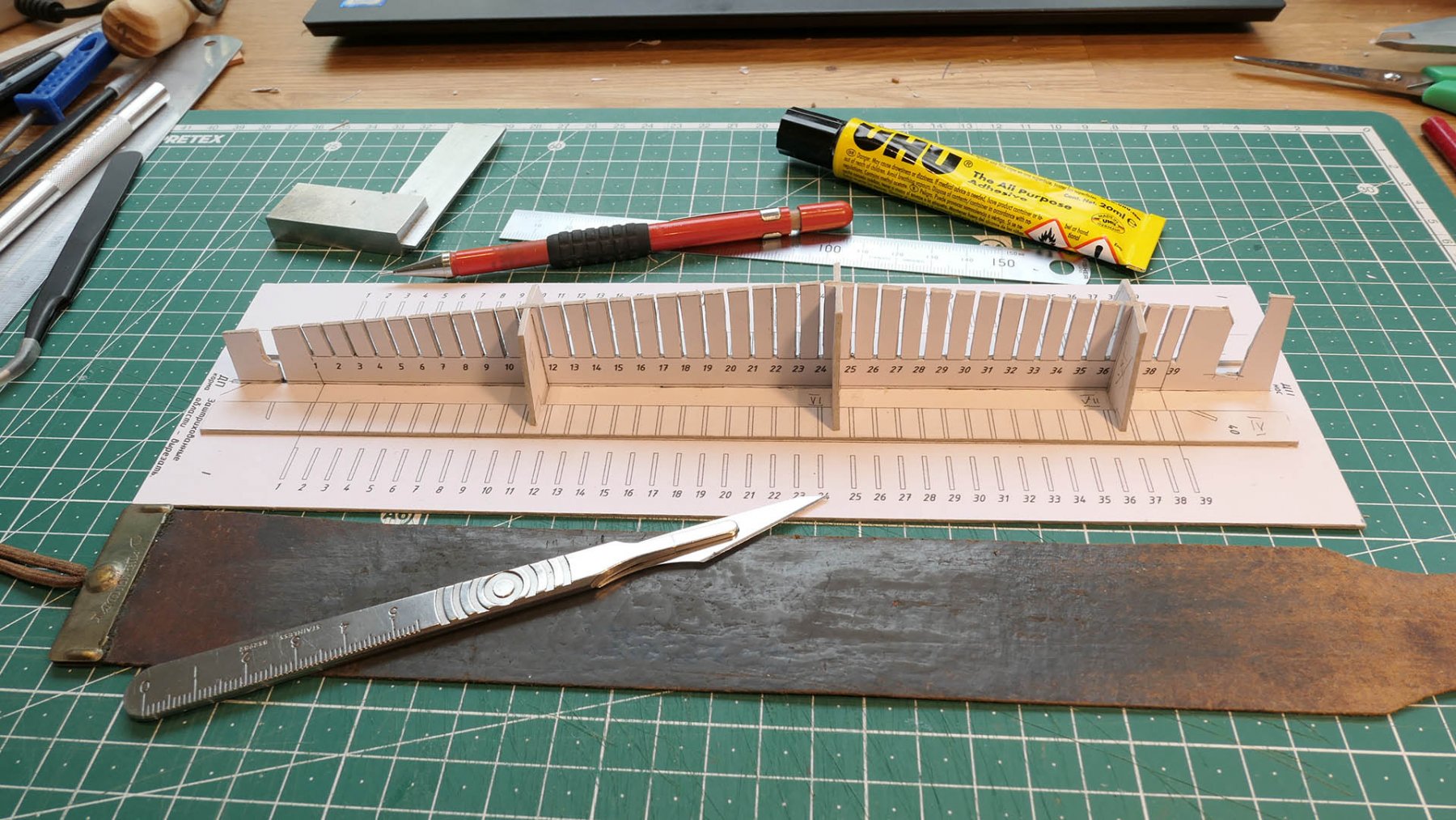


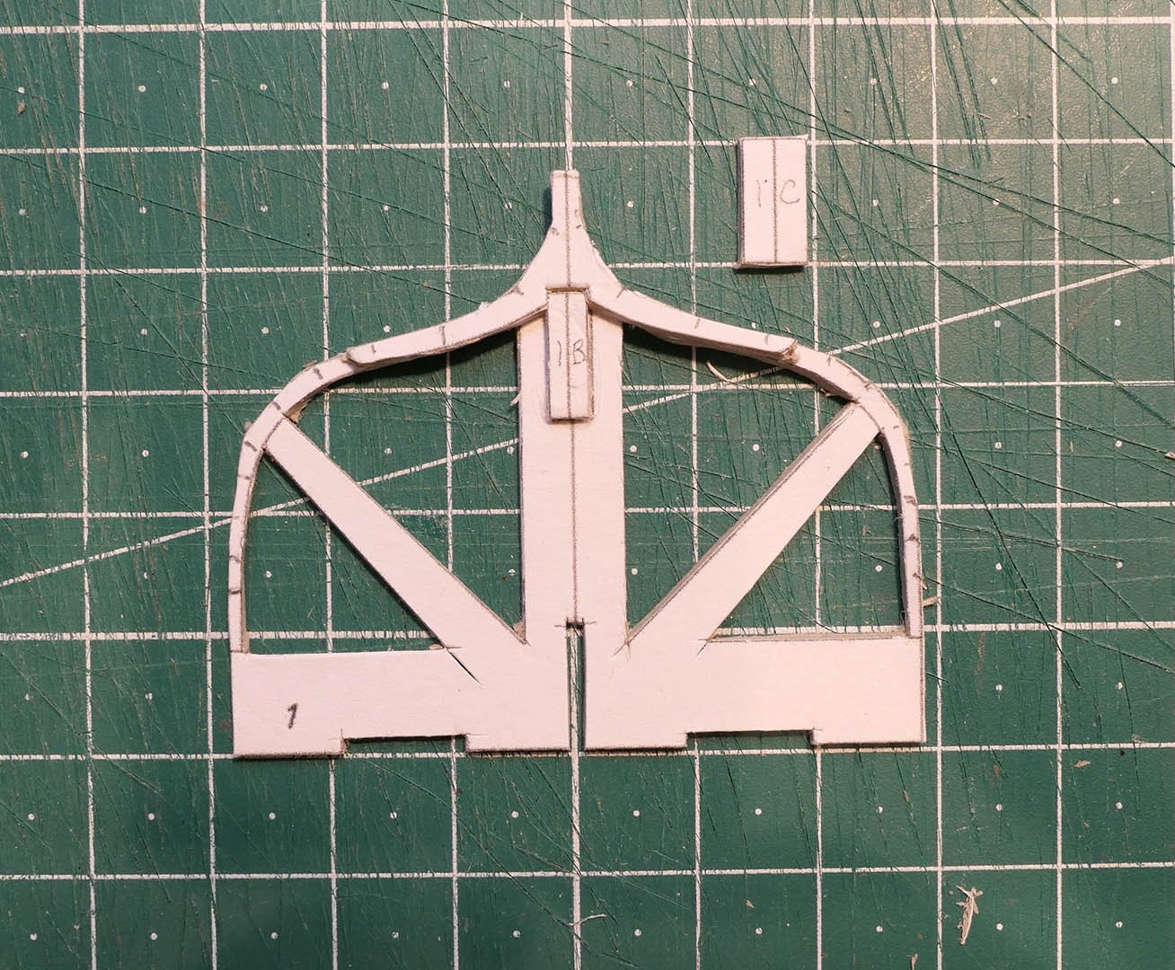
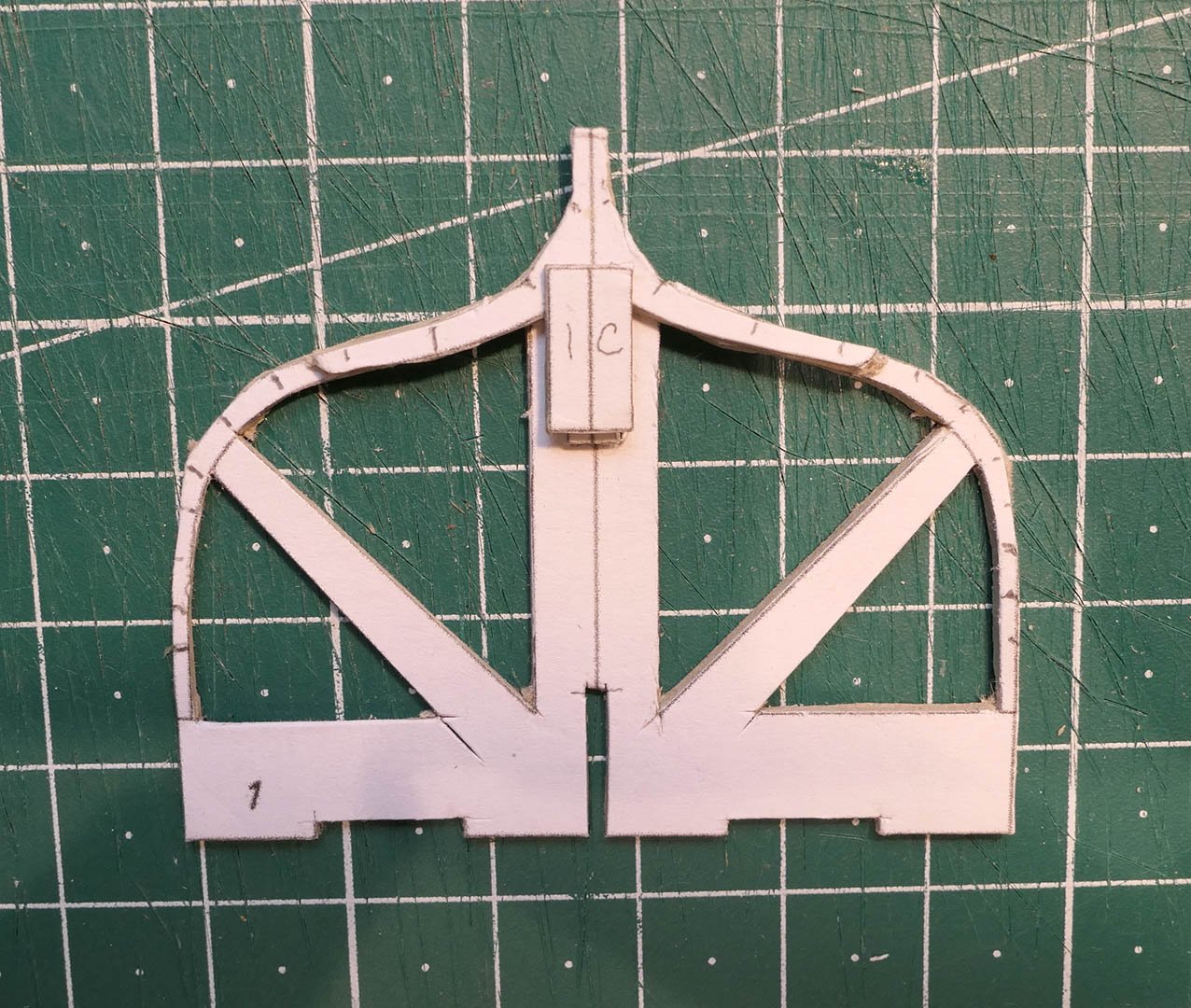
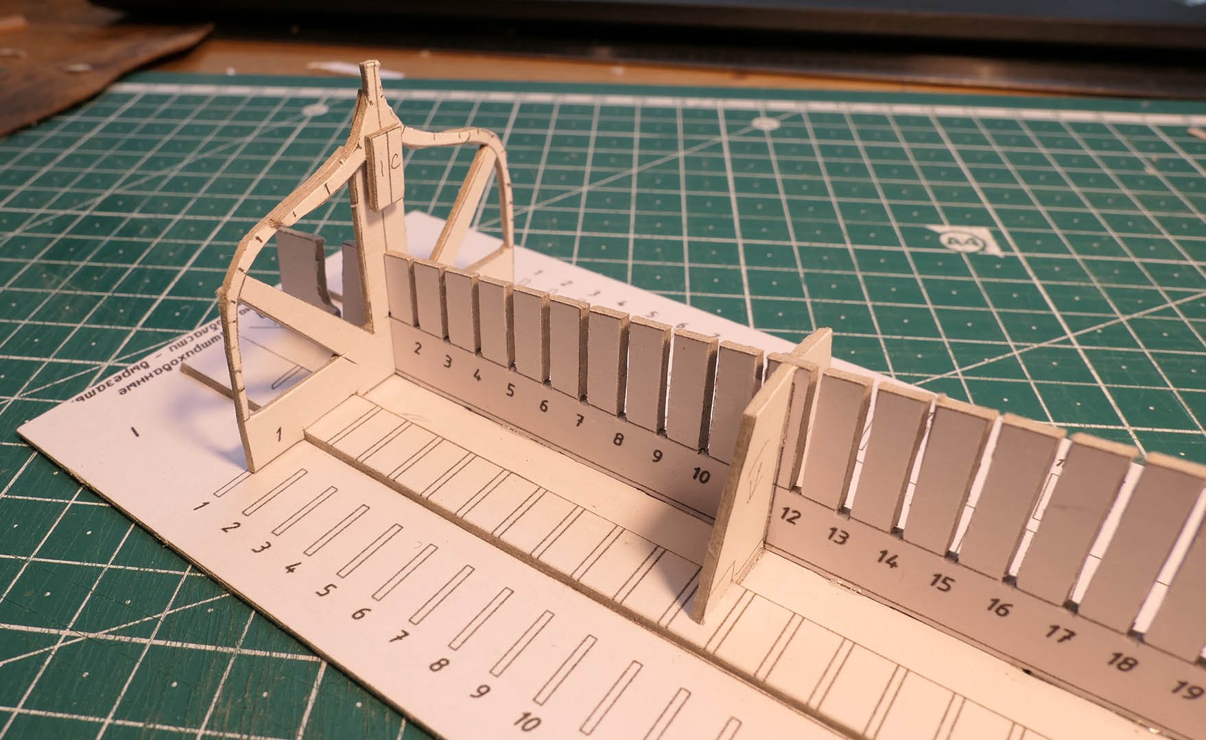
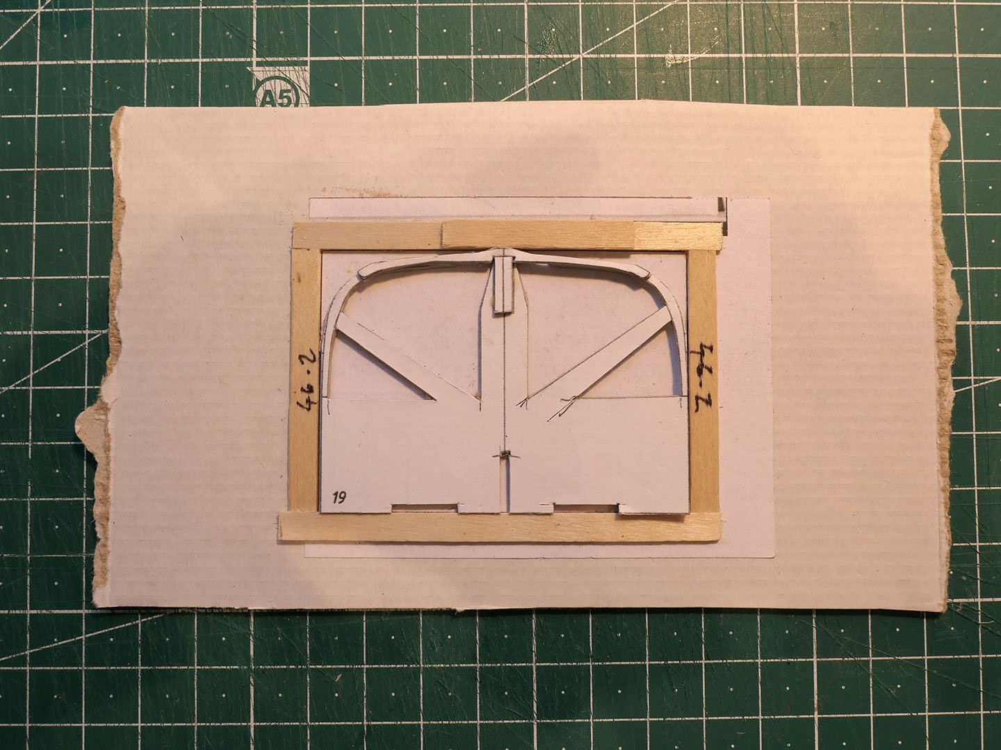


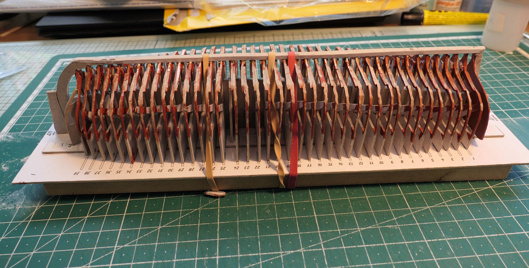

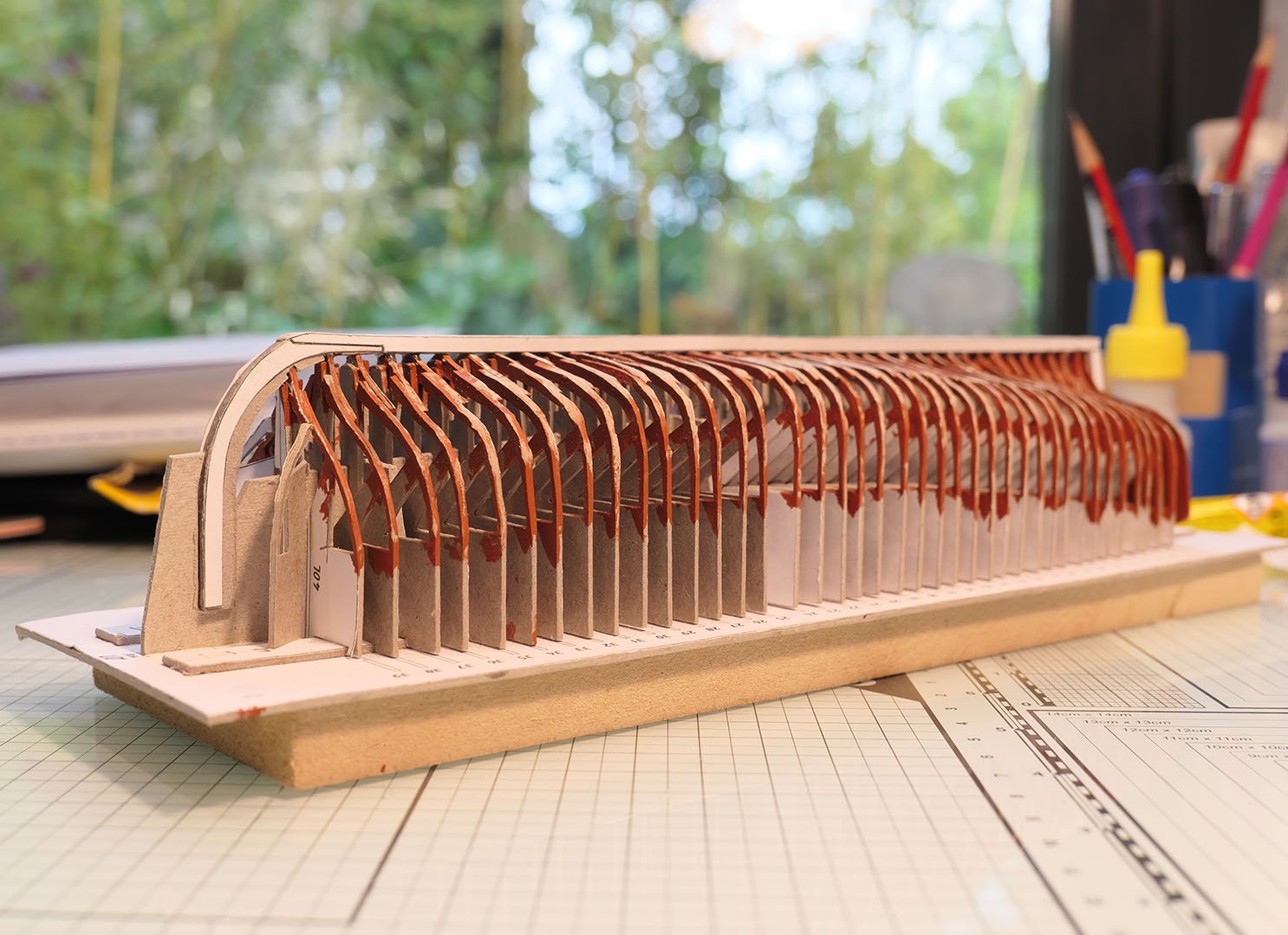
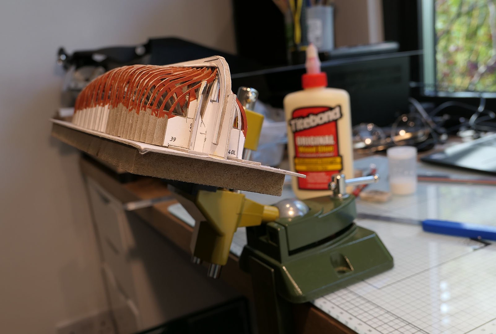

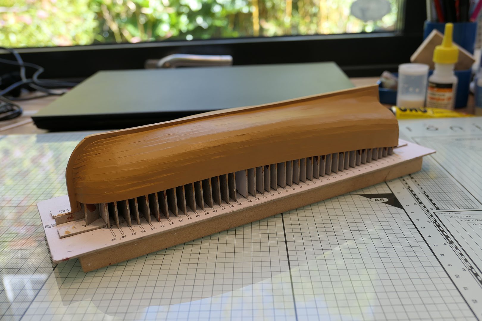


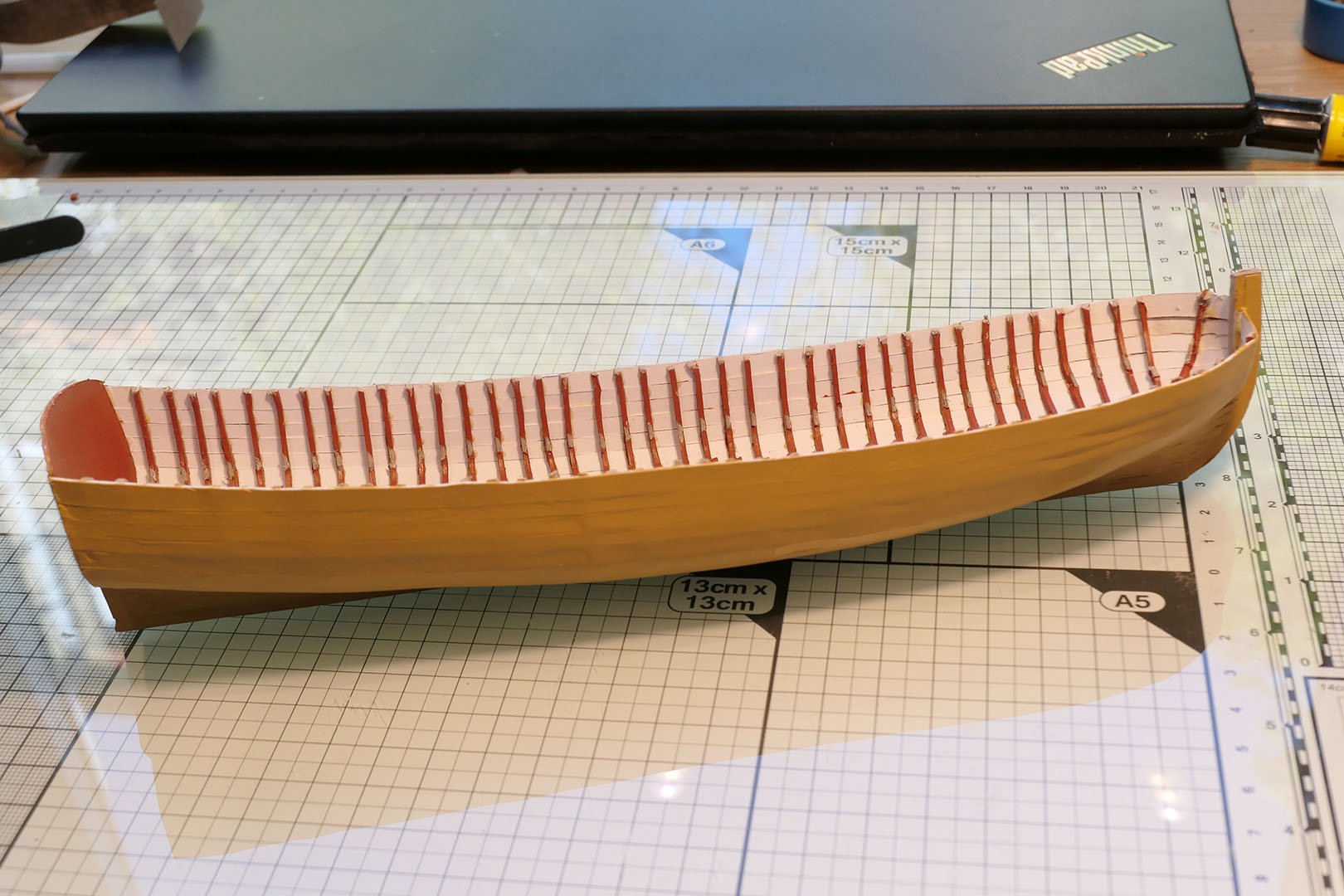
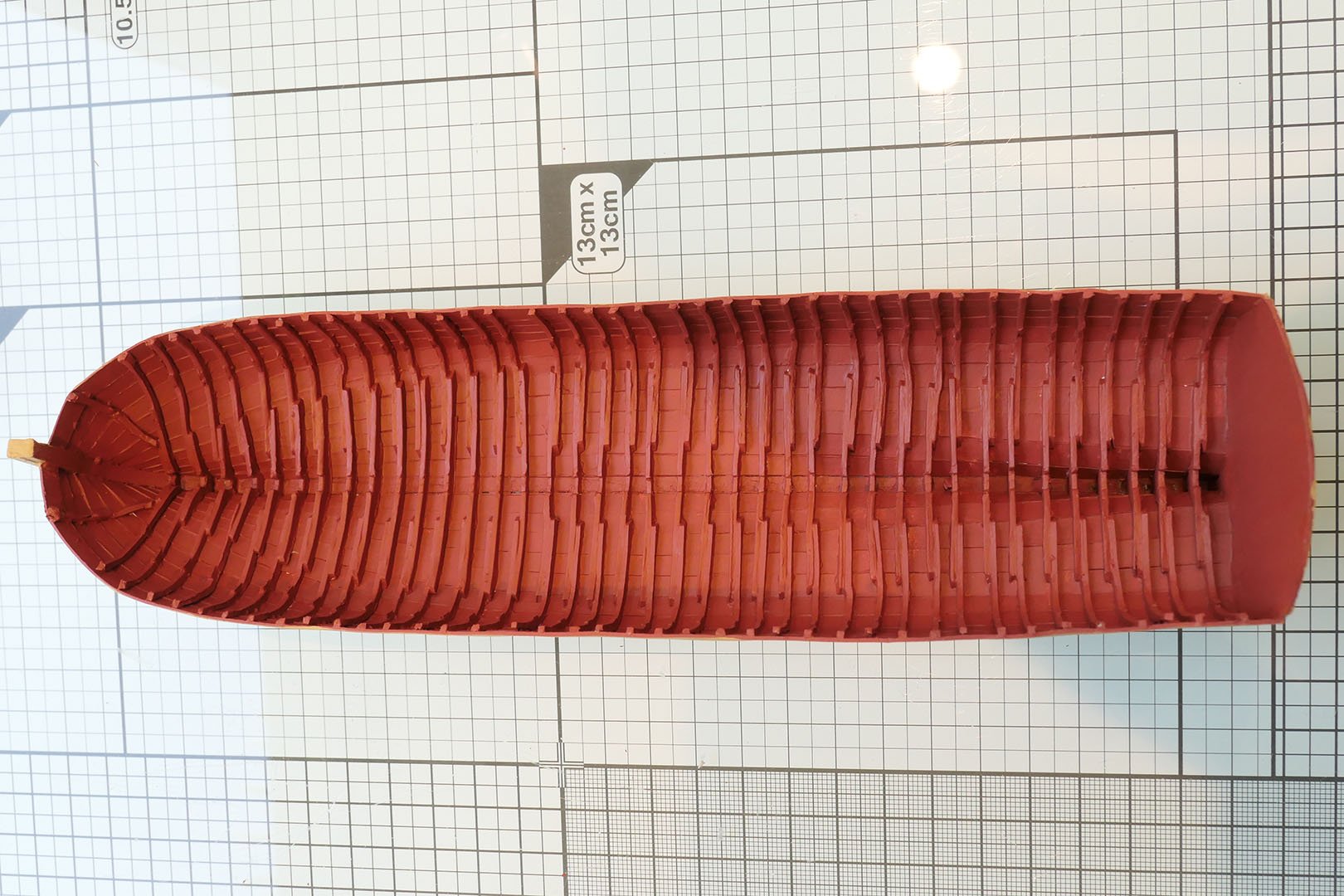
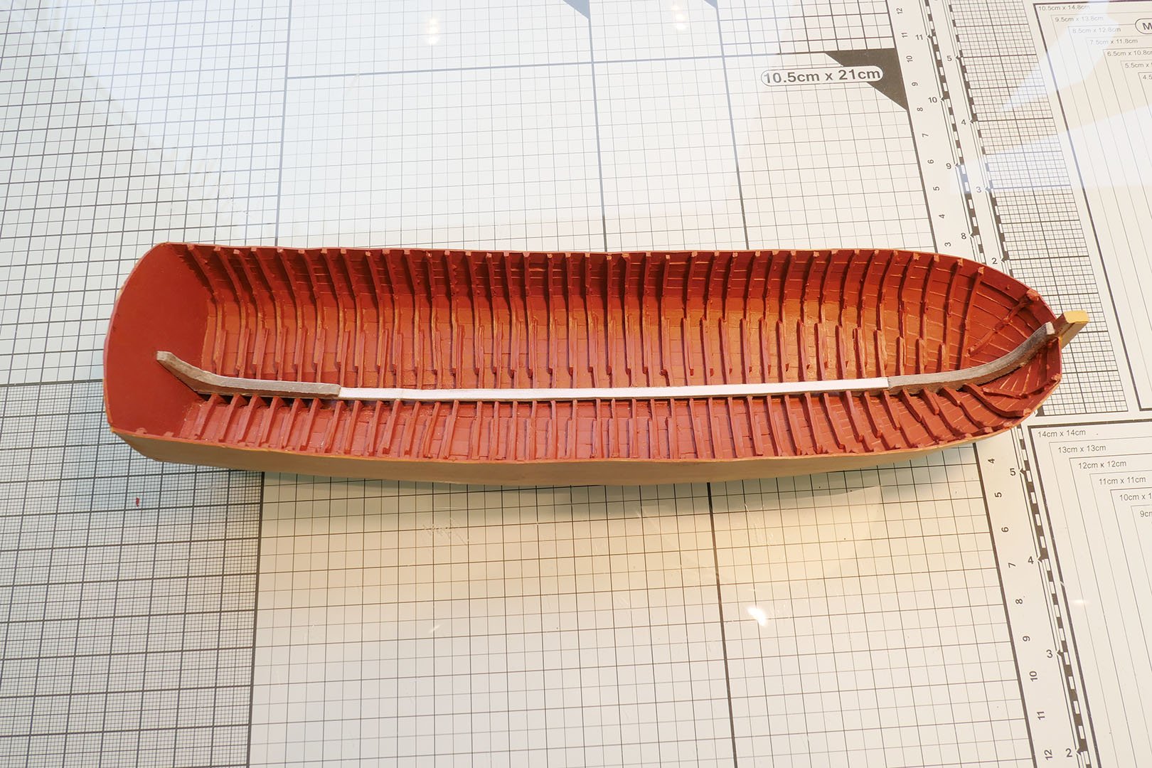
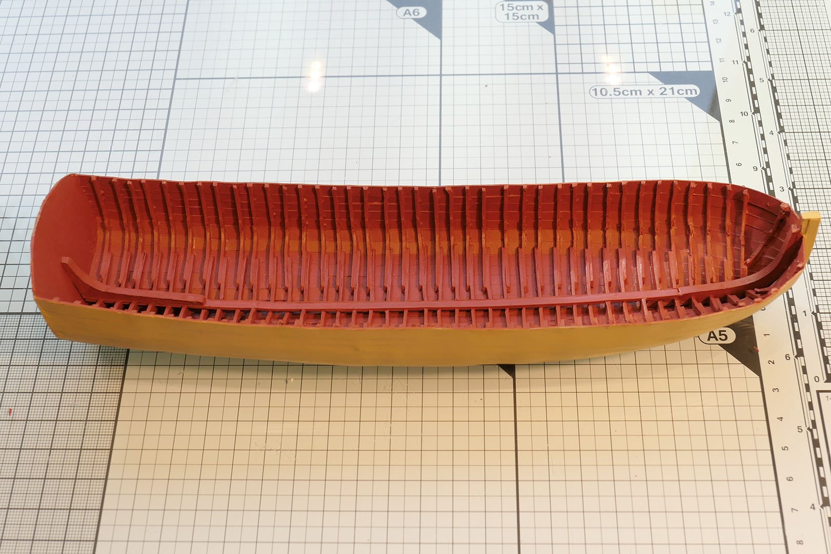
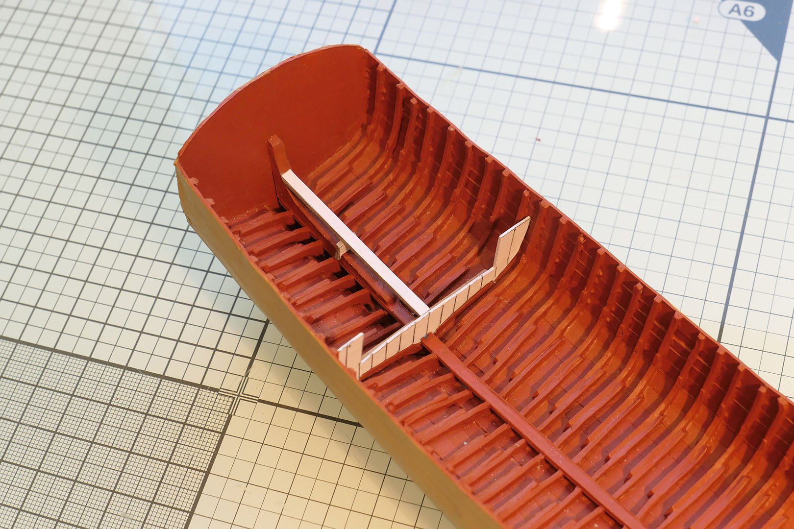
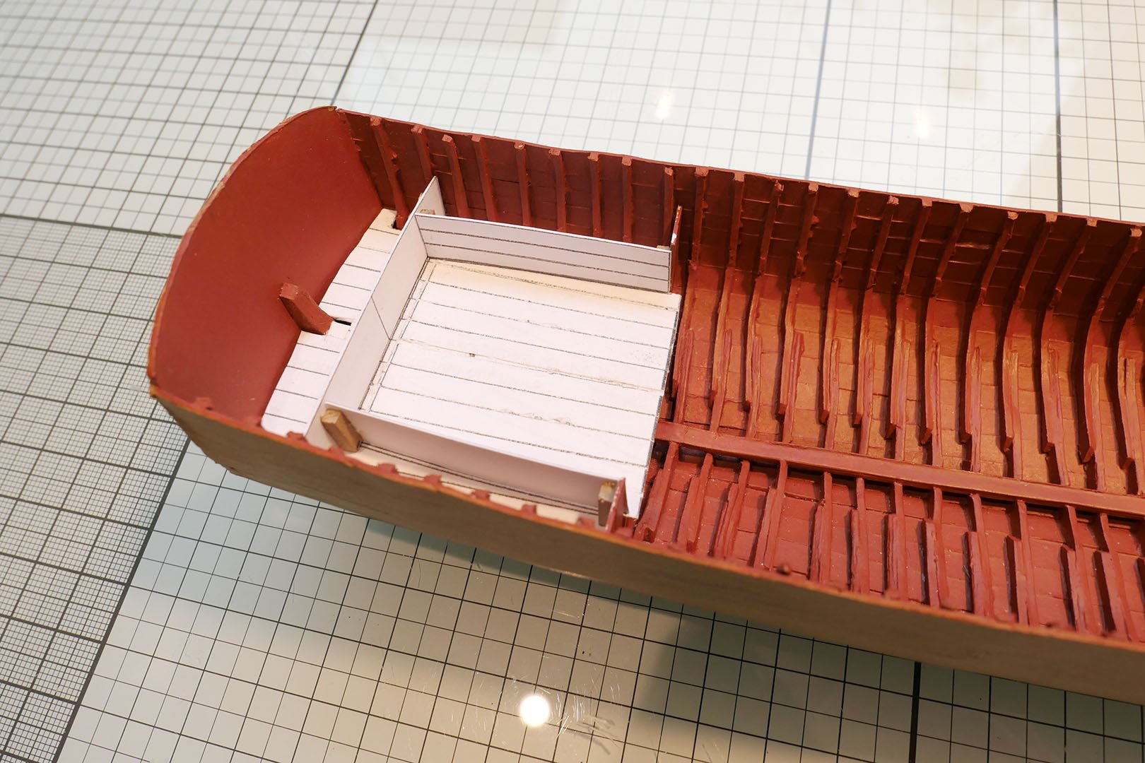


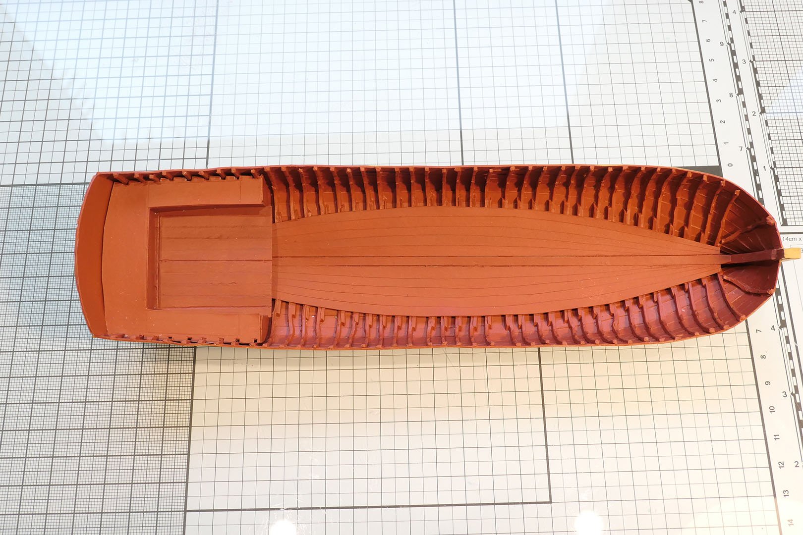
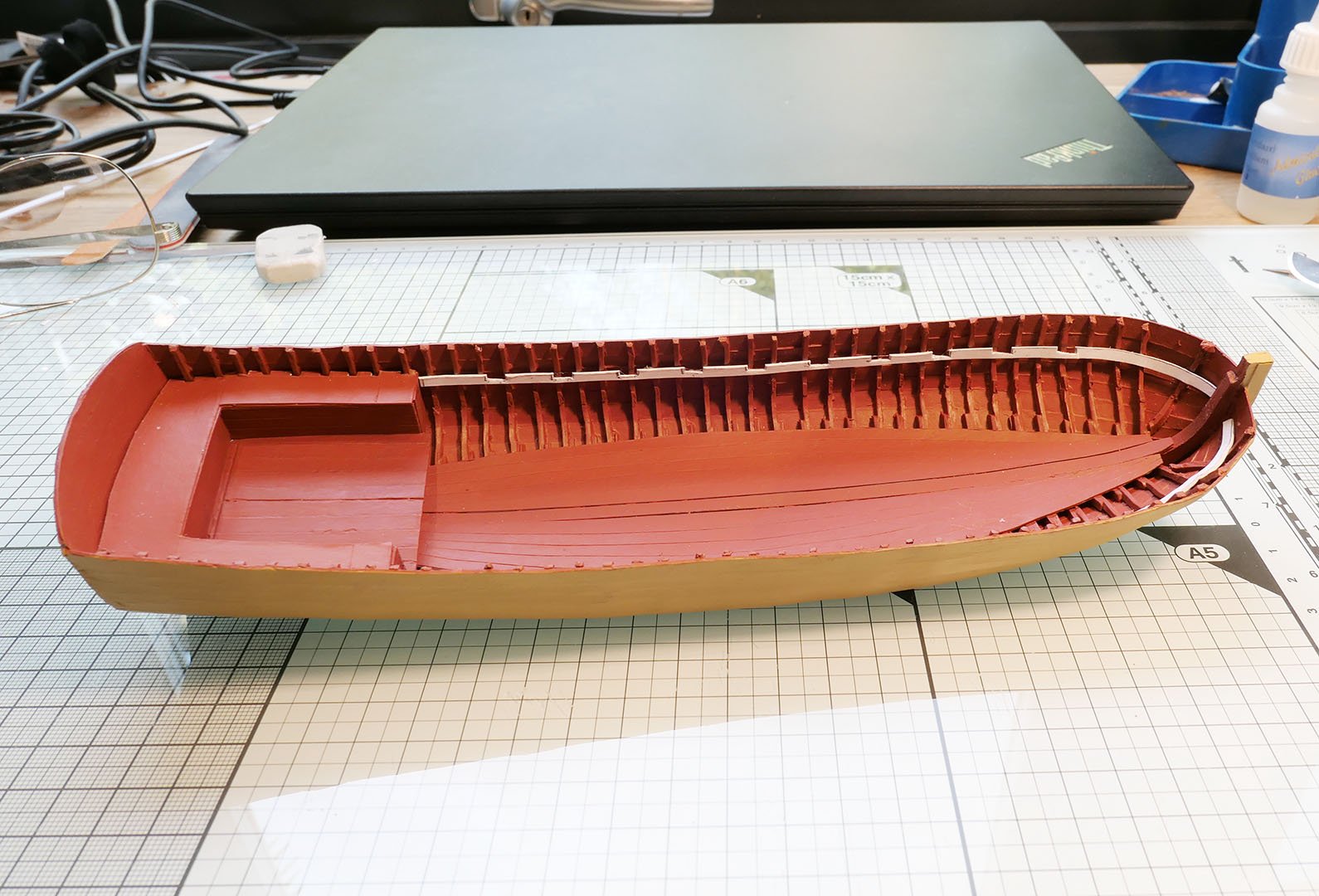
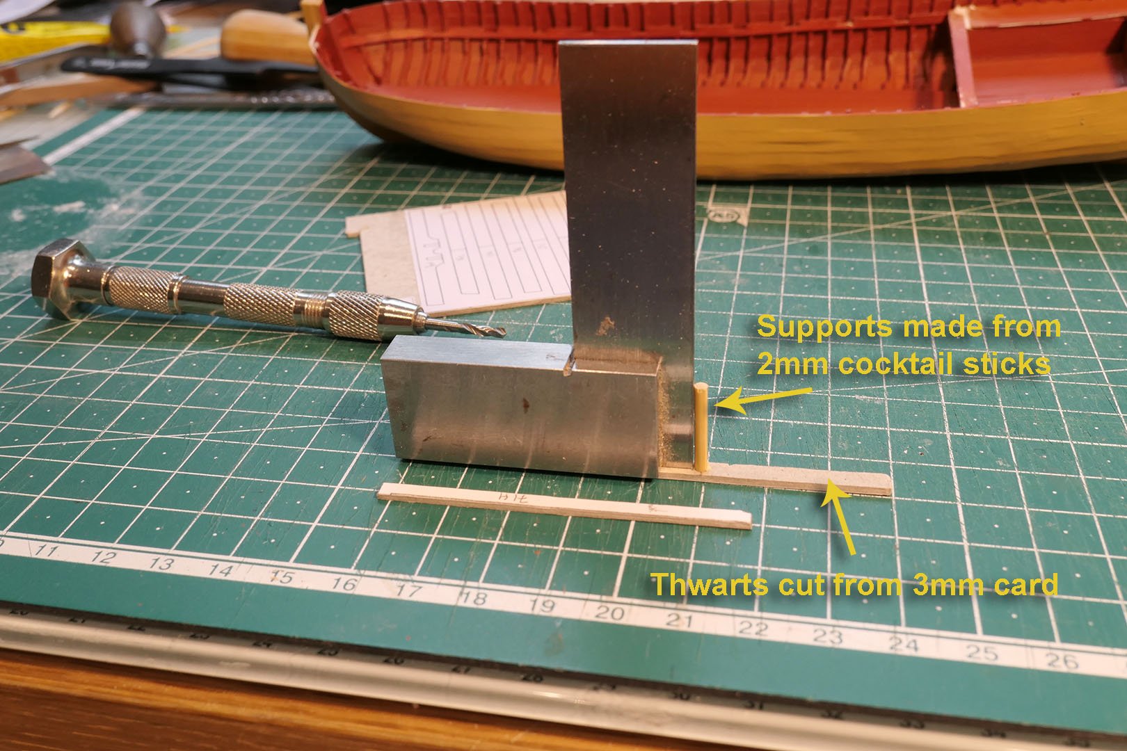

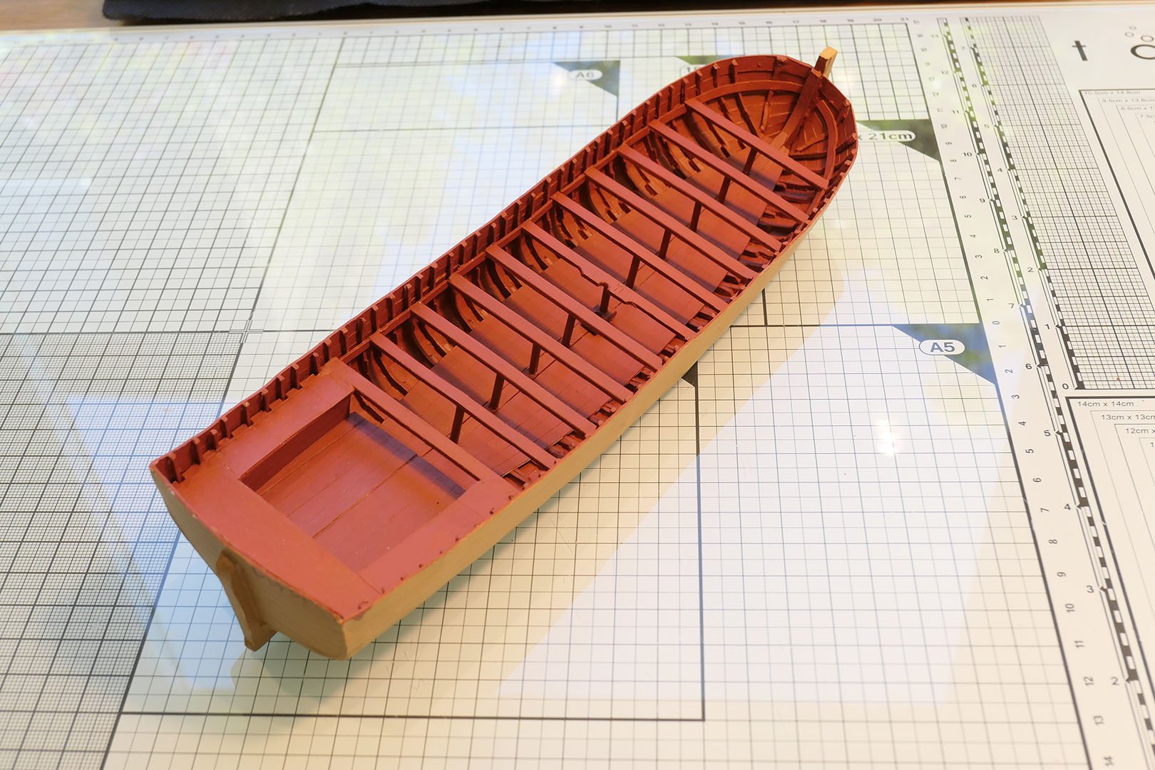

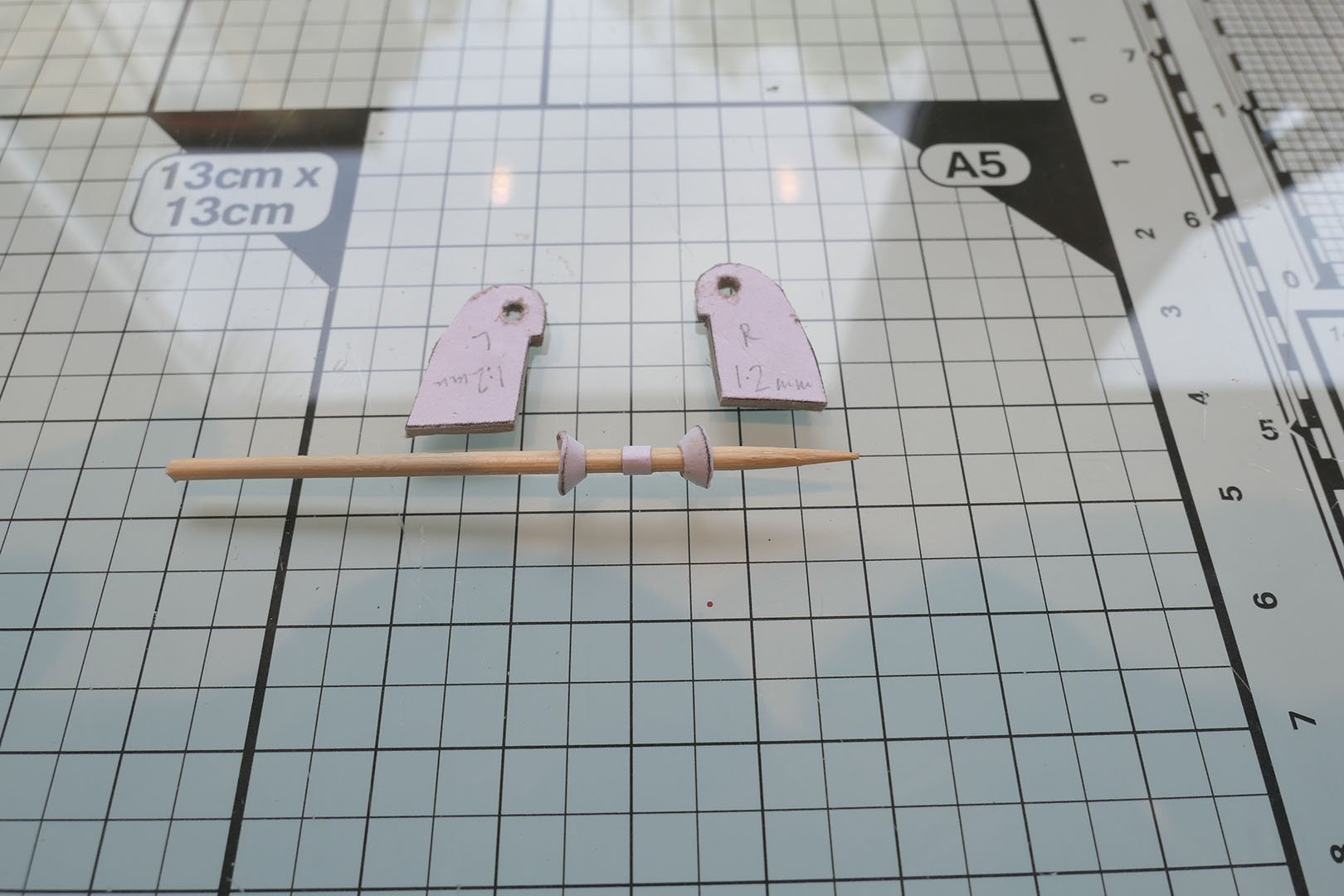
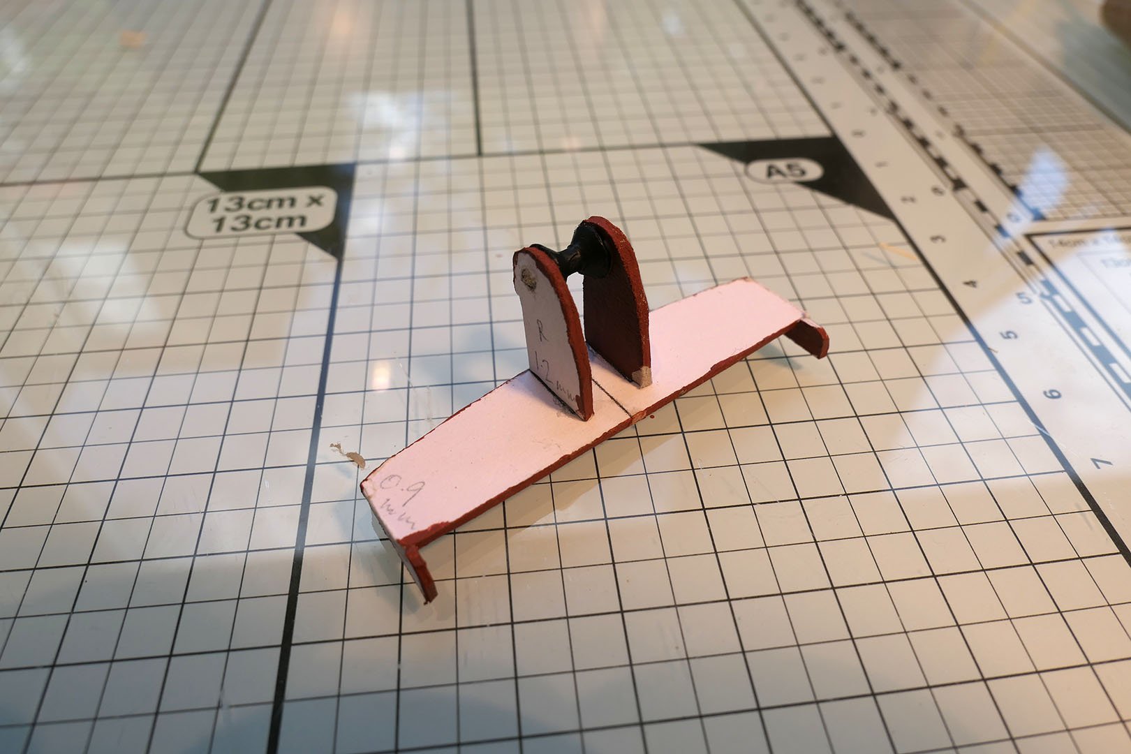
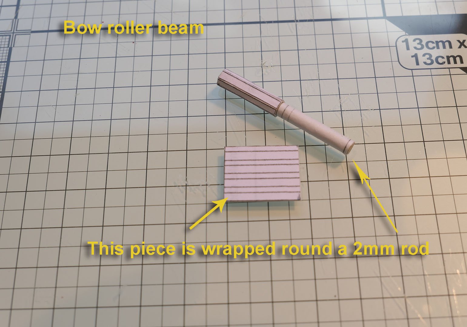


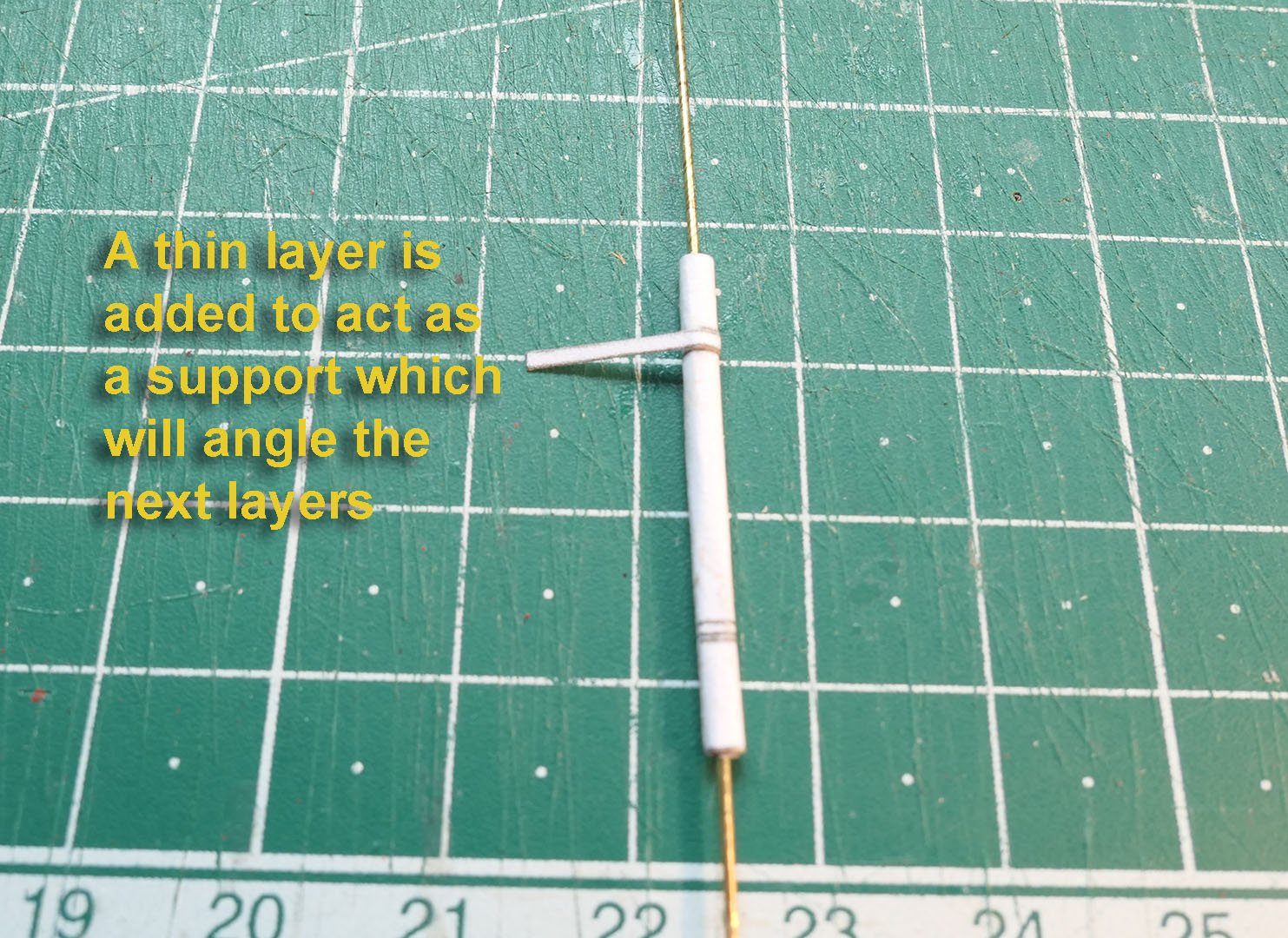

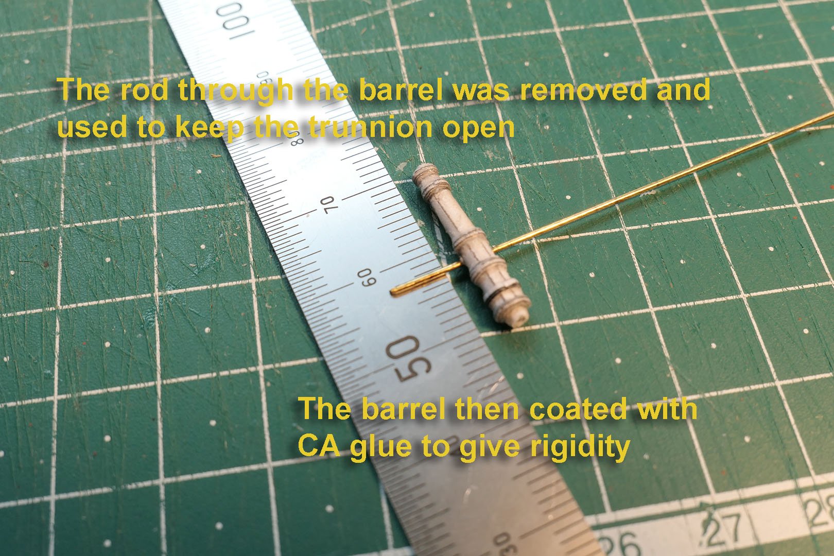

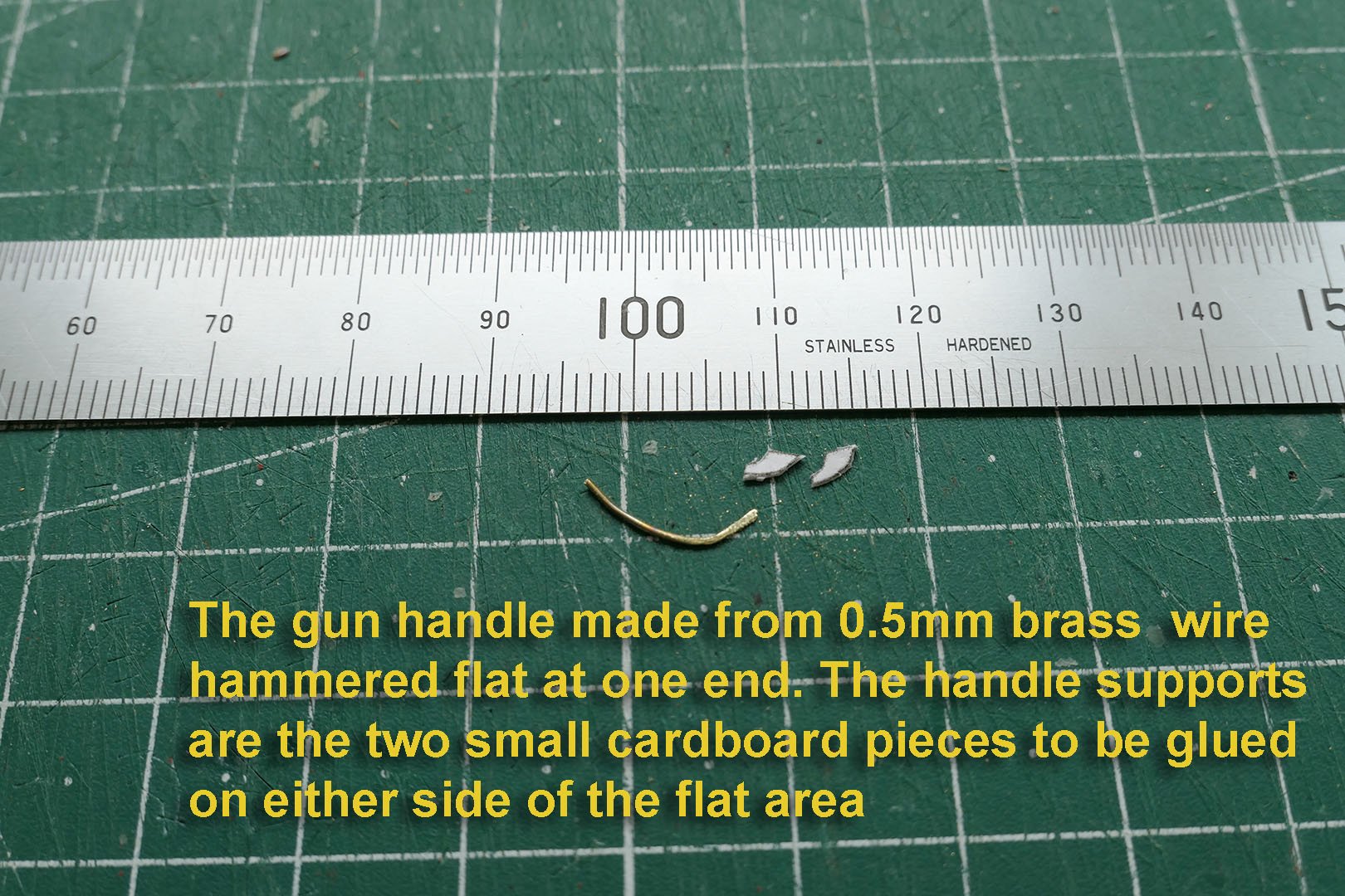

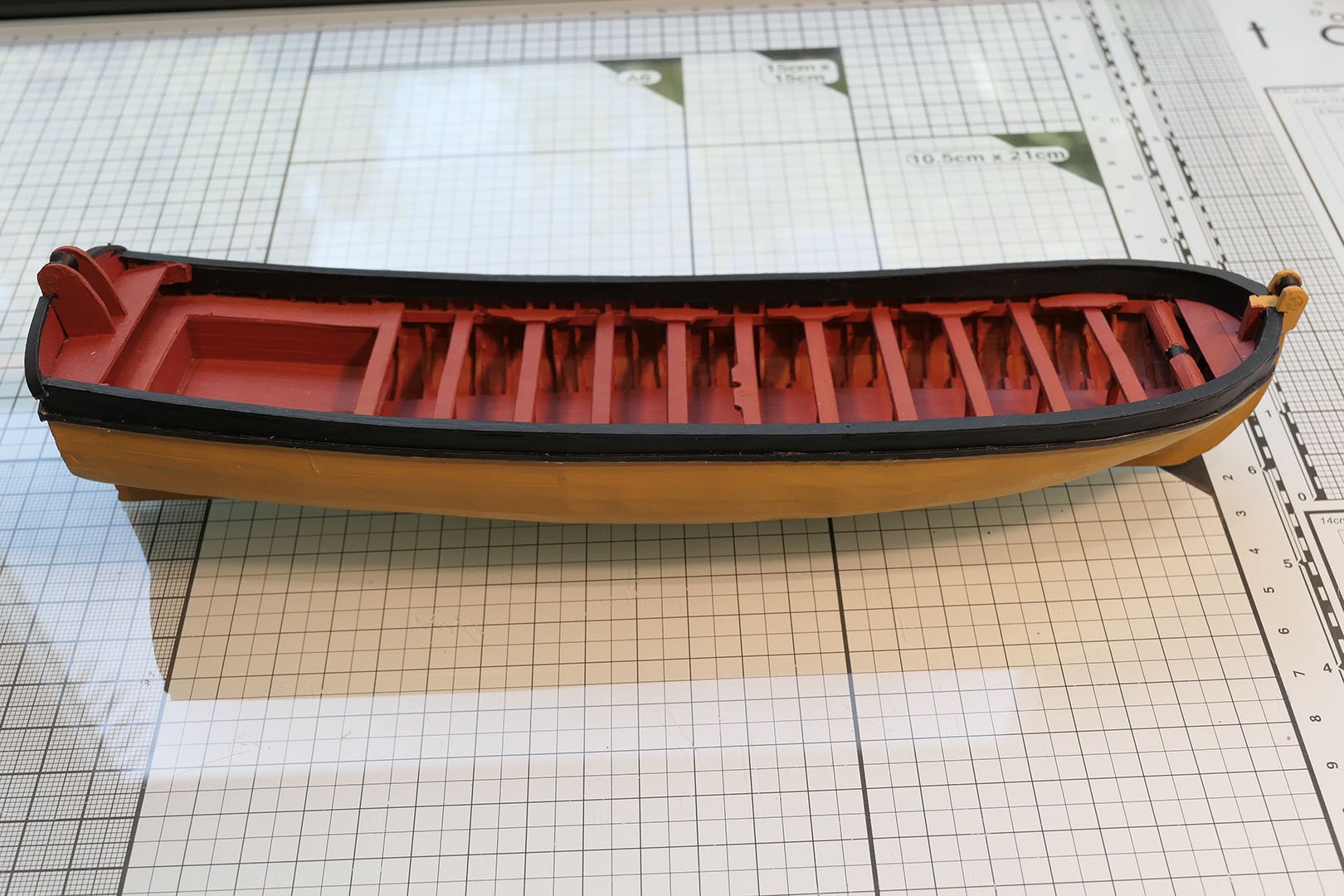


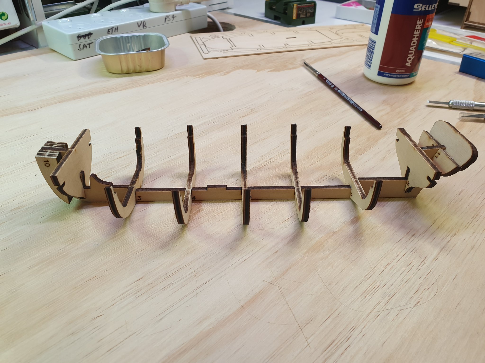
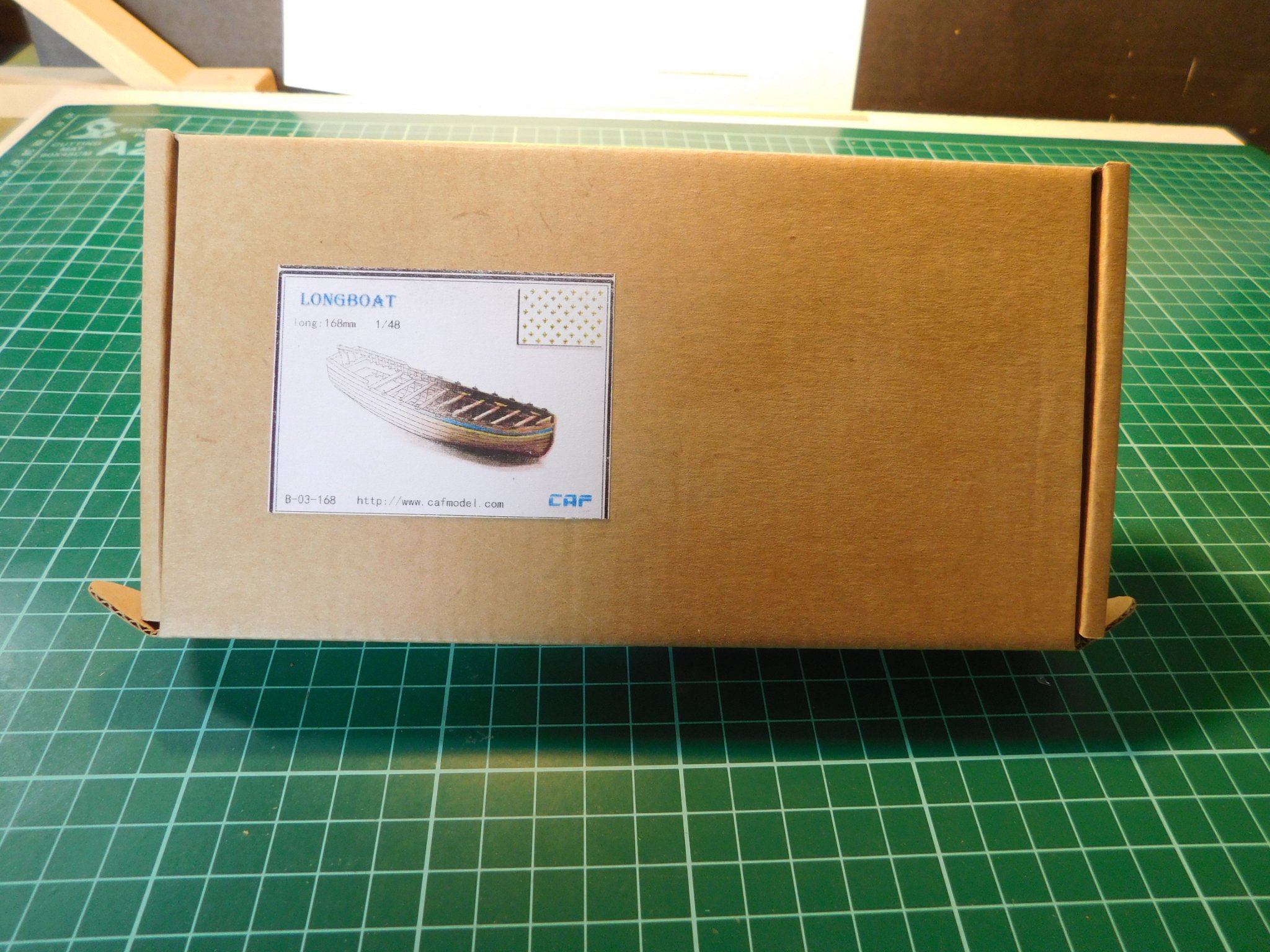

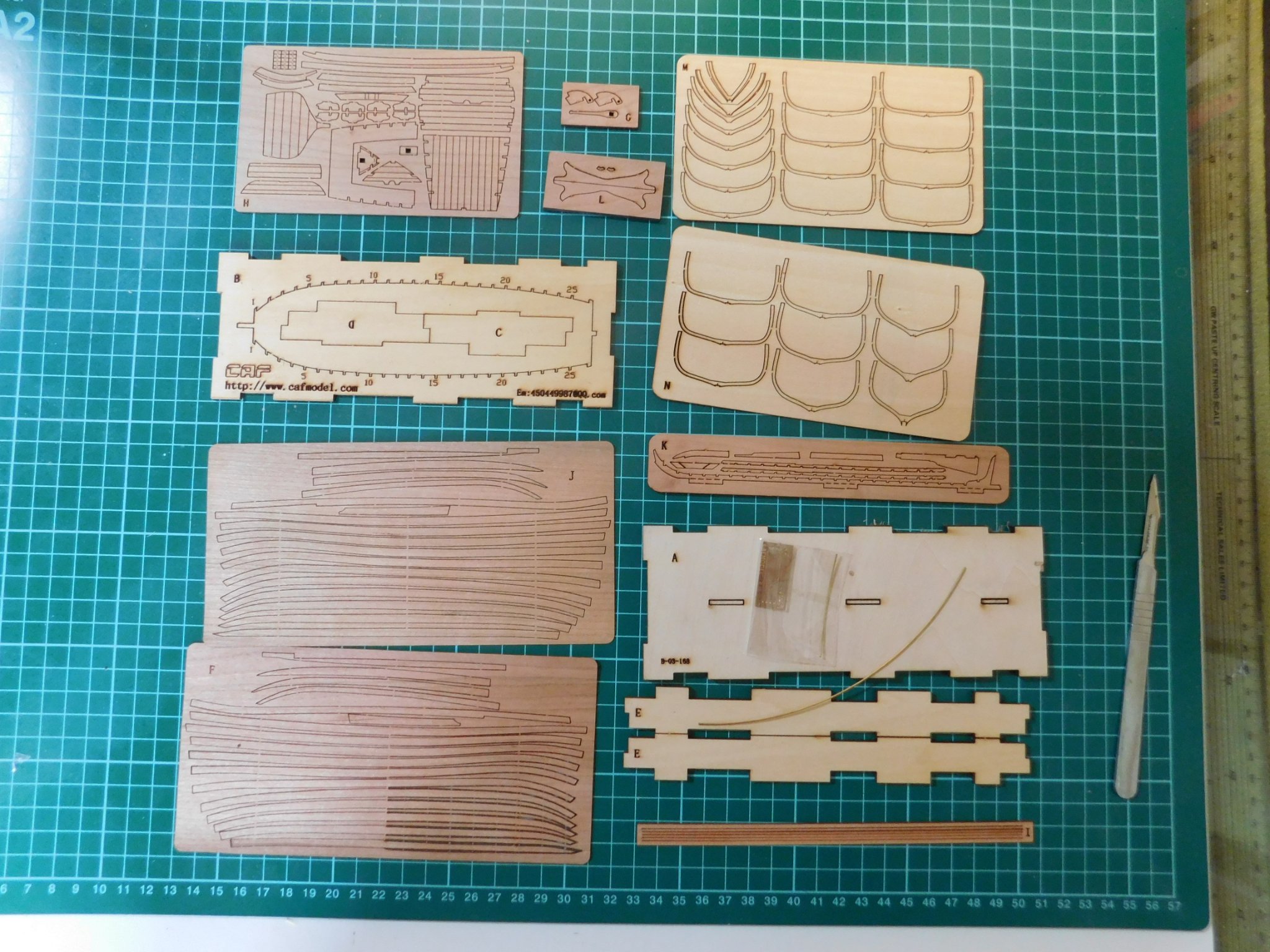


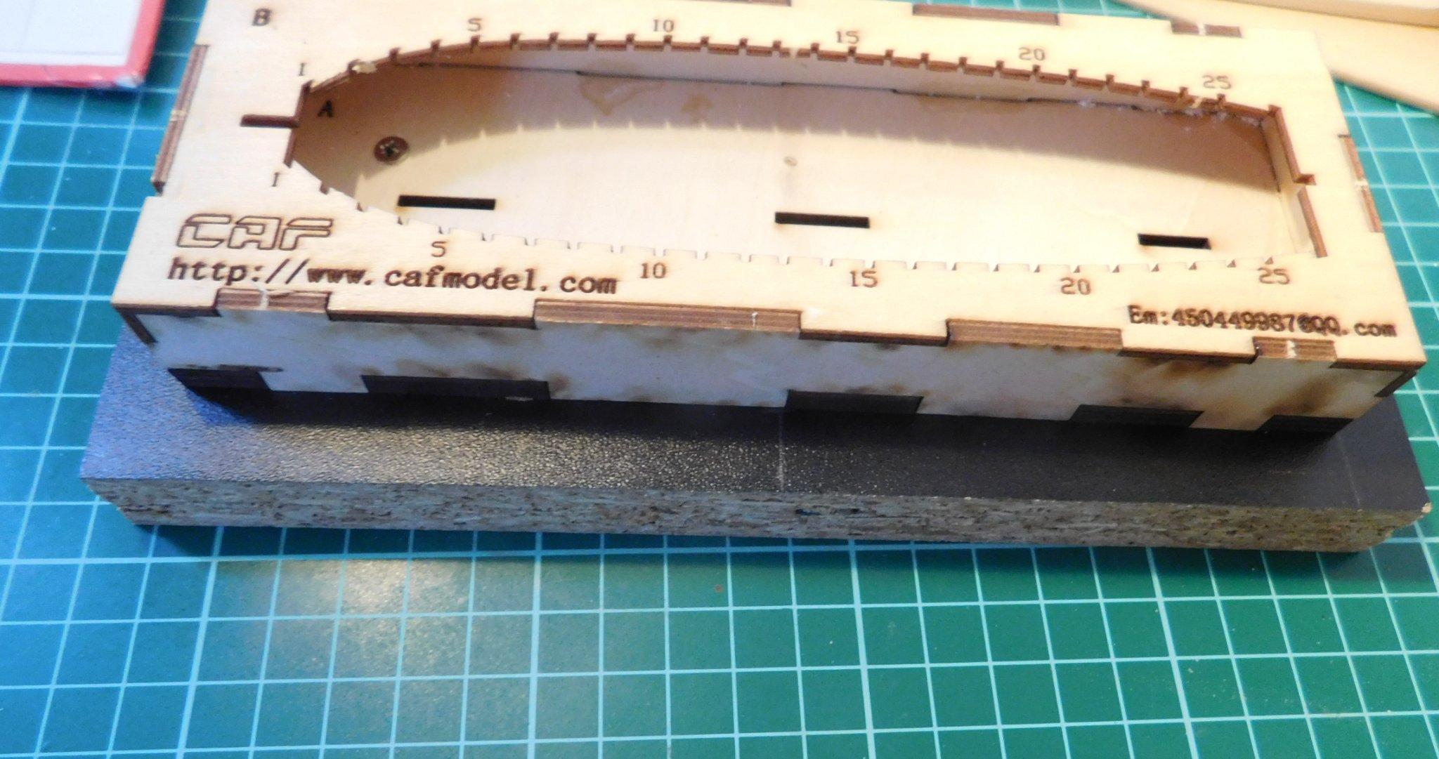


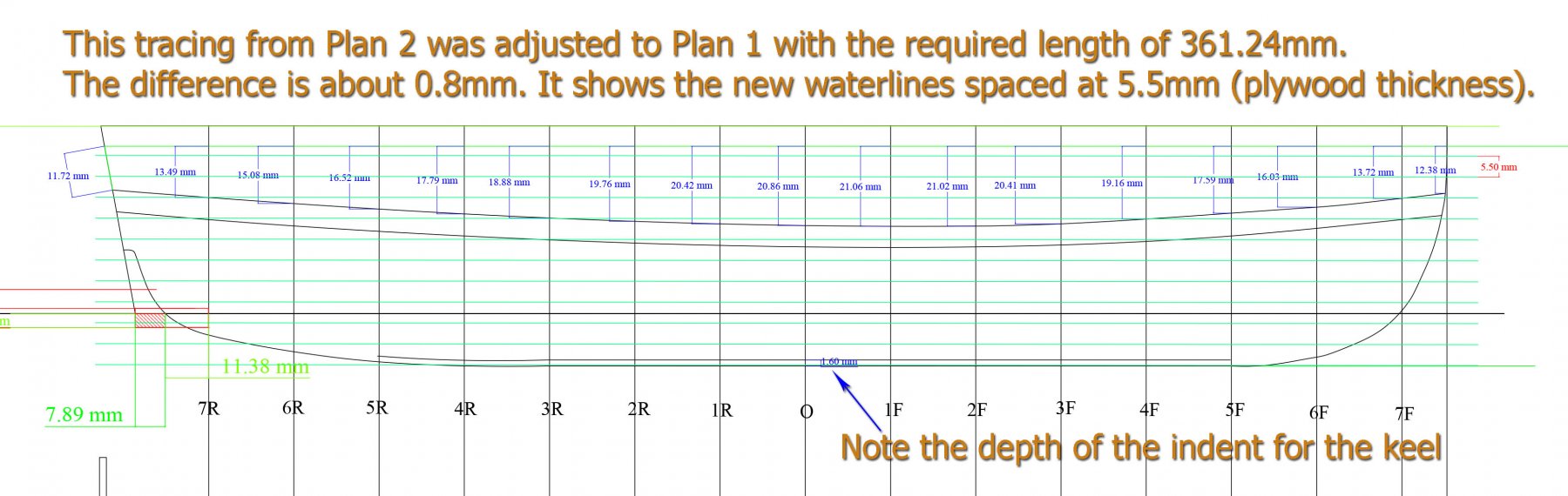
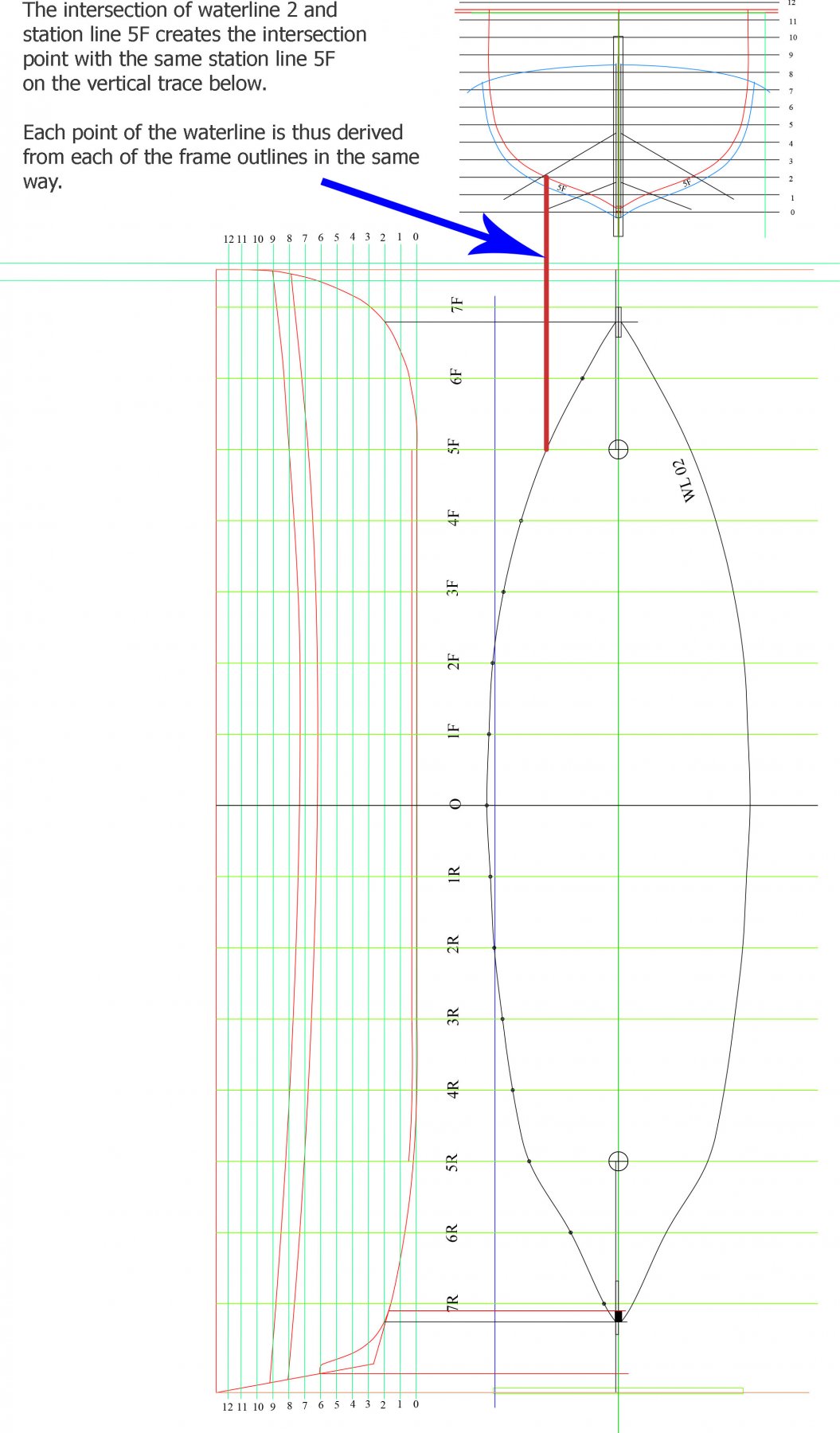
.jpg.a2b9b2e09b5ce45fcc2779b397dfe457.jpg)