Search the Community
Showing results for tags 'Masts'.
Found 17 results
-
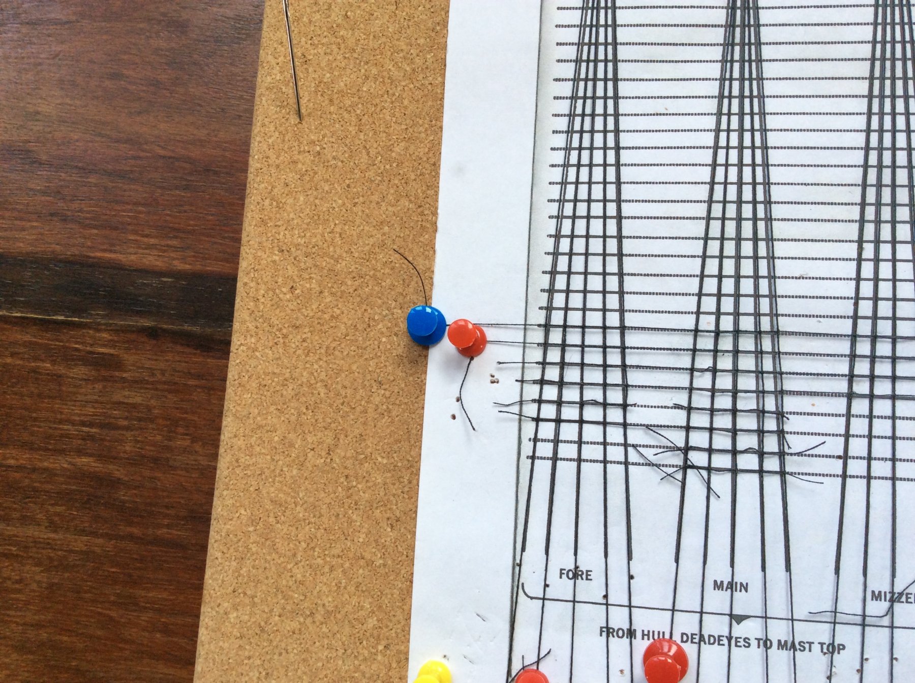
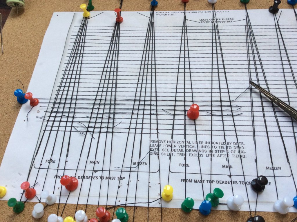
Hi all, I'm in the middle of building the Revell Cutty Sark. Have had the kit stored for about 15 years so thought it was about time to take it out of the box. Basic hull and mast construction is complete and though the colour scheme may not be true to life, many ships changed parts of their colour scheme during their service so I make no apologies. One of the worst aspects of the model is the amount of flash and the filing that has to be done to remove excess material - very time consuming. However, it's not too much of a problem to get the parts to fit. This brings me on to sequencing and here I think the instructions could be improved. For instance, I would do as much rigging work as possible before attaching the spars to the masts. Most of the Standing Rigging is in place including the Ratlines, a lot easier to do than working your way over and under the spars. Incidentally, the ratlines are all hand knotted and the way I did them, setting them up on a frame, prevents the "hourglass" shape which some folk have mentioned. You can see this in the pictures; I've used the template supplied with the model and stretched the vertical threads using map pins to hold in place. Then again using map pins to hold it in place, I start the horizontal threads with the tension maintained. This way, you can complete the ratlines for one side of the model just by working across the template, then repeat for the second side. I'm just about to start the sails and running rigging and would appreciate advice on whether to glue the yards to the masts and then attach the sails, blocks, etc.. Or attach the sails, blocks, and so on to the yards first, and then mount the sub-assembly to the mast. I reckon it would also be sensible to work from the deck upwards rather than top downwards. Any ideas welcome guys, thanks.

-
 Hi! I've been researching about masts for a while now and more or less understood how lower masts are constructed but I found little info explaining other masts. Can anyone explain the differences in construction, please? I'm particularly interested in 17th century frigates. I usually see topmasts without cheeks or bibbs. I'm not sure if these diagrams are correct but if then how trestle trees would be attached to the mast. Also, topgallant masts often feature head poles and I don't understand how these head poles are attached to the topgallant masts either.
 -
 While researching the mast lengths for my HMB Endeavour build I came across an online copy of David Steel's The Elements and Practice of Rigging and Seamanship 1794. Here is the link: http://www.hnsa.org/resources/manuals-documents/age-of-sail/the-elements-and-practice-of-rigging-and-seamanship/page-1/ I am finding this to be a great resource even though it is a later compilation from different sources (there are other formulas which varied between shipyard and country during that time) because it has helped answered the tough questions I was having regarding the mast lengths and their respective heights above deck and outboard, which are important to know for the model builder. But to work this out I first needed to know where each mast is stepped. Currently no plan has been found showing the mast steps and below deck stanchion bracings. I finally found the answer in the opening chapter of David Steel's Mast Making Vol.1 which clearly indicates that the fore and main mast's are stepped on the keelson while the mizzen mast is stepped (or more correctly can be) on the lower deck. From this discussion we have located other sources which independently support stepping mizzen masts in the lower deck. The stepping of mizzen standing masts in the lower deck is also supported in William Mountaine 1761 'The Seaman's Vada-mecum and defensive war by sea', and other NMM ship plans prior the 1764 construction of Bark Endeavour. Working back from the 1771 Woolwich Yard mast measurements I found one set of Steel's formula to give me a very close match to these measurements as there are several formulas to choose from but only one set that appears to fit. Remembering that in 1764 ship building was still an evolving art which varied between country's and ship yards while Steel's work didn't come out until 1794, 30 years later. Given this time lag I think it is reasonable for there to be some lee way in interpretation and use of these formulas. With this in mind here is my math: Main Mast (whole length): Wooldwich Yard 69',4". Formula: L = Length, B = Breadth, L+B/2 To get this to work I've assumed L to be the measurement from stem to stern instead of the gun deck which Steel uses. The gun deck could could have become the standard in 1794 but might not have been in 1764. L @ 109' (approx) + B @ 29',2" divided by 2 = 69' (very close to Woolwich @ 69',4"). Stepped on the keelson @ 20',6" below the quarterdeck. 69',4" - 20',6" = 48',8" height above quarterdeck partners. Foremast: 8/9 of mainmast = 61',6". Woolwich Yard 65',4". Woolwich measurements are in yards @ 21yards, 28inches which would bring the foremast to almost the same height above the waterline as the mainmast and giving it a height of 47',4" above it's partners on the forecastle. (I have since revised this and the foremast looks to be close to within normal ranges at 65'4" compared to the main mast making it's cap around 2.5 feet below that of the main mast cap). Mizzen mast: 3/4 of mainmast = 51',11". Woolwich Yard 50',5". Stepped in the lower deck @ 12',6" below the quarterdeck gives a height of 38' above it's quarterdeck partners making it's cap around 8' below the main mast cap (within so called 'normal ranges') Bowsprit: (whole length) 3/7 of mainmast = 29',8". Woolwich Yard 34'. This does not match until we work out the outboard length which is 3/4 of 29',8" = 22',4". Considering where the bowsprit is stepped in the fore topsail sheet bits then @ 34' it achieves this outboard length of 22',4". The contemporary evidence critically examined in this discussion reasonably and logically supports that the 1771 Woolwich Yard measurements are accurate to within reason. The critical missing peace of the puzzle was that the mizzen might have been stepped in the lower deck and not the keelson as suggest by some late 20th century research. I almost missed this myself until I later searched for it as I realized with out this information I couldn't make sense of the Woolwich yard measurements because stepping the mizzen on the keelson at that length just wasn't meeting up with the angle of the mizzen chainplates from the as fitted draught of 1768. And would make the Mizzen cap 18' feet lower than the Main cap which just isn't the case in contemporary drawings and paintings attributed to Sydney Parkinson from Cook's voyage and nor is it within a so called 'normal range'. Where as stepping the 50'5" Mizzen in the lower deck brings it's cap up by 10' to within this normal range. I apologize for any inaccuracies.
- 63 replies
-
- 3
-

-
- HMB Endeavour mast lengths
- above deck mast heights
- (and 3 more)
-
 I find myself continually bumping up against my ignorance. I feel pretty good about getting my masts assembled to be straight. Now I'm adding the various blocks that will be part of the running rigging. There are a number of blocks - see picture below - that are attached to the one mast or the other between the cross trees and the cap. I cannot make out what knot to use to properly attach those blocks to the mast. Can I please get some advise on how to rig these blocks in an authentic way? Thanks, Rich Klecker
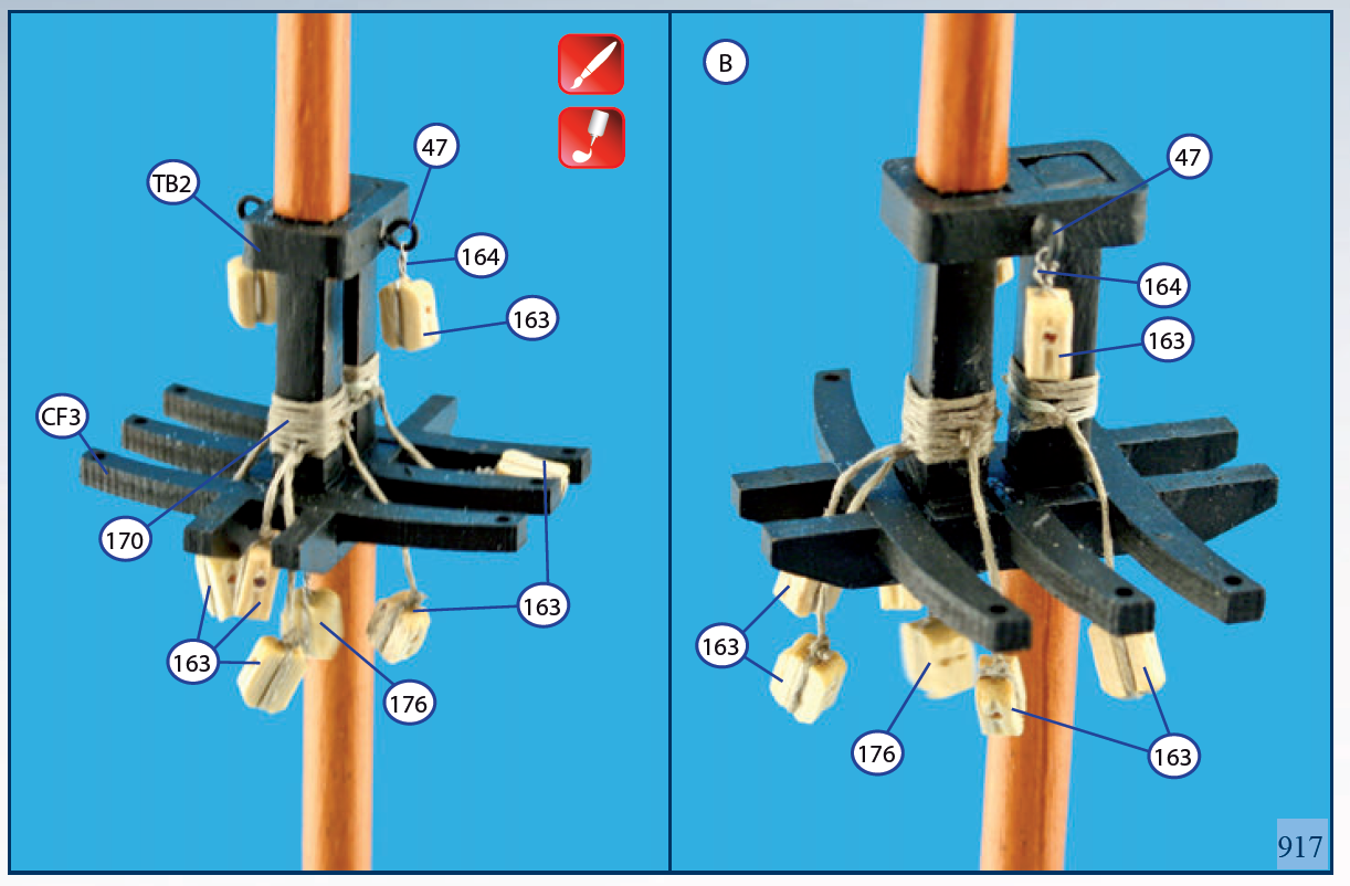
-
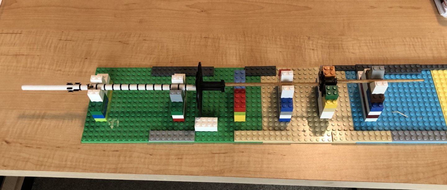
I posted a question a few days ago about alignment of stepped masts. I got several good replies but I still felt like I need something more. A visit with my five-year-old grandson gave me the inspiration I needed. LEGO! They are nearly infinitely adjustable, supply a stable and rectilinear base, and my grandson has approximately a million of them. Anyway, a picture is worth a thousand words. Here's the main mast of my L'Hermione just about finished up.
-
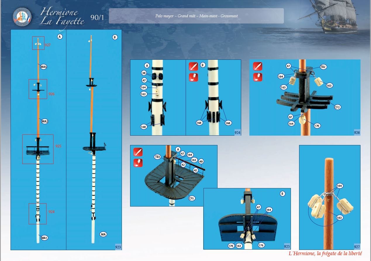
After many months I am now at the point of putting masts on the model and I can't make myself get started. I'm building AL's L'Hermione. I have cut and tapered the masts, they're painted and some of the blocks are installed. The AL instructions for this portion of the build are very abbreviated - read just pictures, no descriptions at all. The picture show the details for the individual masts and then it shows the masts assembled and ready to be placed into the hull. As I think about how I would assemble an entire mast I begin to wonder how that mast can be built to be straight and the individual masts properly aligned with each other. I've searched through the many contributions on this and related topics. It seems like there is a strong preference by many to install individual masts, attach the relevant standing rigging and then move up the mast; mast, then top mast, then topgallant mast. My concern with this approach is that as you work up the mast assembly you start working "in the air" with fewer and fewer reference points regarding alignment and plumb. Can I please get some help or guidance about how to proceed here. I need a push. Thanks
-
 Hello all, Just recently joined this excellent ModelShipWorld website and have a 'beginner's question'. I'm about to start the masts and rigging on my Dallas 1815 Cutter (my first build) and I recall reading somewhere that it can be a good idea to make a dummy deck first. The idea being to put the masts on the dummy deck (plank of wood) and do all the rigging etc on it, and then transfer the lot to the real deck. That would prevent accidental damage to fittings etc on the real deck whilst I fumbled about with rigging. Or should I just 'get on with it' and put the masts straight into the real deck and do the rigging there? Any thoughts? Regards and thanks, Richard
 -
I have the usual suspect textbooks: Lee, Marquardt, Zu Mondfeld, Davis. They have mast and yard length and diameter formulae for a number of nations but not Spain (except for Zu Mondfeld but his information is prior to the Napoleonic era and so not helpful .... Spanish spar formula probably changed with the surveyor). With the exception of the periods when the Spanish used English or French methods, is there a source of these formula? My books in Spanish, which I do not naturally read, all appear to provide information on Spars for actual ships (Frigate and above) and that just won't help me mast a brig though I do intend to work backwards and create formula that might be relevant to a brig. On the subject, a general book with Spanish plank sizes, hammock stancions, etc. would really help as well. I have several books by Enrique Garcia-Torralba Perez, books of photos of Museum ships, and a lot of original Royal plans and diagrams (many of which appear in said books as well), so that is how I have been picking up details but I really miss having sources like Goodwin and Lee. TYVM in advance!
-
I am looking for a source of approx. 0.4 mm thickness swiss pear (or similar flexibility timber) to create 1 mm. wide strips to form the hoops that were placed either side of a mast woolding. Just maybe there are other timbers that I could use but my knowledge of flexibility is meagre ? I do not have a thickness sander or similar exotic machinery so I need to purchase said thickness. Would really appreciate some advice on how I can create these hoops but especially where can I source this timber given that Crown has now closed its doors. Pete
-
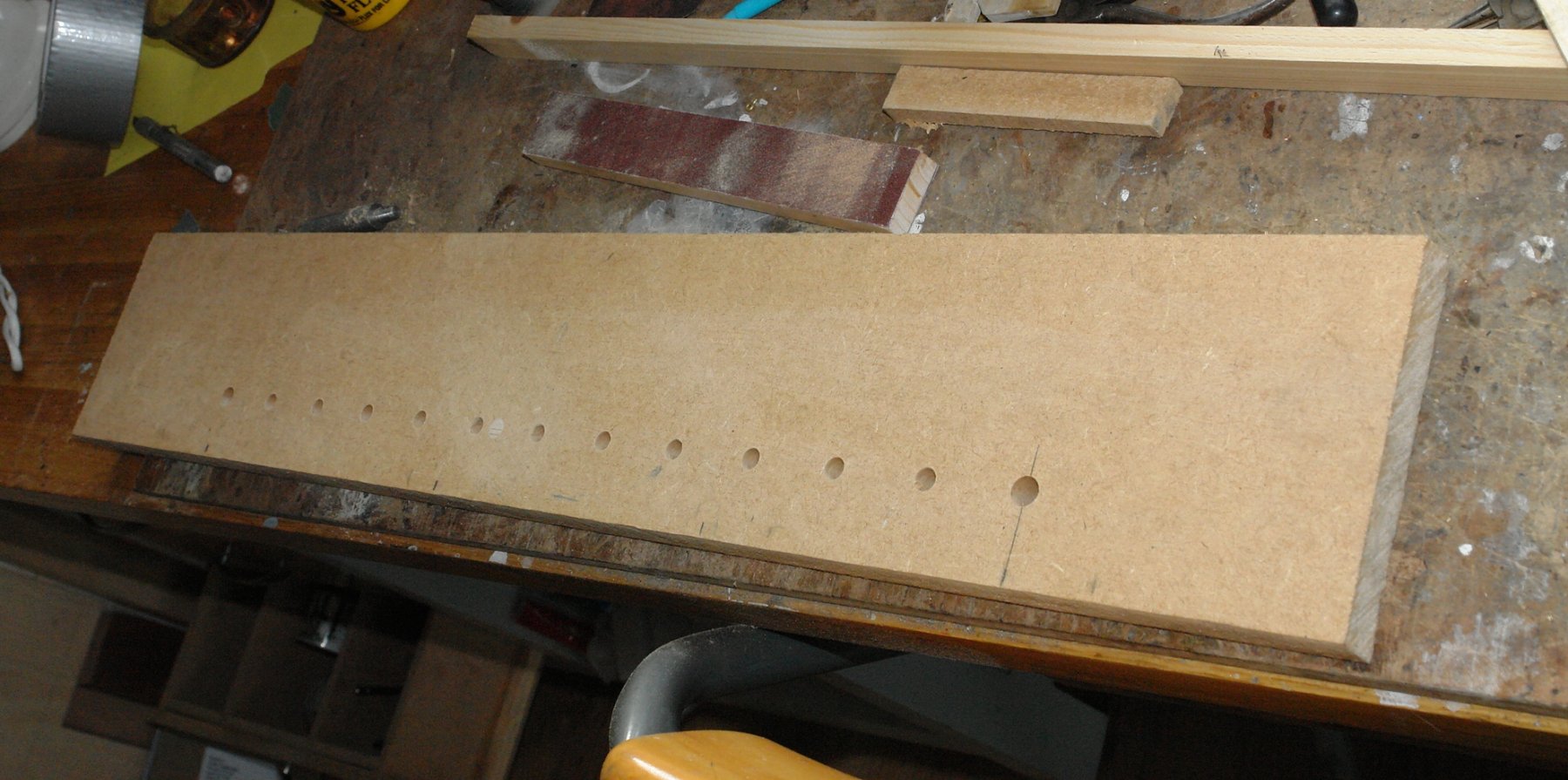
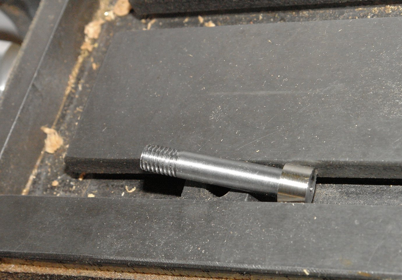
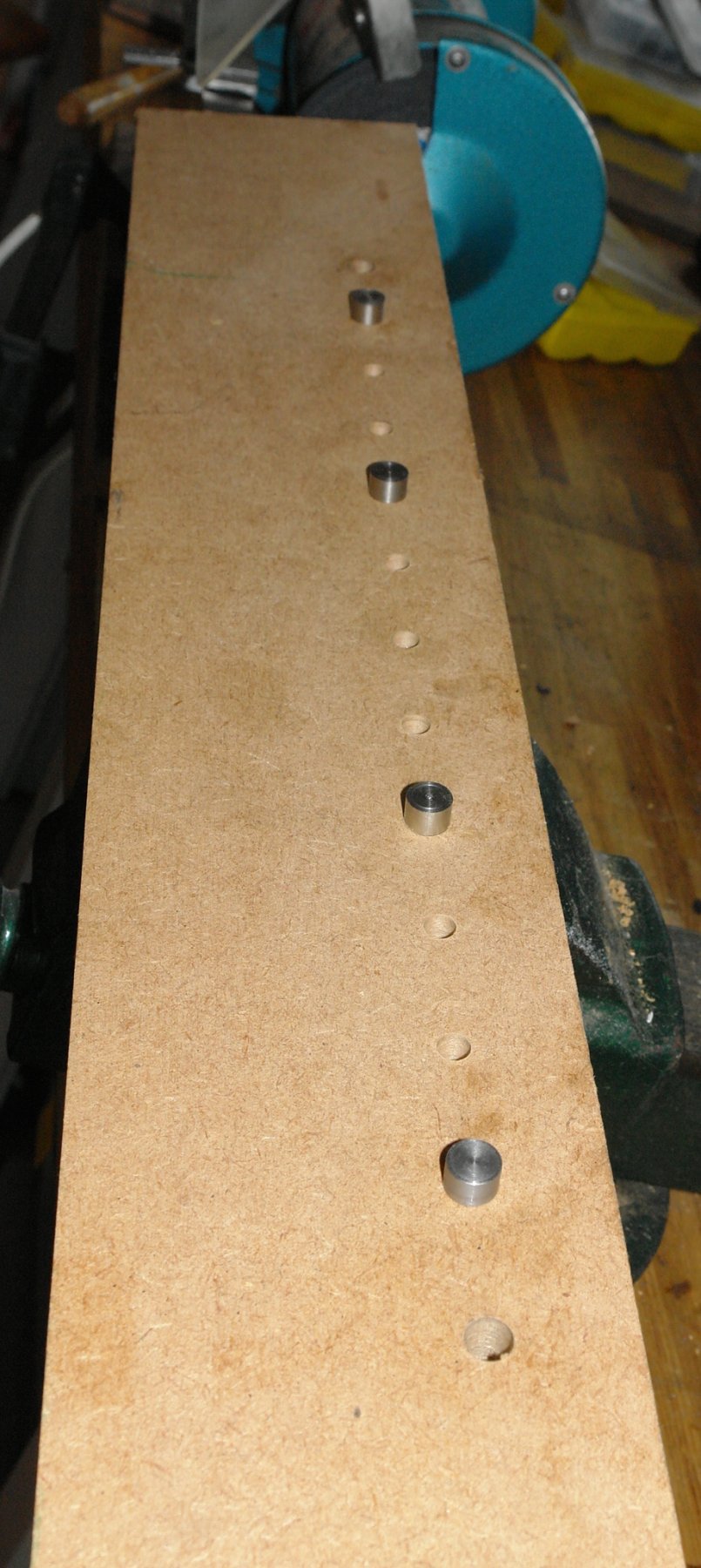
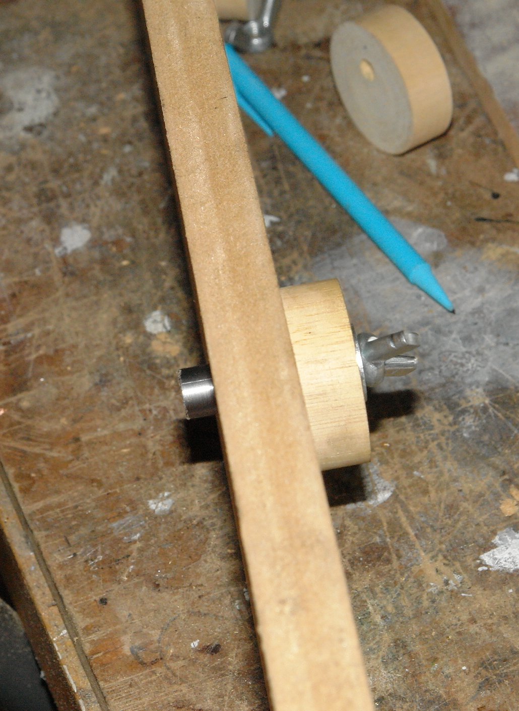
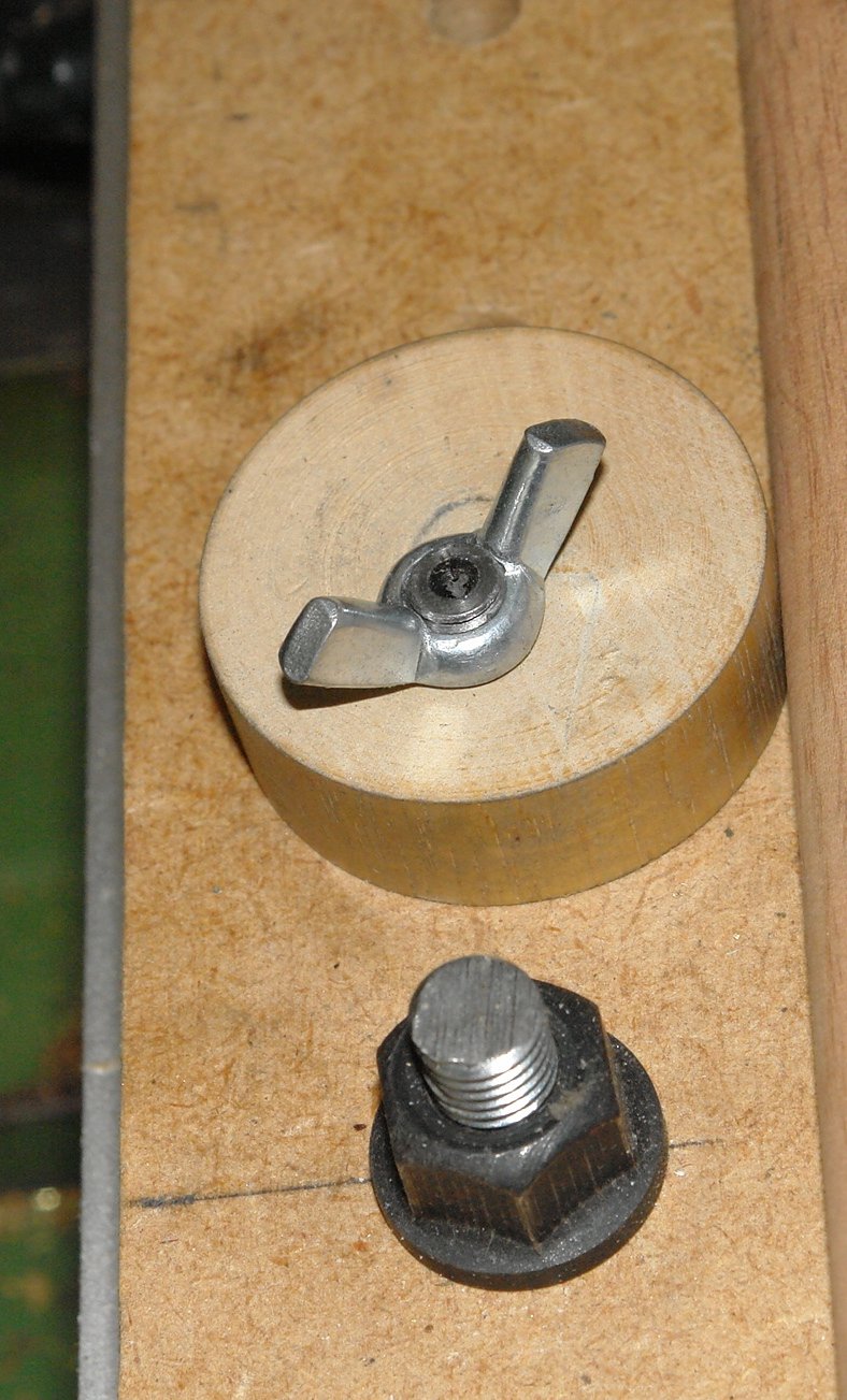
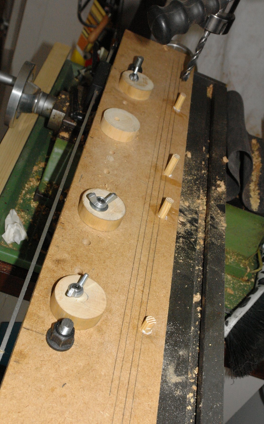
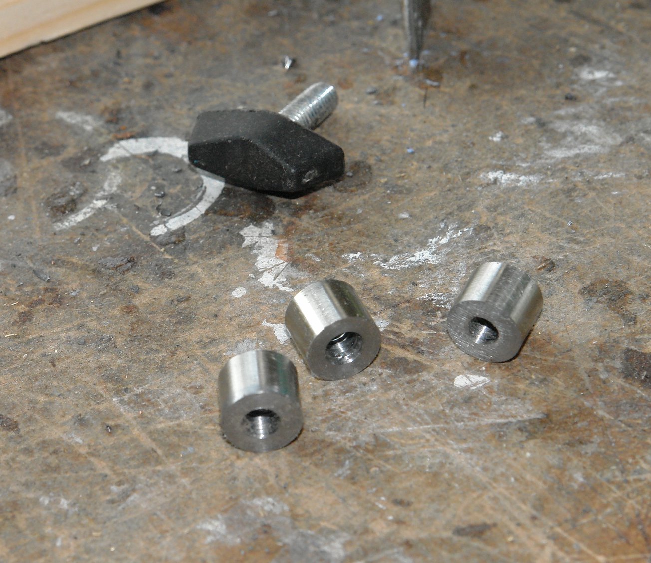
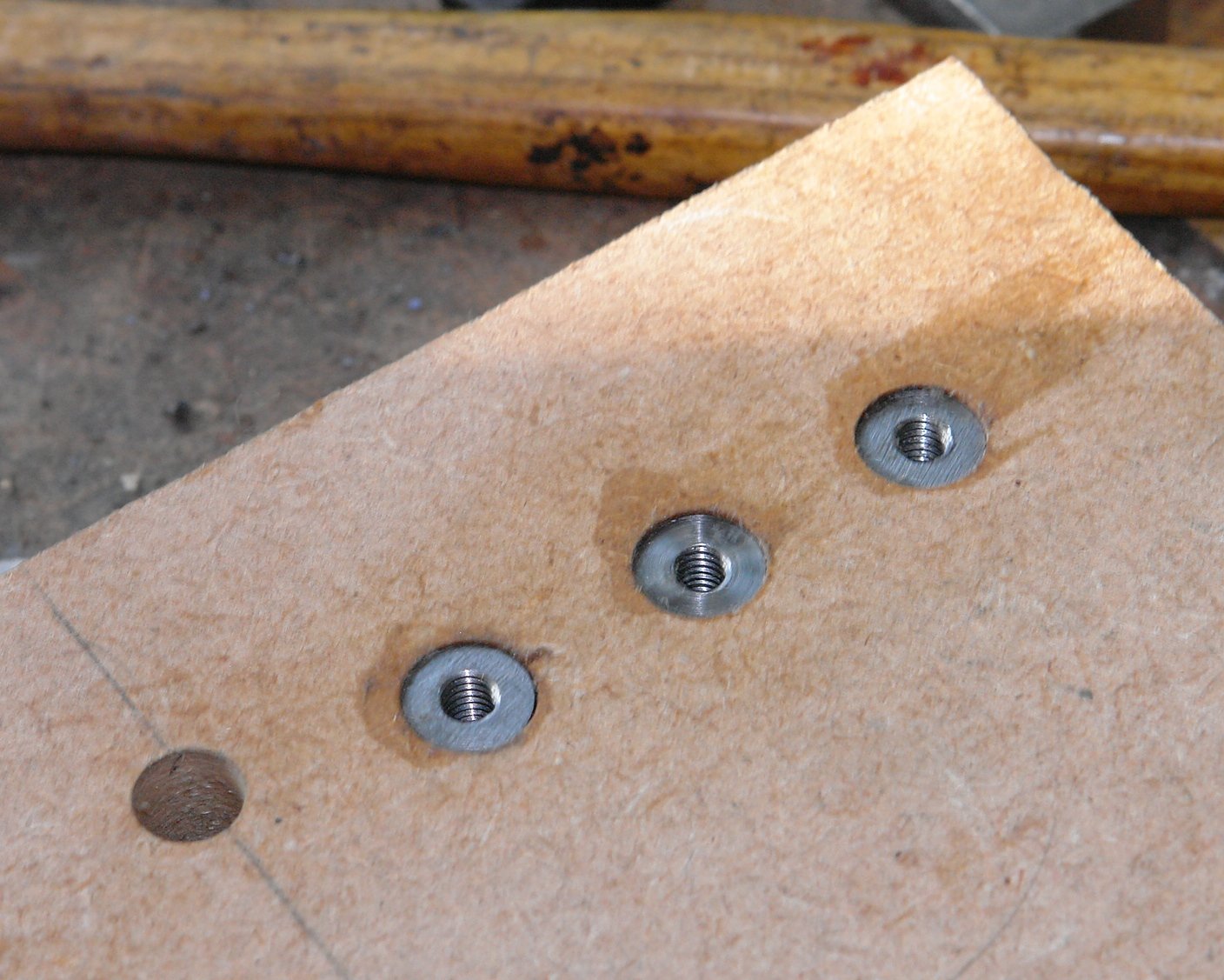
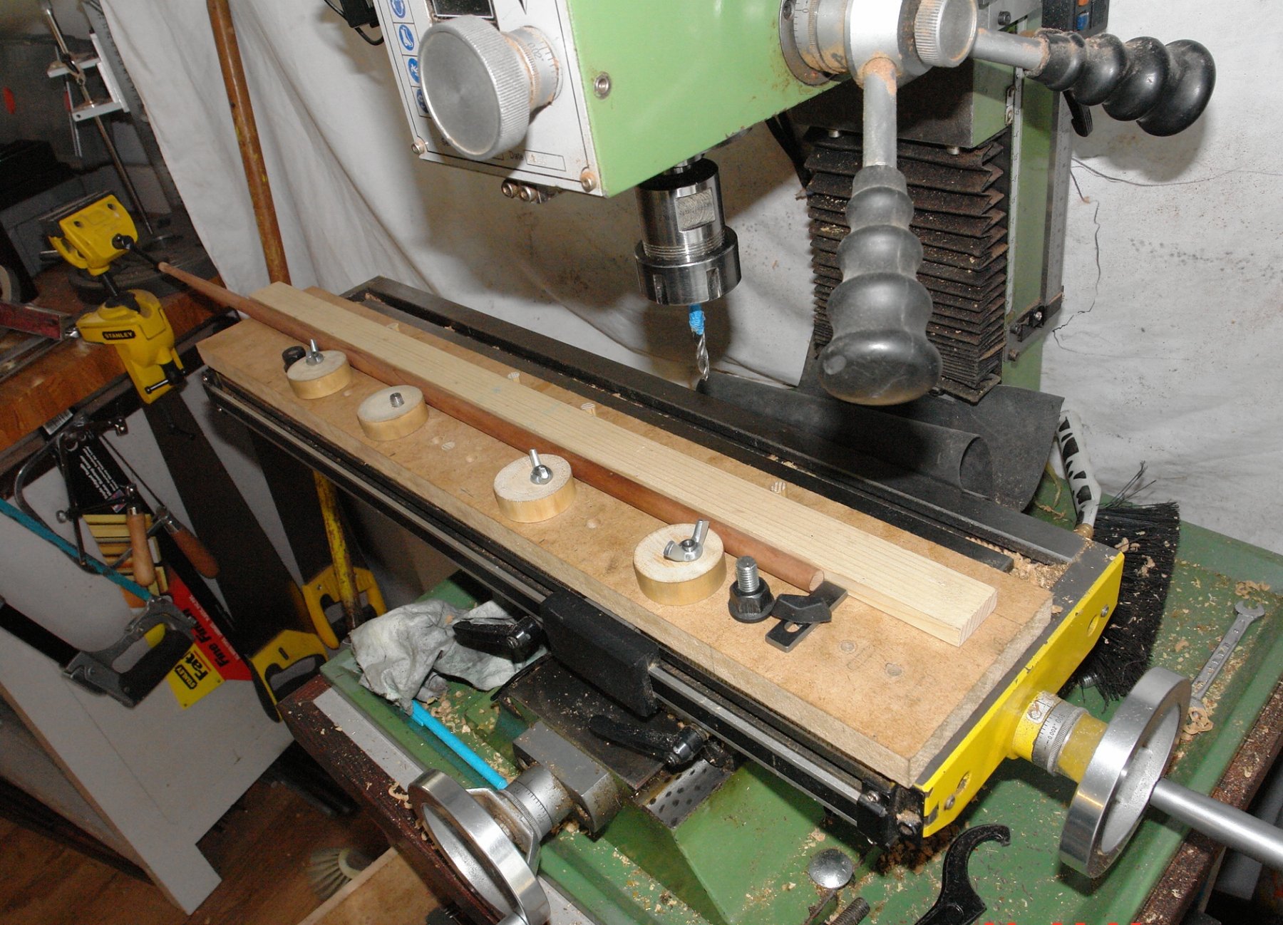
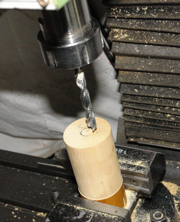
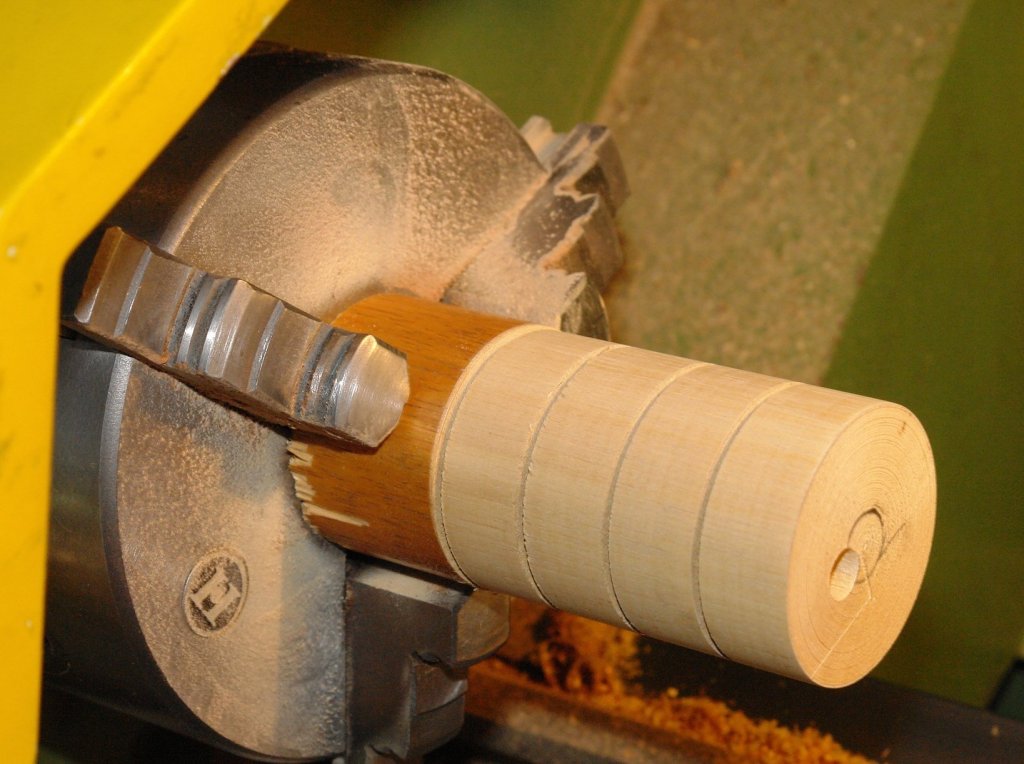
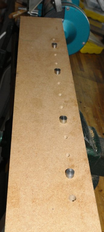
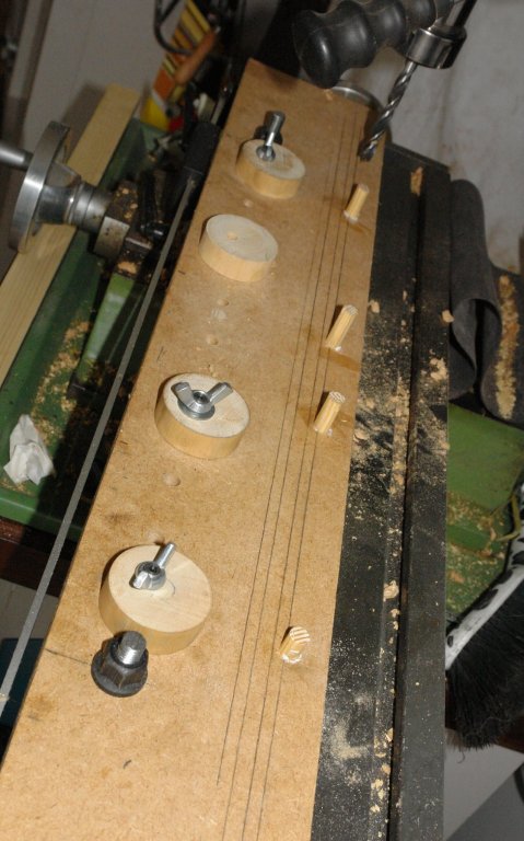
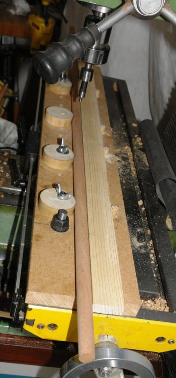
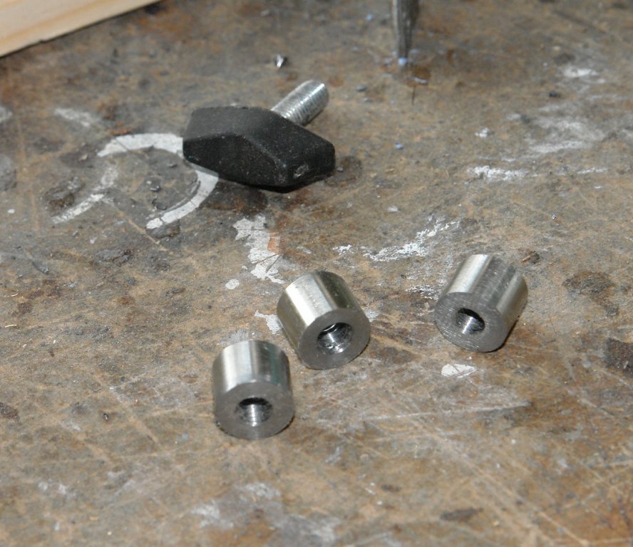
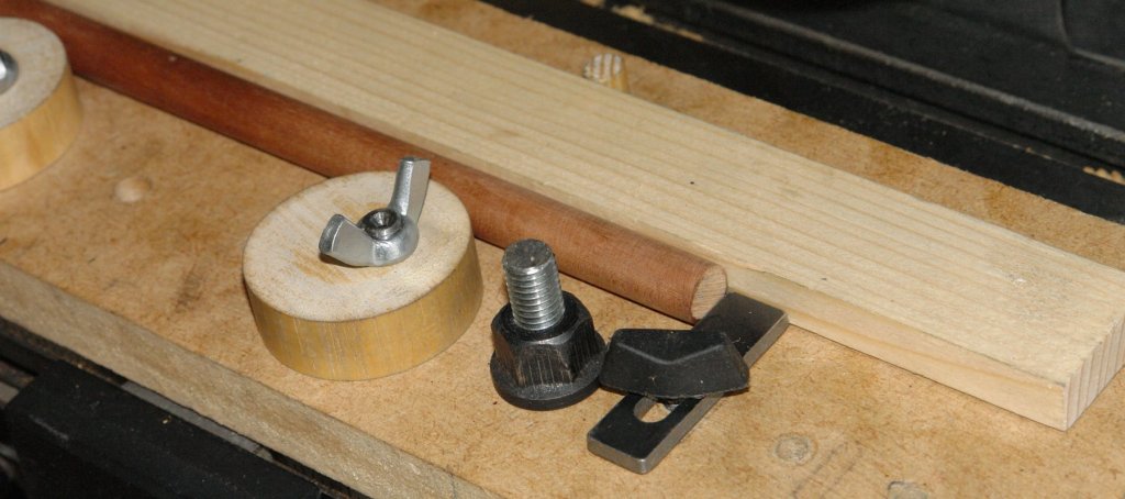
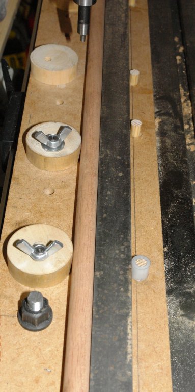
 In the past I have constructed many ad hoc fixtures to enable the accurate machining of masts, spars, yards, booms etc. I decided to have a go at making something more versatile that would work for items of different shapes and sizes. Having made it it seems to work well so I thought it would be worth sharing. I started out with a set of design aspirations. For ease I will refer to "masts" rather than go through the full range of parts each time. 1 Provide solid clamping along the length of the mast. 2 Locate / relocate on the milling table without the need for alignment / set up. 3 Positively locate and relocate the mast so that I can easily remove and replace it on the mill. 4 Clamping devices not to mark / damage the mast. 5 Clamp parallel and taper masts. 6 Clamps to be easy and quick to operate. I started with a clamping concept based upon eccentric circular cams and the build started by cutting a piece of 3/4" MDF to sit on the milling table. I used the mill to accurately drill a series of holes along the length of the MDF to take the cams. The cams themselves were turned (circular) from hardwood. An eccentric hole was drilled along the axis of the cams before they were separated. The cams are mounted on the MDF using a pin. The pin protrudes below the bottom surface of the MDF and the protruding part is cut to a diameter .001" smaller than the slot in the milling table. Once the pins are pushed into the MDF they give positive and repeatable location on the milling bed. The top of the pin locates the cam which is locked by a wing nut. The additional holes allow the cam positions to be varied to suit the mast being worked on. Holes at either end of the MDF take the "T" nut bolts which attach the MDF to the milling table. The MDF was then placed on the milling table (located by the pins) and a row of 4 holes were drilled parallel to the pin holes. Into these holes were placed accurately made dowels. These dowels provide the "fixed" support against which the cams clamp. I think this will become clearer in later photos. A simple piece of wood is then placed up against the dowels. This forms the face against which the mast is clamped. In the following picture a mast is clamped in place. Because the cams act as a finely tapered wedge hand rotation is enough to very rigidly hold the mast. The cams give a lot of flexibility on the diameter of mast that can be held - .200" to .700". But larger is possible by using a narrower wooden strip. At this stage I checked the alignment of the mast to the axis of the mill. The run out was .0015" over a 12" length. Much better than I expected. I did however need an end stop to control the position of the end of the mast. This was relatively easily achieved and for good measure I included an option for 3 positions. See Photos:- The solution to dealing with taper masts is straightforward but does require a bit of trigonometry. The taper is achieved by changing the diameter of one of the fixed dowels. This is done by making a collar to fit over it. This gives a triangle the base of which is the distance between the first and last dowels and the "opposite side" is the thickness of the collar wall = (outside diameter - inside diameter)/2. In the last picture I replaced the wood strip by a steel bar - but this proved to be un-necessary. I still have a few bits to develop but I think thats enough for now - except for the mystery of the missing wing nut!!!!!!


-
Hi guys and ladies I'm still on the furniture stage on the deck of my amati adventure but this will be finished in a couple of weeks. I was wondering of ways to taper the masts , I've considering buying a lathe but i am looking at other ways., as the one i want is about $ 400. Has anyone got a way of tapering masts mine are about 600mm long and 8mm wide .
-
Over the last few months, I have worked through a very challenging task of creating a set of files that cover the rigging of the Royal William. They include text, diagrams and photos arranged in a sequential order of rigging. They are freely available for anybody who wishes to make use of them and it is my fervent desire that they will add to the joy of creating this mighty ship. Having said that, there is still some work to be done on these files to fully complete them. Hopefully, the MSW members will 'jump in' and make this a real community effort through a range of ideas, suggestions and criticisms. I feel that this task is more than one person can handle so I will wait to see what happens. The files concerned range from RW.06 through to RW.10. The link to the Euromodel website is .... https://www.euromodel-ship.com/eng/royal-william-i-i.php Pete
-
 Hi, Am new to this forum but have been making model boat kits for around a year now. To practice planking techniques I started with the kits which had to be smoothed and painted as the full size ships / boats were steel hulled. I'm now moving on to older ships which have timber hulls and have been trying to do some research on the web I'm part way through a build for the HMS Halifax - originally built in Nova Scotia in 1768 and have been studying other builds - both kit and scratch. The kit comes supplied with mahogany, but I see from many images that above the water line, most modellers have chosen different wood for the planking. I understand that most ships of the time would have been painted in one form or another, but I think the models look good using natural wood finish as it shows the planking workmanship off - for better or worse! What I'm unable to find during my research for this and a couple of future builds is what the full size ship was actually planked in. I've found reference to type of timber harvested in the 1800's from Nova Scotia as this would be the logical timber used for ship building in this area but there is a large variety of tree's being harvested and suspect many would be unsuitable for ship building. What I'm also unable to determine is if they would have imported hardwoods even though they had a ready supply of other timbers grown locally. Also complicating things is once the ship was transferred to the British - was it refurbished with native woods, or possibly even imported hardwoods such as from India etc. For a ship that is apparently very well documented I'm really struggling to find the answer - I suppose at the end of the day, most would think it unimportant and to finish as I see pleasing but would like to try and at least be true to the original ship. I'm also ignoring using nails supplied with the kit and intend to use 'tree nails' (apologies if this is not correct term as all these shipping terminology is sometimes confusing to a newbee landlubber!) - so I'll be reducing some dowel wood or other to suitable dimension to represent the original fixings and same issue applies - were these made from the same timber as the planks or were they different (other kits I've used this technique on were basewood planking so the use of toothpicks passed through a tremel achieved a result that was pleasing as the 2 woods were close in colour but different enough that you could see the actual dowel heads) - if the same wood not sure if the fixings would stand out sufficiently to make the extra effort worthwhile but using a different wood completely would look a bit wrong. Any advise or help would be greatly welcome. Next builds in no particular order will be the Thermopylae, Cutty Sark and Norske Love so same issue again, though I plan on copper sheathing the Cutty Sark at least. Regards
 -
I read recently on a boat building forum (real boats) that only three sides of a mast should be tapered. The aft side is left straight. Does this rule apply to our world? Is there an advantage of one method over another (other than ease of construction)? I'm working on Model Shipways brig Niagara, & am trying to taper the masts now. Dale G Elhardt
-
I am looking for a model to learn about rigging techniques. I am building 2 ships now but want to practice rigging before I get to the real thing. Any suggestions would be great. I was thinking of a model with the hull already done I just need to start on the masts and the rigging. Thanks in advance. Brad
-
 Hello, I am finishing up the Royal yacht Mary by Mamoli, and working on the masts and spars. They are from basswood and I hate them. They are warped and break easily when you sand them thin. I did some research in the books I have and a website from Gene Larson, on what type of wood to use for mast and spars. They suggest the following: Sitka spruce, lemon wood, lance wood, maple, cherry and red cedar. I need the following diameters and I have put them both in mm and inches. 8mm or 5/16" 7mm or 17/64" 6mm or 15/64" 5mm or 3/16" 4mm or 5/32" 3mm or 1/8" 2mm or 5/64" I have checked the following places for dowels and diameters and types wood They all have the common diameters but not 5/64 or 15/62. http://www.nationalbalsa.com/ http://dlumberyard.com/index.html http://www.hobbymillusa.com/ http://www.modelexpo-online.com/default.asp (they used to have so much more) http://www.woodcraft.com/ Any suggestion of other places I missed that are reliable in the USA. The NET has lots of places that sell dowels and Amazon is connected to many sites I have never heard of. Any suggestions on the type of wood and where to buy is much appreciated. Marc
 -
 Herewith begins my first extended journey into the esoteric art of developing a set of rigging plans pretty much from scratch. On the MSB forum there is an ongoing project to develop plans and build a prototype of the British brig General Hunter (referred to hereafter as the GH). I have, perhaps naively, agreed to tackle the development of a rigging plan for the model. I enjoy a challenge, and particularly enjoy research and analysis, as well as the whole concept of understanding the masting and rigging of a ship is, to me, highly fascinating, so here I go. What I intend to do, since this is research and development rather than actually building the vessel, is to document my research process and decisions here in the same manner as a build log, but likely with fewer pictures. At least, few that represent the output (or input) of spars on a model. I would like this to be a contributory endeavor - please feel free to interject suggestions, ideas, recommendations, or other critical analysis of the process and results. My goal is a set of plans that is representative of the type of rig that the GH may have carried, realizing that the 100% benchmark is not attainable. I will be drawing heavily on research already conducted by Daves, Winston and several others at MSB, as well as information in a set of unpublished manuscripts by Joshua Humphreys and his son from the Pennsylvania Historical Society (transcription from handwritten ye' Olde English into searchable documents is currently well underway by a team at MSB), and archival information both by the archeological team that is excavating and studying the wreck as well as by others such as Stevens of Parks Canada. At some point, may even be touching on Australia and other regions as well - hint hint!). Upcoming topics include (but are by no means limited to) the following: HISTORICAL BACKGROUND Current Knowledge related to the GH Pictorial Analogs and Similar Vessels Dimensions of Masts Dimensions of Yards Furnishing the yards So, pull up a seat, grab some popcorn (I think Sjors was bringing it) and hang on for what could be a fun journey into the Great Lakes and 1812! Best wishes - Wayne