Search the Community
Showing results for tags 'SkipJack'.
Found 13 results
-
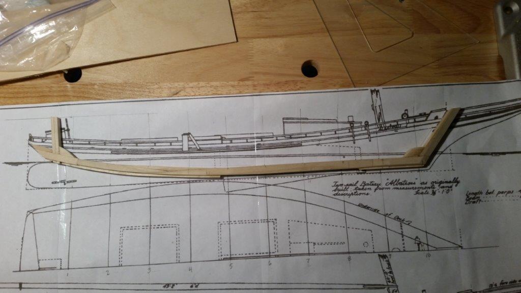
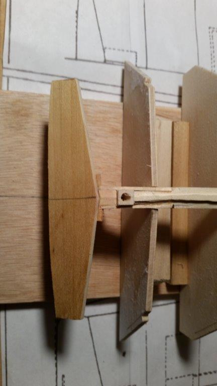
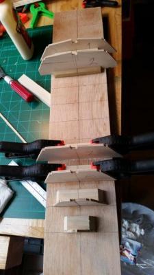
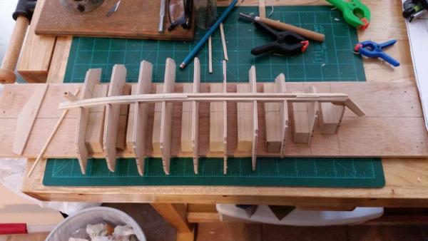
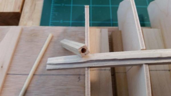
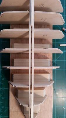
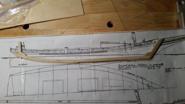
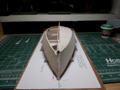
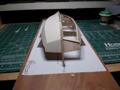
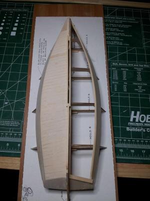
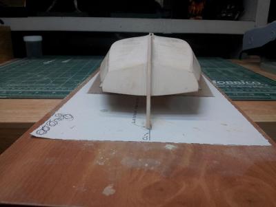
 My current project is the Skipjack Albatross as she was originally built in 1899. Based off of drawings found in "Notes On Chesapeake Bay Skipjacks" by Howard Chapelle. This go around I am working at a smaller scale (3/8" = 1') and using forms to ensure the correct shape and no gaffs. Length bet. perps....44'-2" Beam .....................15'-10" Draft........................2'-9" What made me choose the Albatross was that there are two versions. The As she was built (1899) and then after being modified for gas powered winders and push boat (1911~). I was looking forward to building the gas powered winders and the push boat, but she looks so much cleaner as she was built. I also like the more historical aspect of the as built plan. I have chosen to build the As Built version of the albatross. I ordered the plans for Albatross from the Smithsonian Institute. Two-sail bateau Albatross This fine bateau has been drawn up to show her as built and as raised upon. When originally built at Cambridge in 1899, she was intended both for oystering and crabbing10. Because of her very low sides, however, she had very little room below. Hence, she was raised upon the unusual amount of 12 inches. When first built, the Albatross was considered a very fast sailer, but since being raised upon, her speed has decreased. She requires some ballast to overcome the effects of the increased windage of her sides and great flare. Generally speaking, counter-stern bateaux are are not usually as fast as those with outboard rudders, but there have been some notable exceptions. "Notes on Chesapeake Bay Skipjacks" by Howard I. Chapelle 10. Albatross was built by George E. Leach in Lloyds, Maryland, near Cambridge, according to the carpenter's certificate. CBMM 1998. Gluing the forms down. The forms in place withe thee keelson laid. I used my router table to cut the taper for the crossplanks. I did the starboard side first and it worked fairly well. The Port side did not go as well. I may have to use some putty. The Bow Stem tapered. The Rudder Housing/Sleeve Centerboard Slot The rudder housing glued to the keelson. Transom glued to the keelson. Well that is all for now. I hope to have more soon. Later, Kevin
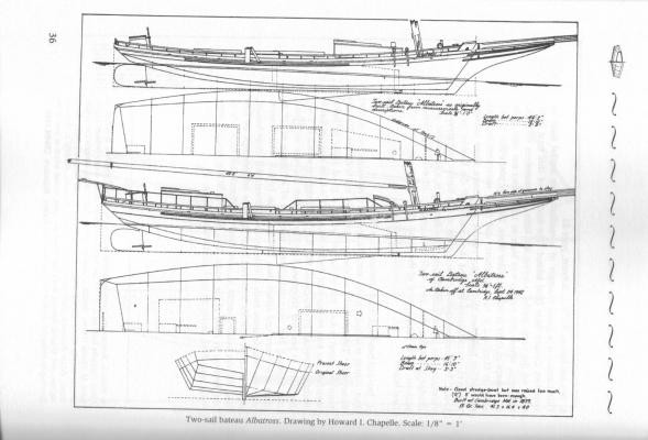

-
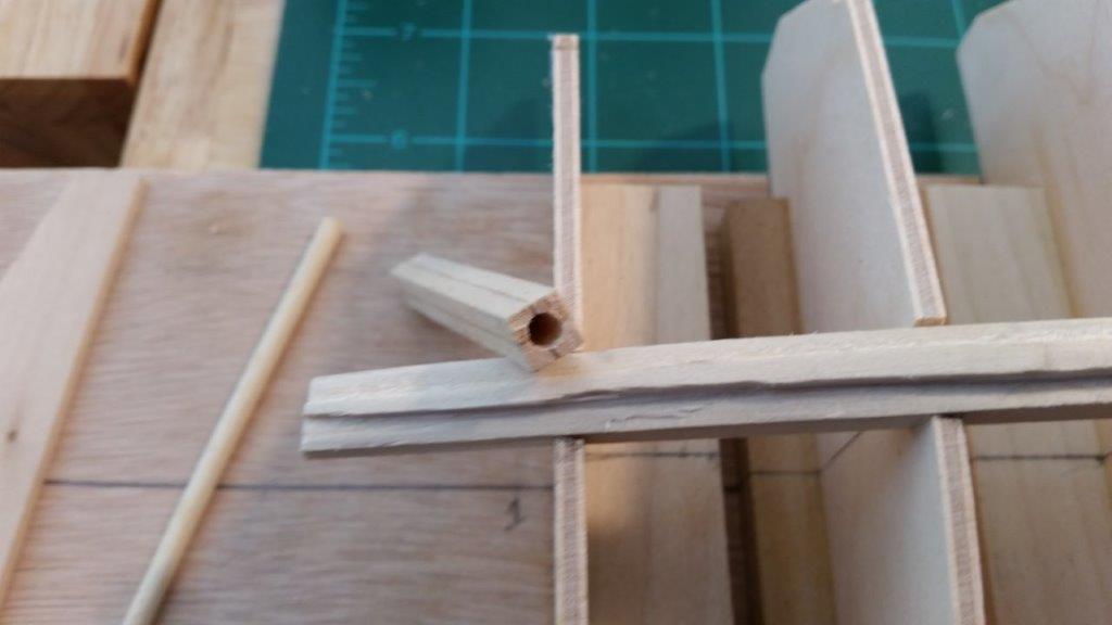
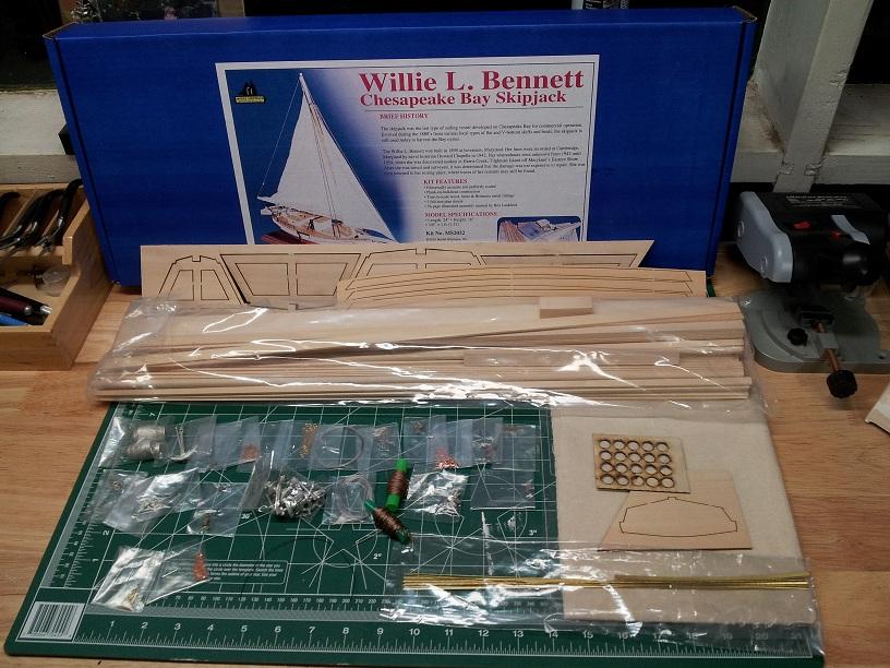
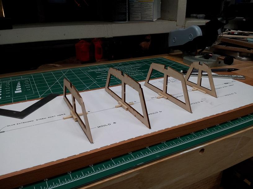
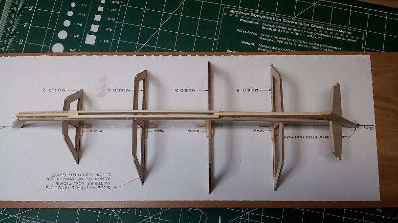
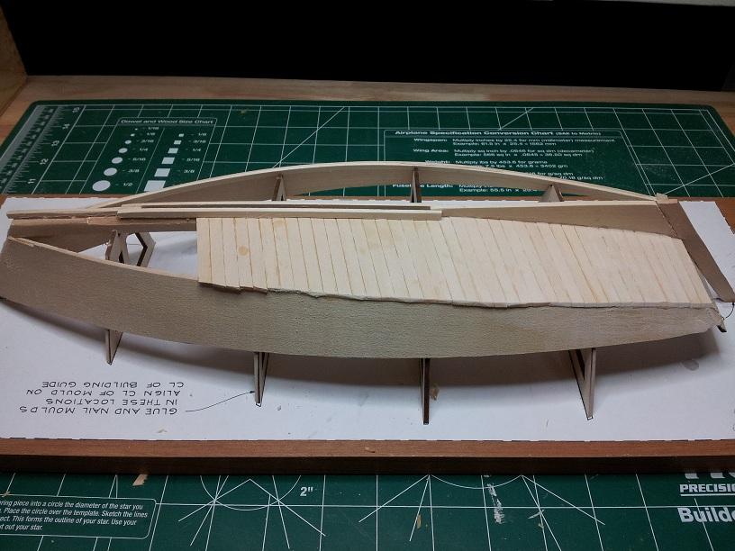
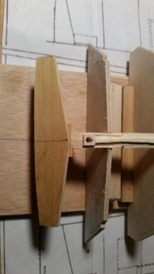
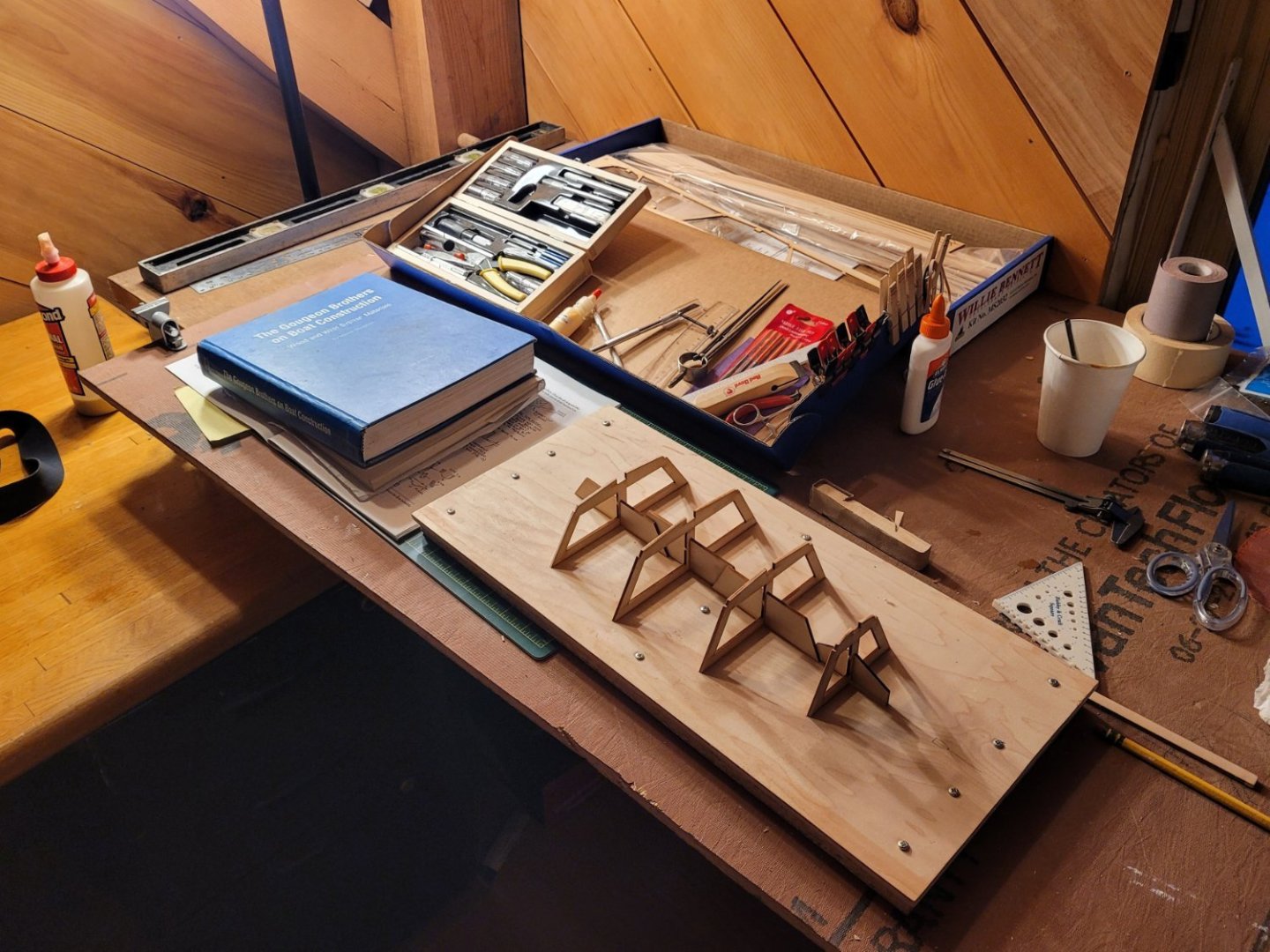
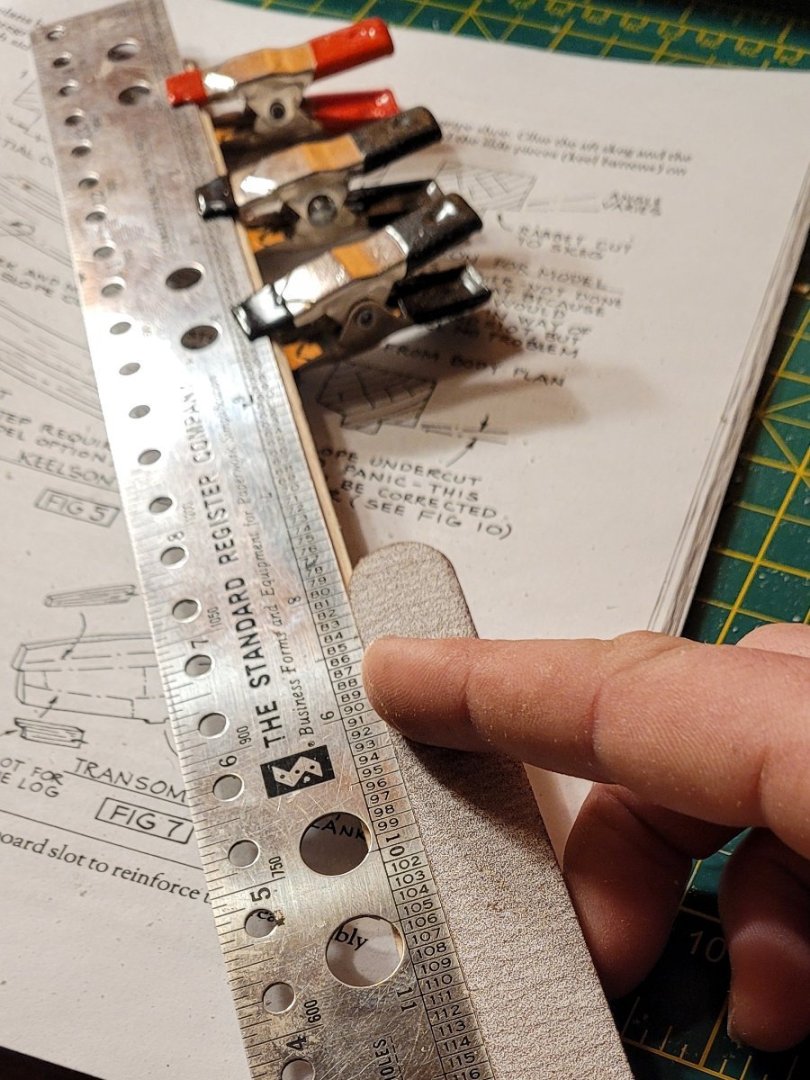
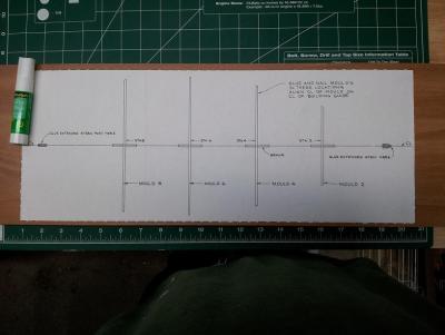
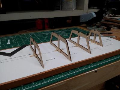
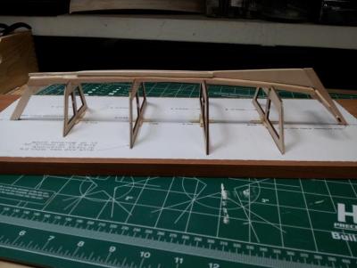
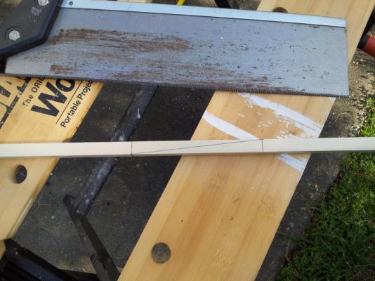
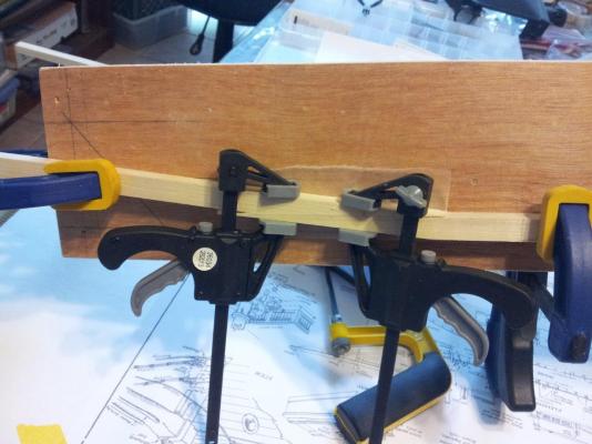
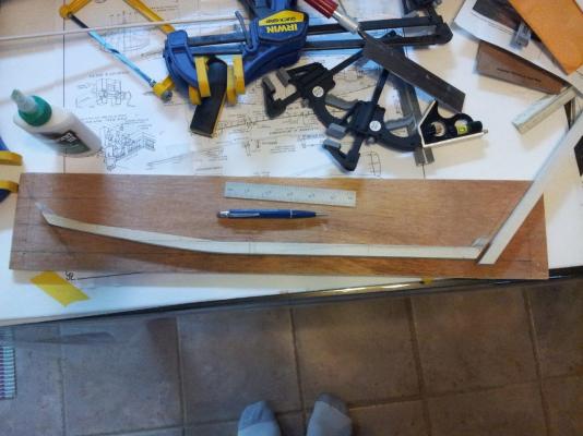
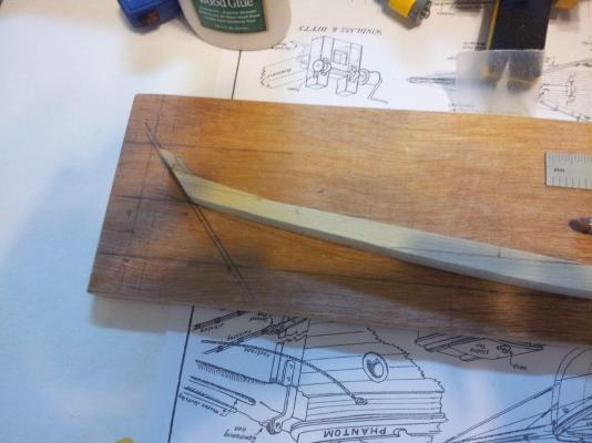
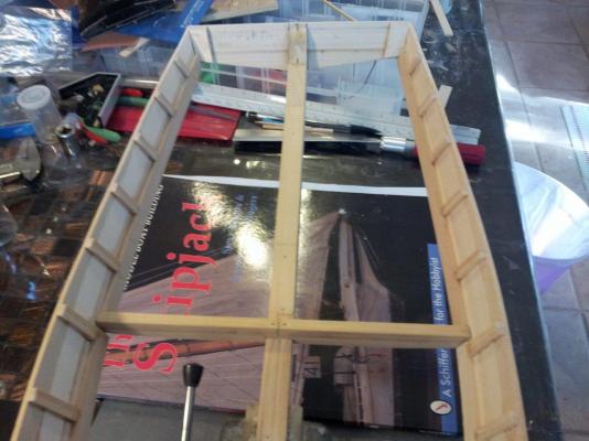
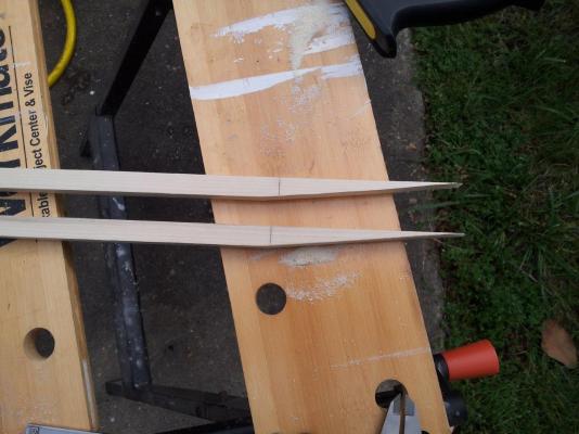
 Having just finished the Lowell Grand Banks Dory, I find myself not yet ready to begin a model of the schooner I'm meaning to build in my garage. And so I reached for the second of the two kits I bought in April 2020 before a bunch of other weird stuff happened, the Willie L Bennett Chesapeake Bay Skipjack. It was quite a contrast opening this kit compared to the little dory model! I'd been advised that this was a good beginner kit when I first looked into this, and I must have even read a build log or two on it before deciding it was a good choice, but if so I had forgotten that I would be greeted with more or less a pile of lumber upon opening the box. It was a little intimidating and I considered putting the whole thing back away since it seems like a lot to get into when I have other projects coming along. Then I got started anyways. I found a 1/4" plywood cutoff just a bit larger than the size shown in the plan, left over from when I built my kitchen cabinets. It was a little bowed, so I fastened a cutoff bit of 5/8" OSB to the bottom and that flattened it right out. I pricked holes through the mold plan into the plywood and connected the dots instead of cutting out that part of the plan and gluing it down, then set the mold up using the cutouts as bracing. I moved on to the keelson tonight. After gluing the three pieces together and sanding it smooth - the laser cutouts weren't quite square, giving it a sawtooth sort of look on end - I sanded an initial bevel into the outer 1/8" strip on each side. I clamped down a straight edge to scribe a cut line, then figured out I could use the straight edge as a guide for an emery board to sand in the rabbet. The keelson sits a bit oddy in the molds, with the forward end sitting quite proud of the notches and the after end recessing in to the point that it will have to be lifted up to fasten the bottom. The next step is going to be some careful measurements and seeing if I need to modify the mold at all.
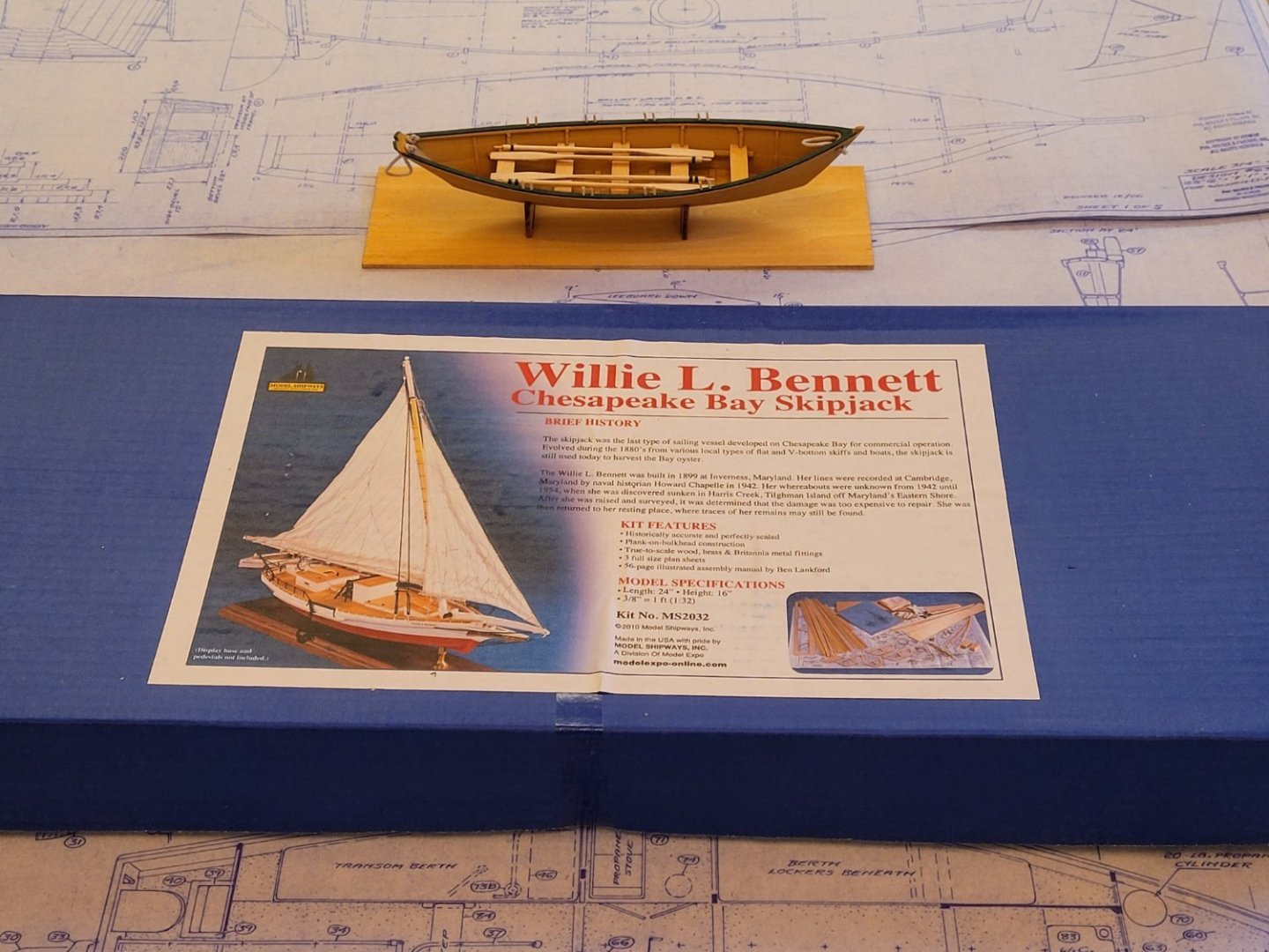
- 2 replies
-
- 4
-

-
- Willie L Bennett
- Model Shipways
- (and 1 more)
-
 I have been interested in models for a long time, even bagan working on some from time to time. Too complicated, too much life interfering with the build process, too much frustration. I actually belonged to the NRG and the Ship Model Society of NJ for a number of years, but little model production. Now retired and relocated to coastal North Carolina and began tinkering with various wood related projects and occasionally looking at the box of wood brought from NJ, including a couple of incomplete models. I had begun a Spritsail skiff a long time ago, using Steve Rogers & Patricia Staby-Rogers plans and reopened the project a year or so ago. Everything is almost complete, waiting for me to create a base and tie, no pun intended, everything together. That leads to this project,, the Skipjack. Some years ago, I visited St Michael's on the Eastern Shore of Maryland, and took a short sail on one of the remaining skipjacks on the Chesapeake Bay. Beautiful work boats! Thus, I began thinking about a model, again using the Roger's plans. Also, I came across Wye River Models, a small model supplier located on the Eastern Shore, near Annapolis. I bought the "box of sticks" which included the Roger's plans. By the way, a Model Ship World member, "Shore thing", created a build log and used the same supplier and plans. A much more advanced builder than me, he built a beautiful model and completed an amazing log. I won't attempt to be as prolific as Shore thing, but will use his advise on my build. A couple of observations before I begin the log process. BTW, if anypone has more accurate information than me on the history, etc., of Skipjacks.. please feel free to comments. Skipjacks were used primarily ro dredge oysters on the Chesapeake, using sail as the method moving from place to place. One mast, shallow draft, wide beam to handle the loads. As the oysters became fewer, so the boats, until only a few still exist. With the advent of the gasoline engine, retaining the requirement the actual dredging must be done only under sail, small pusher boats with engines were introduced. These small yawls only pushsd the boats to a point where sails were raised for the oyster collection process. No two boats were the same, mostly about 40 feet in length. thus, my model will not be a replica of an existing boat, but merely a representation of what one may have looked like. To that point, the Wye River plans are to scale to themsevels, but not to the Rogers plans. I will provide comments on the build progresses. Pictures will be added shortly. The process begins! Thanks for your attention and hopefully your help as I begin thsi endeavor. Dennis
 -
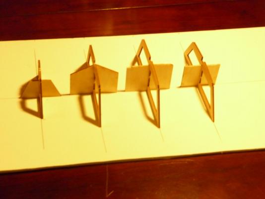
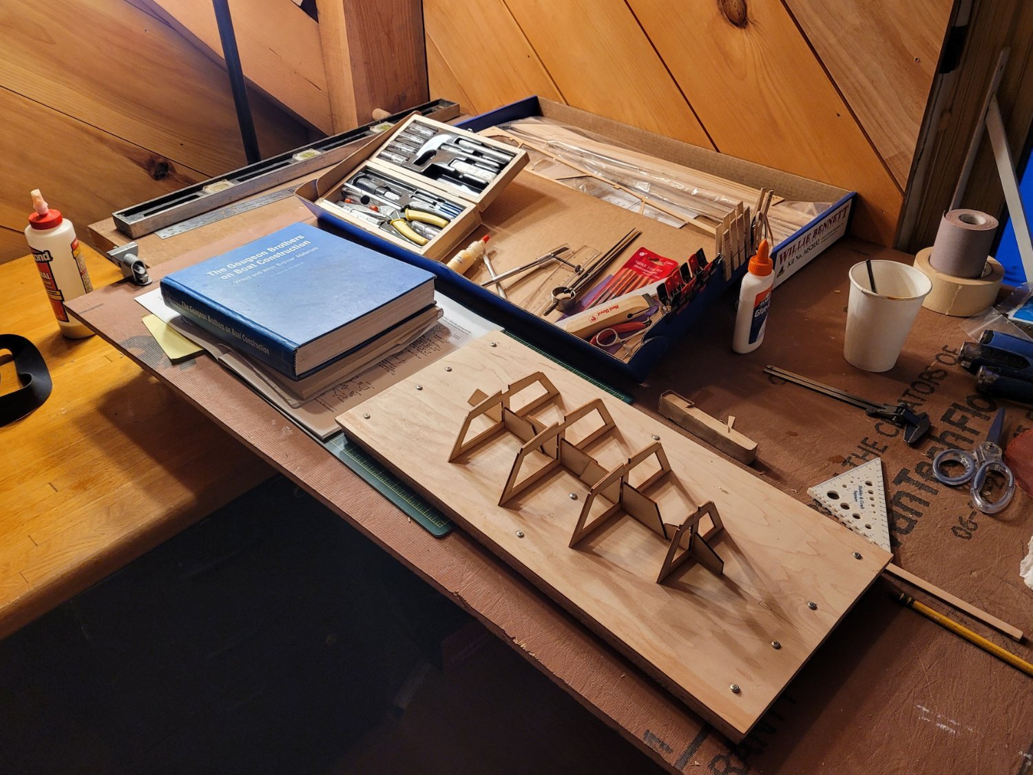
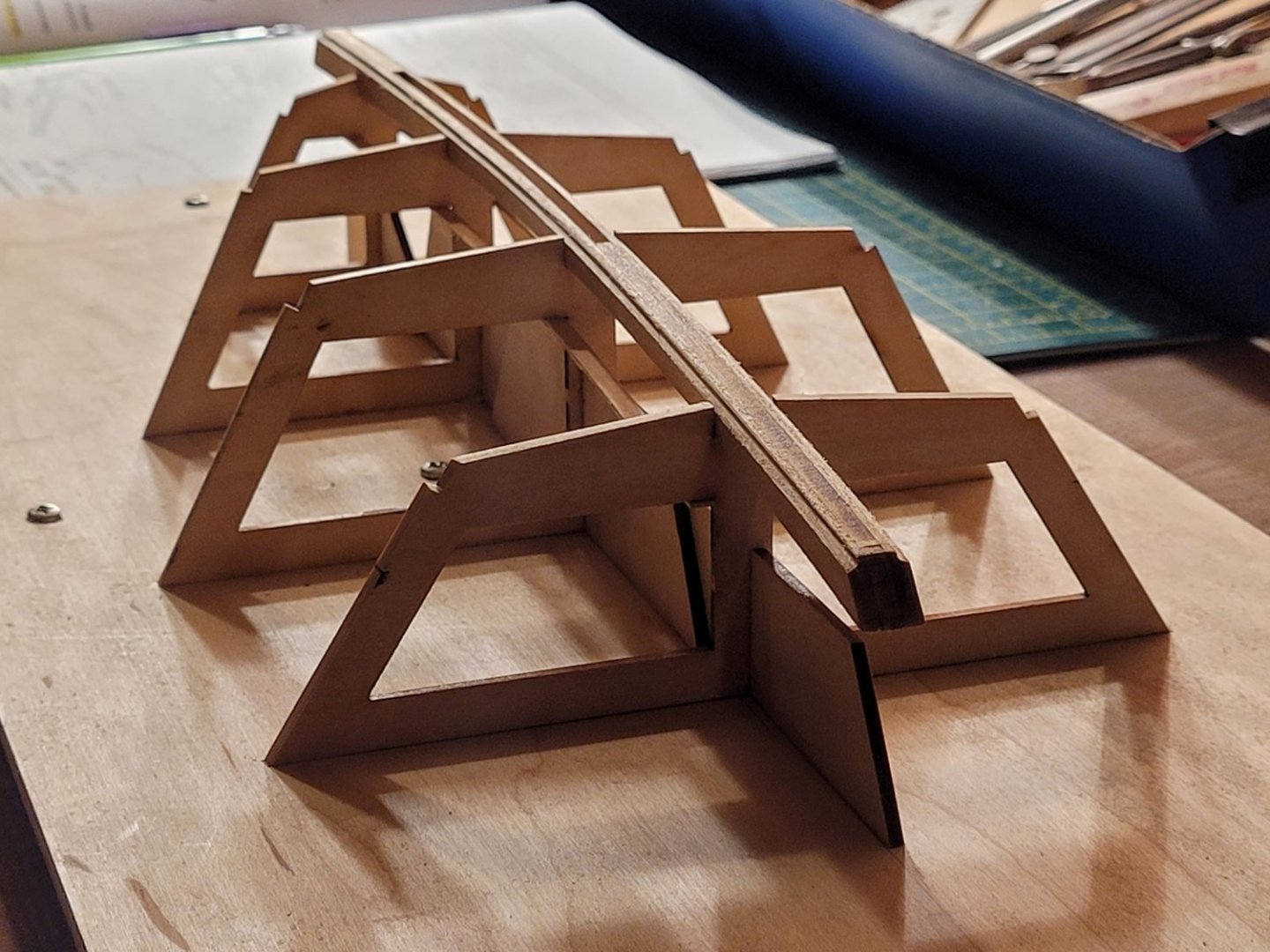
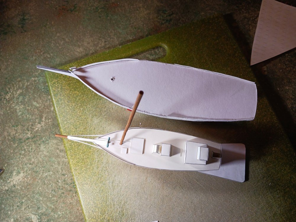
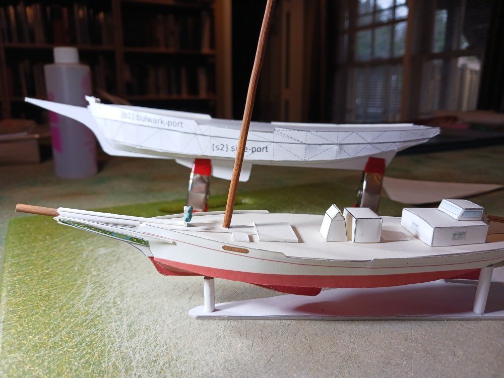
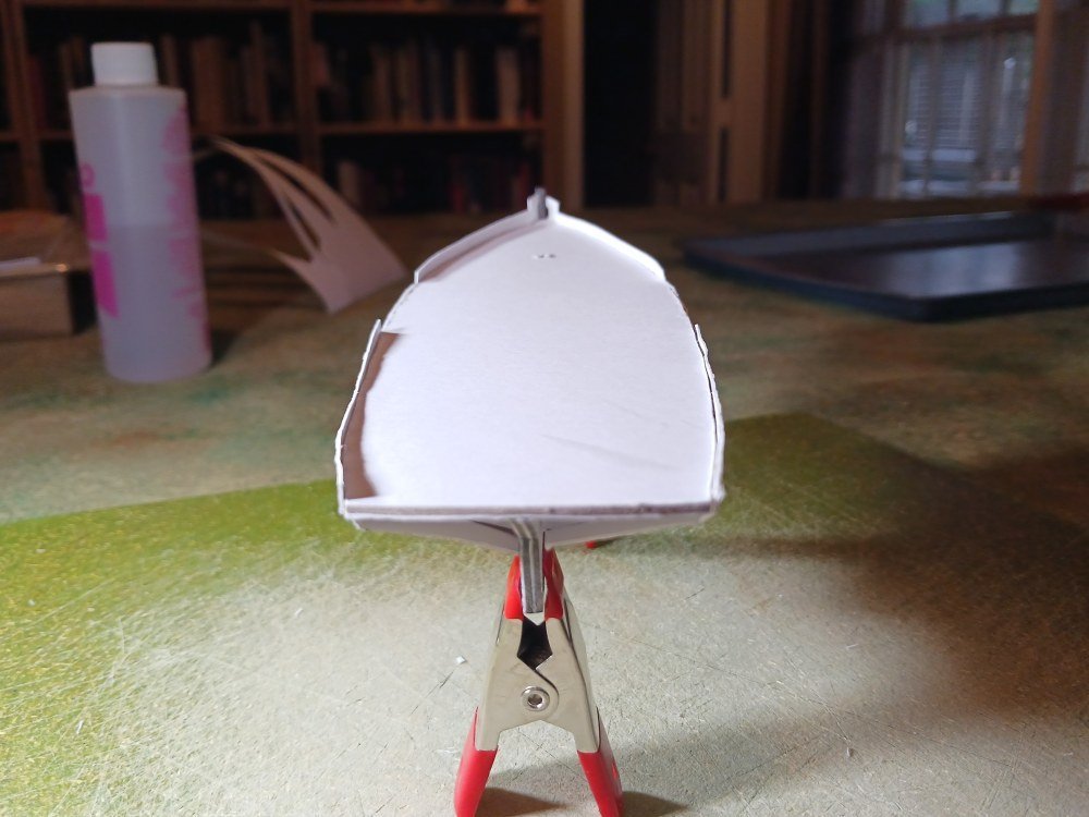
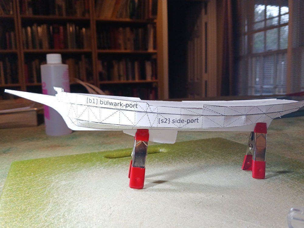
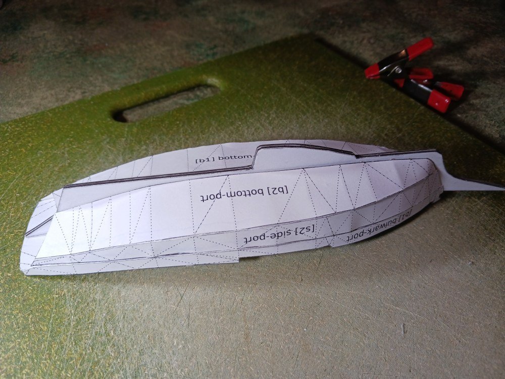
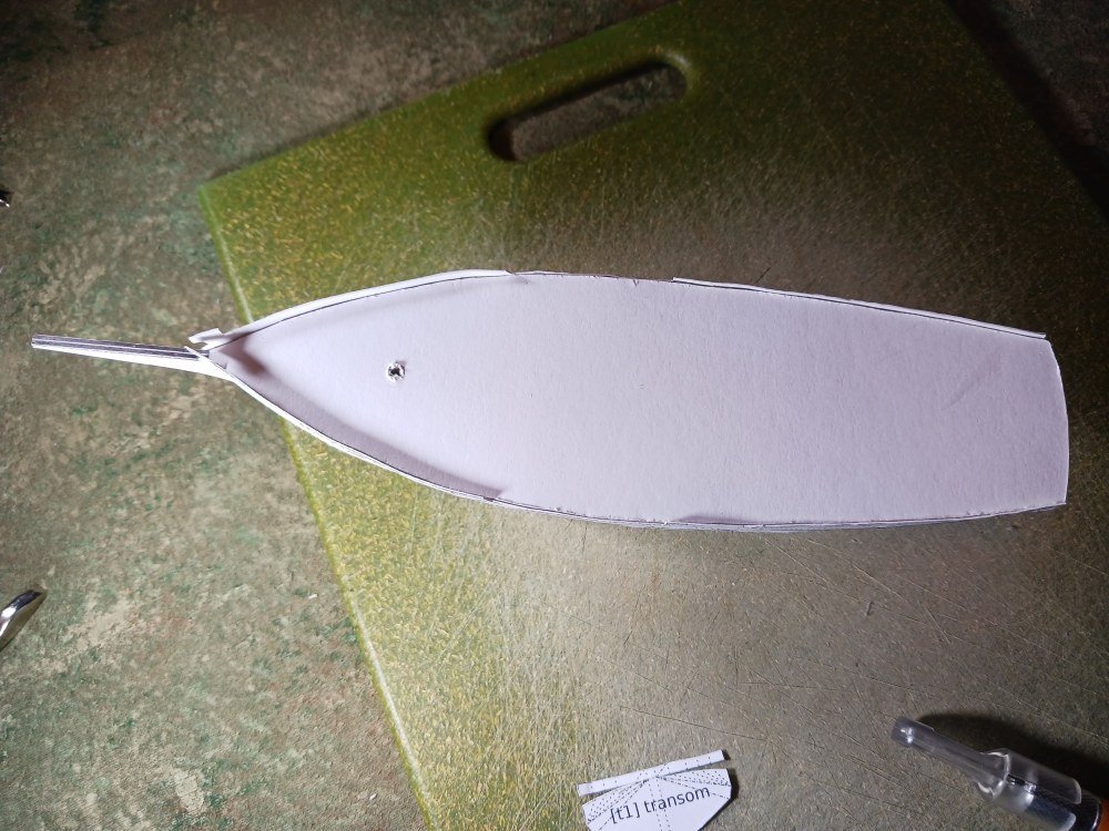
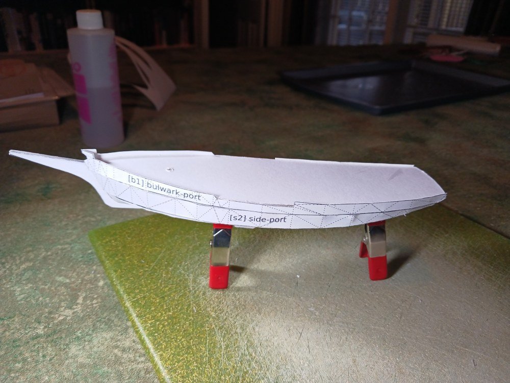
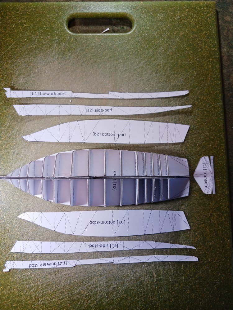
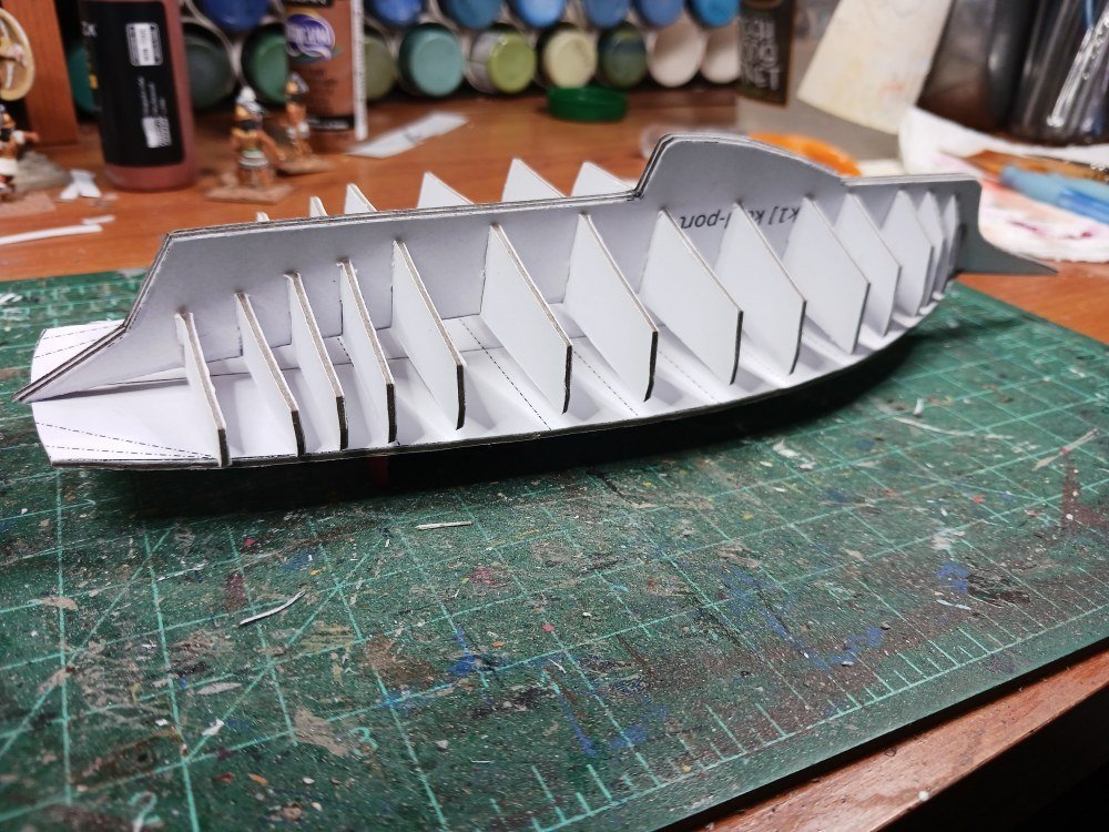
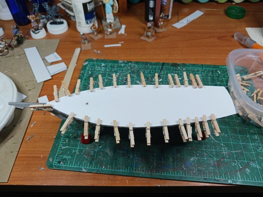
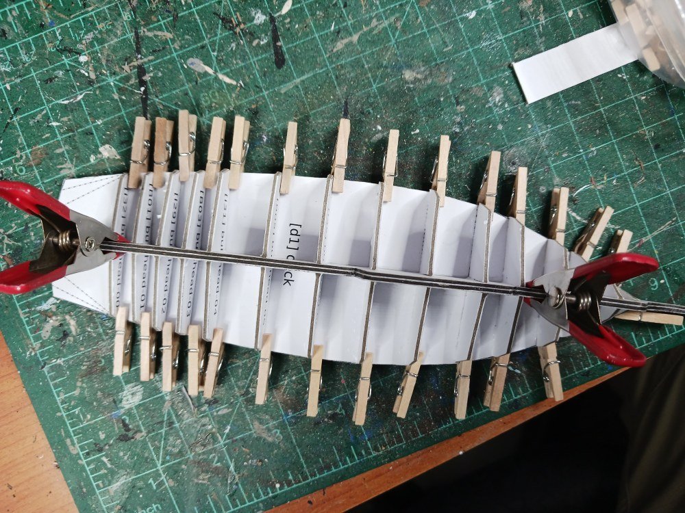
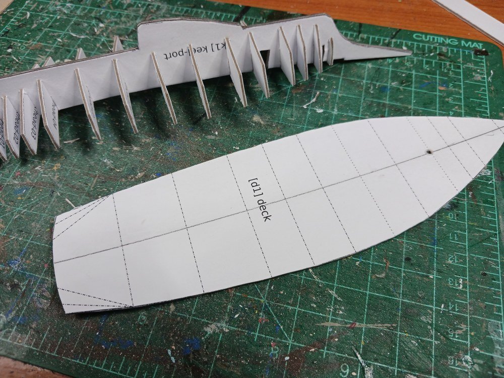
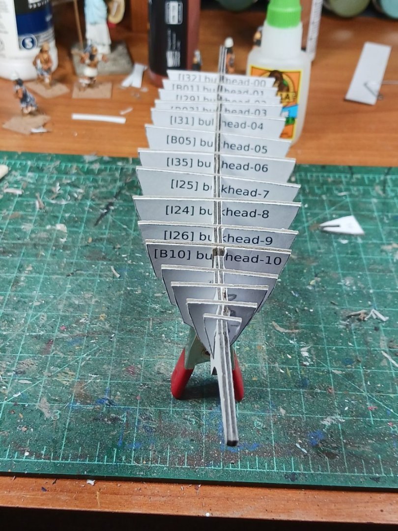
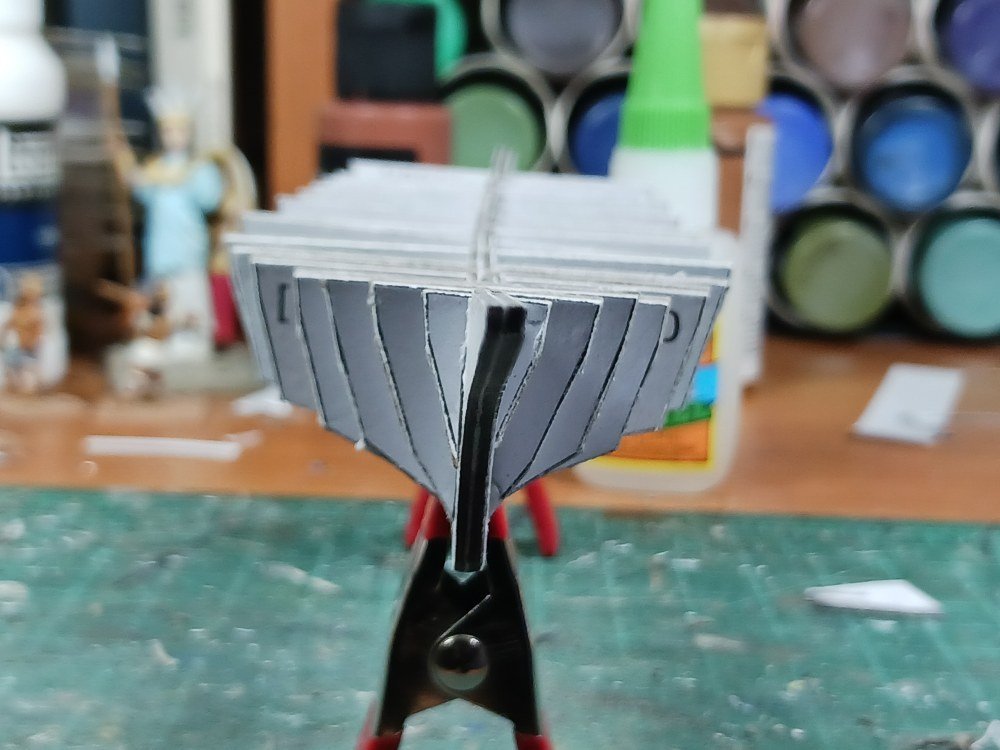
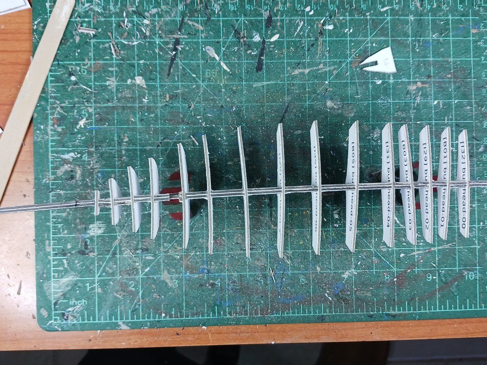
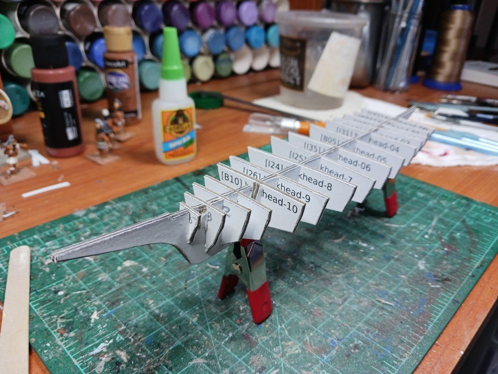
 First, I’d like to wish you all a happy New Year. May Dame Fortune grant you peace, contentedness and many, many hours of happy modeling time! Now, a little back story: Kathryn and I have quite a lengthy relationship. Well, frankly I’ve been infatuated with her for years but she doesn’t know I exist. (But the story of my adolescence doesn't need to be retold here!) I started designing a card model of the skipjack Kathryn in 2016 based on the HAER papers available from the US Library of Congress (https://loc.gov/pictures/item/md1454/). I refer you to an old build log I did at PaperModelers.com: https://www.papermodelers.com/forum/design-threads/37710-1-100-scale-chesapeake-skipjack.html. Life happened, other hobbies took priority, and I drifted away from model building. Meanwhile, the unfinished Kathryn sat ignored on the mantel in my ‘man cave’. But I didn’t completely forget about my old flame. One of the competing hobbies is the open source flight simulator ‘Flight Gear’. Being a contrarian, I wanted to use it to simulate sail boats. So I enhanced the basic virtual model of Kathryn, ported her into Flight Gear and started (with the help of the Flight Gear forum members) to tinker with the configuration files in order to ‘sail’ the virtual seas. I called it ‘Float Gear’. I refer you to the Flight Gear forum if you’re interested in that unfinished journey: https://forum.flightgear.org/viewtopic.php?f=4&t=40606 Now that the worm has turned yet again and my interest in ship models has resurfaced I’d like to revisit the old girl yet again. One thing I want to accomplish is a larger scale. The original card model was at 1/100 scale—common enough for card models but a bit small for my eyesight these days. I wanted to go to 1/72 scale to match the Viking ship I recently finished. I also wanted to try out a different electronic workflow. I still enjoy using Wings3d (www.wings3d.com) to create virtual models and the original model is still valid. However, back in ’16 I wrote my own script to extract UV coordinates from the model and output them in SVG format in order to create the patterns for card modeling. UV mapping was (and remains) a tedious process in Wings3d. And, UV coordinates don’t necessarily reflect the true shape of the model’s surfaces. Let’s just say it was more work than it was worth. Making revisions was a nightmare. However, over the intervening 7 years other tools have become available. I recently came across a plug-in for Blender which ‘unrolls’ a 3d model. I want to explore that option and see if it really is usable for card modeling or if it is still too limited. So far, the signs are good. In future posts I intend to document how I’ve used Wings3d, Blender and Inkscape to design a card model of Kathryn. While I’m not entirely certain this experiment is going to work, I’m fairly convinced that—at least for a fairly simple model—the real challenge is going to be my rather limited modeling experience. But for now I’ve accomplished enough with a test build to show some progress. The pictures pick up after I’ve cut the longitudinal spine and various bulkheads out of 1mm chipboard. The keel/spine is then doubled to give a final thickness of 2mm. I have explored having these pieces laser cut by a third party but I finally decided I was putting the cart before the horse. I think I need to ensure the design is good before committing to that. After all, I want to make sure it's functional before going for efficiency and ease of construction. As mentioned elsewhere there was a fair amount of warping going on with the spine and the bulkheads. Nevertheless, I dry-fitted all the components in order to assess the situation. Puzzling this out it dawned on me that I had the locations of a number of the bulkheads and the spine marked on the deck piece. That was not intentional, it was just a by-product of the modeling/unrolling process. But I figured I could use those marks to ensure the straightness of the framework. Then I proceeded to cut out the various side pieces. Again, the dotted lines represent the triangles of the electronic model. But as I assembled the model I found that they provided reliable guides to aligning everything. Notice the bottle of isopropyl alcohol in the background. I had inadvertently skipped gluing the 'skin' to one of the bulwarks. This resulted in a bit of puckering since the side pieces do undergo a bit of twisting to make them fit. So... I had my first experience of using IPA to unglue things. Actually, it works pretty well. Poured a little IPA in my paint tray and used a cotton swab to apply it to the glue joints. After giving it a few moments to soak in I carefully started to separate the joins with a dental tool I keep in the hobby toolbox. I had to unglue four bulkheads to get to the puckered area. No harm done, though. The IPA did cause some of the printed ink to run slightly but it did not affect the paper at all. You can also notice that Kathryn suffers from 'hungry horse' syndrome. The smaller, 1/100 scale version didn't suffer like this. IIRC, the card I'm using for the skin is 67#. Maybe 90 or 110# would be better for this larger model. While the model in general is incredibly sturdy, the skin seems more flimsy than in the smaller model. I suppose this is due to the card having to span larger distances at 1/72 scale than it does at 1/100. You can really notice it along the sides of the hull from an end view. Here's a view of both the old 1/100 and the new 1/72 scale models for comparison. And finally a shot to compare sizes between the two models. I've not yet attached the transom and it appears that I've cut the deck about 1mm too long. But I think the next step is to lay on a second layer of skin to smooth out the starving nag look. I'm not sure if I need to apply some putty and a sanding stick to smooth out the inner skin or whether that would just be extra work with no significant benefit. My intent is to make the outer layer slightly longer than the first and to arrange them so that the seams between the top and middle pieces are staggered (probably at the waterline rather than higher up as they are in the first skin). The seam between the middle and bottom will of course still be located at the chine. A second skinning will also allow me to finish up the graphics. After that I'll deal with the transom. Well, that's how things sit for now.
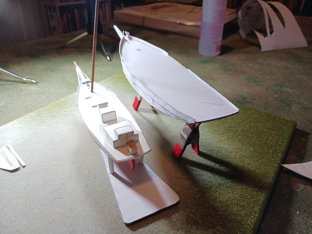
-
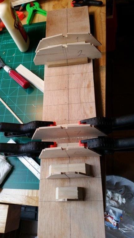
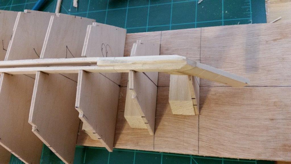
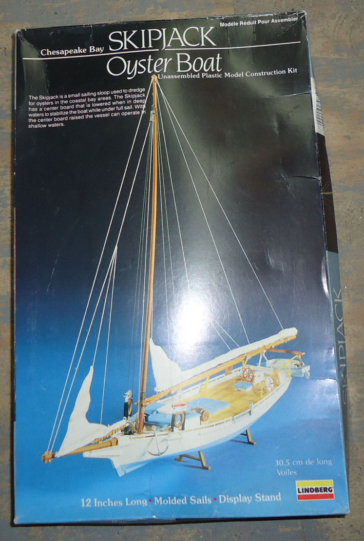
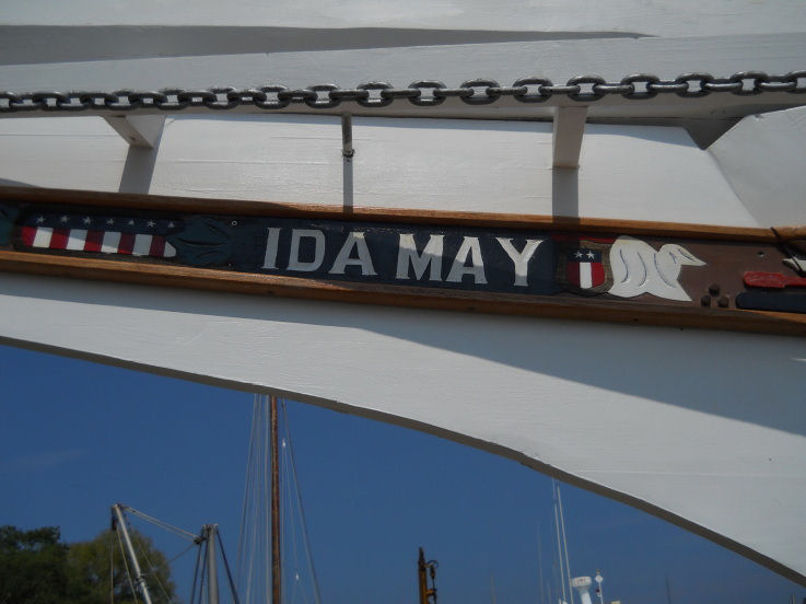
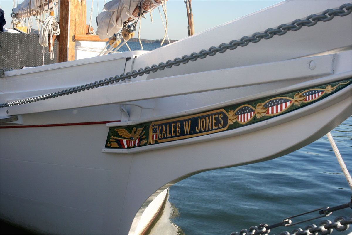
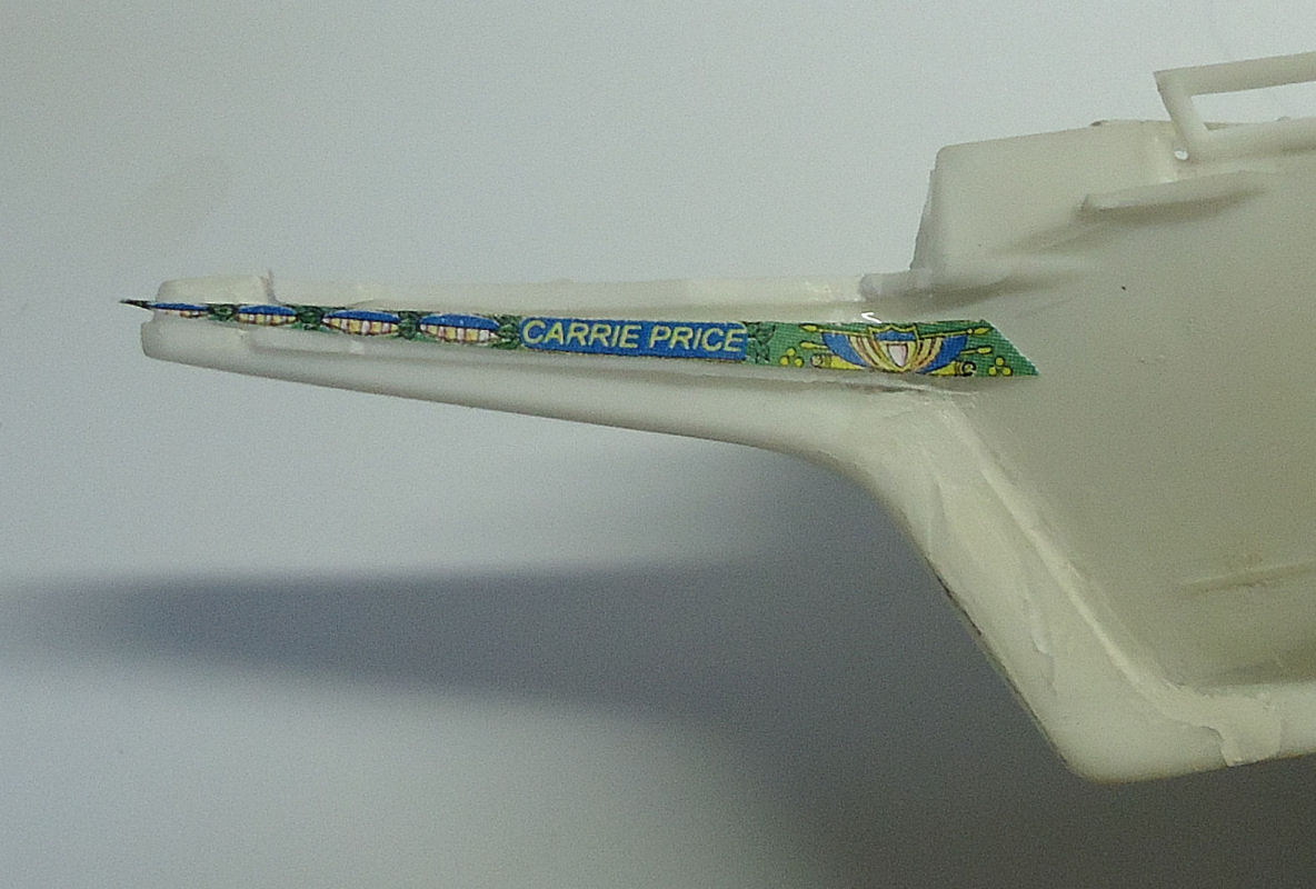
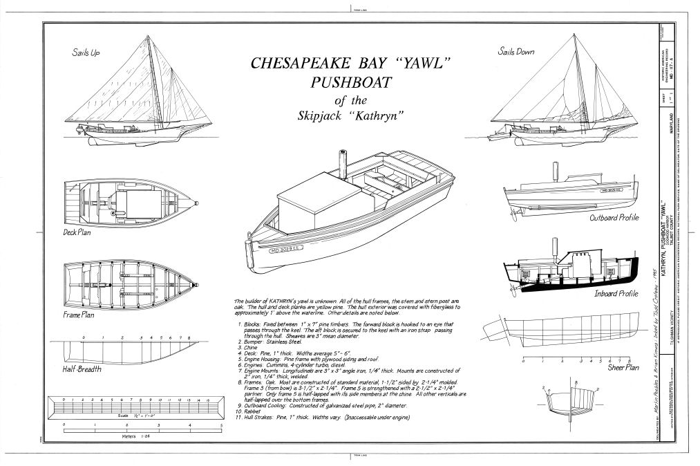
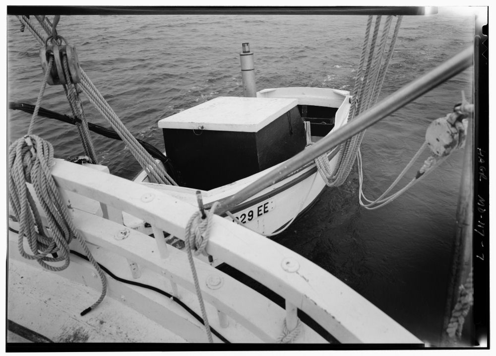
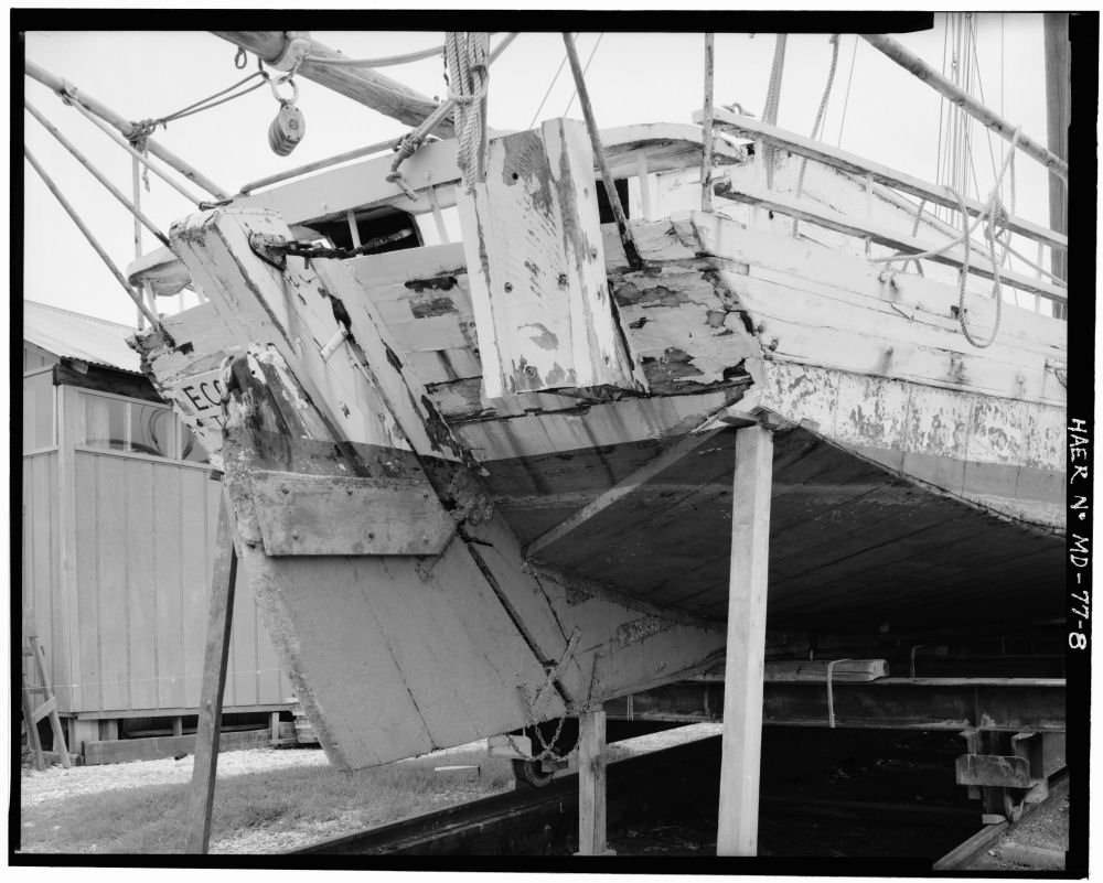
 Part 01 This is a build of the Skipjack Carrie Price using the Pyro Chesapeake Skipjack Oyster Boat model kit. After some research I found out that the Lindberg/Pyro kit is a model of the Carrie Price as recorded by Howard Chapelle. After I started the kit I found the name cast on the transom, but had not noticed it before I started my research. The Carrie Price is one of the projects in “American Ship Models and How to Build Them” by V. R. Grimwood and Howard I. Chapelle. I am using the plans in this book to build and update this kit. I am planning to depict her as build around 1895. I’m not going to make this a museum quality model, but will do my best to make it a good one. According to the Chapelle drawings the model comes as close as I could measure to 1/64th scale, the same as the book drawings. This will be somewhat of a slow build, as I am also working to expand my shed/shop, and the finished section is a mess, with “stuff” from the unfinished portion (enclosed, but no insulation, electric, etc.) piled into the finished area and my work area. Also I decided to do this build log after I had partially assembled the hull, so I will have to describe some of what I have done so far, without the benefit of before and after photos, in the first parts. I also have the help of cats in writing this build, so have to take frequent “Look, I want attention, so I’m sitting/walking/sleeping on your keyboard.” breaks. This is my first model in quite some time and my first build log ever, so please bear with me, if you decide to follow this along with me. I do not know all the correct names for all the various parts of the boat, but will do my best. Modeling suggestions and corrections to the names I use for the parts welcome! I will be using information in the Grimwood book, information I found on line, the drawings for the Willie Bennett by Model Shipways, and the book “Model Boat Building: The Skipjack” by Steve Rogers. Box Cover Art The kit is fairly close to what is shown in the drawings, but does have several problems. Here is a list of those I have found so far: Minor, but paint scheme shown on box wrong. The Chesapeake Boatmen were superstitious about painting blue on their boats, the exception being blue in the field of the American flag, or bunting. This was generally used only on the trailboard decoration. Also the decks were painted white, not left natural. Red copper paint was also the standard at the time for the anti-fouling paint. The cabin tops were generally green or a slate gray, from my research, still looking into this. The trailboards below the bowsprit were ornate, the kit has nothing decal or otherwise for them. I have no information on what the Carrie Price’s trailboards looked like, so I will use a modification of those detailed in the Willie Bennett kit. The Bennett trailboards have features that are common on examples I found of other trailboards. (besides I already redrew the Bennett’s trailboards for my own use). Additionally the drawings indicate a bird figurehead at the end of the trailboards. The Bennett has such a figurehead. I will use the same graphic as on the Bennett drawing on the end of these trailboards. I plan to print one on the end of the trailboard graphic, and then shape the profile of the stem to match. I will not try to crave a 3D figurehead. Trailboard Ida May Trailboard for Caleb W. Jones. Note the stem brace that is similar to the Carrie Prices. Trailboard of the Nathan Dorchester Port trailboard graphic I will be using for the Carrie Price. It will be about 2 inches long on the model. Here is a roughly cut print of the port trailboard placed on the model to see what it would look like. The print is cut too thin at the fore end to fit between the soon to be removed detail. Note also the original railing and knightheads. I have just started to remove the stem detailing at this point. The numbering for the points below should have started with 4,5, etc. but somehow was reset when I copied the text to this post, and I can't seem to change it. Please bear with me as I learn. As an interesting side note, if you look at the pictures of the Jones and Dorchester, the bowsprit does not rest on the stem much past the hull, on these two. I’ll have to look closer at the Bennett plans and the Rogers book. There are some major fit problems in the pieces, nothing that can’t be fixed with some putty, but they must be corrected for a good looking finished model. See the stem keel joint in the cover art picture. There is no oyster dredging equipment included in the model. This is actually a bonus for me, as she was built before the use of power dredging winches, and thus the deck casting has no marks where the winch parts might be attached. The down side is that I will have to build 2 hand powered winches, for which I have found some photos/drawings, but none with dimensions. The stem in the trailboard/rail/ bowsprit area is incorrect. I’ll explain when I get to that section. See the heavy detailing on the box top The railings in the bow and stern do not extend far enough. Rope coil castings in the deadeye and stern railing areas are terrible and incorrect, I will remove them. The mast is a little crude, but most importantly badly warped. I will have to make a new one. The boom is also warped, but I may be able to use it with modification. The casting is fairly straight side to side, but curved vertically fore and aft. The long booms on the real boats sagged, but my boom is curved up rather than down! I have not decided whether to make a new one (with or without sag), or remove the sail attachment detail from the top of the boom, invert it and remake that detail. I’m leaning toward making a new one, with detailing that matches the proportions of the ones on the mast I will have to make. The furled sails are just wrong! The jib is not too bad, in real life it would have been furled tighter, but this could pass. The main sail on the other hand angles in the opposite direction from the mast rake! The main sail is attached to the mast via mast hoops and thus the leading edge should always be close to the mast, it can’t pull away as shown in the model. I’ll make new sails, I have not decided whether furled or set. I can use the plans from my Willie Bennett kit for rigging, and sail construction. On the prototype skipjacks the bowsprit has made with a downward curved hog or bow. This was cut into the shape of the bowsprit, it was not steamed in from a straight spar. On the model the bowsprit is a straight spare. Also, as is not atypical on plastic models, the fittings on this, the mast, and the boom are cast quite massively. The model part also has no round to octagonal to square transition area, as shown in the plans. The model overall though is accurate in dimension and overall shape, a good starting point. As a note: The kit includes two ship’s boats, this is correct. The large boxes in interior are also correct. They are engine covers. Maryland law dictates that the skipjack itself may not have an engine, sail driven only. This is a measure to limit oyster harvesting in hopes of preventing overfishing. The auxiliary though is allowed an engine. If the wind is insufficient for dredging the boat, oddly enough called a “Push Boat” is lowered and used to push the skipjack. If the wind is good, the boat is not used. The second boat provided is the one used to get from the shore/dock, to a moored skipjack. The engines on the auxiliaries were generally automobile or similarly sized motors. Push Boat drawing from Nation Archives. Note the lack of a rudder. The Push Boat direction is controlled by steering lines (see below). Push Boat in operation. Note the rigging for controlling the direction of thrust, from Nation Archives. Push Boat “Thrust Pad” on the E. C. Collier, from Nation Archives I will show some small sections of the plans to illustrate where I will be making some of the modifications. Other than the hull/railing details above , most will be in the rigging area, so I will just show photos of my progress for that.


-
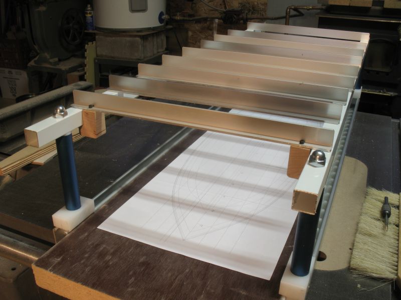
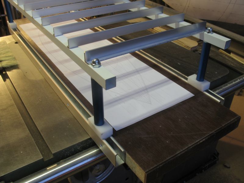
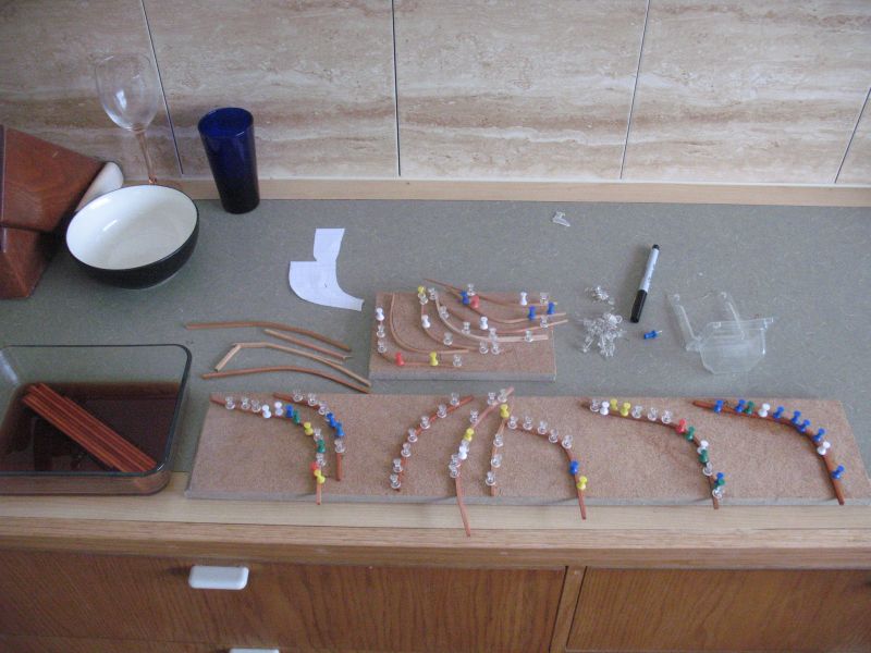
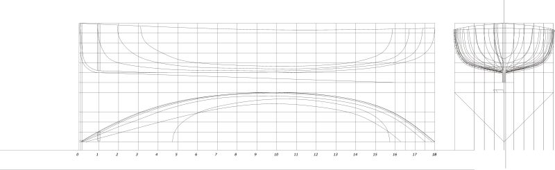
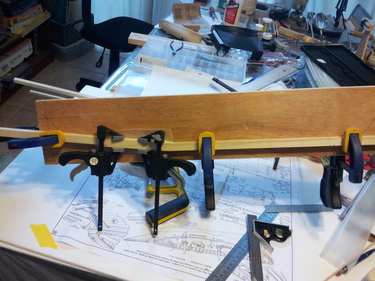
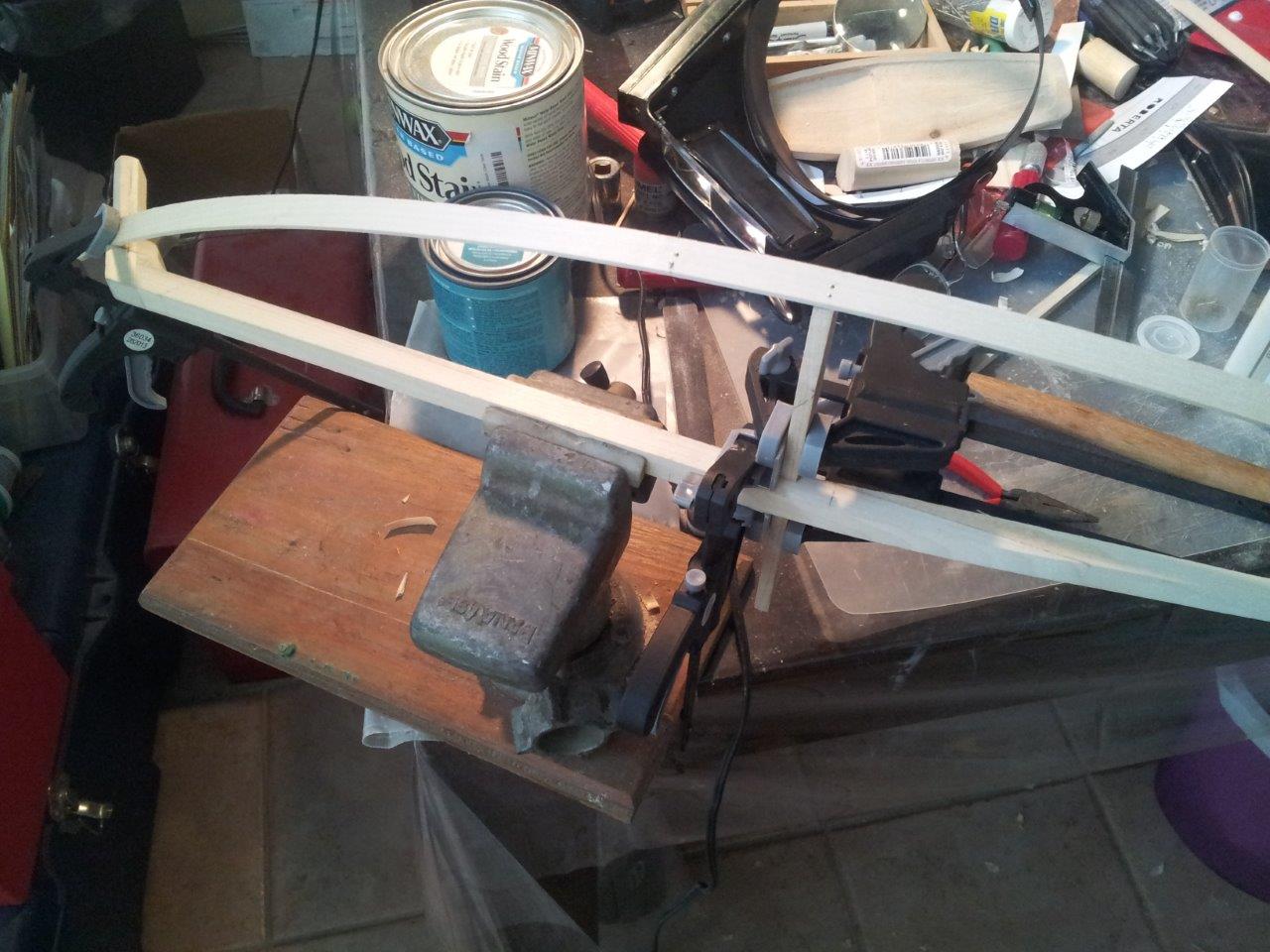
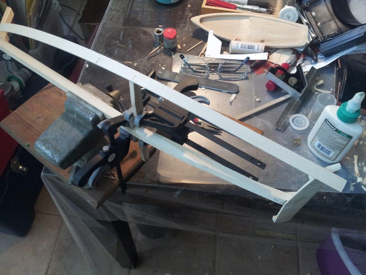
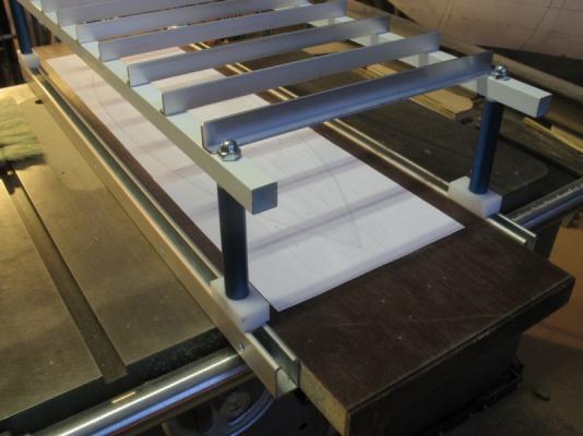
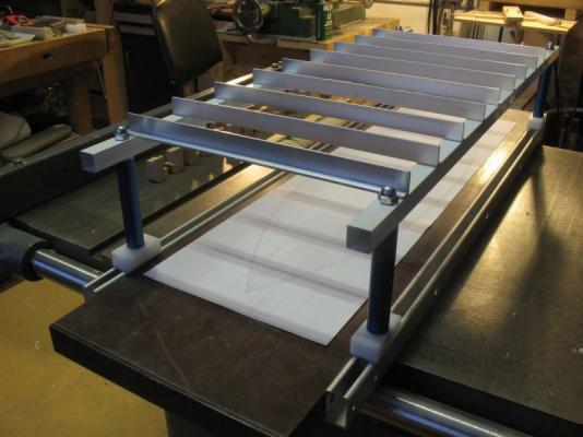
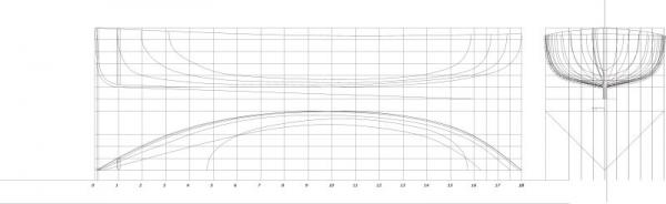
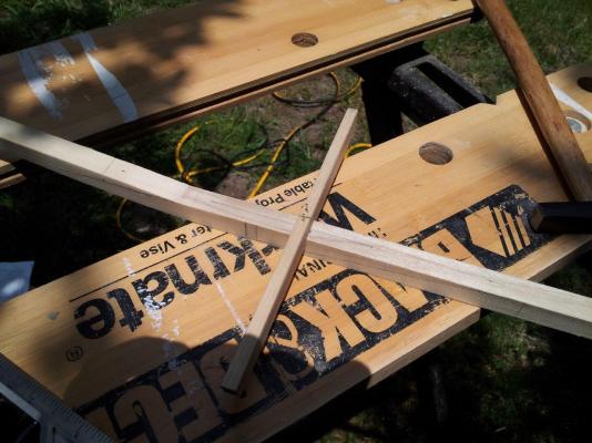
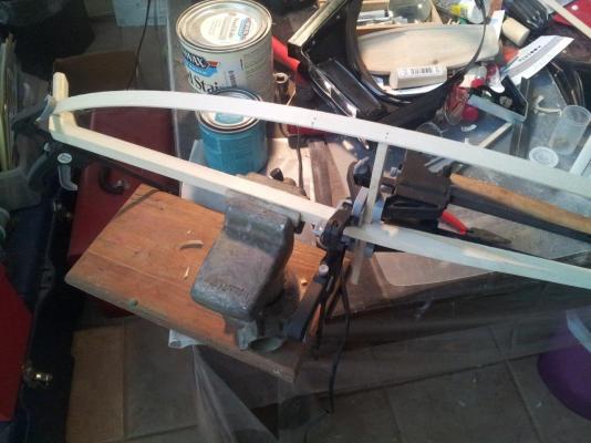
 Floss/Skipjack Part 1 History Floss was one of a pair of Launches that were built in 1909 by Herbert Minett and was powered by a single cylinder Ferro engine, her sister named Skipjack pictured here had a two cylinder Buffalo engine. These launches were built for Andrew Mellon the Pittsburgh Millionaire. Model I am still tracking down information about Floss, and I have a few leads. I am going to build this model the same way as the full size boats of this type were often built. Moulds were suspended from the ceiling in some cases and others were built upside down. The Stem Keel and Stern timbers were set up and the moulds positioned. In either case to build a model using either of these methods I will need to support the moulds and backbone to fix ribbands for setting the bent frames before planking. After the ribbands are fixed to the Stem, moulds and stern the bent frames will be fitted to the keel and then temporarily attached to the ribbands with pins. Once all the frames are set the sheer clamps and bilge stringers and floors will be added. After the basic shell is assembled then the planking will commence. In order to accomplish all this I needed to build a building board with some specific features. Using odds and ends of materials I had laying around the shop I came up with an acceptable solution. The base is 36inches by 10inches by 1 7/32 inches thick it was cut from and old office desk top. The white square tubes are 3/4 inch railing bars left over from a project a couple of years ago. The blue anodized aluminum tubes are also 3/4 inch diameter left over from another project. The white plastic components were machined from some offcuts picked up at a commercial plastic supplier. The aluminum rails are a low cost bar clamp that was cut in half and the clamp mechanisms removed. The dome nuts are 5/16 and are threaded onto a length of 5/16 ready rod that causes the clamps to lock on the rails. The cross rails are a sections of some 3/4 inch U channel that was slit down the middle in the table saw. The cross rails are clamped with some cherry blocks and 4x40 allen head cap screws. These lines are still being reviewed and updated as I get new information, When I am satisfied that they are as good as I can get then the build will actually start. Floss lines.pdf Until then I am getting on with some tests regarding bent frames and testing my ideas about the construction method, and finishing the elements of the building board. Because of scale and look at the large scale of 1:8 the frames will need to be made of something different than oak it is just too coarse. these frames are 1 1/4 scale inches square Fir the wood was boiled for 15 minutes in water. The actual frames will likely be somewhere around 1 1/4 by 3/4 with the inside edges rounded off before bending. I am also testing without heating and just soaking overnight. This will probably be a while in the making and I am in no rush I have lots of work doing the testing and research. it is a great diversion and a break from the intense work on the Pilot Cutter. Plus I needed something to fill in my spare time;>) Michael

-
 Hello all, I'm Reed and this is my first wooden ship build and log. Let me start by telling you the story of how I ended up building this model. My wife and I retired in 2016 and moved to a new home in Cambridge Md. We decided to decorate our home in a nautical/nature theme. We wanted to use decorations that reflected the history and lifestyle of the eastern shore. It was decided that a model sailboat would look good sitting on the mantel. Naturaly, a Skipjack was the model of choice. We spent a good bit of time perusing many of the antique and novelty stores that are so prevelant in our area. There were always a few models for sale but rarely were they Skipjacks. The Skipjacks that we did find were usually folk art/abstract rendisions of the vessel and were very expensive. We wanted a model that was as close to an actual working Skipjack as possible. After seeing a very nicely done model of a Skipjack in a restaurant window, it occured to me that I could build my own. After all, I'm a retired cabinetmaker with over half a century of experience under my belt. "How hard can it be?" , I thought to myself. Well, I was soon to find out. A short time later, I stumbled across a model Skipjack kit at the local Ben Franklin. I bought it for $125.00. It's rated at a "intermediat to advanced" skill level. Since I don't have any experience with other kits, I didn't know what to expect. I will give you a quick review of what I found upon opening the box. First, the kit is made by "Wye River Models" which is a local company located on Kent Island. When I opened the box I found a jumble of sticks. They were not separated or packed by size. There was a materials list that said what each size of wood was to be used for. There was also several sheets of patterns, a bag of pot metal and plastic hardware, two coils of cordage, some aluminum rods, a square of sheet metal, some sail cloth and a few other odds and ends. A nicely done book "The Skipjack" by Steve Rodgers & Patricia Staby-Rodgers was also included to act as instructions. I feel that the book is more of a guide than step by step directions. There were no pre-cut or laser eched anything. Thats when I started to realize that it might be a little harder than I thought. I will add additional commentary regarding the kit along the way. I have put this build log in the SHIP MODEL KITS section because it says "KIT"on the box. After looking through both build sections, I feel that this may be more of a "SCRATCH BUILD" than a kit. I'll let the moderators make the final decision if one is needed. This model isn't one particular boat, rather a rendition of a Skipjack that is built as one of the many would have been built, by ratio. Concidering that there were approximately a thousand of these boats built by differant builders and over the course of sixty years or more, they were not all identical. They varied in length by anything from a foot to over ten. The layout of holds, hatches, rails and rudders (amoungst other things) also varied considerably as well as the construction techneques used to build them. One of the advantages of living in Cambridge is that there are a number of Skipjacks in the area. The Nathan and the Lady Katie are both afloat and docked in town. There are two more that are on land and being restored but I don't know their names. Most recently, the Martha lewis (sister ship of the Lady Katie and the Rosie Parks) was brought to town for what I believe to be repairs and restoration.Two more are just down the road in Woolford. The maritime museam in St. Michaels is a short drive away. They have the fully restored Rosie Parks and at least one other as well as a wonderful exhibit that tells the history of these vessels. It has been a great advantage as I have gone to see these boats on multiple occasions in order to study the fine points of their builds. I actually started building this model in the early months of 2017. I spent many hours working on it as the winter dragged on. When spring came, I put the model aside in favor of outdoor activities. My intent was to start again the following winter (2018) but my wife had other plans for my time. Constructing the cabinets for and remodeling the kitchen took up that time. Once again warm weather arrived and the model remained on a shelf collecting dust. Shortly after last Christmas, I found myself with free time and started back on the build. I have, up until this point, completely built this model on my own and am currently almost done building it. However, after recently discovering this site, I have now decided that some things need to be done better. Using my newly developed skills and some of the techniques exhibited here, I hope to bring the quality of the model "up a notch"....or two. I'm looking forward to the opinions and help I know I can get here.
- 82 replies
-
- 6
-
-
- skipjack
- wye river models
- (and 2 more)
-
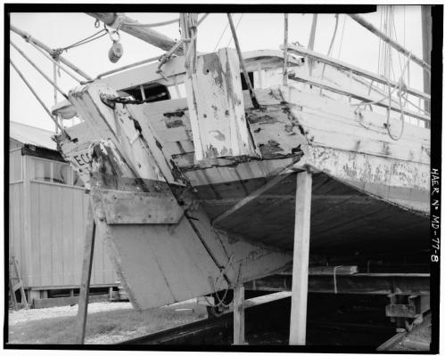
 Skipjack Kathryn Part 1 – Background I’ve always liked the lines of the Skipjack oyster dredging craft from the Chesapeake Bay. A couple of years ago I found drawings of the Skipjack Kathryn on the HAER website, and thought this would be an interesting build. Kathryn was built at Crisfield, Maryland in 1901. Kathryn is fairly large for a Skipjack, measuring 50 feet long and 16 feet 8 inches wide. The HAER documentation includes the information that was provided for the nomination of Kathryn as a National Historic Landmark, and indicates that Kathryn is the oldest of the true “skipjacks” - the two-sail bateau built expressly for the oyster trade. Kathryn’s hull is a modification of the standard hard chine skipjack design. The hull has the same general form as the standard skipjack with a sharp convex bow, beamy midsection, and counter stern. The difference is that Kathryn is planked fore-and-aft with a rounded chine rather than having a hard chine and being planked athwartships in a herring-bone pattern. Only a small number of skipjacks have been identified with the same construction – the Susan May (1901) and Maggie Lee (1903) among them. Kathryn carries the traditional Chesapeake longhead or clipper bow with a straight raking stem. Kathryn underwent a major rebuild in 1954, which included the deck and siding, but retained her original form and many of her original oak timbers. The HAER documentation was recorded as Kathryn existed in 1995. Some modifications had been made to Kathryn’s outward appearance, mainly the addition of a ‘doghouse’ or companionway above the main cabin, and the replacement of the forepeak hatch with one of a lower profile. In 2011 Kathryn struck a buoy during the annual skipjack race off Deal Island, Maryland. “Stoney” Whitelock, the current owner and captain, said “When I hit that buoy, that was no big deal, but I found out there was no nails holding the planks onto some of the frames, they were eaten away. Almost all of the frames at some point were rotten.” A major construction project was launched to rebuild Kathryn, starting in 2011 under the guidance of Mike Vlahovich – a master shipwright and founding director of the Coastal Heritage Alliance. The project was funded through grants and private donations, and much of the reconstruction work was performed by volunteers. Kathryn was relaunched during the end of September 2015, and worked the 2015 oyster season. I was able to spend a short time on board Kathryn during October 2015 as she was docked at Deal Island before the oystering season.
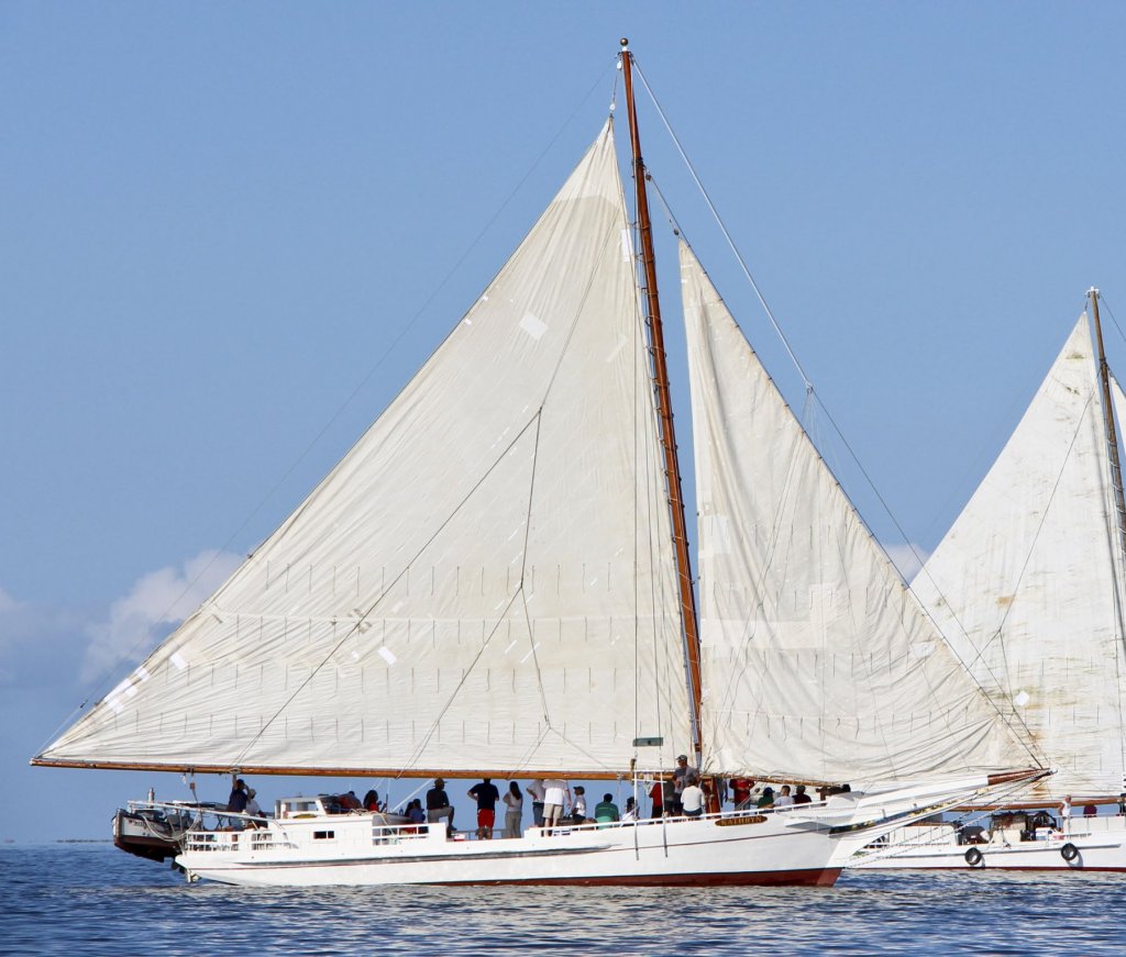
- 878 replies
-
- 25
-
-
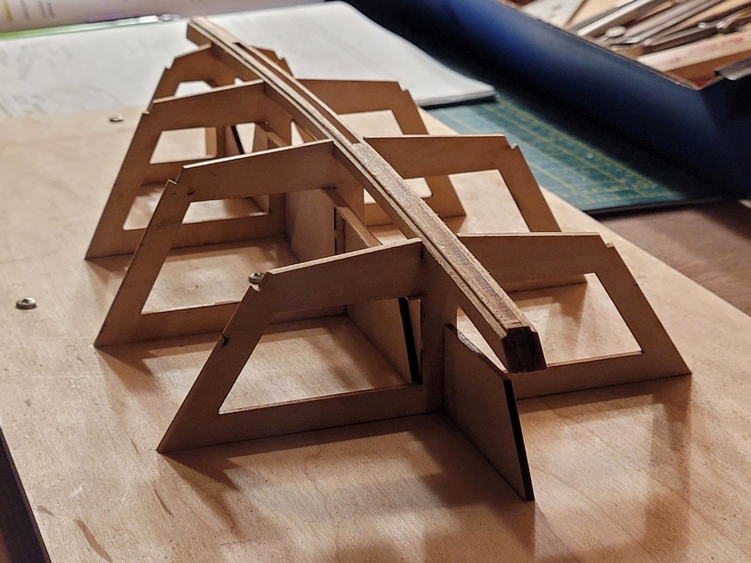
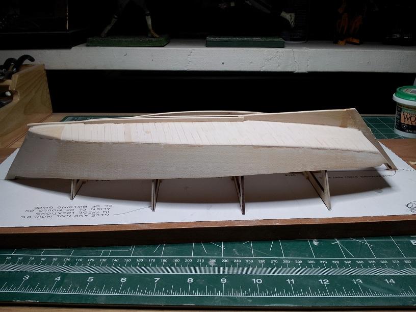
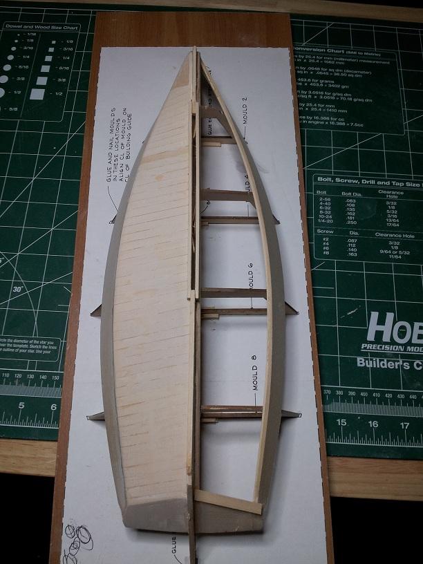
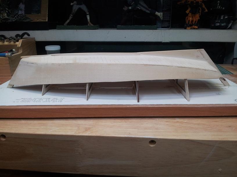
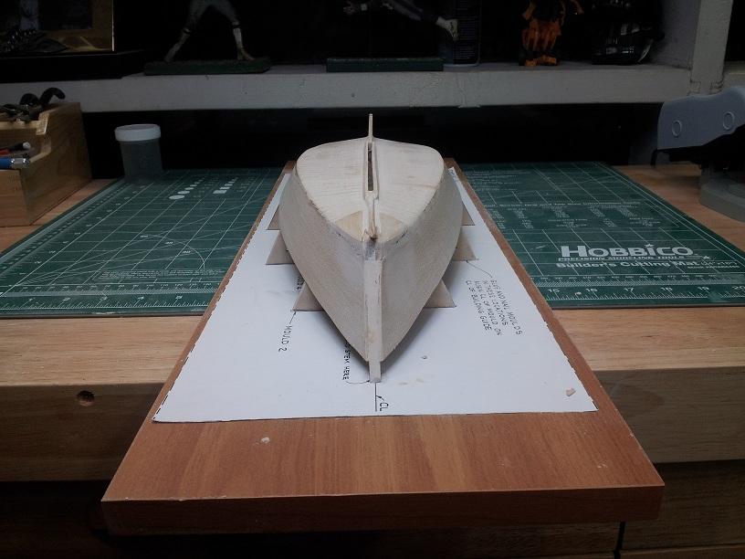
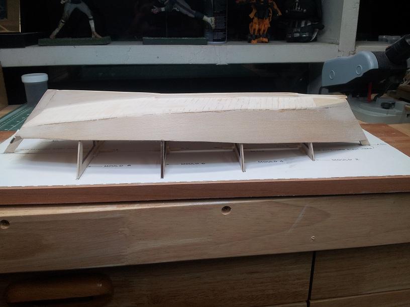
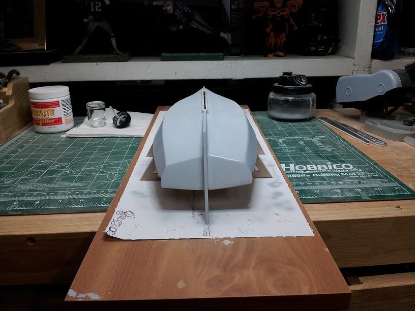
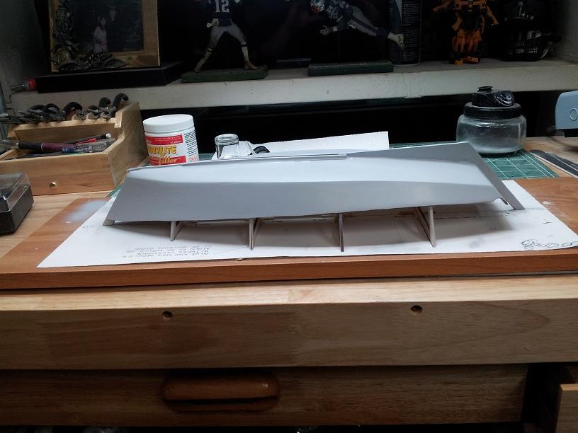
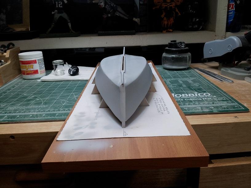
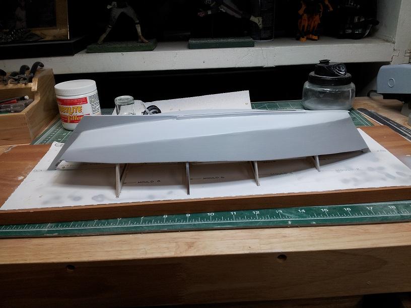
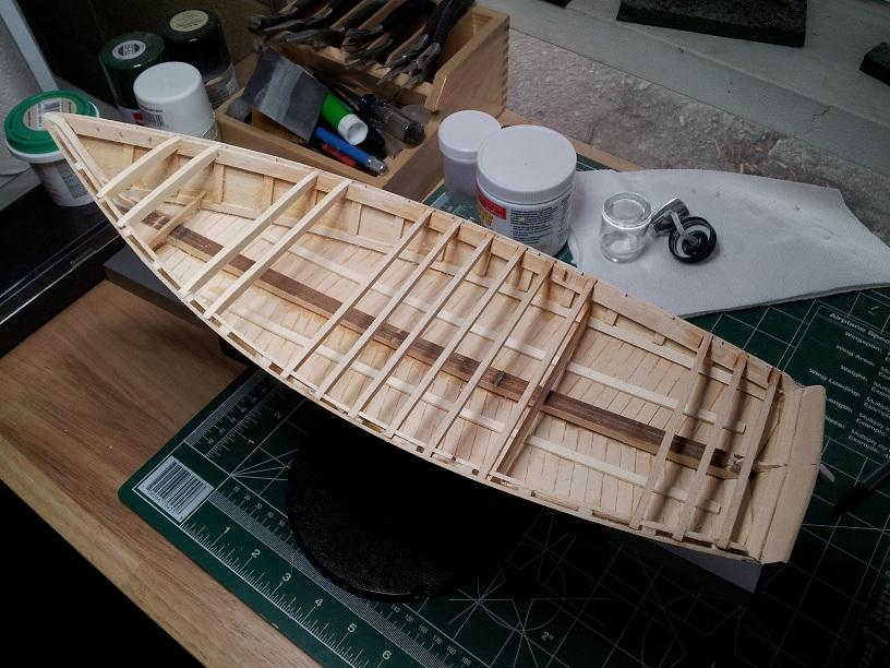
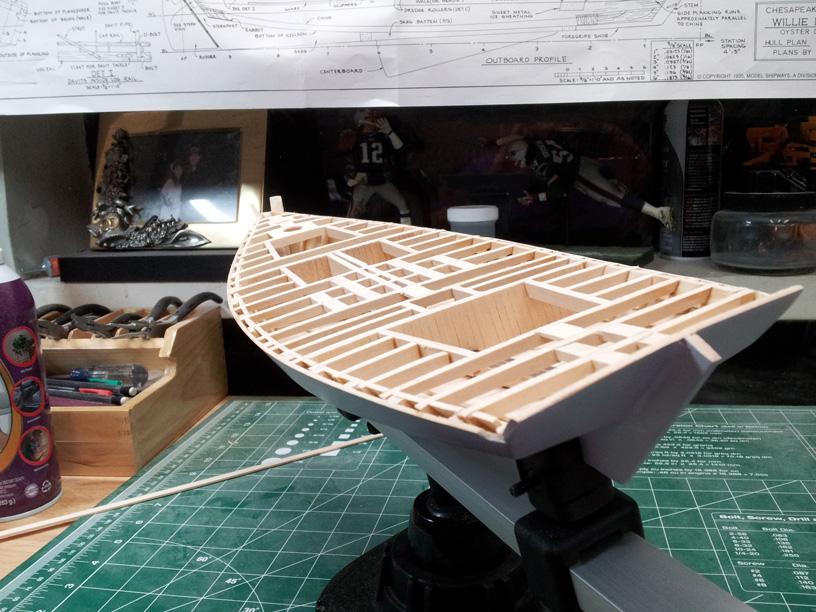
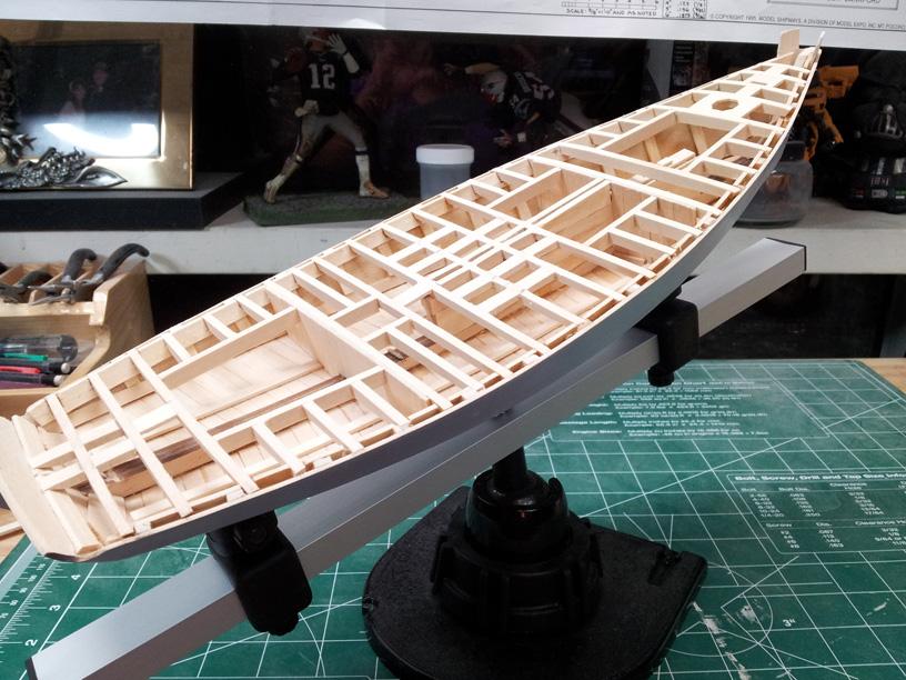
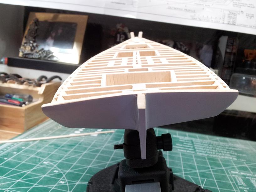
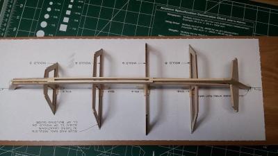
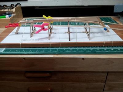
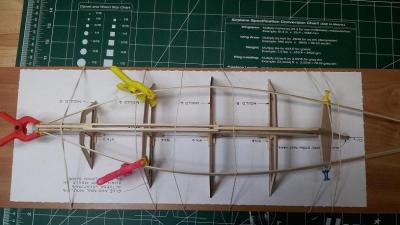
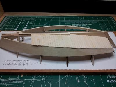
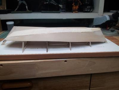
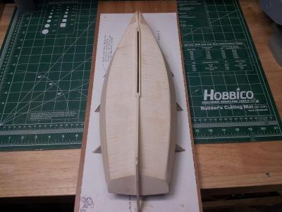
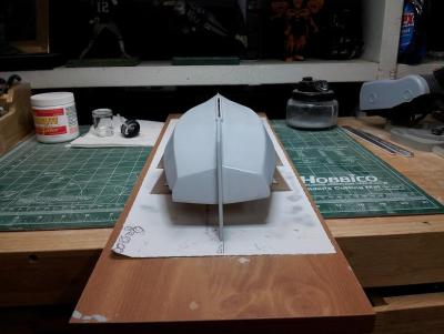
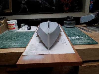
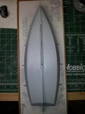
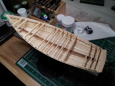
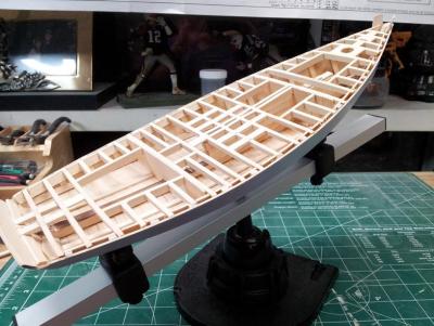
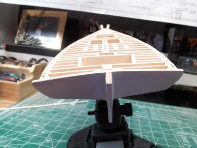
 Greetings All!! This is actually my second undertaking. My first was the Phantom which I will be putting up shortly. This was a Christmas Present from my lovely wife, and as such had to cut ahead in the Ship queue. We start with the traditional unboxing. We begin with the documentation which consists of one manual, a parts manifest, 2 large plan sheets and an errata sheet. The model is kind of a hybrid POF/POB so the contents consist primarily of strip stock, raw brass, and some laser cut sheets as well as various white cast parts which appear at first glance to be of decent quality and useable as is. Finally the normal supply of blocks, string and normal ship fittings. The instructions are not too too bad. It is quite informative with history anecdotes as well as examples of how the real ship is built. The trouble is these are intermingled with instructions on how to build them in the kit and they tend to get muddled at some points. I like the information however, being a novice, I found it confusing at points. To kick off the build a template needs to be attached to a build board which will be used to set up the build molds. I just grabbed an old particle board shelf as the build board and using a glue stick attached the template. I think next time I will use rubber cement to make it semi-permanent because at the moment I am having issues getting the template off of the board - and would like to reuse it as it is a very nice build board =). Once the template is down it is just a matter of attaching the laser cut build molds to the build board using the template as a guide. I added some spars at the base to stabilize the molds and give them some reinforcement. Once all of the molds were in place and proven square it was time to attach the keelson and chine logs. This was very straight-forward, no muss no fuss. The next part is construction of the hull shell itself. The side planks are a single piece of wood cut to follow the chine logs, bent to shape and attached stem and stern. Remember, do NOT glue them to the molds - that would be very very bad. If you should by accident you can carefully pop them off when it is time to separate the shell. *You can, to avoid getting glue stuck to the molds place some wax over them. Once you get the sides in place, time to lay the planks along the bottom of the hull. Again, pretty straight-forward. Cut and place the planks up to the chunk, place the chunks, sand and shape and walla! One Willie Bennett hull shell!! Sand, sand, sand and sand!! I went ahead and primed mine prior to removing it from the molds but there is no requirement to do so, I just wanted to be sure my hull was as finished as possible before flipping it over. Once the shell is complete and removed from the build molds it is decision time!! The next step is the deck framing. There are two ways given to go about it, the first is a basic framing and the second is a "realistic" framing. The main reason to do the second is if you want to build the ship as close to the real thing and/or plan to have it opened up or have some of the interior visible. If the latter is not the case, the basic framing is more than adequate as it just needs to support the decking. I opted to do the realistic framing including the blocking, more so for the experience than anything else. I did not however detail the bunk areas or the internals of the different wells since the ship will be in a display case and not easily accessible to move and scrutinize close enough to see the detail. The next four pics are of the framing, the first pic is actually partial framing prior to deciding which way to go. At that point I could have gone either way. The last three are the framing completed and ready for the plankshears! The BIGGEST tip I can give at this point, regardless of which style you decide to do - make sure you mark and cut the notches in the clamps which hold the deck beams PRIOR to attaching them to the hull. It is doable after they are attached, but much much easier to do after the fact - so I found out =( From here, I had to break. I was working on the plank shears trying the cuts to get a nice curve and well - let us just say I have some more practice needed! I chewed up a fair amount of wood trying to get them right so had to replace the wood. To keep working I did some work on another kit while waiting to be able to pick up the wood at which point will return to the Willie. that will be tomorrow 😃 Thank you for popping in!! And as always - whatever you do, and however you do it... enjoy it!! -Adam
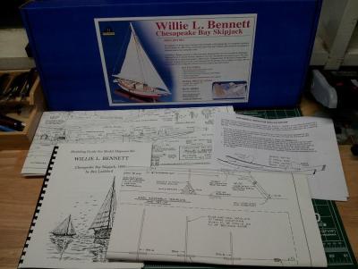


- 97 replies
-
- 2
-
-
- Willie L Bennett
- SkipJack
- (and 2 more)
-
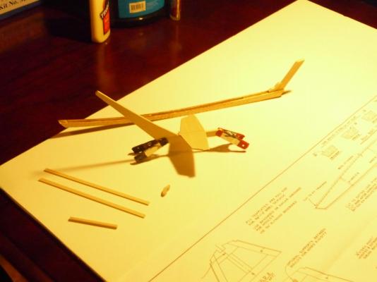
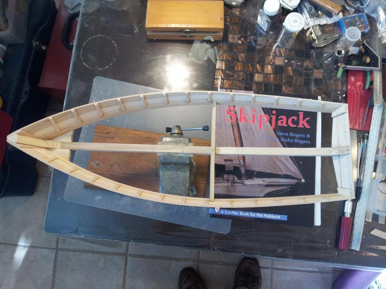
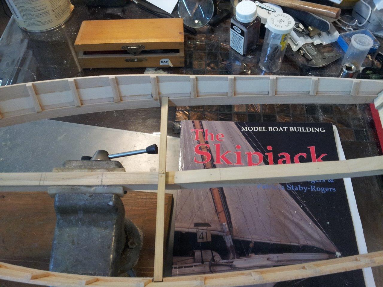
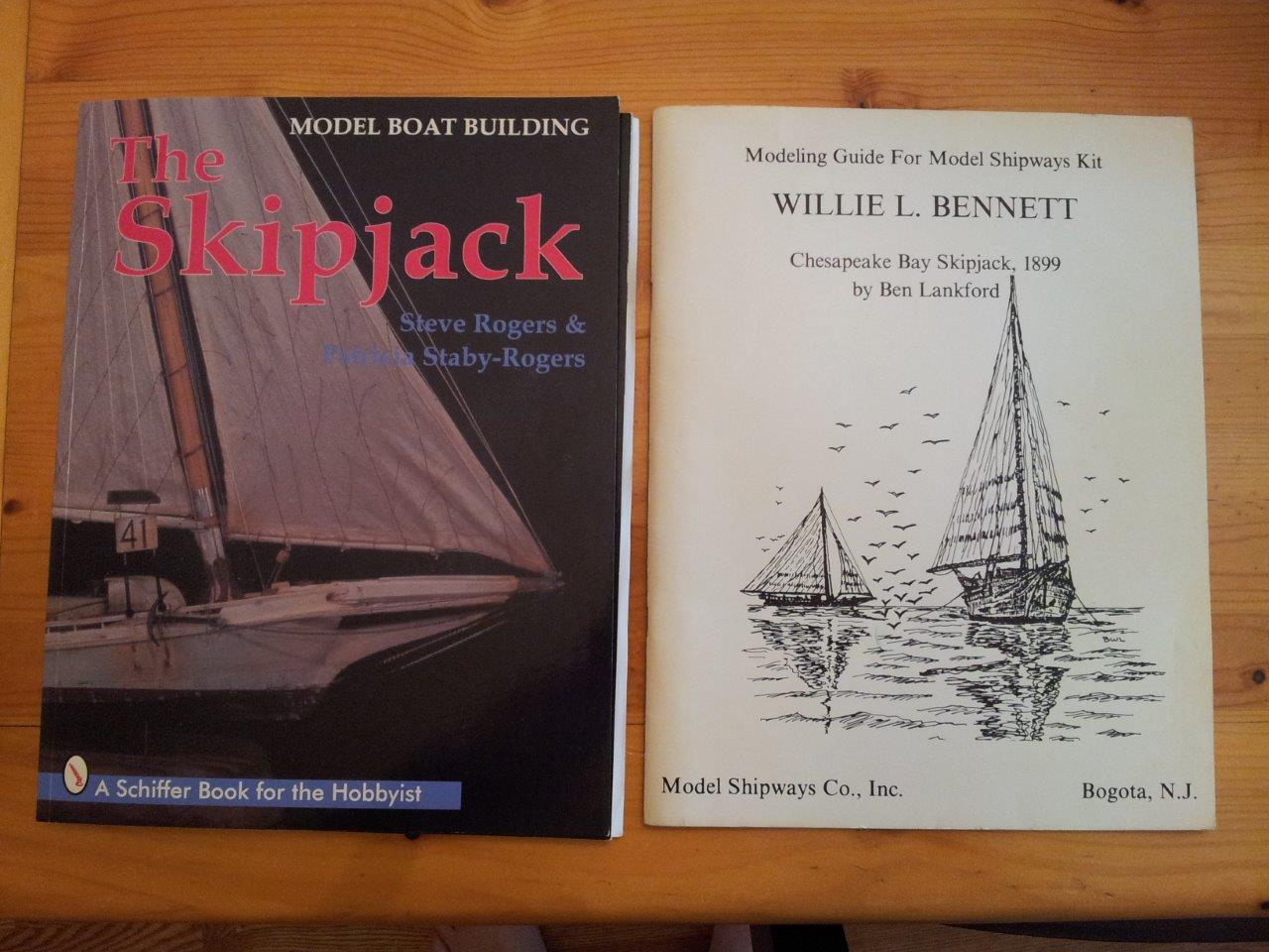
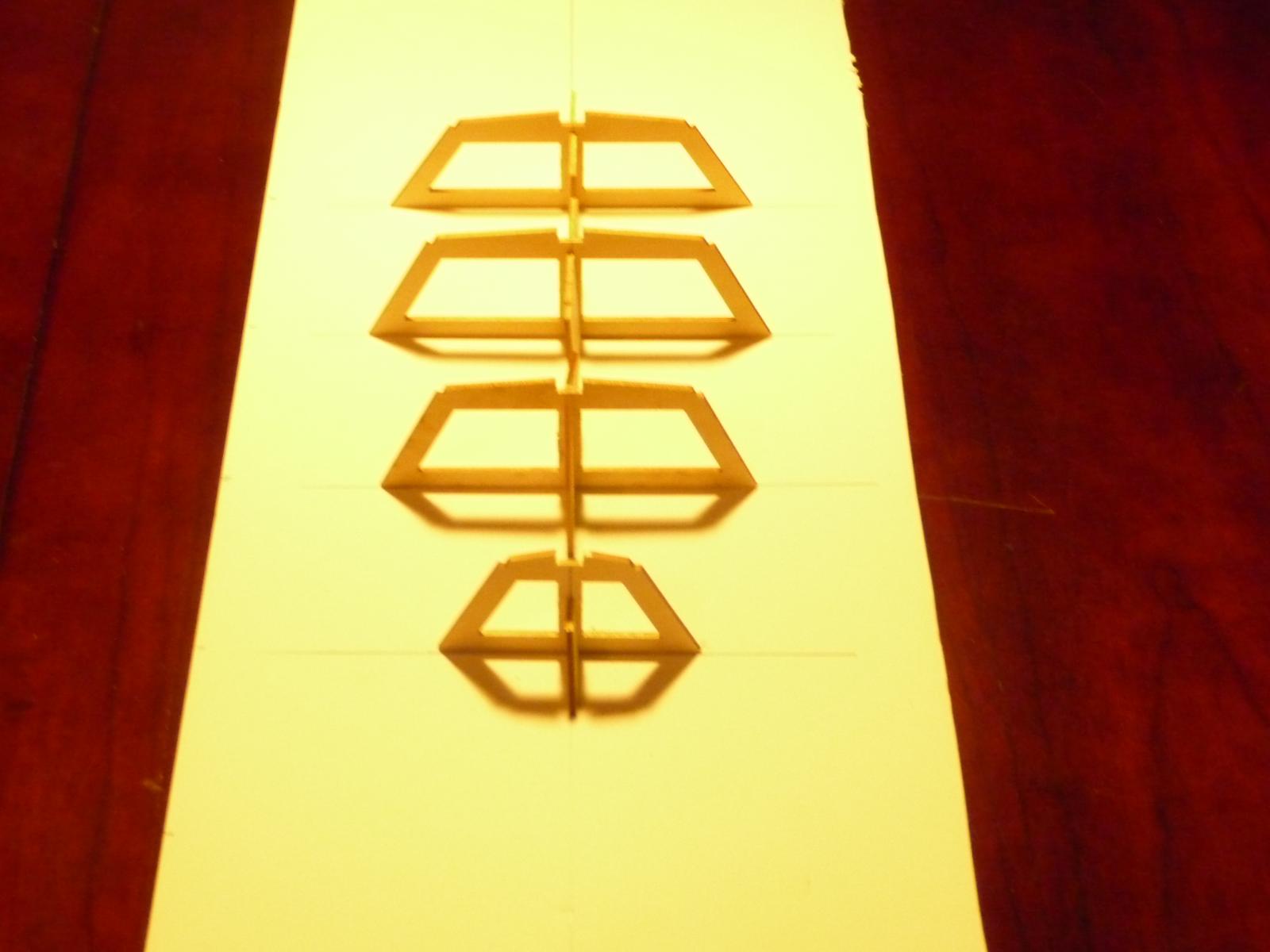
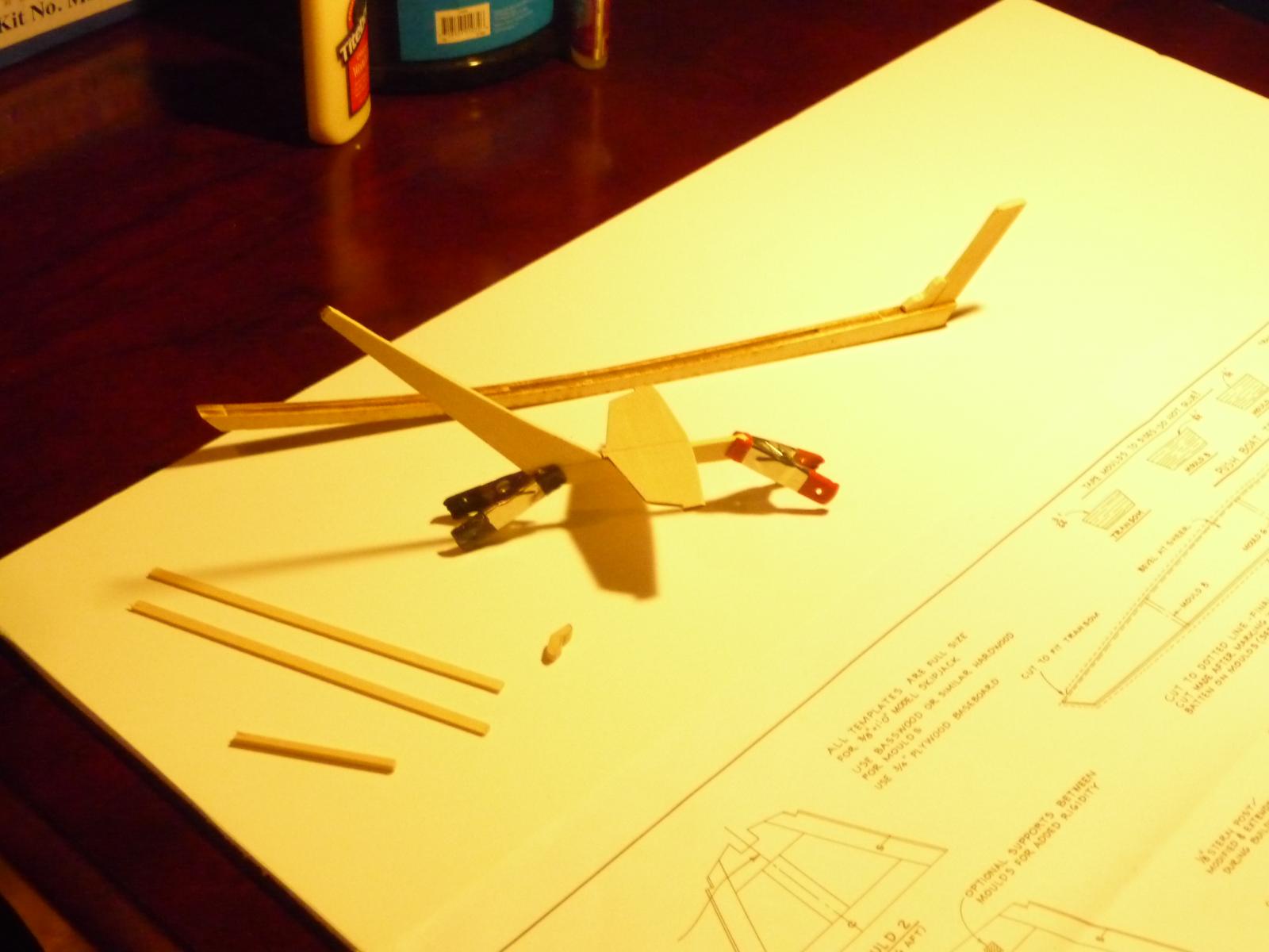
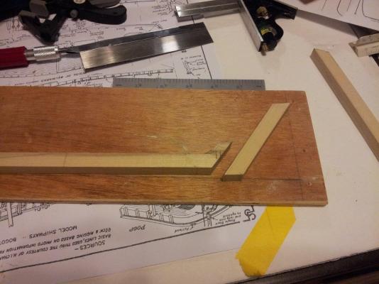
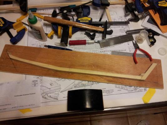
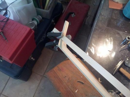
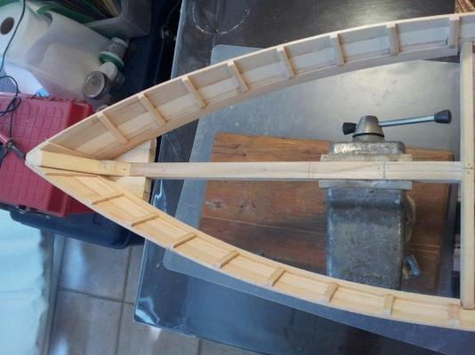
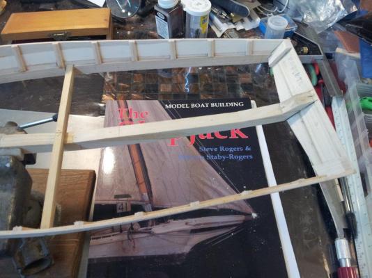
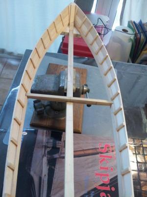
The skipjack is a traditional fishing boat used on Chesapeake Bay for oyster dredging. Skipjacks vary in size, usually 40 – 60 feet in length. They were not built from plans. Almost every dimension of the hull and rig is a ratio of the length of the hull. Several weeks back, my wife and I went to the Reedvillle Fisherman's Museum in Reedville Virginia. They have a skipjack, Claud W. Somers, a deck boat, Elva C., a replica of Captain John Smith's barge (circa 1608) and what remains of a Chesapeake Bay Log Canoe. It is a small museum with lots of models, model train layout and a boat yard. While perusing the gift shop I came across Steve Rogers, Patricia Staby-Rogers book “Model Boat Building: The Skipjack” and bought it. I was already working on MS Phantom, but I kept going back to this book. So here is my build log for a 45ft skipjack. This is my first scratch build model. My primary source is the book “Model Boat Building: The Skipjack”. For reference and additional information I am using the plans for the MS Willie Bennett, Ben Lankford's book “Modeling Guide for Model Shipways Kit willie L. Bennett” and a spreadsheet I found on line at http://msuweb.montclair.edu/~lebelp/Miscellany.html. The spreadsheet has the dimensions ratios used to build skipjacks and has come in very handy. “Model Boat Building: The Skipjack” talks about the ratios that are used to calculate the skipjack dimensions, but no where in the book are they listed. The books I am using for reference. Cutting the keelson. Gluing the keelson. Adding the stemliner and the transom. Attaching the strongback. The strongback is nailed in place and will be removed after the bottom planking is completed. There was no specific location given for the strongback so the placement was based on the Willie Bennett plans. Adding the first plank. This is where you determine the shape of the hull. The side planking completed. Edited to add links


-
I am interested in building a model of a Skipjack oyster boat. How does the Midwest Products kit compare with the Model Shipways Kit No. MS2032 in terms of completeness, quality of components and instructions, etc.? Are there "better" kits available than these two? While I am new to wood ship model building, I plan to build 1 or 2 simple wood models before tackling the Skipjack, so building skill should not be a problem. Thanks, in advance, for your help with this. Tony
-
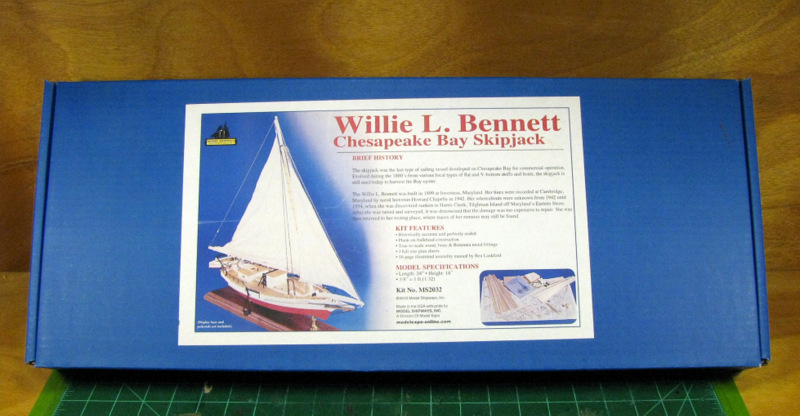
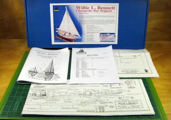
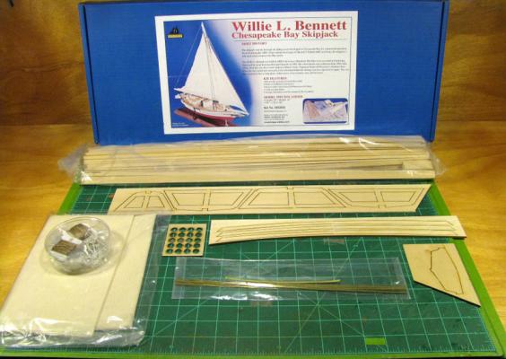
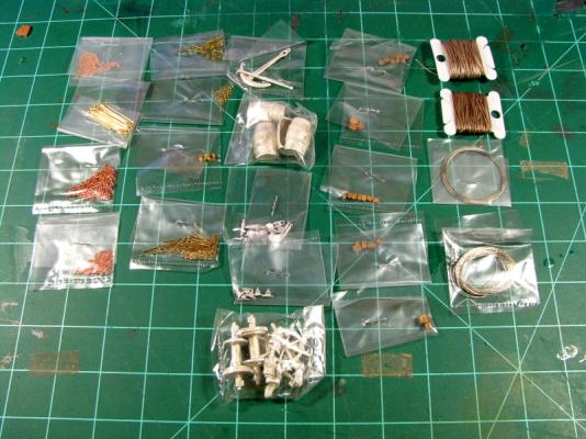
 First, let me say I have already found this forum to be an invaluable resource for both the neophyte ship modeler and the experienced builder. To that I offer a big... THANK YOU ! ...to the owners and administrators of Model Ship World and everyone else who has taken time to share your knowledge, experience, and wisdom on this forum. Thanks Folks! Now on to some business... Although not my first boat build, this is my first wooden sailing craft build. I've been working on a scale model Dodge Runabout (Legend Model Boats) for several months now (see link in my signature). Its coming along nicely but I still wanted to try my hand at a sailing boat. As for experience, I've been into model building in general since I was a kid and have been fooling around with model railroad stuff for nearly 40 years – mostly HO with a smattering of On30. I prefer working with wood and build mostly kits, but do a little scratch building too. In choosing my first sailing craft build, I thought something rather basic might be in order, so after looking over a lot of stuff I decided on the Willie L. Bennett Chesapeake Bay Skipjack by Model Shipways. Why the Bennett? First, Model Shipways and Model Expo seem to have a topnotch reputation in the model ship business. Second, I like the larger scale, the smaller price tag, and it does seem to be a tad less complicated than, oh say, Nelson's Victory or something on that order... So we'll start with the obligatory “the box and what's in it” shots... After unpacking, ran through the parts list – everything looks good there. I retrieved the plans and instruction booklet and will spend the next week or so studying this stuff and getting a little more familiar with the pieces, parts, and process. Should get started on this thing for real in a week or so. Until then...
- 43 replies
-
- 3
-
-
- Model Shipways
- Skipjack
- (and 1 more)
-
 Built the frame to build the hull around. Build the Keelson, Stern Post, Skeg, and cut out a few other peices to join the Keelson together. This will be slow going since this is my first build and I am taking my time. I really don't want to frustrate myself right out of the gate. Rich