Search the Community
Showing results for tags 'Whaler'.
Found 6 results
-
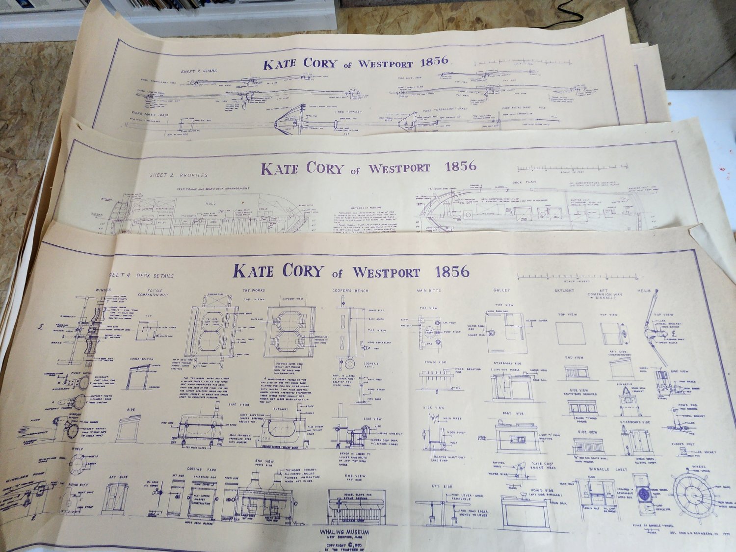
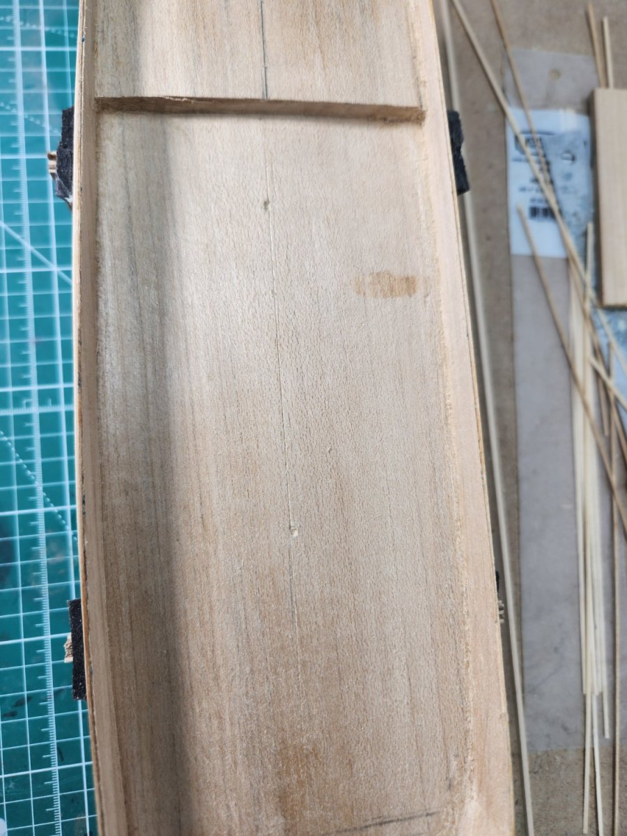
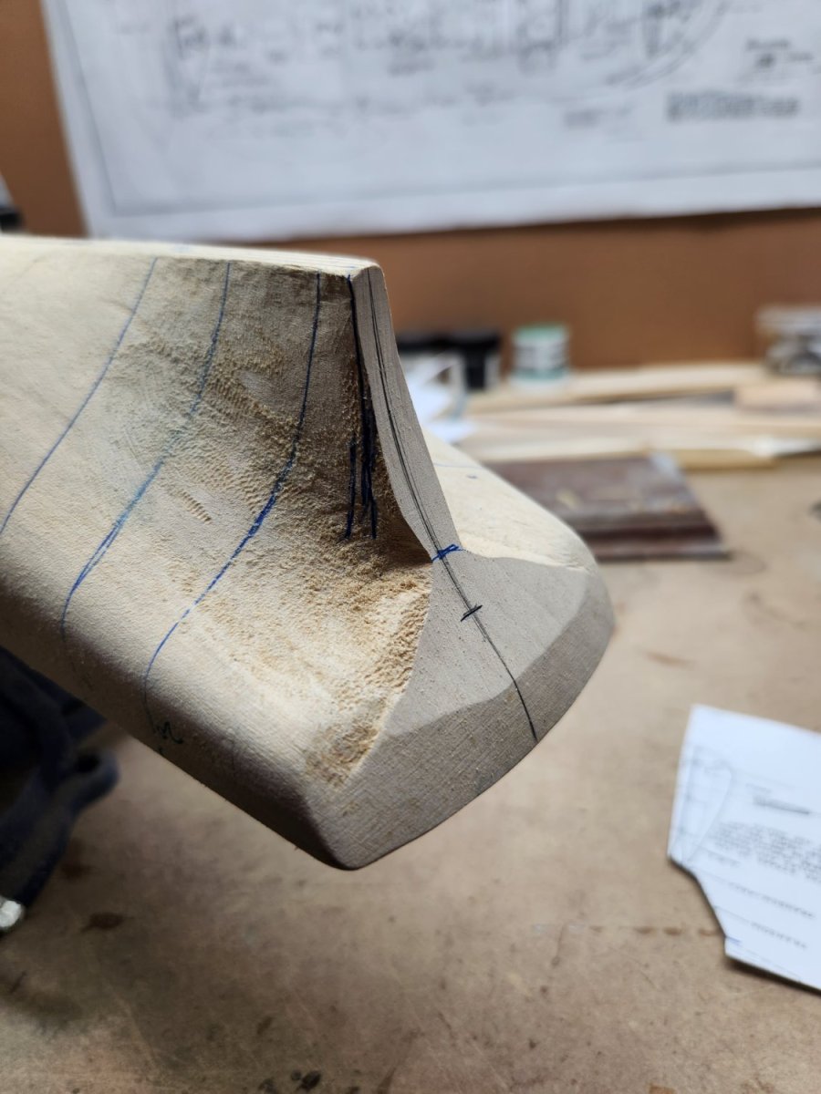
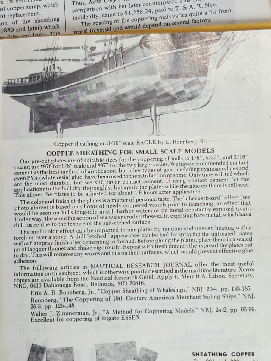
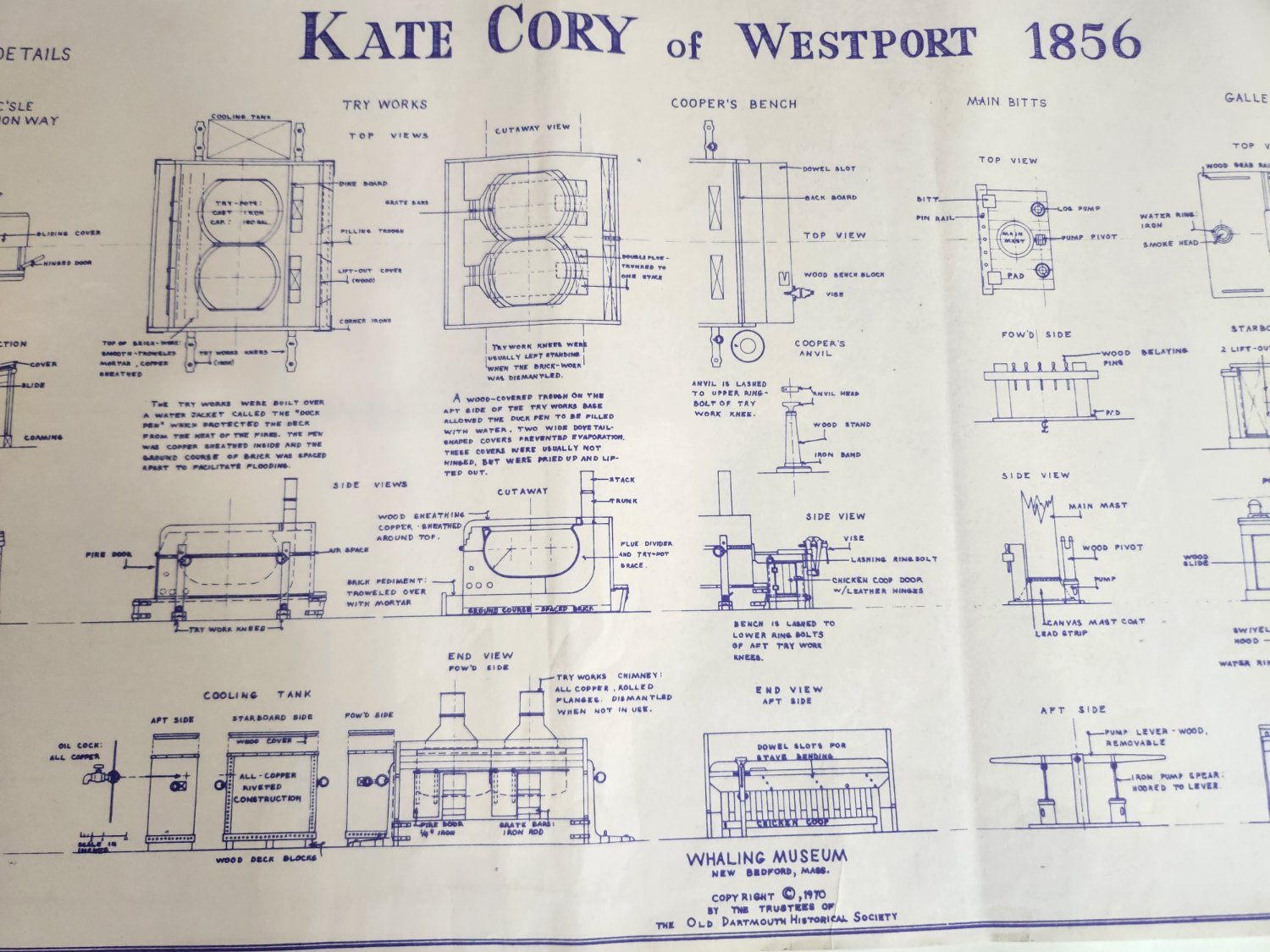
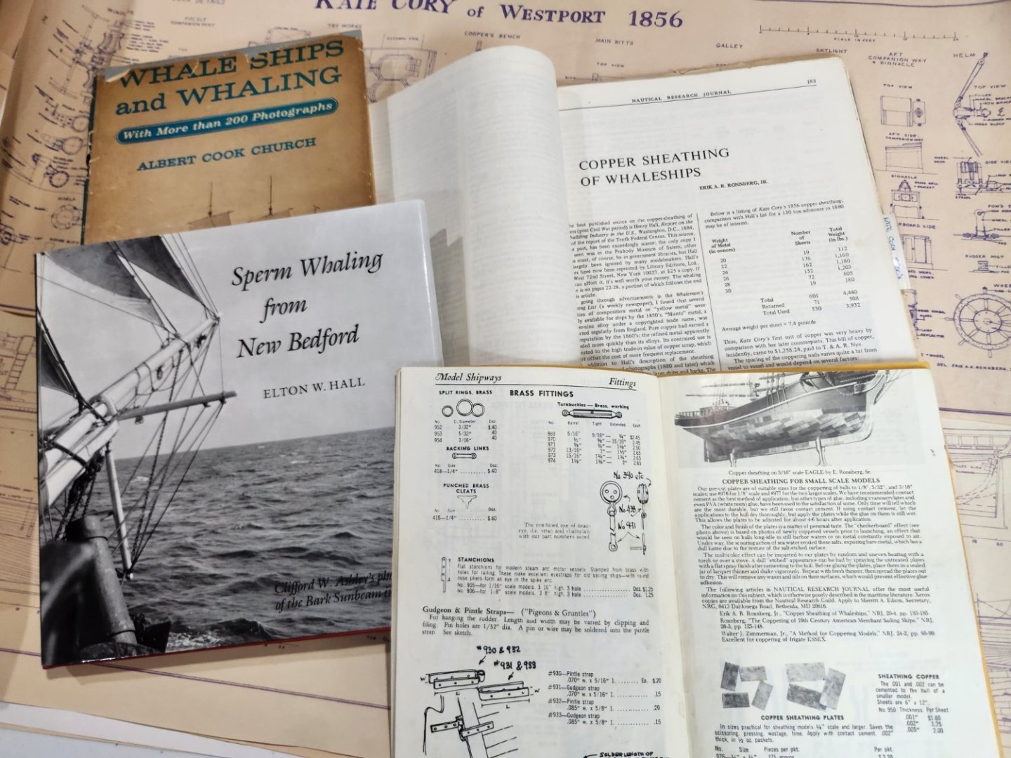
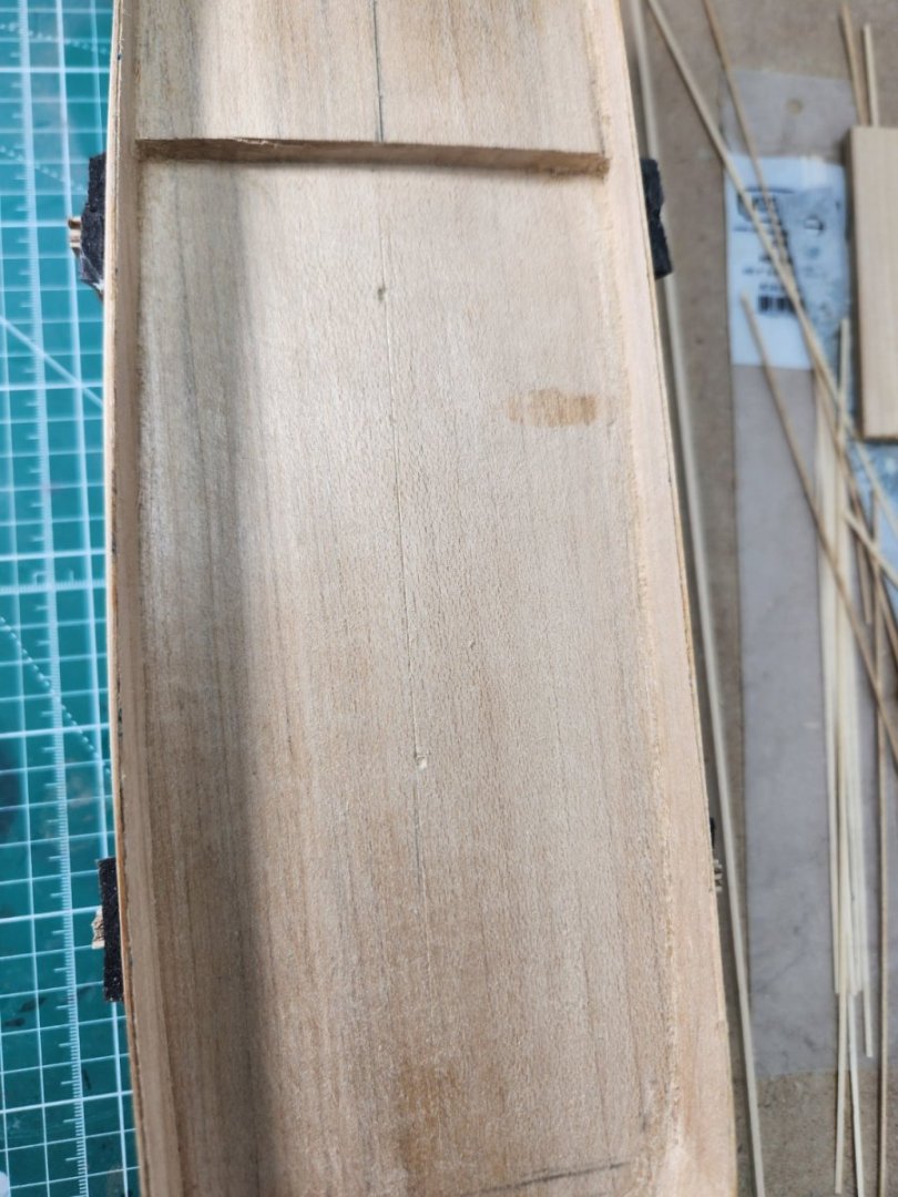
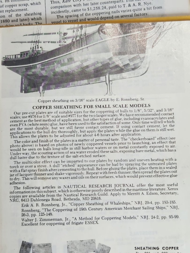
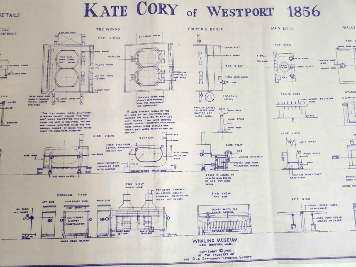
 Bought this kit along with a set of plans from New Bedford Whaling Museum many years ago and finally decided to build it. I saw the kit listed in the first Model Shipways catalog I received in 1986 when I was considering the hobby. I decided on a starting with their KATY, 1/4" scale Virginia Pilot Boat. Since then, I have built several other kits along with my other hobby interests. However, completing the Kate Cory has always been one of my primary ship modeling goals. Unlike the Charles W. Morgan, there is not a great deal of historical documentation available regarding this specific ship. The New Bedford Whaling Museum, New Bedford, Ma. (USA) is the only resource I could find that offered credible documentation. This is where I obtained plans by Erik Ronnberg, Jr. which provide significantly more details and views then the kit plans. Additionally, I obtained copies of the Nautical Research Journals referenced in the Model Shipways Catalog regarding Coppering techniques, i.e., "Copper Sheathing of Whaleships", etc. I coppered two other kits using this technique and feel it provides a more realistic appearance. However, one could argue using this process without some weathering of the rest of the model is inconsistent. Despite all the research and obtaining all the documentation I could find, I still felt I needed a good visual representation of the ship. Finally, a key motivating factor for me to starting the project was the 1/4" scratch-built model by Thomas J. Lauria, (https://tjlauria.com/gallery/whaling-schooner-kate-cory/). Tom has many other excellent builds and has been helpful answering my questions. This will be a planked solid hull model. I've never built a plank on frame kit other than a small Dory. Then only other change from the kit is to swap out the solid wood whale boats for a set of updated laser cut boats.
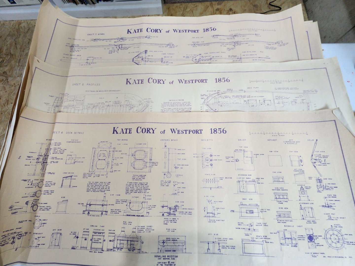


-
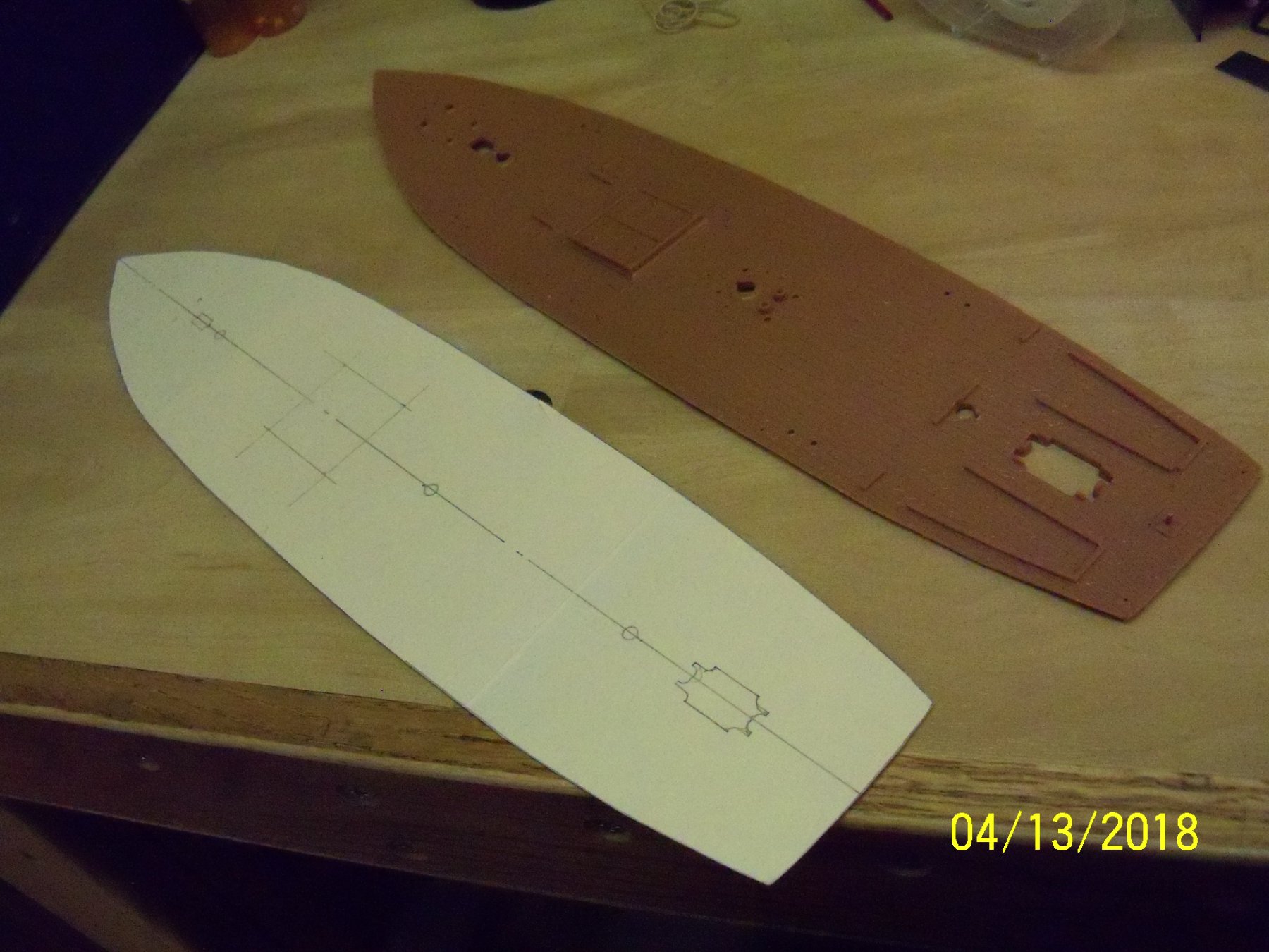
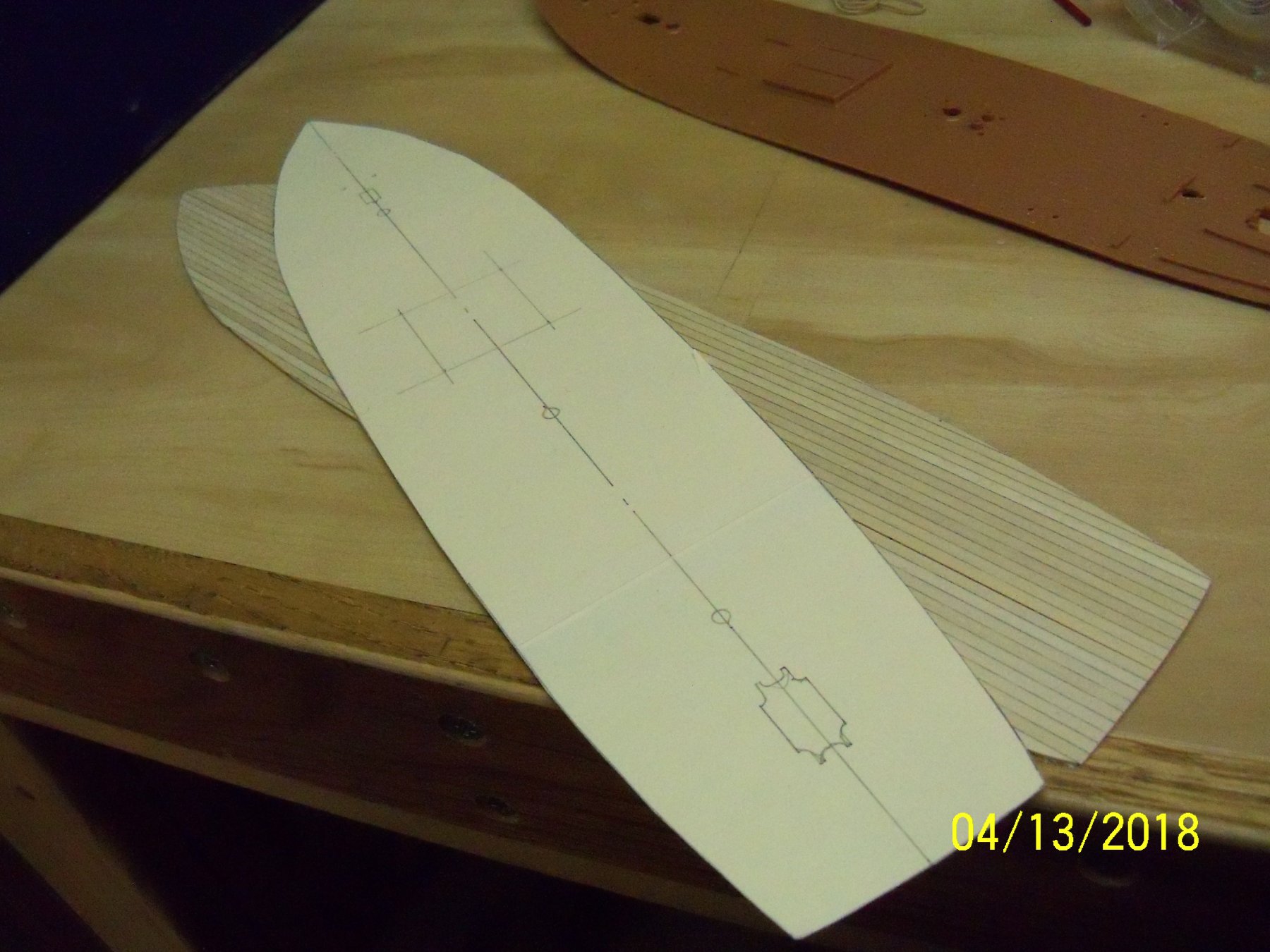
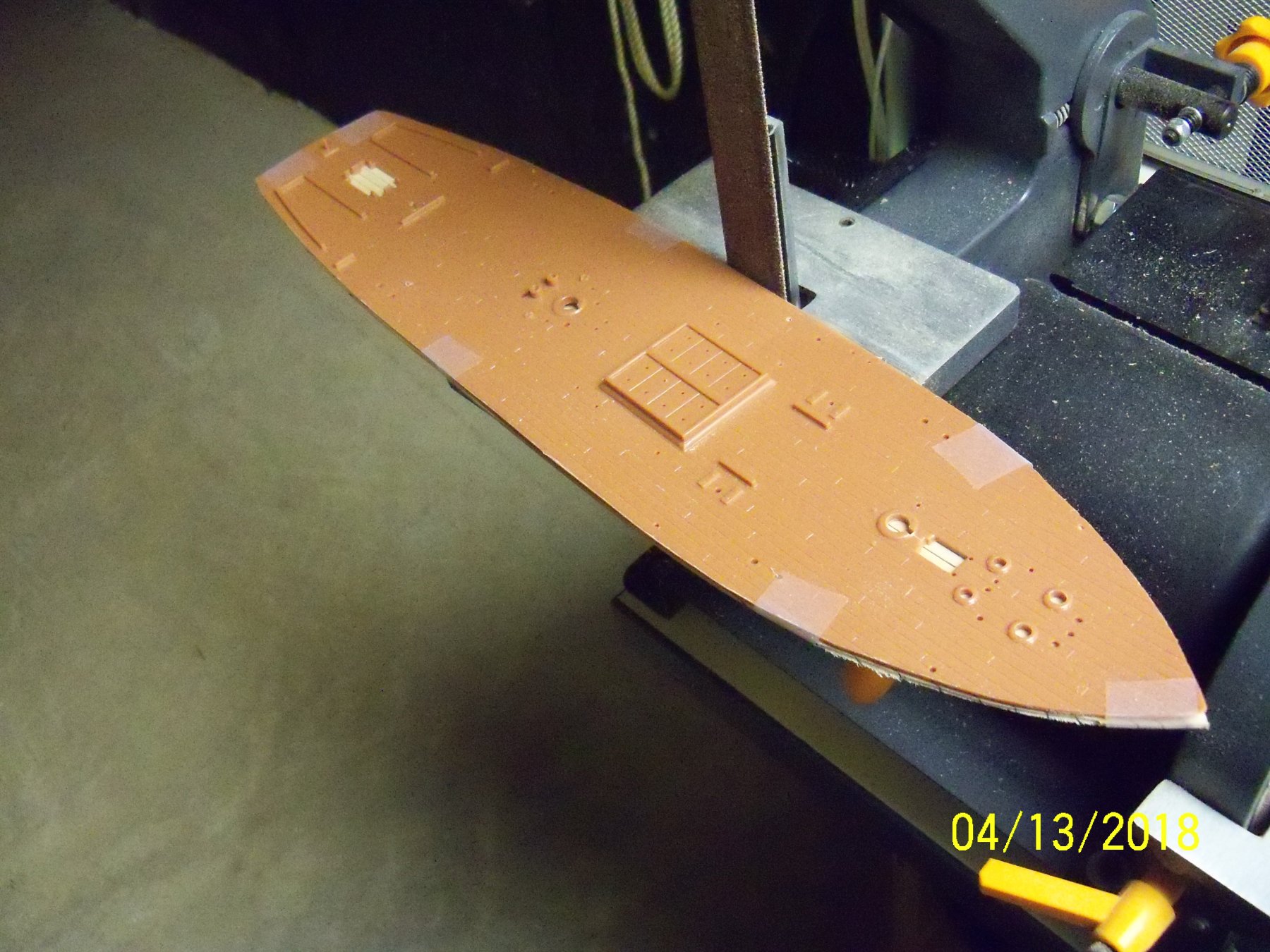
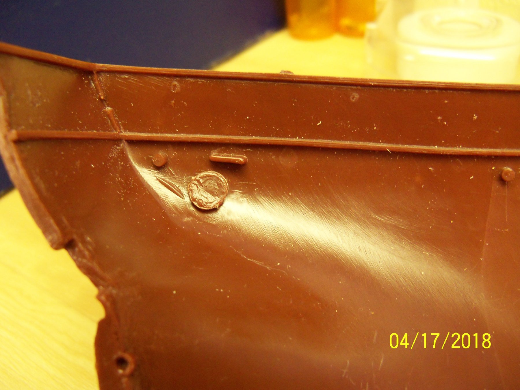
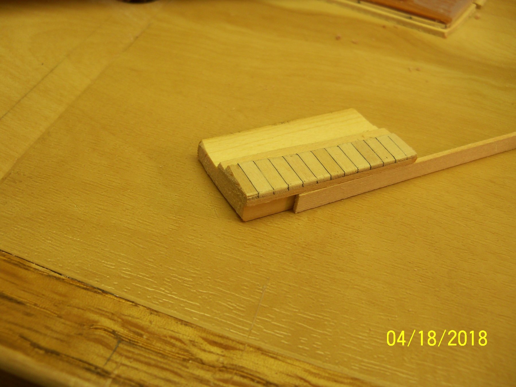
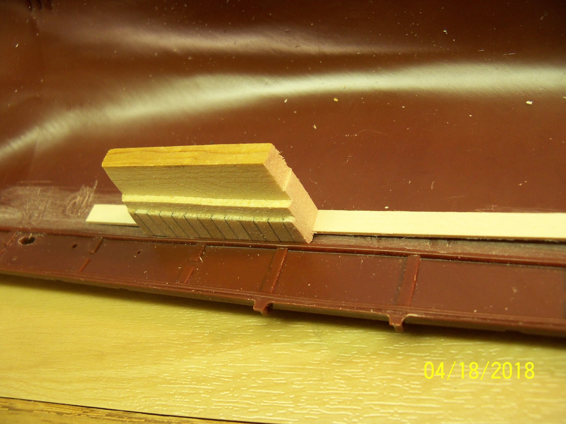
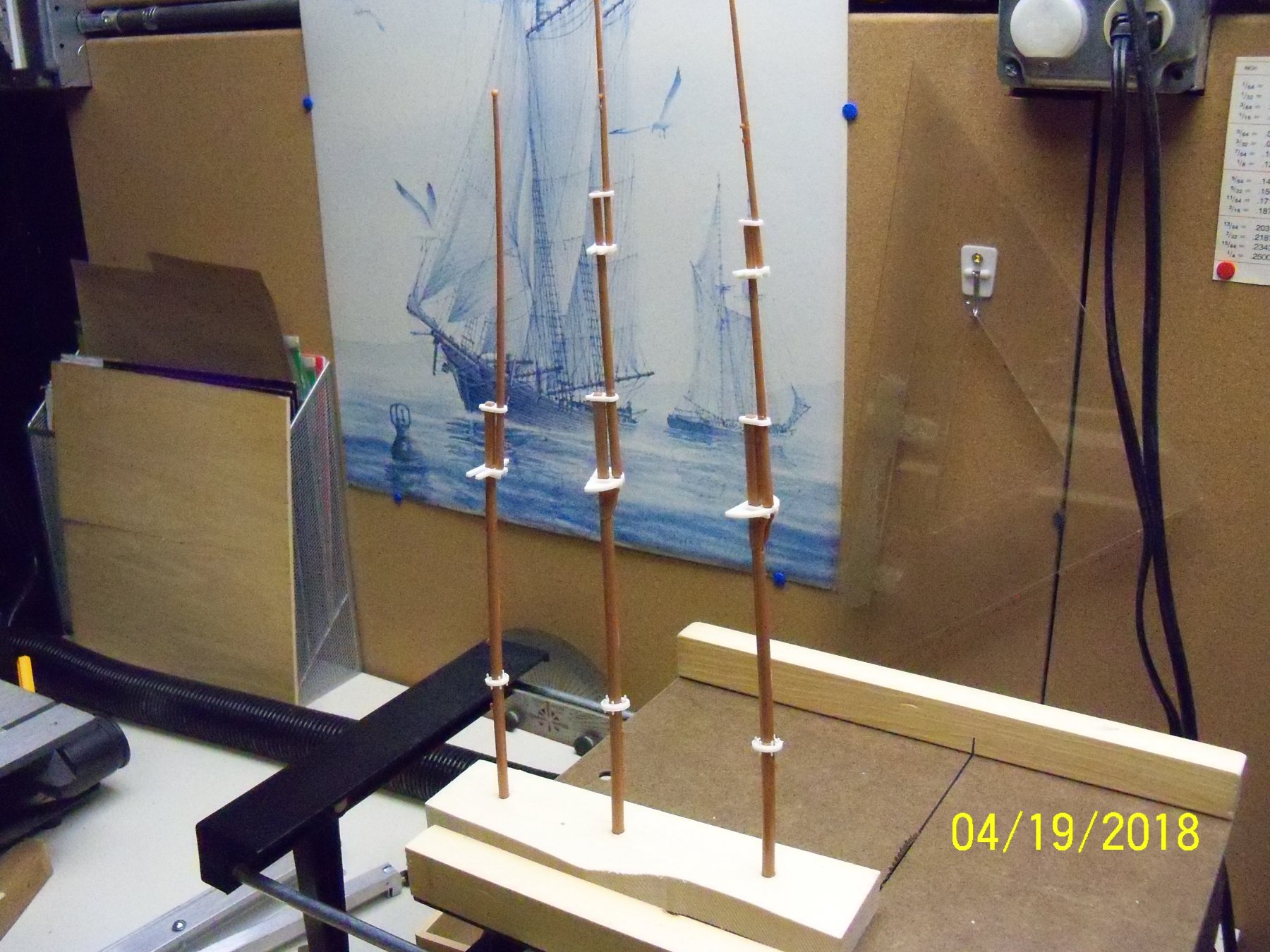
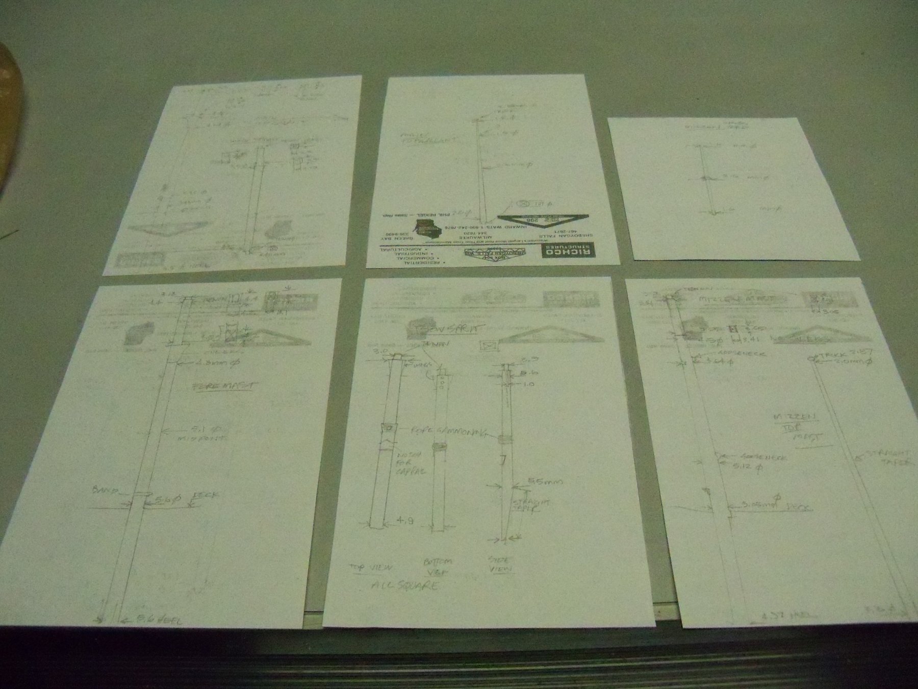
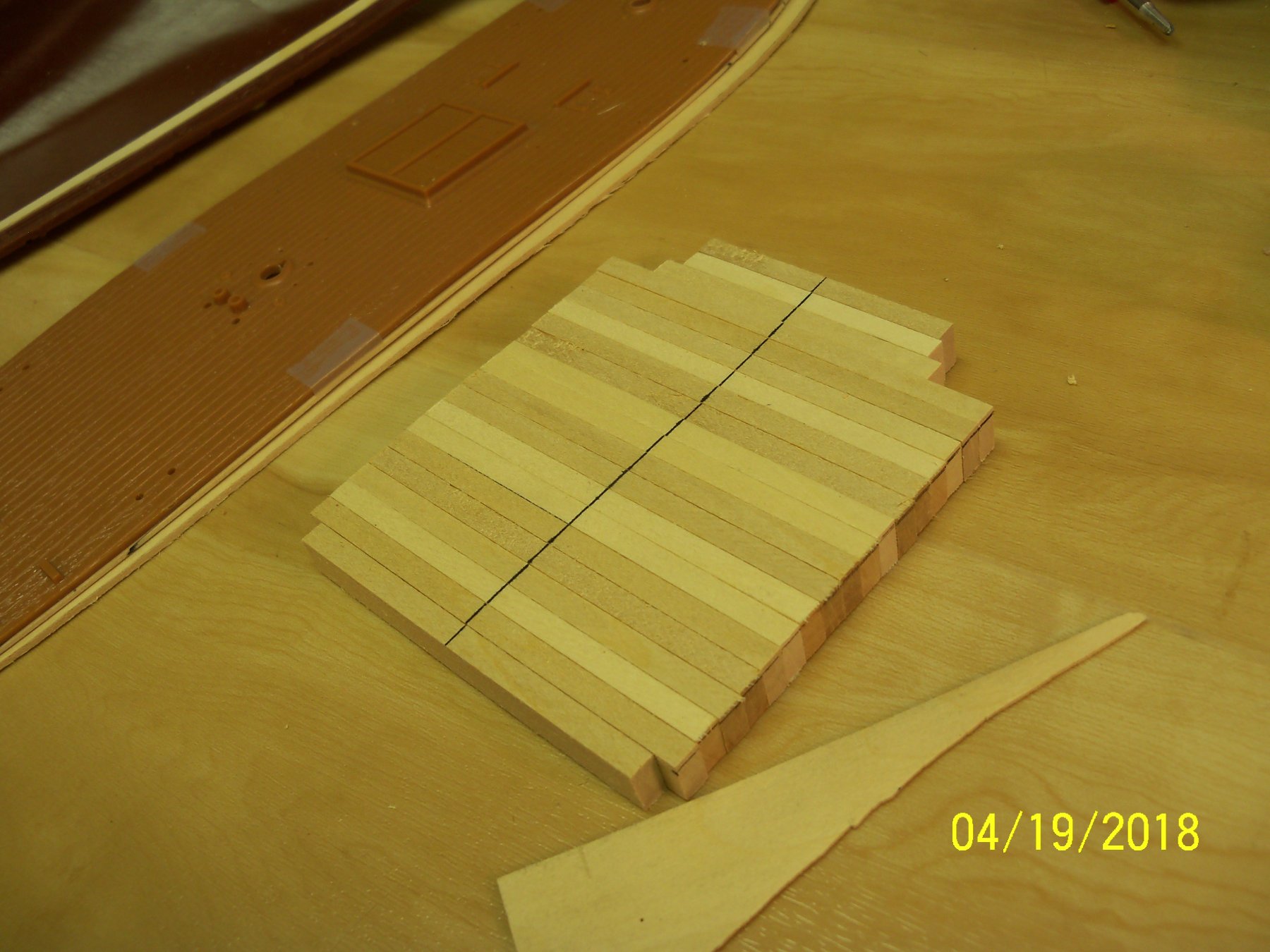
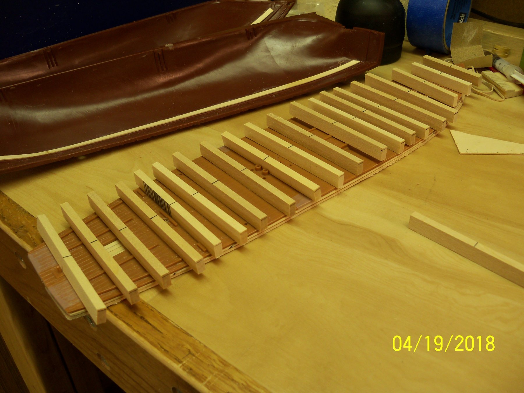
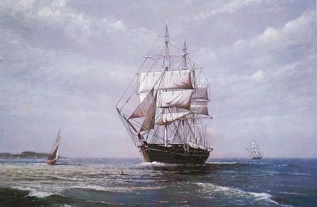
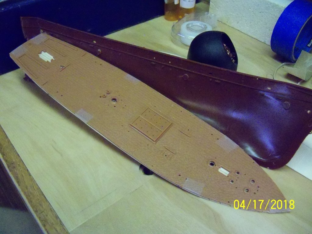
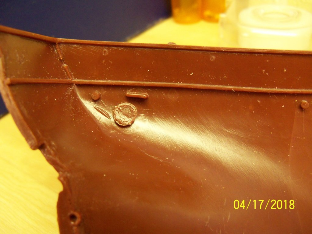
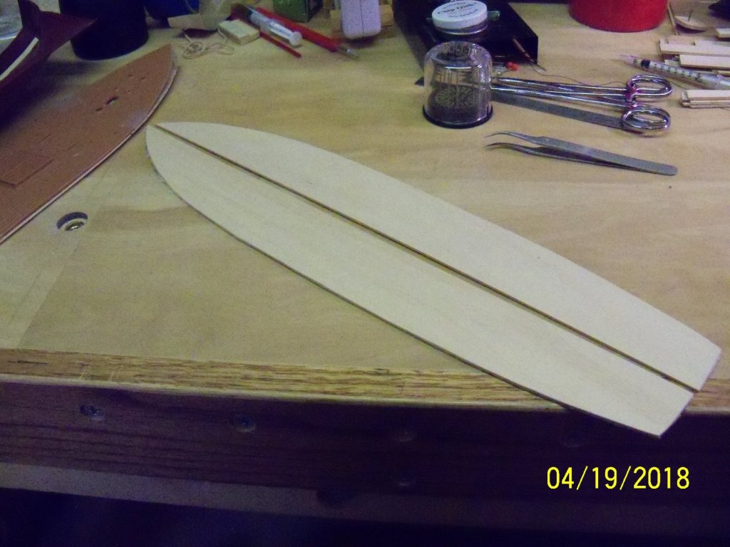
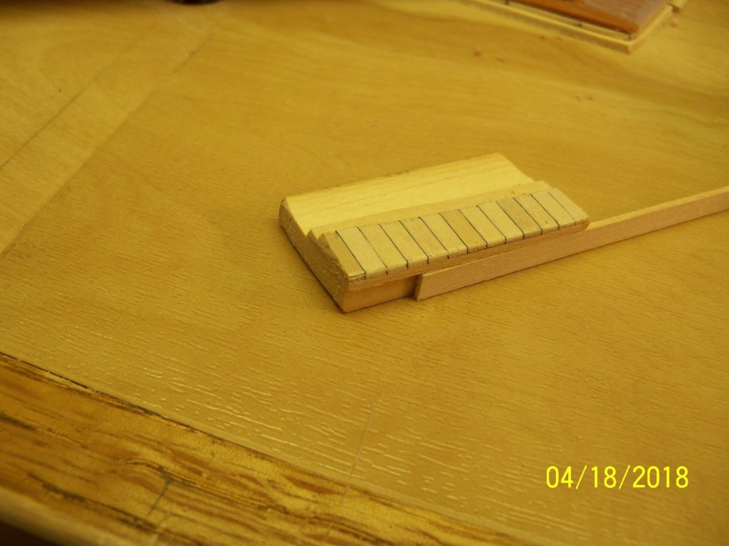
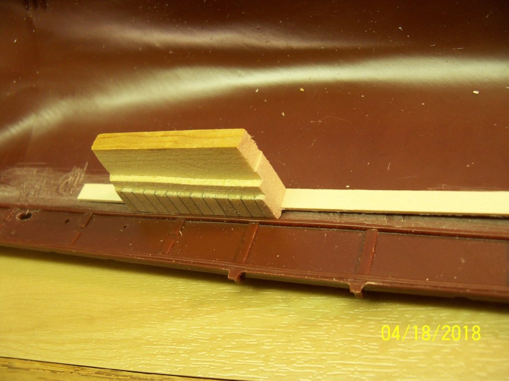
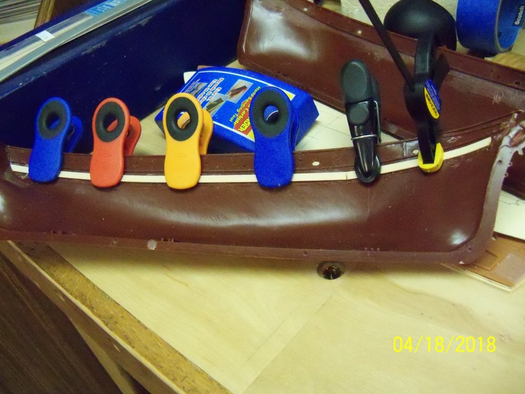
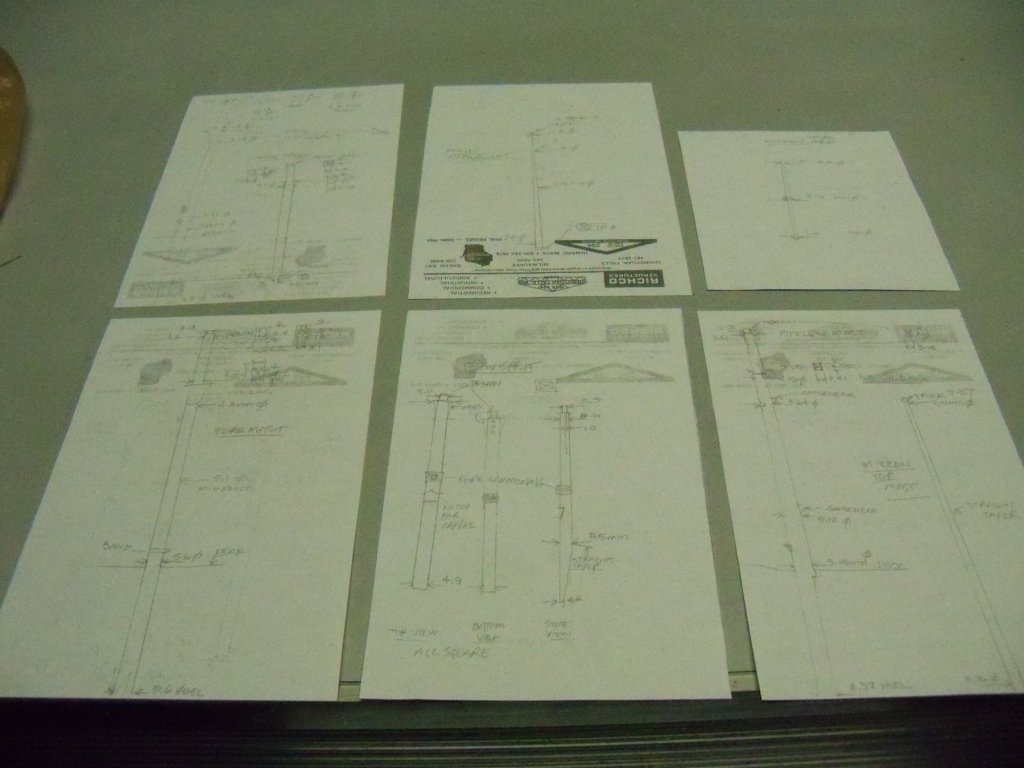
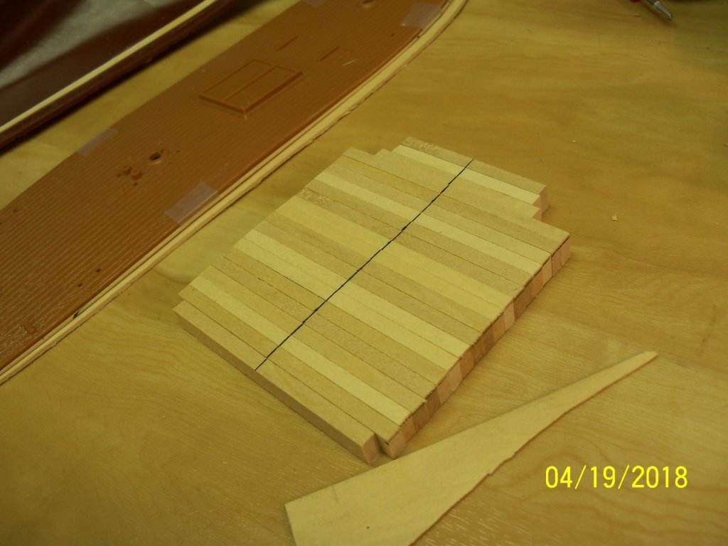
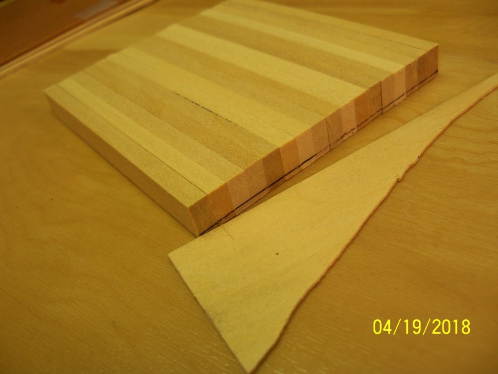
 This model was just sitting on a shelf patiently waiting for some attention when a friend of mine saw it and wondered if I could build it for his office. While I am currently working on the MS Phantom, I thought I could do both and try my hand at making a build log for this one. I suspect that this method of model building is quite unusual, To tell the truth, I was not certain that this belonged in the kit built category, as the only part of the kit that is being used is the hull with all the rest being scratch built from wood and metal. My friend was actually interested in a wooden ship, but I told him that I could replace most of the plastic parts with wood. I told him I’ve done that before and he agreed that it would probably look better that way, as the kit had heavy plastic sails moulded right to the spars and the deck had a lot of the details moulded right on which he thought looked pretty bad. As I reopened the box to examine the kit I found that the instruction manual was missing! Luckily, I had built this ship before in wood and still had the blueprints from A.J. Fisher. The plastic deck was not very impressive with a lot of the details moulded on it, but it was a one piece deck so that would make it easier to use as a template to make a wood replacement. Before I actually started construction, I decided that I wanted to do a search in the internet for more details of the actual ship. One thing that really caught my attention right off the bat, was the fact that the real ship only had four sails on the main and foremasts and not five as shown both in the kit and my set of blueprints. These two pictures below show both the box art and one of the pictures that I found showing the ship as it was built. Discovering this, I decided to really do some digging to see if any other discrepancies were evident. There were a few, but nothing as glaring as the sails. Taking the plastic deck in hand, I traced the outline onto a piece of manila folder including the mast holes, marked the center line of the deck, and transferred the outline of the hatch as shown below. As the end of the hull was closed in and the tumble home of the hull sides was too severe to allow a one piece deck to be slipped into place, I decided that I would have to split the deck down the middle for it to be installed. I took two 3”x24” sheets of glued up 1/8” wide 1/32” thick decking boards that were glued up with black colored glue to represent the caulking joints and joined them together edge to edge with tape across the backside. Placing the manila pattern over the pair of decking sheets, I taped them together, being careful to align the center-lines of the pattern and the joint of the two decking sheets. I traced this outline onto the decking sheets and unassembled it to allow easier cutting of the rough outline of the two deck pieces on my scroll saw. After cutting, the next step was to carefully tape the rough cut decking sheets back together again on their backside and tape these under the original plastic deck. Once again, I was careful to align that center joint of the decking with the center of the plastic deck. This assembly was then taken to my belt sander and sanded close to the edge. I would sand up to the tape and re-position the tape as I went along. (This was necessary because the plastic deck was quite warped and once untapped; it wanted to spring away from the decking sheets.) At this point the assembly was taken to my drill press. I drilled all of the larger round holes right thru the plastic deck to assure that they would align exactly. (This was especially important for the heel of the masts to align with the mast steps on the inside of the hull.) I then took the whole assembly to my workbench and drilled all of the remaining round holes with matching small bits in a pin vice. Here is a picture below of my progress to this point. Taking a look here at the inside surface of the hull, you can see that the waterway was already moulded on and would remain. However, the projecting tabs for support of the plastic deck and the injection mold stubs would have to be removed. Taking my new battery powered Dremel, I ground off all of these unwanted projections and sanded them smooth to allow me to glue some 1/32”x 13/64” basswood strips to serve as a ledger to support some new deck support beams. I decided that I should make a 1/16” thick basswood sub-deck, as the decking sheet was very thin, so I cut up two sheets of basswood for the sub-deck similar to the decking sheet as shown here. (notice the plastic decking springing away from the tapped wood deck) Then I made up a spacing jig to help align the top edge of the planking to the underside of the moulded waterway. Taking short pieces of the decking and sub-deck for spacers, I glued them to a thicker piece of wood for a handle as shown. Here is a picture of the spacer jig in use. Using this spacer jig as a guide, I used some thin ACC to attach the 1/32”x 13/64” basswood for the beam support ledger and clamped it in place for it to totally set up overnight. While the hull was drying I decided to work on the upper structure. The first thing I did with the masts and bowsprit was to do a trial assembly without glue of all the components to see how they all fit together. Disassembling these assemblies, I drew up some dimensioned diagrams of all the components for making their wooden replacements. The lengths were all drawn full size and the widths were written out next to their locations. Returning to the hull construction, I cut 17 3 ½” long pieces and 4 shorter pieces of 3/8”x 3/16” basswood to use for the deck beams. The kit was designed (as most plastic models are) to have a flat deck, so I worked up a method of adding the camber to it. I marked the center-line of all of the beams on their top edge as shown below. The camber was scaled off the 1/6” scale A.J. Fisher blueprints and converted to the models 1:87 scale. This worked out to about a 1/16” slope. Flipping over the whole stack of full length beams, I shifted the full size beams up against a piece of 1/32” scrap wood (to account for the approximate 1/32” width of the pen point), and marked all of the pieces on both ends. I set the beams on top of the plastic deck to get an idea of how to arrange them. That’s as far as I’ve gotten so far, I will post more later on the shaping and installation of the beams.
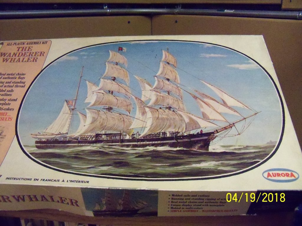


- 107 replies
-
- 15
-

-
 I had started some build log in the former edition of this forum, and for a number of reasons I did not rewrite it in the new version. Some of the reasons (excuses): - A lot of work involved - Not familiar with the new procedures to insert pics - Long term inactivity on the project - Moderate interest from other members… I have now restarted the build and will re-post some of the previously sent pictures, if I manage to tackle the pictures insertion. Anyway this is the model as it looks now. Any critical or better, constructive meaning is more than welcome, bearing in mind that not a lot can be changed to what is already done. Question. I want to give the ship a name. For a number of reasons I will explain later, this will be “The Pole Star” or rather in Dutch “De Poolster”. Problem is that Dutch spelling of the 17th century is not something I am familiar with, so the name could also have been written Poolsterre or stern or sterne. Any idea from the Dutch colleagues?
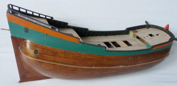
-
 Hello fellow MSW members After finishing my Cross section build I wasn't sure what my next project would be . While looking at different boats i started thinking back to when I was young .I was born in New Bedford Massachusetts,and as a kid I can remember visiting the Whaling Mueseum . https://www.whalingmuseum.org/ and they always had such great stuff on display and in the Bourne building was a massive display of the vessel "Lagoda" . As a kid I couldn't wait to get to the vessel to explore it .My grandmother lived maybe a mile away from the museum so we would go visit several times a year. I contacted a member from the museum and she was very helpful in sending me the information on the Lagoda,and how to purchase the plans for the vessel. So without hesitation i called and purchased them as they only had the one set left . Now I will impatiently wait for them to arrive. Here is a link to the " Lagoda "if you would like to check her out . https://www.whalingmuseum.org/explore/exhibitions/current/lagoda Thanks for checking in on my new adventure. Derek C.
 -
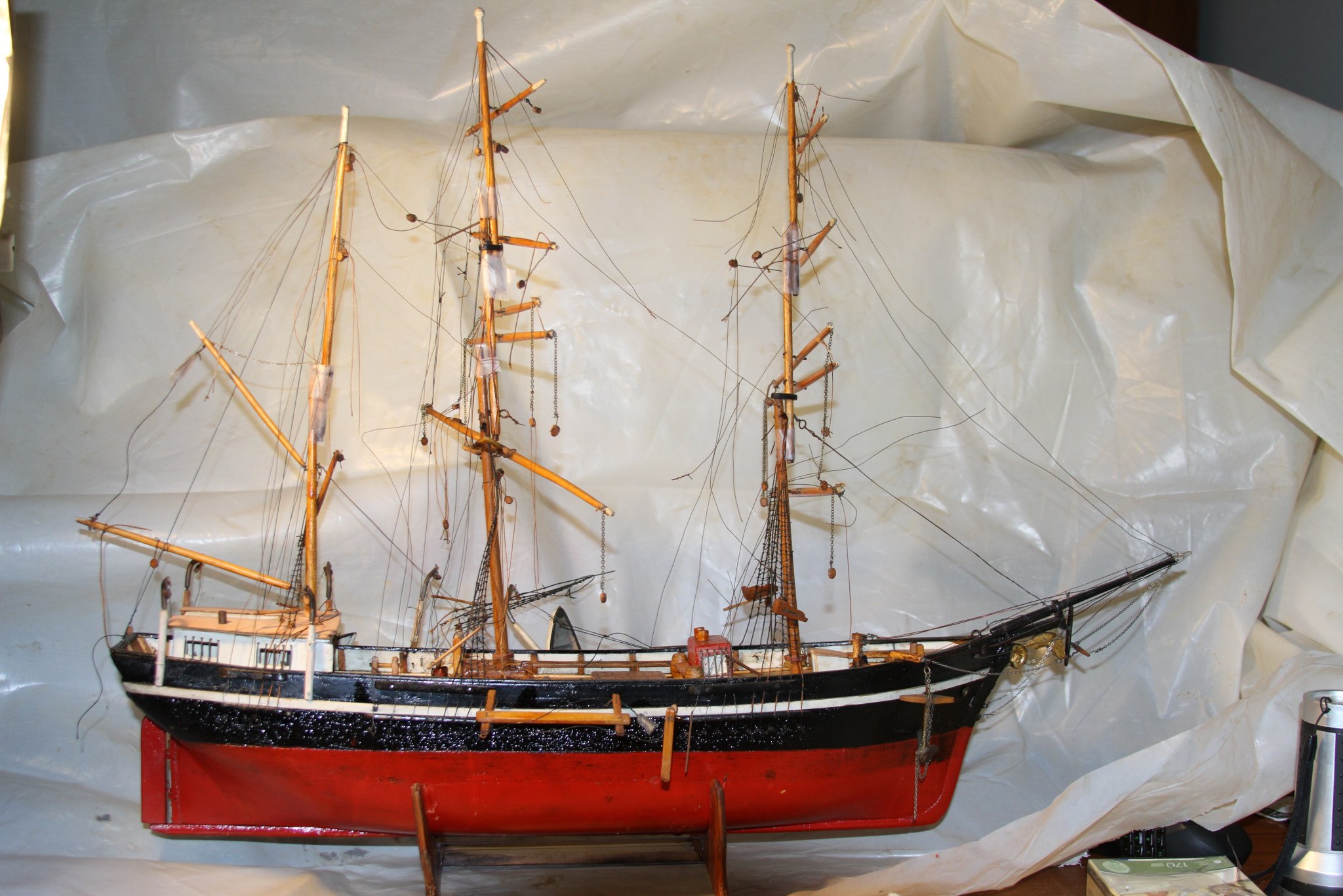
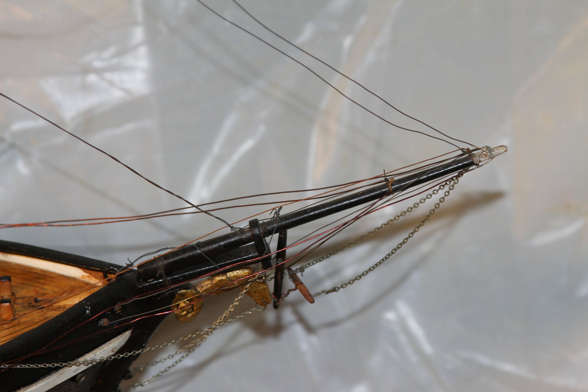
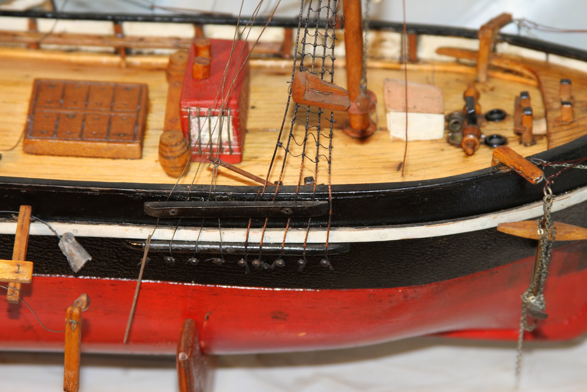
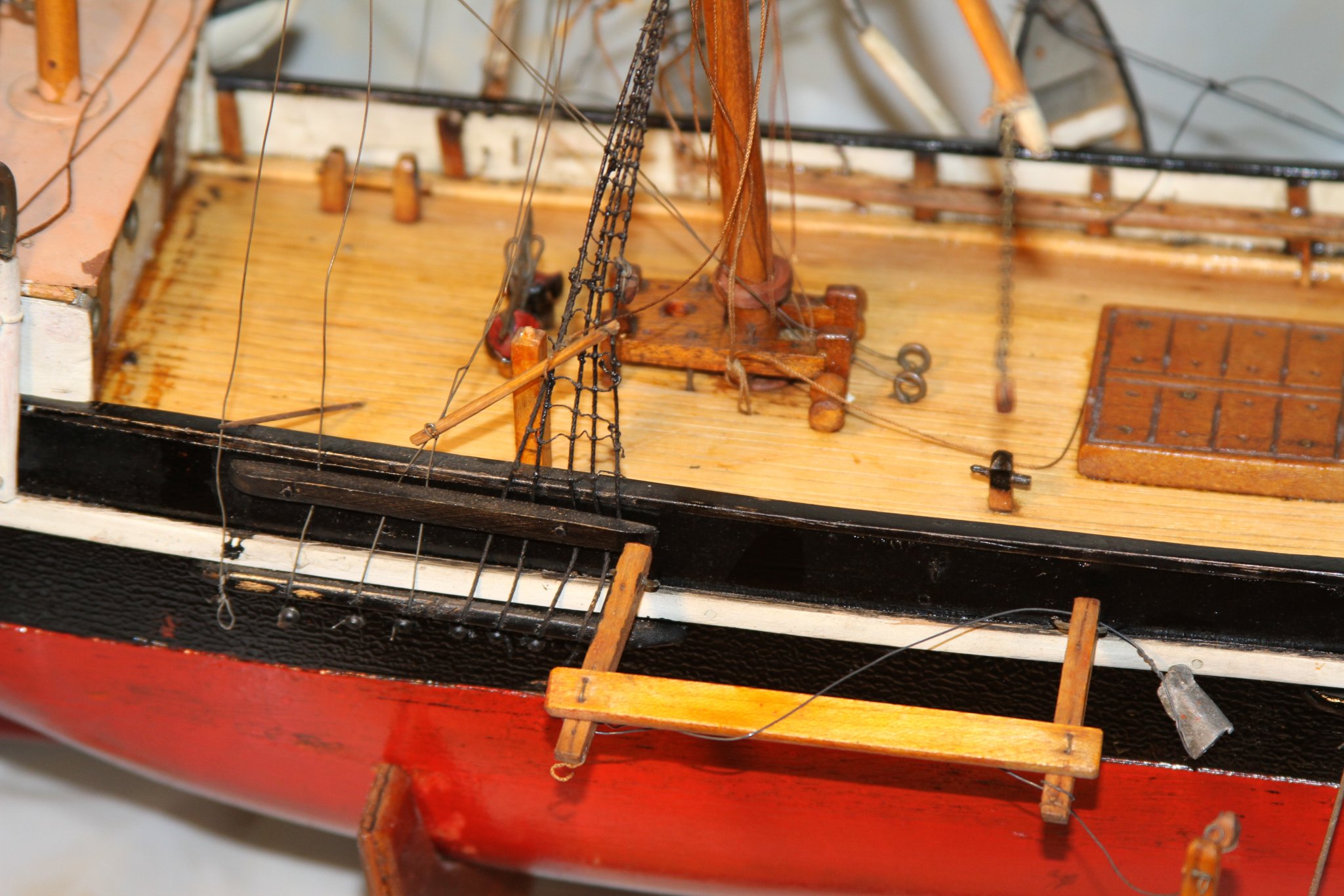
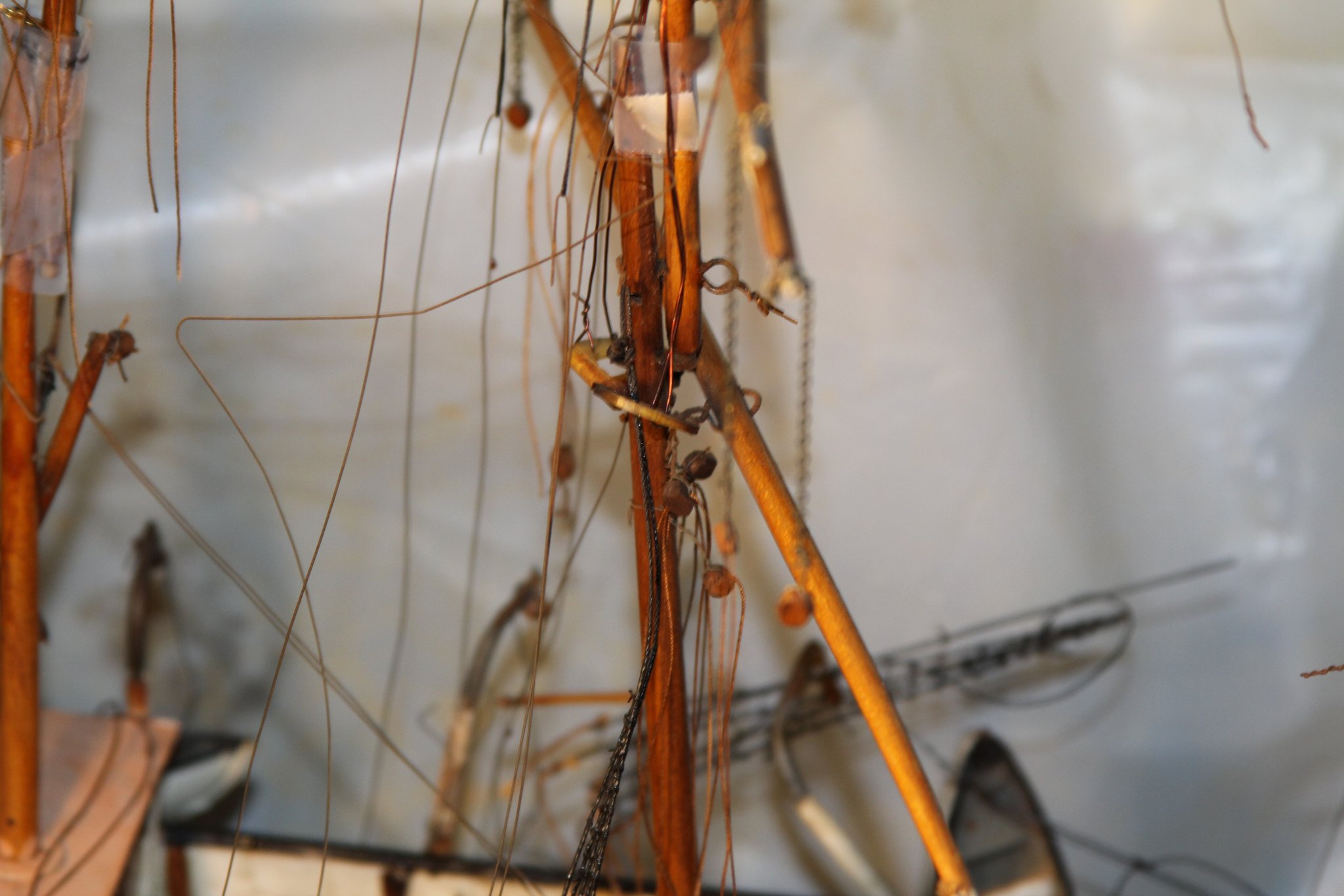
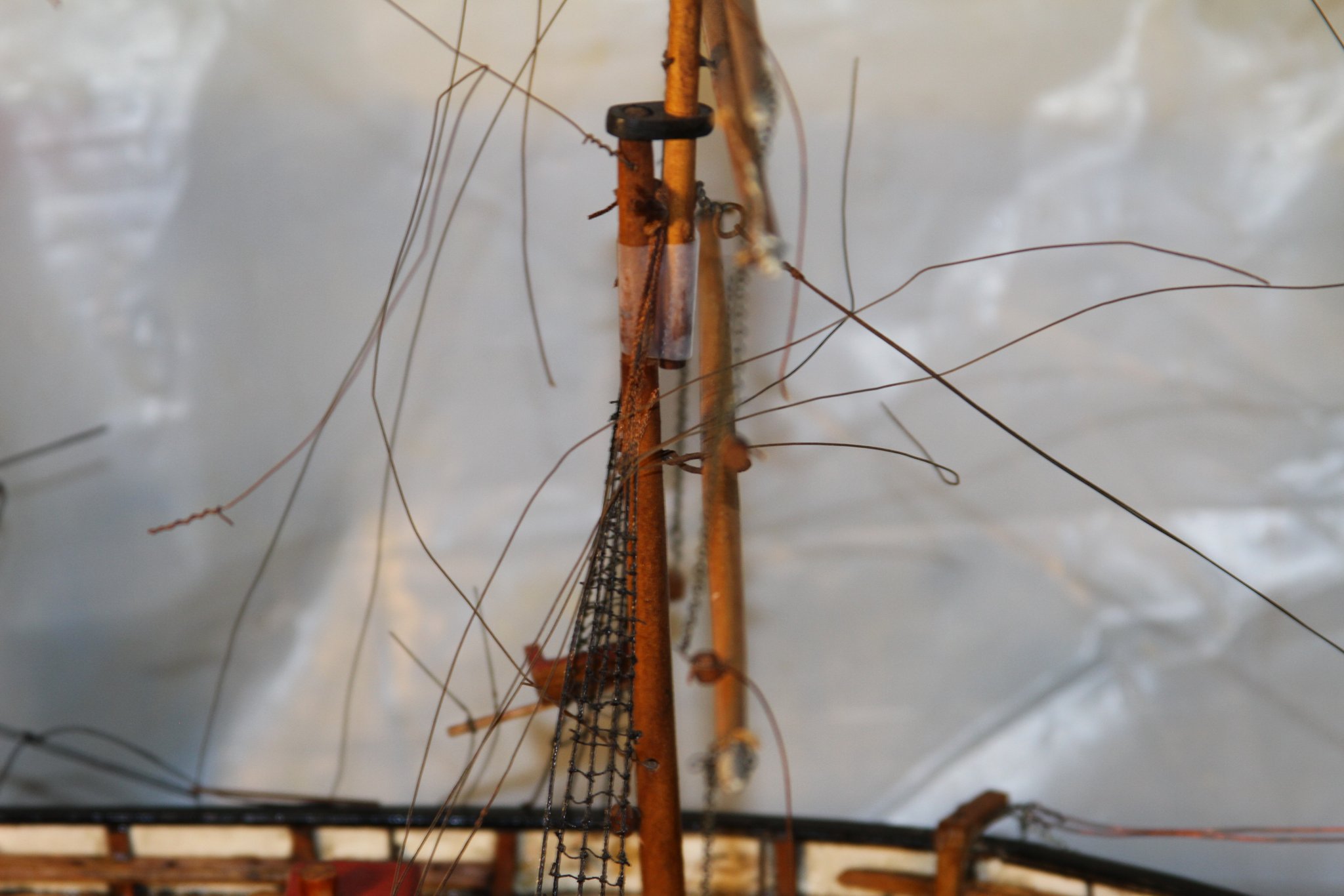
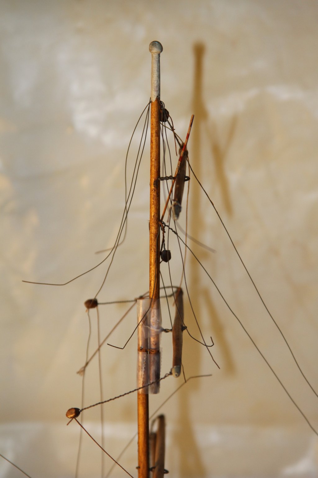
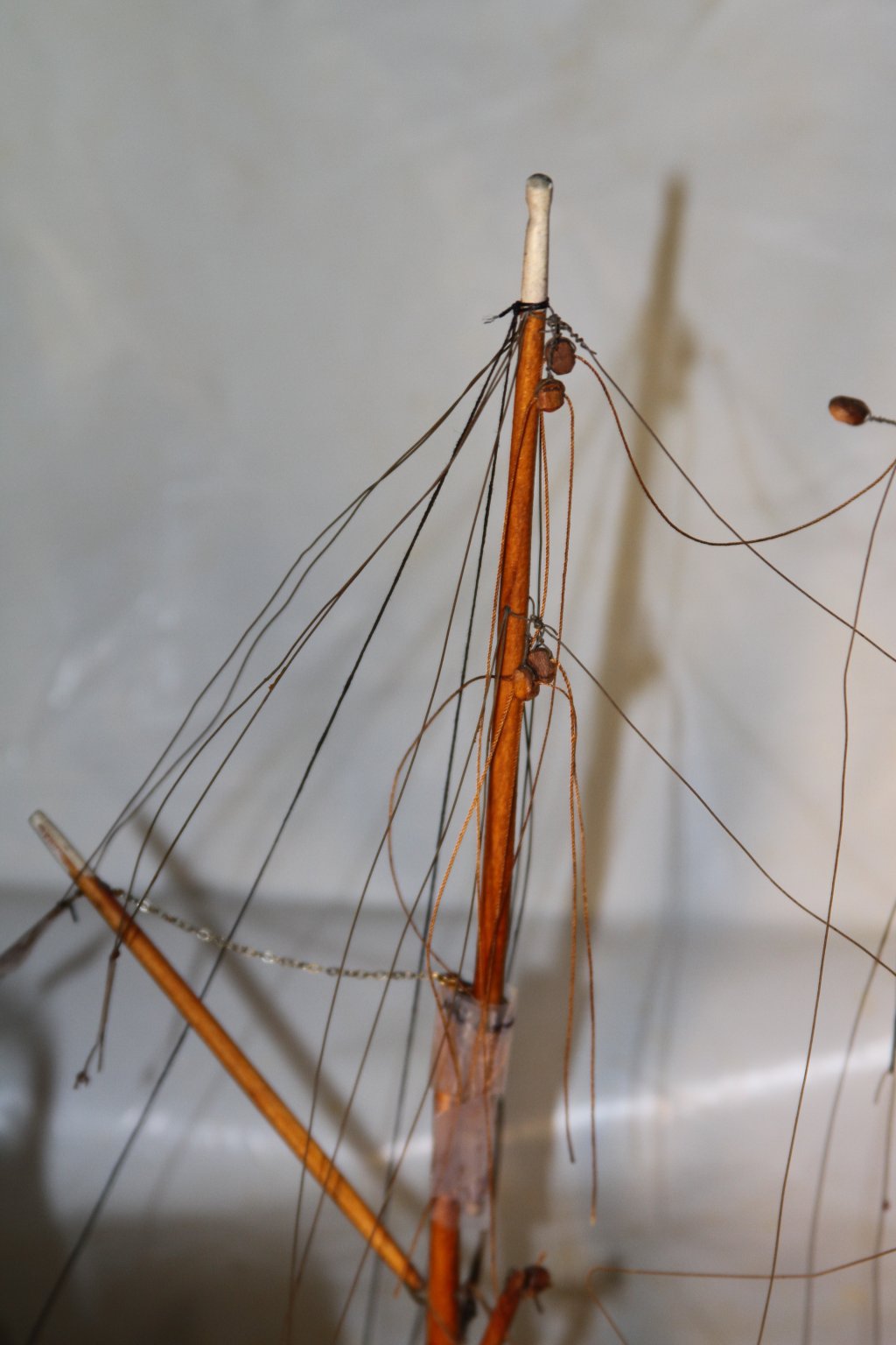
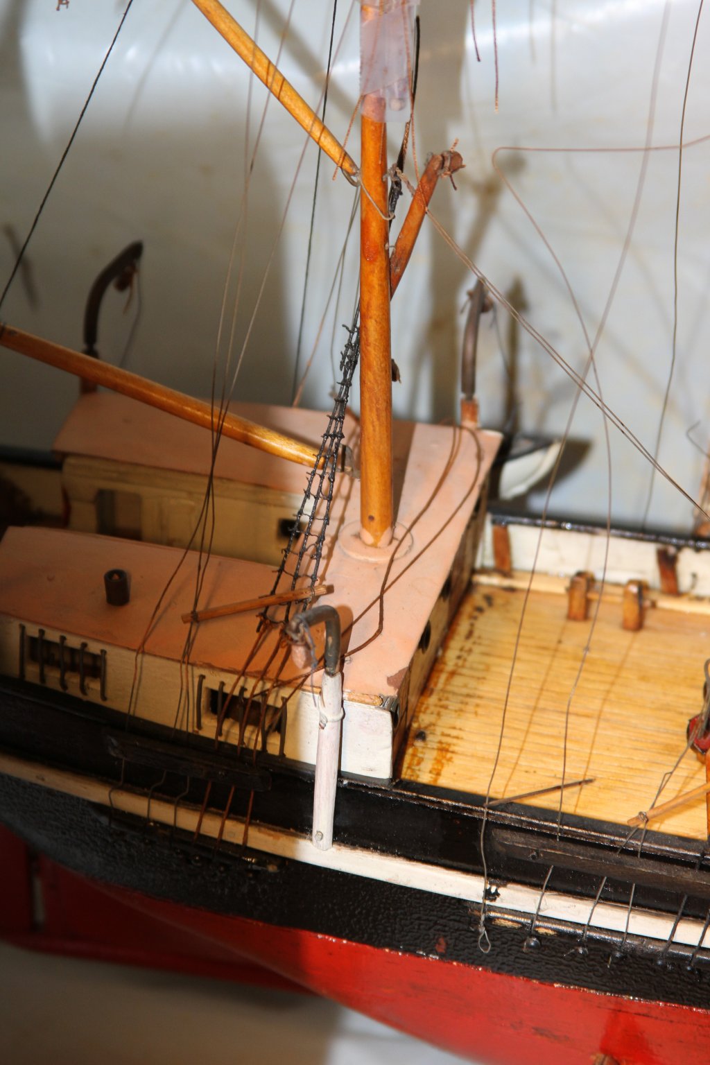
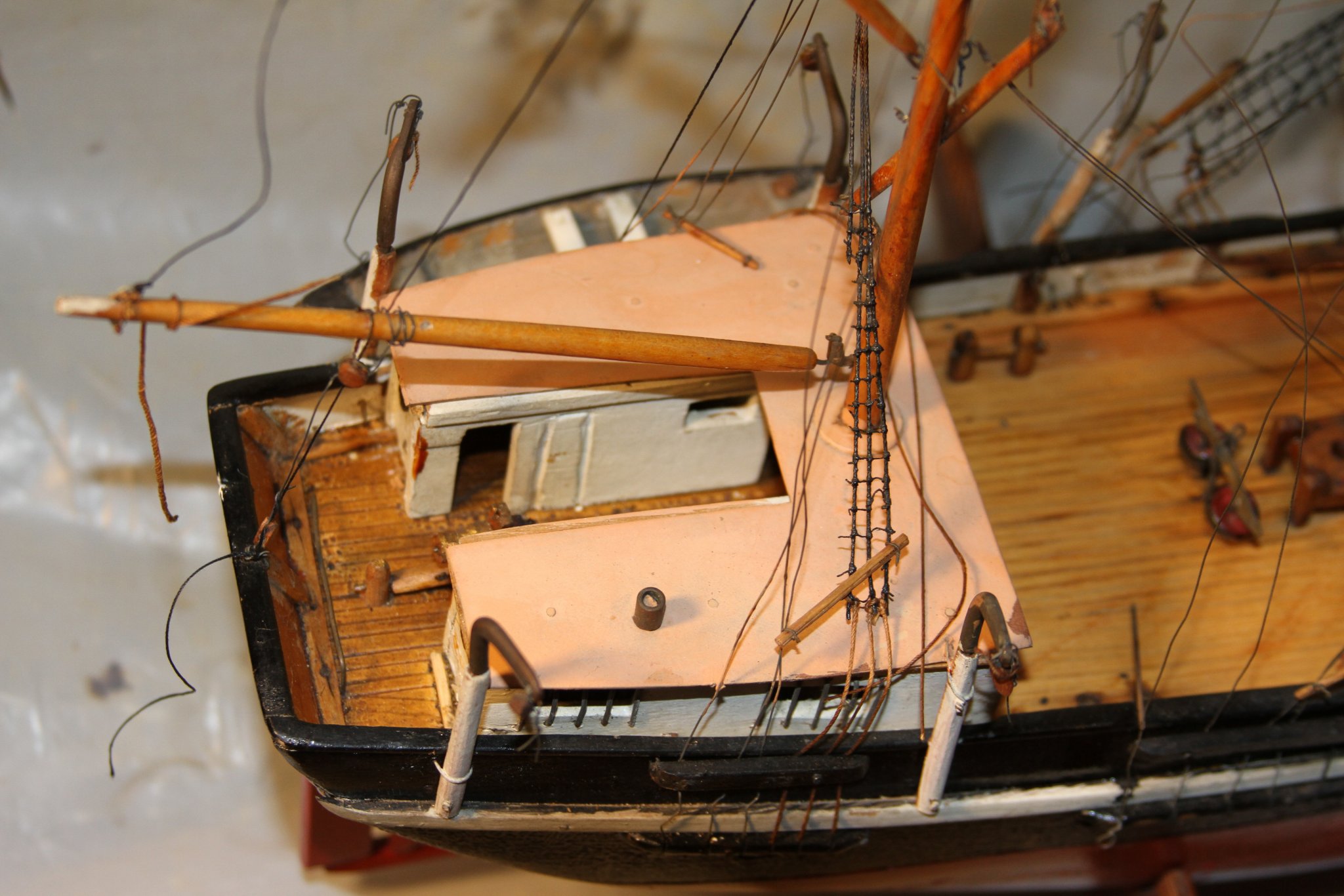
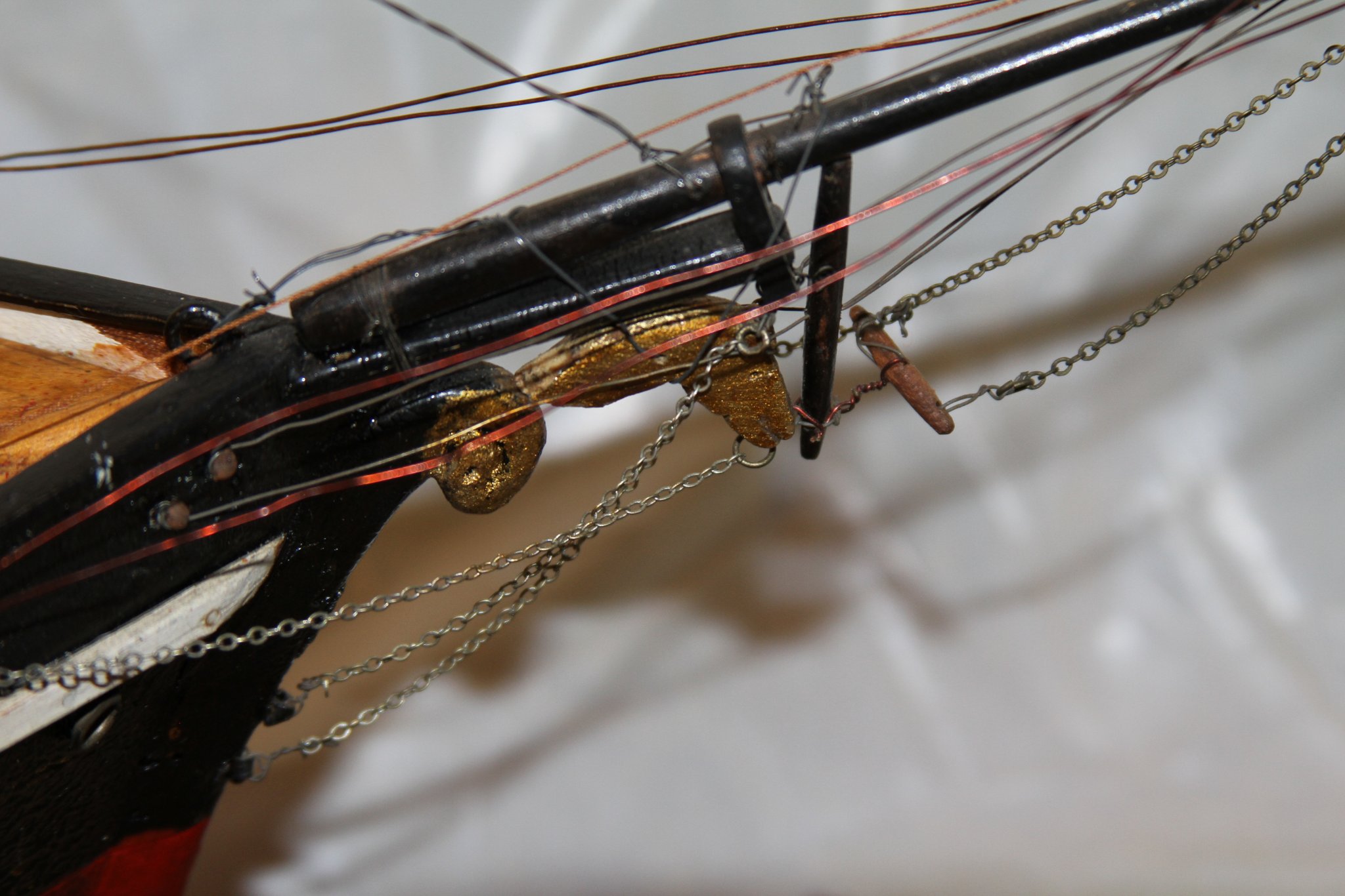
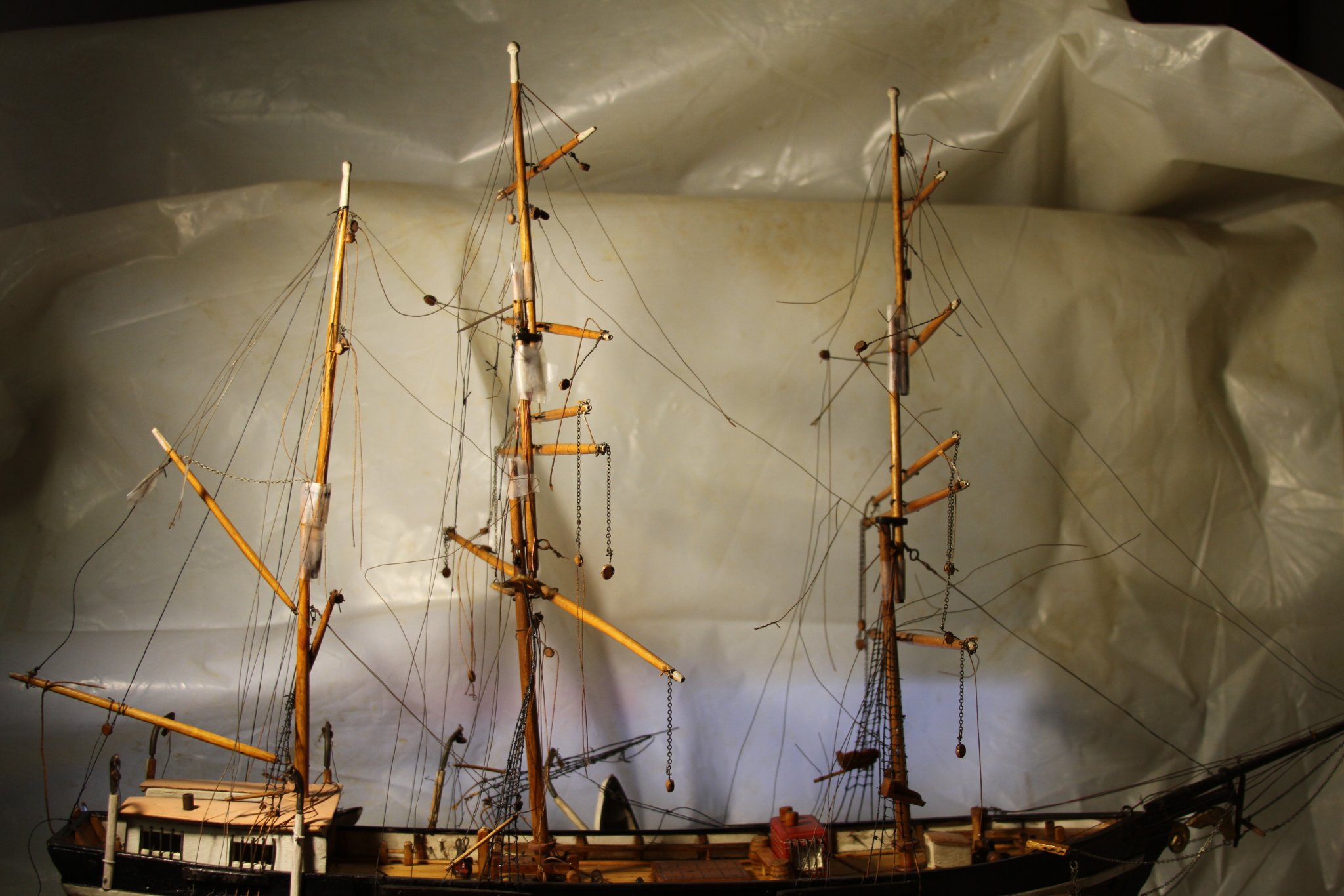
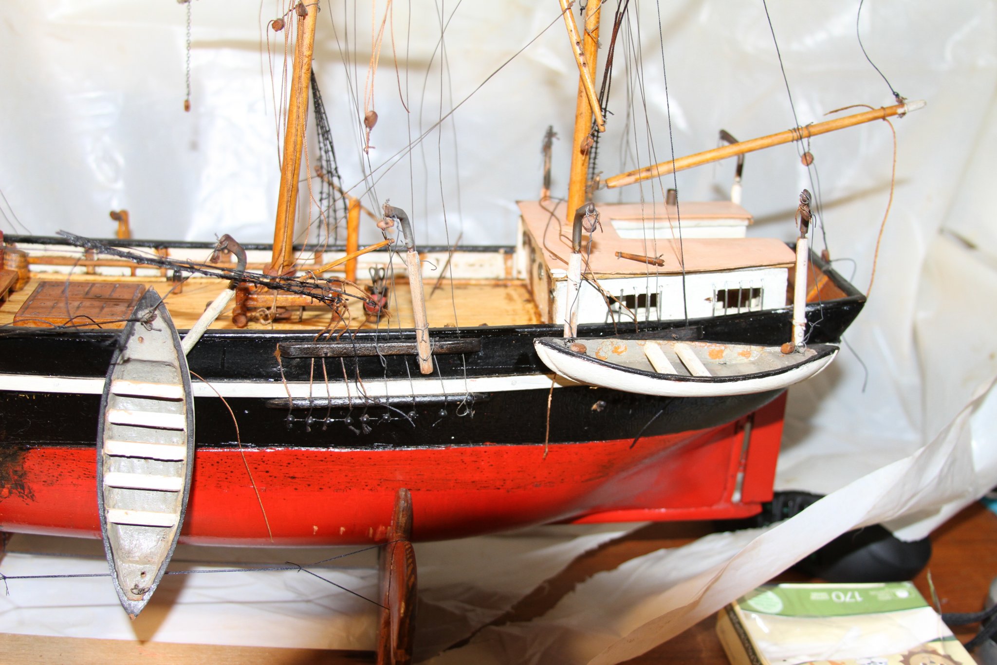
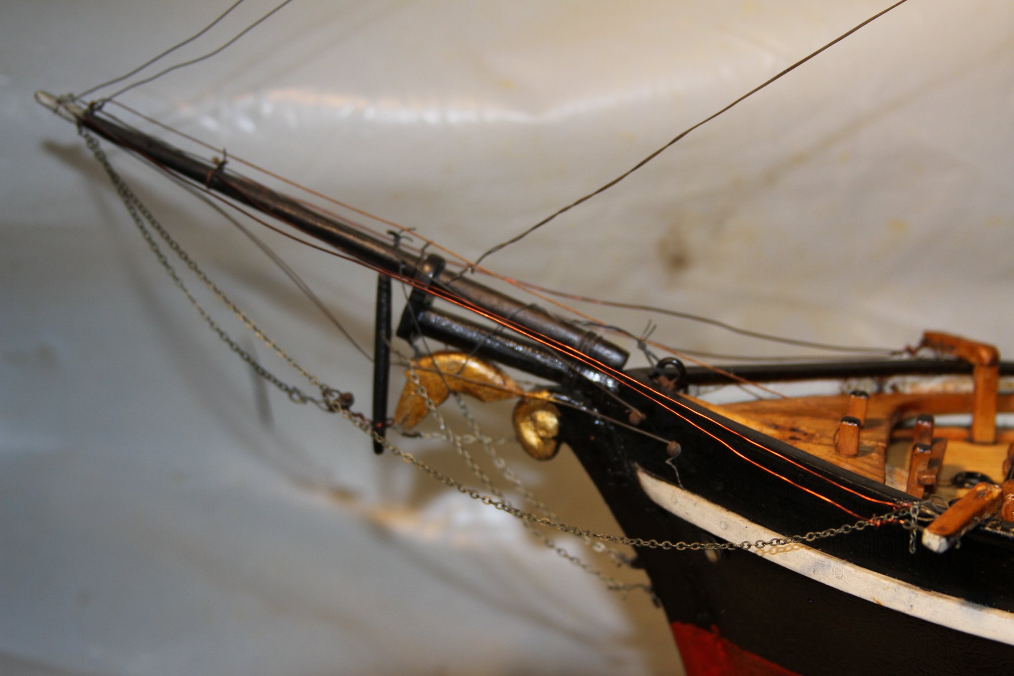
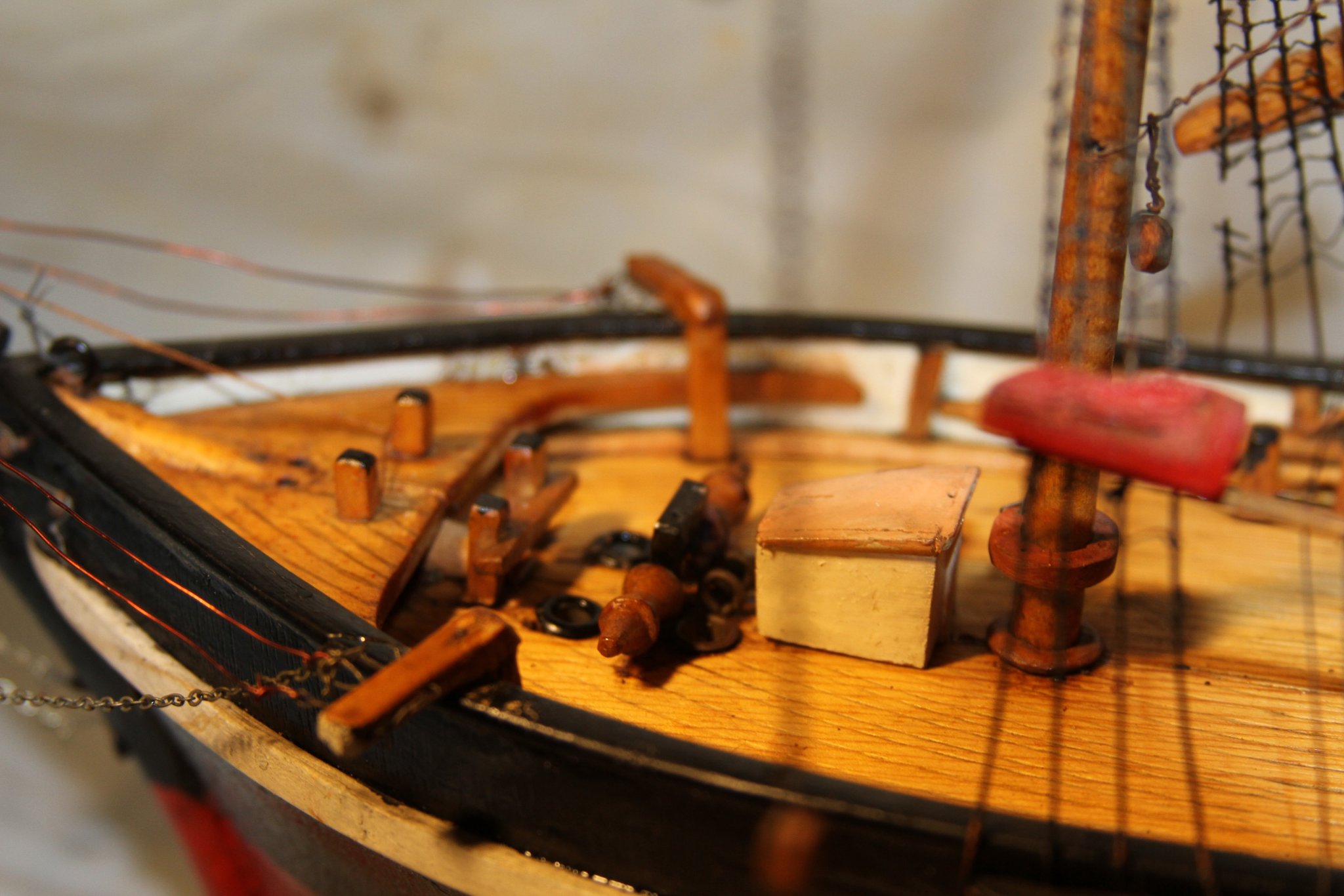
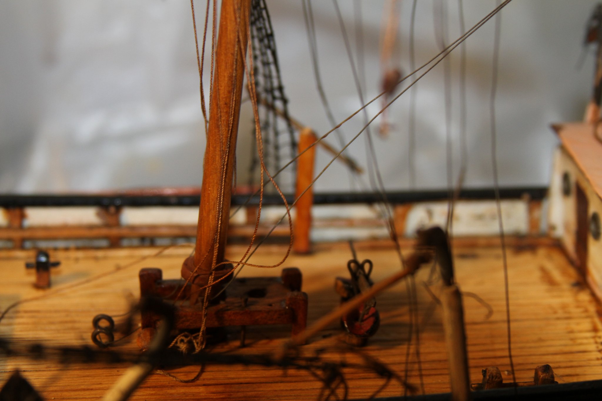
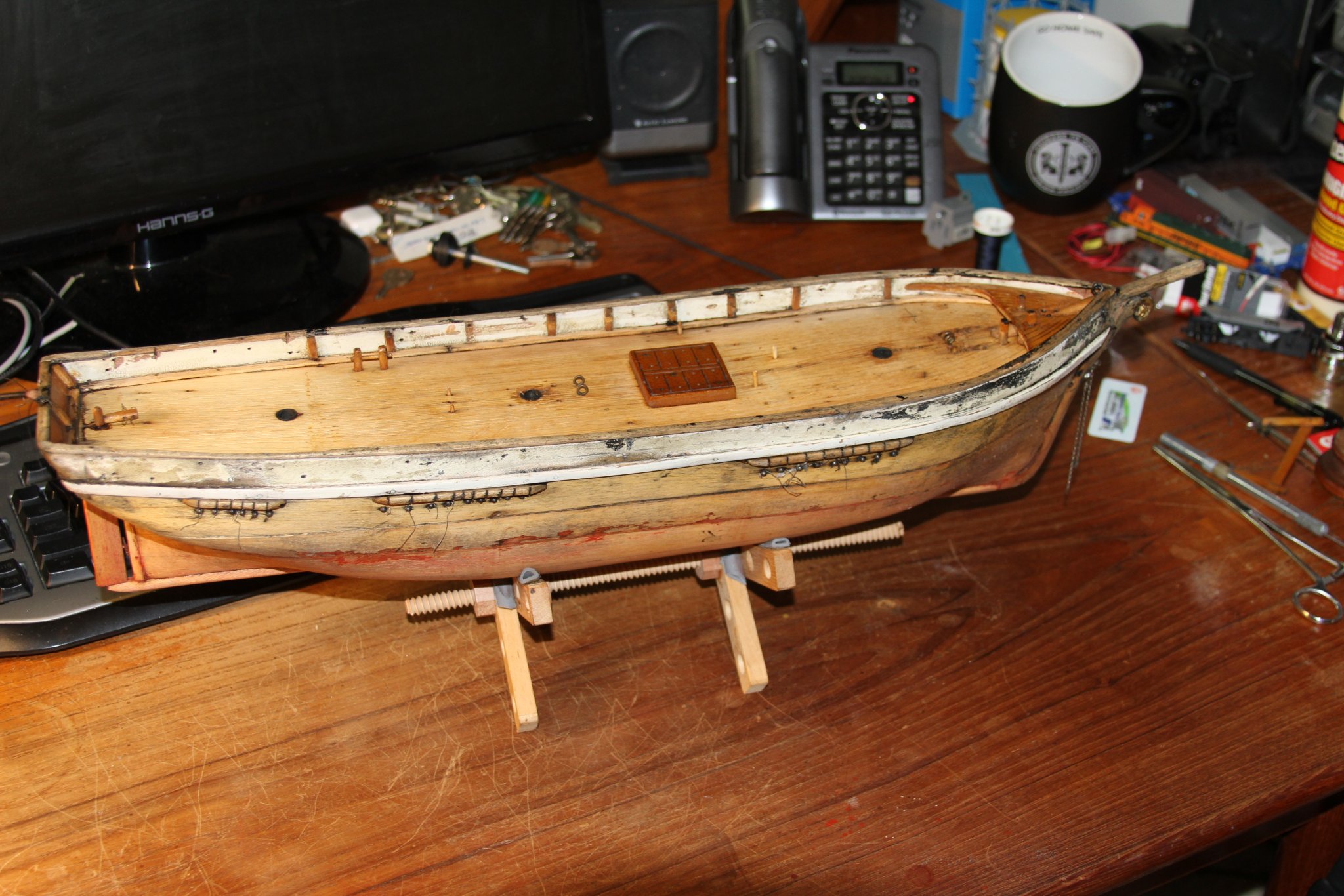
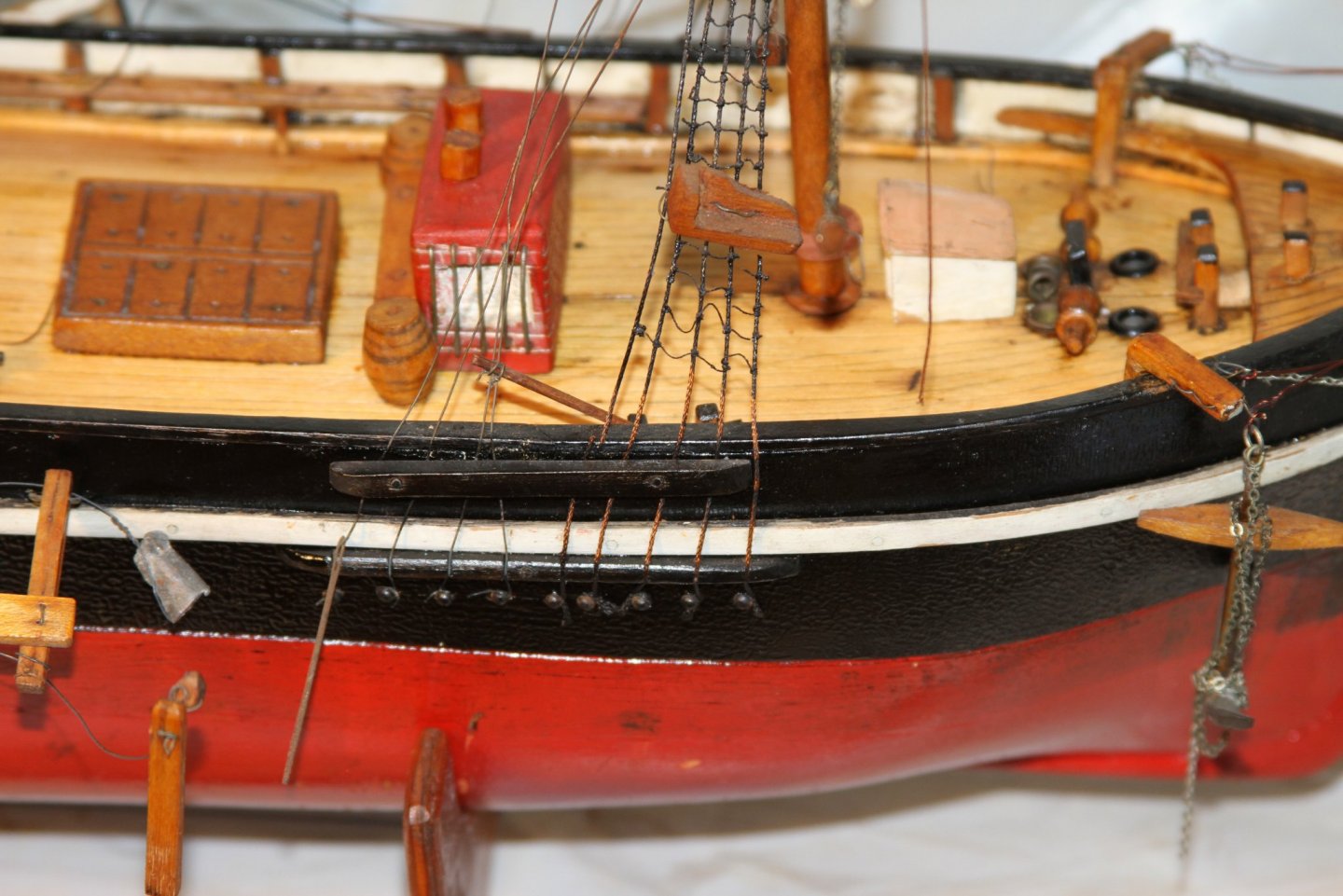
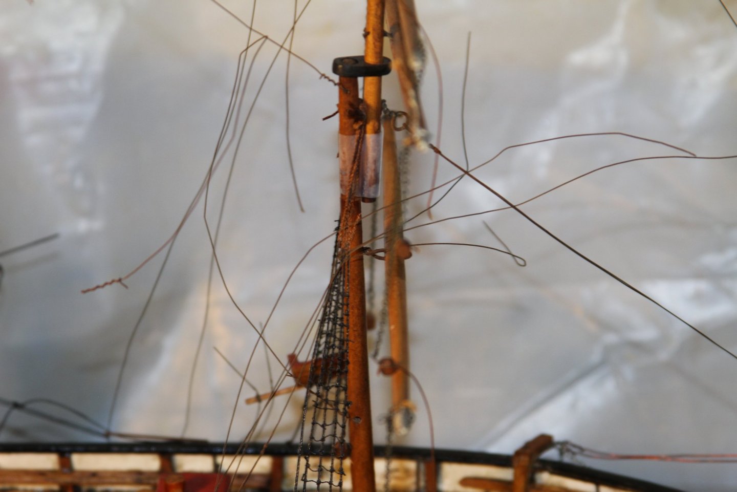
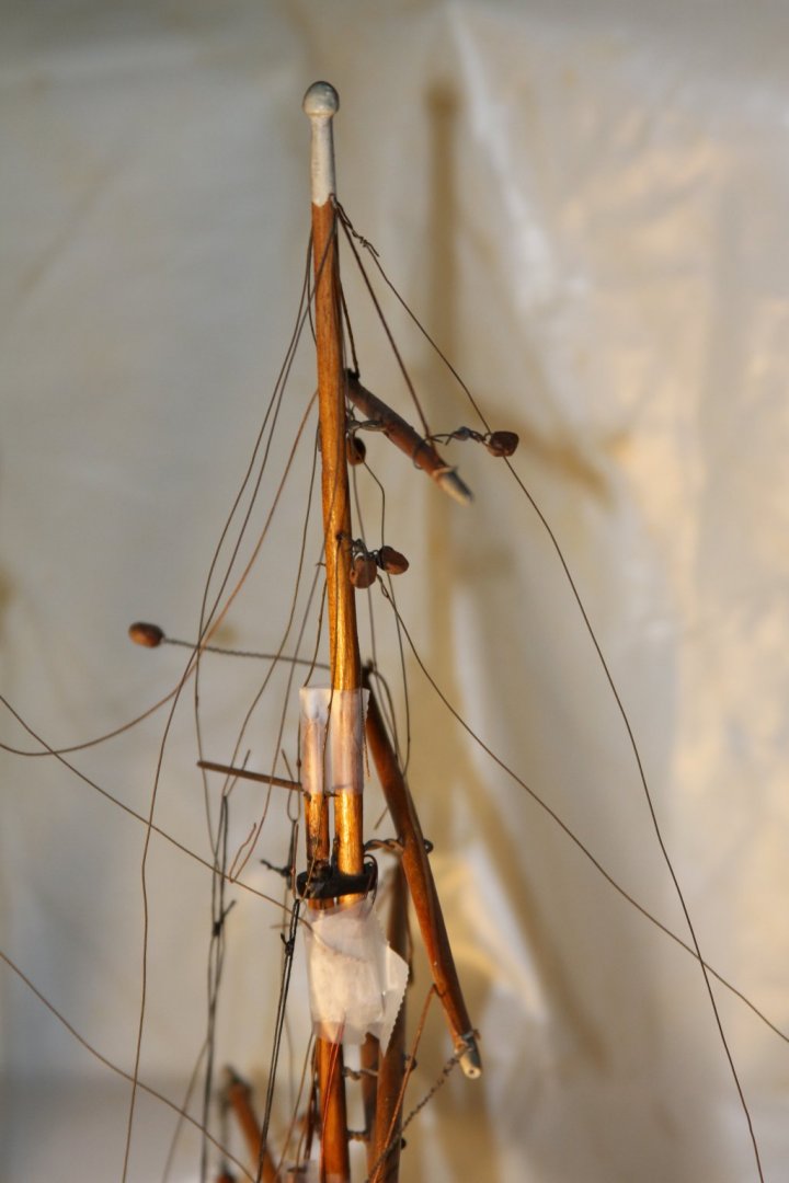
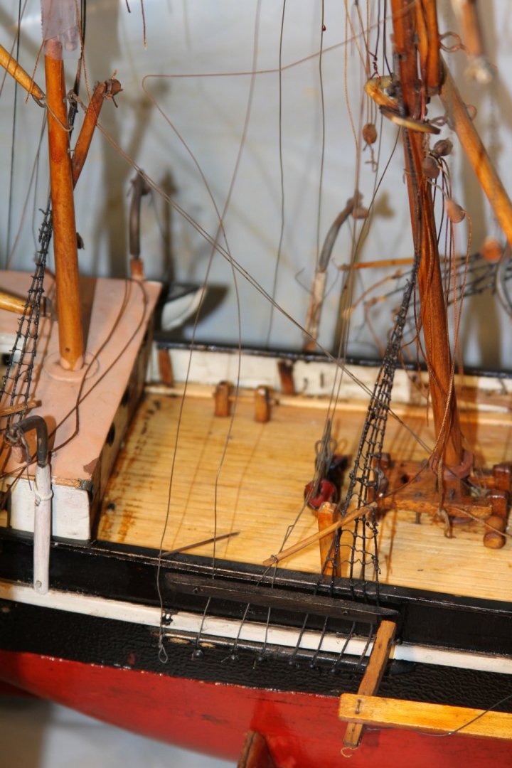
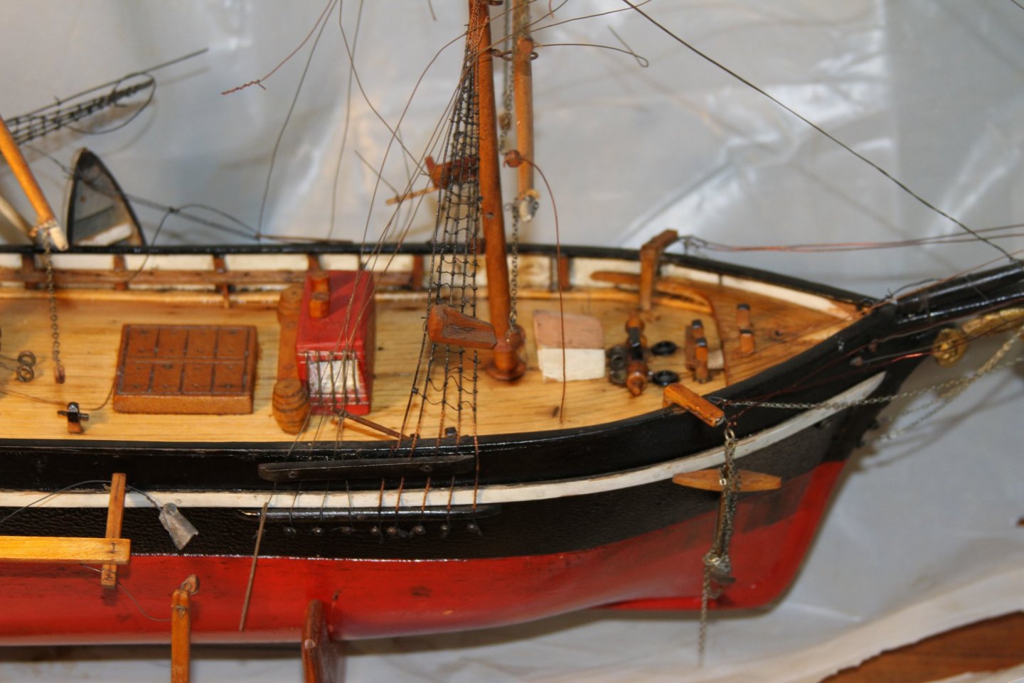
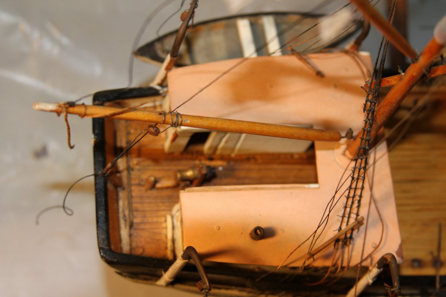
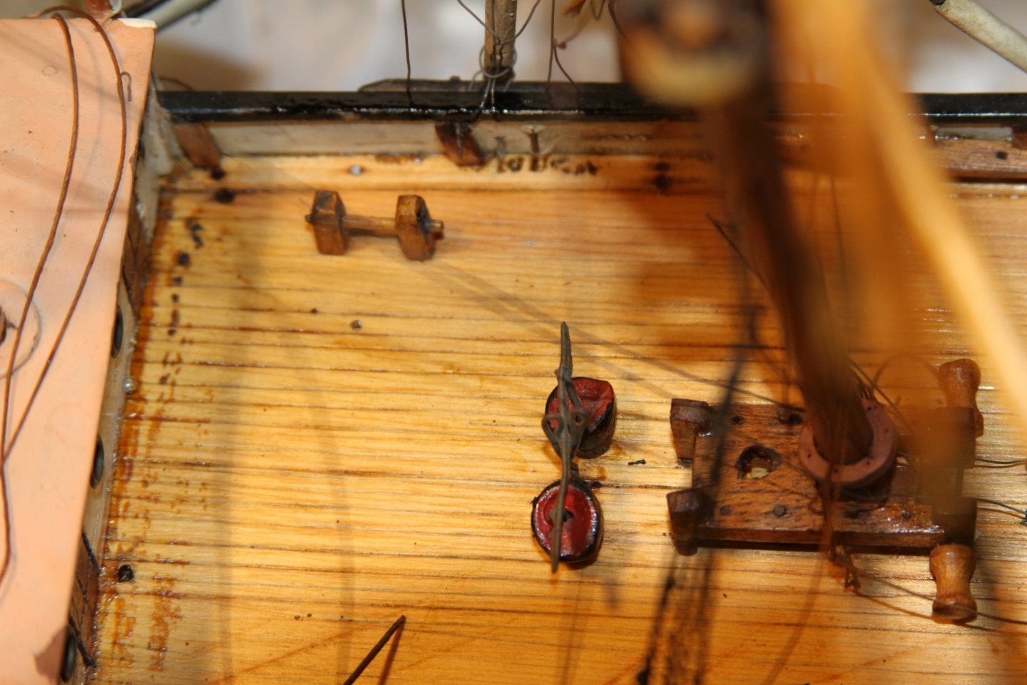
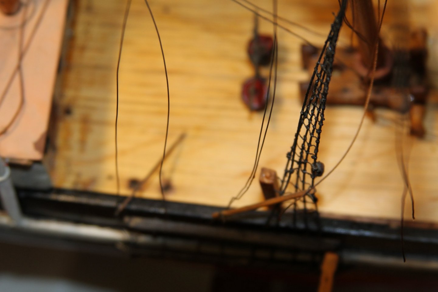
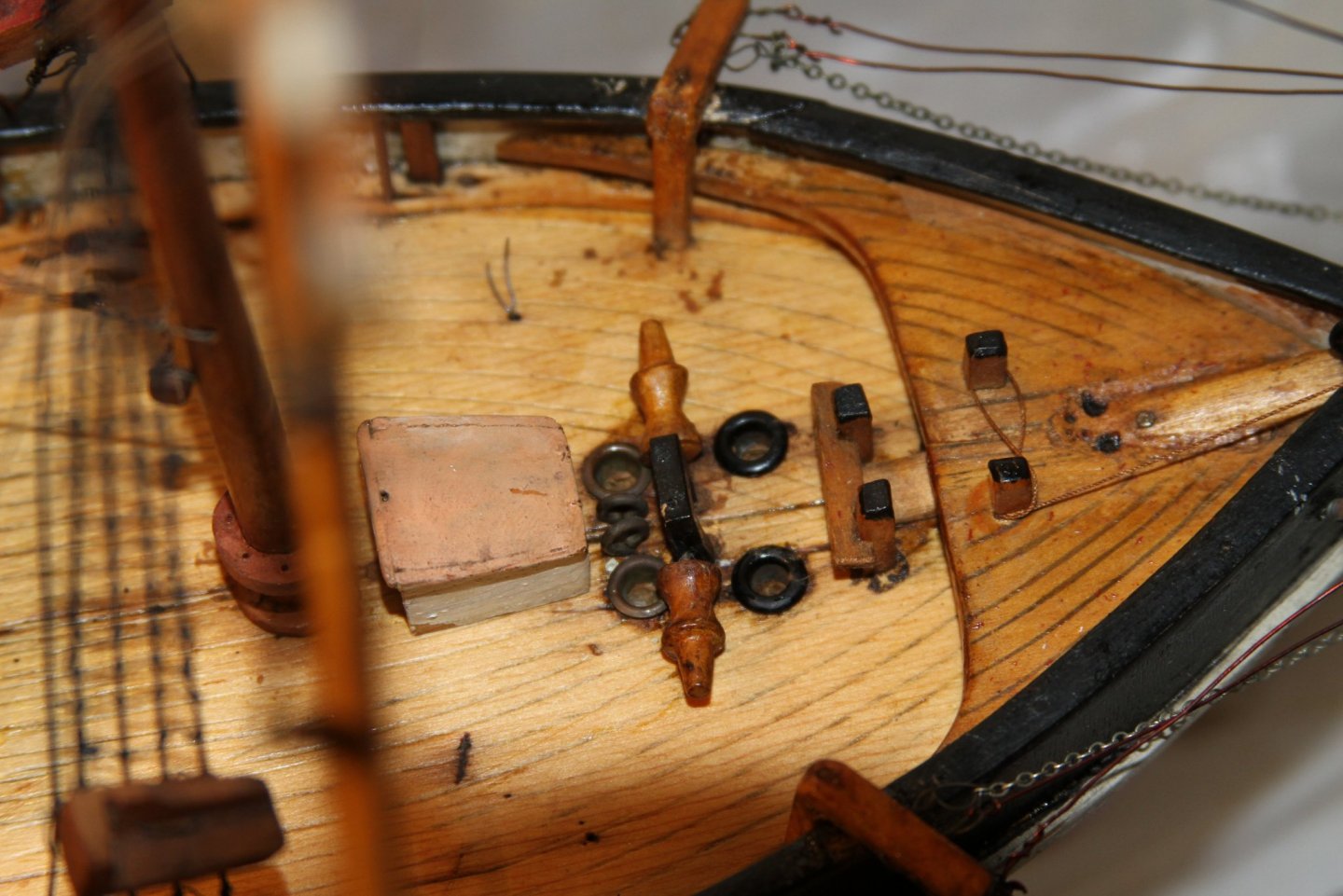
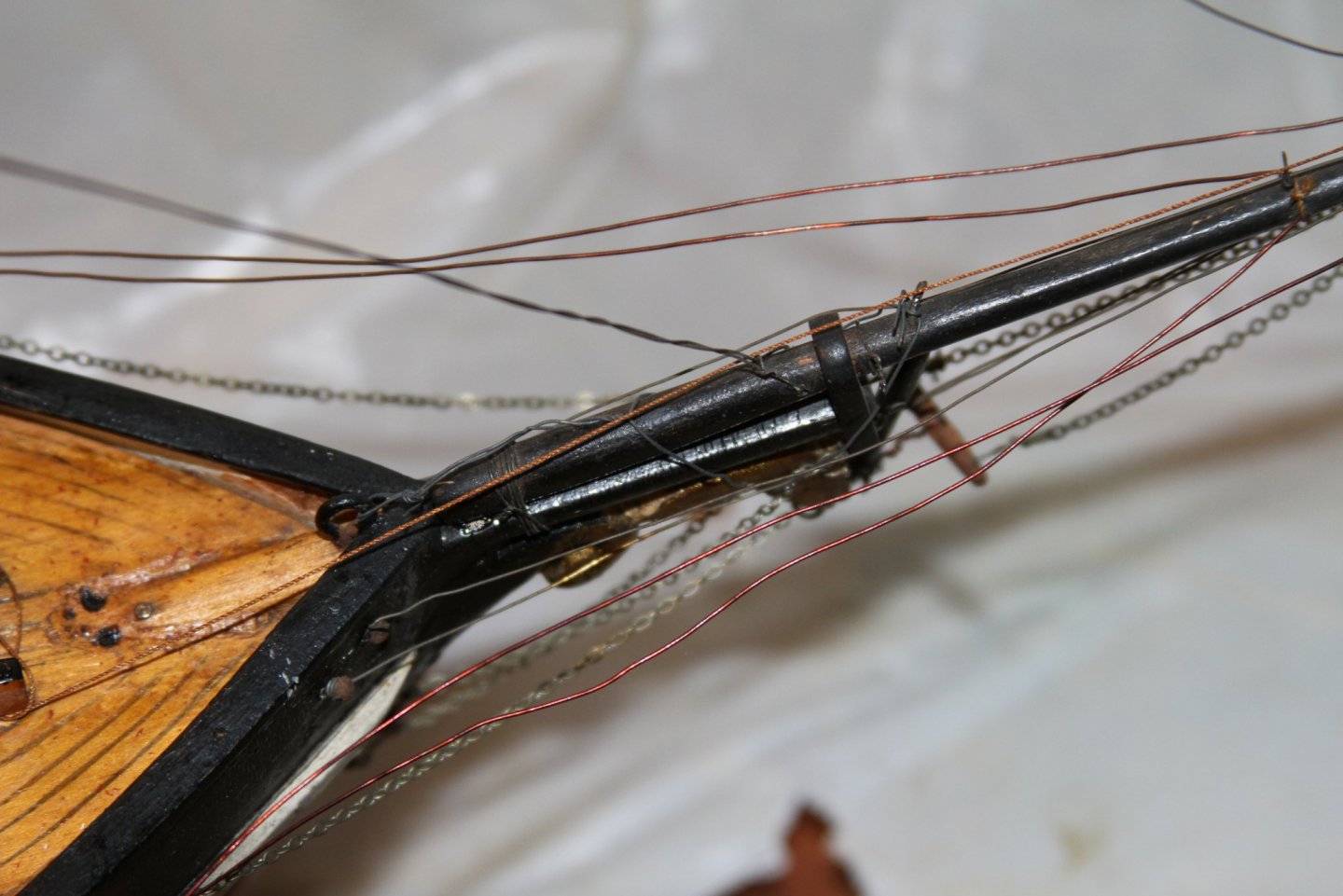
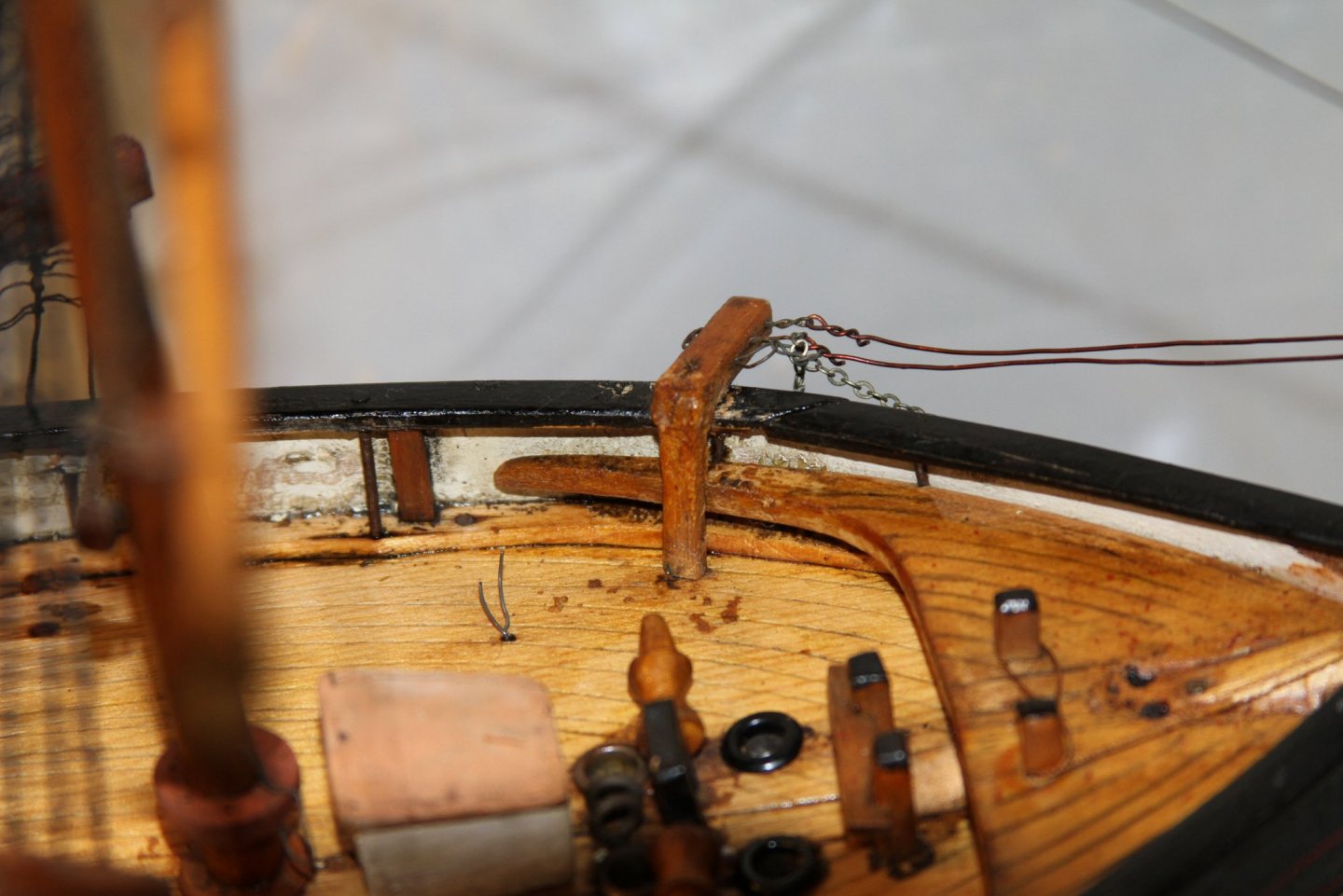
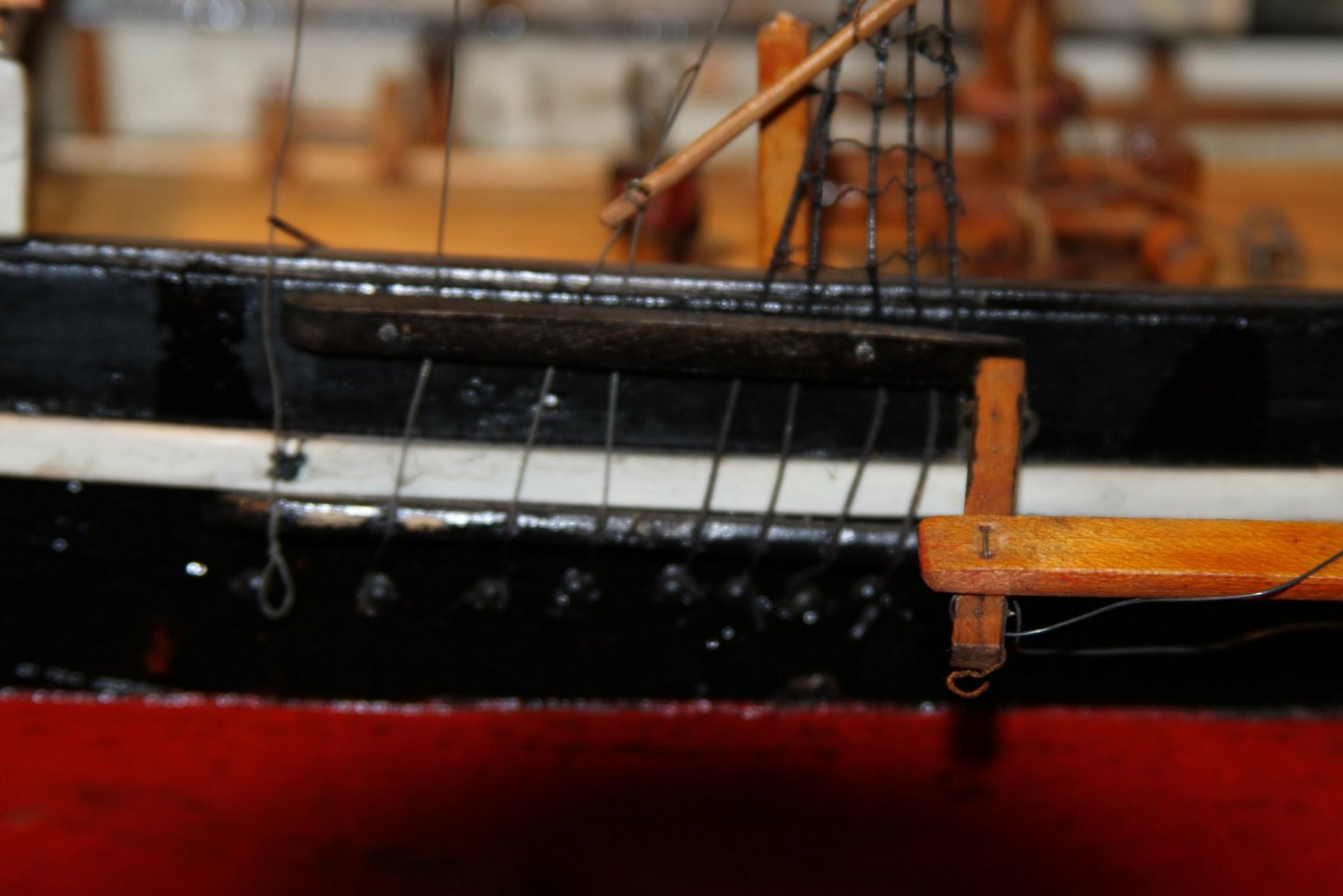
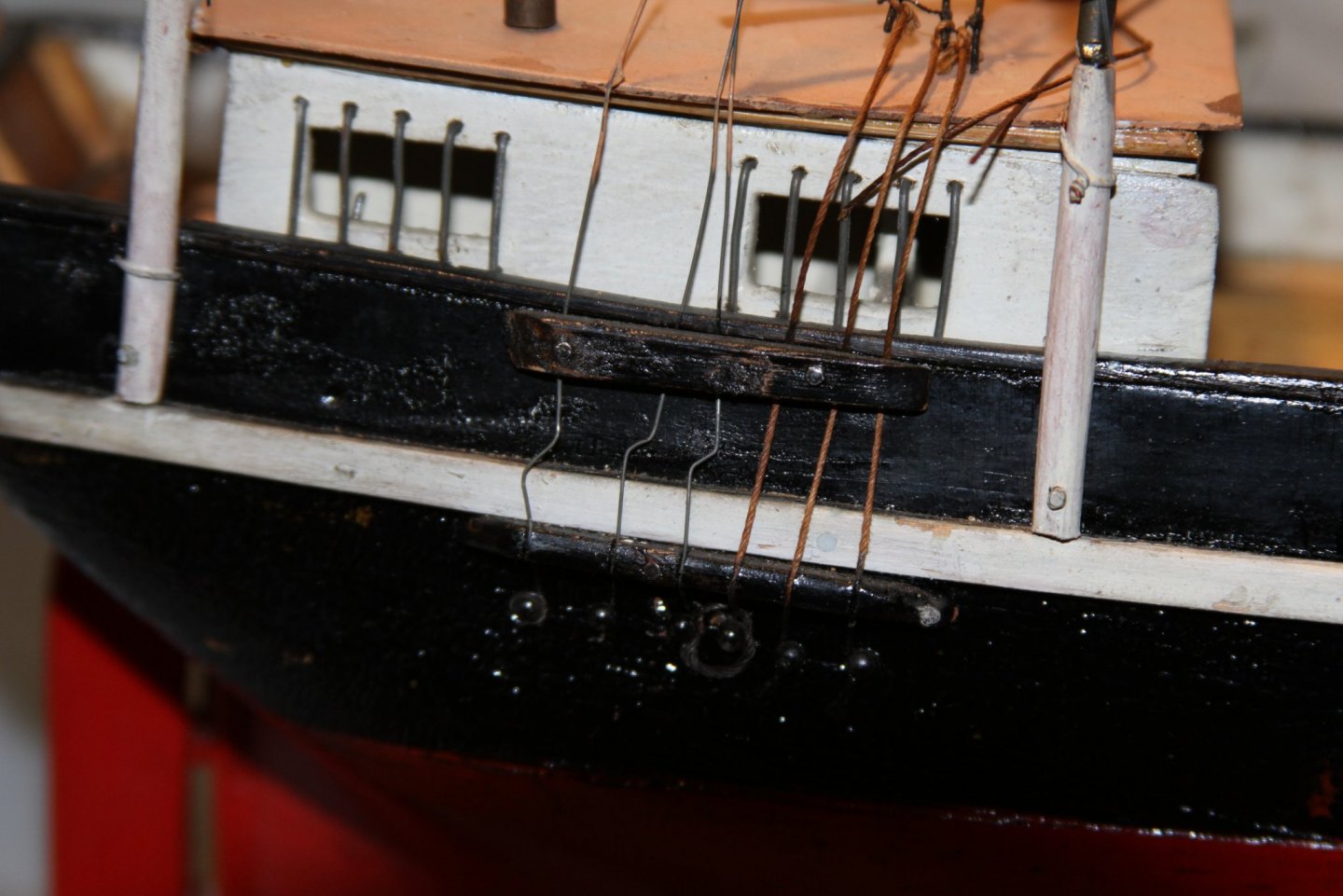
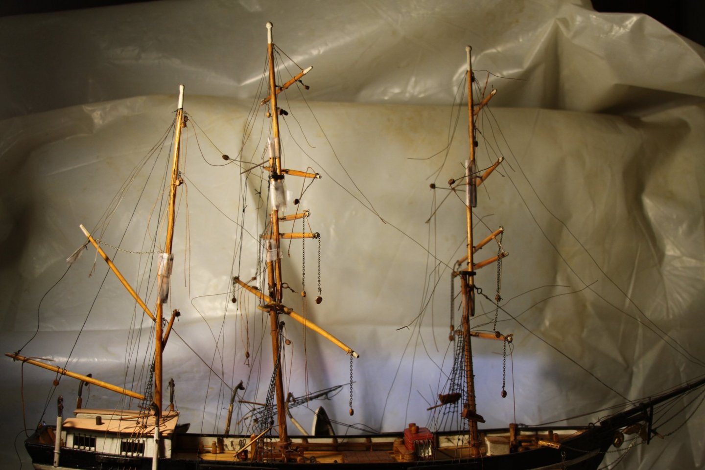
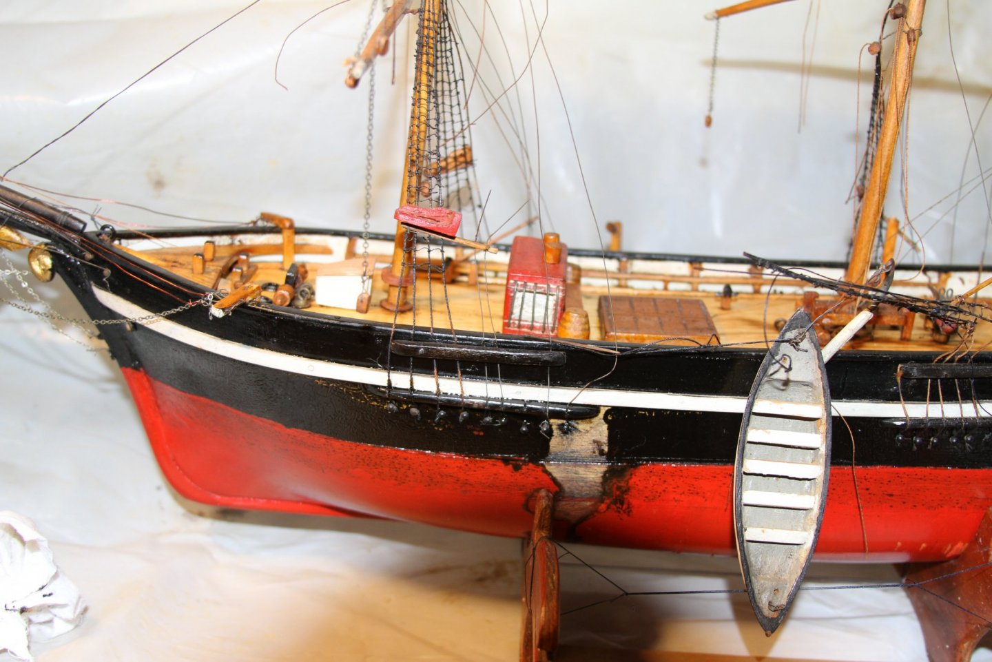
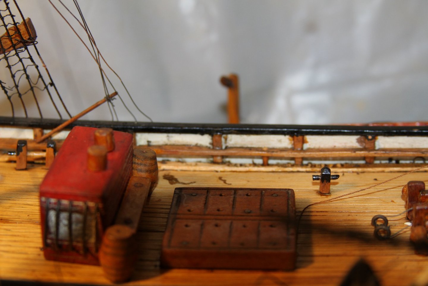
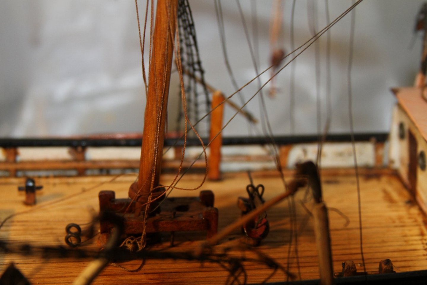
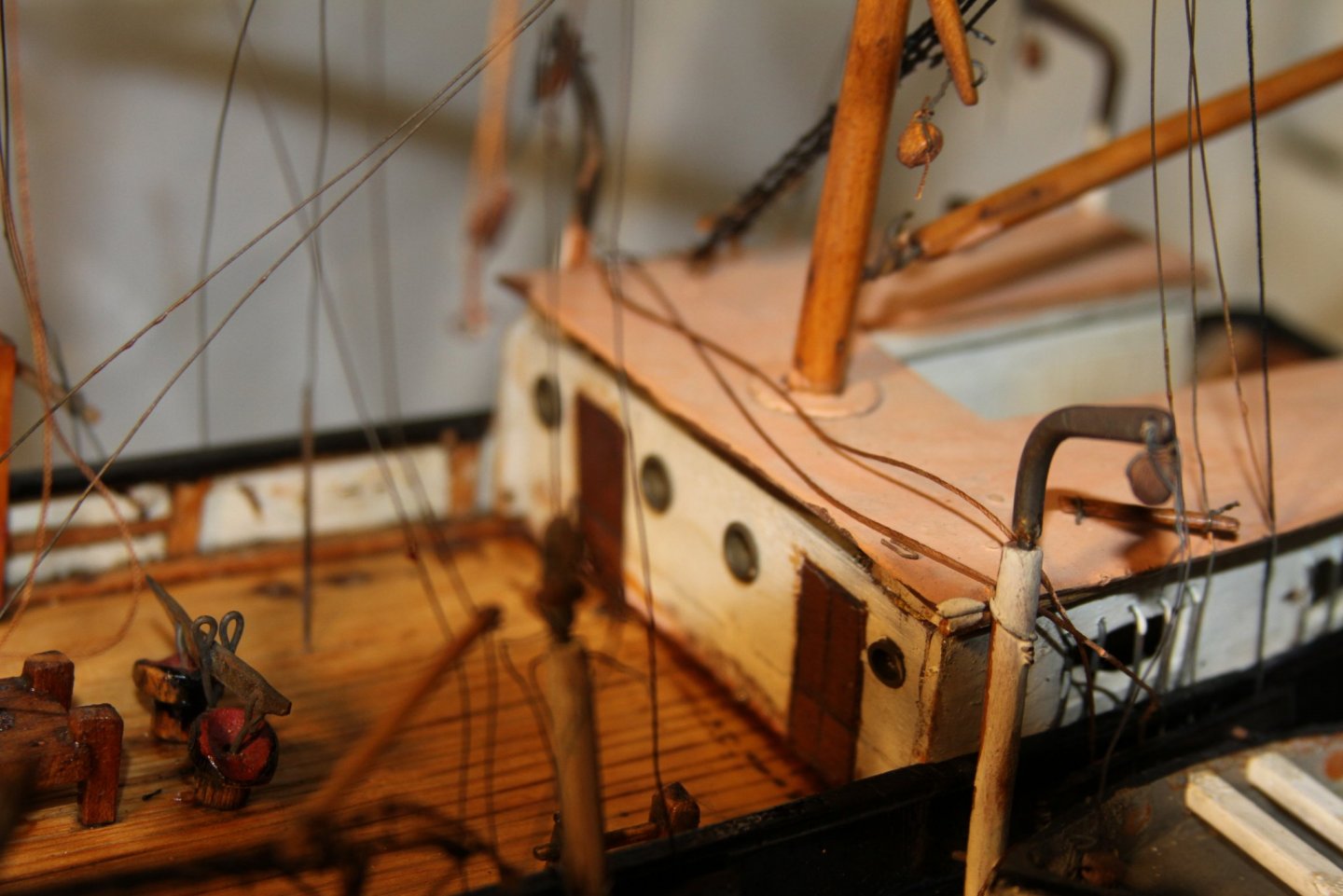
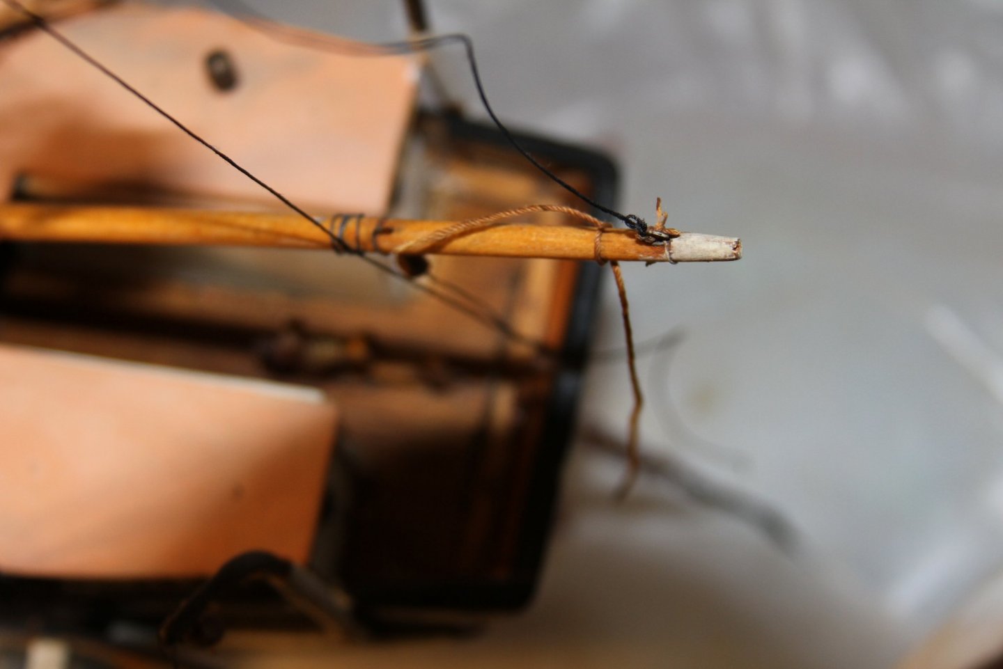
 So here's the start of a nice long and deep project. Unknown Whaling bark. I have to assume that this is not a known ship but the builders idea of what one would look like. The first step I took was photo documenting the ship. Old steel and copper wire was used for the back stays and to tie off the yardarms and pulleys I stripped down all mast and deck fittings, shellac was removed from the deck and the hull was stripped due to orange peeling. The hull was found to be a half *** finishing job with tool marks, too much wood filler or non at all. The last one to paint the hull layed down a very thick coat of oil base paint with no primer. This filled in the gaps and imperfections. My next step is to prep the hull for paint. I still have some design elements to consider. For example the chin plates were slotted and no deadeyes were installed. I noticed that the stays on the mizzen were hitting the deck house and someone had cut groves into the Dh roof to compensate. So the new chain plates will be wider and drilled to allow period chain stays and deadeyes. The gunnels need more frame members added. perceptually in the bow area. Question. Does anyone have a rigging plan for the Wander? The mizzen mast is my focal point for this question. It comes up through the deck house roof and I'm wondering where the halyards are belayed. OK now to dump all pics here.The dump is insurance against computer crash. Note1. I'm trying to stay within the thought of doing no harm to the model. ie allowing its future caretaker to undo what I've done. The new paint will be acrylic. I thought of painting the inner gunnals and mast white but that would kill the charter of the original. The rigging will be completely redone with all the wires removed. Yardarms will get better detailing. Note 2. one of the cool things I noticed is how the deck fittings are attached. The builder used pelted dowels which require no glue. I thought this was brilliant and will use the same when replacing any fittings. Also any leads as to where I can find these? Note 3. How old is this bugger? I'm guessing it was built in the fifties. My only clues are the tops and cross trees. they are made of nitrocellulose. Any thoughts about this are more then welcome. BTW they are almost dust now. So wood will be their replacements. Note 4. Any help on mast rigging plans for pre civil war barks will get you on my Christmas card list. Also input on period fittings. TIA.
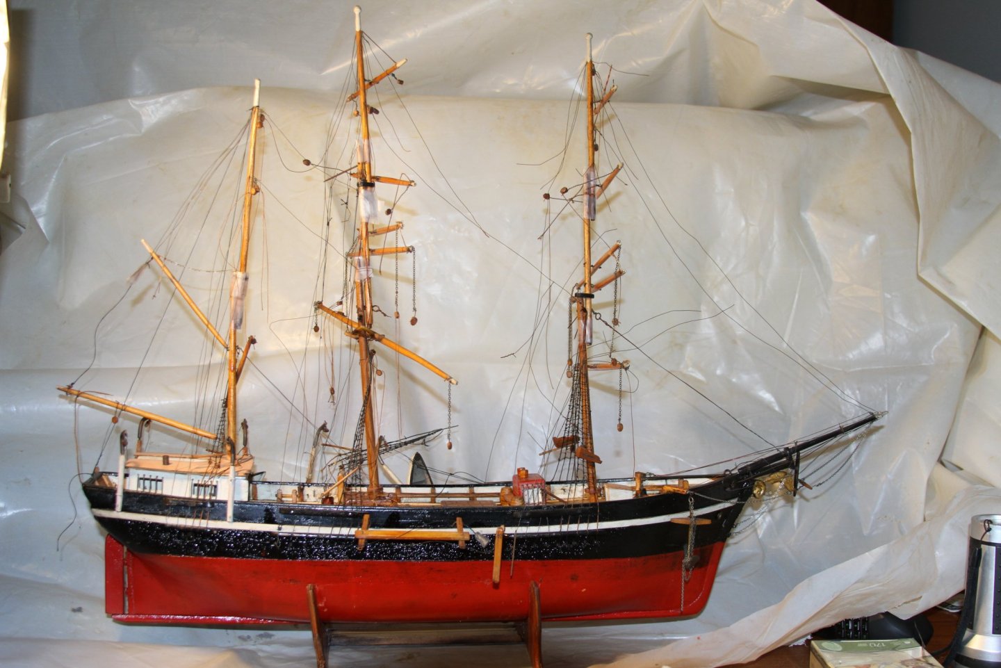


-
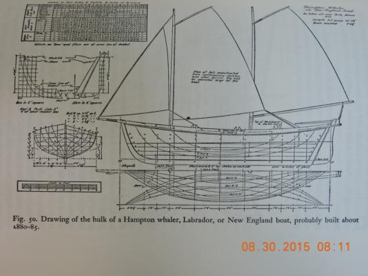
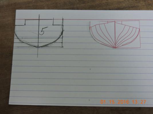
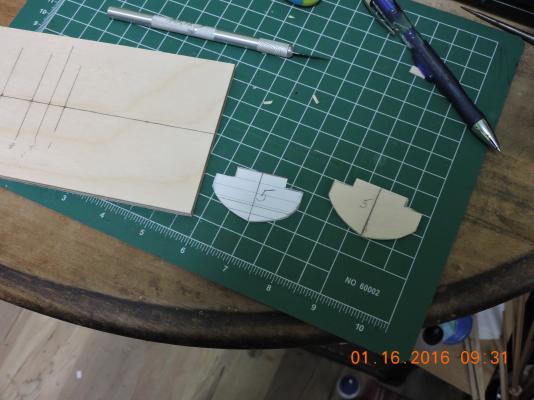
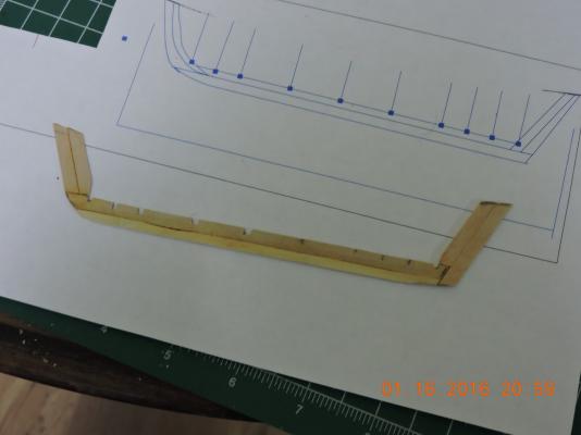
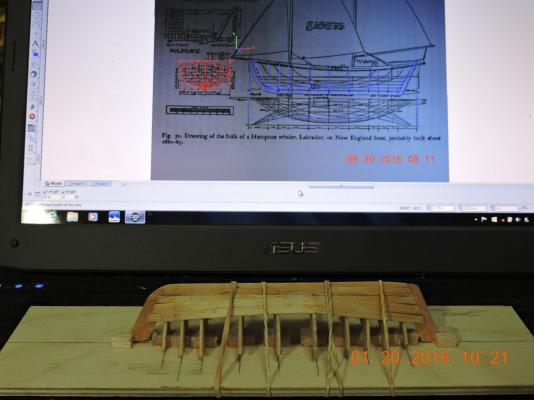
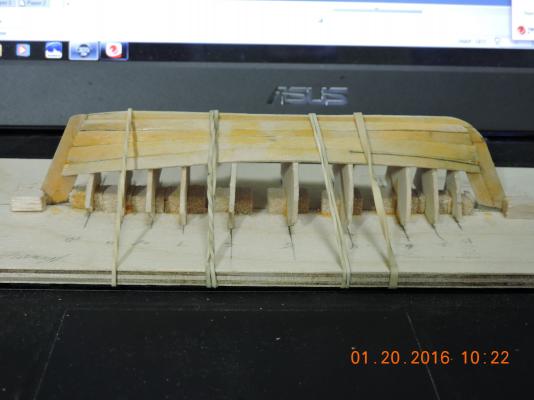
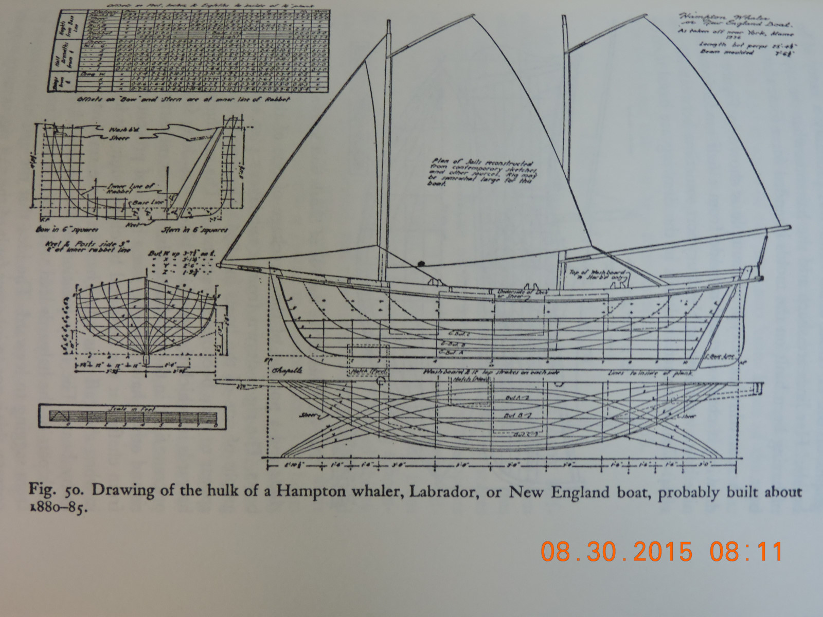
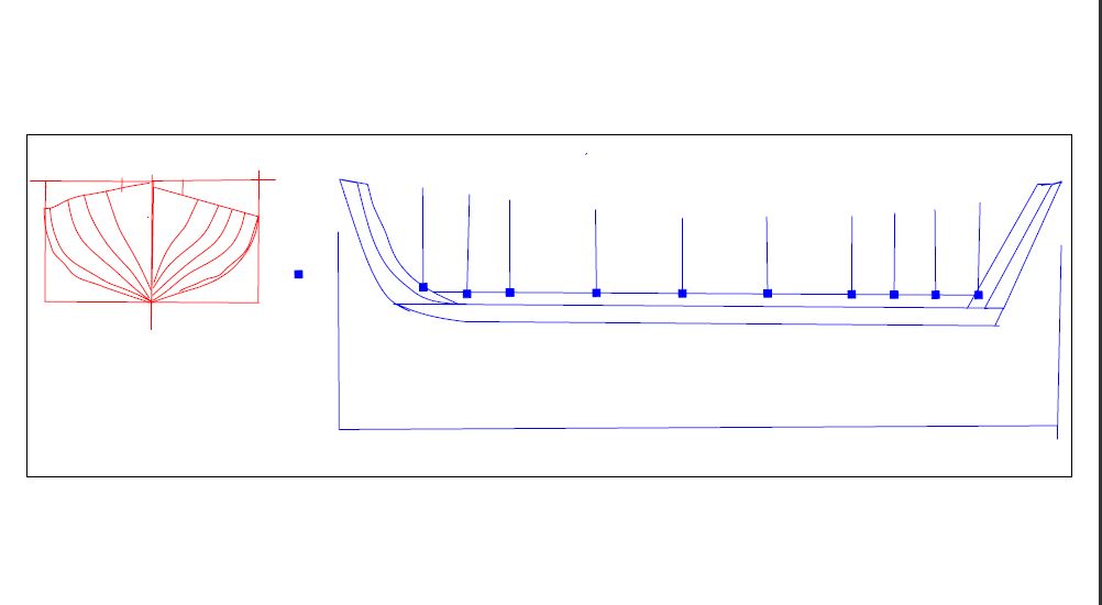
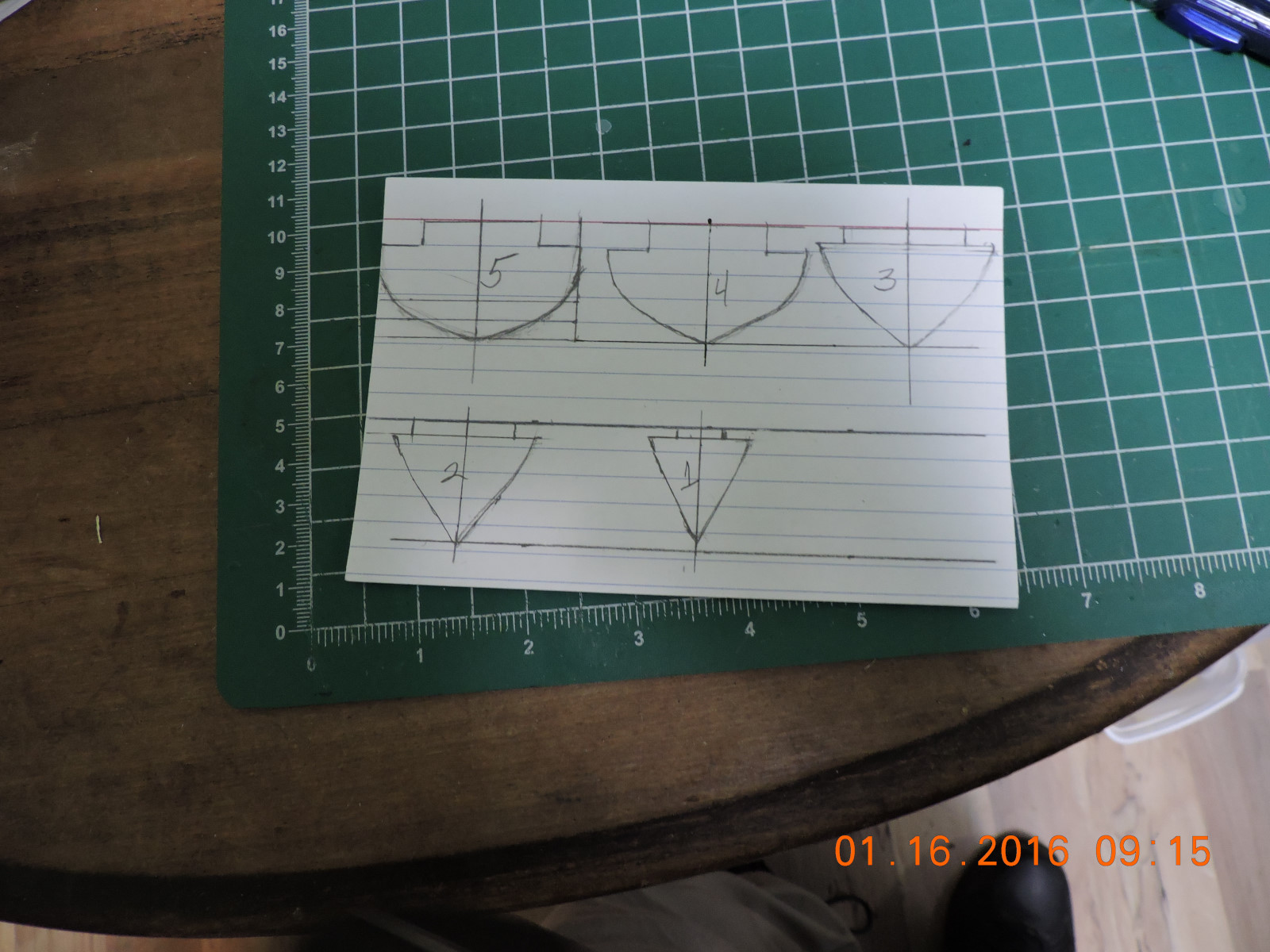
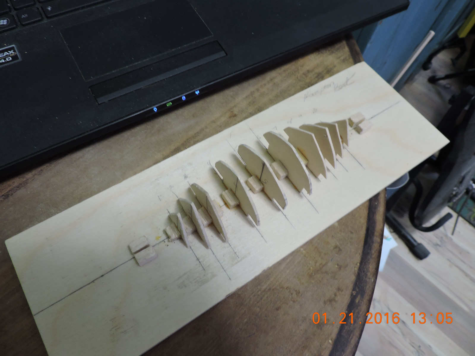
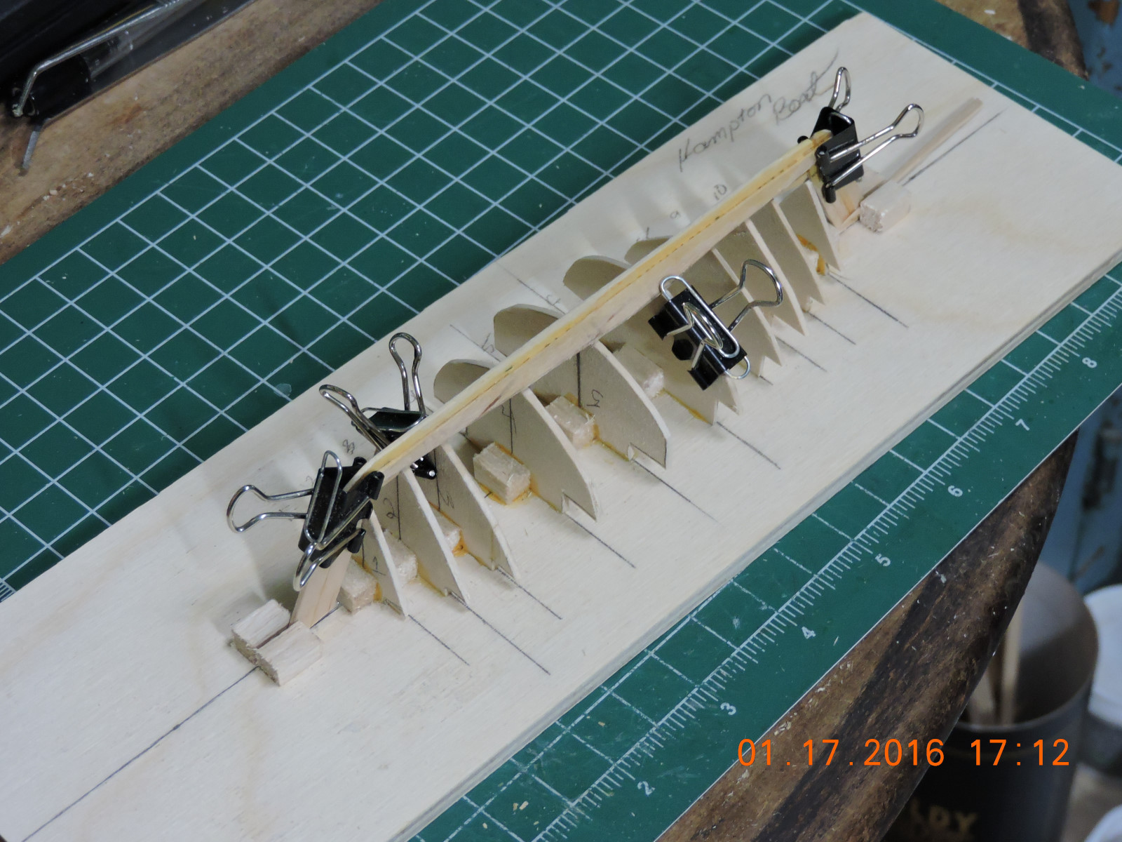
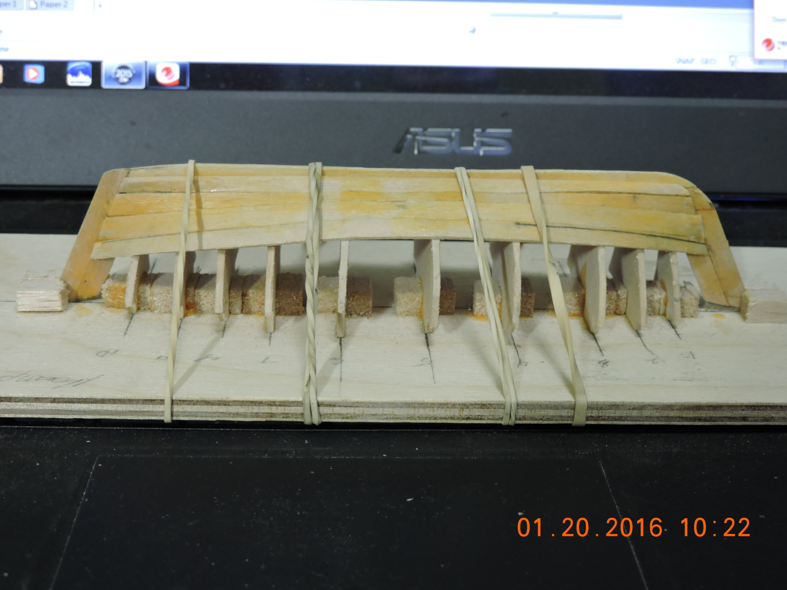
 Hi, The subject of this build is the Hampton Whaler as illustrated on page 143 of Howard I. Chapelle’s book American Small Sailing Craft. For me the purpose of this project is to acquire some Cad drawing skills, enter the world of scratch building and experiment with lifting plans from books. The scale chosen is 1:44 so the boat could be built from coffee stirrers picked up from a famous coffee shop over many visits. The first step of the project was to photograph page 143 and import it into turbo cad. Tracings of the keel and body plan were made and printed. From the body plan molds were made to form the hull. The molds were set up on a piece of plywood. The keel was constructed. The planking will be conducted on the molds and the frames inserted after the planking is completed.